- Продукты, сертифицированные Федеральной комиссией по связи и Министерством промышленности Канады, будут распространяться в США и Канаде. Информацию о них можно получить на соответствующих региональных сайтах ASUS.
- Технические характеристики могут быть изменены без предварительного уведомления. Точную информацию о них вы можете получить у продавца. Доступность продуктов зависит от региона.
- Технические характеристики зависят от конкретной модели продукта – см. страницу спецификаций. Все изображения служат лишь для целей иллюстрации.
- Цвет печатной платы и версии приложенных программ могут быть изменены без предварительного уведомления.
- Упомянутые выше названия продуктов являются торговыми марками соответствующих компаний.
-
Contents
-
Table of Contents
-
Bookmarks
Quick Links
Related Manuals for Asus P6T WS PRO
Summary of Contents for Asus P6T WS PRO
-
Page 1
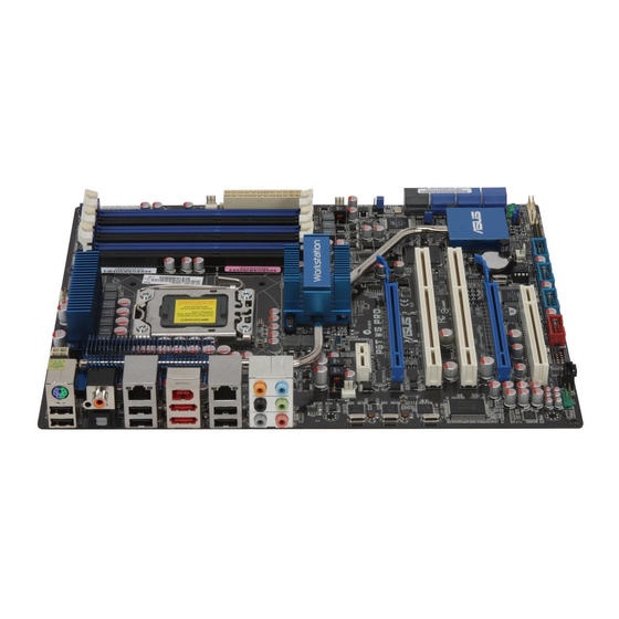
P6T WS Professional… -
Page 2
Product warranty or service will not be extended if: (1) the product is repaired, modified or altered, unless such repair, modification of alteration is authorized in writing by ASUS; or (2) the serial number of the product is defaced or missing. -
Page 3: Table Of Contents
Welcome! ………………1-1 Package contents …………….. 1-1 Special features …………….1-2 1.3.1 Product highlights …………1-2 1.3.2 ASUS Unique features ……….. 1-3 Chapter 2: Hardware information Before you proceed …………..2-1 Motherboard overview …………..2-2 2.2.1 Motherboard layout …………2-2 2.2.2…
-
Page 4: Contents
Chapter 3: BIOS setup Managing and updating your BIOS ……….3-1 3.1.1 ASUS Update utility …………3-1 3.1.2 ASUS EZ Flash 2 utility ……….. 3-4 3.1.3 Creating a bootable floppy disk ……..3-5 3.1.4 AFUDOS utility …………..3-6 3.1.5 ASUS CrashFree BIOS 3 utility ……..3-8 BIOS setup program …………..
-
Page 5
Contents 3.3.5 Storage Configuration ……….. 3-14 3.3.6 AHCI Configuration …………3-15 3.3.7 System Information …………3-16 Ai Tweaker menu ……………. 3-17 3.4.1 Ai Overclock Tuner …………3-17 3.4.2 CPU Ratio Setting …………3-18 3.4.3 Intel(R) SpeedStep(TM) Tech ……..3-18 3.4.4 Intel(R) Turbo Mode Tech ………. -
Page 6
Boot Device Priority …………3-36 3.7.2 Boot Settings Configuration ………. 3-37 3.7.3 Security …………….. 3-38 Tools menu …………….. 3-40 3.8.1 ASUS EZ Flash 2 …………3-40 3.8.2 Express Gate …………… 3-41 3.8.3 ASUS O.C. Profile …………3-42 3.8.4 Ai Net 2 …………….. 3-43 Exit menu ……………… -
Page 7
Contents RAID configurations …………..4-48 4.4.1 RAID definitions …………4-48 4.4.2 Installing Serial ATA hard disks ……..4-49 4.4.3 Intel RAID configurations ……….4-49 ® 4.4.4 Marvell SAS RAID configurations …….. 4-57 ® Creating a RAID driver disk …………4-66 4.5.1 Creating a RAID driver disk without entering the OS .. -
Page 8: Notices
Notices Federal Communications Commission Statement This device complies with Part 15 of the FCC Rules. Operation is subject to the following two conditions: • This device may not cause harmful interference, and • This device must accept any interference received including interference that may cause undesired operation.
-
Page 9: Safety Information
Safety information Electrical safety • To prevent electrical shock hazard, disconnect the power cable from the electrical outlet before relocating the system. • When adding or removing devices to or from the system, ensure that the power cables for the devices are unplugged before the signal cables are connected.
-
Page 10: About This Guide
Refer to the following sources for additional information and for product and software updates. ASUS websites The ASUS website provides updated information on ASUS hardware and software products. Refer to the ASUS contact information. Optional documentation Your product package may include optional documentation, such as warranty flyers, that may have been added by your dealer.
-
Page 11: Conventions Used In This Guide
Conventions used in this guide To make sure that you perform certain tasks properly, take note of the following symbols used throughout this manual. DANGER/WARNING: Information to prevent injury to yourself when trying to complete a task. CAUTION: Information to prevent damage to the components when trying to complete a task.
-
Page 12: P6T Ws Professional Specifications Summary
® * Due to Intel spec definition, DIMMs of DDR3-1333 or above are supported by specific CPU models only. ** Refer to www.asus.com or this user manual for the Memory QVL (Qualified Vendors Lists) Expansion Slots 2 x PCI Express 2.0 x16 slots (at x16 / x16 mode)
-
Page 13
— Coaxial / Optical S/PDIF out ports at back I/O — ASUS Noise Filter ASUS Special features ASUS Exclusive Features: — ASUS EPU-6 Engine — ASUS True 16+2 Phase Power Design — ASUS AI Nap ASUS Workstation Unique Features: — G.P. Diagnosis card — ASUS SASsaby cards support — ASUS WS Diag. -
Page 14
16 Mb AMI BIOS, PnP, DMI 2.0, WfM 2.0, SM BIOS 2.4, Multi-language BIOS Manageability WOL by PME, WOR by PME, Chassis Intrusion, PXE Support DVD Contents Drivers ASUS PC Probe II ASUS Update ASUS AI Suite Image-Editing Suite Anti-virus software (OEM version) Form Factor ATX Form Factor, 12”x 9.6”… -
Page 15: Chapter 1: Product Introduction
This chapter describes the motherboard features and the new technologies it supports. Chapter 1: Product introduction…
-
Page 16
Chapter summary Welcome! ………………1-1 Package contents …………….. 1-1 Special features …………….1-2 ASUS P6T WS Professional… -
Page 17: Welcome
® The motherboard delivers a host of new features and latest technologies, making it another standout in the long line of ASUS quality motherboards! Before you start installing the motherboard, and hardware devices on it, check the items in your package with the list below.
-
Page 18: Special Features
Green ASUS This motherboard and its packaging comply with the European Union’s Restriction on the use of Hazardous Substances (RoHS). This is in line with the ASUS vision of creating environment-friendly and recyclable products/packagings to safeguard consumers’ health while minimizing the impact on the environment.
-
Page 19: Asus Unique Features
ASUS Unique features ASUS TurboV Feel the adrenaline rush of real-time OC—now a reality with the ASUS TurboV. This extreme OC tool lets you set new ambitions on the OC stage with an advanced and easy-to-use interface—allowing you to overclock without exiting or rebooting the OS.
-
Page 20
ASUS Heartbeat Brightly and vividly lighting LEDs shine around the ASUS brand name on the motherboard after successful booting process. With the breathing-like deep blue lighting shining in regular tempo, ASUS Heartbeat makes the motherboard as vivid as life. G.P. Diagnosis card Bundled with P6T WS Professional motherboard (retail version), the G.P. -
Page 21: Asus Quiet Thermal Solution
Fanless Design — Stack Cool 2 ASUS Stack Cool 2 is a fan-less and zero-noise cooling solution that lowers the temperature of critical heat generating components. The motherboard uses a special design on the printed circuit board (PCB) to dissipate heat these critical components generate.
-
Page 22: Tpm Support
4-35 for details. The actual boot time depends on the system configuration. ASUS EZ DIY ASUS EZ DIY feature collection provides you easy ways to install computer components, update the BIOS or back up your favorite settings. ASUS Q-Shield…
-
Page 23: Asus Mylogo2
See page 3-42 for details. ASUS CrashFree BIOS 3 The ASUS CrashFree BIOS 3 allows users to restore corrupted BIOS data from a USB flash disk containing the BIOS file. See page 3-8 for details. ASUS EZ Flash 2 EZ Flash 2 is a user-friendly BIOS update utility.
-
Page 24
Chapter 1: Product Introduction… -
Page 25: Chapter 2: Hardware Information
This chapter lists the hardware setup procedures that you have to perform when installing system components. It includes description of the jumpers and Chapter 2: Hardware connectors on the motherboard. information…
-
Page 26
Central Processing Unit (CPU) ……….. 2-5 System memory …………….. 2-11 Expansion slots …………….2-17 Jumpers ………………2-21 Connectors …………….. 2-24 G.P. Diagnosis card installation ……….2-37 Starting up for the first time …………2-39 2.10 Turning off the computer …………2-40 ASUS P6T WS Professional… -
Page 27: Before You Proceed
ON, in sleep mode, or in soft-off mode. This is a reminder that you should shut down the system and unplug the power cable before removing or plugging in any motherboard component. The illustration below shows the location of the onboard LED. ASUS P6T WS Professional…
-
Page 28: Motherboard Overview
Motherboard overview 2.2.1 Motherboard layout Refer to 2.8 Connectors for more information about rear panel connectors and internal connectors. Chapter 2: Hardware information…
-
Page 29: Layout Contents
USB connectors (10-1 pin USB78, USB910, USB1112) 2-29 IEEE 1394a port connector (10-1 pin IE1394_2) 2-30 Optical drive audio connector (4-pin CD) 2-34 Front panel audio connector (10-1 pin AAFP) 2-32 Digital audio connector (4-1 pin SPDIF_OUT) 2-34 ASUS P6T WS Professional…
-
Page 30: Placement Direction
2.2.3 Placement direction When installing the motherboard, make sure that you place it into the chassis in the correct orientation. The edge with external ports goes to the rear part of the chassis as indicated in the image below. 2.2.4 Screw holes Place nine (9) screws into the holes indicated by circles to secure the motherboard to the chassis.
-
Page 31: Central Processing Unit (Cpu)
ASUS will shoulder the cost of repair only if the damage is shipment/transit-related. • Keep the cap after installing the motherboard. ASUS will process Return Merchandise Authorization (RMA) requests only if the motherboard comes with the cap on the LGA1366 socket.
-
Page 32: Installing The Cpu
2.3.1 Installing the CPU To install a CPU: Locate the CPU socket on the motherboard. Before installing the CPU, make sure that the cam box is facing towards you and the load lever is on your left. Press the load lever with your Retention tab thumb (A), then move it to the left (B) until it is released from the…
-
Page 33
If it gets into your eyes or touches your skin, ensure to wash it off immediately and seek professional medical help. To prevent contaminating the paste, DO NOT spread the paste with your finger directly. ASUS P6T WS Professional… -
Page 34
Close the load plate (A), and then push the load lever (B) until it snaps into the retention tab. Chapter 2: Hardware information… -
Page 35: Installing The Cpu Heatsink And Fan
Push down two fasteners at a time in a diagonal sequence to secure the heatsink and fan assembly in place. Orient the heatsink and fan assembly such that the CPU fan cable is closest to the CPU fan connector. ASUS P6T WS Professional…
-
Page 36: Uninstalling The Cpu Heatsink And Fan
Connect the CPU fan cable to the connector on the motherboard labeled CPU_FAN. DO NOT forget to connect the CPU fan connector! Hardware monitoring errors can occur if you fail to plug this connector. 2.3.3 Uninstalling the CPU heatsink and fan To uninstall the CPU heatsink and fan: Disconnect the CPU fan cable from the connector on the motherboard.
-
Page 37: System Memory
Populated Populated Populated Due to Intel CPU spec definition, the system will not boot if only one DIMM is installed in DIMM slot A2, B2, or C2. Follow the table above for recommended memory configuration. ASUS P6T WS Professional 2-11…
-
Page 38: Memory Configurations
2.4.2 Memory configurations You may install 1GB and 2GB non-ECC, unbuffered DDR3 DIMMs into the DIMM sockets. • You may install varying memory sizes in Channel A, Channel B and Channel C. The system maps the total size of the lower-sized channel for the dual-channel or triple-channel configuration.
-
Page 39: Installing A Dimm
DIMM. DIMM notch Support the DIMM lightly with your fingers when pressing the retaining clips. The DIMM might get damaged when it flips out with extra force. Remove the DIMM from the socket. ASUS P6T WS Professional 2-13…
-
Page 40
P6T WS Professional Motherboard Qualified Vendors Lists (QVL) DDR3-1600MHz capability DIMM socket support (Optional) Chip Vendor Part No. Size Chip No. Brand CORSAIR CM3X1024-1600C7DHXIN(XMP) Heat-Sink Package • • • • Crucial BL12864BA1608.8SFB(XMP) Heat-Sink Package • • • • G.SKILL F3-12800CL7D-2GBHZ Heat-Sink Package 7-7-7-18 •… -
Page 41
• • • Elixir M2F2G64CB8HA4N-CG N2CB1G80AN-CG Elixir • • • • Patriot PDC32G1333LLK Heat-Sink Package Patriot • • • • (Kit of 2) DDR3 1375 Kingston KHX11000D3ULK2/2G Heat-Sink Package • • • (Kit of 2) ASUS P6T WS Professional 2-15… -
Page 42
C1) and the black slot A2 as one set of Triple-channel memory configuration. • D*: Supports six (6) modules inserted into both the orange slots and the black slots as two set of Triple-channel memory configuration. Visit the ASUS website for the latest QVL. 2-16 Chapter 2: Hardware information… -
Page 43: Expansion Slots
IRQ” or that the cards do not need IRQ assignments. Otherwise, conflicts will arise between the two PCI groups, making the system unstable and the card inoperable. Refer to the table on the next page for details. ASUS P6T WS Professional 2-17…
-
Page 44: Interrupt Assignments
2.5.3 Interrupt assignments Standard interrupt assignments Priority Standard function System Timer Keyboard Controller – Redirect to IRQ#9 Communications Port (COM1)* IRQ Holder for PCI Steering* Floppy Disk Controller Reserved System CMOS/Real Time Clock IRQ Holder for PCI Steering* IRQ Holder for PCI Steering* IRQ Holder for PCI Steering* Reserved Numeric Data Processor…
-
Page 45: Pci Slot
2.0 graphic cards complying with the PCI Express specifications. Refer to the figure below for the location of the slots. PCI slot PCIe 2.0 x16_2 slot PCIX_2 slot PCIX_1 slot PCIe 2.0 x16_1 slot PCI Express x1 slot ASUS P6T WS Professional 2-19…
-
Page 46
• In single VGA card mode, use first the PCIe 2.0 x16_1 slot for a PCI Express x16 graphics card to get better performance. • In CrossFireX™ or SLI™ mode, use the PCIe 2.0 x16_1 and PCIe 2.0 x16_2 slots for PCI Express x16 graphics cards to get better performance. •… -
Page 47: Jumpers
• Due to the chipset behavior, AC power off is required to enable C.P.R. function. You must turn off and on the power supply or unplug and plug the power cord before rebooting the system. ASUS P6T WS Professional 2-21…
-
Page 48
CPU / DRAM Bus / QPI DRAM overvoltage setting (3-pin OV_CPU, 3-pin OV_DRAM_BUS, 3-pin OV_QPI_DRAM) These jumpers allow you to enable or disable the advanced CPU, DRAM Bus, and QPI DRAM overvoltage settings in BIOS. Read the following information before you change the jumper settings. OV_CPU OV_DRAM_BUS OV_QPI_DRAM… -
Page 49
This jumper allows you to set the PCI-X slot’s maximum frequency capability. The jumper cap on pins 1-2: Auto detection The jumper cap on pins 3-4: 133 MHz capability for the PCI-X slot. The jumper cap on pins 5-6: 100 MHz capability for the PCI-X slot. ASUS P6T WS Professional 2-23… -
Page 50: Connectors
Connectors 2.7.1 Rear panel connectors PS/2 keyboard / mouse combo port. This port is for a PS/2 keyboard or a PS/2 mouse. Coaxial S/PDIF Out port. This port connects an external audio output device via a coaxial S/PDIF cable. LAN 2 (RJ-45) port. This Marvell LAN port allows Gigabit connection to a ®…
-
Page 51
15. Optical S/PDIF Out port. This port connects an external audio output device via an optical S/PDIF cable. 16. USB 2.0 ports 5 and 6. These 4-pin Universal Serial Bus (USB) ports are available for connecting USB 2.0 devices. ASUS P6T WS Professional 2-25… -
Page 52: Internal Connectors
2.7.2 Internal connectors TPM connector (20-1 pin TPM) [Optional] This connector supports a Trusted Platform Module (TPM) system, which can securely store keys, digital certificates, passwords, and data. A TPM system also helps enhance network security, protects digital identities, and ensures platform integrity.
-
Page 53
Windows XP or later version. ® • When using hot-plug and NCQ, set the Configure SATA as in the BIOS to [AHCI]. See section 3.3.5 Storage Configuration for details. ASUS P6T WS Professional 2-27… -
Page 54
Marvell 88SE6320 SAS RAID connectors [black] (7-pin SAS1-2) ® These connectors are for SAS (Serial Attached SCSI) signal cables that support SAS hard disk drives. To configure RAID 0 or RAID 1, install two SAS hard disk drives to these two connectors. •… -
Page 55
If your chassis suppots front panel USB ports, you can attach a front panel USB cable to these connectors. Connect the USB cable to ASUS Q-Connector (USB, blue) first, and then install the Q-Connector (USB) to the USB connector onboard. -
Page 56
IEEE 1394a port connector (10-1 pin IE1394_2) This connector is for an IEEE 1394a port. Connect the IEEE 1394a module cable to this connector, then install the module to a slot opening at the back of the system chassis. Never connect a USB cable to the IEEE 1394a connector. Doing so will damage the motherboard! You can attach a FireWire/1394 cable to this connector if your chassis suppots the front panel IEEE1394 port. -
Page 57
These are not jumpers! Do not place jumper caps on the fan connectors! • Only the CPU-FAN and CHA-FAN 1–3 connectors support the ASUS Advanced Q-Fan feature. • If you install two or more VGA cards, we recommend that you plug the rear chassis fan cable to the motherboard connector labled CHA_FAN2 or CHA_FAN3 for better thermal environment. -
Page 58
Chassis intrusion connector (4-1 pin CHASSIS) This connector is for a chassis-mounted intrusion detection sensor or switch. Connect one end of the chassis intrusion sensor or switch cable to this connector. The chassis intrusion sensor or switch sends a high-level signal to this connector when a chassis component is removed or replaced. -
Page 59
If you want to use two or more high-end PCI Express x16 cards, use a PSU with 1000 W power or above to ensure the system stability. PSU suggested list PSU suggested list SilverStone ST1000 Seasonic SS-600HT Thermaltake W0083RE Thermaltake PUREPower-600AP Silverstone SST-ST75ZF EnerMAX EG701AX-VE (E)(24P) ASUS P6T WS Professional 2-33… -
Page 60
11. Digital audio connector (4-1 pin SPDIF) This connector is for an additional Sony/Philips Digital Interface (S/PDIF) port(s). If you are using ASUS HDMI-equipped graphics card, connect the HDMI card to this connector with a S/PDIF out cable. The S/PDIF out cable are purchased separately. -
Page 61: System Panel Connector
BIOS settings. Pressing the power switch for more than four seconds while the system is ON turns the system OFF. • Reset button (2-pin RESET) This 2-pin connector is for the chassis-mounted reset button for system reboot without turning off the system power. ASUS P6T WS Professional 2-35…
-
Page 62: Asus Q-Connector
ASUS Q-Connector (system panel) You can use the ASUS Q-Connector to connect/disconnect chassis front panel cables in a few steps. Refer to the instructions below to install the ASUS Q-Connector. Connect the front panel cables to the ASUS Q-Connector. Refer to the labels on the Q-Connector…
-
Page 63: G.p. Diagnosis Card Installation
Locate the TPM connector (20-1 pin TPM) on the motherboard. With the LEDs of the diagnosis card facing to the SATA ports, align the card connector with the TPM connector and press firmly until the card sits on the connector completely. ASUS P6T WS Professional 2-37…
-
Page 64: G.p. Diagnosis Card Check Codes
2.8.3 G.P. Diagnosis card check codes Initiate chip Detect IDE Enable IO device for bootlock Initiate option ROM Check and wake up system Show post error Enter BIOS setup Prepare system for memory detection and sizing BIOS boot menu Memory test OS in PIC mode Copy BIOS from ROM to RAM OS in APIC mode…
-
Page 65: Starting Up For The First Time
No VGA detected short beeps One continuous beep followed by four Hardware component failure short beeps At power on, hold down the <Delete> key to enter the BIOS Setup. Follow the instructions in Chapter 3. ASUS P6T WS Professional 2-39…
-
Page 66: 2.10 Turning Off The Computer
2.10 Turning off the computer 2.10.1 Using the OS shut down function If you are using Windows Vista™: ® Click the Start button then select Shut Down. The power supply should turn off after Windows shuts down. ® If you are using Windows ®…
-
Page 67: Chapter 3: Bios Setup
This chapter tells how to change the system settings through the BIOS Setup menus. Detailed descriptions of the BIOS parameters are also provided. BIOS setup…
-
Page 68
Managing and updating your BIOS ……….3-1 BIOS setup program …………..3-9 Main menu ……………… 3-12 Ai Tweaker ……………… 3-17 Advanced menu …………….. 3-25 Power menu …………….3-32 Boot menu ……………… 3-36 Tools menu …………….. 3-40 Exit menu ………………3-44 ASUS P6T WS Professional… -
Page 69: Managing And Updating Your Bios
ASUS Update (Updates the BIOS in Windows environment.) ® ASUS EZ Flash 2 (Updates the BIOS using a floppy disk or USB flash disk.) ASUS AFUDOS (Updates the BIOS using a bootable floppy disk) ASUS CrashFree BIOS 3 (Updates the BIOS using a bootable floppy disk, USB flash disk or the motherboard support DVD when the BIOS file fails or gets corrupted.)
-
Page 70
To update the BIOS through the Internet: Launch the ASUS Update utility from the Windows desktop by clicking Start ® > Programs > ASUS > ASUSUpdate > ASUSUpdate. The ASUS Update main window appears. Select Update BIOS from the Select the ASUS FTP site nearest… -
Page 71
To update the BIOS through a BIOS file: Launch the ASUS Update utility from the Windows desktop by clicking Start ® > Programs > ASUS > ASUSUpdate > ASUSUpdate. The ASUS Update main window appears. Select Update BIOS from a file option from the drop-down menu, then click Next. -
Page 72: Asus Ez Flash 2 Utility
3.1.2 ASUS EZ Flash 2 utility The ASUS EZ Flash 2 feature allows you to update the BIOS without having to go through the long process of booting from a floppy disk and using a DOS-based utility. The EZ Flash 2 utility is built-in the BIOS chip so it is accessible by pressing <Alt>…
-
Page 73: Creating A Bootable Floppy Disk
Right-click Floppy Disk Drive then click Format to display the Format 3 1/2 Floppy dialog box . d. Select the Create an MS-DOS startup disk check box. e. Click Start. Copy the original or the latest motherboard BIOS file to the bootable floppy disk. ASUS P6T WS Professional…
-
Page 74: Afudos Utility
Updating the BIOS file To update the BIOS file using the AFUDOS utility: Visit the ASUS website (www.asus.com) and download the latest BIOS file for the motherboard. Save the BIOS file to a bootable floppy disk. Chapter 3: BIOS setup…
-
Page 75
Reboot the system from the hard disk drive. A:\>afudos /iP6TWS.ROM AMI Firmware Update Utility — Version 1.19(ASUS V2.07(03.11.24BB)) Copyright (C) 2002 American Megatrends, Inc. All rights reserved. WARNING!! Do not turn off power during flash BIOS Reading file ..done Reading flash ..done Advance Check ..Erasing flash ..done Writing flash ..done Verifying flash ..done Please restart your computer A:\> ASUS P6T WS Professional… -
Page 76: Asus Crashfree Bios 3 Utility
3.1.5 ASUS CrashFree BIOS 3 utility The ASUS CrashFree BIOS 3 is an auto recovery tool that allows you to restore the BIOS file when it fails or gets corrupted during the updating process. You can update a corrupted BIOS file using the motherboard support DVD, the floppy disk, or the USB flash disk that contains the updated BIOS file.
-
Page 77: Bios Setup Program
The BIOS setup screens shown in this section are for reference purposes only, and may not exactly match what you see on your screen. • Visit the ASUS website (www.asus.com) to download the latest BIOS file for this motherboard. ASUS P6T WS Professional…
-
Page 78: Bios Menu Screen
3.2.1 BIOS menu screen Menu items Menu bar Configuration fields General help BIOS SETUP UTILITY Main Ai Tweaker Advanced Power Boot Tools Exit Use [ENTER], [TAB] System Time [13:51:25] or [SHIFT-TAB] to System Date [Thu 10/02/2008] select a field. Language [English] Use [+] or [-] SATA1 [HDT722516DLA380] to configure the SATA2 [Not Detected] System Time. SATA3 [ATAPI DVD DH1] SATA4 [Not Detected] SATA5 [Not Detected] SATA6 [Not Detected] Select Screen…
-
Page 79: Menu Items
Up/Down arrow keys or <Page Up> /<Page Scroll bar Down> keys to display the other items on the screen. 3.2.9 General help At the top right corner of the menu screen is a brief description of the selected item. ASUS P6T WS Professional 3-11…
-
Page 80: Main Menu
Main menu When you enter the BIOS Setup program, the Main menu screen appears, giving you an overview of the basic system information. Refer to section 3.2.1 BIOS menu screen for information on the menu screen items and how to navigate through them. BIOS SETUP UTILITY Main Ai Tweaker Advanced Power Boot Tools Exit Use [ENTER], [TAB]…
-
Page 81: Sata 1-6
When set to [Disabled], the data transfer from and to the device occurs one sector at a time. Configuration options: [Disabled] [Auto] PIO Mode [Auto] Allows you to select the data transfer mode. Configuration options: [Auto] [0] [1] [2] [3] [4] ASUS P6T WS Professional 3-13…
-
Page 82: Storage Configuration
DMA Mode [Auto] Selects the DMA mode. Configuration options: [Auto] [SWDMA0] [SWDMA1] [SWDMA2] [MWDMA0] [MWDMA1] [MWDMA2] [UDMA0] [UDMA1] [UDMA2] [UDMA3] [UDMA4] [UDMA5] SMART Monitoring [Auto] Sets the Self-Monitoring, Analysis, and Reporting Technology. Configuration options: [Auto] [Disabled] [Enabled] 32Bit Data Transfer [Enabled] Enables or disables 32-bit data transfer.
-
Page 83: Ahci Configuration
SATA Port1 [Auto] Allows you to select the type of device connected to the system. Configuration options: [Auto] [Not Installed] SMART Monitoring [Enabled] Allows you to set the Self-Monitoring, Analysis and Reporting Technology. Configration options: [Disabled] [Enabled] ASUS P6T WS Professional 3-15…
-
Page 84: System Information
3.3.7 System Information This menu gives you an overview of the general system specifications. The BIOS automatically detects the items in this menu. BIOS SETUP UTILITY Main Bios Information Version : 0201 Build Date : 10/01/08 Processor Type : Genuine Intel(R) CPU @ 2.67GHz Speed : 2666MHz System Memory Usable Size : 1016MB Select Screen Select Item F1 General Help F10 Save and Exit ESC Exit v02.61 (C)Copyright 1985-2008, American Megatrends, Inc.
-
Page 85: Ai Tweaker Menu
Overclocks DRAM frequency by adjusting BCLK frequency. X.M.P. If you install memory module(s) supporting the eXtreme Memory Profile (X.M.P.) Technology, choose this item to set the profile(s) supported by your memory module(s) for optimizing the system performance. ASUS P6T WS Professional 3-17…
-
Page 86: Cpu Ratio Setting
The configuration options for the following sub-item vary depending on the DIMMs you install on the motherboard. DRAM O.C. Profile [DDR3-1339MHz] This item appears only when you set the Ai Overclock Tuner item to [D.O.C.P.] and allows you to select a DRAM O.C. profile, which applies different settings to DRAM frequency, DRAM timing and DRAM voltage.
-
Page 87: Dram Frequency
DRAM REF Cycle Time [Auto] Configuration options: [Auto] [30 DRAM Clock] [36 DRAM Clock] [48 DRAM Clock] [60 DRAM Clock] [72 DRAM Clock] [82 DRAM Clock] [88 DRAM Clock] [90 DRAM Clock] [100 DRAM Clock] [110 DRAM Clock] ASUS P6T WS Professional 3-19…
-
Page 88
DRAM WRITE Recovery Time [Auto] Configuration options: [Auto] [1 DRAM Clock] – [15 DRAM Clock] DRAM READ to PRE Time [Auto] Configuration options: [Auto] [1 DRAM Clock] – [15 DRAM Clock] DRAM FOUR ACT WIN Time [Auto] Configuration options: [Auto] [1 DRAM Clock] – [31 DRAM Clock] DRAM WRITE to READ Delay [Auto] Configuration options: [Auto] [1 DRAM Clock] –… -
Page 89: Cpu Voltage
The value [1.90000V] of the QPI/DRAM Core Voltage item is supported only if the OV_QPI_DRAM jumper is enabled. Otherwise the maximum voltage supported is [1.70000V]. See 2. CPU / DRAM Bus / QPI DRAM overvoltage setting on page 2-22 for details. ASUS P6T WS Professional 3-21…
-
Page 90: Ioh Voltage
3.4.10 IOH Voltage [Auto] Allows you to set the I/O Hub (IOH) voltage. The values range from 1.10V to 1.70V with a 0.02V interval. 3.4.11 IOH PCIE Voltage [Auto] Allows you to set the IOH PCIE voltage. The values range from 1.50V to 2.76V with a 0.02V interval.
-
Page 91: Dram Data Ref Voltage On Cha/B/C
3.4.19 CPU Clock Skew [Auto] Adjusting this item may help enhancing BCLK overclocking ability. You may need to adjust the IOH Clock Skew item at the same time. Configuration options: [Auto] [Normal] [Delay 100ps]–[Delay 1500ps] ASUS P6T WS Professional 3-23…
-
Page 92: Cpu Spread Spectrum
3.4.20 CPU Spread Spectrum [Auto] Set to [Disabled] to enhance BCLK overclocking ability or [Auto] for EMI control. Configuration options: [Auto] [Disabled] [Enabled] 3.4.21 IOH Clock Skew [Auto] Adjusting this item may help enhancing BCLK overclocking ability. You may need to adjust the CPU Clock Skew item at the same time.
-
Page 93: Advanced Menu
Hardware Prefetcher [Enabled] F10 Save and Exit Adjacent Cache Line Prefetch [Enabled] ESC Exit Intel(R) Virtualization Tech [Enabled] CPU TM function [Enabled] v02.61 (C)Copyright 1985-2008, American Megatrends, Inc. Scroll down to display the following items: Execute-Disable Bit [Enabled] Intel(R) HT Technology [Enabled] Active Processor Cores [All] A20M [Disabled] Intel(R) SpeedStep(TM) Tech [Enabled] Intel(R) TurboMode tech [Enabled] Intel(R) C-STATE Tech [Disabled] v02.61 (C)Copyright 1985-2008, American Megatrends, Inc. ASUS P6T WS Professional 3-25…
-
Page 94
CPU Ratio Setting [Auto] Allows you to adjust the ratio between CPU Core Clock and BCLK Frequency. Use the <+> and <-> keys to adjust the value. Configuration options: [Auto] [12.0] [13.0] [14.0] [15.0] [16.0] [17.0] [18.0] [19.0] [20.0] C1E Support [Enabled] Allows you to enable or disable Enhanced Halt State support. -
Page 95
This item appears only when you set the Intel(R) C-STATE Tech item to [Enabled]. We recommend that you set this item to [Auto] for BIOS to automatically detect the C-State mode supported by your CPU. Configuration options: [Auto] [C1] [C3] [C6] [C7] ASUS P6T WS Professional 3-27… -
Page 96: Chipset
3.5.2 Chipset The Chipset menu allows you to change the advanced chipset settings. Select an item then press <Enter> to display the sub-menu. BIOS SETUP UTILITY Advanced Advanced Chipset Settings Configure North Bridge features. WARMING: Setting wrong values in below sections may cause system to malfunction. North Bridge Configuration Intel VT-d Configuration North Bridge Chipset Configuration BIOS SETUP UTILITY Advanced North Bridge Chipset Configuration…
-
Page 97: Onboard Device Configuration
If you enable the Marvell Storage Boot ROM item or set ICH10R SATA mode to [RAID], the SAS Boot ROM item will be disabled and hidden. Realtek LAN1/2 [Enabled] Allows you to enable or disable the onboard Realtek LAN port1/2. Configuration options: [Enabled] [Disabled] ASUS P6T WS Professional 3-29…
-
Page 98: Usb Configuration
LAN Boot ROM [Disabled] This item appears only when you enable the previous item. Configuration options: [Disabled] [Enabled] Onboard 1394 Controller [Enabled] Allows you to enabled or disable the onboard IEEE 1394a controller. Configuration options: [Enabled] [Disabled] 3.5.4 USB Configuration The items in this menu allows you to change the USB-related features.
-
Page 99: Pcipnp
When set to [NO], BIOS configures all the devices in the system. When set to [YES] and if you install a Plug and Play operating system, the operating system configures the Plug and Play devices not required for boot. Configuration options: [No] [Yes] ASUS P6T WS Professional 3-31…
-
Page 100: Power Menu
Power menu The Power menu items allow you to change the settings for the Advanced Power Management (APM). Select an item then press <Enter> to display the configuration options. BIOS SETUP UTILITY Main Ai Tweaker Advanced Power Boot Tools Exit Select the ACPI state Suspend Mode [Auto] used for System Repost Video on S3 Resume [No] Suspend. ACPI 2.0 Support [Disabled] ACPI APIC Support [Enabled] APM Configuration…
-
Page 101: Apm Configuration
Allows you to disable the Power On by PS/2 keyboard function or set specific keys on the PS/2 keyboard to turn on the system. This feature requires an ATX power supply that provides at least 1A on the +5VSB lead. Configuration options: [Disabled] [Space Bar] [Ctrl-Esc] [Power Key] ASUS P6T WS Professional 3-33…
-
Page 102: Hardware Monitor
The following item appears only when you enable the CPU Q-Fan Control item. CPU Fan Profile [Standard] Allows you to set the appropriate performance level of the ASUS Q-Fan. When set to [Standard], the CPU fan automatically adjusts depending on the CPU temperature.
-
Page 103
Chassis Fan Profile [Standard] Allows you to set the appropriate performance level of the ASUS Q-Fan. When set to [Standard], the chassis fan automatically adjusts depending on the chassis temperature. Set this item to [Silent] to minimize fan speed for quiet chassis fan operation, or [Turbo] to achieve maximum chassis fan speed. -
Page 104: Boot Menu
Boot menu The Boot menu items allow you to change the system boot options. Select an item then press <Enter> to display the sub-menu. BIOS SETUP UTILITY Main Ai Tweaker Advanced Power Boot Tools Exit Specifies the Boot Boot Settings Device Priority Boot Device Priority sequence. Boot Settings Configuration A virtual floppy disk Security drive (Floppy Drive B: ) may appear when you…
-
Page 105: Boot Settings Configuration
This allows you to enable or disable the full screen logo display feature. Configuration options: [Disabled] [Enabled] Set this item to [Enabled] to use the ASUS MyLogo 2 feature. AddOn ROM Display Mode [Force BIOS] Sets the display mode for option ROM.
-
Page 106: Security
3.7.3 Security The Security menu items allow you to change the system security settings. Select an item then press <Enter> to display the configuration options. BIOS SETUP UTILITY Boot Security Settings <Enter> to change password. Supervisor Password : Not Installed <Enter> again to User Password : Not Installed disabled password. Change Supervisor Password Change User Password Select Screen Select Item Enter Change F1 General Help F10 Save and Exit ESC Exit v02.61 (C)Copyright 1985-2008, American Megatrends, Inc.
-
Page 107: Change User Password
When set to [Setup], BIOS checks for user password when accessing the Setup utility. When set to [Always], BIOS checks for user password both when accessing Setup and booting the system. Configuration options: [Setup] [Always] ASUS P6T WS Professional 3-39…
-
Page 108: Tools Menu
3.8.1 ASUS EZ Flash 2 Allows you to run ASUS EZ Flash 2. When you press <Enter>, a confirmation message appears. Use the left/right arrow key to select between [Yes] or [No], then press <Enter> to confirm your choice. Please see section 3.1.2 for details.
-
Page 109: Express Gate
3.8.2 Express Gate [Enabled] Allows you to enable or disable the ASUS Express Gate feature. The ASUS Express Gate feature is a unique instant-on environment that provides quick access to the Internet browser and Skype. Refer to section 4.3.9 ASUS Express GATE for details.
-
Page 110: Asus O.c. Profile
3.8.3 ASUS O.C. Profile This item allows you to store or load multiple BIOS settings. BIOS SETUP UTILITY Tools O.C. PROFILE Configuration Save BIOS settings O.C. Profile 1 Status : Default-Profile to Profile 1 O.C. Profile 2 Status : Default-Profile Add Your CMOS Profile.
-
Page 111: Ai Net 2
Ai Net 2 BIOS SETUP UTILITY Tools Check Marvell LAN AI NET 2 cable during POST. Pair Status Length Check Realtek LAN cable [Disabled] v02.61 (C)Copyright 1985-2008, American Megatrends, Inc. Check Realtek LAN Cable [Disabled] Enables or disables checking of the Realtek LAN cable during the Power-On Self-Test (POST). Configuration options: [Disabled] [Enabled] ASUS P6T WS Professional 3-43…
-
Page 112: Exit Menu
Exit menu The Exit menu items allow you to load the optimal or failsafe default values for the BIOS items, and save or discard your changes to the BIOS items. BIOS SETUP UTILITY Main Ai Tweaker Advanced Power Boot Tools Exit Exit Options Exit system setup after saving the Exit & Save Changes changes. Exit & Discard Changes Discard Changes F10 key can be used for this operation.
-
Page 113: Chapter 4: Software Support
This chapter describes the contents of the support DVD that comes with the motherboard package and the software. Software support…
-
Page 114
Chapter summary Installing an operating system ……….. 4-1 Support DVD information …………4-1 Software information …………..4-10 RAID configurations …………..4-48 Creating a RAID driver disk …………4-66 ASUS P6T WS Professional… -
Page 115: Installing An Operating System
The contents of the support DVD are subject to change at any time without notice. Visit the ASUS website(www.asus.com) for updates. 4.2.1 Running the support DVD Place the support DVD to the optical drive. The DVD automatically displays the Drivers menu if Autorun is enabled in your computer.
-
Page 116: Drivers Menu
Click to return to the previous page ASUS InstAll — Installation Wizard for Anti-Virus Utility and Drivers Installs all of the drivers and anti-virus software through the Installation Wizard. Norton Internet Security 2008 Installs the Norton Internet Security 2008 to protect your PC from the latest online threats.
-
Page 117: Realtek Teaming Utility
Installs the Realtek Teaming Utility. ® ASUS TurboV Installs ASUS TurboV, the advanced overclocking tool for extreme O.C. record. ASUS EPU-6 Engine Installs the ASUS EPU-6 Engine driver and utility. ASUS Express Gate Allows you to install or update Express Gate functions.
-
Page 118: Utilities Menu
ASUS InstAll — Installation Wizard for Utilities Installs all of the utilities through the Installation Wizard. ASUS Update The ASUS Update utility allows you to update the motherboard BIOS in Windows ® environment. This utility requires an Internet connection either through a network or an Internet Service Provider (ISP).
-
Page 119: Marvell Raid Utility
Ulead PhotoImpact 12 SE Installs the PhotoImpact image editing software. CyberLink PowerBackup Installs CyberLink PowerBackup to back up and restore your data easily. Winzip 11 Installs the Winzip utility for easy file-compression and protection. ASUS P6T WS Professional…
-
Page 120: Make Disk Menu
4.2.4 Make disk menu The Make disk menu contains items to create the Intel ICH10R or Marvell 61xx ® driver disk. Intel ICH10R 32/64 bit AHCI/RAID Driver Disk Allows you to create an ICH10R 32/64bit RAID/AHCI driver disk. Marvell 61xx 32/64bit SATA RAID Driver Allows you to create a Marvell 61xx 32/64bit SATA RAID driver disk.
-
Page 121: Manual Menu
Reader from the Utilities menu before opening a user manual ® ® file. 4.2.6 ASUS Contact information Click the Contact tab to display the ASUS contact information. You can also find this information on the inside front cover of this user guide. ASUS P6T WS Professional…
-
Page 122: Other Information
4.2.7 Other information The icons on the top right corner of the screen give additional information on the motherboard and the contents of the support DVD. Click an icon to display the specified information. Motherboard Info Displays the general specifications of the motherboard. Browse this DVD Displays the support DVD contents in graphical format.
-
Page 123: Technical Support Form
Technical support Form Displays the ASUS Technical Support Request Form that you have to fill out when requesting technical support. Filelist Displays the contents of the support DVD in text format. ASUS P6T WS Professional…
-
Page 124: Software Information
4.3.1 ASUS MyLogo 2™ The ASUS MyLogo 2™ utility lets you customize the boot logo. The boot logo is the image that appears on screen during the Power-On-Self-Tests (POST). The ASUS MyLogo 2 is automatically installed when you install the ASUS Update utility from the support DVD.
-
Page 125
Ratio box. When the screen returns to the ASUS Update utility, flash the original BIOS to load the new boot logo. 10. After flashing the BIOS, restart the computer to display the new boot logo during POST. -
Page 126: Asus Pc Probe Ii
® To launch the PC Probe II from the Windows desktop, click Start > All Programs > ASUS > PC Probe II > PC Probe II v1.xx.xx. The PC Probe II main window appears. ® After launching the application, the PC Probe II icon appears in the Windows taskbar.
-
Page 127
When displayed, the monitor panel for that sensor also turns red. Refer to the Monitor panels section for details. Preference You can customize the application using the Preference section in the main window. Click the box before each preference to activate or deactivate. ASUS P6T WS Professional 4-13… -
Page 128
Hardware monitor panels The hardware monitor panels display the current value of a system sensor such as fan rotation, CPU temperature, and voltages. The hardware monitor panels come in two display modes: hexagonal (large) and rectangular (small). When you check the Enable Monitoring Panel option from the Preference section, the monitor panels appear on your computer’s desktop. -
Page 129
DMI browser Click to display the DMI (Desktop Management Interface) browser. This browser displays various desktop and system information. Click the plus sign (+) before DMI Information to display the available information. ASUS P6T WS Professional 4-15… -
Page 130
PCI browser Click to display the PCI (Peripheral Component Interconnect) browser. This browser provides information on the PCI devices installed on your system. Click the plus sign (+) before the PCI Information item to display available information. Usage The Usage browser displays real-time information on the CPU, hard disk drive space, and memory usage. -
Page 131
The Preference tab allows you to customize sensor alerts, or change the temperature scale. Loads the default Loads your saved threshold values for Cancels or configuration each sensor ignores your changes Applies your Saves your changes configuration ASUS P6T WS Professional 4-17… -
Page 132: Asus Ai Suite
4.3.3 ASUS AI Suite ASUS AI Suite allows you to launch EPU—6 Engine, AI Nap, Fan Xpert, and TurboV utilities easily. Installing AI Suite To install AI Suite on your computer: Place the support DVD to the optical drive. The Drivers installation tab appears if your computer has an enabled Autorun feature.
-
Page 133
Displays the CPU/ system temperature, CPU/memory/PCIE voltage, and CPU/ chassis fan speed Displays the FSB/CPU frequency Click on right corner of the expanded window to switch the temperature from degrees Centigrade to degrees Fahrenheit. ASUS P6T WS Professional 4-19… -
Page 134: Asus Ai Nap
4.3.4 ASUS AI Nap This feature allows you to minimize the power consumption of your computer whenever you are away. Enable this feature for minimum power consumption and a more quiet system operation. After installing AI Suite from the bundled support DVD, you can launch the utility by double-clicking the AI Suite icon on the Windows OS taskbar and click the AI Nap button on the AI Suite main window.
-
Page 135: Asus Fan Xpert
4.3.5 ASUS Fan Xpert Asus Fan Xpert intelligently allows you to adjust both the CPU and chassis fan speeds according to different ambient temperatures caused by different climate conditions in different geographic regions and your PC’s system loading. The built-in variety of useful profiles offer flexible controls of fan speed to achieve a quiet and cool environment.
-
Page 136: Fan Profile Modes
Fan profile modes • Disable: Select this mode to disable the Fan Xpert function. Standard: This mode makes the fan adjust speed in moderate pattern. • • Silent: This mode minimizes fan speed for quiet fan operation. • Turbo: This mode boosts the fan to achieve maximal fan speed for the best cooling effect.
-
Page 137: Asus Epu-6 Engine
4.3.6 ASUS EPU–6 Engine ASUS EPU–6 Engine is an energy-efficient tool that satisfies different computing needs. This utility provides four modes that you can select to enhance system performance or save power. Selecting Auto mode will have the system shift modes automatically according to current system status.
-
Page 138: Engine Main Menu
6 Engine main menu Displays CPU Power and Total CPU Energy Saving Lights up when power saving engine is activated Displays the following message if no VGA power saving engine is detected. *Shifts between Displays the the display of Total amount of CO2 and Current CO2 reduced…
-
Page 139: Advanced Settings Menu
• CPU Loadline: Sets up the CPU loadline to manage CPU power saving. • Light: Saves CPU power to the minimum level. • Heavy: Saves CPU power to the highest level. ASUS P6T WS Professional 4-25…
-
Page 140
Idle Time mins–After 5 mins–After 5 mins–After 5 mins–After 5 hours hours hours hours The values of the previous table are subject to change at any time without notice. Visit the ASUS website (www.asus.com) for updates. 4-26 Chapter 4: Software support… -
Page 141: Asus Turbov
• For system stability, all changes made in ASUS TurboV will not be saved to BIOS settings and will not be kept on the next system boot. Use the Save Profile function to save your customized overclocking settings and manually load the profile after Windows starts.
-
Page 142
Advanced settings menu Click More Setting from the TurboV main screen to display detailed configuration options for CPU/chip voltage, DRAM Reference voltage, and CPU ratio. Advance Mode Advanced CPU and DRAM voltage settings CPU Ratio Mode Adjusts CPU core ratio Displays CPU frequency •… -
Page 143: Soundmax ® High Definition Audio Utility
The Volume tab allows you to adjust the individual volume of playback and recording devices. You can also set the default audio output and input device in this tab. Drag to adjust device volume Click to show more devices Click to set the default device ASUS P6T WS Professional 4-29…
-
Page 144
Setup The Setup tab allows you to adjust multi-speaker settings. Click speaker to test individual speaker volume Drag slider to adjust individual speaker volume Click to swap center/subwoofer output in 5.1 / 7.1 Surround mode Click to test the volume of all individual speakers Click to choose a multi-speaker configuration… -
Page 145
The Recording Experience tab allows you to calibrate microphone settings for high quality recording effects. Choose a desired enhancement Click to start microphone calibration Click to boost microphone volume Advanced The Advanced tab allows you to configure detailed utility settings. ASUS P6T WS Professional 4-31… -
Page 146
SoundMAX audio utility for Windows XP™ Audio Setup Wizard Jack configuration This screen helps you configure your By clicking the icon from the computer’s audio ports, depending on SoundMAX control panel, you can ® the audio devices you have installed. easily configure your audio settings. -
Page 147: Listening Environment Options
Click the General tab to choose your Click the Listening Environment tab playback and recording devices, to set up your speaker, acoustic enable/disable the AudioESP™ environment, and enable/disable the feature, and enable/disable digital Virtual Theater Surround function. output. ASUS P6T WS Professional 4-33…
-
Page 148: Microphone Options
• The directional Array and Speaker Phone are purchased separately and function only when working with the ASUS Array Mic. • If you are using Windows Vista, you have to manually enable the directional Array and Speaker Phone function.
-
Page 149: Asus Express Gate
4.3.9 ASUS Express Gate ASUS Express Gate is an instant-on environment that gives you quick access to the Internet. Within a few seconds of powering on your computer, you will be at the Express Gate menu where you can start the web browser, Skype, or other Express Gate softwares.
-
Page 150
Select the target disk volume for you to install Express Gate. If you have multiple volumes and OS installed in your hard drive, it is recommended to install Express Gate in Volume C. Click Next to continue. Follow the screen instructions to complete installation. -
Page 151
In the Express Gate Environment: Function <Alt> + <Tab> Switch between softwares <Ctrl> + <Alt> + <Del> Bring up Power-Off dialog box <Ctrl> + <Alt> + <Print Screen> Save screen snapshot as picture to file ASUS P6T WS Professional 4-37… -
Page 152: Using The Configuration Panel
Using the Configuration Panel Use the configuration panel to change various Express Gate settings. Click on an icon to open a particular configuration tool. The following tools are available: • Date and Time: set current date and time as well as time zone. Input Language: choose your preferred input language and method.
-
Page 153: Using The Launchbar
USB drive. If a USB device is detected, the icon contains a green arrow. • ASUS Express Gate supports file uploading and downloading from USB drives only. • Only the image files in JPG, BMP, GIF, and PNG formats can be uploaded from SATA HDDs, ODDs and USB drives.
-
Page 154
Click to show the “ASUS Utility” panel. Click to show “About Express Gate ”. Click to open Express Gate Help. Click to bring up power options window to boot to OS, restart or power down. This window is also shown when you press Ctrl-Alt-Del on the keyboard. -
Page 155
LAN port. Then enter the username and password for your dial-up account. Click OK to enable xDSL/cable dial-up and establish the PPPoE connection. When PPPoE is enabled, the port it uses will automatically be unchecked and grayed out. ASUS P6T WS Professional 4-41… -
Page 156: Using The Photo Manager
Shows user- created image album(s) Image control bar ASUS Express Gate supports HDDs connected to motherboard chipset- controlled onboard SATA ports only. All onboard extended SATA ports and external SATA ports are NOT supported. 4-42 Chapter 4: Software support…
-
Page 157: Updating Express Gate
Express Gate software will be released regularly, adding refinements or new applications. You can find original version of the software on the support DVD or download new versions from the ASUS support website. To update Express Gate Double-click the Express Gate setup file to start software update.
-
Page 158: Realtek Teaming Utility
4.3.10 Realtek Teaming Utility This motherboard features two Realtek 8111C PCIe Gigabit LAN controllers and ® supports Teaming function, which allows two single connections to be grouped as one single connection, providing benefits such as bandwidth increase, load balancing, and fault tolerance. The speed of transmission is subject to the actual network environment or status even with Teaming enabled.
-
Page 159
Click OK to close the message windows and finish creating the teaming set. To remove a teaming set in Windows Vista ® Launch the Realtek VLAN & Teaming Utility. Click Remove to remove the existing teaming set. ASUS P6T WS Professional 4-45… -
Page 160
To create a virtual LAN adapter in Windows Vista ® Launch the Realtek VLAN & Teaming Utility. Choose one adapter to create the virtual LAN adapter, and then click VLAN. Click OK to close the message window and finish creating the virtual LAN adapter. -
Page 161
VLAN settings. Close all windows when finished. To remove a virtual LAN adapter in Windows Vista ® Launch the Realtek VLAN & Teaming Utility. Click Remove to remove the existing virtual LAN adapter. ASUS P6T WS Professional 4-47… -
Page 162: Raid Configurations
RAID configurations The motherboard comes with the Intel® ICH10R Southbridge controller that supports RAID 0, RAID 1, RAID 10, and RAID 5 for six independent Serial ATA channels. 4.4.1 RAID definitions RAID 0 (Data striping) optimizes two identical hard disk drives to read and write data in parallel, interleaved stacks.
-
Page 163: Installing Serial Ata Hard Disks
Select [RAID] from the Configure SATA as item options, then press <Enter>. Save your changes, then exit the BIOS Setup. Refer to the system or the motherboard user guide for details on entering and navigating through the BIOS Setup. ASUS P6T WS Professional 4-49…
-
Page 164: Intel Matrix Storage Manager Option Rom Utility
® Intel Matrix Storage Manager option ROM utility ® The Intel Matrix Storage Manager Option ROM utility allows you to create RAID 0, RAID 1, RAID 10 (RAID 0+1), and RAID 5 set(s) from Serial ATA hard disk drives that are connected to the Serial ATA connectors supported by the Southbridge. ®…
-
Page 165
Port Drive Model Serial # Size Status 0 XXXXXXXXXXXX XXXXXXXX XX.XGB Non-RAID Disk 1 XXXXXXXXXXXX XXXXXXXX XX.XGB Non-RAID Disk 2 XXXXXXXXXXXX XXXXXXXX XX.XGB Non-RAID Disk 3 XXXXXXXXXXXX XXXXXXXX XX.XGB Non-RAID Disk Select 2 to 6 disks to use in creating the volume. [↑↓]-Previous/Next [SPACE]-SelectsDisk [ENTER]-Done Use the up/down arrow key to highlight a drive, and then press <Space> to select. A small triangle marks the selected drive. Press <Enter> after completing your selection. ASUS P6T WS Professional 4-51… -
Page 166
Use the up/down arrow key to select the stripe size for the RAID 0 array, and then press <Enter>. The available stripe size values range from 4 KB to 128 KB. The default stripe size is 128 KB. We recommend a lower stripe size for server systems, and a higher stripe size for multimedia computer systems used mainly for audio and video editing. -
Page 167: Creating A Raid 1 Set (Mirrored)
Press <Enter> when the Create Volume item is highlighted. The following warning message appears. WARNING: ALL DATA ON SELECTED DISKS WILL BE LOST. Are you sure you want to create this volume? (Y/N): Press <Y> to create the RAID volume and return to main menu or <N> to go back to Create Volume menu. ASUS P6T WS Professional 4-53…
-
Page 168
Creating a RAID 10 set (RAID 0+1) To create a RAID 10 set: From the utility main menu, select 1. Create RAID Volume and press <Enter>. The following screen appears. Intel(R) Matrix Storage Manager option ROM v8.0.0.1027 ICH10R wRAID5 Copyright(C) 2003-08 Intel Corporation. All Rights Reserved. [ CREATE VOLUME MENU ] Name: Volume10 RAID Level: RAID10(RAID0+1) Disks: Select Disks Strip Size: 64KB Capacity: XXX GB… -
Page 169
[ HELP ] Enter a unique volume name that has no special characters and is 16 characters or less. [↑↓]-Change [TAB]-Next [ESC]-Previous Menu [Enter]-Select Enter a name for the RAID 5 set and press <Enter>. When the RAID Level item is highlighted, press the up/down arrow key to select RAID 5(Parity), and then press <Enter>. ASUS P6T WS Professional 4-55… -
Page 170
The Disks item is highlighted, press <Enter> to select the hard disk drives to configure as RAID. The following screen appears. [ SELECT DISKS ] Port Drive Model Serial # Size Status 0 XXXXXXXXXXXX XXXXXXXX XX.XGB Non-RAID Disk 1 XXXXXXXXXXXX XXXXXXXX XX.XGB Non-RAID Disk 2 XXXXXXXXXXXX XXXXXXXX XX.XGB Non-RAID Disk 3 XXXXXXXXXXXX XXXXXXXX XX.XGB Non-RAID Disk Select 3 to 6 disks to use in creating the volume. [↑↓]-Previous/Next [SPACE]-SelectsDisk [ENTER]-Done Use the up/down arrow key to highlight the drive you want to set, and then press <Space>… -
Page 171: Marvell
[Enabled] Select Screen Select Item +- Change Option F1 General Help F10 Save and Exit ESC Exit v02.61 (C)Copyright 1985-2008, American Megatrends, Inc. The RAID BIOS setup screens shown in this section are for reference only, and may not exactly match the items on your screen. ASUS P6T WS Professional 4-57…
-
Page 172
® Marvell RAID BIOS Configuration utility ® To enter the Marvell RAID BIOS setup utility Boot up your computer. During POST, press <Ctrl> + <M> to enter the utility main menu. Marvell BIOS Setup (c) 2007 Marvell Technology Group Ltd. [Selection] [Controller] [ Devices ] [ RAID ] Adapter 1 VendorID:DeviceID: 11AB:6320 BIOS Version: 2.1.0.09 PCI Slot: Adapter Serial Number:… -
Page 173: Creating A Raid 0 Or Raid 1 Set
RAID set. Use the arrow key to select a disk and press <Enter> or <Space> to include this disk in the array. Marvell BIOS Setup (c) 2007 Marvell Technology Group Ltd. [Selection] [Controller] [ Devices ] [ RAID ] RAID Config Select free disks to create ID Port Disk Name Size Max Speed Status 0 0 SAS : ST336754SS 36.6GB SAS 3.0 FREE 1 1 SAS : ST336754SS 36.6GB SAS 3.0 FREE NEXT ENTER/SPACE:Select, ESC:Back/Exit After you have selected the desired disks, select NEXT to create array. ASUS P6T WS Professional 4-59…
-
Page 174
The Create Array screen appears. Marvell BIOS Setup (c) 2007 Marvell Technology Group Ltd. [Selection] [Controller] [ Devices ] [ RAID ] RAID Config Select free disks to create Create Array ID Port Disk Name Size Max Speed Status Raid Level : RAID0 *0 0 SAS : ST336754SS 36.6GB SAS 3.0 FREE Max Size(MB) : 73240 *1 1 SAS : ST336754SS 36.6GB SAS 3.0 FREE Capacity(MB) : 73240 NEXT Stripe Size : 64KB Quick Init : No Cache Mode : WriteBack Array Name : Disks ID : 0 1 NEXT ENTER/SPACE:Select, ESC:Back/Exit Use the arrow key to select the RAID Level item and press <Enter> to display the available RAID set. -
Page 175
Raid Level : RAID0 *0 0 SAS : ST336754SS 36.6GB SAS 3.0 FREE Max Size(MB) : 73240 *1 1 SAS : ST336754SS 36.6GB SAS 3.0 FREE Capacity(MB) : 73240 NEXT Stripe Size : 64KB Quick Init : No Cache Mode : WriteBack Array Name : Disks ID : 0 1 NEXT Create the array?[Y] The newly created array appears in the RAID menu. Marvell BIOS Setup (c) 2007 Marvell Technology Group Ltd. [Selection] [Controller] [ Devices ] [ RAID ] [Virtual Disks] ID Name Size Level Status Stripe CacheMode Members 0 73.2GB RAID0 ONLINE 64KB WriteBack 0,1 [Physical Disks] ID Port Disk Name Size Max Speed Status 0 0 SAS : ST336754SS 36.7GB SAS 3.0 FULLASSIGN 1 1 SAS : ST336754SS 36.7GB SAS 3.0 FULLASSIGN ENTER/SPACE:Select, ESC:Back/Exit ASUS P6T WS Professional 4-61… -
Page 176: Deleting An Array
Deleting an array To delete a RAID set From the utility menu bar, select RAID > Delete array, and then press <Enter>. The Delete array screen appears. Marvell BIOS Setup (c) 2007 Marvell Technology Group Ltd. [Selection] [Controller] [ Devices ] [ RAID ] RAID Config Delete array ID Name Size Level Status Stripe CacheMode Members 0 73.2GB RAID0 ONLINE 64KB WriteBack 0,1 NEXT ENTER/SPACE:Select, ESC:Back/Exit Select a desired array to delete and select NEXT. Press <Y> after the confirmation screen appears.
-
Page 177
[ Devices ] [ RAID ] Select Device For Advanced Operation [Physical Disks] Advanced Menu ID Port Disk Name Size Max Speed 0 0 SAS : ST336754SS 36.7GB SAS 3.0 Disk Verify 1 1 SAS : ST336754SS 36.7GB SAS 3.0 Low Level Format ENTER/SPACE:Select, ESC:Back/Exit Press <Y> after the confirmation screen appears. The utility verifies the selected disk. When completed, press <ESC> to return to the Advanced Operation screen. ASUS P6T WS Professional 4-63… -
Page 178
To run Low Level Format In the Advanced Operation screen, use the arrow key to select a disk and press <Enter> or <Space>. The Advanced Menu appears. Select Low Level Format and press <Enter>. Marvell BIOS Setup (c) 2007 Marvell Technology Group Ltd. [ Devices ] [Selection] [Controller] [ RAID ] Select Device For Advanced Operation [Physical Disks] Advanced Menu ID Port Disk Name Size Max Speed… -
Page 179
Allows you to enable or disable the Halt On Error function. When enabled, the BIOS POST will halt when an error (such as virtual drive status changes) occurs and require user’s confirmation to continue. Configuration options: [Disable] [Enable] ASUS P6T WS Professional 4-65… -
Page 180: Creating A Raid Driver Disk
Creating a RAID driver disk A floppy disk with the RAID driver is required when installing Windows XP/Vista ® and later operating system on a hard disk drive that is included in a RAID set. For Windows Vista user, you can create a RAID driver disk with a floppy disk drive or a USB flash disk drive.
-
Page 181
Insert the floppy disk/USB device with RAID driver into the floppy disk drive/ USB port. During the OS installation, select Intel(R) SATA RAID Controller (Desktop ICH10R). Follow the succeeding screen instructions to complete the installation. ASUS P6T WS Professional 4-67… -
Page 182
4-68 Chapter 4: Software support… -
Page 183: Chapter 5: Multiple Gpu Technology Support
This chapter describes how to install and configure multiple ATI CrossFireX™ and ® NVIDIA SLI™ graphics cards. Multiple GPU technology support…
-
Page 184
Chapter summary CrossFireX™ technology ………… 5-1 ® Installing CrossFireX™ graphics cards ……..5-2 Software information …………..5-4 NVIDIA SLI™ technology …………5-6 ® ASUS P6T WS Professional… -
Page 185: Ati ® Crossfirex™ Technology
For Windows XP, go to Control Panel > Add/Remove Programs. For Windows Vista, go to Control Panel > Programs and Features. Select your current graphics card driver/s. For Windows XP, select Add/Remove. For Windows Vista, select Uninstall. Turn off your computer. ASUS P6T WS Professional…
-
Page 186: Installing Crossfirex™ Graphics Cards
Installing CrossFireX™ graphics cards • Ensure that your power supply unit (PSU) can provide at least the minimum power required by your system. • We recommend that you install additional chassis fans for better thermal environment. • Install only the identical CrossFireX-ready graphics cards that are ATI ®…
-
Page 187
Connect two independent auxiliary power sources from the power supply to the two graphics cards separately. Connect a VGA or a DVI cable to the graphics card. ASUS P6T WS Professional… -
Page 188: Software Information
Software information 5.3.1 Installing the device drivers Refer to the documentation that came with your graphics card package to install the device drivers. Ensure that your PCI Express graphics card driver supports the ATI ® CrossFireX™ technology. Download the latest driver from the AMD website (www.amd.com).
-
Page 189
Graphics Settings > CrossFireX > Configure. From the Graphics Adapter list, select the graphics card to act as the display GPU. Select Enable CrossFireX. Click Apply, and then click OK to exit the window. ASUS P6T WS Professional… -
Page 190: Nvidia ® Sli™ Technology
NVIDIA SLI™ Technology ® The motherboard supports the NVIDIA SLI™ (Scalable Link Interface) technology ® that allows you to install up to two identical PCI Express™ x16 graphics cards. Follow the installation procedures in this section. 5.4.1 Requirements • In SLI mode, you should have two identical SLI-ready graphics cards that are NVIDIA certified.
-
Page 191: Installing The Device Drivers
(A) Right click on the empty space of the Windows ® desktop and select NVIDIA Control Panel. The NVIDIA Control Panel window appears (See Step B5 on page 5-9). (B1) If you cannot see the NVIDIA Control Panel item in step (A), select Personalize. ASUS P6T WS Professional…
-
Page 192
(B2) From the Personalization window, select Display Settings. (B3) From the Display Settings dialog box, click Advanced Settings. (B4) Select the NVIDIA GeForce tab, and then click Start the NVIDIA Control Panel. Chapter 5: Multiple GPU technology support… -
Page 193
(B5) The NVIDIA Control Panel window appears. Enabling SLI configuration From the NVIDIA Control Panel window, select Set SLI Configuration. Click Enable SLI and set the display for viewing SLI rendered content. When done, click Apply. ASUS P6T WS Professional… -
Page 194
5-10 Chapter 5: Multiple GPU technology support…
Посмотреть инструкция для Asus P6T WS Professional бесплатно. Руководство относится к категории материнские платы, 4 человек(а) дали ему среднюю оценку 9.3. Руководство доступно на следующих языках: английский. У вас есть вопрос о Asus P6T WS Professional или вам нужна помощь? Задайте свой вопрос здесь
Не можете найти ответ на свой вопрос в руководстве? Вы можете найти ответ на свой вопрос ниже, в разделе часто задаваемых вопросов о Asus P6T WS Professional.
Инструкция Asus P6T WS Professional доступно в русский?
К сожалению, у нас нет руководства для Asus P6T WS Professional, доступного в русский. Это руководство доступно в английский.
Не нашли свой вопрос? Задайте свой вопрос здесь
![]()

E4175
First Edition
October 2008
Copyright © 2008 ASUSTeK COMPUTER INC. All Rights Reserved.
No part of this manual, including the products and software described in it, may be reproduced, transmitted, transcribed, stored in a retrieval system, or translated into any language in any form or by any means, except documentation kept by the purchaser for backup purposes, without the express written permission of ASUSTeK COMPUTER INC. (“ASUS”).
Product warranty or service will not be extended if: (1) the product is repaired, modified or altered, unless such repair, modification of alteration is authorized in writing by ASUS; or (2) the serial number of the product is defaced or missing.
ASUS PROVIDES THIS MANUAL “AS IS” WITHOUT WARRANTY OF ANY KIND, EITHER EXPRESS OR IMPLIED, INCLUDING BUT NOT LIMITED TO THE IMPLIED WARRANTIES OR CONDITIONS OF MERCHANTABILITY OR FITNESS FOR A PARTICULAR PURPOSE. IN NO EVENT SHALL ASUS, ITS DIRECTORS, OFFICERS, EMPLOYEES OR AGENTS BE LIABLE FOR ANY INDIRECT, SPECIAL, INCIDENTAL, OR CONSEQUENTIAL DAMAGES (INCLUDING DAMAGES FOR LOSS OF PROFITS, LOSS OF BUSINESS, LOSS OF USE OR DATA, INTERRUPTION OF BUSINESS AND THE LIKE), EVEN IF ASUS HAS BEEN ADVISED OF THE POSSIBILITY OF SUCH DAMAGES ARISING FROM ANY DEFECT OR ERROR IN THIS MANUAL OR PRODUCT.
SPECIFICATIONS AND INFORMATION CONTAINED IN THIS MANUAL ARE FURNISHED FOR INFORMATIONAL USE ONLY, AND ARE SUBJECT TO CHANGE AT ANY TIME WITHOUT NOTICE, AND SHOULD NOT BE CONSTRUED AS A COMMITMENT BY ASUS. ASUS ASSUMES NO RESPONSIBILITY OR LIABILITY FOR ANY ERRORS OR INACCURACIES THAT MAY APPEAR IN THIS MANUAL, INCLUDING THE PRODUCTS AND SOFTWARE DESCRIBED IN IT.
Products and corporate names appearing in this manual may or may not be registered trademarks or copyrights of their respective companies, and are used only for identification or explanation and to the owners’ benefit, without intent to infringe.
ii

Contents
|
Contents…………………………………………………………………………………………. |
iii |
|
Notices…………………………………………………………………………………………. |
viii |
|
Safety information…………………………………………………………………………… |
ix |
|
About this guide………………………………………………………………………………. |
x |
|
P6T WS Professional specifications summary………………………………… |
xii |
|
Chapter 1: |
Product introduction |
||
|
1.1 |
Welcome!…………………………………………………………………………… |
1-1 |
|
|
1.2 |
Package contents………………………………………………………………. |
1-1 |
|
|
1.3 |
Special features…………………………………………………………………. |
1-2 |
|
|
1.3.1 |
Product highlights…………………………………………………… |
1-2 |
|
|
1.3.2 |
ASUS Unique features …………………………………………… |
1-3 |
|
Chapter 2: |
Hardware information |
||
|
2.1 |
Before you proceed……………………………………………………………. |
2-1 |
|
|
2.2 |
Motherboard overview……………………………………………………….. |
2-2 |
|
|
2.2.1 |
Motherboard layout…………………………………………………. |
2-2 |
|
|
2.2.2 |
Layout contents.…………………………………………………….. |
2-3 |
|
|
2.2.3 |
Placement direction………………………………………………… |
2-4 |
|
|
2.2.4 |
Screw holes…………………………………………………………… |
2-4 |
|
|
2.3 |
Central Processing Unit (CPU)……………………………………………. |
2-5 |
|
|
2.3.1 |
Installing the CPU…………………………………………………… |
2-6 |
|
|
2.3.2 |
Installing the CPU heatsink and fan………………………….. |
2-9 |
|
|
2.3.3 |
Uninstalling the CPU heatsink and fan…………………….. |
2-10 |
|
|
2.4 |
System memory……………………………………………………………….. |
2-11 |
|
|
2.4.1 |
Overview………………………………………………………………. |
2-11 |
|
|
2.4.2 |
Memory configurations.…………………………………………. |
2-12 |
|
|
2.4.3 |
Installing a DIMM………………………………………………….. |
2-13 |
|
|
2.4.4 |
Removing a DIMM………………………………………………… |
2-13 |
|
|
2.5 |
Expansion slots……………………………………………………………….. |
2-17 |
|
|
2.5.1 |
Installing an expansion card…………………………………… |
2-17 |
|
|
2.5.2 |
Configuring an expansion card……………………………….. |
2-17 |
|
|
2.5.3 |
Interrupt assignments……………………………………………. |
2-18 |
|
|
2.5.4 |
PCI slot……………………………………………………………….. |
2-19 |
|
|
2.5.5 |
PCI-X slots…………………………………………………………… |
2-19 |
|
|
2.5.6 |
PCI Express x1 slot.……………………………………………… |
2-19 |
iii

Contents
|
2.5.7 |
PCI Express 2.0 x16 slots ……………………………………… |
2-19 |
|
|
2.6 |
Jumpers |
…………………………………………………………………………… |
2-21 |
|
2.7 |
Connectors………………………………………………………………………. |
2-24 |
|
|
2.7.1 ………………………………………….. |
Rear panel connectors |
2-24 |
|
|
2.7.2 ……………………………………………….. |
Internal connectors |
2-26 |
|
|
2.8 |
G.P. Diagnosis …………………………………………card installation |
2-37 |
|
|
2.8.1 ……………………………………… |
G.P. Diagnosis card layout |
2-37 |
|
|
2.8.2 …………………………………. |
Installing G.P. Diagnosis card |
2-37 |
|
|
2.8.3 ……………………………. |
G.P. Diagnosis card check codes |
2-38 |
|
|
2.9 |
Starting up ………………………………………………for the first time |
2-39 |
|
|
2.10 |
Turning off …………………………………………………..the computer |
2-40 |
|
|
2.10.1 .…………………………… |
Using the OS shut down function |
2-40 |
|
|
2.10.2 .……………………… |
Using the dual function power switch |
2-40 |
|
Chapter 3: |
BIOS setup |
||
|
3.1 |
Managing and updating your BIOS……………………………………… |
3-1 |
|
|
3.1.1 |
ASUS Update utility………………………………………………… |
3-1 |
|
|
3.1.2 |
ASUS EZ Flash 2 utility.………………………………………….. |
3-4 |
|
|
3.1.3 |
Creating a bootable floppy disk.……………………………….. |
3-5 |
|
|
3.1.4 |
AFUDOS utility………………………………………………………. |
3-6 |
|
|
3.1.5 |
ASUS CrashFree BIOS 3 utility………………………………… |
3-8 |
|
|
3.2 |
BIOS setup program…………………………………………………………… |
3-9 |
|
|
3.2.1 |
BIOS menu screen.………………………………………………. |
3-10 |
|
|
3.2.2 |
Menu bar…………………………………………………………….. |
3-10 |
|
|
3.2.3 |
Navigation keys.…………………………………………………… |
3-10 |
|
|
3.2.4 |
Menu items…………………………………………………………… |
3-11 |
|
|
3.2.5 |
Sub-menu items……………………………………………………. |
3-11 |
|
|
3.2.6 |
Configuration fields………………………………………………… |
3-11 |
|
|
3.2.7 |
Pop-up window……………………………………………………… |
3-11 |
|
|
3.2.8 |
Scroll bar……………………………………………………………… |
3-11 |
|
|
3.2.9 |
General help…………………………………………………………. |
3-11 |
|
|
3.3 |
Main menu……………………………………………………………………….. |
3-12 |
|
|
3.3.1 |
System Time………………………………………………………… |
3-12 |
|
|
3.3.2 |
System Date………………………………………………………… |
3-12 |
|
|
3.3.3 |
Language…………………………………………………………….. |
3-12 |
|
|
3.3.4 |
SATA 1-6……………………………………………………………… |
3-13 |
iv

Contents
|
3.3.5 |
Storage Configuration……………………………………………. |
3-14 |
|
|
3.3.6 |
AHCI Configuration……………………………………………….. |
3-15 |
|
|
3.3.7 |
System Information……………………………………………….. |
3-16 |
|
|
3.4 |
Ai Tweaker menu……………………………………………………………… |
3-17 |
|
|
3.4.1 |
Ai Overclock Tuner .……………………………………………… |
3-17 |
|
|
3.4.2 |
CPU Ratio Setting ……………………………………………….. |
3-18 |
|
|
3.4.3 |
Intel(R) SpeedStep(TM) Tech ………………………………… |
3-18 |
|
|
3.4.4 |
Intel(R) Turbo Mode Tech ……………………………………… |
3-18 |
|
|
3.4.5 |
DRAM Frequency ………………………………………………… |
3-19 |
|
|
3.4.6. |
DRAM Timing Control …………………………………………… |
3-19 |
|
|
3.4.7 |
CPU Voltage ………………………………………………………. |
3-21 |
|
|
3.4.8 |
CPU PLL Voltage …………………………………………………. |
3-21 |
|
|
3.4.9 |
QPI/DRAM Core Voltage ………………………………………. |
3-21 |
|
|
3.4.10 |
IOH Voltage .……………………………………………………….. |
3-22 |
|
|
3.4.11 |
IOH PCIE Voltage ………………………………………………… |
3-22 |
|
|
3.4.12 |
ICH Voltage ………………………………………………………… |
3-22 |
|
|
3.4.13 |
ICH PCIE Voltage ………………………………………………… |
3-22 |
|
|
3.4.14 |
DRAM Bus Voltage ………………………………………………. |
3-22 |
|
|
3.4.15 |
DRAM DATA REF Voltage on CHA/B/C .…………………. |
3-23 |
|
|
3.4.16 |
DRAM CTRL REF Voltage on CHA/B/C ………………….. |
3-23 |
|
|
3.4.17 |
Load-Line Calibration …………………………………………… |
3-23 |
|
|
3.4.18 |
CPU Differential Amplitude ……………………………………. |
3-23 |
|
|
3.4.19 |
CPU Clock Skew .………………………………………………… |
3-23 |
|
|
3.4.20 |
CPU Spread Spectrum …………………………………………. |
3-24 |
|
|
3.4.21 |
IOH Clock Skew ………………………………………………….. |
3-24 |
|
|
3.4.22 |
PCIE Spread Spectrum .……………………………………….. |
3-24 |
|
|
3.5 |
Advanced menu……………………………………………………………….. |
3-25 |
|
|
3.5.1 |
CPU Configuration………………………………………………… |
3-25 |
|
|
3.5.2 |
Chipset……………………………………………………………….. |
3-28 |
|
|
3.5.3 |
Onboard Device Configuration.………………………………. |
3-29 |
|
|
3.5.4 |
USB Configuration………………………………………………… |
3-30 |
|
|
3.5.5 |
PCIPnP……………………………………………………………….. |
3-31 |
|
|
3.6 |
Power menu…………………………………………………………………….. |
3-32 |
|
|
3.6.1 |
Suspend Mode ……………………………………………………. |
3-32 |
|
|
3.6.2 |
Repost Video on S3 Resume.………………………………… |
3-32 |

Contents
|
3.6.3 |
ACPI 2.0 Support………………………………………………….. |
3-32 |
|
|
3.6.4 |
ACPI APIC Support ……………………………………………… |
3-32 |
|
|
3.6.5 |
APM Configuration……………………………………………….. |
3-33 |
|
|
3.6.6 |
Hardware Monitor…………………………………………………. |
3-34 |
|
|
3.7 |
Boot menu……………………………………………………………………….. |
3-36 |
|
|
3.7.1 |
Boot Device Priority………………………………………………. |
3-36 |
|
|
3.7.2 |
Boot Settings Configuration……………………………………. |
3-37 |
|
|
3.7.3 |
Security……………………………………………………………….. |
3-38 |
|
|
3.8 |
Tools menu………………………………………………………………………. |
3-40 |
|
|
3.8.1 |
ASUS EZ Flash 2…………………………………………………. |
3-40 |
|
|
3.8.2 |
Express Gate ………………………………………………………. |
3-41 |
|
|
3.8.3 |
ASUS O.C. Profile.……………………………………………….. |
3-42 |
|
|
3.8.4 |
Ai Net 2……………………………………………………………….. |
3-43 |
|
|
3.9 |
Exit menu…………………………………………………………………………. |
3-44 |
|
Chapter 4: |
Software support |
||
|
4.1 |
Installing an operating system……………………………………………. |
4-1 |
|
|
4.2 |
Support DVD information……………………………………………………. |
4-1 |
|
|
4.2.1 |
Running the support DVD………………………………………… |
4-1 |
|
|
4.2.2 |
Drivers menu.………………………………………………………… |
4-2 |
|
|
4.2.3 |
Utilities menu…………………………………………………………. |
4-4 |
|
|
4.2.4 |
Make disk menu…………………………………………………….. |
4-6 |
|
|
4.2.5 |
Manual menu…………………………………………………………. |
4-7 |
|
|
4.2.6 |
ASUS Contact information……………………………………….. |
4-7 |
|
|
4.2.7 |
Other information……………………………………………………. |
4-8 |
|
|
4.3 |
Software information………………………………………………………… |
4-10 |
|
|
4.3.1 |
ASUS MyLogo 2™……………………………………………….. |
4-10 |
|
|
4.3.2 |
ASUS PC Probe II.……………………………………………….. |
4-12 |
|
|
4.3.3 |
ASUS AI Suite……………………………………………………… |
4-18 |
|
|
4.3.4 |
ASUS AI Nap……………………………………………………….. |
4-20 |
|
|
4.3.5 |
ASUS Fan Xpert…………………………………………………… |
4-21 |
|
|
4.3.6 |
ASUS EPU–6 Engine.…………………………………………… |
4-23 |
|
|
4.3.7 |
ASUS TurboV.……………………………………………………… |
4-27 |
|
|
4.3.8 |
SoundMAX® High Definition Audio utility.…………………. |
4-29 |
|
|
4.3.9 |
ASUS Express Gate……………………………………………… |
4-35 |
|
|
4.3.10 |
Realtek Teaming Utility………………………………………….. |
4-44 |
vi

Contents
|
4.4 |
RAID configurations…………………………………………………………. |
4-48 |
|
|
4.4.1 |
RAID definitions……………………………………………………. |
4-48 |
|
|
4.4.2 |
Installing Serial ATA hard disks……………………………….. |
4-49 |
|
|
4.4.3 |
Intel® RAID configurations.…………………………………….. |
4-49 |
|
|
4.4.4 |
Marvell® SAS RAID configurations.…………………………. |
4-57 |
|
|
4.5 |
Creating a RAID driver disk………………………………………………. |
4-66 |
|
|
4.5.1 |
Creating a RAID driver disk without entering the OS…. |
4-66 |
|
|
4.5.2 |
Creating a RAID driver disk in Windows®…………………. |
4-66 |
|
Chapter 5: |
Multiple GPU technology support |
||
|
5.1 |
ATI® CrossFireX™ technology…………………………………………….. |
5-1 |
|
|
5.1.1 |
Requirements.……………………………………………………….. |
5-1 |
|
|
5.1.2 |
Before you begin……………………………………………………. |
5-1 |
|
|
5.2 |
Installing CrossFireX™ graphics cards……………………………….. |
5-2 |
|
|
5.2.1 |
CrossFireX installation…………………………………………….. |
5-2 |
|
|
5.3 |
Software information………………………………………………………….. |
5-4 |
|
|
5.3.1 |
Installing the device drivers.…………………………………….. |
5-4 |
|
|
5.3.2 |
Enabling the ATI® CrossFireX™ technology……………….. |
5-4 |
|
|
5.4 |
NVIDIA® SLI™ Technology………………………………………………….. |
5-6 |
|
|
5.4.1 |
Requirements.……………………………………………………….. |
5-6 |
|
|
5.4.2 |
Installing SLI™ graphics cards…………………………………. |
5-6 |
|
|
5.4.3 |
Installing the device drivers.…………………………………….. |
5-7 |
|
|
5.4.4 |
Enabling the NVIDIA® SLI™ technology in Windows®….. |
5-7 |
vii

Notices
Federal Communications Commission Statement
This device complies with Part 15 of the FCC Rules. Operation is subject to the following two conditions:
•This device may not cause harmful interference, and
•This device must accept any interference received including interference that may cause undesired operation.
This equipment has been tested and found to comply with the limits for a Class B digital device, pursuant to Part 15 of the FCC Rules. These limits are designed to provide reasonable protection against harmful interference in a residential installation. This equipment generates, uses and can radiate radio
frequency energy and, if not installed and used in accordance with manufacturer’s instructions, may cause harmful interference to radio communications. However, there is no guarantee that interference will not occur in a particular installation. If this equipment does cause harmful interference to radio or television reception, which can be determined by turning the equipment off and on, the user is encouraged to try to correct the interference by one or more of the following measures:
•Reorient or relocate the receiving antenna.
•Increase the separation between the equipment and receiver.
•Connect the equipment to an outlet on a circuit different from that to which the receiver is connected.
•Consult the dealer or an experienced radio/TV technician for help.
The use of shielded cables for connection of the monitor to the graphics card is required to assure compliance with FCC regulations. Changes or modifications to this unit not expressly approved by the party responsible for compliance could void the user’s authority to operate this equipment.
Canadian Department of Communications Statement
This digital apparatus does not exceed the Class B limits for radio noise emissions from digital apparatus set out in the Radio Interference Regulations of the Canadian Department of Communications.
This class B digital apparatus complies with Canadian ICES-003.
viii

Safety information
Electrical safety
•To prevent electrical shock hazard, disconnect the power cable from the electrical outlet before relocating the system.
•When adding or removing devices to or from the system, ensure that the power cables for the devices are unplugged before the signal cables are connected. If possible, disconnect all power cables from the existing system before you add a device.
•Before connecting or removing signal cables from the motherboard, ensure that all power cables are unplugged.
•Seek professional assistance before using an adpater or extension cord. These devices could interrupt the grounding circuit.
•Make sure that your power supply is set to the correct voltage in your area. If you are not sure about the voltage of the electrical outlet you are using, contact your local power company.
•If the power supply is broken, do not try to fix it by yourself. Contact a qualified service technician or your retailer.
Operation safety
•Before installing the motherboard and adding devices on it, carefully read all the manuals that came with the package.
•Before using the product, make sure all cables are correctly connected and the power cables are not damaged. If you detect any damage, contact your dealer immediately.
•To avoid short circuits, keep paper clips, screws, and staples away from connectors, slots, sockets and circuitry.
•Avoid dust, humidity, and temperature extremes. Do not place the product in any area where it may become wet.
•Place the product on a stable surface.
•If you encounter technical problems with the product, contact a qualified service technician or your retailer.
This symbol of the crossed out wheeled bin indicates that the product (electrical, electronic equipment and mercury-containing button cell battery) should not
be placed in municipal waste. Check local regulations for disposal of electronic products.
ix

About this guide
This user guide contains the information you need when installing and configuring the motherboard.
How this guide is organized
This guide contains the following parts:
•Chapter 1: Product introduction
This chapter describes the features of the motherboard and the new technology it supports.
•Chapter 2: Hardware information
This chapter lists the hardware setup procedures that you have to perform when installing system components. It includes description of the switches, jumpers, and connectors on the motherboard.
•Chapter 3: BIOS setup
This chapter tells how to change system settings through the BIOS Setup menus. Detailed descriptions of the BIOS parameters are also provided.
•Chapter 4: Software support
This chapter describes the contents of the support DVD that comes with the motherboard package and the software.
•Chapter 5: Multiple GPU technology support
This chapter describes how to install and configure multiple ATI®
CrossFireX™ and NVIDIA SLI™ graphics cards.
Where to find more information
Refer to the following sources for additional information and for product and software updates.
1.ASUS websites
The ASUS website provides updated information on ASUS hardware and software products. Refer to the ASUS contact information.
2.Optional documentation
Your product package may include optional documentation, such as warranty flyers, that may have been added by your dealer. These documents are not part of the standard package.
![]()
Conventions used in this guide
To make sure that you perform certain tasks properly, take note of the following symbols used throughout this manual.
DANGER/WARNING: Information to prevent injury to yourself when trying to complete a task.
CAUTION: Information to prevent damage to the components when trying to complete a task.
IMPORTANT: Instructions that you MUST follow to complete a task.
NOTE: Tips and additional information to help you complete a task.
Typography
|
Bold text |
Indicates a menu or an item to select. |
|
Italics |
Used to emphasize a word or a phrase. |
|
<Key> |
Keys enclosed in the less-than and greater-than sign |
|
means that you must press the enclosed key. |
|
|
Example: <Enter> means that you must press the |
|
|
Enter or Return key. |
|
|
<Key1+Key2+Key3> |
If you must press two or more keys simultaneously, the |
|
key names are linked with a plus sign (+). |
|
|
Example: <Ctrl+Alt+D> |
|
|
Command |
Means that you must type the command exactly |
|
as shown, then supply the required item or value |
|
|
enclosed in brackets. |
|
|
Example: At the DOS prompt, type the command line: |
|
|
afudos /iP6TWS.ROM |
xi
P6T WS Professional specifications summary
CPU
Chipset
System Bus
Memory
Expansion Slots
Multi-GPU Support
Storage
LAN
LGA1366 socket for Intel® Core™ i7 Processor Extreme Edition / Core™ i7 Processor
Supports Intel® Dynamic Speed Technology
* Refer to www.asus.com for Intel CPU support list
Intel® X58 / ICH10R
Up to 6.4GT/s; Intel® QuickPath Interconnect
6 x DIMM, max. 12GB, DDR3 1600(O.C.) / 1333 /
1066 MHz, non-ECC, un-buffered memory
Triple channel memory architecture
Supports Intel® Extreme Memory Profile (XMP)
*Due to Intel spec definition, DIMMs of DDR3-1333 or above are supported by specific CPU models only.
** Refer to www.asus.com or this user manual for the
Memory QVL (Qualified Vendors Lists)
2 x PCI Express 2.0 x16 slots (at x16 / x16 mode) 1 x PCI Express x1 slot
2 x PCI-X slots
1 x PCI 2.2 slot
Supports NVIDIA® SLI™ Technology*
Supports ATI® CrossFireX™ Technology
*SLI support may need BIOS update. Visit www.asus. com for more details.
Intel® ICH10R Southbridge:
—6 x SATA 150/300 ports
—Intel® Matrix Storage supporting SATA RAID 0,1, 10, and 5
Marvell 88SE6320 controller:
— 2 x SAS ports supporting SAS RAID 0, 1 and 10*
Marvell 88SE6121 controller:
—2 x eSATA 150/300 ports (SATA On-the-Go), supporting SATA RAID 0, 1, 10 and 5**
*A SAS expander (excluded in package) is required while using RAID 10 on SAS ports.
**A port-multiplier (excluded in package) is required while using RAID 5 or 10 on eSATA ports.
2 x Realtek® 8111C PCIe Gigabit LAN controllers supporting teaming function
|
USB |
12 x USB 2.0 ports (6 ports at mid-board, 6 ports at back |
|
|
panel) |
||
|
IEEE 1394 |
LSI® Agere FW3227 controller supports 2 x IEEE 1394a |
|
|
ports (one at midboard; one at back panel) |
||
|
(continued on the next page) |
xii

P6T WS Professional specifications summary
Audio
ASUS Special features
ASUS Stylish Features
ADI® AD2000B 8-channel High Definition Audio CODEC
—Supports Jack-Detection, Multi-streaming, and Front Panel Jack-Retasking technology
—Coaxial / Optical S/PDIF out ports at back I/O
—ASUS Noise Filter
ASUS Exclusive Features:
—ASUS EPU-6 Engine
—ASUS True 16+2 Phase Power Design
—ASUS AI Nap
ASUS Workstation Unique Features:
—G.P. Diagnosis card
—ASUS SASsaby cards support
—ASUS WS Diag. LED
—ASUS WS Heartbeat
—SAS onboard
ASUS AI Life Features:
— ASUS Express Gate
ASUS Quiet Thermal Solution:
—ASUS Fanless Design: Heat-pipe solution
—ASUS Fanless Design: Stack Cool 2
—ASUS Fan Xpert
ASUS EZ DIY:
—ASUS Q-Shield
—ASUS Q-Connector
—ASUS O.C. Profile
—ASUS CrashFree BIOS 3
—ASUS EZ Flash 2
ASUS MyLogo 2
Multi-language BIOS
|
ASUS Exclusive |
ASUS TurboV utility |
|
Overclocking Features |
Precision Tweaker 2: |
|
— vCore: Adjustable CPU voltage at 0.00625V |
|
|
increment |
|
|
— vCPU PLL: 36-step reference voltage control |
|
|
— vDRAM Bus: 49-step DRAM bus voltage control |
|
|
— vChipset(N.B.): 31-step chipset voltage control |
|
|
— vNB-PCIe: 65-step chipset-PCIe bus voltage control |
SFS (Stepless Frequency Selection):
—Internal Base Clock tuning from 100MHz up to 500 MHz at 1MHz increment
—PCI Express frequency tuning from 100MHz up to 180MHz at 1MHz increment
Overclocking Protection:
— ASUS C.P.R.(CPU Parameter Recall)
(continued on the next page)
xiii

P6T WS Professional specifications summary
Back Panel I/O Ports
Internal I/O Connectors
BIOS Features
Manageability
Support DVD Contents
Form Factor
1 x PS/2 Keyboard / Mouse combo port
1 x S/PDIF Out (Coaxial + Optical)
2 x External SATA ports
1 x IEEE1394a port
2 x RJ45 ports
6 x USB 2.0/1.1 ports
8-channel Audio I/O
3 x USB connectors support additional 6 USB ports
6 x SATA connectors (Blue)
2 x SAS connectors (Black)
1 x CPU Fan connector with PWM control
2 x Chassis Fan connectors with Q-fan control 1 x Chassis Fan connector without Q-fan control 1 x Power Fan connector
1 x IEEE1394a connector Front panel audio connector 1 x S/PDIF Out Header Chassis Intrusion connector CD audio in
24-pin ATX Power connector
8-pin ATX+ 12V Power connector System Panel (Q-Connector)
1 x TPM connector
16 Mb AMI BIOS, PnP, DMI 2.0, WfM 2.0, SM BIOS 2.4, Multi-language BIOS
WOL by PME, WOR by PME, Chassis Intrusion, PXE
Drivers
ASUS PC Probe II
ASUS Update
ASUS AI Suite
Image-Editing Suite
Anti-virus software (OEM version)
ATX Form Factor, 12”x 9.6” (30.5cm x 24.5cm)
*Specifications are subject to change without notice.
xiv
|
This chapter describes the motherboard |
1 |
|
features and the new technologies it |
|
|
supports. |
|
|
Chapter 1: |
Product |
|
introduction |

|
1.1 |
Welcome!…………………………………………………………………………… |
1-1 |
|
1.2 |
Package contents………………………………………………………………. |
1-1 |
|
1.3 |
Special features…………………………………………………………………. |
1-2 |
ASUS P6T WS Professional

1.1Welcome!
Thank you for buying an ASUS® P6T WS Professional motherboard!
The motherboard delivers a host of new features and latest technologies, making it another standout in the long line of ASUS quality motherboards!
Before you start installing the motherboard, and hardware devices on it, check the items in your package with the list below.
1.2Package contents
Check your motherboard package for the following items.
|
Motherboard |
ASUS P6T WS Professional |
|
I/O modules |
1 x 2-port USB 2.0 / 1-port IEEE1394a module |
|
Cables |
2 x Serial ATA power cables |
|
6 x Serial ATA signal cables |
|
|
2 x SAS + Power cables |
|
|
Accessories |
1 x ASUS Q-Shield (I/O shield) |
|
1 x ASUS Q-Connector Kit (USB, 1394, system |
|
|
panel; Retail version only) |
|
|
1 x G.P. Diagnosis Card (Retail version only) |
|
|
1 x ASUS SLI bridge |
|
|
Application DVD |
ASUS motherboard support DVD |
|
Documentation |
User guide |
If any of the above items is damaged or missing, contact your retailer.
|
ASUS P6T WS Professional |
1-1 |

1.3Special features
1.3.1Product highlights
Green ASUS
This motherboard and its packaging comply with the European Union’s Restriction on the use of Hazardous Substances (RoHS). This is in line with the ASUS vision of creating environment-friendly and recyclable products/packagings to safeguard consumers’ health while minimizing the impact on the environment.
Intel® Core™ i7 Processor Extreme Edition / 


 Core™ i7 Processor support


This motherboard supports the latest Intel® Core™ i7 processors in LGA1366 package with integrated memory controller to support 3-channel (6 DIMMs) DDR3 memory. Supports Intel® QuickPath Interconnect (QPI) with a system bus of up to 6.4GT/s and a max bandwidth of up to 25.6GB/s. Intel® Core™ i7 processor is
one of the most powerful and energy efficient CPUs in the world. See page 2-5 for details.
Intel® X58 Chipset 


The Intel® X58 Express Chipset is the latest chipset designed to support latest Intel® Core™ i7 Processors and Intel’s next generation system interconnect interface, Intel® QuickPath Interconnect (QPI), providing improved performance by utilizing serial point-to-point links, allowing increased bandwidth and stability. It also supports up to 36 PCI Express 2.0 lanes providing better graphics performance.
Triple-Channel DDR3 1600(O.C.)/1333/1066 support 

The motherboard supports DDR3 memory that features data transfer rates of
1600 (O.C.) /1333 / 1066 MHz to meet the higher bandwidth requirements of the latest 3D graphics, multimedia, and Internet applications. The triple-channel DDR3 architecture enlarges the bandwidth of your system memory to boost system performance. See page 2-11 for details.
SLI and CrossFireX on Demand 

The P6T WS Professional breaks the boundaries to bring you the multi-GPU choice of either SLI™ or CrossFireX™. Expect a brand-new gaming style you’ve never experienced before! See chapter 5 for details.
SLI support may need BIOS update. Visit www.asus.com for more details.
|
1-2 |
Chapter 1: Product Introduction |

1.3.2ASUS Unique features
ASUS TurboV 
Feel the adrenaline rush of real-time OC—now a reality with the ASUS TurboV. This extreme OC tool lets you set new ambitions on the OC stage with an advanced and easy-to-use interface—allowing you to overclock without exiting or rebooting the OS. With micro adjustments of the CPU PLL, NB, NB-PCIe, and DRAM voltages in 0.02v intervals, there are no limits—only extreme results to break new OC records! See page 4-27 for details.
ASUS True 16+2 Phase Power Design 
The breakthrough technology of 16+2 phase VRM design is bringing to the
ASUS motherboards. 16+2 phase power design (16-phase to vCore; 2-phase to vDRAM/QPI controller inside CPU) can reach high power efficiency, dispel heat generated by VRM module effectively, and lower more temperature compared to other VRM solution. With the high quality power components such as low RDS (on) MOSFETs, Ferrite core chokes with lower hysteresis loss, and 100% Japan-made high quality conductive polymer capacitors, ASUS 16+2 phase VRM design also ensure longer component life, minimum power loss, and help to reach the superior overclocking score ever than before.
ASUS Workstation Features
ASUS Workstation features provide complete support to system maintenance and storage technology.
SAS onboard 
This motherboard provides onboard SAS ports for hard drive upgrade flexibility. Faster, safer and more stable, SAS will provide users with a better choice for storage expansion and upgrade needs. See page 2-28 for details.
Diag LED 
Diag LED checks key components (CPU, DRAM, VGA card, and HDD) in sequence during motherboard booting process. If an error is found, the LED next to the error device will continue lighting until the problem is solved. This user-friendly design provides an intuitional way to locate the root problem within a second.
|
ASUS P6T WS Professional |
1-3 |

ASUS Heartbeat 
Brightly and vividly lighting LEDs shine around the ASUS brand name on the motherboard after successful booting process. With the breathing-like deep blue lighting shining in regular tempo, ASUS Heartbeat makes the motherboard as vivid as life.
G.P. Diagnosis card 
Bundled with P6T WS Professional motherboard (retail version), the G.P. Diagnosis card assists users in system checking by effortlessly and quickly providing precise system checks right after they switch on their PCs. See page 2-37 for details.
ASUS SASsaby cards support
This motherboard is fully compatible with ASUS SASsaby cards (optional). Faster, safer and more stable, SAS will provide users with a better choice for storage expansion and upgrade needs.
ASUS Power Saving Solution
ASUS Power Saving solution intelligently and automatically provides balanced computing power and energy consumption.
ASUS EPU-6 Engine 
The new ASUS EPU—the world’s first power saving engine, has been upgraded to a new 6 engine version, which provides total system power savings by detecting current PC loadings and intelligently moderating power in real-time. With auto phase switching for components (which includes the CPU, VGA card, memory, chipset, hard drives and CPU cooler / system fans), the EPU automatically provides the most appropriate power usage via intelligent acceleration and overclocking — helping save power and money. See page 4-23 for details.
AI Nap 
With AI Nap, the system can continue running at minimum power and noise when you are temporarily away. To wake the system and return to the OS environment, simply click the mouse or press a key. See page 4-20 for details.
|
1-4 |
Chapter 1: Product Introduction |
![]()
ASUS Quiet Thermal Solution
ASUS Quiet Thermal solution makes system more stable and enhances the overclocking capability.
Fanless Design — Stack Cool 2 
ASUS Stack Cool 2 is a fan-less and zero-noise cooling solution that lowers the temperature of critical heat generating components. The motherboard uses a special design on the printed circuit board (PCB) to dissipate heat these critical components generate.
Fanless Design — Heat-pipe 
The Heat Pipe design effectively directs the heat generated by the chipsets to the heatsink near the back IO ports, where it can be carried away by existing airflow from CPU fan or bundled optional fan. The purpose of the innovative heat pipe design on this motherboard is that the groundbreaking fanless design does not have lifetime problems as a chipset fan does. Furthermore, it provides options for users to install side-flow fan or passive cooler. The Heat
Pipe design is the most reliable fanless thermal solution to date.
DO NOT uninstall the heat-pipe by yourself. Doing so may bend the tubing and affect the heat dissipation performance.
Fan Xpert 
ASUS Fan Xpert intelligently allows users to adjust both the CPU and chassis fan speed according to different ambient temperature, which is caused
by different climate conditions in different geographic regions and system loading. Built-in variety of useful profiles offer flexible controls of fan speed to achieve a quiet and cool environment. See page 4-21 for details.
ASUS Crystal Sound
This feature can enhance speech-centric applications like Skype, online game, video conference and recording.
Noise Filter 
This feature detects repetitive and stationary noises (non-voice signals) like computer fans, air conditioners, and other background noises then eliminates it in the incoming audio stream while recording. See page 4-31 for details.
|
ASUS P6T WS Professional |
1-5 |

TPM Support 
This motherboard supports the Trusted Platform Module (TPM), which provides you with enhanced data protection via high-level encryption/decryption and ensures platform integrity. The TPM meets the Windows® Vista BitLocker™ Drive Encryption hardware requirement for a more secure working environment. See page 2-26 for details.
The TPM module is purchased separately.
ASUS Express Gate 
Taking only 5 seconds to go online from bootup, Express Gate is the one-stop gateway to instant fun! It’s a unique motherboard built-in OS. You can utilize the most popular Instant Messengers (IM) like MSN, Skype, Google talk, QQ, and Yahoo! Messenger to keep in touch with friends, or quickly check on the weather and e-mails just before leaving your house. What’s more, the user-friendly picture manager lets you view your pictures without entering Windows at anytime! See page 4-35 for details.
The actual boot time depends on the system configuration.
ASUS EZ DIY
ASUS EZ DIY feature collection provides you easy ways to install computer components, update the BIOS or back up your favorite settings.
ASUS Q-Shield 
The specially designed ASUS Q-Shield provides conductivity to best protect your motherboard against static electricity damage and shields it against
Electronic Magnetic Interference (EMI). Without the usual «fingers» present, this new design is convenient and safe to install.
ASUS Q-Connector 
ASUS Q-Connector allows you to easily connect or disconnect the chassis front panel cables to the motherboard. This unique module eliminates the trouble of connecting the system panel cables one at a time and avoiding wrong cable connections. See page 2-36 for details.
|
1-6 |
Chapter 1: Product Introduction |

ASUS O.C. Profile 
The motherboard features the ASUS O.C. Profile that allows users to conveniently store or load multiple BIOS settings. The BIOS settings can be stored in the CMOS or a separate file, giving users freedom to share and distribute their favorite settings. See page 3-42 for details.
ASUS CrashFree BIOS 3 
The ASUS CrashFree BIOS 3 allows users to restore corrupted BIOS data from a USB flash disk containing the BIOS file. See page 3-8 for details.
ASUS EZ Flash 2 
EZ Flash 2 is a user-friendly BIOS update utility. Simply press the predefined hotkey to launch the utility and update the BIOS without entering the OS. Update your BIOS easily without preparing a bootable diskette or using an
OS-based flash utility. See page 3-4 for details.
ASUS MyLogo2™ 
This feature allows you to convert your favorite photo into a 256-color boot logo for a more colorful and vivid image on your screen. See page 4-10 for details.
ASUS Multi-language BIOS 
The multi-language BIOS allows you to select the language of your choice from the available options. The localized BIOS setup menu helps you configure your system easier and faster. See page 3-12 for details.
|
ASUS P6T WS Professional |
1-7 |

|
1-8 |
Chapter 1: Product Introduction |
This chapter lists the hardware setup procedures that you have to perform when installing system components. It includesChapterdescription of the jumpers2:and connectors on the motherboard.
Hardware2 information

|
2.1 |
Before you proceed……………………………………………………………. |
2-1 |
|
2.2 |
Motherboard overview……………………………………………………….. |
2-2 |
|
2.3 |
Central Processing Unit (CPU)……………………………………………. |
2-5 |
|
2.4 |
System memory……………………………………………………………….. |
2-11 |
|
2.5 |
Expansion slots……………………………………………………………….. |
2-17 |
|
2.6 |
Jumpers…………………………………………………………………………… |
2-21 |
|
2.7 |
Connectors………………………………………………………………………. |
2-24 |
|
2.8 |
G.P. Diagnosis card installation………………………………………… |
2-37 |
|
2.9 |
Starting up for the first time……………………………………………… |
2-39 |
|
2.10 |
Turning off the computer………………………………………………….. |
2-40 |
ASUS P6T WS Professional

2.1Before you proceed
Take note of the following precautions before you install motherboard components or change any motherboard settings.
•Unplug the power cord from the wall socket before touching any component.
•Use a grounded wrist strap or touch a safely grounded object or a metal object, such as the power supply case, before handling components to avoid damaging them due to static electricity.
•Hold components by the edges to avoid touching the ICs on them.
•Whenever you uninstall any component, place it on a grounded antistatic pad or in the bag that came with the component.
•Before you install or remove any component, ensure that the ATX power supply is switched off or the power cord is detached from the power supply. Failure to do so may cause severe damage to the motherboard, peripherals, and/or components.
Onboard LED
The motherboard comes with a standby power LED that lights up to indicate that the system is ON, in sleep mode, or in soft-off mode. This is a reminder that you should shut down the system and unplug the power cable before removing or plugging in any motherboard component. The illustration below shows the location of the onboard LED.
|
ASUS P6T WS Professional |
2-1 |

2.2Motherboard overview
2.2.1Motherboard layout
Refer to 2.8 Connectors for more information about rear panel connectors and internal connectors.
|
2-2 |
Chapter 2: Hardware information |

2.2.2Layout contents
|
Connectors/Jumpers/Slots |
Page |
|
|
1. |
ATX power connectors (24-pin EATXPWR, 8-pin EATX12V) |
2-33 |
|
2. |
LGA1366 CPU Socket |
2-6 |
|
3. |
CPU, chassis, and power fan connectors (4-pin CPU_FAN, |
2-31 |
|
3-pin CHA_FAN1-3, 3-pin PWR_FAN) |
||
|
4. |
DDR3 DIMM slots |
2-11 |
|
5. |
CPU / DRAM Bus / QPI DRAM overvoltage settings (3-pin |
2-22 |
|
OV_CPU; 3-pin OV_DRAM_BUS; 3-pin OV_QPI_DRAM) |
||
|
6. |
PCI-X speed setting (6-pin PCIX_SPEED1) |
2-23 |
|
7. |
Marvell® 88SE6320 SAS RAID connector [black] |
2-28 |
|
(7-pin SAS1-2) |
||
|
8. |
Clear RTC RAM (3-pin CLRTC) |
2-21 |
|
9. |
ICH10R Serial ATA connectors [blue] (7-pin SATA1-6) |
2-27 |
|
10. |
Onboard LED (SB_PWR) |
2-1 |
|
11. |
Chassis intrusion connector (4-1 pin CHASSIS) |
2-32 |
|
12. |
System panel connector (20-8 pin PANEL) |
2-35 |
|
13. |
TPM connector (20-1 pin TPM) |
2-26 |
|
14. |
USB connectors (10-1 pin USB78, USB910, USB1112) |
2-29 |
|
15. |
IEEE 1394a port connector (10-1 pin IE1394_2) |
2-30 |
|
16. |
Optical drive audio connector (4-pin CD) |
2-34 |
|
17. |
Front panel audio connector (10-1 pin AAFP) |
2-32 |
|
18. |
Digital audio connector (4-1 pin SPDIF_OUT) |
2-34 |
|
ASUS P6T WS Professional |
2-3 |

2.2.3Placement direction
When installing the motherboard, make sure that you place it into the chassis in the correct orientation. The edge with external ports goes to the rear part of the chassis as indicated in the image below.
2.2.4Screw holes
Place nine (9) screws into the holes indicated by circles to secure the motherboard to the chassis.
DO NOT overtighten the screws! Doing so can damage the motherboard.
Place this side towards 
 the rear of the chassis

|
2-4 |
Chapter 2: Hardware information |
![]()
2.3Central Processing Unit (CPU)
The motherboard comes with a surface mount LGA1366 socket designed for the Intel® Core™ i7 Processor Extreme Edition / Core™ i7 Processor.
• Make sure that all power cables are unplugged before installing the CPU.
•Connect the chassis fan cable to the CHA_FAN1 connector to ensure system stability.
•Upon purchase of the motherboard, make sure that the PnP cap is on
the socket and the socket contacts are not bent. Contact your retailer immediately if the PnP cap is missing, or if you see any damage to the PnP cap/socket contacts/motherboard components. ASUS will shoulder the cost of repair only if the damage is shipment/transit-related.
•Keep the cap after installing the motherboard. ASUS will process Return
Merchandise Authorization (RMA) requests only if the motherboard comes with the cap on the LGA1366 socket.
•The product warranty does not cover damage to the socket contacts resulting from incorrect CPU installation/removal, or misplacement/loss/ incorrect removal of the PnP cap.
|
ASUS P6T WS Professional |
2-5 |

2.3.1Installing the CPU
To install a CPU:
1.Locate the CPU socket on the motherboard.
Before installing the CPU, make sure that the cam box is facing towards you and the load lever is on your left.
2.Press the load lever with your thumb (A), then move it to the left
(B)until it is released from the retention tab.
To prevent damage to the socket pins, do not remove the PnP cap unless you are installing a CPU.
3.Lift the load lever in the direction of the arrow to a 135º angle.
4.Lift the load plate with your thumb and forefinger to a 100º angle.
Retention tab
A
B
Load lever
Load plate
4
3
|
2-6 |
Chapter 2: Hardware information |

5.Remove the PnP cap from the CPU socket.
PnP cap
6.Position the CPU over the socket, making sure that the gold triangle is on the bottom left corner of the socket, and then fit the socket alignment key into the CPU notch.
The CPU fits in only one correct orientation. DO NOT force the CPU into the socket to prevent bending the connectors on the socket and damaging the CPU!
7.Apply several drops of thermal paste to the exposed area of the CPU that the heatsink will be in contact with, ensuring that it is spread in an even thin layer.
Some heatsinks come with preapplied thermal paste. If so, skip this step.
The thermal paste is toxic and inedible. If it gets into your eyes or touches your skin, ensure to wash it off immediately and seek professional medical help.
Gold triangle mark
To prevent contaminating the paste, DO NOT spread the paste with your finger directly.
|
ASUS P6T WS Professional |
2-7 |

8.Close the load plate (A), and then push the load lever (B) until it snaps into the retention tab.
|
2-8 |
Chapter 2: Hardware information |

2.3.2Installing the CPU heatsink and fan
The Intel® LGA1366 processor requires a specially designed heatsink and fan assembly to ensure optimum thermal condition and performance.
• When you buy a boxed Intel® processor, the package includes the CPU fan and heatsink assembly. If you buy a CPU separately, make sure that you use only Intel® certified multi directional heatsink and fan.
•Your Intel® LGA1366 heatsink and fan assembly comes in a push-pin design and requires no tool to install.
•If you purchased a separate CPU heatsink and fan assembly, make sure that you have properly applied Thermal Interface Material to the CPU heatsink or CPU before you install the heatsink and fan assembly.
Make sure that you have installed the motherboard to the chassis before you install the CPU fan and heatsink assembly.
If you purchased a separate CPU heatsink and fan assembly, ensure that the Thermal Interface Material is properly applied to the CPU heatsink or CPU before you install the heatsink and fan assembly.
To install the CPU heatsink and fan:
|
1. Place the heatsink on top of the |
A |
|
|
installed CPU, making sure that the |
B |
|
|
four fasteners match the holes on |
||
|
B |
||
|
the motherboard. |
||
2.Push down two fasteners at a time
|
in a diagonal sequence to secure |
A |
|
the heatsink and fan assembly in |
|
|
place. |
A B
1
Orient the heatsink and fan assembly such that the CPU fan cable is closest to the CPU fan connector.
|
ASUS P6T WS Professional |
2-9 |

3.Connect the CPU fan cable to the connector on the motherboard labeled CPU_FAN.
DO NOT forget to connect the CPU fan connector! Hardware monitoring errors can occur if you fail to plug this connector.
2.3.3Uninstalling the CPU heatsink and fan
To uninstall the CPU heatsink and fan:
|
1. |
Disconnect the CPU fan cable from |
A |
|
the connector on the motherboard. |
B |
|
|
2. |
Rotate each fastener |
|
|
counterclockwise. |
B |
3.Pull up two fasteners at a time in a
|
diagonal sequence to disengage the |
A |
|
|
heatsink and fan assembly from the |
||
|
motherboard. |
||
|
A |
B |
BA
4.Carefully remove the heatsink and fan assembly from the motherboard.
|
2-10 |
Chapter 2: Hardware information |

2.4System memory
2.4.1Overview
The motherboard comes with six Double Data Rate 3 (DDR3) Dual Inline Memory Modules (DIMM) sockets.
A DDR3 module has the same physical dimensions as a DDR2 DIMM but is notched differently to prevent installation on a DDR2 DIMM socket. DDR3 modules are developed for better performance with less power consumption.
The figure illustrates the location of the DDR3 DIMM sockets:
|
Channel |
Sockets |
|||||||||||||||||||||||||||
|
Channel A |
DIMM_A1 and DIMM_A2 |
|||||||||||||||||||||||||||
|
Channel B |
DIMM_B1 and DIMM_B2 |
|||||||||||||||||||||||||||
|
Channel C |
DIMM_C1 and DIMM_C2 |
Recommended memory configuration for better performance
|
Mode |
Sockets |
|||||||
|
DIMM_A2 |
DIMM_A1 |
DIMM_B2 |
DIMM_B1 |
DIMM_C2 |
DIMM_C1 |
|||
|
2 DIMMs |
— |
Populated |
— |
Populated |
— |
— |
||
|
3 DIMMs |
— |
Populated |
— |
Populated |
— |
Populated |
||
|
4 DIMMs |
Populated |
Populated |
— |
Populated |
— |
Populated |
||
|
6 DIMMs |
Populated |
Populated |
Populated |
Populated |
Populated |
Populated |
||
Due to Intel CPU spec definition, the system will not boot if only one DIMM is installed in DIMM slot A2, B2, or C2. Follow the table above for recommended memory configuration.
|
ASUS P6T WS Professional |
2-11 |

2.4.2Memory configurations
You may install 1GB and 2GB non ECC, unbuffered DDR3 DIMMs into the DIMM sockets.
• You may install varying memory sizes in Channel A, Channel B and Channel C. The system maps the total size of the lower-sized channel for the dual-channel or triple-channel configuration. Any excess memory from the higher-sized channel is then mapped for single-channel operation.
•Due to Intel spec definition, X.M.P. DIMMs and DDR3-1600 are supported for one DIMM per channel only.
•According to Intel CPU spec, DIMMs with voltage requirement over 1.65V may damage the CPU permanently. We recommend you install the DIMMs with the voltage requirement below 1.65V.
•Always install DIMMs with the same CAS latency. For optimum compatibility, we recommend that you obtain memory modules from the same vendor.
•Due to the memory address limitation on 32-bit Windows OS, when you install 4GB or more memory on the motherboard, the actual usable memory for the OS can be about 3GB or less. For effective use of memory, we recommend that you install a 64-bit Windows OS when having 4GB or more memory installed on the motherboard.
•This motherboard does not support memory modules made up of 128 Mb chips.
• The default memory operation frequency is dependent on its SPD. Under the default state, some memory modules for overclocking may operate at a lower frequency than the vendor-marked value.
•For system stability, use a more efficient memory cooling system to support a full memory load (6 DIMMs) or overclocking condition.
|
2-12 |
Chapter 2: Hardware information |

2.4.3Installing a DIMM
Make sure to unplug the power supply before adding or removing DIMMs or other system components. Failure to do so may cause severe damage to both the motherboard and the components.
|
1. |
Unlock a DIMM socket by |
2 |
|
DIMM notch |
||
|
pressing the retaining clips |
||
|
outward. |
||
|
2. |
Align a DIMM on the socket |
1 |
such that the notch on the DIMM matches the break on the socket.
1
Unlocked retaining clip
A DIMM is keyed with a notch so that it fits in only one direction. DO NOT force a DIMM into a socket to avoid damaging the DIMM.
3.Firmly insert the DIMM into the
socket until the retaining clips snap back in place and the DIMM is properly seated.
Locked Retaining Clip
|
2.4.4 |
Removing a DIMM |
|
|
Follow these steps to remove a DIMM. |
2 |
1
1. Simultaneously press the retaining clips outward to unlock
the DIMM. 1
DIMM notch
Support the DIMM lightly with your fingers when pressing the retaining clips. The DIMM might get damaged when it flips out with extra force.
2.Remove the DIMM from the socket.
|
ASUS P6T WS Professional |
2-13 |

P6T WS Professional Motherboard
Qualified Vendors Lists (QVL) DDR3-1600MHz capability
|
DIMM socket support |
||||||||||
|
Vendor |
Part No. |
Size |
SS/ |
Chip No. |
CL |
Chip |
(Optional) |
|||
|
DS |
Brand |
|||||||||
|
A* |
B* |
C* |
D* |
|||||||
|
CORSAIR |
CM3X1024-1600C7DHXIN(XMP) |
1GB |
SS |
Heat-Sink Package |
7 |
N/A |
• |
• |
• |
• |
|
Crucial |
BL12864BA1608.8SFB(XMP) |
1GB |
SS |
Heat-Sink Package |
N/A |
PQI |
• |
• |
• |
• |
|
G.SKILL |
F3-12800CL7D-2GBHZ |
2GB |
SS |
Heat-Sink Package |
7-7-7-18 |
N/A |
• |
• |
• |
|
|
(Kit of 2) |
||||||||||
|
G.SKILL |
F3-12800CL7D-4GBPI |
4GB |
DS |
Heat-Sink Package |
7-7-7-18 |
N/A |
• |
• |
• |
|
|
(Kit of 2) |
||||||||||
|
Kingston |
KHX12800D3K2/4G |
4GB |
SS |
Heat-Sink Package |
N/A |
N/A |
• |
|||
|
(Kit of 2) |
||||||||||
|
OCZ |
OCZ3P16002GK |
2GB |
SS |
Heat-Sink Package |
7 |
N/A |
• |
|||
|
(Kit of 2) |
||||||||||
|
OCZ |
OCZ3P1600EB1G(XMP) |
1GB |
SS |
Heat-Sink Package |
N/A |
N/A |
• |
|||
|
OCZ |
OCZ3T1600XM2GK |
1GB |
SS |
Heat-Sink Package |
N/A |
N/A |
• |
• |
• |
• |
|
OCZ |
OCZ3P1600EB4GK |
4GB |
DS |
Heat-Sink Package |
776 |
N/A |
• |
• |
||
|
(Kit of 2) |
||||||||||
|
OCZ |
OCZ3RPR16004GK |
4GB |
DS |
Heat-Sink Package |
7 |
N/A |
• |
• |
• |
|
|
(Kit of 2) |
||||||||||
|
Aeneon |
AXH760UD10-16H |
1GB |
SS |
Heat-Sink Package |
9 |
N/A |
• |
• |
• |
• |
|
Aeneon |
AXH860UD20-16H |
2GB |
DS |
Heat-Sink Package |
9 |
N/A |
• |
• |
• |
|
|
PQI |
MFADR322LA0101-08A3 |
1GB |
DS |
PQD3648S12R |
N/A |
PQI |
||||
|
Team |
BoxP/N:TXD32048M1600HC7DC |
2GB |
SS |
Heat-Sink Package |
7-7-7-21 |
N/A |
• |
• |
||
|
(TXD31024M1600HC7) |
(Kit of 2) |
|||||||||
P6T WS Professional Motherboard
Qualified Vendors Lists (QVL) DDR3-1333MHz capability
|
DIMM socket support |
|||||||||||
|
Vendor |
Part No. |
Size |
SS/ |
Chip No. |
CL |
Chip |
(Optional) |
||||
|
DS |
Brand |
||||||||||
|
A* |
B* |
C* |
D* |
||||||||
|
A-DATA |
SC63I1B16 |
2GB |
DS |
K4B1G0846D |
9 |
SAMSUNG |
• |
• |
• |
• |
|
|
CORSAIR |
BoxP/N:TW3X4G1333C9DHX |
4GB |
DS |
Heat-Sink Package |
9-9-9-24 |
N/A |
• |
• |
|||
|
(CM3X2048-1333C9DHX) |
(Kit of 2) |
||||||||||
|
CORSAIR |
BoxP/N:TWIN3X2048-1333C9 |
2GB |
DS |
Heat-Sink Package |
9-9-9-24 |
N/A |
• |
• |
• |
• |
|
|
(CM3X1024-1333C9) |
(Kit of 2) |
||||||||||
|
CORSAIR |
CM3X1024-1333C9DHX |
1GB |
DS |
Heat-Sink Package |
9 |
N/A |
• |
• |
|||
|
crucial |
CT12864BA1339.8SFB |
1GB |
SS |
D9GTS |
9 |
MICRON |
• |
• |
• |
||
|
crucial |
CT25664BA1339.16SFD |
2GB |
DS |
D9JNM |
9 |
MICRON |
• |
• |
• |
• |
|
|
ELPIDA |
EBJ11UD8BAFA-DG-E |
1GB |
DS |
J5308BASE-DG-E |
8 |
ELPIDA |
• |
||||
|
G.SKILL |
F3-10600CL7D-2GBPI |
2GB |
SS |
Heat-Sink Package |
7-7-7-18 |
N/A |
• |
• |
• |
• |
|
|
(Kit of 2) |
|||||||||||
|
G.SKILL |
F3-10600CL8D-2GBHK |
2GB |
SS |
Heat-Sink Package |
8-8-8-21 |
N/A |
• |
• |
• |
• |
|
|
(Kit of 2) |
|||||||||||
|
G.SKILL |
F3-10600CL9D-2GBPK |
2GB |
SS |
Heat-Sink Package |
9-9-9-24 |
N/A |
• |
• |
• |
• |
|
|
(Kit of 2) |
|||||||||||
|
G.SKILL |
F3-10600CL9D-2GBNQ |
2GB |
DS |
Heat-Sink Package |
9-9-9-24 |
N/A |
• |
• |
• |
• |
|
|
(Kit of 2) |
|||||||||||
|
2-14 |
Chapter 2: Hardware information |
![]()
P6T WS Professional Motherboard
Qualified Vendors Lists (QVL) DDR3-1333MHz capability (continued)
|
DIMM socket support |
|||||||||||
|
Vendor |
Part No. |
Size |
SS/ |
Chip No. |
CL |
Chip |
(Optional) |
||||
|
DS |
Brand |
||||||||||
|
A* |
B* |
C* |
D* |
||||||||
|
G.SKILL |
F3-10666CL9D-4GBPK |
4GB |
DS |
Heat-Sink Package |
9-9-9-24 |
N/A |
• |
• |
• |
• |
|
|
(Kit of 2) |
|||||||||||
|
KINGMAX |
FLFD45F-B8EE9 |
1GB |
SS |
J1108BASE-DJ-E |
N/A |
ELPIDA |
• |
• |
• |
• |
|
|
Kingston |
KVR1333D3N9/1G |
1GB |
SS |
J1108BASE-DJ-E |
N/A |
ELPIDA |
• |
• |
• |
• |
|
|
Kingston |
KVR1333D3N9/2G |
2GB |
DS |
J1108BASE-DJ-E |
N/A |
ELPIDA |
• |
• |
• |
• |
|
|
MICRON |
MT8JTF12864AY-1G4BYES |
1GB |
SS |
Z9HWR |
9 |
MICRON |
• |
||||
|
MICRON |
MT16JTF25664AY-1G4BYES |
2GB |
DS |
Z9HWR |
9 |
MICRON |
• |
• |
• |
• |
|
|
OCZ |
OCZ3RPX1333EB2GK |
1GB |
SS |
Heat-Sink Package |
6-5-5 |
N/A |
• |
• |
|||
|
OCZ |
OCZ3P13332GK |
1GB |
DS |
Heat-Sink Package |
7-7-7-20 |
N/A |
• |
||||
|
OCZ |
OCZ3P13334GK |
4GB |
DS |
Heat-Sink Package |
7 |
N/A |
• |
• |
• |
||
|
(Kit of 2) |
|||||||||||
|
OCZ |
OCZ3RPX1333EB4GK |
4GB |
DS |
Heat-Sink Package |
6 5 5 |
N/A |
• |
• |
|||
|
(Kit of 2) |
|||||||||||
|
Qimonda |
IMSH1GU03A1F1C-13H |
1GB |
SS |
IDSH1G-03A1F1C-13H |
N/A |
N/A |
• |
• |
• |
• |
|
|
Qimonda |
IMSH2GU13A1F1C-13H |
2GB |
DS |
IDSH1G-03A1F1C-13H |
N/A |
N/A |
• |
• |
• |
• |
|
|
SAMSUNG |
M378B2873DZ1-CH9 |
1GB |
SS |
K4B1G0846D |
9 |
SAMSUNG |
• |
• |
• |
• |
|
|
SAMSUNG |
M391B2873DZ1-CH9 |
1GB |
SS |
K4B1G0846D(ECC) |
9 |
SAMSUNG |
• |
• |
• |
• |
|
|
SAMSUNG |
M378B5673DZ1-CH9 |
2GB |
DS |
K4B1G0846D |
9 |
SAMSUNG |
• |
• |
• |
• |
|
|
SAMSUNG |
M391B5673DZ1-CH9 |
2GB |
DS |
K4B1G0846D(ECC) |
9 |
SAMSUNG |
• |
• |
• |
• |
|
|
Transcend |
TS128MLK64V3U |
1GB |
SS |
K4B1G0846D |
9 |
SAMSUNG |
• |
• |
• |
||
|
Transcend |
TS256MLK64V3U |
2GB |
DS |
K4B1G0846D |
9 |
SAMSUNG |
• |
• |
• |
||
|
Aeneon |
AEH760UD00-13H |
1GB |
DS |
AEH93R13H |
9 |
AENEON |
• |
• |
• |
• |
|
|
BUFFALO |
FSX1333D3G-1G |
1GB |
SS |
Heat-Sink Package |
7-7-7-20 |
N/A |
• |
• |
• |
• |
|
|
BUFFALO |
FSX1333D3G-2G |
2GB |
DS |
Heat-Sink Package |
7-7-7-20 |
N/A |
• |
• |
• |
• |
|
|
Elixir |
M2F2G64CB8HA4N-CG |
2GB |
DS |
N2CB1G80AN-CG |
9 |
Elixir |
• |
• |
• |
• |
|
|
Patriot |
PDC32G1333LLK |
1GB |
SS |
Heat-Sink Package |
7 |
Patriot |
• |
• |
• |
• |
|
|
(Kit of 2) |
|||||||||||
|
DDR3 |
|||||||||||
|
Kingston |
KHX11000D3ULK2/2G |
1375 |
DS |
Heat-Sink Package |
N/A |
N/A |
• |
• |
• |
||
|
2GB |
|||||||||||
|
(Kit of 2) |
|
ASUS P6T WS Professional |
2-15 |

P6T WS Professional Motherboard
Qualified Vendors Lists (QVL) DDR3-1066MHz capability
|
DIMM socket support |
||||||||||||
|
Vendor |
Part No. |
Size |
SS/ |
Chip No. |
CL |
Chip |
(Optional) |
|||||
|
DS |
Brand |
|||||||||||
|
A* |
B* |
C* |
D* |
|||||||||
|
CORSAIR |
CM3X1024-1066C7 |
1GB |
DS |
Heat-Sink Package |
7 |
N/A |
• |
• |
• |
|||
|
Crucial |
CT12864BA1067.8SFB |
1GB |
SS |
Z9HWQ |
7 |
MICRON |
• |
• |
• |
|||
|
crucial |
CT12864BA1067.8SFD |
1GB |
SS |
D9JNL |
7 |
MICRON |
• |
• |
• |
• |
||
|
Crucial |
CT25664BA1067.16SFD |
2GB |
DS |
D9JNL |
7 |
MICRON |
• |
• |
• |
• |
||
|
ELPIDA |
EBJ11RD8BAFA-AE-E |
1GB |
DS J5308BASE-AC-E(ECC) |
7 |
ELPIDA |
• |
• |
• |
||||
|
ELPIDA |
EBJ11UD8BAFA-AG-E |
1GB |
DS |
J5308BASE-AC-E |
8 |
ELPIDA |
• |
• |
• |
|||
|
G.SKILL |
F3-8500CL6D-2GBHK |
2GB (Kit of 2) |
SS |
Heat-Sink Package |
6-6-6-15 |
N/A |
• |
• |
• |
• |
||
|
Hynix |
HMT112U6AFP8C-G7N0 |
1GB |
SS |
H5TQ1G83AFPG7C |
7 |
HYNIX |
• |
• |
• |
|||
|
Hynix |
HYMT112U64ZNF8-G7 |
1GB |
SS |
HY5TQ1G831ZNFP-G7 |
7 |
HYNIX |
• |
• |
• |
• |
||
|
Hynix |
HMT125U6AFP8C-G7N0 |
2GB |
DS |
H5TQ1G83AFPG7C |
7 |
HYNIX |
• |
• |
• |
• |
||
|
Hynix |
HYMT125U64ZNF8-G7 |
2GB |
DS |
HY5TQ1G831ZNFP-G7 |
7 |
HYNIX |
• |
• |
• |
|||
|
Kingston |
KVR1066D3N7/1G |
1GB |
DS J5308BASE-AC-E |
7 |
ELPIDA |
• |
• |
• |
• |
|||
|
Kingston |
KVR1066D3N7/2G |
2GB |
DS |
K4B1G0846C-ZCF8 |
N/A |
N/A |
• |
• |
• |
• |
||
|
MICRON |
MT8JTF12864AY-1G1D1 |
1GB |
SS |
7VD22 |
7 |
MICRON |
• |
• |
• |
• |
||
|
MICRON |
MT16JTF25664AY- |
2GB |
DS |
7VD22 |
7 |
MICRON |
• |
• |
• |
• |
||
|
1G1D1 |
||||||||||||
|
Qimonda |
IMSH1GU03A1F1C-10F |
1GB |
SS |
IDSH1G-03A1F1C-10F |
7 |
QIMONDA |
• |
• |
• |
• |
||
|
Qimonda |
IMSH1GU03A1F1C-10G |
1GB |
SS |
IDSH1G-03A1F1C-10G |
8 |
QIMONDA |
• |
• |
• |
• |
||
|
Qimonda |
IMSH1GU13A1F1C-10F |
1GB |
DS |
IDSH51-03A1F1C-10F |
N/A |
QIMONDA |
• |
• |
• |
• |
||
|
Qimonda |
IMSH2GU13A1F1C-10F |
2GB |
DS IDSH1G-03A1F1C-10F |
7 |
QIMONDA |
• |
• |
• |
• |
|||
|
Qimonda |
IMSH2GU13A1F1C-10G |
2GB |
DS IDSH1G-03A1F1C-10G |
8 |
QIMONDA |
• |
• |
• |
• |
|||
|
Aeneon |
AEH760UD00-10FA98X |
1GB |
DS |
AEH93R10F |
7 |
AENEON |
• |
• |
• |
• |
||
|
WINTEC |
3DU3191A-10 |
1GB |
DS |
IDSH51-03A1F1C-10F |
7 |
QIMONDA |
• |
• |
• |
|||
Side(s): SS — Single-sided DS — Double-sided
DIMM support:
•A*: Supports two (2) modules inserted into slot A1 and B1 as one pair of
Dual-channel memory configuration.
•B*: Supports three (3) modules inserted into the orange slots (A1, B1 and
C1) as one set of Triple-channel memory configuration.
•C*: Supports four (4) modules inserted into the orange slots (A1, B1 and C1) and the black slot A2 as one set of Triple-channel memory configuration.
•D*: Supports six (6) modules inserted into both the orange slots and the black slots as two set of Triple-channel memory configuration.
Visit the ASUS website for the latest QVL.
|
2-16 |
Chapter 2: Hardware information |

2.5Expansion slots
In the future, you may need to install expansion cards. The following sub sections describe the slots and the expansion cards that they support.
Make sure to unplug the power cord before adding or removing expansion cards. Failure to do so may cause you physical injury and damage motherboard components.
2.5.1Installing an expansion card
To install an expansion card:
1.Before installing the expansion card, read the documentation that came with it and make the necessary hardware settings for the card.
2.Remove the system unit cover (if your motherboard is already installed in a chassis).
3.Remove the bracket opposite the slot that you intend to use. Keep the screw for later use.
4.Align the card connector with the slot and press firmly until the card is completely seated on the slot.
5.Secure the card to the chassis with the screw you removed earlier.
6.Replace the system cover.
2.5.2Configuring an expansion card
After installing the expansion card, configure it by adjusting the software settings.
1.Turn on the system and change the necessary BIOS settings, if any. See Chapter 3 for information on BIOS setup.
2.Assign an IRQ to the card. Refer to the tables on the next page.
3.Install the software drivers for the expansion card.
When using PCI cards on shared slots, ensure that the drivers support “Share
IRQ” or that the cards do not need IRQ assignments. Otherwise, conflicts will arise between the two PCI groups, making the system unstable and the card inoperable. Refer to the table on the next page for details.
|
ASUS P6T WS Professional |
2-17 |

|
2.5.3 |
Interrupt assignments |
|||
|
Standard interrupt assignments |
||||
|
IRQ |
Priority |
Standard function |
||
|
0 |
1 |
System Timer |
||
|
1 |
2 |
Keyboard Controller |
||
|
2 |
– |
Redirect to IRQ#9 |
||
|
4 |
12 |
Communications Port (COM1)* |
||
|
5 |
13 |
IRQ Holder for PCI Steering* |
||
|
6 |
14 |
Floppy Disk Controller |
||
|
7 |
15 |
Reserved |
||
|
8 |
3 |
System CMOS/Real Time Clock |
||
|
9 |
4 |
IRQ Holder for PCI Steering* |
||
|
10 |
5 |
IRQ Holder for PCI Steering* |
||
|
11 |
6 |
IRQ Holder for PCI Steering* |
||
|
12 |
7 |
Reserved |
||
|
13 |
8 |
Numeric Data Processor |
149 Primary IDE Channel
*These IRQs are usually available for PCI devices.
IRQ assignments for this motherboard
IOH
|
24 |
25 |
26 |
27 |
28 |
29 |
30 |
31 |
|
|
PCIE16_1 |
shared |
– |
– |
– |
– |
– |
– |
– |
|
PCIE16_2 |
– |
– |
– |
– |
– |
– |
shared |
– |
ICH
|
A |
B |
C |
D |
E |
F |
G |
H |
||
|
LAN1 (8111C) |
– |
shared |
– |
– |
– |
– |
– |
– |
|
|
LAN2 (8111C) |
– |
– |
shared |
– |
– |
– |
– |
– |
|
|
Marvell 6121 |
– |
– |
– |
shared |
– |
– |
– |
– |
|
|
Marvell SAS |
shared |
– |
– |
– |
– |
– |
– |
– |
|
|
PCI_1 |
shared |
– |
– |
– |
– |
– |
– |
– |
|
|
PCI-X_1 |
– |
shared |
– |
– |
– |
– |
– |
– |
|
|
PCI-X_2 |
– |
– |
shared |
– |
– |
– |
– |
– |
|
|
PCIE1_1 |
shared |
– |
– |
– |
– |
– |
– |
– |
|
|
USB controller 1 |
– |
– |
– |
– |
– |
– |
– |
shared |
|
|
USB controller 2 |
– |
– |
– |
shared |
– |
– |
– |
– |
|
|
USB controller 3 |
– |
– |
shared |
– |
– |
– |
– |
– |
|
|
USB controller 4 |
shared |
– |
– |
– |
– |
– |
– |
– |
|
|
USB controller 5 |
– |
– |
– |
– |
– |
shared |
– |
– |
|
|
USB controller 6 |
– |
– |
– |
shared |
– |
– |
– |
– |
|
|
USB 2.0 controller 1 |
– |
– |
– |
– |
– |
– |
– |
shared |
|
|
USB 2.0 controller 2 |
– |
– |
shared |
– |
– |
– |
– |
– |
|
|
SATA controller 1 |
– |
– |
– |
– |
shared |
– |
– |
– |
|
|
SATA controller 2 |
– |
– |
– |
– |
shared |
– |
– |
– |
|
|
Audio Azalia |
– |
– |
– |
– |
– |
– |
shared |
– |
|
|
2-18 |
Chapter 2: Hardware information |

2.5.4PCI slot
The PCI slot supports cards such as a LAN card, SCSI card, USB card, and other cards that comply with PCI specifications. Refer to the figure below for the location of the slot.
2.5.5PCI-X slots
The PCI-X slots support cards such as a LAN card, SCSI card, USB card, and other cards that comply with PCI-X 1.0 specifications. Refer to the figure below for the location of the slot.
2.5.6PCI Express x1 slot
This motherboard supports PCI Express x1 network cards, SCSI cards and other cards that comply with the PCI Express specifications. Refer to the figure below for the location of the slot.
2.5.7PCI Express 2.0 x16 slots
This motherboard has two PCI Express 2.0 x16 slots that support PCI Express x16 2.0 graphic cards complying with the PCI Express specifications. Refer to the figure below for the location of the slots.
PCI slot
PCIe 2.0 x16_2 slot
PCIX_2 slot
PCIX_1 slot
PCIe 2.0 x16_1 slot
PCI Express x1 slot
|
ASUS P6T WS Professional |
2-19 |

•In single VGA card mode, use first the PCIe 2.0 x16_1 slot for a PCI
Express x16 graphics card to get better performance.
•In CrossFireX™ or SLI™ mode, use the PCIe 2.0 x16_1 and PCIe 2.0 x16_2 slots for PCI Express x16 graphics cards to get better performance.
•We recommend that you provide sufficient power when running
CrossFireX™ or SLI™ mode. See page 2-33 for details.
•Connect a chassis fan to the motherboard connector labeled CHA_FAN1/2/3 when using multiple graphics cards for better thermal environment. See page 2-31 for details.
|
2-20 |
Chapter 2: Hardware information |

2.6Jumpers
1.Clear RTC RAM (CLRTC)
This jumper allows you to clear the Real Time Clock (RTC) RAM in CMOS. You can clear the CMOS memory of date, time, and system setup parameters by erasing the CMOS RTC RAM data. The onboard button cell battery powers the RAM data in CMOS, which include system setup information such as system passwords.
To erase the RTC RAM
1.Turn OFF the computer and unplug the power cord.
2.Move the jumper cap from pins 1-2 (default) to pins 2-3. Keep the cap on pins 2-3 for about 5–10 seconds, then move the cap back to pins 1-2.
3.Plug the power cord and turn ON the computer.
4.Hold down the <Del> key during the boot process and enter BIOS setup to re-enter data.
Except when clearing the RTC RAM, never remove the cap on CLRTC jumper default position. Removing the cap will cause system boot failure!
• If the steps above do not help, remove the onboard battery and move the jumper again to clear the CMOS RTC RAM data. After the CMOS clearance, reinstall the battery.
•You do not need to clear the RTC when the system hangs due to overclocking. For system failure due to overclocking, use the C.P.R. (CPU Parameter Recall) feature. Shut down and reboot the system so the BIOS can automatically reset parameter settings to default values.
•Due to the chipset behavior, AC power off is required to enable C.P.R. function. You must turn off and on the power supply or unplug and plug the power cord before rebooting the system.
|
ASUS P6T WS Professional |
2-21 |

2.CPU / DRAM Bus / QPI DRAM overvoltage setting (3-pin OV_CPU, 3-pin OV_DRAM_BUS, 3-pin OV_QPI_DRAM)
These jumpers allow you to enable or disable the advanced CPU, DRAM Bus, and QPI DRAM overvoltage settings in BIOS. Read the following information before you change the jumper settings.
|
OV_CPU |
OV_DRAM_BUS |
OV_QPI_DRAM |
|||||||||||||||||||||||||||||||||||||||||||
|
Pins 1-2 |
(Default) |
up to 1.70V |
up to 1.90V |
up to 1.70V |
|||||||||||||||||||||||||||||||||||||||||
|
Pins 2-3 |
(OV Enabled) |
up to 2.10V |
up to 2.46V |
up to 1.90V |
|||||||||||||||||||||||||||||||||||||||||
•Before you change the jumper settings for extra-high overvoltage ability,
use the BIOS items first to adjust the desired CPU, DRAM, and QPI performance. Make sure your system functions well under the highest BIOS voltage settings before you change the setting of these three jumpers.
•DO NOT set the OV_CPU jumper to pins 2–3 when you install a new CPU and have not booted for the first time. Doing so may cause the system to halt. For system failure due to the wrong setting of the OV_CPU jumper, shut down the computer and move the cap back to pins 1–2.
•According to Intel CPU spec, DIMMs with voltage requirement over 1.65V may damage the CPU permanently. We recommend you install the DIMMs with the voltage requirement below 1.65V.
•The system may need a better cooling system (for example, a watercooling system) to work stably under high voltage settings.
|
2-22 |
Chapter 2: Hardware information |

3.PCI-X speed setting (6-pin PCIX_SPEED1)
This jumper allows you to set the PCI-X slot’s maximum frequency capability.
The jumper cap on pins 1-2: Auto detection
The jumper cap on pins 3-4: 133 MHz capability for the PCI-X slot. The jumper cap on pins 5-6: 100 MHz capability for the PCI-X slot.
|
ASUS P6T WS Professional |
2-23 |

2.7Connectors
2.7.1Rear panel connectors
1.PS/2 keyboard / mouse combo port. This port is for a PS/2 keyboard or a PS/2 mouse.
2.Coaxial S/PDIF Out port. This port connects an external audio output device via a coaxial S/PDIF cable.
3.LAN 2 (RJ-45) port. This Marvell® LAN port allows Gigabit connection to a Local Area Network (LAN) through a network hub. Refer to the table below for the LAN port LED indications.
4.IEEE 1394a port. This 6-pin IEEE 1394a port provides high-speed connectivity for audio/video devices, storage peripherals, PCs, or portable devices.
5.LAN 1 (RJ-45) port. This Marvell® LAN port allows Gigabit connection to a Local Area Network (LAN) through a network hub. Refer to the table below for the LAN port LED indications.
*To compliant with Energy Star 4.0, LAN 1 and LAN 2 ports do not support WOL (Wake on LAN) function.
LAN port LED indications
|
Activity Link LED |
Speed LED |
||
|
Status |
Description |
Status |
Description |
|
OFF |
No link |
OFF |
10 Mbps connection |
|
ORANGE |
Linked |
ORANGE |
100 Mbps connection |
|
BLINKING |
Data activity |
GREEN |
1 Gbps connection |
6.Center/Subwoofer port (orange). This port connects the center/subwoofer speakers.
7.Rear Speaker Out port (black). This port connects the rear speakers in a
4-channel, 6-channel, or 8-channel audio configuration..
8.Line In port (light blue). This port connects the tape, CD, DVD player, or other audio sources.
|
2-24 |
Chapter 2: Hardware information |
Loading…


P6T WS Professional
New Era Workstation Engine with multi
storage solutions
Intel® Core™ i7 Processor Extreme Edition / Core™ i7 Processor / Xeon®
3500 Series Processor
Intel® X58 / ICH10R
True 16+2 Power Phase Design
ASUS EPU 6-Engine & TurboV
ATI CrossFireX & NVIDIA SLI Support
2 onboard SAS ports
PCI-X Architecture
G.P. Diagnosis Card Bundled
ASUS Express Gate
100% High-quality Japan—made Conductive Polymer Capacitors!
VRM 5000hrs lifespan @105°C, 500,000hrs @65°C
A Powerful Workstation Engine Essential in Your Professional Studio
The ASUS Workstation Series is the ideal foundation for a powerful PC. It delivers awesome power,
dependable performance and unparallel multiple I/O scalability for the most demanding tasks and future
upgrades. Also, it provide extreme power saving experience with EUP 6 Engine function. The ASUS
Workstation Series intelligently reduces operation noise and dissipates heat through advanced and
environmentally friendly methods to accommodate user needs. Don´t change yourself for a computer.
Instead, let ASUS Workstation Series improves the quality of your work and life.
ASUS Workstation Exclusive Features
Diag. LED
Diag. LED checks key components (CPU, DRAM, VGA card, and HDD) in sequence during
motherboard booting process. If an error is found, the LED next to the error device will
continue lighting until the problem is solved. This usr-friendly design provides an intuitional
way to locate the root problem within a second.
ASUS Heartbeat
Brightly and vividly lighting LEDs shine around the ASUS brand name on the motherboard
after successful booting process. With the breath-like deep blue lighting shining in regular
tempo, ASUS Heartbeat makes the motherboard as vivid as life.
SAS Onboard
P6T WS Professional provides users with onboard SAS ports to support for hard drive
upgration flexibility. SAS hard drive has safer, faster and more reliability for data trasfer and
storage.