- Manuals
- Brands
- ABB Manuals
- Circuit breakers
- SACE Emax 2
- Manual
-
Contents
-
Table of Contents
-
Bookmarks
Quick Links
DOC. N° 1SDH001316R1002 — ECN000086501 — Rev. A
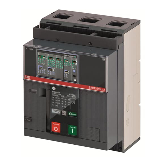
SACE Emax 2
Emax low voltage air circuit-breakers E1.2-E2.2-E4.2-E6.2
Instructions for using Ekip Touch protection trip units
and Accessories.
Related Manuals for ABB SACE Emax 2
Summary of Contents for ABB SACE Emax 2
-
Page 1
DOC. N° 1SDH001316R1002 — ECN000086501 — Rev. A SACE Emax 2 Emax low voltage air circuit-breakers E1.2-E2.2-E4.2-E6.2 Instructions for using Ekip Touch protection trip units and Accessories. -
Page 2
ABB | SACE Emax 2 2 | © 2019 ABB | 1SDH001316R1002 — ECN000086501 — Rev. A… -
Page 3: Table Of Contents
3 — Measurement …………..48 Default ………………49 1 — Ekip TOUCH default parameters ……..49 Management operations …………50 1 — Ekip Touch maintenance and troubleshooting ….50 © 2019 ABB SACE Emax 2 | I 1SDH001316R1002 — ECN000086501 — Rev. A…
-
Page 4
1SDH001316R1002 — ECN000086501 — Rev. A II | © 2019 ABB SACE Emax 2… -
Page 5: Glossary
In the event of an alarm, it commands a TRIP Ekip Touch Trip unit for SACE Emax 2 CBs, equipped with touchscreen display and available in four different versions Trip coil CB opening actuator controlled directly by Trip unit…
-
Page 6: Introduction
ABB | SACE Emax 2 Introduction 1 — Contents Overview This manual describes the characteristics of the Ekip Touch Trip units installed on SACE Emax 2 CBs, among which: general overview: operating conditions consultation of menus for changing parameters and displaying measurements…
-
Page 7: Safety
• anyone who is implementing procedures or using maintenance devices recommended by ABB or not must check carefully that neither their personal safety nor the safety devices are endangered by the installation, operation, maintenance method or by the tools used; contact your nearest ABB representative for further information, explanations or specific problems •…
-
Page 8: Overview Of Ekip Touch
ABB | SACE Emax 2 Overview of Ekip Touch 1 — General characteristics Families SACE Emax 2 can be configured to operate with two Trip unit families: • Ekip Dip with interface via dip-switches • Ekip Touch with touchscreen display Both families provide protection and measuring functions related to signals from the installation and are available in different models and versions.
-
Page 9: Models And Versions
Description Lists of the main characteristics of the protections and measurements of each package are given in the next chapters. A description of the Datalogger and Network Analyzer functions is available in manual 1SDH001330R1002. 7 | © 2019 ABB | 1SDH001316R1002 — ECN000086501 — Rev. A Overview of Ekip Touch | 2 — Models and Versions…
-
Page 10: Accessories And Software
• Embedded ATS For details consult the Technical catalog or the summary documents of each function (page 9). 8 | © 2019 ABB | 1SDH001316R1002 — ECN000086501 — Rev. A Overview of Ekip Touch | 3 — Accessories and software…
-
Page 11
Ekip Touch in your installation: documents NOTE: some of the documents mentioned in the next table refer to SACE Emax 2, but can also be used with SACE Tmax XT7 Ekip Connect 3… -
Page 12
White Paper on ATS systems for applications which require continuity of service (1SDC007115G0202) Handbook General overview of electrical installations (1SDC010002D0206) 10 | © 2019 ABB | 1SDH001316R1002 — ECN000086501 — Rev. A Overview of Ekip Touch | 3 — Accessories and software… -
Page 13: Operating Features
IMPORTANT: if connection is direct, the power supply must be galvanically insulated and provide the insulation characteristics established by standard IEC 60950 (UL 1950) or equivalent. 11 | © 2019 ABB | 1SDH001316R1002 — ECN000086501 — Rev. A Overview of Ekip Touch | 4 — Operating features…
-
Page 14: Interface And Menus
Display The touchscreen display of Ekip Touch is the single-touch, color type. The touchscreen function is active when the unit is on. 12 | © 2019 ABB | 1SDH001316R1002 — ECN000086501 — Rev. A Interface and menus | 1 — Presentation of interface…
-
Page 15
IMPORTANT: only use cables supplied by ABB or with ABB accessories 13 | © 2019 ABB | 1SDH001316R1002 — ECN000086501 — Rev. A Interface and menus | 1 — Presentation of interface… -
Page 16: Navigation
4. access one of the graphic pages: Histograms, Measuring instruments and Measurements 5. access the MENU AREA (level 3) Figure 6 Continued on the next page 14 | © 2019 ABB | 1SDH001316R1002 — ECN000086501 — Rev. A Interface and menus | 2 — Navigation…
-
Page 17
To consult a parameter, it just needs to be selected. Consult the dedicated section for instructions on how to configure and save the parameters (page 24). 15 | © 2019 ABB | 1SDH001316R1002 — ECN000086501 — Rev. A Interface and menus | 2 — Navigation… -
Page 18: Graphic
NOTE: both pages can be set as the main page by pressing HOME, holding it for five seconds and confirming the message on the display 16 | © 2019 ABB | 1SDH001316R1002 — ECN000086501 — Rev. A Interface and menus | 3 — Graphic pages…
-
Page 19
Summary of Load Shedding measurements, if present Ekip Signalling 3T Summary of Ekip Signalling 3T module measurements, if present Continued on the next page 17 | © 2019 ABB | 1SDH001316R1002 — ECN000086501 — Rev. A Interface and menus | 3 — Graphic pages… -
Page 20
Warning, error or prealarm About Timing due to tripped protection The complete list of alarms is given on page 50. 18 | © 2019 ABB | 1SDH001316R1002 — ECN000086501 — Rev. A Interface and menus | 3 — Graphic pages… -
Page 21: Menu
(Set A / Set B) will be available before the list of protections available for LSIG versions available if the presence of sensor S.G.R. has been activated previously 19 | © 2019 ABB | 1SDH001316R1002 — ECN000086501 — Rev. A Interface and menus | 4 — Menu…
-
Page 22
Rc sensor Rc available when type is installed in unit and when presence of has been previously activated in Settings menu 20 | © 2019 ABB | 1SDH001316R1002 — ECN000086501 — Rev. A Interface and menus | 4 — Menu… -
Page 23
Ekip Synchrocheck module is present available if provided for by Trip unit model or if Network Analyzer SW package has been activated 21 | © 2019 ABB | 1SDH001316R1002 — ECN000086501 — Rev. A Interface and menus | 4 — Menu… -
Page 24
(=On) available if provided for by Trip unit model or if relative SW package has been activated available with LSIG versions 22 | © 2019 ABB | 1SDH001316R1002 — ECN000086501 — Rev. A Interface and menus | 4 — Menu… -
Page 25
Trip unit 23 | © 2019 ABB | 1SDH001316R1002 — ECN000086501 — Rev. A Interface and menus | 4 — Menu… -
Page 26: Changing Parameters And Commands
Abort to interrupt the save data process • • Modify to go back to the menus and change the parameter or others Figure 19 24 | © 2019 ABB | 1SDH001316R1002 — ECN000086501 — Rev. A Interface and menus | 5 — Changing parameters and commands…
-
Page 27
• if the Trip unit detects an incorrect condition, the relative details appear on the display and command execution is annulled. WARNING! aborting the programming affects all the parameters modified during the same session 25 | © 2019 ABB | 1SDH001316R1002 — ECN000086501 — Rev. A Interface and menus | 5 — Changing parameters and commands… -
Page 28: Pin And Security
Disabling The PIN code can be disabled by entering its value as: 00000; In this case, the PIN is only required to change the PIN itself in the Settings menu. Recovery if the PIN code is lost, consult document 1SDH001501R0002, available in the ABB website, or contact ABB directly.
-
Page 29: Protections
Description Current Nominal current of the Rating plug Voltage Line-to-line voltage setting Frequency Frequency setting √3 x In x Un Power 27 | © 2019 ABB | 1SDH001316R1002 — ECN000086501 — Rev. A Protections | 1 — Protections — Introduction…
-
Page 30: Standard Protections
; Zone selectivity available with curve t=k; Block configuration available via Ekip Connect the protections do not handle the TRIP, just signaling 28 | © 2019 ABB | 1SDH001316R1002 — ECN000086501 — Rev. A Protections | 2 — Standard Protections…
-
Page 31
I protection. The protection is always active; the trip threshold and time are reserved and defined by ABB. Harmonic distortion Harmonic distortion allows a monitoring alarm to be activated in the case of distorted waveforms; if enabled in the Measurements menu, the unit signals an alarm for peak factors exceeding 2.1. -
Page 32
(for a time set < 5 s) / ± 100 ms (for a time set ≥ 5 s) Continued on the next page 30 | © 2019 ABB | 1SDH001316R1002 — ECN000086501 — Rev. A Protections | 2 — Standard Protections… -
Page 33
± 15 % ± 20 % (60 ms with t4 = instantaneous) ± 15 % ≤ 60 ms Other ± 20 % 31 | © 2019 ABB | 1SDH001316R1002 — ECN000086501 — Rev. A Protections | 2 — Standard Protections… -
Page 34: Voltage Protections
0.3 Un the Trip unit considers a 3% hysteresis for quitting the alarm condition 32 | © 2019 ABB | 1SDH001316R1002 — ECN000086501 — Rev. A Protections | 3 — Voltage protections…
-
Page 35: Voltage Advanced Protections
Ks2 setting must ensure the following limitation: Ks2 * I21 ≥ 0.6 In; parameter Uh2 is available in the Linear mode; the setting must comply with the following limitation: Uh2 > Ul2 33 | © 2019 ABB | 1SDH001316R1002 — ECN000086501 — Rev. A Protections | 4 — Voltage Advanced protections…
-
Page 36: Frequency Protections
32 V with hysteresis at 36 V tolerance valid for frequencies within range: fn ± 2%; a ± 5% tolerance is available for off range frequencies 34 | © 2019 ABB | 1SDH001316R1002 — ECN000086501 — Rev. A Protections | 5 — Frequency protections…
-
Page 37
(TRIP OFF is signaled); the protection is also active for negative active power, but is independent of RP protection (Protection from inverse active power) Continued on the next page 35 | © 2019 ABB | 1SDH001316R1002 — ECN000086501 — Rev. A Protections | 6 — Power protections… -
Page 38: Rocof Protections
The function can be activated and the Set of the main protections configured in the Settings — Double Set menu; the event that determines Set change (from main to secondary) can be programmed in the Advanced — Functions menu. 36 | © 2019 ABB | 1SDH001316R1002 — ECN000086501 — Rev. A Protections | 8 — Adaptive protections…
-
Page 39: Additional Protections And Functions
LOCAL Switch On Changes the configuration, from Remote to Local Settings — Modules — Functions Signaling RESET Reset the contacts of the signalling modules 37 | © 2019 ABB | 1SDH001316R1002 — ECN000086501 — Rev. A Protections | 8 — Adaptive protections…
-
Page 40: Measurements
Histograms, Measuring instruments and Measurement summary pages available by activating the presence of sensor S.G.R or Rc 38 | © 2019 ABB | 1SDH001316R1002 — ECN000086501 — Rev. A Measurements | 1 — Standard Measurements…
-
Page 41: Ekip Measuring Measurements
0.7 % with class 0.2 external transformers without transformers; with transformers, multiply the min and max values for the transformer ratio between primary and secondary voltages 39 | © 2019 ABB | 1SDH001316R1002 — ECN000086501 — Rev. A Measurements | 2 — Ekip Measuring Measurements…
-
Page 42
Reset measurements The Energy RESET command is available in the Energy menu for the purpose of resetting the energy counters (page 21). 40 | © 2019 ABB | 1SDH001316R1002 — ECN000086501 — Rev. A Measurements | 2 — Ekip Measuring Measurements… -
Page 43: Class 1 Power & Energy Metering
CB for the specific purpose of conforming to the characteristics of the package (electronic units and internal current sensors) 41 | © 2019 ABB | 1SDH001316R1002 — ECN000086501 — Rev. A Measurements | 3 — Class 1 Power & Energy Metering…
-
Page 44: Settings
Ekip Touch is supplied with the parameter setting that suits the ordered configuration. 42 | © 2019 ABB | 1SDH001316R1002 — ECN000086501 — Rev. A Settings | 1 — Main settings…
-
Page 45
BLE — Connection security Activation of LV communication requires the Trip unit to be pre-engineered for a wireless connection: security of the data and LV connection between the Trip unit and its device is guaranteed thanks to the ABB EPiC application and the pairing configuration. -
Page 46
(trips or measurements); in the event of date and time glitches, reset and if necessary replace the battery inside Ekip Touch (page 50). 44 | © 2019 ABB | 1SDH001316R1002 — ECN000086501 — Rev. A Settings | 1 — Main settings… -
Page 47: Test
• make sure that the coils are connected to the supply source • release operation is checked by the commands: faults in Ekip Com Actuator or the coils are not detected by the test 45 | © 2019 ABB | 1SDH001316R1002 — ECN000086501 — Rev. A Test | 1 — Test…
-
Page 48
(of the toroid and power supplies of the unit) and that TRIP is accomplished 46 | © 2019 ABB | 1SDH001316R1002 — ECN000086501 — Rev. A Test | 1 — Test… -
Page 49: Accessories
It is installed on a dedicated front connector and is accessible to the user for inspections or replacement following a change of model/size. For further details about the available models, operations and reference documents, consult document 1SDH001330R1002. 47 | © 2019 ABB | 1SDH001316R1002 — ECN000086501 — Rev. A Accessories | 1 — Introduction…
-
Page 50: Measurement
Replacement The Measurement module can be replaced on its Trip unit, for details consult document 1SDH001330R1002. WARNING! if the Class 1 Power & Energy Metering package is present, module replacement will impair the performance values indicated on page 41; consult ABB to assess solutions able to comply with your requirements 48 | ©…
-
Page 51: Default
1-2-3 Local bus Mode Local Language English Password 00001 Home page Histograms Led Alive Disabled View Horizontal Maintenance Test Bus 49 | © 2019 ABB | 1SDH001316R1002 — ECN000086501 — Rev. A Default | 1 — Ekip TOUCH default parameters…
-
Page 52: Management Operations
Fault in Ekip Link module: check for loss of connection with one or more actors Ekip Link Bus (modules) connected to Link Bus Continued on the next page 50 | © 2019 ABB | 1SDH001316R1002 — ECN000086501 — Rev. A Management operations | 1 — Ekip Touch maintenance and troubleshooting…
-
Page 53
IEEE1588 synch Synchronization problem of IEEE 1588 synchronization reference module MAC Address Ekip Com module detected with incorrect / not allowed MAC address, contact ABB. Ekip Installation Installation error between HMI and Mainboard, contact ABB Measuring Install Measurement module (Settings-Circuit breaker-Installation-Measuring-Install) -
Page 54
1SDH000999R0002 and 1SDH001000R0002. NOTE: check error messages on display before consulting the table; if the suggestions given fail to resolve the problem, call the ABB assistance service and provide the report produced by the Ekip Connect software if possible Fault… -
Page 55
Opening data not No auxiliary power supply and/or battery Correct operating condition. displayed 53 | © 2019 ABB | 1SDH001316R1002 — ECN000086501 — Rev. A Management operations | 1 — Ekip Touch maintenance and troubleshooting… -
Page 56
ABB | SACE Emax 2 54 | © 2019 ABB | 1SDH001316R1002 — ECN000086501 — Rev. A Management operations | 1 — Ekip Touch maintenance and troubleshooting…
- Manuals
- Brands
- ABB Manuals
- Circuit breakers
- SACE Emax 2
- Manual
-
Contents
-
Table of Contents
-
Bookmarks
Quick Links
DOC. N° 1SDH001316R1002 — ECN000086501 — Rev. A
SACE Emax 2
Emax low voltage air circuit-breakers E1.2-E2.2-E4.2-E6.2
Instructions for using Ekip Touch protection trip units
and Accessories.
Related Manuals for ABB SACE Emax 2
Summary of Contents for ABB SACE Emax 2
-
Page 1
DOC. N° 1SDH001316R1002 — ECN000086501 — Rev. A SACE Emax 2 Emax low voltage air circuit-breakers E1.2-E2.2-E4.2-E6.2 Instructions for using Ekip Touch protection trip units and Accessories. -
Page 2
ABB | SACE Emax 2 2 | © 2019 ABB | 1SDH001316R1002 — ECN000086501 — Rev. A… -
Page 3: Table Of Contents
3 — Measurement …………..48 Default ………………49 1 — Ekip TOUCH default parameters ……..49 Management operations …………50 1 — Ekip Touch maintenance and troubleshooting ….50 © 2019 ABB SACE Emax 2 | I 1SDH001316R1002 — ECN000086501 — Rev. A…
-
Page 4
1SDH001316R1002 — ECN000086501 — Rev. A II | © 2019 ABB SACE Emax 2… -
Page 5: Glossary
In the event of an alarm, it commands a TRIP Ekip Touch Trip unit for SACE Emax 2 CBs, equipped with touchscreen display and available in four different versions Trip coil CB opening actuator controlled directly by Trip unit…
-
Page 6: Introduction
ABB | SACE Emax 2 Introduction 1 — Contents Overview This manual describes the characteristics of the Ekip Touch Trip units installed on SACE Emax 2 CBs, among which: general overview: operating conditions consultation of menus for changing parameters and displaying measurements…
-
Page 7: Safety
• anyone who is implementing procedures or using maintenance devices recommended by ABB or not must check carefully that neither their personal safety nor the safety devices are endangered by the installation, operation, maintenance method or by the tools used; contact your nearest ABB representative for further information, explanations or specific problems •…
-
Page 8: Overview Of Ekip Touch
ABB | SACE Emax 2 Overview of Ekip Touch 1 — General characteristics Families SACE Emax 2 can be configured to operate with two Trip unit families: • Ekip Dip with interface via dip-switches • Ekip Touch with touchscreen display Both families provide protection and measuring functions related to signals from the installation and are available in different models and versions.
-
Page 9: Models And Versions
Description Lists of the main characteristics of the protections and measurements of each package are given in the next chapters. A description of the Datalogger and Network Analyzer functions is available in manual 1SDH001330R1002. 7 | © 2019 ABB | 1SDH001316R1002 — ECN000086501 — Rev. A Overview of Ekip Touch | 2 — Models and Versions…
-
Page 10: Accessories And Software
• Embedded ATS For details consult the Technical catalog or the summary documents of each function (page 9). 8 | © 2019 ABB | 1SDH001316R1002 — ECN000086501 — Rev. A Overview of Ekip Touch | 3 — Accessories and software…
-
Page 11
Ekip Touch in your installation: documents NOTE: some of the documents mentioned in the next table refer to SACE Emax 2, but can also be used with SACE Tmax XT7 Ekip Connect 3… -
Page 12
White Paper on ATS systems for applications which require continuity of service (1SDC007115G0202) Handbook General overview of electrical installations (1SDC010002D0206) 10 | © 2019 ABB | 1SDH001316R1002 — ECN000086501 — Rev. A Overview of Ekip Touch | 3 — Accessories and software… -
Page 13: Operating Features
IMPORTANT: if connection is direct, the power supply must be galvanically insulated and provide the insulation characteristics established by standard IEC 60950 (UL 1950) or equivalent. 11 | © 2019 ABB | 1SDH001316R1002 — ECN000086501 — Rev. A Overview of Ekip Touch | 4 — Operating features…
-
Page 14: Interface And Menus
Display The touchscreen display of Ekip Touch is the single-touch, color type. The touchscreen function is active when the unit is on. 12 | © 2019 ABB | 1SDH001316R1002 — ECN000086501 — Rev. A Interface and menus | 1 — Presentation of interface…
-
Page 15
IMPORTANT: only use cables supplied by ABB or with ABB accessories 13 | © 2019 ABB | 1SDH001316R1002 — ECN000086501 — Rev. A Interface and menus | 1 — Presentation of interface… -
Page 16: Navigation
4. access one of the graphic pages: Histograms, Measuring instruments and Measurements 5. access the MENU AREA (level 3) Figure 6 Continued on the next page 14 | © 2019 ABB | 1SDH001316R1002 — ECN000086501 — Rev. A Interface and menus | 2 — Navigation…
-
Page 17
To consult a parameter, it just needs to be selected. Consult the dedicated section for instructions on how to configure and save the parameters (page 24). 15 | © 2019 ABB | 1SDH001316R1002 — ECN000086501 — Rev. A Interface and menus | 2 — Navigation… -
Page 18: Graphic
NOTE: both pages can be set as the main page by pressing HOME, holding it for five seconds and confirming the message on the display 16 | © 2019 ABB | 1SDH001316R1002 — ECN000086501 — Rev. A Interface and menus | 3 — Graphic pages…
-
Page 19
Summary of Load Shedding measurements, if present Ekip Signalling 3T Summary of Ekip Signalling 3T module measurements, if present Continued on the next page 17 | © 2019 ABB | 1SDH001316R1002 — ECN000086501 — Rev. A Interface and menus | 3 — Graphic pages… -
Page 20
Warning, error or prealarm About Timing due to tripped protection The complete list of alarms is given on page 50. 18 | © 2019 ABB | 1SDH001316R1002 — ECN000086501 — Rev. A Interface and menus | 3 — Graphic pages… -
Page 21: Menu
(Set A / Set B) will be available before the list of protections available for LSIG versions available if the presence of sensor S.G.R. has been activated previously 19 | © 2019 ABB | 1SDH001316R1002 — ECN000086501 — Rev. A Interface and menus | 4 — Menu…
-
Page 22
Rc sensor Rc available when type is installed in unit and when presence of has been previously activated in Settings menu 20 | © 2019 ABB | 1SDH001316R1002 — ECN000086501 — Rev. A Interface and menus | 4 — Menu… -
Page 23
Ekip Synchrocheck module is present available if provided for by Trip unit model or if Network Analyzer SW package has been activated 21 | © 2019 ABB | 1SDH001316R1002 — ECN000086501 — Rev. A Interface and menus | 4 — Menu… -
Page 24
(=On) available if provided for by Trip unit model or if relative SW package has been activated available with LSIG versions 22 | © 2019 ABB | 1SDH001316R1002 — ECN000086501 — Rev. A Interface and menus | 4 — Menu… -
Page 25
Trip unit 23 | © 2019 ABB | 1SDH001316R1002 — ECN000086501 — Rev. A Interface and menus | 4 — Menu… -
Page 26: Changing Parameters And Commands
Abort to interrupt the save data process • • Modify to go back to the menus and change the parameter or others Figure 19 24 | © 2019 ABB | 1SDH001316R1002 — ECN000086501 — Rev. A Interface and menus | 5 — Changing parameters and commands…
-
Page 27
• if the Trip unit detects an incorrect condition, the relative details appear on the display and command execution is annulled. WARNING! aborting the programming affects all the parameters modified during the same session 25 | © 2019 ABB | 1SDH001316R1002 — ECN000086501 — Rev. A Interface and menus | 5 — Changing parameters and commands… -
Page 28: Pin And Security
Disabling The PIN code can be disabled by entering its value as: 00000; In this case, the PIN is only required to change the PIN itself in the Settings menu. Recovery if the PIN code is lost, consult document 1SDH001501R0002, available in the ABB website, or contact ABB directly.
-
Page 29: Protections
Description Current Nominal current of the Rating plug Voltage Line-to-line voltage setting Frequency Frequency setting √3 x In x Un Power 27 | © 2019 ABB | 1SDH001316R1002 — ECN000086501 — Rev. A Protections | 1 — Protections — Introduction…
-
Page 30: Standard Protections
; Zone selectivity available with curve t=k; Block configuration available via Ekip Connect the protections do not handle the TRIP, just signaling 28 | © 2019 ABB | 1SDH001316R1002 — ECN000086501 — Rev. A Protections | 2 — Standard Protections…
-
Page 31
I protection. The protection is always active; the trip threshold and time are reserved and defined by ABB. Harmonic distortion Harmonic distortion allows a monitoring alarm to be activated in the case of distorted waveforms; if enabled in the Measurements menu, the unit signals an alarm for peak factors exceeding 2.1. -
Page 32
(for a time set < 5 s) / ± 100 ms (for a time set ≥ 5 s) Continued on the next page 30 | © 2019 ABB | 1SDH001316R1002 — ECN000086501 — Rev. A Protections | 2 — Standard Protections… -
Page 33
± 15 % ± 20 % (60 ms with t4 = instantaneous) ± 15 % ≤ 60 ms Other ± 20 % 31 | © 2019 ABB | 1SDH001316R1002 — ECN000086501 — Rev. A Protections | 2 — Standard Protections… -
Page 34: Voltage Protections
0.3 Un the Trip unit considers a 3% hysteresis for quitting the alarm condition 32 | © 2019 ABB | 1SDH001316R1002 — ECN000086501 — Rev. A Protections | 3 — Voltage protections…
-
Page 35: Voltage Advanced Protections
Ks2 setting must ensure the following limitation: Ks2 * I21 ≥ 0.6 In; parameter Uh2 is available in the Linear mode; the setting must comply with the following limitation: Uh2 > Ul2 33 | © 2019 ABB | 1SDH001316R1002 — ECN000086501 — Rev. A Protections | 4 — Voltage Advanced protections…
-
Page 36: Frequency Protections
32 V with hysteresis at 36 V tolerance valid for frequencies within range: fn ± 2%; a ± 5% tolerance is available for off range frequencies 34 | © 2019 ABB | 1SDH001316R1002 — ECN000086501 — Rev. A Protections | 5 — Frequency protections…
-
Page 37
(TRIP OFF is signaled); the protection is also active for negative active power, but is independent of RP protection (Protection from inverse active power) Continued on the next page 35 | © 2019 ABB | 1SDH001316R1002 — ECN000086501 — Rev. A Protections | 6 — Power protections… -
Page 38: Rocof Protections
The function can be activated and the Set of the main protections configured in the Settings — Double Set menu; the event that determines Set change (from main to secondary) can be programmed in the Advanced — Functions menu. 36 | © 2019 ABB | 1SDH001316R1002 — ECN000086501 — Rev. A Protections | 8 — Adaptive protections…
-
Page 39: Additional Protections And Functions
LOCAL Switch On Changes the configuration, from Remote to Local Settings — Modules — Functions Signaling RESET Reset the contacts of the signalling modules 37 | © 2019 ABB | 1SDH001316R1002 — ECN000086501 — Rev. A Protections | 8 — Adaptive protections…
-
Page 40: Measurements
Histograms, Measuring instruments and Measurement summary pages available by activating the presence of sensor S.G.R or Rc 38 | © 2019 ABB | 1SDH001316R1002 — ECN000086501 — Rev. A Measurements | 1 — Standard Measurements…
-
Page 41: Ekip Measuring Measurements
0.7 % with class 0.2 external transformers without transformers; with transformers, multiply the min and max values for the transformer ratio between primary and secondary voltages 39 | © 2019 ABB | 1SDH001316R1002 — ECN000086501 — Rev. A Measurements | 2 — Ekip Measuring Measurements…
-
Page 42
Reset measurements The Energy RESET command is available in the Energy menu for the purpose of resetting the energy counters (page 21). 40 | © 2019 ABB | 1SDH001316R1002 — ECN000086501 — Rev. A Measurements | 2 — Ekip Measuring Measurements… -
Page 43: Class 1 Power & Energy Metering
CB for the specific purpose of conforming to the characteristics of the package (electronic units and internal current sensors) 41 | © 2019 ABB | 1SDH001316R1002 — ECN000086501 — Rev. A Measurements | 3 — Class 1 Power & Energy Metering…
-
Page 44: Settings
Ekip Touch is supplied with the parameter setting that suits the ordered configuration. 42 | © 2019 ABB | 1SDH001316R1002 — ECN000086501 — Rev. A Settings | 1 — Main settings…
-
Page 45
BLE — Connection security Activation of LV communication requires the Trip unit to be pre-engineered for a wireless connection: security of the data and LV connection between the Trip unit and its device is guaranteed thanks to the ABB EPiC application and the pairing configuration. -
Page 46
(trips or measurements); in the event of date and time glitches, reset and if necessary replace the battery inside Ekip Touch (page 50). 44 | © 2019 ABB | 1SDH001316R1002 — ECN000086501 — Rev. A Settings | 1 — Main settings… -
Page 47: Test
• make sure that the coils are connected to the supply source • release operation is checked by the commands: faults in Ekip Com Actuator or the coils are not detected by the test 45 | © 2019 ABB | 1SDH001316R1002 — ECN000086501 — Rev. A Test | 1 — Test…
-
Page 48
(of the toroid and power supplies of the unit) and that TRIP is accomplished 46 | © 2019 ABB | 1SDH001316R1002 — ECN000086501 — Rev. A Test | 1 — Test… -
Page 49: Accessories
It is installed on a dedicated front connector and is accessible to the user for inspections or replacement following a change of model/size. For further details about the available models, operations and reference documents, consult document 1SDH001330R1002. 47 | © 2019 ABB | 1SDH001316R1002 — ECN000086501 — Rev. A Accessories | 1 — Introduction…
-
Page 50: Measurement
Replacement The Measurement module can be replaced on its Trip unit, for details consult document 1SDH001330R1002. WARNING! if the Class 1 Power & Energy Metering package is present, module replacement will impair the performance values indicated on page 41; consult ABB to assess solutions able to comply with your requirements 48 | ©…
-
Page 51: Default
1-2-3 Local bus Mode Local Language English Password 00001 Home page Histograms Led Alive Disabled View Horizontal Maintenance Test Bus 49 | © 2019 ABB | 1SDH001316R1002 — ECN000086501 — Rev. A Default | 1 — Ekip TOUCH default parameters…
-
Page 52: Management Operations
Fault in Ekip Link module: check for loss of connection with one or more actors Ekip Link Bus (modules) connected to Link Bus Continued on the next page 50 | © 2019 ABB | 1SDH001316R1002 — ECN000086501 — Rev. A Management operations | 1 — Ekip Touch maintenance and troubleshooting…
-
Page 53
IEEE1588 synch Synchronization problem of IEEE 1588 synchronization reference module MAC Address Ekip Com module detected with incorrect / not allowed MAC address, contact ABB. Ekip Installation Installation error between HMI and Mainboard, contact ABB Measuring Install Measurement module (Settings-Circuit breaker-Installation-Measuring-Install) -
Page 54
1SDH000999R0002 and 1SDH001000R0002. NOTE: check error messages on display before consulting the table; if the suggestions given fail to resolve the problem, call the ABB assistance service and provide the report produced by the Ekip Connect software if possible Fault… -
Page 55
Opening data not No auxiliary power supply and/or battery Correct operating condition. displayed 53 | © 2019 ABB | 1SDH001316R1002 — ECN000086501 — Rev. A Management operations | 1 — Ekip Touch maintenance and troubleshooting… -
Page 56
ABB | SACE Emax 2 54 | © 2019 ABB | 1SDH001316R1002 — ECN000086501 — Rev. A Management operations | 1 — Ekip Touch maintenance and troubleshooting…
Emax 2 идеально интегрируется в любые проекты: как в стандартные электроустановки, так и в комплексные автоматизированные системы. Воздушные автоматические выключатели Emax 2 были разработаны с целью максимального повышения эффективности работы электроустановки. Это единственный автоматический выключатель, который не только обеспечивает защитные функции, но и способен снизить потребление электроэнергии с учетом требований пользователя, что приводит к значительному сокращению потерь.
- Эффективность и контроль
Эксклюзивная технология управления нагрузкой позволяет добиваться существенного сокращения энергопотребления и уменьшения расходов на электроэнергию. Встроенные мультиметры измеряют напряжение с погрешностью 0,5 %, протекающий ток с погрешностью 1 % и мощность с погрешностью 2 %. Они предназначены для мониторинга энергопотребления даже в дистанционном режиме.
- Совместимость
Автоматические выключатели Emax 2 идеально подходят для создания современного НКУ. Новые возможности позволяют обеспечить передачу данных по самым современным протоколам связи, включая протокол для сетей Smart Grid — МЭК 61850.
- Исполнение
Автоматические выключатели Emax 2 представлены в 4х типоразмерах, сочетающих в себе высокие технические характеристики и компактные габаритные размеры, оптимизированные для применений совместно с системой оболочек System pro E power. Компактные габаритные размеры аппаратов и новая конструкция силовых выводов позволяют добиться уменьшения занимаемой площади в щитовой до 25%.
- Простота и безопасность использования
Серия Emax 2 отличается простотой и удобством выбора при проектировании, сборке НКУ и эксплуатации в электроустановке, в сочетании с существенно возросшим функционалом аппаратов. Экономьте время сборки НКУ при использовании Emax 2: время на подключение дополнительных цепей сокращено на 15 %; время, затрачиваемое на установку дополнительных аксессуаров, уменьшено на 30 %. Сочетание систем анализа качества питающей сети, сигнализации и записи аварийных событий, самодиагностики, русскоязычного меню и отображения информации делает Emax 2 максимально удобным для конечного пользователя в процессе эксплуатации.
Инструменты и поддержка
Серии для различных сегментов
Другие предложения
-
Отправьте запрос и мы свяжемся с вами
Свяжитесь с нами
Doc. N.° 1SDH002037A1001 — ECN000108222 — Rev. C
Emax 2
Retrotting tra interruttori estraibili Emax 2 E2.2 — E4.2 — E6.2 ed Entelliguard G Env1 — Env2 — Env3
Retrofitting kit between Emax 2 E2.2 — E4.2 — E6.2 and Entelliguard G Env1 — Env2 — Env3 Withdrawble circuit breakers
Nachrüstung zwischen ausfahrbaren Leistungsschaltern Emax 2 E2.2 — E4.2 — E6.2 und Entelliguard G Env1 — Env2 — Env3
Reconguration entre les disjoncteurs Emax 2 E2.2 -E4.2 — E6.2 et Entelliguard G Env1 — Env2 — Env3 débrochables
Reequipamiento entre los interruptores de extracción Emax 2 E2.2 — E4.2 — E6.2 y Entelliguard G Env1 — Env2 — Env3
Il presente kit di retrofitting, è costruito per la sostituzione totale di interruttori
aperti
Entelliguard G Env1 — Env2 — Env3
estraibile di più moderna fattura tipo Emax 2 di medesima taglia, senza dover
eseguire alcuna modifica alle parti attive del quadro.
E’ garantita la totale corrispondenza delle caratteristiche elettriche (corrente
nominale e potere di interruzione) a condizione che:
1.La scelta sia effettuata in conformità a quanto riportato nei cataloghi tecnici
relativi ai prodotti di retrofitting.
2.L’interruttore
Entelliguard G
proprio manuale di installazione, rispettando le distanze di isolamento verso
massa, il dimensionamento delle sbarre di connessione, il posizionamento del
primo setto di ancoraggio.
IMPORTANTE
L’attività di retrofitting consente una sostituzione di un dispositivo di comando
e protezione divenuto obsoleto ma non di alterare in maniera alcuna i dati di
progetto originali del quadro esistente. Qualora il nuovo interruttore
presentasse dati di targa superiori, i kit di retrofitting sono dimensionati per le
prestazioni del vecchio dispositivo.
Per ulteriori chiarimenti contattare ABB.
Attenzione Istruzioni riguardanti il solo assemblaggio del kit di retrotitting, non
sono da intendersi come sostitutive del manuale di installazione, uso e
manutenzione del nuovo interruttore Emax 2.
MESSA IN SICUREZZA DELL’IMPIANTO
A) A garanzia dell’incolumità del personale addetti all’installazione del kit,
prima di operare la sostituzione dell’interruttore, si raccomanda di seguire,
scrupolosamente, le seguenti azioni:
— Mettere fuori servizio il quadro ospitante
— Portare l’interruttore da sostituire in posizione di aperto e molle scariche
— Disconnettere le applicazioni ausiliarie
— Prima di estrarre l’apparecchio, controllare nuovamente il fuori servizio
dell’utenza
B) Smantellare completamente il vecchio interruttore conservando le viti di
connessione
dei terminali del vecchio interruttore
barratura del quadro.
con interruttori aperti in esecuzione
da sostituire sia installato in conformità al
Entelliguard G
This retrofitting kit allows
be fully replaced with the more modern Emax 2 plug-in air circuit-breakers of
the same size without having to modify the live parts of the switchgear in any
way.
Full correspondence of the electrical characteristics is guaranteed (rated
current and breaking capacity) so long as:
1.The kit is chosen in accordance with the indications in the technical
catalogues dedicated to retrofitting products.
2.The
Entelliguard G
circuit-breaker to be replaced has been installed in
compliance with the instructions in the relative installation manual, and with
the specified insulation clearance towards earth, connection busbar size and
position of the first anchor plate.
IMPORTANT
Retrofitting allows an obsolete control and protection device to be replaced,
but does not allow the data of the original project of the existing switchboard to
be altered in any way. If the rating plate data of the new circuit-breaker are
higher, the retrofitting kits are sized for the performance of the old device.
Consult ABB for further details.
Warning The instructions concern the sole assembly of the retrofitting kit.
They do not substitute the instructions in the installation, operation and
maintenance manual of the new Emax 2 circuit-breaker.
SETTING THE INSTALLATION IN SAFE CONDITIONS
A) To ensure that the persons who install the kit work in safe conditions, strictly
comply with the following instructions before replacing the circuit-breaker:
— Close down the switchboard in which the circuit-breaker is to be installed.
— Set the old circuit-breaker to the open position with the springs unloaded.
— Disconnect the auxiliary circuit applications.
— Check to make sure that the user is disconnected before removing the
device.
B) Completely disassemble the old circuit-breaker, but keep the screws that
connect the terminals of the old
alla
switchboard bars.
Entelliguard G Env1 — Env2 — Env3
Entelliguard G
circuit-breaker to the
circuit-breakers to
Предложите, как улучшить StudyLib
(Для жалоб на нарушения авторских прав, используйте
другую форму
)
Ваш е-мэйл
Заполните, если хотите получить ответ
Оцените наш проект
1
2
3
4
5
ABB SACE Emax 2: Available Instructions
Note for Owners:
Guidesimo.com webproject is not a service center of ABB trademark and does not carries out works for diagnosis and repair of faulty ABB SACE Emax 2 equipment. For quality services, please contact an official service center of ABB company. On our website you can read and download documentation for your ABB SACE Emax 2 device for free and familiarize yourself with the technical specifications of device.
-
ABB 5HK Series
IB6.2.1.7DInstallation/MaintenanceInstructionsMedium-VoltagePowerCircuitBreakersType5HK1200thru3000Amperes5000VoltsJLllllMllllABBPowerDistribution,Inc.CircuitBreakerDivisionASEABROWNBOVERICourtesy of NationalSwitchgear.com …
5HK Series Circuit breakers, 16
-
Toshiba HV6FS
Document: GF07Z303 Rev 1INSTRUCTION MANUALINSTALLATION — OPERATION — MAINTENANCEHV6FS Vacuum Circuit Breakers – Fixed Type4.8 & 7.2kV Voltage Classes(Fast Closing)APPLICABLE MODEL NUMBERS:(Motor Operation Types)HV6FS-MUHV6FS-MLIssued: 8/2004Phone: 800.894.0412 — Fax: 888.723.4773 — Web: www.clrwtr.com — Email: [email protected] …
HV6FS Circuit breakers, 39
-
Doepke DFS 2
min. 50 V AC zwischen zwei aktiven Leitern zu überprüfen. Steht diese Spannung am Schalter an und leuchtet die LED nicht, so ist der Fehlerstromschutzschalter auszutauschen. Die Isolationsprüfung ist mit Prüfgeräten gemäß der DIN EN 61557-2 auszuführen. Für eine einfache Durchführung der Isolationsprüfung der elektrischen Anlage empfehlen wir die Einspeisung bei Scha …
DFS 2 Circuit breakers, 2
-
ABB SACE Emax 2
E1.2SACE Emax 2LEGGERE ATTENTAMENTE IL DOCUMENTO RH0100003 PRIMA DI PROCEDEREREAD CAREFULLY THE DOCUMENT RH0100003 BEFORE PROCEEDINGKit viti di fissaggio (50pz) — E1.2Fixing screws kit (50pcs) — E1.2Befestigungsschrauben (50 Stück) — E1.2Vis de fixation (50pcs) — E1.2Tornillos de fijación (50 piezas) — E1.2Doc. N.° 1SDH001399R0922 — L8926OKOK12 2 1IFISSAGGIO A PARETEWA …
SACE Emax 2 Industrial Electrical, 4
-
Allen-Bradley 140G Series
Phase barriers 140G-G, 140G-H, 140G-I, 140G-JSeparatori di fase Trennwande zwischen den Phasen Sèparateurs de phase Separadores de fase WARNING: To prevent electrical shock, disconnect from power source before installing or servicing. Install in suitable enclosure. Keep free from contaminants. (Follow NFPA70E requirements).AVVERTENZA: Per prevenire infortuni, togliere tensione prima dell&ap …
140G Series Circuit breakers, 3
-
GE Spectra Series
gSpectra Series™ Power PanelboardsType ANKN Neutrals (Model 1)WARNING: Danger of electrical shock or injury.Turn OFF power ahead of the panelboard orswitchboard before working inside theequipment or removing any component .Equipment is to be installed and maintained byproperly trained and qualified personnel only.InstallationIf a bonding strap is required for service, begin with step 1.I …
Spectra Series Industrial Electrical, 2
-
GE AKR-4-30
� …
AKR-4-30 Relays, 32
-
Meiji GFCI
Installing and testing GFCI Receptacle Please read this leaflet completely before getting started 1. What is a GFCI? A GFCI receptacle is different from conventional receptacle. In the event of a ground fault, a GFCI will trip and quickly stop the flow of electricity to prevent serious injury. Definition of Ground fault: Instead of following its normal safe path, electricity pas …
GFCI Circuit breakers, 9
-
LS Industrial Systems Susol Series
Leader in Electrics & AutomationSuper SolutionAir Circuit Breakers Technical CatalogSuper SolutionMeta SolutionAir Circuit Breakers Technical CatalogTechnical Catalog for Susol&Metasol ACB 2007.07 / (01) 2007.07 HUMANPOWER��HEAD OFFICEYonsei Jaedan Severance Bldg., 84-11, Namdaemunro 5-ga, Jung-gu,Seoul 100-753, KoreaTel. (82-2)2034-4870 Fax. (82-2)2034-4713��Cheong-Ju PlantCh …
Susol Series Circuit breakers, 156
-
GE EntelliGuard GBKRKR
1 Introduction Key Interlock Kit: The breaker key lock is an optional accessory, which will keep the breaker in trip free state while locked. Maximum 4 keys of Ronis/Profalux or Kirk type can be used. All EntelliGuard Devices can be equipped with one of the three locks, that when fitted as indicated allow the use of one to four key locks that lock the device in its open position. …
EntelliGuard GBKRKR Circuit breakers, 4
-
ABB SACE Emax 2
E1.2 — XT7Doc. N.° 1SDH000999R0528 — ECN000131197 — Rev. BMeasurement Enabler/Measurement Enabler with voltage socket — E1.2 — XT7SACE Emax 2 — Tmax XTInternal sockets IV with external Y connectionInternal sockets IVExternal sockets III/IVA1FInternal sockets IV Neutral on the rightOnly with code: 1SDA076244R1 — E1.2/XT7 voltage socket for neutral on the right sideBOTTOMTOPTOP BOTTOMA2B1CD1 D2Hx2I …
SACE Emax 2 Circuit breakers, 18
-
Siemens 5ST303 Series
Arbeitsstromauslöser / UnterspannungsauslöserShunt trip / Undervoltage ReleaseDéclencheur courant de travail / Déclencheur basse tensionBobina de disparo / Disparadores de mínima tensiónBobina a lancio di corrente / Sganciatore di minima tensioneDisparador de corrente de trabalho / Disparador de subtensãoAnma akımı deklanşörü / Düşük Gerilim RölesiРасцепитель / Расц� …
5ST303 Series Circuit breakers, 4
-
ABB AF40
Contactors AF and accessoriesSchütze AF und ZubehörContacteurs AF et accessoiresKontaktorer AF och tillbehörContattori AF e accessori Contactores AF y accesoriosAFABB France3, rue Jean Perrin69680 Chassieu / Francewww.abb.com/lowvoltage1SBC101036M6801 — 01/16AF40…96, CA4, CAL4, CAT4, CC4Operating instructionsBetriebsanleitungNotice d’instructionInstruktionIstruzioni tecnicheInstrucciones …
AF40 Circuit breakers, 2
-
Camtec ESB101
ESB101(R2) MANUAL Camtec Power Supplies GmbH — Gewerbestrasse 30 — DE-76327 Pfinztal / Germany P.1/7 (06/2016.02.4) Phone +49 (721) 46596-0 — Fax +49 (721) 46596-77 – www.camtec-gmbh.com — [email protected] (Subject to alterations. This product is not designed to be used in applications such as life support systems wherein a failure or malfunction could result in …
ESB101 Circuit breakers, 7
-
Siemens 3VA25-JP Series
L1V30373480002-07sOperating Instructions Betriebsanleitung Notice d’utilisation Instructivo Istruzioni operativeInstruções de Serviço İşletme kılavuzu Руководство по эксплуатации Instrukcja obsługi 使用说明ENDANGERHazardous voltage. Will cause death or serious injury. Turn off and lock out all power supplying this device before working on this device. Repla …
3VA25-JP Series Circuit breakers, 15
-
Allen-Bradley 140G-M-NVM Series
Bul. 140G/140MG140G-M-RMX, 140G-M-NVM_, 140G-M-RVM_, 140G-N7, 140G-N8 PN-258433DIR 1000479R0612 (Version 01)Installation — Installazione — Instalación Instalação — — WARNING: To prevent electrical shock, disconnect from power source before installing or servicing. Install in suitable enclosure. Keep free from contaminants. (Follow NFPA70E requirements).AVVERTENZA: Pe …
140G-M-NVM Series Circuit breakers, 6
-
Eaton Series NRX
Instruction Leaet IL0131123ENEffective February 2016ContentsDescription PageGeneral information ……………………2Instructions to assemble ………………..4Installation instructions for Series NRX Type NF bus extension kit for 65 kA fixed front connect breaker Instructions apply to:Series NRX Type NF frame (front connect) ULT 489 …
Series NRX Circuit breakers, 8
-
Vertical Power VP-X
1 VP#X%Configurator%Release%Notes%As%of%version%1.6%(May%13,%2013)%%This%document%updated%October%31,%2013% Contents 1.! Models………………………………………………………………………………………………………………………1!2.! Updating the VP-X Pro and Sport firmware (Automatic) ………………………………………………..1!3.! Software Upgrade …
VP-X Circuit breakers, 18
-
LEGRAND DPX
•Notice de montage•Instruction sheet• Anweisungen • Hoja de instrucciones•Foglio istruzioni •Folha de instruções•Bycnherwbb•Instrukcje montażu•Bilgi broflürü02/2009-01 GFY3466A®•Disjoncteurs débrochables•Draw-out circuit breakers•Herausnehmbare Selbstschalter •Interruptores automáticos extraíbles•Interruttori automatici estraibili•Disjuntores extraíveis� …
DPX Circuit breakers, 20
-
Siemens 3RV1 Series
Phasentrennwände Phase barriers Séparateurs de phases Paredes separadoras de fase Separatori di fase Paredes de separação de fases Faz ayιrma plakasι фазовая перегородка 相间隔板 3RV1Last update: 01 January 2008A5E01621444-01Bestell-Nr. / Order No.: 3ZX1012-0RV10-8GA13RV1985-5GA0EN IEC 60947-2Technical Assistance: Telephone: +49 (0) 911-895-5900 (8°° — 17°° CET) …
3RV1 Series Industrial Equipment, 2
-
Eaton Cutler-Hammer VCP-WR Series 18
I.B. 8295A61H03Effective 7/97Cutler-HammerInstructions for the Use, Operation and Maintenance of TheRed Line Type VCP-WR Vacuum Circuit Breaker ElementsVCP-WR Series 29VCP-WR Series 20VCP-WR Series 18 …
Cutler-Hammer VCP-WR Series 18 Circuit breakers, 63
-
Murr Elektronik 85057
-(1) AllgemeinesDas Netzgerät enthält viele Besonderheiten, die bei Industrienetzgeräten zuvor nicht gegeben waren. Das Gerät ist so konstruiert,daß es die üblichen Störaussendung im Wohnbereich ausgleicht und die Störfestigkeit im Industriebereich garantiert.Das Netzgerät hat die positive Eigenschaft, größere Anlauf- und Kurzschlußströme zu liefern, so daß auch bestimmteSicherungsau …
85057 Circuit breakers, 4
-
CHINT OUVT-1
NO:2020.04IEC 60947-5-1OUVT-1Mounting Instructions PaigaldusjuhisedИInstrukcja montażuMontageanleitungИнструкция по монтажуInstructions de montageAsennus-ja käyttöohjeetInstruções de montagemMonteringsveiledningMontážní návodIstruzioni di montaggioнструкции за монтажInstrucciones de montajeЩодо монтуванняMontaj TalimatlarıΟδηγίες …
OUVT-1 Circuit breakers, 6
-
Westinghouse DB-75
InstructionsforTypesDB-75,DB-100andDBF-40AirCircuitBreakers600VoltsA-C250VoltsD-CContinuousCurrentRatingDB-75DB-1002,000Amperes2,500Amperes3,000Amperes4,000Amperes5,000Amperes[D-C6,000Amperes(OnlyWestinghouseElectricCorporationSwitchgearDivision,EastPittsburgh,Pa.I.B.33-850-4&5E,EffectiveSeptember,1976.SupersedesI.B.33-850-4&5D,November,1966.Courtesy of NationalSwitchgear.com …
DB-75 Circuit breakers, 36
-
ABB SACE Emax 2
E1.2-E2.2-E4.2-E6.2Sganciatore di protezione Ekip — E1.2-E2.2-E4.2-E6.2Ekip protection release — E1.2-E2.2-E4.2-E6.2 Schutzauslöser Ekip — E1.2-E2.2-E4.2-E6.2Déclencheur de protection Ekip — E1.2-E2.2-E4.2-E6.2Relé de protección Ekip — E1.2-E2.2-E4.2-E6.2SACE Emax 2Doc. N.° 1SDH001000R0508 — ECN000078285 — Rev. B12OKOK12 2 1Ekip DipEkip Touch/131/3//Ekip LCD//31CLICK …
SACE Emax 2 Circuit breakers, 7
-
Eaton Crouse-hinds series
DOCUMENT 1222 REVISION A July 22, 2019 Instruction Manual PRO Power Switchgear Constant Current Regulator, FAA L-828/L-829 Series 82_SGSPR-480 -_ _ — _ — _ Crouse-Hinds By EATON 1200 Kennedy Road Windsor, CT 06095 Copyright © 2019 Cooper Technologies Company …
Crouse-hinds series Controller, 82
-
ABB S800U
2CCC413015M0403S800U This document contains instructions for the installation and operation of S800 products, manufactured by ABB.Before installing this equipment read this instruction carefully. UNPACKING AND INSPECTIONUnpack the breaker and inspect it for any shipping damage. Insure the breaker has the proper ampere, voltage and interrupting ratings for the application. Also check breake …
S800U Circuit breakers, 2
-
Westinghouse DBN-1016
( NAVSHIPS 362-2189 SWITCHBOARD Technical Manual PART Z CHAPTER 3B NAVY TYPE ACB-1600HR CIRCUIT BREAKER WESTINGHOUSE TYPE DBN-1016 BEMOVABLE ASSEMBLY 1600-AMPEBE FBAME SIZE STANDABDIZED DIMENSIONS WESTINGHOUSE ELECTRIC CORPORATION EAST PITTSBURGH, PA., U. S. A. TECHNICAL MANUAL 32-855-3Cl BUREAU OF SHIPS • NAVY DEPARTMENT • FEBRUARY, 1960 …
DBN-1016 Circuit breakers, 47
Popular Circuit breakers User Guides:
Предложите, как улучшить StudyLib
(Для жалоб на нарушения авторских прав, используйте
другую форму
)
Ваш е-мэйл
Заполните, если хотите получить ответ
Оцените наш проект
1
2
3
4
5
ABB SACE Emax 2 Circuit breakers PDF User Guides and Manuals for Free Download: Found (33) Manuals for ABB SACE Emax 2 Device Model (Owner’s Manual, Instructions Manual)
More Circuit breakers Device Models:
-
Siemens
3WN6
1F1 F2 F3ResetI / OTest3WN6Alle Rechte vorbehalten. All rights reserved.© Siemens AG 1998Handbediengerät für elektronische Überstromauslöser 3WX36 47 – 6JA00Hand-Held Unit for Overcurrent ReleaseNetz-Adapter für Handbediengerät 3WX36 47 – 6JA01Power Unit Adapter for Hand-Held UnitNetzteil 24 V DC für Netz-A …
3WN6 Industrial Electrical, 20
-
Siemens
SIPLUS HCS POM4320 Highend
© Siemens AG 2019. Alle Rechte vorbehalten A5E46924719A/002, 08/2019 1 SIPLUS HCS POM4320 Highend Kompaktbetriebsanleitung Anwendungsbereich Das POM4320 Highend mit 6 Leistungsausgängen dient der Ansteuerung von ohmschen Lasten und ist für Sammelschienen- und Rückwandmontage zugelassen. Gültigkeitsbereich des Dok …
SIPLUS HCS POM4320 Highend Circuit breakers, 32
-
ABB
SACE Tmax XT
SACE Tmax XTXT1-XT2-XT3-XT4FC CuAl e t. — Terminali esterni per cavi x XT1-XT2-XT3-XT4.FC CuAl ext. — External terminals for cables XT1-XT2-XT3-XT4.FC CuAl ext. — Externe Anschlusse fur Kabel XT1-XT2-XT3-XT4.FC CuAl ext. — Prises extèrieures pour càbles XT1-XT2-XT3-XT4.FC CuAl ext. — Terminales exteriores para cables …
SACE Tmax XT Touch terminals, 7
-
Eaton
Moeller DIL-SWD-32-001
Emergency On Call Service: Local representative (Eaton.eu/aftersales) or +49 (0)180 5223822 (de, en) 1/2Instruction LeafletMontageanweisungNotice d’installationInstrucciones de montajeIstruzioni per il montaggio安安装装说说明明Инструкция по монтажуMontagehandleidingMontagevejledningΟδηγ …
Moeller DIL-SWD-32-001 Circuit breakers, 2
Recommended Documentation:
Table of Contents for ABB SACE Emax 2:
-
30 © Copyright 2017-2020 ABB. All rights reserved. http://www.abb.com Ekip UP Ekip Signalling 3T-1 TEMP K51 H42H41 U) * V) * HC4 H43HC5 U) * U) * H44HC6 I 41 I 42 I 43 I 44 4-20mA H42 H41 HC4 H43HC5 H44 HC6 A4 A3 A4 XM EKIP SIGNALLING 3T-1 EKIP SIGNALLING 3T-2 Ekip Signalling 3T-2 TEMP K51 U) * V) * U) * U) * I 52 H52HC7H51 I 54 H54HC9 I 53 H53HC8 I 51 4-20mA H52H51 HC7 H53HC8 H54HC9 *Pour plus d’informations voir: *Per ulteriori informazioni vedere: *For further details consult: *Für weitere Informationen siehe: *有关更�
-
2 11 13 ABB XT2 — XT4 — XT5 12 A CURA DEL CLIENTE AT CUSTOMER’S EXPENSE ZU LASTEN DES KUNDEN A LA CHARGE DU CLIENT A CARGO DEL CLIENTE 由户承担 1 2 3 3 AWG 16-22 Modulo opzionale Optional module Wahlweises Modul Module optionnel Módulo opcional 1 XT2 — XT4 — XT5 ONLY WITH EKIP COM
-
Accensione Switch-on Einschaltung Allumage Encendido 点 PROCEDURA DI INSTALLAZIONE: — Per XT2-XT4-XT5 verificare il corretto collegamento tra Ekip Cartridge e CB — Fornire alimentazione all’Ekip Supply — Verificare l’accensione dei LED sul modulo (1), sull’Ekip Supply (2) e sullo sganciatore (3) — Se il LED dell’Ekip Signalling 3T(1) lampeggia in modo asincrono rispetto a quello dello sganciatore (3) e per tutti i dettagli di funzionamento di le
-
25 ABB Ekip Signalling 3T-1 Ekip Signalling 3T-2 26 A CURA DEL CLIENTE AT CUSTOMER’S EXPENSE ZU LASTEN DES KUNDEN A LA CHARGE DU CLIENT A CARGO DEL CLIENTE 由户承担 1 2 AWG 16-22 3 3 Modulo opzionale Optional module Wahlweises Modul Module optionnel Módulo opcional EKIP UP External Probe A CURA DEL CLIENTE AT CUSTOMER’S EXPENSE ZU LASTEN DES KUNDEN A LA CHARGE DU CLIENT A CARGO DEL CLIENTE 由户承担
-
7 ABB 8 Staccare alimentazione dell’Ekip supply. Disconnect power from the Ekip Supply module. Die Speisung von Ekip Supply ausschalten. Debrancher l’alimentation de l’Ekip Supply. Desconectar la alimentación del Ekip Supply. 开Ekip Supply的电源. 1 2 2 可选模块 Modulo opzionale Ekip Com Optional module Ekip Com Wahlweises Modul Ekip Com Module optionnel Ekip Com Módulo opcional Ekip Com E1.2 — E2.2 — E4.2 — E6.2 — XT7 — XT7M W E1.2 — E2.2 — E4.2 — E6.2 —
-
21 22 XT2 — XT4 W XT5 F — P For further details consult: Pour plus d’informations voir: Para más información véase: Für weitere Informationen siehe: 1SDH002009A1503 有关更多信息请参考: Per ulteriori informazioni vedere: Für weitere Informationen siehe: 1SDH002009A1503 For further details consult: 有关更多信息请参考: Para más información véase: Pour
-
13 ABB XT2 — XT4- XT5 ONLY WITH EKIP COM 14 XT2 — XT4 — XT5 Per ulteriori informazioni vedere: Für weitere Informationen siehe: Para más información véase: 1SDH002009A1503 For further details consult: 有关更多信息请参考: Pour plus d’informations voir: XT2 — XT4 F 15
-
5 6 ABB E1.2 — XT7 — XT7M F E2.2 — E4.2 — E6.2 F Attaccare alimentazione dell’Ekip Supply Connect power to the Ekip Supply module Die Speisung von Ekip Supply anschließen Brancher l’alimentation de l’Ekip Supply Conectar la alimentación del Ekip Supply 通Ekip Supply的电 源. 5 CLICK 4 通Ekip Supply的电源. Attaccare alimentazione dell’Ekip Supply Connect power to the Ekip Supply module Die Speis
-
10 9 ABB E1.2 — E2.2 — E4.2 — E6.2 — XT7 — XT7M W Connect power to the Ekip Supply module. Die Speisung von Ekip Supply anschließen. Brancher l’alimentation de l’Ekip Supply. Conectar la alimentación del Ekip Supply. 通Ekip Supply的电源. Attaccare alimentazione dell’Ekip Supply. 4 可选模块 Modulo opzionale Optional module Wahlweises Modul Module optionnel Módulo opcional A CURA DEL CLIENTE AT CUSTOMER�
-
16 ABB 17 18 XT2 — XT4 F XT2 — XT4 F 17 XT2 — XT4 F 1 2
Questions, Opinions and Exploitation Impressions:
You can ask a question, express your opinion or share our experience of ABB SACE Emax 2 device using right now.