N5987V2 5/98
®
No. 5890
PASSIVE INFRARED MOTION
DETECTOR/TRANSMITTER
INSTALLATION
INSTRUCTIONS
For use with QED control panels ONLY!
GENERAL INFORMATION
The
5890
Passive
Infrared
Detector/Transmitter is a battery-operated
wireless device intended for use as part of a
QED 5800 series wireless alarm system.
Designed for use in commercial and residential
installations, the 5890 is a wall-mounted unit
with a standard lens that provides wide-angle
protection up to a range of 40 feet (12m). For
best coverage, mount the detector so that the
likely direction of intruder motion is a cross the
pattern.
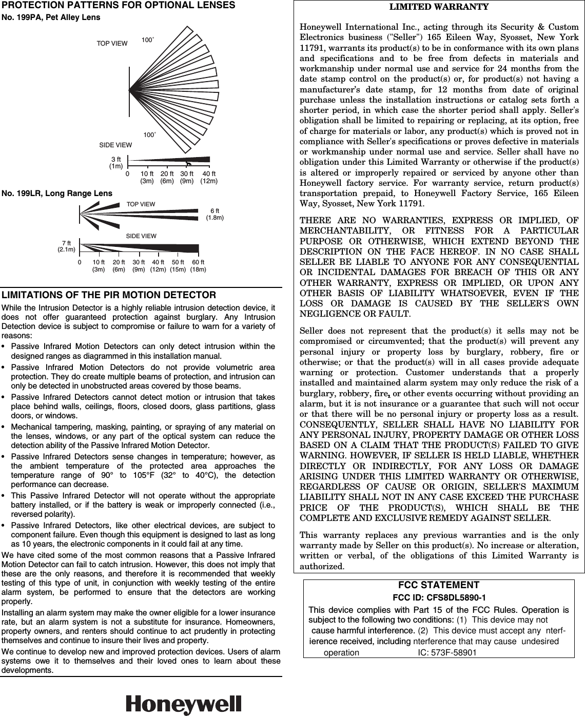
Two optional interchangeable lenses are
available for this detector – the 199PA Pet Alley
lens, and the 199LR Long Range lens (see
PROTECTION PATTERNS FOR OPTIONAL
LENSES on last page).
This document provides installation instructions
for the 5890, but the installer must be familiar
with the Installation Instructions for the QED
5800 Wireless Alarm System with which the
5890 is intended to be used.
FEATURES
•
Wireless operation for fast installation.
•
Dual element pyro-electric sensor provides
positive protection while minimizing false
alarms.
•
Alternate polarity pulse count option offers
greater stability in adverse environments.
•
Provision to turn LED on while walk testing
(LED is turned off after testing).
•
Tampered cover – unit transmits message if
cover is removed.
•
Wall or corner mounting options.
•
Optional Pet Alley and Long Range lenses
available.
SYSTEM DESCRIPTION
Optical System: Uses efficiently designed
Fresnel lenses.
Radio Transmitter: The built-in transmitter
serves only as the communication link to the
alarm system’s Receiver/Control, and can send
alarm, tamper, supervisory, and battery status
m e s s a g e s
t o
t h e
s y s t e m ‘ s
receiver/control. The transmitter is not used for
detection purposes. Each detector has a unique
ID code permanently assigned at the factory.
This ID needs to be «enrolled» by the QED
control system at the time of installation. This
allows each detector used in the system to be
uniquely identified. The QED control must be
programmed to «enroll» the 5890 as an «RF»
type unit (i.e., supervised RF).
To conserve battery life during normal
operation, no more than one transmission
sequence will occur within a 3-minute period.
There is no such time restriction in «test» mode.
Alternate Polarity Pulse Count: Two jumper-
selectable detection response modes are
provided: Instant response (Pulse Count OFF)
and Alternate Polarity Pulse Count (Pulse
Count ON). With Pulse Count OFF, any
detected change in infrared energy will trigger
an immediate alarm signal. This mode is
recommended when the detector is used to
monitor a narrow hallway where coverage is
provided by only a single zone.
Use the Pulse Count ON mode when the
detector is installed in areas where periodic
changes in infrared energy levels are normal
(for example, where forced air heating ducts are
present). In this mode, it requires at least two
detected changes in infrared energy within a
short period before an alarm will be triggered.
Important Note: If the detector is to be used in
the Pulse Count mode, be sure to walk test the
unit in this mode.
SPECIFICATIONS
Coverage:
Standard Lens
Motion
199LR Lens :
199PA Lens :
Pulse Count:
Installer-selectable On/Off link.
Detectable
Walk Rate:
0.5 – 5ft/sec (0.15 – 1.5m/sec).
Mtg. Height:
7ft nominal (2.1m), but may be
mounted at other heights (see
Table 1).
Walk Test
Indicator:
Red LED with Test/Normal
(disable) link.
Batteries:
Two 3-volt Lithium batteries.
Use only Ademco No. 466,
Duracell DL123A, Panasonic
CR123A, Sanyo CR123A, or
Varta CR123A.
0perating
Temperature: 32°F – 122°F (0°C – 50°C)
Operating
Humidity:
Up to 95% RH (max.), non-
condensing.
Dimensions:
2-11/16″W x 5″H x 1-7/8″D
(68mm x 127mm x 48mm).
Q E D
Standard Wide Angle Protection Pattern
BATTERY INSTALLATION
1. Remove front cover by inserting a large
screwdriver blade (or small coin) in groove
between cover and base at the location
shown in Figure 2; rotate blade to override
snap fit, then lift cover off.
:
40 ft x 56 ft (12 m x 17 m).
18 zones (9 long, 5 inter-
mediate, 4 short range).
60 ft x 6 ft (18m x 1.8m).
5 zones (1 long, 2 inter
mediate, 2 short range).
40 ft x 60 ft (12m x 18m)
12 zones.
Figure 1.
1
2. Observing correct polarity, install the two
Lithium batteries (supplied) into the battery
holders, as shown in Figure. 5. Make sure
the batteries are firmly seated.
3. Replace the cover (snap fit).
Battery Caution:
Risk of fire, explosion and burns. Do not recharge,
disassemble, heat above 100°C, or incinerate.
Dispose of used batteries promptly. Keep away
from children.
Programming Note: If the detector’s ID has
not been programmed into the system (i.e.,
this is an initial detector installation), refer to
the PROGRAMMING section below and
perform the ID «enrolling» procedure before
mounting or testing the detector.
PROGRAMMING
The QED control system must «enroll» the
detector’s ID during installation of the system.
The QED control should be programmed to
enroll the 5890 as an «RF» type unit (i.e.,
supervised RF).
To program the detector, place the LED jumper
in the TEST position (see Fig. 5), the Pulse
Count jumper in the OFF position, batteries
installed, and cover on. Temporarily cover the
lens (a cloth will do) to prevent any activation by
the detector.
When prompted for the device’s serial number,
you may either manually enter it or transmit
from the unit (remove the cloth cover and
motion your hand over the lens to activate the
detector, press the tamper switch, etc.). Refer
to the QED control panel installation
instructions for programming details.
Return LED jumper to the NORMAL position
after it is enrolled in the control.
INSTALLATION HINTS
¥
Do not install where the detector is exposed
to direct sunlight or directly above strong
sources of heat.
• Make sure the detection area does not have
obstructions (curtains, screens, large pieces
of furniture, plants, etc.) which may block the
pattern of coverage.
• Avoid locating a unit in areas which contain
objects likely to produce a rapid change in
temperature, such as central heating,
radiators or ducts (or heaters of any kind), air
conditioners, open flame, etc.
• Do not mount on an unstable surface.
INSTALLATION
Radio Transmission Path Check
Verify that a strong transmission path between
the 5890 and the system’s Receiver/Control
exists before permanently mounting the
detector. Do this by performing the Walk Test
(described later) with the detector temporarily
mounted in its proposed location. The 5890 will
transmit when sensing motion (waving arm or
walking into area). Sometimes, moving the
detector only a few inches means the difference
between a strong and weak transmission path.
Experiment until you are satisfied that the
location provides the strongest transmission
path, while still being practical for the protection
pattern desired. This test also verifies that the
detector has been correctly programmed into
the system.
Normal Mounting
Mount the unit to a firm vertical surface (flat on
wall or in corner).
1. Remove front cover.
2. Temporarily loosen (do not remove) the
screw holding the PC board in the detector
base (see Fig. 5 for location of this screw).
«5890» — беспроводной датчик движения
Беспроводной датчик движения «5890» применяется совместно с охранной системой «Vista-501» или «Vista-101» для обнаружения движения нарушителя в охраняемом помещении и передачи сигнала тревоги по радио-каналу на радио-приемник охранной системы. Беспроводной датчик движения «5890» может применяться на различных объектах где нецелесообразна прокладка кабелей, нельзя нарушать дизайн помещения или нужна быстрота установки сигнализации.
Особенности:
возможна установка других линз — линза для защиты от животных и линза-коридор
имеется тампер контакт от взлома датчика
регулировка чувствительности
Модель 5890 устарела, и была снята с производства. Для замены товара, подходящего по характеристикам, обратитесь к менеджеру компании по телефону, или напишите запрос на электронную почту.
Технические характеристики 5890
максимальная зона обнаружения (стандартная линза), м/град: 12×17/90
чувствительный элемент двухплощадный: да
диапазон скорости срабатывания м/с: 0,15-1,5
Номинальная высота установки, м: 2,1
Количество 3- х вольтовых батарей питания (CR123A, DL123A): 2
регулятор чувствительность: есть
Размеры, мм: 68x127x48
N5987-2V1 10/99 Rev. B
$'(0&23,
3$66,9(,1)5$5(‘027,21′(7(&72575$160,77(5
INSTALLATION INSTRUCTIONS
GENERAL INFORMATION
The 5890PI Passive Infrared Motion
Detector/Transmitter is a battery-operated
wireless device intended for use as part of a
5800 series wireless alarm system.
Designed for use in commercial and residential
installations, the 5890PI is a wall-mounted unit
with a standard lens that provides wide-angle
protection up to a range of 35 ft (10.6m). For
best coverage, mount the detector so that the
likely direction of intruder motion is across the
pattern.
When installed per the guidelines, the Split-
Zone Optics technology in the 5890PI provides
reasonable false alarm protection against pets
and other animals up to 40 lbs.
This document provides installation instructions
for the 5890PI, but the installer must be familiar
with the installation instructions for the 5800
Wireless Alarm System with which the 5890PI
is intended to be used.
FEATURES
• Split-Zone Optics provides pet immunity
against animals up to 40 lbs.
• Wireless operation for fast installation.
• Dual-element pyroelectric sensor provides
positive protection while minimizing false
alarms.
• Alternate-polarity pulse count option offers
greater stability in adverse environments.
• Provision to turn LED on while Walk Testing
(LED is turned off after testing).
• Tamper-protected cover; unit transmits
message if cover is removed.
• Wall or corner mounting options.
SYSTEM DESCRIPTION
Optical System
Uses efficiently designed Fresnel lenses with
Split-Zone Optics.
Radio Transmitter
The built-in transmitter serves only as the
communication link to the alarm system’s
Receiver/Control, and can send alarm, tamper,
supervisory, and battery status messages to
the system’s receiver/control. The transmitter is
not used for detection purposes. Each detector
has a unique ID code permanently assigned at
the factory. You must enroll this ID into the
control system at the time of installation. This
allows each detector used in the system to be
uniquely identified. You must program the
control to enroll the 5890PI as an «RF» type unit
(i.e., supervised RF).
To conserve battery life during normal
operation, no more than one transmission
sequence will occur within a 3-minute period.
There is no such time restriction in Test mode.
Alternate-Polarity Pulse Count
Two jumper-selectable detection response
modes are provided:
Instant response
(Pulse
Count OFF) and
Alternate-Polarity Pulse Count
(Pulse Count ON). With Pulse Count OFF, any
detected change in infrared energy triggers an
immediate alarm signal. This mode is
recommended when the detector is used to
monitor a narrow hallway where coverage is
provided by only a single zone. Use the Pulse
Count ON mode when the detector is installed
in areas where periodic changes in infrared
energy levels are normal (for example, where
forced-air heating ducts are present). In this
mode, at least two changes in infrared energy
must be detected within a short period before
an alarm is triggered.
Important Note:
For pet immune
applications, Pulse Count ON is
recommended.
SPECIFICATIONS
Pet Immune
Lens:
35 ft x 45 ft (10.6m x 13.7m).
30 zones (8 long, 7 over 7 inter-
mediate, 4 over 4 short-range).
Pulse Count: Installer-selectable On/Off link.
Detectable
Walk Rate:
0.5–10 ft/Sec (0.15–1.5m/Sec).
Mtg. Height: 7.0 ft recommended (2.1m),
but may be mounted at other
heights (see Table 1).
Walk Test
Indicator:
Red LED with Test/Normal
(disable)
link.
Batteries:
Two 3-volt Lithium batteries.
Use only ADEMCO No. 466,
Duracell DL123A, Panasonic
CR123A, Sanyo CR123A, or
Varta CR123A.
0perating
Temperature: 32°F – 122°F (0°C — 50°C).
Operating
Humidity:
Up to 95% RH (max.), non-
condensing.
Dimensions: 2-11/16″W x 5″H x 1-7/8″D
68mm x 127mm x 48mm.
ALTERNATE
COUNT POLARITY
EACH ZONE CONSISTS
OF 2 FIELDS
0
25′
(7.6m)
25′
(7.6m)
10′
(3m)
20′
(6m)
30′
(9m)
35′
(10.6m)
0
7.5′
(2.3m)
0
10′
(3m)
20′
(6m)
30′
(9m)
35′
(10.6m)
Figure 1. Protection Pattern
BATTERY INSTALLATION
1. Remove front cover by inserting a large
screwdriver blade (or small coin) in groove
between cover and base at the location
shown in Figure 2; rotate blade to override
snap fit, then lift cover off.
2. Observing correct polarity, install the two
Lithium batteries (supplied) into the battery
holders, as shown in Figure 5. Make sure
the batteries are firmly seated.
3. Replace the cover (snap fit).
Battery Caution
Risk of fire, explosion, and burns. Do not
recharge, disassemble, heat above 100°C, or
incinerate. Dispose of used batteries promptly.
Keep away from children.
Programming Note: If you have not
programmed the detector’s ID into the
system (i.e., this is an initial detector
installation), refer to the
PROGRAMMING
section below and perform the ID enrolling
procedure before mounting or testing the
detector.
PROGRAMMING
You must enroll the detector’s ID during
installation of the system. You should
program the 5890PI as an “RF” type unit
(i.e., supervised RF), and the «Loop»
number as «1.»
To program the detector, place the LED jumper
in the TEST position (see Figure 5), the Pulse
Count jumper in the OFF position, batteries
installed and cover on. Temporarily cover the
lens (a cloth will do) to prevent any activation
by the detector.
When prompted for the device’s serial number,
you may either manually enter it or transmit
from the unit (remove the cloth cover and
motion your hand over the lens to activate the
detector, press the tamper switch, etc.).
Refer
to the control panel installation instructions for
programming details.
Return LED jumper to the NORMAL position
after it is enrolled in the control.
INSTALLATION
Installation Hints
•
Do not install where the detector is exposed
to direct sunlight or directly above strong
sources of heat.
•
Make sure the detection area does not have
obstructions (curtains, screens, large pieces
of furniture, plants, etc.) that may block the
pattern of coverage.
•
Avoid locating a unit in areas that contain
objects likely to produce a rapid change in
temperature, such as central heating,
radiators, or ducts (or heaters of any kind),
air conditioners, open flame, etc.
•
Do not mount on an unstable surface.
IMPORTANT: For installation with pets, be
sure to follow the guidelines described in
Table 2.
File Specifications:443/443629-5890pi.pdf file (16 Feb 2023) |
Accompanying Data:
ADEMCO 5890PI Kitchen Appliances, Security Sensors PDF Installation Instructions (Updated: Thursday 16th of February 2023 04:47:42 AM)
Rating: 4.2 (rated by 90 users)
Compatible devices: 650, QUEST 2160, 996EX, 1878, 655, 990, LYNX, 4278EX.
Recommended Documentation:
Manual, Installation Instructions (Text Version):
(Ocr-Read Summary of Contents of some pages of the ADEMCO 5890PI Document (Main Content), UPD: 16 February 2023)
-
ADEMCO 5890PI User Manual
-
ADEMCO 5890PI User Guide
-
ADEMCO 5890PI PDF Manual
-
ADEMCO 5890PI Owner’s Manuals
Recommended: AC Adapter EH-64, CF27F30, infiNET Lamp Dimmer CLF-DIMRFB, FDB1502RG, SPS36123
Links & Tools
-
User’s Guide Model DVA30 AC Voltage and Current Detector Non-Contact Voltage Detection Non-Contact Current Detection Identify “hot” conductors and terminals Trace current carrying conductors behind walls and in conduit Sensitivity adjust to “home” in on conductors Locate hidden wi …
DVA30 4
-
Multi-FrequencyQuad Photobeam DetectorsE-964-Q660Q–660 ft. (200m) outdoors, 1320 ft. (400m) indoorsE-964-Q495Q– 495 ft. (150m) outdoors, 990 ft. (300m) indoorsE-964-Q330Q– 330 ft. (100m) outdoors, 660 ft. (200m) indoorsE-964-Q165Q– 165 ft. ( 50m) outdoors, 330 ft. (100m) indoors®ENFORCERS …
ENFORCER E-964-Q660Q 12
-
Quick Start GuideHome Alarm SystemModel: AL-KIT1-PP2We’d Love to Hear from You!We wanted to personally reach out and thank you for purchasing from our Amazon store. Selling on Amazon is what we do to support our family, and product reviews are the lifeblood of our business. It would mean the world to …
SmartHome AL-KIT1-PP 10
-
ITENSIRENA LED AUTOALIMENTATA DA ESTERNOManuale di installazione, uso e manutenzioneInstallation, operation and maintenance manualSELF POWERED OUTDOOR LED SIREN ART. / ITEM: 1826OBLO/EOBLO’/EMADE IN ITALYLa dichiarazione CE del presente articolo è reperibile sul sito www.lince.net.The CE declaration of this …
OBLO’/E 8
Operating Impressions, Questions and Answers:
Honeywell International Inc. motion detector transmitter N5987V3 Rev A
UserManual.wiki
>
Ademco >
8DL5890 1 User Manual
II with part 15 statment and fcc id number