Airmux-200 . Радиомультиплексор . Оптоволоконные модемы DSL и радиомультиплексор . Оборудование RAD . Сетевое и телекоммуникационное оборудование
Airmux-200 – высокопроизводительный, недорогой мультиплексор операторского класса, предназначенный для соединения сетей E1/T1 и Ethernet по радиоканалам по схеме «точка-точка». Устройство соответствует требованиям FCC, CAN/CSA и ETSI для работы в нелицензируемых частотных диапазонах. Airmux -200 может использоваться в диапазонах 2.4 ГГц, 4.9 ГГц и 5.x ГГц, а также в диапазоне 2.5 ГГц BRS. Использование радиоканала позволяет корпоративным пользователям сэкономить на цене выделенных линий, а поставщикам услуг — не прокладывать оптоволоконные кабели. Таким образом, обеспечивается быстрое развертывание сетевой инфраструктуры E1/T1 и Ethernet при низких затратах.
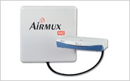
Устройство состоит из наружного и внутреннего блоков, соединенных Ethernet кабелем Cat- 5e для наружного применения, позволяющим размещать блоки на расстоянии до 100 метров друг от друга. Наружное устройство поставляется со встроенной антенной или с коннектором для внешней антенны.
Airmux -200 мультиплексирует до четырех неструктурированных каналов E1 или T1 и трафик портов Ethernet для передачи по радиоканалу с полосой пропускания в 48 Мбит/с. Это соответствует полезной нагрузке 18 Мбит/с по полному дуплексу. Максимальная дальность работы устройства составляет 80 км, а максимальная производительность зависит от расстояния и от разрешенного диапазона частот.
Встроенный мост 10/100BaseT Ethernet прозрачным образом пересылает фреймы и запоминает до 2000 MAC адресов. Tочное восстановление синхронизации E1/T1, низкая двусторонняя задержка и высокая готовность канала превращают Airmux -200 в систему передачи операторского класса.
В Airmux -200 реализованы механизмы защиты радиоканала от несанкционированного доступа. Алгоритм шифрования AES и динамическая смена ключей исключает возможность подслушивания. Дополненные кодированной отметкой времени (CCM), эти механизмы предотвращают вмешательство подставного передатчика в работу канала. Система сетевого управления и сами устройства защищены паролями и применением схемы “запрос-ответ”.
Управление каналом в устройстве Airmux -200 может осуществляться с помощью приложения на основе Windows, поставляемого вместе с устройством.
Eсли необходимо управлять большим числом каналов с центральной платформы, можно заказать систему управления отказами RADview на базе SNMP. Все параметры конфигурации настраиваются по соединениям, что упрощает инсталляцию и обслуживание.
Airmux-200 — отличное решение для соединения удаленных корпоративных офисов, базовых станций сотовых сетей, предоставления услуг широкополосного доступа и подключения хот-спотов.
Airmux-200 также работает в режиме Power over Ethernet для услуг Ethernet и в конфигурации «многоточка-точка» с совместным размещением нескольких устройств.
Table of Contents for Airmux Airmux-200:
-
Installation and Operation Manual Chapter 5 Monitoring and Diagnostics Airmux-200 Ver. 1.9.3 Collecting Unified Performance Information 5-11 ³ To reset the monitoring and alarm preferences to defaults: 1. From the Tools menu, choose Preferences. The Preferences dialog box appears. Figure 5-6. Preferences Dialog Box, Advanced Tab 2. Click the Advanced tab (see Figure 5-6 ). 3. Click the Restore Defaults button. 4. Confi
-
Chapter 6 Software Upgrade Installation and Operation Manual 6-2 Airmux-200 Ver. 1.9.3 Figure 6-2. Adding Sites to Upgrade 3. Select Add Single Site to add one site only. The Add Site for Software Upgrade dialog box is displayed. Figure 6-3. Add Site for Software Upgrade Dialog Box 4. Enter the IP address of the site, the community strings (default: public and netman, respectively) and then click OK. The site appears in the Software Upgrade list box. For example if we add the site at IP address 192.168.2.101, the SWU main window looks like
-
Appendix J FCC/IC DFS Installation Procedure Installation and Operation Manual J-6 Configuring FCC/IC 5.4/5.3 GHz Link Airmux-200 Ver. 1.9.3
-
Installation and Operation Manual Chapter 2 Installation and Setup Airmux-200 Ver. 1.9.3 Installing the Link 2-25 Figure 2-18. Installation Wizard, System Dialog Box, Fields are Filled Out 6. Click Next. The default link with a rate of 6.5 Mbps is evaluated. The Channel Setting dialog box appears. This dialog box may be different according to the version that you have purchased. Changing the Link Password The default password is wireless-bridge . Optionally, you can change the link password as explained here. ³
-
Installation and Operation Manual Appendix F Preloading IP Address and Changing Default Band Airmux-200 Ver. 1.9.3 Changing the Factory-Default Band F-7 Figure F-8. Opening Airmux Manager Window prior to Band Change If you are changing the band on an installed link, change the “over the air” site (site B) first. Otherwise you will lock yourself out of the link. 7. Select Tools > Change Band.
-
Chapter 4 Configuration Installation and Operation Manual 4-34 Configuring the Sites Airmux-200 Ver. 1.9.3 4. Select egress mode for LAN 1, LAN 2 and SFP ports: Transparent Untag all Untag selected VLAN IDs Provider tagging Provider tagging without filter Filtered VLAN IDs See Port Functionality section above for description of the egress modes. The first two choices, Transparent and Untag all require no further action. Untag selected VIDs causes the eight VLAN ID fields to become available: Figure 4-32
-
Installation and Operation Manual Appendix G Hub Site Synchronization Airmux-200 Ver. 1.9.3 Hardware Installation G-3 G.1 Hardware Installation A single HSS unit supports up to ten collocated ODUs. In addition to each unit being connected to its IDU or PoE device, the collocated unit has an additional cable that is connected to the HSS unit. The HSS unit is a compact, weatherproof (IP67) connector box that is installed on the same mast as the ODUs. All collocated units connect to this box using CAT-5e cable. Cables in prepare
-
Chapter 7 Application Tutorial Installation and Operation Manual 7-16 Point-to-Point Application Airmux-200 Ver. 1.9.3 2. Select Air Interface and set the transmit power to 9 dBm. Figure 7-19. Air Interface Configuration 3. Select Management and set the IP addresses as follows: HQ ODU –192.168.0.3 Remote branch ODU – 192.168.0.4 PC (trap destination) – 192.168.0.2
-
Appendix J FCC/IC DFS Installation Procedure Installation and Operation Manual J-2 Activating FCC/IC 5.4/5.3 GHz Link Airmux-200 Ver. 1.9.3 Figure J-1. Activating an ODU, Inactive Manager Window 4. Select Site:Location > Air Interface for the logged in site. The Air Interface dialog box opens: Figure J-2. Air Interface Dialog Box 5. Enter the Link ID and note it for use with the second site of the link. 6. Check the Master rad
-
Chapter 3 Operation Installation and Operation Manual 3-8 Configuration and Management Alternatives Airmux-200 Ver. 1.9.3 Red is an inactive link Magenta shows an authentication or compatibility problem Brown shows severe compatibility problem Events Log – stores alarms generated by local and remote units. • Status Bar – displays the following icons: Connect
-
Appendix I MIB Reference Installation and Operation Manual I-16 MIB Parameters Airmux-200 Ver. 1.9.3 Name OID Type Access Description radwllMilOduAirSpectrumAnalysisO perState 1.3.6.1.4.1.4458.1000.1.5.56.1 Integer RW Spectrum Analysis operation state. The configurable values are Spectrum Analysis Stop Start and Restart. Not Supported value indicates that the feature is not supported on the device. Not Supported is not a configurable state. radwllMilOduAirRxPowerAntennaA
Questions, Opinions and Exploitation Impressions:
You can ask a question, express your opinion or share our experience of Airmux Airmux-200 device using right now.
-
Page 1
Airmux-200 Wireless Broadband Multiplexer Version 1.900 The Access Company… -
Page 3: Installation And Operation Manual
This Agreement is effective upon your opening of the Airmux-200 package and shall continue until terminated. RAD may terminate this Agreement upon the breach by you of any term hereof. Upon such termination by RAD, you agree to return to RAD the Airmux-200 and all copies and portions thereof.
-
Page 4: Limited Warranty
Agreement and the Airmux-200 shall not exceed the sum paid to RAD for the purchase of the Airmux-200. In no event shall RAD be liable for any indirect, incidental, consequential, special, or exemplary damages or lost profits, even if RAD has been advised of the possibility of such damages.
-
Page 5: Safety Symbols
General Safety Instructions The following instructions serve as a general guide for the safe installation and operation of telecommunications products. Additional instructions, if applicable, are included inside the manual. Safety Symbols This symbol may appear on the equipment or in the text. It indicates potential safety hazards regarding product operation or maintenance to operator or service personnel.
-
Page 6: General Safety Practices
Handling Energized Products General Safety Practices Do not touch or tamper with the power supply when the power cord is connected. Line voltages may be present inside certain products even when the power switch (if installed) is in the OFF position or a fuse is blown.
-
Page 7
The maximum permissible current capability of the branch distribution circuit that supplies power to the product is 16A (20A for USA and Canada). The circuit breaker in the building installation should have high breaking capacity and must operate at short-circuit current exceeding 35A (40A for USA and Canada). -
Page 8
When using shielded or coaxial cables, verify that there is a good ground connection at both ends. The grounding and bonding of the ground connections should comply with the local codes. The telecommunication wiring in the building may be damaged or present a fire hazard in case of contact between exposed external wires and the AC power lines. -
Page 9
FCC-15 User Information This equipment has been tested and found to comply with the limits of the Class A digital device, pursuant to Part 15 of the FCC rules. These limits are designed to provide reasonable protection against harmful interference when the equipment is operated in a commercial environment. This equipment generates, uses and can radiate radio frequency energy and, if not installed and used in accordance with the Installation and Operation manual, may cause harmful interference to the radio communications. -
Page 10
Mise au rebut du produit Afin de faciliter la réutilisation, le recyclage ainsi que d’autres formes de récupération d’équipement mis au rebut dans le cadre de la protection de l’environnement, il est demandé au propriétaire de ce produit RAD de ne pas mettre ce dernier au rebut en tant que déchet municipal non trié, une fois que le produit est arrivé… -
Page 11
Certains produits peuvent être équipés d’une diode laser. Dans de tels cas, une étiquette indiquant la classe laser ainsi que d’autres avertissements, le cas échéant, sera jointe près du transmetteur optique. Le symbole d’avertissement laser peut aussi être joint. Avertissement Veuillez observer les précautions suivantes : •… -
Page 12
Connexion au courant du secteur Assurez-vous que l’installation électrique est conforme à la réglementation locale. Branchez toujours la fiche de secteur à une prise murale équipée d’une borne protectrice de mise à la terre. La capacité maximale permissible en courant du circuit de distribution de la connexion alimentant le produit est de 16A (20A aux Etats-Unis et Canada). -
Page 13
The following AirMux-200 systems comply with European regulations: • Airmux-200/F24E/ in the frequency range 2400-2485 MHz (RLAN). No restrictions on use. • Airmux-200/F54E/ in the frequency range 5470-5725 MHz (HIPERLAN). The following… -
Page 14: Declaration Of Conformity
24 Raoul Wallenberg St., Tel Aviv 69719, Israel declares that the product: Product Name: Airmux-200/F24E in the frequency range 2.400-2.4835 GHz Conforms to the following standard(s) or other normative document(s): Radio: EN 300 328 V1.4.1 Electromagnetic compatibility and Radio spectrum Matters (ERM);…
-
Page 15
24 Raoul Wallenberg St. Tel Aviv 69719, Israel declares that the product: Product Name: Airmux-200/F54E in the frequency range 5.470-5.725 GHz Conforms to the following standard(s) or other normative document(s): Radio: EN 301 893 V1.2.3 Broadband radio Access Networks (BRAN); 5 GHz high performance RLAN;… -
Page 17: Equipment Required
Quick Start Guide Installation of Airmux-200 should be carried out only by a qualified technician. If you are familiar with Airmux-200, use this guide to prepare the units for operation. If you are not familiar with Airmux-200, please read the Installation and Operation Manual carefully.
-
Page 18
Quick Start Guide Installation and Operation Manual Installing the Airmux-200 Units To install the ODU: 1. At site A, route the ODU cable from the ODU location (on the roof) to the IDU location (inside the building). The maximum length is 100m. -
Page 19
A ODU position is learned by the site B ODU. 7. Turn the site B ODU slowly back towards the site A direction, listening to the beep sequence until optimal alignment is achieved. Airmux-200 Ver. 1.900 Installing the Airmux-200 Units… -
Page 20
After selection of the radio channel and the link rate (as determined in the Link Budget Calculator utility), verify that the link quality bar in the Airmux-200 manager is within the green range for TDM service and within the yellow range for Ethernet service. -
Page 21: Connecting The Power
4. Wait for approximately one minute, then repeat for Site B. Connecting Power to an IDU-E AC power to the Airmux-200 should be supplied via a 1.5m (5 ft) standard power cable terminated by a standard 3-prong socket. A cable is provided with the unit.
-
Page 22
For O-PoE only UL Listed parts and components are used for installation. Use UL Caution listed devices having an environmental rating equal to or better than the enclosure rating to close all unfilled openings. Connecting the User Equipment Airmux-200 Ver. 1.900… -
Page 23: Table Of Contents
Installation Sequence ……………….. Surveying the Site …………………. Planning the Link Site ………………… Site Survey …………………. Stage 1 (Preliminary Survey) ……………. Stage 2 (Physical Survey) ………………. Stage 3 (RF Survey) ……………….. Airmux-200 Ver. 1.900…
-
Page 24
Mounting the Lightning Protection Devices …………… 2-11 2.10 Connecting the ODU to the IDU …………….2-12 2.11 Installing the Airmux-200 Management Software …………2-13 2.12 Connecting to Power ………………..2-14 Connecting Power to an IDU …………….. -
Page 25
Managing Configuration Files …………….4-27 Reinstalling the Link ………………4-28 Configuring Link Security ……………… 4-28 Resetting Airmux-200 ………………4-30 Chapter 5. Monitoring and Diagnostics Monitoring Performance ………………… Viewing Performance Reports …………….. … -
Page 26
Equipment List …………………. Calculating Expected Link Performance ………….. Surveying the Sites ……………….. Installing the Airmux-200 Management Software…………. Installing Airmux-200s ………………… Aligning the Antennas ………………… Configuring the Link Using the Link Installation Wizard ………. -
Page 27: Product Options
Several special systems are also available; • AIRMUX-200-AIND, All Indoor unit, F58/FCC with 4T1 support. AIRMUX-200-AIND integrates the ODU and the IDU-E into a single 19″ IDU-E box. • AIRMUX-200-L, Ethernet only units powered over the Ethernet via PoE unit.
-
Page 28: Applications
Chapter 1 Introduction Installation and Operation Manual Applications Figure 1-1 illustrates a typical point-to-point application of two Airmux-200 units. Figure 1-1. Typical Point-to-Point Application Point-to-point application with automatic radio link backup is illustrated below. Figure 1-2. Automatic Radio Link Backup Figure 1-3 illustrates Airmux-200 units in video surveillance applications.
-
Page 29: Features
Features Wireless Link Airmux-200 delivers up to 48 Mbps air rate for Ethernet and E1/T1 traffic. The system supports a variety of spectrum bands and can be configured to operate in any channel in the band with a carrier step resolution of 5 MHz and channel bandwidth of 5, 10, or 20 MHz.
-
Page 30: Tdm Interface
1+1 Link Redundancy The 1+1 link redundancy mechanism (Monitored Hot Standby, or MHS) supports up to four E1 services for Airmux-200 or up to 16 E1 services for Airmux-400 and is designed to provide high reliability high-capacity point-to-point links. It is: •…
-
Page 31: Automatic Channel Select
Some versions of Airmux-200 have the Automatic Channel Select feature, which operates via a Dynamic Frequency Selection (DFS mechanism). This enables coexistence with any radar system that may be active in the area. Airmux-200 performs channel monitoring and selects the channel with the lowest interference for the transmission.
-
Page 32: Hub Site Synchronization
IDU-R units have a secondary E1 input which may be connected to external equipment other than the ODU. This provides backup in the event of failure of either the air interface link of the Airmux-200, or the secondary E1 link. Overview…
-
Page 33: Vlan Management
VLAN management. Physical Description An Airmux-200 system may consist of an Outdoor Unit (ODU) and an Indoor Unit, which may be an IDU or an IDU-E; an All Indoor Unit, AIND; or an outdoor PoE, O-PoE, housed in a weather proof enclosure.
-
Page 34: Idu-E
The user configures which of the two links is the main link and which is the backup link. IDU-R operates with all Airmux-200 outdoor units. ODU includes an RJ-45 connector, which receives -48 VDC, and Ethernet traffic from the IDU.
-
Page 35: Poe-8
Chapter 1 Introduction PoE-8 Airmux-200 PoE-8 is an IDU for collocated Ethernet applications. It features 8 Ethernet ports, 8 decoupled ports of ODU, 2 outputs of dry contact alarms, and receives power by AC, DC, or both as either AC input or DC input – 20V — 60V.
-
Page 36: Functional Description
It converts 100–240 VAC to -48 VDC, and sends it on to the ODU. The IDU does not store any configuration data. Therefore, there is no need for additional configuration of the Airmux-200 system when replacing an IDU. • IDU-R: The unit monitors the status of leased lines, and in the event of a connection failure automatically switches to the radio link.
-
Page 37: Technical Specifications
5.740–5.940 5.9, non-regulated 5.805–6.020 6.0, non-regulated Antennas Table 1-2 LAN Interface Up to 2 × 10/100BaseT, auto-sensing Framing/Coding IEEE 802.3/U Bridging Self-learning, up to 2048 MAC addresses Line Impedance 100Ω (10/100BaseT) VLAN Support Transparent Airmux-200 Ver. 1.900 Technical Specifications 1-11…
-
Page 38
ODU plus IDU-E – 14W max O-PoE plus ODU – 25W max PoE-8 plus 8 ODU units – 60W max Connector IDU 2-pin IDU-E AC – 3-pin IEC connector DC – 3-pin terminal block 1-12 Technical Specifications Airmux-200 Ver. 1.900… -
Page 39
32.5 Dia 900 Dia 35.4 N-type 4.9 GHz External Flat panel 305×305×58 12×12×2.3 N-type External Dish Dia 600 Dia 23.6 11.0 N-type 2.4 GHz Integrated Flat panel 305×305×58 12×12×2.3 External Grid 600×997×380 23.5×39.2×15 N-type Airmux-200 Ver. 1.900 Technical Specifications 1-13… -
Page 40
Chapter 1 Introduction Installation and Operation Manual 1-14 Technical Specifications Airmux-200 Ver. 1.900… -
Page 41: Installation And Setup
Do not activate indoors an ODU with an integrated or external antenna. To test an active radio link inside the building, use an attenuated RF cable (at least 40 dB) for the ODU connection. Warning Airmux-200 Ver. 1.900 Safety Practices…
-
Page 42: Grounding
It also lays down the size of grounding conductors and connection requirements for grounding electrodes. The Airmux-200 ODU must be grounded to a protective earth as described in Appendix D and in accordance with the local electrical regulations.
-
Page 43: Grounding For Indoor/Outdoor Units
Grounding for Indoor/Outdoor Units ODU (Outdoor Unit) Grounding Airmux-200 uses a shielded CAT-5 cable to interconnect the Outdoor (ODU) and Indoor (IDU) units. However, this shielding does not provide a good lightning discharge path, since it cannot tolerate the high lightning current surges.
-
Page 44: Site Requirements And Prerequisites
Q3KAMWL1490H 5100A-AMWL1490H Q3KAMWL1490H 5100A-AMWL1490H 18.5 5.3/5.4 Q3KAMWL1540C 5100A-AMWL1540C Table 2-2. Safety Distances for Airmux-200 ETSI Products Frequency Band Antenna Gain Min. Safety Distance [GHz] [dBi] [cm] Site Requirements and Prerequisites For the IDU units, allow at least 90 cm (36 in) of frontal clearance for operating and maintenance.
-
Page 45
O-PoE package contains: O-PoE Mast/wall mounting kit plus mounting instructions Additional Equipment Required The following is a list of the equipment required for installing the Airmux-200 hardware: • Two RJ-45 connectors and an RJ-45 crimp tool (if pre-assembled ODU/IDU cable is not used) •… -
Page 46
Chapter 2 Installation and Setup Installation and Operation Manual Installation Sequence Install the Airmux-200 system according to the following the steps: 1. Survey the site. 2. Mount ODUs at both sites of the link. 3. Mount external antennas (if necessary). -
Page 47: Site Survey
Installation and Operation Manual Chapter 2 Installation and Setup Surveying the Site This section explains how to survey the site intended for Airmux-200 installation. Planning the Link Site Link site planning consists of a set of surveys, which must be carried out before any equipment is brought to the site.
-
Page 48: Stage 1 (Preliminary Survey)
7. If the site chosen does not meet requirements, consider alternative sites. 8. Use the Link Budget Calculator (on the CD supplied with Airmux-200 or using the Airmux Manager) to determine the expected performance. Stage 2 (Physical Survey)
-
Page 49: Stage 3 (Rf Survey)
Allow 2–4 hours duration for a good RF survey. Note It is possible to install the Airmux-200 link and use the Airmux Manager to find a clear channel. Each frequency channel can be evaluated in turn. Achievement of a clear channel is indicated by the Quality bar on the Channel Setting window becoming green.
-
Page 50: Mounting The Odu Or O-Poe
Installation and Operation Manual Mounting the ODU or O-PoE The ODU is the transmitting and receiving element of the Airmux-200 system. The ODU or O-PoE can be mounted on a mast or a wall. In both installations, the Appendix B supplied mounting kit is used to secure the ODU.
-
Page 51: Mounting The Lightning Protection Devices
Mounting the Lightning Protection Devices The use of lightning protection is dependent on regulatory and end user requirements. The Airmux-200 ODU is designed with surge limiting circuits to minimize the risk of damage due to lightning strikes. RAD recommends the use of additional surge arrestor devices to protect the equipment from nearby lightning strikes.
-
Page 52: 2.10 Connecting The Odu To The Idu
The figures below illustrate typical IDU panels. There may be differences in panels depending on the hardware ordered. DC IN 48-60V — 1A TRUNK 1 TRUNK 2 Figure 2-3. Typical IDU Rear Panel Figure 2-4. Typical IDU-E Front Panels 2-12 Connecting the ODU to the IDU Airmux-200 Ver. 1.900…
-
Page 53: 2.11 Installing The Airmux-200 Management Software
Panels may be fitted with different connector combinations than shown, depending on the model ordered. 2.11 Installing the Airmux-200 Management Software The Airmux-200 management application is distributed on CD-ROM as an executable file. The application has the following PC requirements: •…
-
Page 54: 2.12 Connecting To Power
Intentional interruption is prohibited. Connecting Power to an IDU Power is supplied to the Airmux-200 IDU via an external AC/DC converter, which receives power from a 100–240 VAC source and converts it to -48 VDC. To connect power to the IDU: 1.
-
Page 55: Connecting Power To An O-Poe
ODUs. The beeper facility is not suitable for aligning the All Indoor Units (AIND). Appendix E To align an AIND system, see To speed up the installation time, alignment of Airmux-200 link can be performed by two teams simultaneously, at site A and at site B. To align the antennas via ODU beeper: 1.
-
Page 56: 2.14 Starting The Manager Software
3. Check that you have connectivity to the ODU. You can do this by opening up a command line session (Start>Run and then type, cmd). At the command prompt, type: ping 10.0.0.120 You should receive a reply from Airmux-200. 2-16 Starting the Manager Software…
-
Page 57
Ethernet connection and that both the IDU and ODU are switched on and then try again. 4. Dismiss the command line session. 5. Double-click the Airmux Manager icon on the desktop, or click Start > Programs > Airmux Manager > Airmux Manager. The Login dialog box appears. -
Page 58
Community in the Read-Only or Read-Write boxes. If you are a user with read-only permission, click the Read Only Mode check box. Note Airmux-200 is protected with Community passwords. A user may be defined with read-only permission or with read-write permission (see Chapter 4 for more details). -
Page 59: Login Errors
A red Inactive Link box appears in the center of the Manager screen. Activation is performed later. 8. Click OK to log in. Figure 2-14 The Airmux Manager main window is displayed (see Login Errors This section describes problems that may occur during login. Unsupported Device…
-
Page 60: Incorrect Password
In both of the above situations, you will see a warning graphic alongside the IP Address field. Incorrect Password If you type an incorrect password in the Login screen, a warning graphic displayed alongside the password field. Figure 2-14. Airmux-200 Manager Main Screen 2-20 Starting the Manager Software Airmux-200 Ver. 1.900…
-
Page 61: 2.15 Selecting The Management Connection Method
To install the link: 1. Verify that the management station is properly connected to the same LAN as the IDU, and the Airmux-200 Manager application is running. 2. With BRS systems you need to activate the link at both sites, see Appendix H for method.
-
Page 62
5. Optionally enter a new link password (see details.) The Change Link Password dialog box opens. Note Use the Hide Characters check box for maximum security. Figure 2-17. Change Link Password Dialog Box 2-22 Installing the Link Airmux-200 Ver. 1.900… -
Page 63
Both sides of a link must have the same SSID number for data transmission to Note take place. 13. Enter a Link Name for the link identification. 14. Enter a name for site 1. 15. Enter a name for site 2. Airmux-200 Ver. 1.900 Installing the Link 2-23… -
Page 64: Selecting Channels
This dialog box may be different according to the version that you have purchased. Selecting Channels Airmux-200 has a feature called Automatic Channel Select, which allows you to define several alternative frequency channels if interference is detected on the channel in use.
-
Page 65: Airmux-200 5.4 Ghz Etsi Version
This feature is termed Dynamic Frequency Selection (DFS). According to the standard, a channel with active radar is prohibited from use for 30 minutes. Before any transmission, Airmux-200 probes a channel for radar signals for a period of 60 seconds.
-
Page 66
Figure 2-20. Channel Select Dialog Box (DFS, ETSI Requirement) sign on the configuration Wizard and Status bar indicates that the radar detection is on. To configure Airmux-200 5.4 GHz ETSI version: 1. Select the main frequency from the Operating Channel menu. 2. Select the Bandwidth required. -
Page 67: Airmux-200 Brs Version
The Evaluating Rate box appears. The optimum rate for the link is selected. The Service Parameters dialog box opens. Airmux-200 BRS Version Both sites in a BRS Link must be configured identically. Note Any changes to the frequency settings cause the link to re-synchronize. A short loss of service will occur during re-synchronization.
-
Page 68: Configuring Hub Site Synchronization
If you do not require HSS, click Next. Selecting the Service Parameters Airmux-200 supports Ethernet and TDM services, which are configured via the Services dialog box. Note Airmux-200-L versions are Ethernet Only.
-
Page 69
3. Select active TDM ports: Use Select spin box to choose consecutive service ports Click Select Maximum to choose all TDM port available for current air interface capacity Click individual ports to choose them. Airmux-200 Ver. 1.900 Installing the Link 2-29… -
Page 70
Figure 2-25. Link Installation Wizard, TDM Services Dialog Box, Seven TDM Ports are Selected 4. Click OK. The Services dialog box is updated to reflect your choice. Figure 2-26. Installation Wizard, Services Dialog Box with Services Added 2-30 Installing the Link Airmux-200 Ver. 1.900… -
Page 71
The optimum transmission rate for the selected services is evaluated. Table 2-4 shows the rates used by Airmux-200. Airmux-200-L versions do not have TDM services, they operate at a default rate Note of 2 Mbps. Table 2-4. Rates Per Bandwidth… -
Page 72: Configuring The Jitter Buffer
Use extra caution when decreasing the jitter buffer value, since the interference may affect service quality. In cases of asymmetric interference, the jitter buffer can be set to different values per site. In such cases the latency will also be asymmetric. 2-32 Installing the Link Airmux-200 Ver. 1.900…
-
Page 73: Configuring Hot Standby
If TDM services are selected then the TDM parameters dialog box appears. (TDM is not relevant in Airmux-200-L versions.) Airmux-200 uses plesiosynchronous timing. Data and clocking is transferred over the air, locked to the Master clock. A port used as a Master clock source can be selected by the user or automatically.
-
Page 74
This dialog box is available only with IDU units, it is activated after TDM service was chosen in the previous Service dialog box. In Ethernet only services, the TDM dialog box does not appear. 2-34 Installing the Link Airmux-200 Ver. 1.900… -
Page 75: Setting The T1 Line Code
The T1 line code can be set as B8Zs or AMI in the TDM Parameters dialog box. The default is B8ZS. Figure 2-31. TDM Parameters Dialog Box, T1 Interface To change the T1 line code • In the TDM Parameters dialog box, set the line code to B8ZS or AMI. Airmux-200 Ver. 1.900 Installing the Link 2-35…
-
Page 76: Configuring The Tdm Backup
Installation and Operation Manual Configuring the TDM Backup IDU-R units have two E1 trunk lines, one for Airmux-200 air interface via the ODU, and the second external equipment such as a PBX. The TDM backup screen is displayed in IDU-R systems only.
-
Page 77
Installation and Operation Manual Chapter 2 Installation and Setup 3. Click Next. The Installation Wizard, Finish Screen appears: Figure 2-34. Installation Wizard, Finish Screen 4. Click Done to complete the installation wizard. Airmux-200 Ver. 1.900 Installing the Link 2-37… -
Page 78: 2.17 Connecting To E1/T1 Equipment
5. Verify that the Radio Signal Strength (RSS) is according to expected results as determined by the Link Budget Calculator. 2.17 Connecting to E1/T1 Equipment E1/T1 devices are connected to Airmux-200 via balanced RJ-45 ports designated TRUNK. There may be multiple trunk ports available depending on unit ordered. Appendix A Refer to for the E1/T1 connector pinout.
-
Page 79: 2.18 Connecting To Ethernet Equipment
Chapter 2 Installation and Setup 2.18 Connecting to Ethernet Equipment Airmux-200 is connected to the Ethernet equipment via the 8-pin RJ-45 electrical port or SFP designated LAN. There may be multiple LAN ports available for connecting to different LANs depending on the IDU unit ordered.
-
Page 80
Chapter 2 Installation and Setup Installation and Operation Manual 2-40 Connecting to Ethernet Equipment Airmux-200 Ver. 1.900… -
Page 81: Chapter 3. Operation
The PWR indicator lights up (IDU only) and remains lit as long as the IDU is receiving power. Airmux-200 requires no operator attention once installed, with the exception of occasional monitoring of front panel indicators and statistics data. Intervention is only required when Airmux-200 must be configured to its operational requirements, or diagnostic tests are performed.
-
Page 82: Wan/Lan Indicators
Chapter 3 Operation Installation and Operation Manual Figure 3-1. IDU Front Panel Figure 3-2. Airmux-200-AIND All Indoor Radio Unit Table 3-1. Front Panel LEDs Name Color Description Green ON –Power supply is ON (IDU only) Green ON – IDU operational Orange ON –…
-
Page 83: Normal Indications
Green LED Red LED Loopback Blinking Normal Indications After turning on Airmux-200, the PWR LED in the IDU front panel lights to indicate Table 3-4 that Airmux-200 is on. shows the correct status of the indicators at power-up. Table 3-4. Airmux-200 Indicators at Startup…
-
Page 84: Default Settings
• GUI-based management utility • Telnet. Most of the Airmux-200 management and operation parameters are set using link configuration wizard. If necessary, the local and remote unit parameters can be reconfigured via the Airmux-200 management utility. Configuration and Management Alternatives…
-
Page 85: Working With The Management Utility
Figure 3-3 appear in the event log (see Figure 3-3. Main Screen, Wireless Link is Active The Airmux Manager main screen consists of the following elements: • Toolbar – includes buttons serving for: Changing configuration parameters of operating wireless link; assigning…
-
Page 86
Tools – set performance monitoring, event log handling, change password and preferences Maintenance – Loopbacks, system reset Help – Airmux Manger help • Link details pane – summarizes information on the radio frequency, IP bandwidth, type of TDM service, number of assigned E1 or T1 timeslots. -
Page 87
For each Trunk the line status and Error block count is displayed. It is zeroed by the Clear Counters button in the tool bar. The line status is color coded and may be one of: Green – Normal Airmux-200 Ver. 1.900 Configuration and Management Alternatives… -
Page 88
Link Password Validation failed. The link is encrypted with default keys. Service and configuration is unavailable. Need to change the link password in either site No Encryption – An older release is used, no encryption is available. Ethernet bandwidth indication Configuration and Management Alternatives Airmux-200 Ver. 1.900… -
Page 89: Over The Air Connection Indication
3. Continue through the configuration wizard and define the Link name and ID, Channel, Rate and Services. 4. Once you finish changing configuration parameters, click Finish. The system takes a few seconds to activate the link with the new configuration. Airmux-200 Ver. 1.900 Configuration and Management Alternatives…
-
Page 90: Verifying The Application Software Version
Read/write allows using display commands netman (default value is Table 3-6 lists the Telnet commands supported by Airmux-200. Table 3-6. Telnet Commands Command Description display inventory Displays ODU product name, name, location, hardware and software revisions, uptime, MAC address, IDU product name,…
-
Page 91
Reset both the IDU and the ODU. The user shall be prompt that the command will reset the device and that he/she has to restart the Telnet session. help Displays the available commands Figure 3-6 shows the available Telnet commands via the Help command. Airmux-200 Ver. 1.900 Working with Telnet 3-11… -
Page 92: Turning Off The Unit
Command «help» finished OK. Figure 3-6. Telnet Management Screen Turning Off the Unit To turn off Airmux-200: 1. Exit the management application. 2. Remove the Airmux-200 power cord from the mains. 3-12 Turning Off the Unit Airmux-200 Ver. 1.900…
-
Page 93: Chapter 4. Configuration
Chapter 4 Configuration This chapter describes configuration procedures, which are performed after the physical installation of the local and remote Airmux-200 units and the Installation Link wizard has been performed. The following parameters are configured via the Configuration Wizard: •…
-
Page 94
Chapter 4 Configuration Installation and Operation Manual Figure 4-1 2. The Link Configuration wizard opens ( Figure 4-1. Configuration Link Wizard 3. Click Next. Figure 4-2 The Link Configuration dialog box appears (see Configuring the Link Airmux-200 Ver. 1.900… -
Page 95: Selecting Channels
Selecting Channels The user is required to define the operating frequency channel. Newer versions of Airmux-200 have a feature called Automatic Channel Select. This allows you to define several allowable frequency channels that Airmux-200 can change to in event that the link quality deteriorates.
-
Page 96
It tries to select the optimal pure channel. If another channel is required, the operating channel that the ODU finds most pure must be removed from the available channel list. 6. Click Next. The Services dialog box appears. Configuring the Link Airmux-200 Ver. 1.900… -
Page 97: Airmux-200 5.4 Ghz Etsi Version
Frequency Selection (DFS). According to the standard, a channel with active Radar is prohibited from use for 30 minutes. Before any transmission, Airmux-200 probes a channel for Radar signals for a period of 60 seconds. In the 5.4 GHz ETSI version, the Automatic Channel Selection is selected by default and a minimum of two channels must be defined as available.
-
Page 98: Airmux-200 Brs Version
The quality bar shows the adjustment until the system finds the best quality link. 5. Click Next. The Service Parameters dialog box appears. Airmux-200 BRS Version Note Both sites in a BRS Link must be configured identically. Any changes to the frequency settings cause the link to re-synchronize. A short loss of service will occur during re-synchronization.
-
Page 99: Configuring Service Parameters
Note Airmux-200-L versions are Ethernet Only. In the Service Parameters dialog box select if Airmux-200 is to provide E1/T1, (x1 or x2 for IDU, or x4 for IDU-E). Define the required transmission rate. To configure E1/T1 and Ethernet services: 1.
-
Page 100
Chapter 4 Configuration Installation and Operation Manual The default rate is Adaptive. Airmux-200-L versions only operate in adaptive mode. Adaptive Modulation — The system changes modulation automatically depending on channel characteristics in order to guarantee continuation of service. The adaptive modulation enables the user to maximize Ethernet throughput without degradation of the TDM service quality. -
Page 101: Configuring Tdm Services
Hot standby configuration is detailed in Configuring TDM Backup IDU-R units have two E1 trunk lines, one for Airmux-200 air interface via the ODU, and the second external equipment such as a PBX. The TDM backup screen is displayed in IDU-R systems only. Configuration procedure is the same as during…
-
Page 102
To backup a single hop, leave Cascaded Link unchecked. In a cascaded situation, check it and then chose the line/repeater combination that reflects your setup. You should repeat this procedure for the second link, making sure that your definition of line/repeater IDU-Rs is consistent. 4-10 Configuring the Link Airmux-200 Ver. 1.900… -
Page 103: Configuring For Video Surveillance Application
Services window. VS uses Ethernet service only. You must, however, specify which ODU has the high transmission capacity: Figure 4-10. Services Dialog Box for VS Configuration On completion of the installation, the Airmux Manager main window will show asymmetric throughput for sites A and B. Airmux-200 Ver. 1.900…
-
Page 104: Completing The Link Configuration
To complete the link configuration: • In the Installation Summary dialog box, click Done. The main Airmux Manager window is displayed. Figure 4-11. Configuration Link, Finish Screen The Finish screen appears, showing a summary of the link configuration (see Figure 4-11 •…
-
Page 105
Mutes the beeper at startup. Reactivates the beeper during alignment. To configure the sites: 1. Click Configuration from the main menu. 2. Select which site to configure. Figure 4-12 The Configuration dialog box opens (see Airmux-200 Ver. 1.900 Configuring the Sites 4-13… -
Page 106: Configuring For Management
4. Click Apply to save the changes. Configuring for Management To allow access to the device (using the Airmux-200 management utility or Telnet), it is necessary to configure its management parameters, including IP address, VLANs (optional) and SNMP communities (optional).
-
Page 107: Configuring Vlan Management
ODU to the management workstation. VLAN management affects all types of management connections (local, network, and over-the-air). 7. Enter a Priority number. 8. Click <OK> to save the settings. Airmux-200 Ver. 1.900 Configuring the Sites 4-15…
-
Page 108: Configuring Snmp Communities
MAC address of the ODU must be supplied. Note The manager application and the ODU use the community strings public-bru1 for the local unit and public-bru4097 for the remote unit. These are the factory defaults. 4-16 Configuring the Sites Airmux-200 Ver. 1.900…
-
Page 109
Figure 4-15. Changing the Community String Restoring Community String If the read-write community string is unknown, an alternative community key can be used. The alternative community key is unique per ODU and can be used only Airmux-200 Ver. 1.900 Configuring the Sites 4-17… -
Page 110: Configuring For Operation
The Configuration dialog box opens. Figure 4-17 3. Select Air Interface. (See Table 4-1 4. Select the required Transmit Power Level. shows the available power limits for each Airmux-200 system. 5. Click OK to save the changes. 4-18 Configuring the Sites Airmux-200 Ver. 1.900…
-
Page 111
36 Mbps 48 Mbps Control [dB] [dB] [dB] [dB] F58/EXT F53HP ETSI F54-HG/EXT If the Current dBm exceeds the Expected dBm, a Tx Power Limits guide is displayed: Figure 4-18. Tx Power Limits Guide Airmux-200 Ver. 1.900 Configuring the Sites 4-19… -
Page 112: Setting The Maximum Information Rate
Configuring Ethernet Mode The Ethernet mode is configurable for line speed (10/100BaseT) and duplex mode (half or full duplex). Airmux-200 provides an Auto detect feature where the line speed and duplex mode are detected automatically using autonegotiation. Use the manual configuration when external equipment does not support Figure 4-19 autonegotiation.
-
Page 113: Configuring The Bridge
Selecting the ODU Bridge Mode This parameter controls the ODU mode with two optional values, • Hub Mode – in Hub mode the ODU transparently forwards the all the packets over the wireless link. Airmux-200 Ver. 1.900 Configuring the Sites 4-21…
-
Page 114: Performing Additional Tasks
The ODU is set to HUB mode. IDU aging is not applicable. • Ethernet Bridge The ODU is set to Bridge mode. The IDU aging is not applicable. Performing Additional Tasks This section describes additional operations supported by the Airmux-200 management software, including the following: • Displaying inventory •…
-
Page 115: Displaying Mhs Status
Figure 4-20. Inventory Screen Displaying MHS Status You can display the current status of the Managed Hot Standby (MHS) operation. To display the MHS status: • Select TDM Services. The Hot Standby status screen is displayed. Airmux-200 Ver. 1.900 Configuring the Sites 4-23…
-
Page 116: Changing Passwords
Figure 4-21. MHS Status Screen Changing Passwords There are two passwords necessary to use the Airmux-200 system. The first is encountered when running the management software, the second, the link Password is used for encryption purposes and is found when installing or configuring the link.
-
Page 117: Setting The Date And Time
It can take up to 8 minutes for the NTP to synchronize the ODU date and time. To set date and time: 1. Click Configuration from the main menu. 2. Select which site to configure. The Configuration dialog box opens. 3. Select Date & Time (see Figure 4-22 Airmux-200 Ver. 1.900 Configuring the Sites 4-25…
-
Page 118: Muting The Beeper
1. Click on Configuration in the Menu bar and select the relevant site. The Configuration dialog box opens. 2. In the Configuration dialog box, click the Buzzer button. The button toggles between on and off. 4-26 Configuring the Sites Airmux-200 Ver. 1.900…
-
Page 119: Setting External Alarm Inputs
Managing Configuration Files Saving the Airmux-200 Configuration in a File Airmux-200 management software allows you to save configuration parameters of the local and remote units on the management station as an INI file. Each site is saved in a separate INI file.
-
Page 120: Reinstalling The Link
4. Realign the ODUs and complete the Installation wizard (see Configuring Link Security Link Lock is a security feature of Airmux that helps prevent the “theft” of a remote ODU to be used as a “pirate” link to steal services or information. Link Lock locks the local ODU to be synchronized ONLY to site-specific remote ODU.
-
Page 121
4. To confirm the lock, click <Yes>. Figure 4-26. Lock Confirmation The main window of the Airmux Manager returns. 5. Note that a link icon is now displayed in the status bar on the bottom right of the Airmux Manager window. -
Page 122: Resetting Airmux-200
Resetting Airmux-200 Resetting the link causes service disconnection. Note In order to maintain the link configuration, reset the remote Airmux-200 first To reset Airmux-200: 1. From Maintenance, reset the remote Airmux-200. 2. From Maintenance, reset the local Airmux-200.
-
Page 123
Installation and Operation Manual Chapter 4 Configuration 4. Click the check box if you want to keep the current IP settings. 5. Click Yes to continue. Airmux-200 Ver. 1.900 Configuring the Sites 4-31… -
Page 124
Chapter 4 Configuration Installation and Operation Manual 4-32 Configuring the Sites Airmux-200 Ver. 1.900… -
Page 125: Chapter 5. Monitoring And Diagnostics
• Frequently asked questions • Technical support. Monitoring Performance Airmux-200 constantly monitors traffic over the radio link and collects the following statistics data: • Site 1/Site 2 received traffic rate (in Mbps) • Site 1/Site 2 received frames rate (in Mbps) •…
-
Page 126
For links with Ethernet only service, 8% threshold is recommended and not 1% meaning that for 8% threshold, the recommended BBER value should be 0 if there are no problems during the 15 min interval. Since Airmux-200 provides a loss less Ethernet service, there is throughput degradation in case of interference. -
Page 127
(at 1% BBER expected TDM BER is less than 1E-6. Ethernet Interface Received Bytes The number of Mega bytes received in the specified port PM Data within the interval Transmitted Bytes The number of Mega bytes received in the specified port within the interval. Airmux-200 Ver. 1.900 Monitoring Performance… -
Page 128: Saving The Monitor Log
Select File dialog box indicate in which folder and under what name the alarm log file is to be saved. 6. Set the time interval for adding data to the file. 7. Click OK to save the file. Monitoring Performance Airmux-200 Ver. 1.900…
-
Page 129: Detecting Problems
Remote power fail indication • Automatic link data collection. Self-Test Airmux-200 performs a hardware self-test upon turn-on. The self-test sequence checks the critical circuit functions of the device. The following error messages indicate hardware problems: • BIT Failed (error code 256) – WAN adapter failure •…
-
Page 130: Leds
LEDs and their functions, refer to Alarms and Traps Airmux-200 reports compatibility problems, fault conditions of the radio or user links by storing events in the event log and sending traps to the NMS. For the…
-
Page 131: Remote Power Fail Indication
Alarm output (dry contacts) indicates link loss due to power failure at the remote end. Handling Events Airmux-200 detects compatibility problems, fault conditions of the radio or user links, and initiates alarms to alert the user. Note To store the Event Log, first define the IP address, subnet mask, default gateway…
-
Page 132
Chapter 5 Monitoring and Diagnostics Installation and Operation Manual Table 5-4. Airmux-200 Alarms and Information Messages Message Description Radio Link – Sync Radio link is synchronized Radio Link – Out Of Sync Radio link lost synchronization Link Has Been Reset ODU was reset due to internal problem TDM Interface –… -
Page 133: Setting The Events Preferences
Figure 5-5 2. Click the Events Tab (see 3. Select the Event priority type and click on the button. A color chart opens. 4. Select the desired color. 5. Repeat for all the trap types. Airmux-200 Ver. 1.900 Handling Events…
-
Page 134: Saving The Events Log
Figure 5-5. Preferences Dialog Box, Event Log Tab Resetting the Monitoring and Alarm Preferences to Defaults You can restore all Monitor and Events settings to their original value by using the Advanced Preferences feature. 5-10 Handling Events Airmux-200 Ver. 1.900…
-
Page 135: Collecting Unified Performance Information
In the event of needing to contact technical support send this file so as to speed up the assistance. To get link information 1. Click Help on the menu bar, select Link Information. The Get Link Information dialog box appears. See Figure 5-7 Airmux-200 Ver. 1.900 Collecting Unified Performance Information 5-11…
-
Page 136: Troubleshooting
(channel and SSID). Weak signal Verify the antenna alignment, reconfigure the link. Verify the beeper sounds the Best Signal sequence. The Airmux-200 LEDs show faults in the system or the link. 5-12 Troubleshooting Airmux-200 Ver. 1.900…
-
Page 137: Performing Diagnostic Tests
Check the local site IDU ports, cables, and external equipment. Performing Diagnostic Tests Airmux-200 supports activation of the internal and external loopbacks on the local and remote units. To activate a loopback: 1. From the Maintenance menu, choose Loopbacks… or right-click the TDM display in the main window.
-
Page 138
Select Configure and choose a loopback mode: Figure 5-10. Selecting a Loopback Mode 3. Click OK to activate a loopback. Airmux-200 activates selected loopback. A loopback status arrow in the Main menu turns green to indicate an active loopback. 5-14 Performing Diagnostic Tests Airmux-200 Ver. -
Page 139: Local External Loopback
OK. A loopback is deactivated. Local External Loopback Local Airmux-200 can be set to an external loopback to test the local E1/T1 port and its connection to the local side user equipment. In this mode, data coming Figure 5-12 from the local user equipment is looped back to it (see ).
-
Page 140: Remote Internal Loopback
Station Figure 5-13. Remote Internal Loopback Remote External Loopback Remote Airmux-200 can be set to an external loopback to test the remote E1/T1 port and its connection to the remote side user equipment. In this mode, data Figure 5-14 coming from the remote user equipment is looped back to it (see This loopback is initiated by selecting “Line”…
-
Page 141: Local Internal Loopback
Figure 5-14. Remote External Loopback Local Internal Loopback Local Airmux-200 can be set to close an internal loopback to test connection between the local and remote units, remote E1/T1 port and its connection to the remote side user equipment. In this mode, data coming from the remote user…
-
Page 142: Replacing An Odu
Q: When using the Airmux-200, what is the potential for interference between our system and other cellular or wireless network devices? A: The Airmux-200 is a robust system. However since it operates in unlicensed band there maybe some interference. Nevertheless, the fact that we can manually set the frequency gives us the flexibility to find a clear channel.
-
Page 143
Q: Can we use horizontal and vertical polarization on the same frequency to double the number of wireless links? A: Installing two Airmux-200 systems in the same band with cross polarization provides 20–25 dB separations. Nevertheless, since there are reflections, the cross polarization separation is decreased and spatial separation is recommended. -
Page 144
[dB] Q: Does Airmux-200 withhold any MAC Addresses? A: The Airmux-200 is a layer 2 Bridge (VLAN transparent). The built-in switch contains a MAC Address table up to 2047. Q: Can I use any category 5e cable in order to connect the IDU and ODU? A: The cable should be suitable for outdoor use, and shielded Category 5e. -
Page 145: Technical Support
For further information, please contact the RAD distributor nearest you or one of RAD’s offices worldwide. This information can be found at www.rad.com (offices – About RAD > Worldwide Offices; distributors – Where to Buy > End Users). Airmux-200 Ver. 1.900 Technical Support 5-21…
-
Page 146
Chapter 5 Monitoring and Diagnostics Installation and Operation Manual 5-22 Technical Support Airmux-200 Ver. 1.900… -
Page 147: Chapter 6. Software Upgrade
The default location of the software files is in the installation area, and can be used to restore factory defaults. Software upgrades can be delivered to a single or multiple sites using Airmux Manager. To upgrade software of an installed link: 1.
-
Page 148
The site appears in the Software Upgrade list box. For example if we add the site at IP address 192.168.2.101, the SWU main window looks like this: Figure 6-4. SWU Main Menu, Single Site Added for Upgrade Airmux-200 Ver. 1.900… -
Page 149
192.168.2.102,public,netman 6. Having created an update list, click Upgrade Package to choose the relevant SW files. The default files are located in the SWU subdirectory in the Airmux Manager installation area. They are currently named SWU_1k.swu and SWU_2k.swu. You may have to find them elsewhere, depending on your system. -
Page 150
If you do not, following the next reset of the updated site, you will experience a link software mismatch which may affect service. 10. When the upgrade is finished, click Close to exit the software upgrade utility. Airmux-200 Ver. 1.900… -
Page 151: Chapter 7. Application Tutorial
Chapter 7 Application Tutorial This chapter describes how to build two typical applications using Airmux-200: • Point-to-point, using two units • Multipoint-to-point, using Hub Site Synchronization Unit. Point-to-Point Application Figure 7-1 illustrates a typical point-to-point wireless link using two Airmux-200 units.
-
Page 152: Calculating Expected Link Performance
Calculating Expected Link Performance The Link Budget Calculator is a tool for calculating the expected performance of the Airmux-200 wireless link and the possible configurations for a specific link range. It allows you to calculate the expected RSS (Receive Signal Strength) of the link, to find the type of services and their effective throughput as a function of the link range and deployment conditions.
-
Page 153
10 km (6.2 miles) radio link, using the 5.8 GHz radio band. Although it is possible to achieve this range with an ODU an integrated antenna, the Airmux-200/ODU- HE/F58/EXT with 28 dB antenna gain will be used. This unit is required for the second part of the application tutorial, as it supports the HSS function. -
Page 154: Surveying The Sites
It is now time to survey both sites carefully to make sure you can install the equipment and that it will work properly without interference. The Airmux Site Survey and Antenna Alignment Guide explains how to do this. This document can be accessed from the technical documentation CD.
-
Page 155: Installing The Airmux-200 Management Software
2. If the installation does not start automatically, run the setup.exe file. 3. Follow the on-screen instructions of the installation wizard to complete setup of the Airmux-200 management program in the desired location. The correct software installation places the Airmux-200 Manager icon on your desktop. Installing Airmux-200s Before starting configuration, install units as follows: 1.
-
Page 156
6. Connect the TRUNK 1 port of the local IDU to the G703-E1 port of the local HBT tester using CBL-RJ45/DB15/M cable with RJ-45 and DB-15 connectors. 7. Repeat the step 6 at the remote site. Point-to-Point Application Airmux-200 Ver. 1.900… -
Page 157: Aligning The Antennas
Configuring the Link Using the Link Installation Wizard The link between two ODUs is installed using the Link Installation Wizard of the Airmux-200 Manager. To configure the link using the Link Installation Wizard: 1. Run the Airmux-200 Manager. Airmux-200 Ver. 1.900 Point-to-Point Application…
-
Page 158
User name – Local Connection or the factory default IP address (10.0.0.120) for the first login Password – admin Figure 7-10. Airmux Manager Login Click on the Link Installation toolbar button to open the installation wizard. The Link Installation Wizard appears. -
Page 159
Click Next to start the installation procedure and enter parameters for the following fields: SSID (for example 123456789) Link name (for example Link) Site 1 name (for example HQ) Site 2 name (for example Remote Branch) Airmux-200 Ver. 1.900 Point-to-Point Application… -
Page 160
Installation and Operation Manual Figure 7-12. Link Installation Wizard, System Screen Click Next. Select the required operating frequency. Note If the Automatic Channel Selection box is checked (recommended) the system automatically selects the best channel available. 7-10 Point-to-Point Application Airmux-200 Ver. 1.900… -
Page 161
Chapter 7 Application Tutorial Figure 7-13. Link Installation Wizard, Channel Settings Screen Select the Hub Site Synchronization configuration. Note Hub Site Synchronization should be enabled for the second application in this chapter (multipoint-to-point). Click Next. Airmux-200 Ver. 1.900 Point-to-Point Application 7-11… -
Page 162
Select the Link rate needed to support the services required. Note For most applications the adaptive rate is recommended since it automatically adjusts the transmission rate to ensure maximum throughput for current link conditions. 7-12 Point-to-Point Application Airmux-200 Ver. 1.900… -
Page 163
The next Installation Wizard screen appears only when the IDU-R is used. The user should select which of the two available options (air link or external equipment) is used as a main and which as a backup link. 12. Select air link as the backup. Airmux-200 Ver. 1.900 Point-to-Point Application 7-13… -
Page 164
Figure 7-16. Link Installation Wizard, TDM Backup Service Screen 13. Select Transparent as s TDM service clock mode. Figure 7-17. Link Installation Wizard, Selecting TDM Clock 14. Click Next to complete the Link Installation Wizard. 7-14 Point-to-Point Application Airmux-200 Ver. 1.900… -
Page 165: Configuring The Local And Remote Sites
The local and remote site configuration is done separately for each side via the Site Configuration dialog box. To select the corresponding Site Configuration dialog box: 1. Click the Configuration box on the upper menu bar and select a corresponding site to configure. Airmux-200 Ver. 1.900 Point-to-Point Application 7-15…
-
Page 166
Select Air Interface and set the transmit power to 9 dBm. Figure 7-19. Air Interface Configuration 3. Select Management and set the IP addresses as follows: HQ ODU –192.168.0.3 Remote branch ODU – 192.168.0.4 PC (trap destination) – 192.168.0.2 7-16 Point-to-Point Application Airmux-200 Ver. 1.900… -
Page 167: Testing The Application
Inject errors via HBT A and verify that HBT B receives them. Clear the Airmux-200 TDM service error counters (Maintenance option). Verify that there are no alarms on both sides of the link (Tools option). Disconnect E1 cross cable, serving the leased line, from the TRUNK 2 port on any side.
-
Page 168: Displaying Performance Report
Saving a Monitor Log All the monitoring data can be saved as a text file. To save a Monitor Log: 1. From the Tools menu, select Preferences. The Preferences dialog box appears. Click the Monitor tab. 7-18 Point-to-Point Application Airmux-200 Ver. 1.900…
-
Page 169: Collecting Link And Management Data
Chapter 7 Application Tutorial Click the button and select a folder and a file name. Check the check box to enable the saving the Airmux-200 monitor log in a file. Click Apply. Set the time interval for adding data to the file.
-
Page 170: Equipment List
Figure 7-23. Multipoint-to-Point Application Equipment List The following is a list of equipment required for setting up a typical multipoint-to-point application: • Six Airmux-200/ODU-HE/F58F/EXT outdoor units • Six Airmux-200/IDU/ACEU indoor units • Airmux-200/HSSU collocation hub •…
-
Page 171: Configuring The Hss Operation
To configure the HSS operation: 1. Run the Link Configuration wizard and push “Next” button until the “Hub Site Synchronization Settings” dialog box is displayed. 2. Check the Enabled check box. 3. Click the Configure button. Airmux-200 Ver. 1.900 Multipoint-to-Point Application 7-21…
-
Page 172
Installation and Operation Manual Figure 7-25. Enabling HSS Configuration 4. Select the type of unit configuration from the drop-down list: Hub Sync Master for the master unit Hub Sync Client – Continue Tx for the client units. 7-22 Multipoint-to-Point Application Airmux-200 Ver. 1.900… -
Page 173
Select the RFP that gives you the Best Fit for the system services. Note The RFP must be the same for all links of the collocated system. Airmux-200 Ver. 1.900 Multipoint-to-Point Application 7-23… -
Page 174
Synchronization – Synchronized External Pulses – Detected To display the HSS status: • Display the Hub Site Sync screen (Configuration > Configure HQ > Air Interface > Hub Site Sync). The HSS Status screen is displayed. 7-24 Multipoint-to-Point Application Airmux-200 Ver. 1.900… -
Page 175
Installation and Operation Manual Chapter 7 Application Tutorial Figure 7-28. HSS Status Screen Airmux-200 Ver. 1.900 Multipoint-to-Point Application 7-25… -
Page 176
Chapter 7 Application Tutorial Installation and Operation Manual 7-26 Multipoint-to-Point Application Airmux-200 Ver. 1.900… -
Page 177
Green Ethernet (RxT) twisted White/Orange Ethernet (TxT) pair Orange Ethernet (TxN) twisted Blue Power (+) pair White/Blue Power (+) twisted White/Brown Power (−) pair Brown Power (−) Figure A-1. RJ-45 wiring for IDU-ODU cable Airmux-200 Ver. 1.900 ODU-IDU Cable… -
Page 178: Appendix A Connection Data
RJ-45 connectors on both ends must be used, wired according to the following table: Table A-4. Fast Ethernet Connector Pinout (PoE-8) Color Function White/Green Ethernet (RxN) Green Ethernet (RxT) White/Orange Ethernet (TxT) Orange Ethernet (TxN) User Port Connectors Airmux-200 Ver. 1.900…
-
Page 179
Table A-6. Alarm Connector Pinout (Dry-Contact) Description Input 1 Positive Input 1 Negative Input 2 Positive Input 2 Negative Output 1 Normally Closed Output 1 Common Output 1 Normally Open Output 2 Common Output 2 Normally Open Airmux-200 Ver. 1.900 IDU-E Connectors… -
Page 180
Input alarms are raised by events from external equipment such as a fire warning or an air conditioner failure. Output alarms are generated by the external link, for example from a sync loss, disconnection. The following table lists all possible input and output alarms for each product. IDU-E Connectors Airmux-200 Ver. 1.900… -
Page 181
Equipment Alarm 2. No connection to the ODU operational state 3. Incompatible Software Output 1 Over-Current ODU Current LED indicator – RED PoE-8 Output 2 Power Out of Range Power LED indicator – RED GREEN Airmux-200 Ver. 1.900 IDU-E Connectors… -
Page 182
ODUs are connected to HSS unit via a Cat. 5e cable with RJ-45 connectors wired Table A-9 in accordance with Table A-9. ODU-to-HSS Unit Cable Wiring ODU RJ-45 Pin HSS Unit RJ-45 Pin Color White/Green Green White/Orange Orange Blue White/Blue White/Brown Brown ODU-to-HSS Unit Cable Wiring Airmux-200 Ver. 1.900… -
Page 183
Four screw hex head M8x40 • Two screw hex head M8x70 • Four washer flat M8 • Three washer spring M8 • Two M8 nuts. Figure B-1. Large Clamp Figure B-2. Small Clamp Figure B-3. Arm Airmux-200 Ver. 1.900 Mounting the ODU or O-PoE… -
Page 184
Appendix B Mast and Wall Installation Installation and Operation Manual Mounting Airmux-200 on a Mast Mounting the ODU or O-PoE Airmux-200 Ver. 1.900… -
Page 185
Installation and Operation Manual Appendix B Mast and Wall Installation Mounting Airmux-200 on a Wall Airmux-200 Ver. 1.900 Mounting the ODU or O-PoE… -
Page 186
3. Pass both strap clamps through the vertical slots in the pivoting bracket. 4. Attach the antenna to the mast using the two strap clamps. 5. Adjust the required tilt using the angular scale and tighten all bolts and nuts at the required position. Mounting an External Antenna Airmux-200 Ver. 1.900… -
Page 187
Initiating the Link Budget Calculator The Link Budget Calculator is supplied on the Airmux Manager CD. It may be run directly from the CD or from the Airmux Manager application. To run the Link Budget Calculator directly from the CD: 1. -
Page 188
• Maximum transmit power (per modulation) • Receiver sensitivity (per modulation) for Ethernet service and for TDM services at various BER • Maximum linear input power (used to calculate minimum distance) Initiating the Link Budget Calculator Airmux-200 Ver. 1.900… -
Page 189
The Service Availability calculation is based on the Vigants Barnett method which predicts the downtime probability based on a climate factor (C factor). 7 – × × × × Availability Cfactor frequency RequiredRange – ExpectedFadeM ———————————————————— × Airmux-200 Ver. 1.900 Initiating the Link Budget Calculator… -
Page 190
Maean Maean 6367.4425Km Mean where Using the Link Budget Calculator To use the Link Budget Calculator for Airmux-200: 1. Choose a product from the drop-down list (or choose a Regulation and Band): Using the Link Budget Calculator Airmux-200 Ver. 1.900… -
Page 191
Installation and Operation Manual Appendix C Link Budget Calculator Figure C-2. Selecting a Product 2. Choose the channel bandwidth: Figure C-3. Selecting Channel Bandwidth Airmux-200 Ver. 1.900 Using the Link Budget Calculator… -
Page 192
3. For a collocated links choose the RFP. Use the Help button to the right of the RFP selection box for help. Note You must select E for a Hub Site containing Airmux-400 links. Figure C-4. Selecting RFP Using the Link Budget Calculator… -
Page 193
The Fade margin is the minimum required for LOS conditions. For degraded link conditions, a larger Fade margin should be used. The EIRP is given in dBm and Watts. Airmux-200 Ver. 1.900 Using the Link Budget Calculator… -
Page 194
6. Select Climactic C Factor value from the drop-down box next to the Km/Mile drop-down box. It is only available if you choose a non-adaptive rate. Click the ? button to the right of the C-Factor drop-down box to display the C-Factor descriptions. Using the Link Budget Calculator Airmux-200 Ver. 1.900… -
Page 195
Installation and Operation Manual Appendix C Link Budget Calculator Figure C-8. C-Factor Descriptions Figure C-9 illustrates a map of the world showing C Factor contours. Figure C-9. World Map Showing C Factor Contours Airmux-200 Ver. 1.900 Using the Link Budget Calculator… -
Page 196
Placing the cursor in any other calculated field also updates the calculated results. The Expected Performance parameters are calculated and displayed: Expected RSS — the expected RSS that the Airmux-200 Manager shows when the Airmux-200 ODUs are optimally aligned Services Type — max number of T1 or E1 trunks if “Max Trunks” is… -
Page 197
Fresnel zones cancel the direct wave path signal. The amount of the Fresnel zone clearance is determined by the wavelength of the signal, the path length, and the distance to the obstacle. For reliability, Airmux-200 Ver. 1.900 About the Fresnel Zone C-11… -
Page 198
The concept of the Fresnel zone is shown in above. The top of the obstruction does not extend far into the Fresnel zone, leaving 60% of the Fresnel zone clear; therefore, the signal is not significantly attenuated. C-12 About the Fresnel Zone Airmux-200 Ver. 1.900… -
Page 199
Grounding for Antenna Cable A grounding kit must be connected to the coax antenna cable and reliably Figure D-1 grounded as shown in . The grounding kit is an Andrew Type 223158-2 (www.andrew.com). Airmux-200 Ver. 1.900 Grounding for Antenna Cable… -
Page 200
Installation and Operation Manual Figure D-1. Grounding Antenna Cables Grounding for Outdoor/Indoor Units ODU and IDU of the Airmux-200 system must be grounded. ODU Grounding Airmux-200uses a shielded CAT-5e cable to interconnect the outdoor (ODU) and indoor (IDU) units. However, this shielding does not provide a good lightning discharge path, since it cannot tolerate the high lightning current surges. -
Page 201
External Lightning Surge Suppressors and Grounding A grounding kit and surge arrestor unit must be located near the ODU and properly grounded as illustrated below. Figure D-2. Grounding a Typical Pole Installation Airmux-200 Ver. 1.900 External Lightning Surge Suppressors and Grounding… -
Page 202
Appendix D Lightning Protection and Grounding Guidelines Installation and Operation Manual Figure D-3. Grounding a Typical Wall Installation The next figure illustrates a close-up of the rear of grounded ODU: Figure D-4. ODU Surge Suppressor and Grounding External Lightning Surge Suppressors and Grounding Airmux-200 Ver. 1.900… -
Page 203
Note There may also be regulatory requirements to cross bond the ODU-IDU CAT-5e cable at regular intervals up the mast. This may be as frequent as every 10 meters (33 feet). Airmux-200 Ver. 1.900 External Lightning Surge Suppressors and Grounding… -
Page 204
1m (3’), between the stud and the site grounding point. 7. Replace the cover Figure D-6. Surge Suppressor and Grounding at Building Entry Point External Lightning Surge Suppressors and Grounding Airmux-200 Ver. 1.900… -
Page 205
Use this procedure when using the all indoor system Airmux-200-AIND or manually aligning two Airmux-200 units. To achieve the best benefit and link budget from the Airmux-200 installation, the link antennas must be aligned and the two antennas should exactly face each other. -
Page 206
E-1 but connect a spectrum analyzer in place of the remote Airmux-200-AIND. 3. Turn on the CW transmit signal from site A (from the Airmux-200 NMS). 4. At site B, tune the SA to the frequency transmitted. 5. Increase the SA sensitivity according to the expected receive signal. -
Page 207
2. Configure the link in accordance with the parameters calculated in the Link Budget Calculator. 3. Airmux-200 has a unique identification number, the SSID. Each side of the link looks for its partner with the same SSID. Therefore both sides of the link must be configured with the same SSID. -
Page 208
• Verify that both antennas have the same polarization (horizontal/vertical). • Check all the Airmux-200-AIND cable connectors for faulty connections. • Verify that there are no obstacles in the Fresnel zone of the antenna path such as large buildings, trees, etc. -
Page 209
. This section explains how do achieve the same thing in the field. The minimal equipment required to pre-load an ODU with an IP address is: • Laptop computer (managing computer) • An installed copy of the Airmux Manager • A PoE device • A crossed Ethernet LAN cable •… -
Page 210
6. At the log on window, choose Local Connection. Figure F-1. Log on Window for Local Connection 7. Enter the default password, admin. After a few moments, the Airmux Manager main window appears: Figure F-2. Opening Airmux Manager Window prior to Installation 8. -
Page 211
9. Enter the IP address, subnet mask and default gateway as required. For example, the ODU used here is to be configured as follows: Figure F-4. ODU with IP Parameters Configured 10. Click OK. You are asked to confirm the change. Airmux-200 Ver. 1.900 Preloading an ODU with an IP Address… -
Page 212
Figure F-6. Main Window after IP Address Change 12. Click Cancel to leave the open Management dialog. 13. You may now exit the Airmux Manager, or connect to another ODU. If you choose to connect to another ODU, after about a minute, the main window… -
Page 213
The following procedure is generic to all relevant RAD radio products. What you Note see on your running Airmux Manager may differ in some details from the screen captures used to illustrate this appendix. To change the factory default band: 1. -
Page 214
Figure F-7. Logging in as an Installer 6. Enter the default password, wireless. After a few moments, the Airmux Manager main window appears: Figure F-8. Opening Airmux Manager Window prior to Band Change If you are changing the band on an installed link, change the “over the air” site Caution (site B) first. -
Page 215
9. Click OK. The Change Band warning is displayed. Figure F-11. Change Band Confirmation 10. Click Yes to confirm. The band change starts. The left hand panel of the main window displays the new band. Airmux-200 Ver. 1.900 Changing the Factory-Default Band… -
Page 216
If you carry out this operation on a link, the band change is effective on both Note sites and installation mode is initiated. For a DFS band all configurations are made via the main window and the installation mode is disabled. Changing the Factory-Default Band Airmux-200 Ver. 1.900… -
Page 217
RAD ODU units support the collocation of up to 16 units at a central site. For Airmux-200, HSS support depends on the product model. Using a method called Hub Site Synchronization (HSS) a cable is connected from the master ODU to all collocated ODUs;… -
Page 218
ODUs. All collocated units connect to this box via CAT 5e cable. Prepared lengths are available for purchase. The HSS unit is supplied with ten protective covers; any port not in use must be closed with a protective cover. Hardware Installation Airmux-200 Ver. 1.900… -
Page 219
SYNC 2, followed by SYNC 3 and so on. Note In the event of an HSS installation fault, the ODU will sound a beep pattern according to the following chart, which may also be seen on the ODU product label: Airmux-200 Ver. 1.900 Hardware Installation… -
Page 220
• Note RFP type E should be used if and only if Airmux-400 links are part of the HSS installation. • The RFP must be the same for each link within the collocated system. -
Page 221
When Airmux-200 radios are collocated with Airmux-400 radios using HSS, all radios must use a Radio Frame Pattern (RFP) of 1250 milliseconds. The performance of Airmux-200 radios that operate with this RFP can be seen in the Link Budget Calculator when selecting RFP type E. -
Page 222
1. Click the Enabled check box. 2. Click the Configure button The Hub Site Configuration dialog box with the current status of the ODUs is displayed. 3. Select the type of unit configuration from the drop-down list. Configuring an HSS Link Airmux-200 Ver. 1.900… -
Page 223
Note Take care to avoid incorrect configuration of bandwidth, RFP or to set multiple Hub Sync Masters, as system interference can occur. Airmux Manager gives error messages and tool tips if the system is configured with mismatches. Figure G-7. Hub Site Configuration Dialog Box… -
Page 224
Figure G-8. Site Configuration — Hub Site Sync Dialog Box The following figure is displayed when the hardware does not support HSS. These units may be used as independent remote units. Figure G-9. HSS Not Supported Message Configuring a Site Airmux-200 Ver. 1.900… -
Page 225
Appendix H BRS Installation Procedure BRS Link Activation In accordance with 2.5 GHz standard, Airmux-200-BRS systems links must be activated before use. This is done at both ODUs independently before installation on site. Both ODUs must be configured the same. -
Page 226
Figure H-2. BRS Air Interface Dialog Box 4. Set the appropriate Frequency Band Plan and Bandwidth. 5. Select the required frequency band, and click Apply. 6. Click Installation Mode 7. Repeat for the remote ODU. BRS Link Activation Airmux-200 Ver. 1.900… -
Page 227
1. Set the Band Plan (see 2. Select the Bandwidth required: Single Band or Double Band. 3. Select the Frequency from the pull-down menu. 4. Click Next. The system is re-synchronized to the changes. Airmux-200 Ver. 1.900 BRS Link Configuration… -
Page 228
Appendix H BRS Installation Procedure Installation and Operation Manual Figure H-4. BRS Channel Settings Post-Transition BRS Link Configuration Airmux-200 Ver. 1.900… -
Page 229
The Airmux Manager application provides all the means to configure and monitor an Airmux-200 link, communicating with the SNMP agent in each ODU. Each SNMP agent contains data on each of the IDUs and ODUs in the link. Both agents communicate with each other over the air using a proprietary protocol. -
Page 230
The ODU MIB contains the sections: Admin, Service, Ethernet, Bridge, Air, PerfMon and Agent. The IDU MIB contains the sections: Admin, Service, Ethernet, Bridge and TDM. The general MIB include a single generic parameter that is used by all traps as a trap description parameter. Private MIB Structure Airmux-200 Ver. 1.900… -
Page 231
An estimate of the interface’s current bandwidth in bits per second. For interfaces which do not vary in bandwidth or for those where no accurate estimation can be made, this object should obtain the nominal bandwidth. Airmux-200 Ver. 1.900 MIB Parameters… -
Page 232
.1.3.6.1.2.1.2.2.1.17.x Counter The total number of packets that higher-level protocols requested to be transmitted to a subnetwork- unicast address, including those that were discarded or not sent. MIB Parameters Airmux-200 Ver. 1.900… -
Page 233
Using the alternative parameter: airmux200OduAdmIpParamsCnfg is recommended. airmux200OduAdmGateway 1.3.6.1.4.1.4458.1000.1.1.8 IpAddress RW ODU default gateway. A change is effective after reset. The parameter is kept for backward compatibility. Using the alternative parameter: airmux200OduAdmIpParamsCnfg is recommended. Airmux-200 Ver. 1.900 MIB Parameters… -
Page 234
DisplayString RW Read/Write Community String. This nity parameter always returns ***** when retrieving its value. It is used by the Manager application to change the Read/Write Community String. The SNMP agent accepts only encrypted values. MIB Parameters Airmux-200 Ver. 1.900… -
Page 235
0. airmux200OduAdmIpParamsCnf 1.3.6.1.4.1.4458.1000.1.1.26 DisplayString RW ODU IP address Configuration. The format is: <IP_Address>|<Subnet_Mask>|<Default_G ateway>| airmux200OduAdmVlanID 1.3.6.1.4.1.4458.1000.1.1.27 Integer RW VLAN ID. Valid values are 1 to 4094. Initial value is 0 meaning VLAN unaware. Airmux-200 Ver. 1.900 MIB Parameters… -
Page 236
1.3.6.1.4.1.4458.1000.1.3.2.1.7 Integer Current operational state of the atus interface. airmux200OduEthernetIfFailActi 1.3.6.1.4.1.4458.1000.1.3.2.1.8 Integer RW Failure action of the interface. airmux200OduEthernetNumOfP 1.3.6.1.4.1.4458.1000.1.3.3 Integer Number of ODU network interfaces. orts airmux200OduBridgeBasePortTa N/A ODU Bridge Ports table. MIB Parameters Airmux-200 Ver. 1.900… -
Page 237
RW Deprecated parameter actual behavior is read-only. Required Air Rate. For Channel Bandwidth of 20 10 5 MHz divide the value by 1 2 4 respectively. airmux200OduAirSSID 1.3.6.1.4.1.4458.1000.1.5.3 DisplayString RW Reserved for the Manager application provided with the product. Airmux-200 Ver. 1.900 MIB Parameters… -
Page 238
Current Transmit Power in dBm. This is a nominal value while the actual transmit power includes additional attenuation. airmux200OduAirMinFrequency 1.3.6.1.4.1.4458.1000.1.5.13 Integer Minimum center frequency in MHz. airmux200OduAirMaxFrequency 1.3.6.1.4.1.4458.1000.1.5.14 Integer Maximum center frequency in MHz. I-10 MIB Parameters Airmux-200 Ver. 1.900… -
Page 239
(0) available (1). airmux200OduAirDfsState 1.3.6.1.4.1.4458.1000.1.5.19 Integer Radar detection state. Valid values: disabled (0) enabled (1). airmux200OduAirAutoChannelSe 1.3.6.1.4.1.4458.1000.1.5.20 Integer Deprecated parameter. Indicating lectionState Automatic Channel Selection availability at current channel bandwidth. Valid values: disabled (0) enabled (1). Airmux-200 Ver. 1.900 MIB Parameters I-11… -
Page 240
Channels’ availability per CBW. State airmux200OduAirRFD 1.3.6.1.4.1.4458.1000.1.5.26 Integer Current radio frame duration in microseconds. airmux200OduAirRatesTable N/A Air Rate indexes table for current channel bandwidth. airmux200OduAirRatesEntry N/A Air Rate indexes table entry. INDEX { airmux200OduAirRatesIndex } I-12 MIB Parameters Airmux-200 Ver. 1.900… -
Page 241
Current Hub Site Synchronization tate operating state. airmux200OduAirHssSyncStatus 1.3.6.1.4.1.4458.1000.1.5.40.3 Integer Hub Site Synchronization sync status. airmux200OduAirHssExtPulseSta 1.3.6.1.4.1.4458.1000.1.5.40.4 Integer Hub Site Synchronization external pulse detection status. airmux200OduAirHssExtPulseTyp 1.3.6.1.4.1.4458.1000.1.5.40.5 Integer Hub Site Synchronization external pulse type. Airmux-200 Ver. 1.900 MIB Parameters I-13… -
Page 242
ODU. Unlock can only be performed when the link is not connected. Lock — The ODU is locked on a specific remote ODU. Lock can only be performed when the link is active. I-14 MIB Parameters Airmux-200 Ver. 1.900… -
Page 243
N/A ODU Multi-band Sub Bands Table. dTable airmux200OduAirComboSubBan N/A ODU Multi-band Sub Bands Table entry. dEntry INDEX { airmux200OduAirComboSubBandIndex } airmux200OduAirComboSubBan 1.3.6.1.4.1.4458.1000.1.5.53.1. Integer ODU Multi-band sub bands table index. dIndex airmux200OduAirComboSubBan 1.3.6.1.4.1.4458.1000.1.5.53.1. DisplayString Represents the Multi-band sub band ID. Airmux-200 Ver. 1.900 MIB Parameters I-15… -
Page 244
15 minutes period. airmux200OduPerfMonCurrSES 1.3.6.1.4.1.4458.1000.1.6.1.1.3 Gauge Current number of Severely Errored Seconds starting from the present 15 minutes period. airmux200OduPerfMonCurrBBE 1.3.6.1.4.1.4458.1000.1.6.1.1.4 Gauge Current number of Background Block Errors starting from the present 15 minutes period. I-16 MIB Parameters Airmux-200 Ver. 1.900… -
Page 245
The current number of Unavailable Seconds per interval of 24 hours. airmux200OduPerfMonDayES Current number of Errored Seconds per interval of 24 hours. airmux200OduPerfMonDaySES Current number of Severely Errored Seconds per interval of 24 hours. Airmux-200 Ver. 1.900 MIB Parameters I-17… -
Page 246
1.3.6.1.4.1.4458.1000.1.6.4.1.8 Gauge Number of seconds Background Block ERThresh1Exceed Error Ratio exceeded the BBER1 threshold in the last 15 minutes. airmux200OduPerfMonAirInterva N/A This table defines/keeps the counters of lTable the current 15 min interval. I-18 MIB Parameters Airmux-200 Ver. 1.900… -
Page 247
N/A This is an entry in the Days Table. INDEX {ifIndex airmux200OduPerfMonAirDayIdx } airmux200OduPerfMonAirDayIdx This table is indexed per Day number. Each Day is of 15 minutes and the oldest is 96. airmux200OduPerfMonAirDayMi Current Min Received Level Reference nRSL per Day. Airmux-200 Ver. 1.900 MIB Parameters I-19… -
Page 248
INDEX {ifIndex airmux200 OduPerfMonEthIntervalIdx } airmux200OduPerfMonEthInterv This table is indexed per interval alIdx number. Each interval is of 15 minutes and the oldest is 96. airmux200OduPerfMonEthInterv Current RX Mega Bytes per interval. alRxMBytes I-20 MIB Parameters Airmux-200 Ver. 1.900… -
Page 249
N/A This table defines/keeps the counters of valTable the current 15 min interval. airmux200OduPerfMonTdmInter N/A This is an entry in the Interval Table. valEntry INDEX {ifIndex airmux200OduPerfMonTdmIntervalIdx } Airmux-200 Ver. 1.900 MIB Parameters I-21… -
Page 250
BBER counter is incremented. The units are 1/10 of a percent. airmux200OduPerfMonEthCapac RW When the current throughput is below ityThreshKbps this threshold airmux200OduPerfMonHighTraff RW When the current traffic is above this icThreshKbps threshold I-22 MIB Parameters Airmux-200 Ver. 1.900… -
Page 251
(1992 -5 -26 13:30:15 ) airmux200OduAgnCurrAlarmLast 1.3.6.1.4.1.4458.1000.1.7.3.1 Integer This counter is initialized to 0 after a Change device reset and is incremented upon each change in the airmux200OduAgnCurrAlarmTable (either an addition or removal of an entry). Airmux-200 Ver. 1.900 MIB Parameters I-23… -
Page 252
1.3.6.1.4.1.4458.1000.1.7.4.1 Integer This counter indicates the size of the mber airmux200OduAgnLastEventsTable airmux200OduAgnLastEventsTa N/A This table includes the last events. When a trap is sent an event entry is added to the table. I-24 MIB Parameters Airmux-200 Ver. 1.900… -
Page 253
Input. It is an optional string of no more than 64 characters which will be used in the event being sent as a result of a change in the status of the External Alarm Input. DEFVAL {Alarm Description} Airmux-200 Ver. 1.900 MIB Parameters I-25… -
Page 254
A bitmap describing the number of TDM trunks that can be opened in the current configuration. The values take into account the IDU hardware configuration the air rate and the installation range. airmux200IduSrvPossibleService N/A IDU Possible Services table. sTable I-26 MIB Parameters Airmux-200 Ver. 1.900… -
Page 255
Represents the TDM service availability. airmux200IduSrvAvailServicesMi 1.3.6.1.4.1.4458.1000.2.2.11.1. Integer Minimum rate index of the air interface nRateIdx which make the service possible. airmux200IduSrvAvailServicesMa 1.3.6.1.4.1.4458.1000.2.2.11.1. Integer Maximum rate index of the air interface xRateIdx which make the service possible. Airmux-200 Ver. 1.900 MIB Parameters I-27… -
Page 256
If Index corresponding to this Interface. airmux200IduEthernetIfAddress 1.3.6.1.4.1.4458.1000.2.3.1.1.5 DisplayString IDU MAC address. airmux200IduEthernetNumOfLa 1.3.6.1.4.1.4458.1000.2.3.3 Integer Number of LAN interfaces in the IDU. nPorts airmux200IduEthernetNumOfSfp 1.3.6.1.4.1.4458.1000.2.3.4 Integer The number of SFP interfaces in the IDU. Ports I-28 MIB Parameters Airmux-200 Ver. 1.900… -
Page 257
1.3.6.1.4.1.4458.1000.2.6.2.3 Integer Actual Trunk used for TDM Master Clock. tual airmux200IduTdmConfigTable N/A IDU TDM Links Configuration table. airmux200IduTdmConfigEntry N/A IDU TDM Links Configuration table entry. INDEX { airmux200IduTdmConfigIndex } airmux200IduTdmConfigIndex Table index. Airmux-200 Ver. 1.900 MIB Parameters I-29… -
Page 258
1.3.6.1.4.1.4458.1000.2.6.9 Integer Estimated average interval between error second events during evaluation process. The valid values are 1-2^31 where a value of -1 is used to indicate an undefined state. I-30 MIB Parameters Airmux-200 Ver. 1.900… -
Page 259
RW TDM Jitter Buffer Size for evaluation. eEval The value must be between the minimum and the maximum TDM Jitter Buffer Size. The units are 0.1 x millisecond. airmux200IduTdmType 1.3.6.1.4.1.4458.1000.2.6.18 Integer RW TDM Type (The value undefined is read- only). Airmux-200 Ver. 1.900 MIB Parameters I-31… -
Page 260
Community string or by the trap description text. Each trap contains a trap description and additional relevant information such as alarm severity, interface index, time stamp and additional parameters. See Table I-3 for additional information. I-32 MIB Traps Airmux-200 Ver. 1.900… -
Page 261
Indicates that the ODU and IDU are incompatible. Contains a single parameter which is its description: 1 — Description: The IDU could not be loaded. The reason is: %s. %s Is the incompatibility type. Airmux-200 Ver. 1.900 MIB Traps I-33… -
Page 262
Indicates to non-VLAN PC that after 2 minutes the system will support only VLAN tag on management interface. Contains a single parameter which is its description: 1 — Description: VLAN Mode is active. Non-VLAN traffic will be blocked in 2 minutes. I-34 MIB Traps Airmux-200 Ver. 1.900… -
Page 263
1 — Description: LAN port 2 status changed to disconnected. mngPortDisconnectedAlarm major Indicates the management port status changed to disconnected.Contains a single parameter which is its description: 1 — Description: Management port status changed to disconnected. Airmux-200 Ver. 1.900 MIB Traps I-35… -
Page 264
1 — Description: Unauthorized remote ODU connection rejected. linkLockUnauthorizedODU major Indicates that the ODU is unauthorized.Contains a single parameter which is its description: 1 — Description: Unauthorized ODU connection rejected. I-36 MIB Traps Airmux-200 Ver. 1.900… -
Page 265
This Trap is sent every time an External Alarm Input fault of port # 3 is cleared. Contains a single parameter which is its description: 1 — Description: External Alarm 3 — <User Text> — Alarm Cleared. Airmux-200 Ver. 1.900 MIB Traps I-37… -
Page 266
1 — Description: Authorized ODU connection permitted. linkAuthenticationDisabled normal Indicates that the Link Lock is disabled. Contains a single parameter which is its description: 1 — Description: Link Authentication has been disabled. I-38 MIB Traps Airmux-200 Ver. 1.900… -
Page 267
Indicates that the ODU has identified compatible Idus on both sides of the link. The Airmux Manager application issues traps to indicate various events. These traps are shown in the Airmux Manager Events Log. Airmux-200 Ver. 1.900 MIB Traps… -
Page 268
Appendix I MIB Reference Installation and Operation Manual I-40 MIB Traps Airmux-200 Ver. 1.900… -
Page 269
Airmux Manager. Note The following procedure is generic to all relevant RAD radio products. What you see on your running Airmux Manager may differ in some details from the screen captures used to illustrate this appendix. Activating FCC/IC 5.4/5.3 GHz Link To activate a FCC/IC 5.4/5.3 GHz link:… -
Page 270
The Air Interface dialog box opens: Figure J-2. Air Interface Dialog Box 5. Enter the Link ID and note it for use with the second site of the link. 6. Check the Master radio button. Activating FCC/IC 5.4/5.3 GHz Link Airmux-200 Ver. 1.900… -
Page 271
If both ODUs are powered up, after a minute or so a link will be established. If you are still connected to the remote site (from the previous steps), the window of Figure J-3 will look like this: Airmux-200 Ver. 1.900 Activating FCC/IC 5.4/5.3 GHz Link… -
Page 272
Note Both sites in a FCC/IC 5.4/5.3 GHz Link must be configured identically. The only difference is in the Channel Settings window, which does not allow disabling the ACS. Configuring FCC/IC 5.4/5.3 GHz Link Airmux-200 Ver. 1.900… -
Page 273
Figure J-5. Channel Settings Dialog Box, ACS is Permanently Enabled Upon completion of the wizard, the Site configuration dialogs can be used in the usual way. Once operational, the Airmux Manager window is the same as for other Airmux models. Below is the Airmux Manager main window upon completion of the wizard: Figure J-6. -
Page 274
Appendix J FCC/IC DFS Installation Procedure Installation and Operation Manual Configuring FCC/IC 5.4/5.3 GHz Link Airmux-200 Ver. 1.900… -
Page 275
Appendix K Installing a Hot Standby Link The Airmux hot standby link is a duplicated link set up as a primary link and a secondary link in hot standby mode as shown in figure below. Figure K-1. Hot Standby Link RAD MHS provides redundancy and backup to TDM services. -
Page 276
TDM service cut-over time no more than 50 ms • Automatic restore to primary link as soon as it becomes available • Support for up to sixteen TDM channels for Airmux-400 and four TDM channels for Airmux-200. MHS is supported between: •… -
Page 277
IDUs to the patch panel. Figure K-3. Connecting IDUs to Patch Panels • With Airmux-400 links you can protect up to 16 TDM ports. To protect more Note than eight TDM ports use two patch panels at each site. •… -
Page 278
Figure K-3 above. 7. Run the Configuration Wizard for Primary Link. Activate TDM services in the usual way. Notice that there is a new tab, «Hot Standby», in the Services Configuration panel: Installing a Hot Standby Link Airmux-200 Ver. 1.900… -
Page 279
8. After you have configured TDM services, click the Hot Standby tab. Figure K-5. Services Configuration Panel, Hot Standby Tab Selected 9. Check the Primary button to configure primary link as the primary link. Airmux-200 Ver. 1.900 Installing a Hot Standby Link… -
Page 280
From this point on, we will simply refer to primary and secondary link (no capitalized names). At the end of the process, the Airmux Manager main windows should look like this: Figure K-6. The Primary Link under Normal Operation Installing a Hot Standby Link Airmux-200 Ver. -
Page 281
Installation and Operation Manual Appendix K Installing a Hot Standby Link Figure K-7. The Secondary Link under Normal Operation Airmux-200 Ver. 1.900 Installing a Hot Standby Link… -
Page 282
To see what happens following a switchover from the primary link to the secondary link, you need to have running two copies of the Airmux Manager – one logged into the primary link, and one logged into the secondary link. To see… -
Page 283
Site 1.4 primary IDU is replaced, the Link will detect the change and switch back to the primary link. If you replaced the Site 1.2 secondary IDU, remember to reconnect the MHS cable. Airmux-200 Ver. 1.900 Maintaining a Hot Standby Link… -
Page 284
To pre-configure an ODU: 1. Attach the new ODU to a PoE device or IDU. Figure K-5 2. Run the Airmux Manager and use Hot Standby tab of above to configure the new ODU to Primary or Secondary mode as required. -
Page 285
Appendix K Installing a Hot Standby Link Monitoring the Links If the Airmux Manager is logged in to a link, you cannot run a second copy of it simply by clicking its desktop icon. It is assumed that your running copy of the Airmux Manager is logged into the primary link. -
Page 286
Manager main windows should look like this: Figure K-11. Primary Link after the Switchover to Secondary Link After a few seconds the display in Figure K-11 moves to No-Link display, with Note TDM ports grayed out. K-12 Switching Logic Airmux-200 Ver. 1.900… -
Page 287
Following reversion from the secondary link to the primary link, the Manager main windows should look like this: Airmux-200 Ver. 1.900 Switching Logic K-13… -
Page 288
Appendix K Installing a Hot Standby Link Installation and Operation Manual Figure K-13. Primary Link Operating after the Switchover from Secondary K-14 Switching Logic Airmux-200 Ver. 1.900… -
Page 289
E1 ports on the secondary IDUs become active. Backup operation: E1 services are carried by the secondary link Restoration of primary link: Switching back to primary occurs as soon as the primary link is fully functional for 1 second. Airmux-200 Ver. 1.900 Switching Logic K-15… -
Page 290
Appendix K Installing a Hot Standby Link Installation and Operation Manual K-16 Switching Logic Airmux-200 Ver. 1.900… -
Page 291
Please complete and return this form by mail or by fax or send us an e-mail with your comments. Thank you for your assistance! Manual Name: Airmux-200 Ver. 1.900 Publication Number: 199-200-09/09 Please grade the manual according to the following factors:… -
Page 293
Error Report Type of error(s) or Incompatibility with product problem(s): Difficulty in understanding text Regulatory information (Safety, Compliance, Warnings, etc.) Difficulty in finding needed information Missing information Illogical flow of information Style (spelling, grammar, references, etc.) Appearance Other Please list the exact page numbers with the error(s), detail the errors you found (information missing, unclear or inadequately explained, etc.) and attach the page to your fax, if necessary. -
Page 296
Publication No. 199-200-09/09 Order this publication by Catalog No. 803546 International Headquarters 24 Raoul Wallenberg Street Tel Aviv 69719, Israel Tel. 972-3-6458181 Fax 972-3-6498250, 6474436 E-mail market@rad.com North America Headquarters 900 Corporate Drive Mahwah, NJ 07430, USA Tel. 201-5291100 Toll free 1-800-4447234 Fax 201-5295777 E-mail market@rad.com…
Обзор AirMux200 Manager (автоматический перевод)Airmux-200 является классом поставщика услуг, большой емкостью, широкополосной системой беспроводной передачи «точка-точка». Airmux-200 комбинирует устаревшие службы TDM и Ethernet более чем 2,3 к 2,7 и 4.0 к полосам на 5,9 ГГц и подходит для развертывания в FCC, ETSI, CSA-отрегулированных странах и других областях. Система обеспечивает беспроводной канал на 48 Мбит/с и поддерживает диапазоны до 80 км (50 миль) с внешней антенной. |
Обнови Софт рекомендует использовать программу AirMux200 Manager в соответствии с правилами интеллектуальной собственности. Обнови Софт не рекомендует использовать кряк, серийник, ключ, keygen, crack, serial для AirMux200 Manager
Самые популярные программы категории Сеть и Интернет / Разное
Другие программы компании Rad