- Manuals
- Brands
- Aiwa Manuals
- Stereo System
- NSX-R80
- Service manual
-
Contents
-
Table of Contents
-
Bookmarks
Quick Links
SERVICE MANUAL
CD STEREO SYSTEM
SYSTEM
NSX-R80
If requiring information about the CD mechanism, see Service Manual of
BZG-5 ZD5GNDM, (S/M Code No. 09-023-353-3NC).
NSX-R80
BASIC TAPE MECHANISM : 6ZM-3 PR4NM
BASIC CD MECHANISM : BZG-5 ZD5GNDM
CD
CASSEIVER
CX-NR80
S/M Code No. 09-025-455-1N3
REMOTE
SPEAKER
CONTROLLER
SX-NR80
RC-CAS01
V(S)
Related Manuals for Aiwa NSX-R80
Summary of Contents for Aiwa NSX-R80
-
Page 1
NSX-R80 V(S) SERVICE MANUAL BASIC TAPE MECHANISM : 6ZM-3 PR4NM CD STEREO SYSTEM BASIC CD MECHANISM : BZG-5 ZD5GNDM REMOTE SYSTEM SPEAKER CASSEIVER CONTROLLER NSX-R80 CX-NR80 SX-NR80 RC-CAS01 If requiring information about the CD mechanism, see Service Manual of BZG-5 ZD5GNDM, (S/M Code No. 09-023-353-3NC). -
Page 2: Table Of Contents
TABLE OF CONTENTS -1/1 SPECIFICATIONS …………………………..3 PROTECTION OF EYES FROM LASER BEAM DURING SERVICING …………..4 NOTE ON BEFORE STARTING REPAIR ……………………5, 6 ACCESSORIES PARTS LIST ………………………… 7 ELECTRICAL PARTS LIST ……………………….8 ~ 22 TRANSISTOR ILLUSTRATION ……………………….23 SCHEMATIC DIAGRAM -1/5 (MAIN-1/2, AMP SECTION) ………………..
-
Page 3: Specifications
SPECIFICATIONS -1/1 MAIN UNIT CX-NR80 GENERAL TUNER Power requirements 230 V AC, 50 Hz FM tuning range FM1 (OIRT): 65 MHz to 74 MHz Power consumption 110 W (10 kHz step) Power consumption With ECO mode on: 0.6 W FM2 (CCIR): 87.5 MHz to 108 MHz in standby mode With ECO mode off: 20 W (50 kHz step)
-
Page 4: Protection Of Eyes From Laser Beam During Servicing
PROTECTION OF EYES FROM LASER BEAM DURING SERVICING -1/1 CAUTION This set employs laser. Therefore, be sure to follow carefully the instructions below when servicing. Use of controls or adjustments or performance of proce- dures other than those specified herin may result in WARNING!! hazardous radiation exposure.
-
Page 5: Note On Before Starting Repair
NOTE ON BEFORE STARTING REPAIR -1/2 1. Forced discharge of electrolytic capacitor of power supply block When repair is going to be attempted in the set that uses relay circuit in the power supply block, electric potential is kept charged across the electrolytic capacitors (C101, 102) even though AC power cord is removed.
-
Page 6
NOTE ON BEFORE STARTING REPAIR -2/2 In such a case, check also if the POWER AMPLIFIER circuit or power supply circuit has any abnormalities or not. 2-2. Regarding reset There are cases that the machine does not work correctly because the MICROCOMPUTER is not reset even though the AC power cord is re-inserted, or the software reset (pressing the STOP key + POWER key) is performed. -
Page 7: Accessories Parts List
Components marked X and R are not designated as spare parts for after sales service, and will not be stocked at the spare parts centers. UNIT-NAME ! C REF-NO PARTS-NO PARTS-NAME SUFFIX&MODEL CX-SNR80 O AS1001 8C-NF5-907-010 IB,V(ER)M NSX-R80 X AS1002 8B-NF1-701-110 RC UNIT,CAS01 O AS1003 87-006-225-010 ANT,LOOP ANT NC2 O AS1004 87-A92-345-010 ANT,WIRE FM(SEMI-ST)
-
Page 8: Electrical Parts List — 1/15
ELECTRICAL PARTS LIST — 1/15 = ! SAFTY PARTS = Components marked All components used on this model at the production line are shown in this service manual. However, please note that not all components will be available as spare parts for after-sales service. Components marked S and O are designated as spare parts for service and will be stocked at the spare parts centers.
-
Page 9
ELECTRICAL PARTS LIST — 2/15 = ! SAFTY PARTS = Components marked All components used on this model at the production line are shown in this service manual. However, please note that not all components will be available as spare parts for after-sales service. Components marked S and O are designated as spare parts for service and will be stocked at the spare parts centers. -
Page 10
ELECTRICAL PARTS LIST — 3/15 = ! SAFTY PARTS = Components marked All components used on this model at the production line are shown in this service manual. However, please note that not all components will be available as spare parts for after-sales service. Components marked S and O are designated as spare parts for service and will be stocked at the spare parts centers. -
Page 11
ELECTRICAL PARTS LIST — 4/15 = ! SAFTY PARTS = Components marked All components used on this model at the production line are shown in this service manual. However, please note that not all components will be available as spare parts for after-sales service. Components marked S and O are designated as spare parts for service and will be stocked at the spare parts centers. -
Page 12
ELECTRICAL PARTS LIST — 5/15 = ! SAFTY PARTS = Components marked All components used on this model at the production line are shown in this service manual. However, please note that not all components will be available as spare parts for after-sales service. Components marked S and O are designated as spare parts for service and will be stocked at the spare parts centers. -
Page 13
ELECTRICAL PARTS LIST — 6/15 = ! SAFTY PARTS = Components marked All components used on this model at the production line are shown in this service manual. However, please note that not all components will be available as spare parts for after-sales service. Components marked S and O are designated as spare parts for service and will be stocked at the spare parts centers. -
Page 14
ELECTRICAL PARTS LIST — 7/15 = ! SAFTY PARTS = Components marked All components used on this model at the production line are shown in this service manual. However, please note that not all components will be available as spare parts for after-sales service. Components marked S and O are designated as spare parts for service and will be stocked at the spare parts centers. -
Page 15
ELECTRICAL PARTS LIST — 8/15 = ! SAFTY PARTS = Components marked All components used on this model at the production line are shown in this service manual. However, please note that not all components will be available as spare parts for after-sales service. Components marked S and O are designated as spare parts for service and will be stocked at the spare parts centers. -
Page 16
ELECTRICAL PARTS LIST — 9/15 = ! SAFTY PARTS = Components marked All components used on this model at the production line are shown in this service manual. However, please note that not all components will be available as spare parts for after-sales service. Components marked S and O are designated as spare parts for service and will be stocked at the spare parts centers. -
Page 17
ELECTRICAL PARTS LIST — 10/15 = ! SAFTY PARTS = Components marked All components used on this model at the production line are shown in this service manual. However, please note that not all components will be available as spare parts for after-sales service. Components marked S and O are designated as spare parts for service and will be stocked at the spare parts centers. -
Page 18
ELECTRICAL PARTS LIST — 11/15 = ! SAFTY PARTS = Components marked All components used on this model at the production line are shown in this service manual. However, please note that not all components will be available as spare parts for after-sales service. Components marked S and O are designated as spare parts for service and will be stocked at the spare parts centers. -
Page 19
ELECTRICAL PARTS LIST — 12/15 = ! SAFTY PARTS = Components marked All components used on this model at the production line are shown in this service manual. However, please note that not all components will be available as spare parts for after-sales service. Components marked S and O are designated as spare parts for service and will be stocked at the spare parts centers. -
Page 20
ELECTRICAL PARTS LIST — 13/15 = ! SAFTY PARTS = Components marked All components used on this model at the production line are shown in this service manual. However, please note that not all components will be available as spare parts for after-sales service. Components marked S and O are designated as spare parts for service and will be stocked at the spare parts centers. -
Page 21
ELECTRICAL PARTS LIST — 14/15 = ! SAFTY PARTS = Components marked All components used on this model at the production line are shown in this service manual. However, please note that not all components will be available as spare parts for after-sales service. Components marked S and O are designated as spare parts for service and will be stocked at the spare parts centers. -
Page 22
ELECTRICAL PARTS LIST — 15/15 • Regarding connectors, they are not stocked as they are not the initial order items. The connectors are available after they are supplied from connector manufacturers upon the order is received. CHIP RESISTOR PART CODE Chip Resistor Part Coding Figure Resistor Code… -
Page 23: Transistor Illustration
TRANSISTOR ILLUSTRATION -1/1 E C B B C E E C B E C B 2SC5343GL 2SB1548 2SA1980G 2SA1296GR FN1016 2SA1981Y FP1016 2SC3331(T/U) E C B G D S S D G 2N5551C 2SK3053 2SJ460 2SK2541 2SK360E 2SK2158 DTC114YKA 2SA1235F KRA102S 2SC2620B SBT5401…
-
Page 24: Schematic Diagram -1/5 (Main-1/2, Amp Section)
SCHEMATIC DIAGRAM — 1/5 (MAIN -1/2, AMP SECTION) TO MAIN C.B 2/2 (TUNER SECTION) 1A-12A MAIN C.B 1/2 (AMP SECTION) 4.86/0 5.93 5.93 PIN601 R609 4.7K R610 4.7K 12.04 -26.3 9.78 FN1016 9.78 2SC3052F -50.0 FP1016 FN1016 9.78 FP1016 -50.0 9.78 9.78 50.1…
-
Page 25: Schematic Diagram -2/5 (Main-2/2, Tuner Section)
SCHEMATIC DIAGRAM — 2/5 (MAIN -2/2, TUNER SECTION) Q902 L901,L904 Q901 MAIN C.B 2/2 (TUNER SECTION) Q904,905 L801 L802 Q835 Q836 AM IF ADJ. FM IF AMP FM BAND SW 7.81V ON:7.68V OFF:0V 5.62V MSP-154V-02 ANTENNA FM75 11.33V 1N4148M LOOP C786 (VT) 12.04V…
-
Page 26: Schematic Diagram -3/5 (Hp Section)
SCHEMATIC DIAGRAM -3/5 (HP SECTION) WH201 JW243 J201 JW244 -26-…
-
Page 27: Wiring -1/4 (Main C.b, Hp C.b)
WIRING — 1/4 (MAIN C.B / HP C.B) R610 R609 R901 CLP601 Q905 C904 R909 C913 SH901 TO CD MECHANISM FFC602 R007 R004 R003 D001 R008 D002 D003 D004 W099 TO POWER C.B WH081 J201 PHONES R243 R244 J201 D186 R246 WH201 R265…
-
Page 28: Schematic Diagram -4/5 (Front/Deck/Cd-Led Section)
SCHEMATIC DIAGRAM — 4/5 (FRONT/DECK/CD-LED SECTION) FRONT C.B -26.3 -26.3 DC:-17.26 AC:2.01VAC -26.3 -26.3 -26.3 5.15 1N4148M 5.15 10.8/0 S347 10.8/0 PD780226GF-034-3BA 10.8/0 12.04 DC:-17.26 AC:2.01VAC 12.04 -26.3 5.15 12.04 10.8/0 10.8/0 12.04 CN104 (FFC104) CRD1 12.04 EW732 -28-…
-
Page 29: Wiring -2/4 (Front C.b/Cd-Led C.b)
WIRING — 2/4 (FRONT C.B / CD-LED C.B) JR609 CN104 (FFC104) -29-…
-
Page 30: Wiring -3/4 (Deck C.b/Head-1 C.b)
WIRING — 3/4 (DECK C.B / HEAD-1 C.B) DECK C.B TO FRONT C.B CN104 (CAM2) (CST2) (REA) (CAM1) (CST1) (FFC104) CRD1 HEAD-1 DECK-2 TO MAIN CB CN301 CNA302 TO MAIN C.B CN302 DECK 1 -30-…
-
Page 31: Schematic Diagram -5/5 (Power Section)
SCHEMATIC DIAGRAM -5/5 (POWER SECTION) POWER C.B PT,CNF-5 EZ WH081 AC36.4V AC17.5V AC2.3V C085 RY081 RELAY,AC12V D083 PT081 PT,SUB BMA E (VRK) D082 T081 AC230V, 50Hz T082 AC CORD ASSY, E BLK CC -31-…
-
Page 32: Wiring -4/4 (Power C.b)
WIRING — 4/4 (POWER C.B) POWER C.B C085 PT001 WH081 (W099) D082 D083 RY081 PT081 T081 T082 AC230V 50Hz AC CORD ASSY, E BLK CC -32-…
-
Page 33: Electrical Adjustment
ELECTRICAL ADJUSTMENT -1/7 -33-…
-
Page 34
ELECTRICAL ADJUSTMENT -2/7 <TUNER SECTION> 1. VT Check (AM) Requirements • Measuring instrument: Digital multimeter Test points: VT, GND 1) Connect the digital multimeter between VT and GND. 2) Set the function to AM, and tune the receiving frequency of the unit at 1,710 kHz. 3) Check that the digital multimeter ranges under 9 V. -
Page 35
ELECTRICAL ADJUSTMENT -3/7 <AM Adjustment> Make the following preparations for AM adjustment. Preparations ´ • Standard Signal Generator (S.S.G.) / Loop antenna / Oscilloscope / Millivoltmeter / Dummy resistance (6y) 1) Connect the unit and measuring instruments as shown in the diagram below. 2) Position the loop antenna connected to S.S.G. -
Page 36
ELECTRICAL ADJUSTMENT -4/7 <FM Adjustment> Make the following preparations for FM adjustment. Preparations ´ • Standard Signal Generator (S.S.G.) / Loop antenna / Oscilloscope / Millivoltmeter / Dummy resistance (6y) 1) Connect the unit and measuring instruments as shown in the diagram below. 2) Connect the output of S.S.G. -
Page 37
ELECTRICAL ADJUSTMENT -5/7 <DECK SECTION> 10. Tape Speed Adjustment (DECK2) Requirements • Measuring instrument: Wow and flutter meter (frequency counter) Test tape: TTA-100 (3 kHz) Test point: HP OUT Adjustment point: SFR1 1) Connect the wow and flutter meter to HP OUT of the unit. 2) Insert the test tape (TTA-100) to DECK 2. -
Page 38
ELECTRICAL ADJUSTMENT -6/7 15. Playback Sensitivity Check (DECK1 and DECK2) Requirements • Measuring instrument: Millivoltmeter Test tape: TTA-200(400Hz) Test points: TP8(Lch), TP9(Rch) 1) Connect CH1 of the millivoltmeter to TP8 (Lch) and CH2 to TP9 (Rch). 2) Insert the test tape (TTA-200) to DECK1 and play back. 3) Check that the output level is ranged within 140mVÅ}3dB. -
Page 39
ELECTRICAL ADJUSTMENT -7/7 FRONT C.B PATTERN SIDE CLOCK FRONT C.B PARTS SIDE L951 18. Clock Adjustment Requirements • Measuring instrument: Frequency counter Test point: CLOCK, GND Adjustment point: L951 1) While pressing the FF and POWER button, insert the AC plug to the outlet. 2) Adjust L951 so that the frequency counter indicates the frequency level within 84.804 ±… -
Page 40: Cd Test Mode
CD TEST MODE -1/1 CD TEST MODE Ver. 3.0 1. Starting CD Test Mode While pressing and holding down the CD OPEN/CLOSE button, insert the AC plug to outlet. When test mode starts, the message, TEST appears on the display . 2.
-
Page 41: Lcd Display
LCD DISPLAY -1/2 <HUA-11MM42T> GRID ASSIGNMENT -41-…
-
Page 42
LCD DISPLAY -2/2 <HUA-11MM42T> ANODE CONNECTION PIN CONNECTION -42-… -
Page 43: Ic Block Diagram
IC BLOCK DIAGRAM -1/1 IC, LC72131D-N IC, BU2092F IC, M61518FP IC, LA1845N-A -43-…
-
Page 44: Ic Description
IC DESCRIPTION -1/1 (µPD780226GF-034-3BA) -1/2 Pin No. Pin Name Description O-MOTOR DECK MOTOR output. O-SOL1 DECK SOL1 output. O-SOL2 DECK SOL2 output. O-LED_STB STB output for shift registor. O-MUTE MUTE output. O-KSCAN Initial scan output. O-PLL_CE TUNER chip enable output. I-TM_BASE Reference clock input for clock.
-
Page 45
IC DESCRIPTION -1/1 (µPD780226GF-034-3BA) -2/2 Pin No. Pin Name Description I-CDSW CD mechanism SW input. I-SPEANA_1 Input spectrum analyzer DATA (Low Frequency). I-SPEANA_2 Input spectrum analyzer DATA (Middle Frequency). I-SPEANA_3 Input spectrum analyzer DATA (High Frequency). I-KEY1 Key input 1. I-KEY2 Key input 2. -
Page 46: Mechanical Exploded View
MECHANICAL EXPLODED VIEW -1/1 -46-…
-
Page 47: Mechanical Parts List
88-904-201-110 FF-CABLE,4P 1.25 O MC1036 8B-NF9-207-010 GUIDE,FL 90.2-20 O MC1037 8A-NF8-206-010 HLDR,PWB M O MC1038 8B-NF1-013-010 PANEL,TRAY O MC1039 87-CE3-023-010 BADGE,AIWA 30N SILV O MC1040 88-906-251-110 FF-CABLE,6P 1.25 CX-SNR80 O MC1041 8C-NF5-017-010 CABI,REAR VSM O MC1042 8B-NF1-203-010 HLDR,PWB PT ! O MC1043…
-
Page 48: Color Name Table
COLOR NAME TABLE -1/1 Basic color symbol Color Basic color symbol Color Basic color symbol Color Black Cream Orange Green Gray Blue Transparent Blue Gold Pink Silver Titan Silver Brown Violet White Transparent White Yellow Transparent Yellow Metallic Blue Light Blue Transparent Green Dark Blue Transparent Orange…
-
Page 49: Tape Mechanism Exploded View <6Zm-3 Pr4Nm
TAPE MECHANISM EXPLODED VIEW -1/1 <6ZM-3 PR4NM> LVR EJECT L LVR EJECT R GEAR PLAY GEAR PLAY -49-…
-
Page 50: Tape Mechanism Parts List <6Zm-3 Pr4Nm
TAPE MECHANISM PARTS LIST -1/2 <6ZM-3 PR4NM> = ! SAFTY PARTS = Components marked All components used on this model at the production line are shown in this service manual. However, please note that not all components will be available as spare parts for after-sales service. Components marked S and O are designated as spare parts for service and will be stocked at the spare parts centers.
-
Page 51
TAPE MECHANISM PARTS LIST -2/2 <6ZM-3 PR4NM> = ! SAFTY PARTS = Components marked All components used on this model at the production line are shown in this service manual. However, please note that not all components will be available as spare parts for after-sales service. Components marked S and O are designated as spare parts for service and will be stocked at the spare parts centers. -
Page 52: General Speaker Disassembly Instructions (For Reference)
GENERAL SPEAKER DISASSEMBLY INSTRUCTIONS (FOR REFERENCE) -1/1 Type.1 Type.4 Insert a flat-bladed screwdriver into the position indicated by the TOOLS arrows and remove the panel. Remove the screws of each speaker Plastic head hammer unit and then remove the speaker units. ) flat head screwdriver Cut chisel How to Remove the PANEL, FR…
-
Page 53: Speaker Parts List (Sx-Nr80)
UNIT-NAME ! C REF-NO PARTS-NO PARTS-NAME SUFFIX&MODEL SX-SNR80 O SP1001 88-NSK-610-010 SPKR, CERAMIC ASSY O SP1002 8A-NSJ-006-010 BADGE,AIWA S35 O SP1003 8B-NSH-612-010 CORD,SPKR O SP1004 8C-NS4-606-010 SPKR, T 50 14/2 O SP1005 8C-NS5-001-010 PANEL,FR A R O SP1006 8C-NS5-002-010 PANEL,FR A L…
-
Page 54: Other Parts List
OTHER PARTS LIST -1/2 = ! SAFTY PARTS = Components marked All components used on this model at the production line are shown in this service manual. However, please note that not all components will be available as spare parts for after-sales service. Components marked S and O are designated as spare parts for service and will be stocked at the spare parts centers.
-
Page 55
OTHER PARTS LIST -2/2 <TAPE MECHANISM 6ZM-3 PR4NM> = ! SAFTY PARTS = Components marked All components used on this model at the production line are shown in this service manual. However, please note that not all components will be available as spare parts for after-sales service. Components marked S and O are designated as spare parts for service and will be stocked at the spare parts centers. -
Page 56
2-11, IKENOHATA 1-CHOME, TAITO-KU, TOKYO 110-8710, JAPAN TEL:03 (3827) 3111 0251431…
Руководства Aiwa NSX-R80 Размер файлов: 8808 KB, Язык: English, Формат: pdf, Платформа: Windows/Linux, Дата: 2015-07-06
На данной странице вы можете скачать руководства Aiwa NSX-R80. Мы предлагаем вам ознакомиться с руководством пользователя, инструкцией по сервисному обслуживанию и ремонту.
Также здесь вы найдете список заказных номеров на комплектующие Aiwa NSX-R80.
Все файлы предоставляются исключительно в ознакомительных целях. И не являютя руководством по ремонту, а направлены лишь на то чтобы помочь вам более детально ознакомиться с принципом построения устройства.
Содержимое представленных здесь руководств требуют от вас знания технического английского языка.
Если вы собираетесь скачать руководство по сервисному обслуживанию Aiwa NSX-R80, иными словами сервис мануал, вы дожны обладать хотя бы минимальными познаниями в области электроники и пониманием базовых принципов работы электромеханических устройств.
Для просмотра руководств вам понадобится Adobe Acrobat Reader версии 9 и выше либо другая программа для просмотра pdf файлов.
В связи с популярностью информации представленной на сайте и ее бесплатного предоставления конечному пользователю, убедительная просьба использовать специальные программные продукты для многопотокового скачивания файлов.
Руководства для Aiwa NSX-R80
- Руководство пользователя (User manual)
- Руководство по сервисному обслуживанию (Service manual)
- Руководство по ремонту (Repair manual)
- Перечень комплектующих (PartList)
This is the 56 pages manual for AIWA NSX R80.
Read or download the pdf for free.
If you want to contribute, please mail your pdfs to info@audioservicemanuals.com.
Page 1
-2-
SPECIFICATIONS …………………………………………………………………………………………………………………………………………… 3
PROTECTION OF EYES FROM LASER BEAM DURING SERVICING …………………………………………………………….4
NOTE ON BEFORE STARTING REPAIR ……………………………………………………………………………………………………. 5, 6
ACCESSORIES PARTS LIST ……………………………………………………………………………………………………………………………. 7
ELECTRICAL PARTS LIST ……………………………………………………………………………………………………………………… 8 ~ 22
TRANSISTOR ILLUSTRATION ………………………………………………………………………………………………………………………. 23
SCHEMATIC DIAGRAM -1/5 (MAIN-1/2, AMP SECTION) ………………………………………………………………………………….. 24
SCHEMATIC DIAGRAM -2/5 (MAIN-2/2, TUNER SECTION) ……………………………………………………………………………… 25
SCHEMATIC DIAGRAM -3/5 (HP SECTION) ……………………………………………………………………………………………………. 26
WIRING -1/4 (MAIN C.B, HP C.B) ……………………………………………………………………………………………………………………. 27
SCHEMATIC DIAGRAM -4/5 (FRONT/DECK/CD-LED SECTION) ……………………………………………………………………… 28
WIRING -2/4 (FRONT C.B/CD-LED C.B) ………………………………………………………………………………………………………….. 29
WIRING -3/4 (DECK C.B/HEAD-1 C.B) …………………………………………………………………………………………………………….. 30
SCHEMATIC DIAGRAM -5/5 (POWER SECTION) ……………………………………………………………………………………………. 31
WIRING -4/4 (POWER C.B) …………………………………………………………………………………………………………………………….. 32
ELECTRICAL ADJUSTMENT …………………………………………………………………………………………………………………… 33 ~ 39
CD TEST MODE ……………………………………………………………………………………………………………………………………………. 40
LCD DISPLAY ………………………………………………………………………………………………………………………………………… 41 ~ 42
IC BLOCK DIAGRAM ……………………………………………………………………………………………………………………………………. 43
IC DESCRIPTION ………………………………………………………………………………………………………………………………….. 44 ~ 45
MECHANICAL EXPLODED VIEW …………………………………………………………………………………………………………………. 46
MECHANICAL PARTS LIST ………………………………………………………………………………………………………………………….. 47
COLOR NAME TABLE ………………………………………………………………………………………………………………………………….. 48
TAPE MECHANISM EXPLODED VIEW <6ZM-3 PR4NM> ………………………………………………………………………………. 49
TAPE MECHANISM PARTS LIST <6ZM-3 PR4NM> ………………………………………………………………………………… 50 ~ 51
GENERAL SPEAKER DISASSEMBLY INSTRUCTIONS (FOR REFERENCE) ………………………………………………….. 52
SPEAKER PARTS LIST (SX-NR80) ……………………………………………………………………………………………………………….. 53
OTHER PARTS LIST …………………………………………………………………………………………………………………………….. 54 ~ 55
TABLE OF CONTENTS -1/1
Page 2
-3- SPECIFICATIONS -1/1
MAIN UNIT CX-NR80
TUNER
FM tuning range FM1 (OIRT): 65 MHz to 74 MHz
(10 kHz step)
FM2 (CCIR): 87.5 MHz to 108 MHz
(50 kHz step)
FM usable sensitivity (IHF) FM1: 15.3 dBf
FM2: 12.8 dBf
FM antenna terminal 75 ohms (unbalanced)
AM tuning range 531 kHz to 1602 kHz (9 kHz step)
530 kHz to 1710 kHz (10 kHz step)
AM usable sensitivity 350 µV/m
AM antenna Loop antenna
AMPLIFIER
Power output Rated: 80 W + 80 W (6 ohms, T.H.D.
1%, 1 kHz/DIN 45500)
Reference: 100 W + 100 W (6 ohms,
T.H.D. 10 %, 1 kHz/DIN 45324)
Total harmonic distortion 0.08 % (40 W, 1 kHz, 6 ohms, DIN
AUDIO)
Input VIDEO/AUX: 700 mV
Outputs SPEAKERS: 6 ohms or more
PHONES: 32 ohms or more
CASSETTE DECK
Track format 4 tracks, 2 channels stereo
Frequency response 50 Hz — 15 kHz
Recording system AC bias
Heads DECK 1: playback x 1
DECK 2: recording/playback x 1,
erase x 1
CD PLAYER
Laser Semiconductor laser (λ= 780 nm)
D/A converter 1 bit dual
Signal-to-noise ratio 85 dB (1 kHz, 0 dB)
Harmonic distortion 0.05 % (1 kHz, 0 dB)
GENERAL
Power requirements 230 V AC, 50 Hz
Power consumption 110 W
Power consumption With ECO mode on: 0.6 W
in standby mode With ECO mode off: 20 W
Dimensions (W x H x D) 260 x 324 x 360 mm
Weight 7.8 kg
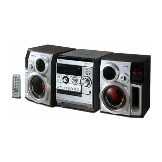
FRONT SPEAKERS SX-NR80
Speaker system 4 way, Built-in subwoofer (magnetic
shielded)
Speaker units Subwoofer: 160 mm cone
Mid range: 80 mm cone
Tweeter: 50 mm cone
Super tweeter: 20 mm ceramic
Impedance 6 ohms
Dimensions (W x H x D) 266 x 324 x 259 mm
Weight 5.7 kg
Specifications and external appearance are subject to change without
notice.
Page 8
! = ! SAFTY PARTS
C = Components marked
All components used on this model at the production line are shown in this service manual.
However, please note that not all components will be available as spare parts for after-sales service.
Components marked S and O are designated as spare parts for service and will be stocked at the spare parts centers.
Components marked X and R are not designated as spare parts for after sales service, and will not be stocked at the spare parts centers.
UNIT-NAME ! C REF-NO PARTS-NO PARTS-NAME SUFFIX&MODEL
-9-
CX-SNR80
VSM
FRONT S D 0302 87-A40-291-080 DIODE,1N4148M (CPT) a
FRONT S D 0601 87-A40-269-080 C-DIODE,MC2836 a
FRONT S D 0658 87-A40-269-080 C-DIODE,MC2836 a
FRONT X D 0702 88-100-000-010 PLATING-JW, 0.58 SN95 a
FRONT X D 0703 88-100-000-010 PLATING-JW, 0.58 SN95 a
FRONT S D 0801 87-A40-291-080 DIODE,1N4148M (CPT) a
FRONT S D 0981 87-A40-291-080 DIODE,1N4148M (CPT) a
FRONT S D 0985 87-A40-291-080 DIODE,1N4148M (CPT) a
FRONT O FFC0104 88-911-101-110 FF-CABLE,11P 1.25 100MM a
FRONT O FFC0202 88-904-201-110 FF-CABLE,4P 1.25 a
FRONT O FFC0731 88-908-301-110 FF-CABLE,8P 1.25 300MM a
FRONT O FL 0901 8C-NF5-603-010 FL,HUA-11MM42T a
FRONT S IC 0601 87-070-289-040 C-IC,BU2092F a
FRONT S IC 0901 8C-NF5-601-130 C-IC,UPD780226GF-034-3BA a
FRONT S IC 0961 87-A21-831-010 IC,SPS-442-1-F1 a
FRONT O JR 0601 88-108-101-080 C-RES,U 100-1/16W J a
FRONT O JR 0605 88-108-101-080 C-RES,U 100-1/16W J a
FRONT O JR 0609 88-108-101-080 C-RES,U 100-1/16W J a
FRONT O JR 0617 88-108-101-080 C-RES,U 100-1/16W J a
FRONT X JW 0937 88-121-101-080 RES,100-1/8W J a
CX-SNR80
VSM
FRONT O L 0951 87-A50-655-010 COIL,CLK 4.19MHZ (TOKO)7KLY a
FRONT O LED0201 87-A41-062-040 LED,LTL-1CHEE-012A RED a
FRONT O LED0205 87-A41-062-040 LED,LTL-1CHEE-012A RED a
FRONT O LED0206 87-A41-062-040 LED,LTL-1CHEE-012A RED a
FRONT O LED0207 87-A41-062-040 LED,LTL-1CHEE-012A RED a
FRONT O LED0208 87-A41-062-040 LED,LTL-1CHEE-012A RED a
FRONT S Q 0102 87-A30-076-080 C-TR,2SC3052F a
FRONT S Q 0103 87-A30-538-040 C-TR,SRA2202S a
FRONT S Q 0104 87-A30-538-040 C-TR,SRA2202S a
FRONT S Q 0301 87-A30-494-080 TR,2SA1980G a
FRONT S Q 0302 87-A30-076-080 C-TR,2SC3052F a
FRONT S Q 0303 87-A30-076-080 C-TR,2SC3052F a
FRONT S Q 0601 87-A30-495-080 TR,2SA1981Y a
FRONT S Q 0602 87-A30-495-080 TR,2SA1981Y a
FRONT S Q 0603 89-112-965-080 TR,2SA1296GR a
FRONT S Q 0801 87-A30-076-080 C-TR,2SC3052F a
FRONT S Q 0803 87-A30-288-040 C-TR,DTC114YKA a
FRONT S Q 0804 87-A30-288-040 C-TR,DTC114YKA a
FRONT S Q 0805 87-A30-288-040 C-TR,DTC114YKA a
FRONT S Q 0806 87-A30-076-080 C-TR,2SC3052F a
CX-SNR80
VSM
FRONT S Q 0901 87-A30-538-040 C-TR,SRA2202S a
FRONT O R 0109 88-108-224-080 C-RES,U 220K-1/16W J a
FRONT O R 0110 88-108-153-080 C-RES,U 15K-1/16W J a
FRONT X R 0111 88-108-333-080 C-RES,U 33K-1/16W J a
FRONT O R 0112 88-108-224-080 C-RES,U 220K-1/16W J a
FRONT O R 0114 88-108-103-080 C-RES,U 10K-1/16W J a
FRONT O R 0115 88-108-153-080 C-RES,U 15K-1/16W J a
FRONT X R 0116 88-108-104-080 C-RES,U 100K-1/16W J a
FRONT X R 0151 88-100-000-010 PLATING-JW, 0.58 SN95 a
FRONT X R 0152 88-100-000-010 PLATING-JW, 0.58 SN95 a
FRONT X R 0153 88-128-821-080 C-RES, 820-1/8W J a
FRONT X R 0154 88-128-821-080 C-RES, 820-1/8W J a
FRONT O R 0155 88-108-332-080 C-RES,U 3.3K-1/16W J a
FRONT O R 0156 88-108-332-080 C-RES,U 3.3K-1/16W J a
FRONT X R 0160 88-108-000-080 C-JUMPER,U a
FRONT X R 0161 88-108-000-080 C-JUMPER,U a
FRONT X R 0162 88-108-000-080 C-JUMPER,U a
FRONT X R 0163 88-108-000-080 C-JUMPER,U a
FRONT X R 0164 88-108-000-080 C-JUMPER,U a
FRONT X R 0165 88-108-000-080 C-JUMPER,U a
CX-SNR80
VSM
FRONT X R 0166 88-108-000-080 C-JUMPER,U a
FRONT X R 0206 88-128-102-080 C-RES, 1K-1/8W J a
FRONT X R 0207 88-128-102-080 C-RES, 1K-1/8W J a
FRONT X R 0208 88-128-102-080 C-RES, 1K-1/8W J a
FRONT X R 0211 88-121-102-080 RES,1K-1/8W J a
FRONT X R 0212 88-121-102-080 RES,1K-1/8W J a
FRONT X R 0213 88-121-103-080 RES,10K-1/8W J a
FRONT X R 0215 88-121-103-080 RES,10K-1/8W J a
FRONT X R 0216 88-121-103-080 RES,10K-1/8W J a
FRONT X R 0217 88-108-472-080 C-RES,U 4.7K-1/16W J a
FRONT X R 0218 88-121-101-080 RES,100-1/8W J a
FRONT X R 0301 88-108-104-080 C-RES,U 100K-1/16W J a
FRONT X R 0302 88-108-472-080 C-RES,U 4.7K-1/16W J a
FRONT O R 0303 88-108-153-080 C-RES,U 15K-1/16W J a
FRONT O R 0304 88-108-102-080 C-RES,U 1K-1/16W J a
FRONT X R 0306 88-108-471-080 C-RES,U 470-1/16W J a
FRONT O R 0321 88-108-103-080 C-RES,U 10K-1/16W J a
FRONT O R 0322 88-108-102-080 C-RES,U 1K-1/16W J a
FRONT X R 0323 88-108-821-080 C-RES,U 820-1/16W J a
FRONT X R 0324 88-121-122-080 RES,1.2K-1/8W J a
ELECTRICAL PARTS LIST — 2/15
3.0
Rated 3 out of 5
3 out of 5 stars (based on 1 review)
Your overall rating
AIWA NSX-R80 (01) PDF MANUAL
Click here to download AIWA NSX-R80 (01) PDF MANUAL
AIWA NSX-R80 (01) PDF MANUAL
FREE ENGLISH PDF
OPERATING INSTRUCTIONS
USER GUIDE – USER MANUAL
OWNER GUIDE – OWNER MANUAL
REFERENCE GUIDE – REFERENCE MANUAL
INSTRUCTION GUIDE – INSTRUCTION MANUAL
Your overall rating
- YouTube
AIWA NSX-R80 (01) PDF MANUAL
AIWA NSX-R80 (01) PDF MANUAL
-
Руководства по ремонту
1

AIWA NSX-R80 V(S) сервис-мануал
(56 страниц)
-
Тип:
PDF -
Размер:
6.38 MB
Просмотр
AIWA NSX-R80 V(S) (Домашняя аудиотехника) сервис мануалы в PDF-формате помогут найти неполадки и ошибки, а также осуществить ремонт AIWA NSX-R80 V(S) и восстановить работу устройства.