-
Contents
-
Table of Contents
-
Bookmarks
Quick Links
User Guide
Capacity Controller
AK-PC 551
ADAP-KOOL® Refrigeration Control System
Related Manuals for Danfoss AK-PC 551
Summary of Contents for Danfoss AK-PC 551
-
Page 1
User Guide Capacity Controller AK-PC 551 ADAP-KOOL® Refrigeration Control System… -
Page 2: Operation
The controller contains several languages. Select the preferred language at start-up. Data communication The controller has built-in modbus data communication, and it can be connected to an AK-SM 800 type system device. User Guide RS8GY302 © Danfoss 2015-06 AK-PC 551…
-
Page 3: Suction Group
In this way, the total electrical load in the store is limited. The threshold value may not be set lower than the compressor’s lowest capacity step/”Start speed”. AK-PC 551 User Guide RS8GY302 © Danfoss 2015-06…
-
Page 4
If controlling a media temperature, the control sensor must be set to S7. This temperature sensor must be located in the desired medium. The Pc pressure transmitter must also be installed. It is used for high-pressure monitoring. User Guide RS8GY302 © Danfoss 2015-06 AK-PC 551… -
Page 5: Safety Functions
Sd from a Copeland digital scroll, a Copeland stream or Bitzer CRII the capacity will be increased so that the compressor can cool down itself ). The compressors will be stopped if the temperature nears the set max. temperature value. AK-PC 551 User Guide RS8GY302 © Danfoss 2015-06…
-
Page 6: Display Overview
By clicking the right arrow you can see these three displays: Active alarms Cleared Alarms Information on the controller When an alarm is sent from the controller, you must advance to this display to see the alarm text. User Guide RS8GY302 © Danfoss 2015-06 AK-PC 551…
-
Page 7: Setup Overview
When the Plant type has None been selected, it will al- low several settings to be made. For example: Continue to the next menus. All settings are explained on the pages that follow. AK-PC 551 User Guide RS8GY302 © Danfoss 2015-06…
-
Page 8
• Severe alarm • All alarms (In the event of an alarm, the sound generator can be stopped by moving across the active alarm screen; see page 6) Suction A Control status Regulation status User Guide RS8GY302 © Danfoss 2015-06 AK-PC 551… -
Page 9
At start-up, the cooling system must have time to cool down before PI regulation takes over Min: 0 s Max: 300 s the regulation role and can cut in the next compressor. Fac: 120 s Set the time before the next compressor may be started here. AK-PC 551 User Guide RS8GY302 © Danfoss 2015-06… -
Page 10
Set the period time for the unloader valve (on time + off time) Fac: 20 s CRII Period time **: For CRII Min: 10 s Max: 20 s Set the period time for the unloader valve (on time + off time) Fac: 60 s User Guide RS8GY302 © Danfoss 2015-06 AK-PC 551… -
Page 11
Min: 1 min. Max: 60 min Set the forced Off-time during which the compressor must be off before it can be Fac: 4 min switched on again. The setting is to prevent incorrect operation. AK-PC 551 User Guide RS8GY302 © Danfoss 2015-06… -
Page 12
Min: -25°C (-1.0 bar) Max: 90°C (159 bar) Also set a value if regulating with a fluid reference (set point value used in the event of an Fac: 35°C (15.0 bar) outside temperature sensor error). User Guide RS8GY302 © Danfoss 2015-06 AK-PC 551… -
Page 13
Define whether a heat recovery cycle should be started with a signal on a DI input here. DI-demand • No: No function Yes / No • Yes: A DI input is reserved. When a signal is registered, the heat recovery function reference Fac: No will become active. AK-PC 551 User Guide RS8GY302 © Danfoss 2015-06… -
Page 14
When a sensor error has occurred, an O.K. signal must be registered within a specified Fac: 10 min. number of minutes before the controller resets the alarm. The regulation will be resumed as soon as the sensor signal is O.K. User Guide RS8GY302 © Danfoss 2015-06 AK-PC 551… -
Page 15
If you log out here without waiting for the time-out period to elapse, go to the overview display and hold down the “X” button for 3 seconds. Display contrast Adjust contrast Min: 0 Max: 100 Fac: 30 AK-PC 551 User Guide RS8GY302 © Danfoss 2015-06… -
Page 16
Select an input and continue on into the setting. In the final setting you will have be able to select which function you wish to connect to the input. User Guide RS8GY302 © Danfoss 2015-06 AK-PC 551… -
Page 17
Disable: Alarms set to this priority level will be cancelled. High pressure: Factory setting for the alarm can be seen on page 21. Compressor safety: Suction group B Low pressure: High pressure: Compressor safety: Condenser High pressure: Fan safety: AK-PC 551 User Guide RS8GY302 © Danfoss 2015-06… -
Page 18
20 to 35 display screens, depending on what is selected along the way. The selection will also result in a connection to a given input and output. You yourself will see this connection in the IO configuration menu. If applicable, see page 20. User Guide RS8GY302 © Danfoss 2015-06 AK-PC 551… -
Page 19
AK-PC 551 User Guide RS8GY302 © Danfoss 2015-06… -
Page 20
• Saux for general thermostat in “IO configuration”. Here is an example of 3 compressors and 3 fans: In this image you can see how many outputs and inputs your settings have provided. User Guide RS8GY302 © Danfoss 2015-06 AK-PC 551… -
Page 21: Alarm List
If you have corrected the sensor error and want to perform a manual, forced removal of the alarm, go to the “Alarm detail display” Press and hold the “X” key for 2 seconds here. AK-PC 551 User Guide RS8GY302 © Danfoss 2015-06…
-
Page 22
9. Press the X key to return to the Bios menu 10. Select the “Application” menu and press Enter. The display will once again retrieve data from the controller. This process will take about 5 minutes. User Guide RS8GY302 © Danfoss 2015-06 AK-PC 551… -
Page 23
• Ratiometric: 10-90% of supply, AKS 32R • Signal: 1-5 V, AKS 32 Temperature sensor 0-20mA • Pt 1000 ohm, AKS 11 or AKS 21. 4-20mA AKS 33 • NTC 86K ohm @ 25°C, from digital scroll AK-PC 551 User Guide RS8GY302 © Danfoss 2015-06… -
Page 24
As a result, the evaporators will not be filled with fluid that can be led to a compressor when the regulation process restarts. One of the compressor control relays can be used for this function, or the function can be prompted via data communication. User Guide RS8GY302 © Danfoss 2015-06 AK-PC 551… -
Page 25: External Display
24 V 080G0294 MMIGRS2 Display unit With buttons and display Wire for display unit, L = 1.5 m, 1 pcs. 080G0075 080G0076 Wire for display unit, L = 3 m, 1 pcs. AK-PC 551 User Guide RS8GY302 © Danfoss 2015-06…
-
Page 26: Mounting Dimensions
Danfoss can accept no responsibility for possible errors in catalogues, brochures and other printed material. Danfoss reserves the right to alter its products without notice. This also applies to products already on order provided that such alternations can be made without subsequential changes being necessary in specifications already agreed.
Контроллер AK-PC 551 используется для регулирования холодопроизводительности компрессоров и конденсаторов в холодильных системах. Может регулироваться работа максимум 8 компрессоров и одного конденсатора. В контроллере предусмотрена передача данных с помощью сети Modbus, и он может быть подключен к системному устройству типа AK-SС 355, АК-SM 800.
Документация
Ежедневная эксплуатация может настраиваться непосредственно с помощью контроллера или с помощью внешнего дисплейного устройства. Во время настройки экраны дисплея могут задаваться таким образом, что только необходимые параметры будут появляться для дополнительных настроек и выполнения операций конечным пользователем. Функции управления защищены паролем, и может быть предоставлено три уровня доступа. В контроллере предусматривается использование нескольких языков. Требуемый язык может быть выбран при вводе в эксплуатацию.
| Напряжение питания | 24 В пер. тока +/-15% 50/60 Гц, 17ВА 24 В пост. тока (20-60 В), 17ВА 230 В пер. тока (85-265 В) 50/60 Гц, 20 ВА |
|
| 8 аналоговых входов | Измерение давления: Измерительный преобразователь давления с выходом отношения напряжений, модель AKS 32R Измерительный преобразователь давления 1-5 В, модель AKS 32 Измерительный преобразователь давления 0-20 (4-20) мА, модель AKS 33 |
|
| Измерение температуры Pt 1000 Ом / 0 °C NTC — 86K для компрессоров типа Digital Scroll / Stream |
||
| 8 дискретных входов | Сигнал от сухих контактов для выполнения, например, следующих функций: Пуск / останов регулирования Мониторинг цепей защиты Предупредительный сигнал общего назначения |
|
| Релейный выход для регулирования холодопроизводительности | 4 шт. SPDT (8 А) | AC-1: 6 А (активная нагрузка) AC-15: 4 А (индуктивная нагрузка) |
| 2 шт. SPST (16 АA) | AC-1: 10 А (активная нагрузка) AC-15: 3,5 (индуктивная нагрузка) |
|
| 2 шт. полупроводниковых реле ШИМ для Scroll — разгрузки |
Imax. = 0,5 А Imin. = 50 мА Утечка <1,5 мА |
|
| 2 выхода напряжения | 0-10 В пост. тока Ri = 1 кОм Требуется отдельное питание 24 В |
|
| Выход для дисплея | Для типа MMIGRS2 | |
| Передача данных | Modbus для AK-SM 850 | |
| Условия окружающей среды | -20 — 60 °C при эксплуатации -40 — 70 °C при перевозке |
|
| Относительная влажность 20 — 80%, без конденсации | ||
| Отсутствие ударов и вибрации | ||
| Степень защиты | IP 20 | |
| Масса | 0,2 кг | |
| Монтаж | На DIN-рейку | |
| Клеммы подключения | Для многожильных проводов сечением макс. 2,5 мм2 | |
| Сертификация | Выполнение требований директив ЕС для низковольтного оборудования и электромагнитной совместимости с целью маркировки знаком CE Испытания на соответствие требованиям директивы для низковольтного оборудования в соответствии с EN 60730-1 и EN 60730-2-9 Испытания на соответствие требованиям директивы для электромагнитной совместимости в соответствии с EN61000-6-2 и 3 |

Introduction
Application
The controller is used for capacity regulation of compressors
and condensers in small refrigeration applications. A maximum of
8 compressors and one condenser can be regulated. For example:
• One suction group + one condenser group
• Two suction groups + one shared condenser (max. 4 + 4 steps)
• One compressor group, max. 8 steps
• One condenser group, max. 8 steps
Advantages
• Energy savings via:
— Optimisation of suction pressure
— Night time increase
— Floating condensing pressure
— Load limitation
Input and output
There are a limited number of available inputs and outputs.
For each signal type, though, the following can be connected:
• Analogue inputs, max. 8 pcs.
Signal from pressure transmitters, temperature sensors,
voltage signal, etc.
• Digital inputs, max. 8 pcs.
Signal from automatic safety control, day/night signal, etc.
• Relay outputs, max. 6 pcs.
Connection of compressors, condenser fans
• Solid state outputs, max. 2 pcs.
— Control of capacity valve on a Copeland digital scroll
— Control of unloader on a Copeland stream compressor.
— Control of both unloaders on a Bitzer CRII
If the outputs are not used for these functions, they can be used
as ordinary relay outputs
• Analogue outputs, max. 2 pcs.
Speed control of compressors or condenser fans.
The daily operation can be set up directly on the controller or
via an external display device.
During set-up, the display images will be adjusted so that only
the relevant images are opened for additional setting and
end-user operation.
The operation is password protected, and three levels of
access can be granted.
The controller contains several languages. Select the preferred
language at start-up.
Data communication
The controller has built-in modbus data communication, and it
can be connected to an AK-SM 800 type system device.
2
User Guide RS8GY302 © Danfoss 2015-06
AK-PC 551
 |
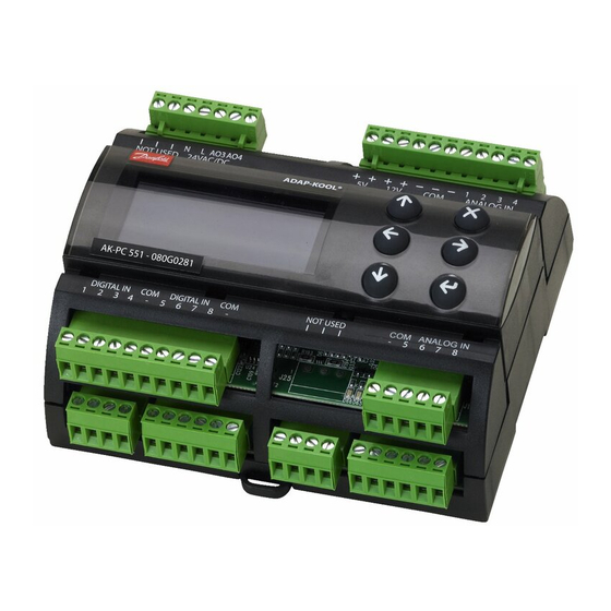
[Page 1] Danfoss AK-PC 551 Capacity Controller AK-PC 551 User Guide ADAP-KOOL® Refrigeration Control System |
 |
[Page 2] Danfoss AK-PC 551 2 User Guide RS8GY302 © Danfoss 2015-06 AK-PC 551 Introduction Application The controller is used for capacity regulation of compressors and condensers in small refrigeration applications. A maximum of 8 compressors and one condenser can be re… |
 |
[Page 3] Danfoss AK-PC 551 AK-PC 551 User Guide RS8GY302 © Danfoss 2015-06 3 Suction Group Compressor types The following types of compressors can be used for regulation: • Single-step compressors (one can be speed-regulated) • Compressor with unloaders • Scroll compr… |
 |
[Page 4] Danfoss AK-PC 551 4 User Guide RS8GY302 © Danfoss 2015-06 AK-PC 551 Condenser Fan control The fans can be controlled incrementally using the controller’s relays, or they can be speed-controlled via the controller’s analogue output. Speed control can be via … |
 |
[Page 5] Danfoss AK-PC 551 AK-PC 551 User Guide RS8GY302 © Danfoss 2015-06 5 Safety functions Min./max. suction pressure Po The suction pressure is recorded continuously. If the measured value falls below the set minimum limit, the compressors will immediately cut out. I… |
 |
[Page 6] Danfoss AK-PC 551 6 User Guide RS8GY302 © Danfoss 2015-06 AK-PC 551 Display overview End-user overview The images in this daily user interface will depend on how the set-up is made. They will illustrate what is regulated. For example: One or two suction groups, o… |
 |
[Page 7] Danfoss AK-PC 551 AK-PC 551 User Guide RS8GY302 © Danfoss 2015-06 7 Wizard Here you will be led through a series of settings, after which the controller will be ready for start. Image 1 of 28 is displayed here. Quick Select from the dierent combinations of comp… |
 |
[Page 8] Danfoss AK-PC 551 8 User Guide RS8GY302 © Danfoss 2015-06 AK-PC 551 Start/stop Main switch Main switch Start and stop regulating here. The conguration settings will require that regulating is stopped. If you try to enter a conguration setting when regulating… |
 |
[Page 9] Danfoss AK-PC 551 AK-PC 551 User Guide RS8GY302 © Danfoss 2015-06 9 Control status Read the status of the control circuit here e.g.: • No comp. — No compressor capacity available • Normal ctrl — Normal control • Alarm Comp. — Cannot start compressor due to al… |
 |
[Page 10] Danfoss AK-PC 551 10 User Guide RS8GY302 © Danfoss 2015-06 AK-PC 551 Pump down Pump-down function To avoid too many compressor starts/stops at a low load, it is possible to dene a pump- down function for the last compressor. In this case, the compressor will be … |
 |
[Page 11] Danfoss AK-PC 551 AK-PC 551 User Guide RS8GY302 © Danfoss 2015-06 11 Comp. 1 min cap. *: For scroll and CRII Minimum capacity in the time period (without a minimum capacity the compressor will not be cooled) Min: 10% Max: 50% Fac: 10% Comp. 1 start cap *: For sc… |
 |
[Page 12] Danfoss AK-PC 551 12 User Guide RS8GY302 © Danfoss 2015-06 AK-PC 551 Comp. Safety delay Delay time before compressors cut out for reasons of safety The time begins when a signal is received on the DI input (congure the DI input via “Conguration” and “… |
 |
[Page 13] Danfoss AK-PC 551 AK-PC 551 User Guide RS8GY302 © Danfoss 2015-06 13 Sc3 oset Temperature oset for regulation with uid reference. Regulation reference = Sc3 measurement + Sc3 oset Min: 0 K Max: 20 K Fac: 6 K Min. reference Set the lowest permissible reg… |
 |
[Page 14] Danfoss AK-PC 551 14 User Guide RS8GY302 © Danfoss 2015-06 AK-PC 551 Fan status Fan status Fan speed Here a reading of the desired condenser fan capacity is provided in % VSD start/stop Fan operation (frequency converter) status can be read here Fan 1 The status o… |
 |
[Page 15] Danfoss AK-PC 551 AK-PC 551 User Guide RS8GY302 © Danfoss 2015-06 15 General functions Digital input alarms General on/o alarm Here you can dene up to 3 alarms that are not related to the regulation function. When a signal is received on the input, the con… |
 |
[Page 16] Danfoss AK-PC 551 16 User Guide RS8GY302 © Danfoss 2015-06 AK-PC 551 Password Access code The settings in the controller can be protected with three levels of access codes. Level 1: End user settings, such as changing the weekly plan Level 2: Adjusting installer l… |
 |
[Page 17] Danfoss AK-PC 551 AK-PC 551 User Guide RS8GY302 © Danfoss 2015-06 17 Analog outputs 3: 4: 0-10 V outputs When a function has been dened that needs to use a variable voltage outlet, it will be pos- sible to select this function on one of the available AO outputs… |
 |
[Page 18] Danfoss AK-PC 551 18 User Guide RS8GY302 © Danfoss 2015-06 AK-PC 551 Quick setup Quick congurations This setting will reserve inputs and outputs for the following compressors and fans: The various connections are shown on the next page. App. no. Display Suction … |
 |
[Page 19] Danfoss AK-PC 551 AK-PC 551 User Guide RS8GY302 © Danfoss 2015-06 19 App. no. Display Output Input On/O Analog Analog Digital DO1 DO2 DO3 DO4 DO5 DO6 DO7 DO8 AO3 AO4 AI1 AI2 AI3 AI4 AI5 AI6 AI7 AI8 DI1 DI2 DI3 DI4 DI5 DI6 DI7 DI8 17 3CDA + 2CB + FS C1A C2A C3A … |
 |
[Page 20] Danfoss AK-PC 551 20 User Guide RS8GY302 © Danfoss 2015-06 AK-PC 551 Connections when using Setup Wizard If you have used the Setup Wizard for the conguration, the controller will automatically assign the selected functions to inputs and outputs in accordance w… |
 |
[Page 21] Danfoss AK-PC 551 AK-PC 551 User Guide RS8GY302 © Danfoss 2015-06 21 Alarm list Alarm text Reason Priority setting Default value General alarms Standby mode (Main sw. OFF) Alarm when control is stopped by internal or external Main Switch (DI input «Main Swit… |
 |
[Page 22] Danfoss AK-PC 551 22 User Guide RS8GY302 © Danfoss 2015-06 AK-PC 551 ERR31 Alarm on the external display — MMIGRS2 If the communication to the display is not carried out correctly, it will send an “ERR31” error notication. This may be caused by the displa… |
 |
[Page 23] Danfoss AK-PC 551 AK-PC 551 User Guide RS8GY302 © Danfoss 2015-06 23 Connections DO DO1 DO2 DO3 DO4 DO5 DO6 DO7 DO8 Σ 1-8 I Max. 10 A (3.5) 10 A (3.5) 6 A (4) 6 A (4) 0.5 A min. 50 mA Io < 1,5 mA 0.5 A min. 50 mA Io < 1,5 mA 6 A (4) 6 A (4) 32 A U All … |
 |
[Page 24] Danfoss AK-PC 551 24 User Guide RS8GY302 © Danfoss 2015-06 AK-PC 551 The capacity is divided into period times as «PWM period time». 100% capacity is delivered when cooling takes place for the whole pe- riod. An o time is required by the bypass valve w… |
 |
[Page 25] Danfoss AK-PC 551 AK-PC 551 User Guide RS8GY302 © Danfoss 2015-06 25 Ordering Type Function Operation Supply voltage Code no. AK-PC 551 Capacity controller With buttons and display 230 V 080G0281 24 V 080G0283 With external display and 1.5 m wire for display unit… |
 |
[Page 26] Danfoss AK-PC 551 26 User Guide RS8GY302 © Danfoss 2015-06 AK-PC 551 List of literature Installation guide for extended operation RC8AC Here you can see how a data communication connection to ADAP- KOOL® Refrigeration control systems can be established. ADAP-KOOL�… |
- Холодильное оборудование
- Контроллеры


| Артикул | 080G0282 |
| id товара | 10265 |
| Страна | Дания  |
| Минимальный заказ | 1 шт |
| В наличии на складах | 0 шт |
Общее описание
Контролеры AK-PC 551 предназначены для регулирования производительности компрессорной станции и конденсаторов до 8 ступеней.
Технические
характеристикиДополнительная
информацияМодельный
ряд
Характеристика
| Назначение | Для агрегатов |
| Производитель | Danfoss |
| Марка | Adap-Kool |
| Количество релейных выходов | 8 |
| Напряжение питания | 230В |
| Дисплей | Внешний |
Дополнительная информация
Инструкция AK-PC551 Danfoss (1.75Mb)
Полезные ссылки
Сайт производителя Danfoss
Модельный ряд


Контроллер производительности AK-PC 351
- Артикул: 080G0289
- Страна: Китай

- В наличии: нет
Контроллер AK-PC351, предназначен для управления холодильными централями с одним конденсатором и до четырех компрессоров. Имеет 4 аналоговых входа, 5 релейных выходов, 2 выхода 0…10B, 8 дискретных выходов для пуск/останов регулирования ,мониторинг цепей защиты, предупредительный сигнал общего назначения. Напряжение питания 24В постоянного или переменного тока.

Контроллер AK-PC 520
- Артикул: 084B8012
- Страна: Дания
- В наличии: нет
Контролеры AK-PC 520 предназначены для регулирования производительности компрессоров и конденсаторов в небольших холодильных системах.

Контроллер AK-PC 530 (пром. упаковка)
- Артикул: 084B8007
- Страна: Дания
- В наличии: 1 шт
Контролеры AK-PC 530 (EKC 531D1) предназначены для регулирования производительности компрессоров и конденсаторов в небольших холодильных системах.

Контроллер AK-PC 551
- Артикул: 080G0282
- Страна: Дания
- В наличии: нет
Контролеры AK-PC 551 предназначены для регулирования производительности компрессорной станции и конденсаторов до 8 ступеней.

Контроллер AK-PC 551, 24В (комплект)
- Артикул: 080G0288
- Страна: Дания
- В наличии: нет
AK-PC 551 используется для управления мощностью компрессоров и конденсаторов в холодильных системах среднего размера и охватывает приложения с одной или двумя группами всасывания и конденсатором. Может управлять до 8 компрессоров в одной группе всасывания, и он может управлять компрессорами 4×4 в 2 группах всасывания. Поддерживается множество комбинаций компрессоров, включая переменную скорость, цифровые прокрутки и 4-цилиндровые компрессоры Stream. Вентиляторы конденсаторов могут управляться шагами (макс.  или с переменной скоростью. AK-PC 551 может быть полностью сконфигурирован с помощью встроенного или удаленного дисплея. Гибкая конфигурация 8 цифровых выходов, 8 аналоговых входов, 8 цифровых входов и 2 аналоговых выхода позволяет контроллеру легко адаптироваться к любому пакетному приложению.

Контроллер AK-PC 551 (080G0283)
- Артикул: 080G0283
- Страна: Дания
- В наличии: нет
Контролеры AK-PC 551 предназначены для регулирования производительности компрессорной станции и конденсаторов до 8 ступеней. Имеется ограниченное количество доступных входов и выходов. Для каждого типа сигналов могут быть использованы следующие подключения: Аналоговые входы, макс. 8 входов. Сигналы от датчиков давления, датчиков температуры, сигнал напряжения и т.д. Подключение компрессоров, вентиляторов конденсаторов

Контроллер AK-PC 551 (080G0281)
- Артикул: 080G0281
- Страна: Дания
- В наличии: нет
Универсальный контроллер для больших централей. особенности: зуммер, компрессор безопасности, разрядка газа темп. безопасность, безопасность вентилятора, давление плавающего конденсатора, функция рекуперации тепла, встроенный ЖК-дисплей безопасности высокого давления, сброс нагрузки, безопасность низкого давления, оптимизация ночью, оптимизация P0, часы реального времени, температура всасываемого газа.

Контроллер производительности AK-PC 560
- Артикул: 084B8013
- Страна: Китай
- В наличии: 1 шт
Контроллер AK-PC 560, предназначен для управления холодильными централями с одним конденсатором и до четырех компрессоров. Имеет 4 аналоговых входа, 5 релейных выходов, 2 выхода 0…10B, 8 дискретных выходов для пуск/останов регулирования ,мониторинг цепей защиты, предупредительный сигнал общего назначения. Напряжение питания 24В постоянного или переменного тока.

Контроллер AK-PC 651
- Артикул: 080G0312
- Страна: Дания
- В наличии: нет
Контролеры AK-PC 651 предназначены для регулирования производительности компрессорной станции и конденсаторов, например до 10 компрессоров и одного конденсатора. Встроенный дисплей, кнопки на панели.

Контроллер AK-PC 781
- Артикул: 080Z0186
- Страна: Дания
- В наличии: нет
Контролеры AK-PC 781 предназначены для регулирования производительности холодильных агрегатов с рекуперацией тепла. Поддержка подключений: IO Extension, LON RS485, RJ45 (RS232) to PC/ Display.
Контроллер AK-PC 781A
- Артикул: 080Z0191
- Страна: Дания
- В наличии: нет
Контролеры AK-PC 781A предназначены для регулирования производительности компрессоров и конденсаторов в небольших холодильных системах.