-
Contents
-
Table of Contents
-
Bookmarks
Quick Links
User Manual
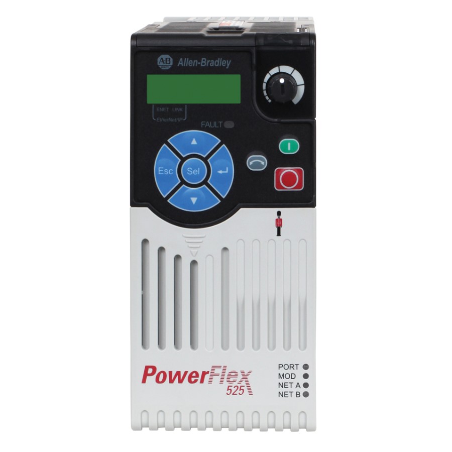
PowerFlex 525 Adjustable Frequency AC Drive
Original Instructions
Related Manuals for Allen-Bradley PowerFlex 525
Summary of Contents for Allen-Bradley PowerFlex 525
-
Page 1
User Manual PowerFlex 525 Adjustable Frequency AC Drive Original Instructions… -
Page 2: Important User Information
IMPORTANT Identifies information that is critical for successful application and understanding of the product. Allen-Bradley, Rockwell Automation, Rockwell Software, PowerFlex, Connected Components Workbench, Studio 5000, DriveTools SP, AppView, CustomView, MainsFree Programming, and PointStop are trademarks of Rockwell Automation, Inc. Trademarks not belonging to Rockwell Automation are property of their respective companies.
-
Page 3: Table Of Contents
Table of Contents Important User Information ……..2 Preface Overview Who Should Use this Manual .
-
Page 4
Table of Contents Advanced Display Group ……… 94 Advanced Program Group . -
Page 5
EMC Instructions……….208 Using PowerFlex 525 Safe-Torque-Off……208 Safety Concept. -
Page 6
Table of Contents Notes: Rockwell Automation Publication 520-UM001A-EN-E — February 2013… -
Page 7: Preface
Guarding Against Electrostatic Damage 8000-4.5.2 The following publications provide specific PowerFlex 520-Series information on drive installation, features, specifications, and service: Title Publication PowerFlex 525 AC Drive Specifications 520-TD001 PowerFlex Dynamic Braking Resistor Calculator PFLEX-AT001 PowerFlex AC Drives in Common Bus Configurations DRIVES-AT002…
-
Page 8: Manual Conventions
Drive as; drive, PowerFlex 520, PowerFlex 520 Drive or PowerFlex 520 AC drive. • Specific drives within the PowerFlex 520-Series may be referred to as: – PowerFlex 525, PowerFlex 525 drive or PowerFlex 525 AC drive. • Parameter numbers and names are shown in this format: P 031 [Motor NP Volts]…
-
Page 9: Drive Frame Sizes
Overview Preface Drive Frame Sizes Similar PowerFlex 525 drive sizes are grouped into frame sizes to simplify spare parts ordering, dimensioning, etc. A cross reference of drive catalog numbers and their respective frame sizes is provided in Appendix General Precautions ATTENTION: The drive contains high voltage capacitors which take time to discharge after removal of mains supply.
-
Page 10: Catalog Number Explanation
Rating Enclosure Reserved Emission Class Reserved Dash Dash Code Braking Standard Code Type 25B PowerFlex 525 Code EMC Filter No Filter Filter Code Voltage Phase Code Interface Module 120V AC 1 Standard 240V AC 1 240V AC 3 480V AC 3…
-
Page 11: Installation/Wiring
Chapter Installation/Wiring This chapter provides information on mounting and wiring the PowerFlex 525 drive. For information on… See page… Mounting Considerations AC Supply Source Considerations General Grounding Requirements Fuses and Circuit Breakers Power and Control Module Control Module Cover Power Module Terminal Guard…
-
Page 12
Chapter 1 Installation/Wiring • Do not expose to a corrosive atmosphere. • Protect from moisture and direct sunlight. Minimum Mounting Clearances Appendix B for mounting dimensions. Vertical Vertical, Zero Stacking Vertical with Control Module Fan Kit Vertical, Zero Stacking with No clearance between drives. -
Page 13
Installation/Wiring Chapter 1 Ambient Operating Temperatures Appendix B for option kits. Mounting Enclosure Rating Ambient Temperature Minimum Maximum (No Derate) Maximum (Derate) Maximum with (3)(5) Control Module Fan Kit (Derate) 50 °C (122 °F) 60 °C (140 °F) 70 °C (158 °F) Vertical IP 20/Open Type 45 °C (113 °F) -
Page 14
Chapter 1 Installation/Wiring Derating Guidelines for High Altitude The drive can be used without derating at a maximum altitude of 1000 m (3300 ft). If the drive is used above 1000 m (3300 ft): • Derate the maximum ambient temperature by 5 °C (41 °F) for every additional 1000 m (3300 ft), subject to limits listed in the Altitude Limit (Based on Voltage) -
Page 15: Ac Supply Source Considerations
AC Supply Source Ungrounded Distribution Systems Considerations ATTENTION: PowerFlex 525 contains protective MOVs that are referenced to ground. These devices must be disconnected if the drive is installed on an ungrounded or resistive grounded distribution system. ATTENTION: Removing MOVs in drives with an embedded filter will also disconnect the filter capacitor from earth ground.
-
Page 16: General Grounding Requirements
Chapter 1 Installation/Wiring Input Power Conditioning The drive is suitable for direct connection to input power within the rated voltage of the drive (see Appendix A). Listed in the Input Power Conditions table below are certain input power conditions which may cause component damage or reduction in product life.
-
Page 17
Installation/Wiring Chapter 1 Ground Fault Monitoring If a system ground fault monitor (RCD) is to be used, only Type B (adjustable) devices should be used to avoid nuisance tripping. Safety Ground — (PE) This is the safety ground for the drive that is required by code. One of these points must be connected to adjacent building steel (girder, joist), a floor ground rod or bus bar. -
Page 18: Fuses And Circuit Breakers
Installation/Wiring Fuses and Circuit Breakers The PowerFlex 525 drive does not provide branch short circuit protection. This product should be installed with either input fuses or an input circuit breaker. National and local industrial safety regulations and/or electrical codes may determine additional requirements for these installations.
-
Page 19
Installation/Wiring Chapter 1 Rockwell Automation Publication 520-UM001A-EN-E — February 2013… -
Page 20
Chapter 1 Installation/Wiring Rockwell Automation Publication 520-UM001A-EN-E — February 2013… -
Page 21
Installation/Wiring Chapter 1 Rockwell Automation Publication 520-UM001A-EN-E — February 2013… -
Page 22: Power And Control Module
Chapter 1 Installation/Wiring Power and Control Module PowerFlex 525 drives consists of a Power Module and Control Module. Separating the Power and Control Module 1. Press and hold down the catch on both sides of the frame cover, then pull out and swing upwards to remove (Frames B…E only).
-
Page 23
Installation/Wiring Chapter 1 3. Hold the sides and top of the Control Module firmly, then pull out to separate it from the Power Module. Connecting the Power and Control Module 1. Align the connectors on the Power Module and Control Module, then push the Control Module firmly onto the Power Module. -
Page 24
Chapter 1 Installation/Wiring 2. Push the top cover of the Control Module towards the Power Module to lock it. 3. Insert the catch at the top of the frame cover into the Power Module, then swing the frame cover to snap the side catches onto the Power Module (Frames B…E only). -
Page 25: Control Module Cover
Installation/Wiring Chapter 1 Control Module Cover To access the control terminals, DSI port, and Ethernet port, the front cover must be removed. To remove: 1. Press and hold down the arrow on the front of the cover. 2. Slide the front cover down to remove from the Control Module. Re-attach the front cover when wiring is complete.
-
Page 26: Power Wiring
Chapter 1 Installation/Wiring 2. Press and hold down the locking tab on the terminal guard. 3. Slide the terminal guard down to remove from the Power Module. Re-attach the terminal guard when wiring is complete. To access the power terminals for Frame A, you need to separate the Power and Control Modules.
-
Page 27
Installation/Wiring Chapter 1 UL installations above 50 °C ambient must use 600V, 90 °C wire. UL installations in 50 °C ambient must use 600V, 75 °C or 90 °C wire. UL installations in 40 °C ambient should use 600V, 75 °C or 90 °C wire. Use copper wire only. -
Page 28
Chapter 1 Installation/Wiring the overall drive performance. Unless specified in the individual distance tables as tested with the drive, these cables are not recommended and their performance against the lead length limits supplied is not known. Recommended Shielded Wire Location Rating/Type Description Standard (Option 1) 600V, 90 °C (194 °F) XHHW2/RHW-2… -
Page 29: Power Terminal Block
Installation/Wiring Chapter 1 Power Terminal Block Power Terminal Block Frame A, B, C & D Frame E L1/R L2/S L3/T T1/U T2/V T3/W L1/R L2/S L3/T T1/U T2/V T3/W DC- DC+ Terminal Description L1/R, L2/S, L3/T Input Line Voltage Connection T1/U, T2/V, T3/W Motor Phase Connection = Switch any two motor leads to change forward direction.
-
Page 30: Common Bus/Precharge Notes
Chapter 1 Installation/Wiring Common Bus/Precharge If drives are used with a disconnect switch to the common DC bus, then an auxiliary contact on the disconnect must be connected to a digital input of the Notes drive. The corresponding input (parameter t062, t063, t065…t068 [DigIn TermBlk xx]) must be set to 30, “Precharge En”…
-
Page 31
Installation/Wiring Chapter 1 Recommended Signal Wire Signal Type/ Belden Wire Type(s) Description Min. Insulation Where Used (or equivalent) Rating Analog I/O & PTC 8760/9460 0.750 mm (18 AWG), twisted pair, 300V, 60 °C (140 °F) 100% shield with drain Remote Pot 8770 0.750 mm (18 AWG), 3 conductor, shielded… -
Page 32: Control I/O Terminal Block
Chapter 1 Installation/Wiring Control I/O Terminal Block Control I/O Wiring Block Diagram Typical Typical SRC wiring SNK wiring Stop Safety 1 DigIn TermBlk 02/ Start/Run FWD Safe-Torque-Off Safety 2 DigIn TermBlk 03/ Direction/Run REV Safety +24V Digital Common DigIn TermBlk 05 DigIn TermBlk 06 DigIn TermBlk 07/Pulse DigIn TermBlk 0…
-
Page 33
Installation/Wiring Chapter 1 t064 [2-Wire Mode] Normal Stop I/O Terminal 01 Stop 0 “Edge Trigger” Per P045 Coast [Stop Mode] 1 “Level Sense” Per P045 [Stop Mode] 2 “Hi-Spd Edge” Coast 3 “Momentary” Per P045 [Stop Mode] The drive is shipped with a jumper installed between I/O Terminals 01 and 11. IMPORTANT Remove this jumper when using I/O Terminal 01 as a stop or enable input. -
Page 34
Chapter 1 Installation/Wiring Control I/O Terminal Designations No. Signal Default Description Parameter 13 ±10V In Not Active For external 0-10V (unipolar) or ±10V (bipolar) input supply or P047, P049, potentiometer wiper. t062, t063, t065, t066, Input impedance: t093, A459, Voltage source = 100 kΩ A471 Allowable potentiometer resistance range = 1…10 kΩ… -
Page 35
Installation/Wiring Chapter 1 Connection Example Analog Input Bipolar Unipolar (Voltage) Unipolar (Current) 0-10V, 100k Ω impedance P047 [Speed Reference1] P047 [Speed Reference1] P047 [Speed Reference1] 4-20 mA, 250 Ω = 5 “0-10V Input” and = 5 “0-10V Input” = 6 “4-20mA Input” t093 [10V Bipolar Enbl] impedance… -
Page 36
Chapter 1 Installation/Wiring Connection Example 2 Wire SNK Control — Internal Supply (SNK) Non-Reversing Stop-Run 2 Wire SRC Control — Internal Supply (SRC) External Supply (SRC) Run FWD/Run REV P046 [Start Source 1] = 2, t062 [DigIn TermBlk 02] = 48 and t063 [DigIn Stop-Run Forward TermBlk 03] = 50… -
Page 37
Installation/Wiring Chapter 1 Connection Example 3 Wire SRC Control — Internal Supply (SRC) External Supply (SRC) Reversing P046 [Start Source 1] = 2, Stop t062 [DigIn TermBlk 02] Stop = 49 and t063 [DigIn TermBlk 03] = 51 Start A momentary input will Start Direction start the drive. -
Page 38
Chapter 1 Installation/Wiring Typical Multiple Drive Connection Examples Input/Output Connection Example Multiple Digital Input Connections Customer Inputs can be wired per External Supply (SRC). Customer Inputs Optional Ground Connection When connecting a single input such as Run, Stop, Reverse or Preset Speeds to multiple drives, it is important to connect I/O Terminal 04 common together for all drives. -
Page 39: Start And Speed Reference Control
Installation/Wiring Chapter 1 Start and Speed Reference Start Source and Speed Reference Selection Control The start and drive speed command can be obtained from a number of different sources. By default, start source is determined by P046 [Start Source 1] and drive speed source is determined by P047 [Speed Reference1].
-
Page 40
Chapter 1 Installation/Wiring Digital Input Selection for Start Source If P046, P048 P050 [Start Source x] has been set to 2, “DigIn TermBlk”, then t062 t063 [DigIn TermBlk xx] must be configured for 2-Wire or 3-Wire control for the drive to function properly. [Start Source x] Start and Direction [DigIn TermBlk… -
Page 41: Ce Conformity
Directive has been demonstrated using harmonized European Norm (EN) standards published in the Official Journal of the European Communities. PowerFlex 525 drives comply with the EN standards listed below when installed according to the installation instructions in this manual. CE Declarations of Conformity are available online at: http://www.rockwellautomation.com/products/certification/.
-
Page 42
• For CE compliance, drives must satisfy installation requirements related to both EN 61800-5-1 and EN 61800-3 provided in this document. • PowerFlex 525 drives must be installed in a pollution degree 1 or 2 environment to be compliant with the CE LV Directive. See… -
Page 43
Installation/Wiring Chapter 1 • PowerFlex 525 drives are not intended to be used on public low-voltage networks which supply domestic premises. Without additional mitigation, radio frequency interference is expected if used on such a network. The installer is responsible to take measures such as a supplementary line filter… -
Page 44
• Motor cabling must be separated from control and signal wiring wherever possible. • Maximum motor cable length must not exceed the maximum length indicated in PowerFlex 525 RF Emission Compliance and Installation Requirements on page 45 for compliance with radio frequency emission limits for the specific standard and installation environment. -
Page 45
Building structure steel (1) Some installations require a shielded enclosure. Keep wire length as short as possible between the enclosure entry point and the EMI filter. PowerFlex 525 RF Emission Compliance and Installation Requirements Filter Type Standard/Limits EN61800-3 Category C1… -
Page 46
Chapter 1 Installation/Wiring Additional Installation Requirements Frame Size Class C1 Class C2 Enclosure and Conduit Cable EMC Cores Required Enclosure EMC Cores Required (Input and Output) 380…480V AC (-15%, +10%) – 3-Phase Input with Internal EMC Filter, 0…460V 3-Phase Output –… -
Page 47: Start Up
Chapter Start Up This chapter describes how to start up the PowerFlex 525 drive. To simplify drive setup, the most commonly programmed parameters are organized in a single Basic Program Group. For information on… See page… Prepare for Drive Start-Up…
-
Page 48
Chapter 2 Start Up 4. Verify that the Sink (SNK)/Source (SRC) jumper is set to match your control wiring scheme. See the Control I/O Wiring Block Diagram on page 32 for location. The default control scheme is Source (SRC). The Stop terminal is jumpered to IMPORTANT allow starting from the keypad or comms. -
Page 49: Display And Control Keys
Start Up Chapter 2 Display and Control Keys Menu Parameter Group and Description Basic Display Commonly viewed drive operating conditions. ENET LINK Basic Program EtherNet/IP Commonly used programmable functions. Terminal Blocks Programmable terminal functions. Communications Programmable communication functions. Logic Programmable logic functions. Advanced Display Advanced drive operating conditions.
-
Page 50: Viewing And Editing Parameters
Chapter 2 Start Up Name Description Reverse Used to reverse direction of the drive. Default is active. Controlled by parameters P046, P048 and P050 [Start Source x] and A544 [Reverse Disable]. Start Used to start the drive. Default is active. Controlled by parameters P046, P048 and P050 [Start Source x].
-
Page 51: Drive Programming Tools
[Output Freq] is displayed. Press Enter or Sel to enter the group list again. Some features in the PowerFlex 525 drive are not supported by older Drive Programming Tools configuration software tools. It is strongly recommended that customers using such tools migrate to RSLogix 5000 (version 17.0 or greater) or Logix Designer…
-
Page 52: Smart Start-Up With Basic Program Group Parameters
– Czech – – The PowerFlex 525 drive is designed so that start up is simple and efficient. The Smart Start-Up with Basic Basic Program Group contains the most commonly used parameters. See Program Group Parameters Programming and Parameters on page 57 for detailed descriptions of the parameters listed here, as well as the full list of available parameters.
-
Page 53: Lcd & Scrolling Description
Use parameter A556 [Text Scroll] to set the speed at which the text scrolls across the display. Select 0 “Off ” to turn off text scrolling. See Language Support on page 51 for the languages supported by PowerFlex 525. Rockwell Automation Publication 520-UM001A-EN-E — February 2013…
-
Page 54: Usb
Chapter 2 Start Up The PowerFlex 525 drive has a USB port that connects to a PC for the purpose of upgrading drive firmware or uploading/downloading a parameter configuration. You do not need to power up the control module. Simply connect the PowerFlex 525 drive to your PC with a USB Type B cable, and you will benefit from MainsFree™…
-
Page 55
Start Up Chapter 2 Double-click on the PF52XUSB.EXE file to launch the USB utility application. The main menu is displayed. Follow the program instructions to upgrade the firmware or upload/download configuration data. Make sure your PC is powered by an AC power outlet or has a fully charged IMPORTANT battery before starting any operation. -
Page 56
Chapter 2 Start Up Notes: Rockwell Automation Publication 520-UM001A-EN-E — February 2013… -
Page 57: Programming And Parameters
Chapter Programming and Parameters This chapter provides a complete listing and description of the PowerFlex 525 parameters. Parameters are programmed (viewed/edited) using either the drive’s built-in keypad, RSLogix 5000 version 17.0 or greater, Logix Designer version 21.0 or greater, or Connected Components Workbench version 3.0 or greater software.
-
Page 58: About Parameters
Chapter 3 Programming and Parameters About Parameters To configure a drive to operate in a specific way, drive parameters may have to be set. Three types of parameters exist: • ENUM ENUM parameters allow a selection from 2 or more items. Each item is represented by a number.
-
Page 59
Programming and Parameters Chapter 3 Logic Stp Logic 4 L184 Stp Logic Time 4 L194 Step Units 2 L204 Step Units 6 L212 Stp Logic 5 L185 Stp Logic Time 5 L195 Step Units F 2 L205 Step Units F 6 L213 Stp Logic 6 L186… -
Page 60
F684 Drv 1 Logic Cmd F709 AppView Parameter Groups PowerFlex 525 drives include various AppView™ parameter groups that groups certain parameters together for quick and easy access based on different types of applications. See AppView Parameter Groups on page 126 for more information. -
Page 61
Programming and Parameters Chapter 3 Centrifugal Pump Motor OL Current P033 Start Source 1 P046 Anlg In4-20mA Hi t096 PID 1 Diff Rate A463 Motor NP FLA P034 Speed Reference1 P047 Anlg In mA Loss t097 PID 1 Setpoint A464 Motor NP Poles P035 Relay Out1 Sel… -
Page 62
Chapter 3 Programming and Parameters CustomView Parameter Group PowerFlex 525 drives include a CustomView™ parameter group for you to store frequently used parameters for your application. See CustomView Parameter Group on page 127 for more information. Custom Group This group can store up to 100 parameters. -
Page 63: Basic Display Group
Programming and Parameters Chapter 3 Basic Display Group b001 [Output Freq] Related Parameter(s): b002, b010, P043, P044, P048, P050, P052 Output frequency present at T1, T2 & T3 (U, V & W). Does not include slip frequency. Values Default: Read Only Min/Max: 0.00/[Maximum Freq] Display:…
-
Page 64
Chapter 3 Programming and Parameters Basic Display Group (continued) b007 [Fault 1 Code] Related Parameter(s): F604-F610 b008 [Fault 2 Code] b009 [Fault 3 Code] A code that represents a drive fault. Codes appear in these parameters in the order they occur (b007 [Fault 1 Code] = the most recent fault). -
Page 65
Programming and Parameters Chapter 3 Basic Display Group (continued) b013 [Contrl In Status] Related Parameter(s): b002, P044, P045 State of the digital terminal blocks 1…3 and DB transistor. IMPORTANT Actual control commands may come from a source other than the control terminal block. 1 = Closed State, 0 = Open State DigIn TBlk 1 Digit 1… -
Page 66
Chapter 3 Programming and Parameters Basic Display Group (continued) b018 [Power Saved] Related Parameter(s): b017 Instantaneous power savings of using this drive compared to an across the line starter. Values Default: Read Only Min/Max: 0.00/655.35 kW Display: 0.01 kW b019 [Elapsed Run time] Related Parameter(s): A555 Accumulated time drive is outputting power. -
Page 67
Programming and Parameters Chapter 3 Basic Display Group (continued) b025 [Accum Cost Sav] Related Parameter(s): b024, P052, A555 Total approximate accumulated cost savings of the drive compared to using an across the line starter. [Accum Cost Sav] = [Average kWh cost] x [Accum kWh Sav] Values Default: Read Only… -
Page 68: Basic Program Group
Chapter 3 Programming and Parameters Basic Program Group P030 [Language] Language Support Selects the language displayed. A reset or power cycle is required after selection is made. HIM/LCD Display RSLogix 5000/ Connected Logix Designer Components Workbench Options 1 English (Default) 2 Français 3 Español 4 Italiano…
-
Page 69
Programming and Parameters Chapter 3 Basic Program Group (continued) P035 [Motor NP Poles] Related Parameter(s): b015 Sets the number of poles in the motor. Values Default: Min/Max: 2/40 Display: P036 [Motor NP RPM] Stop drive before changing this parameter. Sets the rated nameplate rpm of the motor. Used to calculate the rated slip of the motor. To reduce the slip frequency, set this parameter closer to the motor synchronous speed. Values Default: 1750 rpm… -
Page 70
Chapter 3 Programming and Parameters Basic Program Group (continued) P041 [Accel Time 1] Related Parameter(s): P044, A439 Sets the time for the drive to accelerate from 0 Hz to P044 [Maximum Freq]. Accel Rate = [Maximum Freq] / [Accel Time x] [Maximum Freq] Speed [Accel Time x]… -
Page 71
Programming and Parameters Chapter 3 Basic Program Group (continued) P045 [Stop Mode] Related Parameter(s): t086, t087, A434, A435 Determines the stopping mode used by the drive when a stop is initiated. Options 0 “Ramp, CF” (Default) Ramp to Stop. Stop command clears active fault. 1 “Coast, CF”… -
Page 72
Chapter 3 Programming and Parameters Basic Program Group (continued) P047 [Speed Reference1] Related Parameter(s): C125 P049 [Speed Reference2] P051 [Speed Reference3] Selects the source of speed command for the drive. Changes to these inputs take effect as soon as they are entered. P047 [Speed Reference1] is the factory default speed reference unless overridden. -
Page 73: Terminal Block Group
Programming and Parameters Chapter 3 Terminal Block Group t062 [DigIn TermBlk 02] t063 [DigIn TermBlk 03] Related Parameter(s): b012, b013, b014, P045, P046, P048, P049, P050, P051, t064, t065 [DigIn TermBlk 05] t066 [DigIn TermBlk 06] t086, A410-A425, A427, A431, A432, A433, A434, A435, t067 [DigIn TermBlk 07] t068 [DigIn TermBlk 08] A442, A443, A488, A535, A560, A562, A563, A567,…
-
Page 74
Chapter 3 Programming and Parameters Options 27 “Anlg Invert” Inverts the scaling of the analog input levels set in t091 [Anlg In 0-10V Lo] and t092 [Anlg In 0-10V Hi] or t095 [Anlg In4-20mA Lo] and t096 [Anlg In4-20mA Hi]. 28 “EM Brk Rlse”… -
Page 75
Programming and Parameters Chapter 3 Options 47 Reserved 48 “2-Wire FWD” [DigIn TermBlk 02] default. Selects 2-Wire FWD for this input. (only for DigIn TermBlk 02) Select this option and set P046, P048 P050 [Start Source x] to 2 “DigIn TrmBlk” to configure [Start Source x] to a 2-wire run forward mode. -
Page 76
Chapter 3 Programming and Parameters Terminal Block Group (continued) ì t069 [Opto Out1 Sel] Related Parameter(s): P046, P048, P050, t070, t073, t077, t082, t072 [Opto Out2 Sel] t086, t087, t093, t094, t097, A541, A564 Determines the operation of the programmable digital outputs. Options Setting Output Changes State When… -
Page 77
Programming and Parameters Chapter 3 Terminal Block Group (continued) t070 [Opto Out1 Level] Related Parameter(s): t069, t072 t073 [Opto Out2 Level] 32 bit parameter. Determines the on/off point for the digital outputs when t069 t072 [Opto Outx Sel] is set to the values shown below. Min/Max Value Range Based On [Opto Outx Sel] Setting 6: 0…500 Hz 10: 0…100%… -
Page 78
Chapter 3 Programming and Parameters Terminal Block Group (continued) t076 [Relay Out1 Sel] Related Parameter(s): P046, P048, P050, t070, t073, t077, t082, t081 [Relay Out2 Sel] t086, t087, t093, t094, t097, A541, A564 Determines the operation of the programmable output relay. Options Output Relay Changes State When… -
Page 79
Programming and Parameters Chapter 3 Terminal Block Group (continued) t077 [Relay Out1 Level] Related Parameter(s): t076, t081 t082 [Relay Out2 Level] 32 bit parameter. Determines the on/off point for the output relay when t076 t081 [Relay Outx Sel] is set to the values shown below. Min/Max Value Range Based On [Relay Outx Sel] Setting 6: 0…500 Hz 10: 0…100%… -
Page 80
Chapter 3 Programming and Parameters Terminal Block Group (continued) t087 [EM Brk On Delay] Related Parameter(s): P045 Sets the time the drive remains at minimum frequency (after releasing the brake coil relay) before stopping if EM Brake Control Mode is enabled with P045 [Stop Mode]. -
Page 81
Programming and Parameters Chapter 3 Terminal Block Group (continued) t089 [Analog Out High] Scales the maximum output value (V or mA) when the source setting is at maximum. Values Default: 100% Min/Max: 0/800% Display: t090 [Anlg Out Setpt] Related Parameter(s): t088 Sets the percentage of output desired when t088… -
Page 82
Chapter 3 Programming and Parameters Terminal Block Group (continued) t094 [Anlg In V Loss] Related Parameter(s): P043, P044, A426, A427 Sets the response to a loss of input. When the 0-10V input (or –10 to +10V) is used for any reference, any input less than 1V is reported as a signal loss. Input must exceed 1.5V for the signal loss condition to end. -
Page 83
Programming and Parameters Chapter 3 Terminal Block Group (continued) t098 [Anlg Loss Delay] Related Parameter(s): t094, t097 Sets the length of time after power-up during which the drive detects no analog signal loss. Response to an analog signal loss is set in t094 t097 [Analog In x Loss]. -
Page 84
Chapter 3 Programming and Parameters Terminal Block Group (continued) t104 [Wake Time] Sets the analog input time the drive must stay above to wake from sleep mode. Values Default: 0.0 s Min/Max: 0.0/600.0 s Display: 0.1 s t105 [Safety Open En] Sets the action when both safety inputs (Safety 1 and Safety 2) are disabled (de-energized –… -
Page 85: Communications Group
Programming and Parameters Chapter 3 Communications Group C121 [Comm Write Mode] Saves parameter values in active drive memory (RAM) or in drive non-volatile memory (EEPROM). ATTENTION: If Automatic Drive Configuration (ADC) is used, this parameter must remain at its default value of 0 “Save”. IMPORTANT Parameter values set prior to setting 1 “RAM only”…
-
Page 86
Chapter 3 Programming and Parameters Communications Group (continued) C127 [RS485 Format] Determines the details related to the specific Modbus protocol used by the drive. A reset or power cycle is required after selection is made. Options 0 “RTU 8-N-1” (Default) 1 “RTU 8-E-1”… -
Page 87
Programming and Parameters Chapter 3 Communications Group (continued) C137 [EN Gateway Cfg 1] Related Parameter(s): C128 C138 [EN Gateway Cfg 2] C139 [EN Gateway Cfg 3] C140 [EN Gateway Cfg 4] Sets the bytes of the gateway address. A reset or power cycle is required after selection is made. 192.168.1.1 [EN Gateway Cfg 1] [EN Gateway Cfg 2]… -
Page 88
Chapter 3 Programming and Parameters Communications Group (continued) C144 [EN Idle Flt Actn] Related Parameter(s): P045, C145, C146, C147-C150 Sets the action that the EtherNet/IP interface and drive takes if the EtherNet/IP interface detects that the scanner is idle because the controller was switched to program mode. ATTENTION: Risk of injury or equipment damage exists. -
Page 89
Programming and Parameters Chapter 3 Communications Group (continued) C157 [EN Data Out 1] C158 [EN Data Out 2] C159 [EN Data Out 3] C160 [EN Data Out 4] Datalink parameter number whose value is read from the embedded EtherNet/IP data table. Values Default: Min/Max:… -
Page 90
Chapter 3 Programming and Parameters C175 [DSI I/O Cfg] Sets the configuration of the Drives that are active in the multi-drive mode. Identifies the connections that would be attempted on a reset or power cycle. A reset or power cycle is required after selection is made. -
Page 91: Logic Group
Programming and Parameters Chapter 3 Logic Group L180 [Stp Logic 0] L181 [Stp Logic 1] Related Parameter(s): L182 [Stp Logic 2] L183 [Stp Logic 3] L184 [Stp Logic 4] L185 [Stp Logic 5] L186 [Stp Logic 6] L187 [Stp Logic 7] Stop drive before changing this parameter.
-
Page 92
Chapter 3 Programming and Parameters StepLogic Settings The logic for each function is determined by the four digits for each StepLogic parameter. The following is a listing of the available settings for each digit. See Appendix D for more information. Logic for next step Digit 1 Logic to jump to a different step… -
Page 93
Programming and Parameters Chapter 3 Logic Group (continued) L190 [Stp Logic Time 0] L191 [Stp Logic Time 1] L192 [Stp Logic Time 2] L193 [Stp Logic Time 3] L194 [Stp Logic Time 4] L195 [Stp Logic Time 5] L196 [Stp Logic Time 6] L197 [Stp Logic Time 7] Sets the time to remain in each step if the corresponding command word is set to “Step based on time”. -
Page 94: Advanced Display Group
Chapter 3 Programming and Parameters Advanced Display Group d360 [Analog In 0-10V] Related Parameter(s): t091, t092 Displays the 0-10V analog input as a percent of full scale. Values Default: Read Only Min/Max: 0.0/100.0% Display: 0.1% d361 [Analog In 4-20mA] Related Parameter(s): t095, t096 Displays the 4-20 mA analog input as a percent of full scale.
-
Page 95
Programming and Parameters Chapter 3 Advanced Display Group (continued) d368 [Testpoint Data] Related Parameter(s): A483 Displays the present value of the function selected in A483 [Testpoint Sel]. Values Default: Read Only Min/Max: 0/FFFF Display: d369 [Motor OL Level] Displays the motor overload counter. Values Default: Read Only… -
Page 96
Chapter 3 Programming and Parameters Advanced Display Group (continued) d382 [Torque Current] Displays the current value of the motor torque current measured by the drive. Values Default: Read Only Min/Max: 0.00/(Drive Rated Amps x 2) Display: 0.01 A d383 [PID1 Fdbk Displ] d385 [PID2 Fdbk Displ] Displays the active PID Feedback value. -
Page 97
Programming and Parameters Chapter 3 Advanced Display Group (continued) d390 [Fiber Status] Present status of the Fibers features. 1 = Condition True, 0 = Condition False Sync Hold Digit 1 Sync Ramp Digit 2 Traverse On Digit 3 Traverse Dec Digit 4 Not Used Values… -
Page 98: Advanced Program Group
Chapter 3 Programming and Parameters Advanced Program Group A410 [Preset Freq 0] A411 [Preset Freq 1] A412 [Preset Freq 2] A413 [Preset Freq 3] A414 [Preset Freq 4] A415 [Preset Freq 5] A416 [Preset Freq 6] A417 [Preset Freq 7] A418 [Preset Freq 8] A419 [Preset Freq 9] A420 [Preset Freq 10]…
-
Page 99
Programming and Parameters Chapter 3 Advanced Program Group (continued) A428 [MOP Reset Sel] Determines if the current MOP reference command is saved on power down. Options 0 “Zero MOP Ref” Resets the MOP frequency to zero on power down. 1 “Save MOP Ref” (Default) A429 [MOP Preload] Determines the operation of the MOP function. -
Page 100
Chapter 3 Programming and Parameters Advanced Program Group (continued) A435 [DC Brake Level] Related Parameter(s): P045 Defines the maximum DC brake current, in amps, applied to the motor when P045 [Stop Mode] is set to either 4 “Ramp” or 6 “DC Brake”. Ramp-to-Stop Mode DC Injection Stop Mode [DC Brake Time]… -
Page 101
Programming and Parameters Chapter 3 Advanced Program Group (continued) A439 [S Curve %] Enables a fixed shape S-Curve that is applied to the acceleration and deceleration ramps (including jog). S-Curve Time = (Accel or Decel Time) x (S-Curve Setting in percentage) Example: 100% S-Curve 50% S-Curve… -
Page 102
Chapter 3 Programming and Parameters Advanced Program Group (continued) A442 [Accel Time 2] Related Parameter(s): P044 Time for the drive to ramp from 0.0 Hz to P044 [Maximum Freq] if Accel Time 2 is selected. Accel Rate = [Maximum Freq] / [Accel Time] [Maximum Freq] Speed [Accel Time x]… -
Page 103
Programming and Parameters Chapter 3 Advanced Program Group (continued) A449 [Skip Freq Band 1] Related Parameter(s): A448, A450, A452, A454 A451 [Skip Freq Band 2] A453 [Skip Freq Band 3] A455 [Skip Freq Band 4] Determines the band around A448, A450, A452 A454 [Skip Frequency x]. -
Page 104
Chapter 3 Programming and Parameters Advanced Program Group (continued) A458 [PID 1 Trim Sel] A470 [PID 2 Trim Sel] Stop drive before changing this parameter. Sets the PID output as trim to the source reference. Options 0 “Disabled” (Default) PID Trim is disabled. 1 “TrimOn Pot”… -
Page 105
Programming and Parameters Chapter 3 Advanced Program Group (continued) A460 [PID 1 Fdback Sel] A472 [PID 2 Fdback Sel] Selects the source of the PID feedback. Options 0 “0-10V Input” (Default) Note: PID does not function with bipolar input. Negative voltages are ignored and treated as zero. 1 “4-20mA Input”… -
Page 106
Chapter 3 Programming and Parameters Advanced Program Group (continued) A466 [PID 1 Preload] A478 [PID 2 Preload] Sets the value used to preload the integral component on start or enable. Values Default: 0.0 Hz Min/Max: 0.0/500.0 Hz Display: 0.1 Hz A467 [PID 1 Invert Err] A479 [PID 2 Invert Err] Changes the sign of the PID error. -
Page 107
Programming and Parameters Chapter 3 Advanced Program Group (continued) A486 [Shear Pin1 Level] Related Parameter(s): A487, A489 A488 [Shear Pin2 Level] Sets the value of current at which the shear pin fault occurs after the time set in A487, A489 [Shear Pin x Time]. -
Page 108
Chapter 3 Programming and Parameters Advanced Program Group (continued) A493 [Motor OL Select] Related Parameter(s): P032, P033 Drive provides Class 10 overload protection. Settings 0…2 select the derating factor for the I t overload function. No Derate Min Derate Max Derate % of [Motor NP Hertz] % of [Motor NP Hertz] % of [Motor NP Hertz]… -
Page 109
Programming and Parameters Chapter 3 Advanced Program Group (continued) A499 [Motor Lm] Mutual Inductance of induction motor. Values Default: Based on Drive Rating Min/Max: 0.0/6553.5 mH Display: 0.1 mH A500 [Motor Lx] Leakage Inductance of induction motor. Values Default: Based on Drive Rating Min/Max: 0.0/6553.5 mH Display:… -
Page 110
Chapter 3 Programming and Parameters Advanced Program Group (continued) A522 [Freq 1 Ki] Related Parameter(s): A509, A510 A524 [Freq 2 Ki] A526 [Freq 3 Ki] Sets I-gain of “Vector” control mode when in frequency region 1, 2 or 3 for faster speed response during steady-state where motor is at its rated speed. If A509 [Speed Reg Sel] is set to 1 “Manual”, these parameters can be changed. -
Page 111
Programming and Parameters Chapter 3 Advanced Program Group (continued) A531 [Start Boost] Related Parameter(s): P031, P032, P039, A530 Sets the boost voltage (% of P031 [Motor NP Volts]) and redefines the V/Hz curve when A530 [Boost Select] = 0 “Custom V/Hz” and P039 [Torque Perf Mode] = 0 “V/Hz”. -
Page 112
Chapter 3 Programming and Parameters Advanced Program Group (continued) A535 [Motor Fdbk Type] Related Parameter(s): A537 Stop drive before changing this parameter. Selects the encoder type. ATTENTION: The loss of analog input, encoder or other feedback may cause unintended speed or motion. Take appropriate precautions to guard against possible unintended speed or motion. -
Page 113
Programming and Parameters Chapter 3 Advanced Program Group (continued) A541 [Auto Rstrt Tries] Related Parameter(s): A542 Sets the maximum number of times the drive attempts to reset a fault and restart. See Chapter 4 for more information on faults and fault codes. Clear a Type 1 fault and restart the drive. -
Page 114
Chapter 3 Programming and Parameters Advanced Program Group (continued) A547 [Compensation] Enables/disables correction options that may improve problems with motor instability. Options 0 “Disabled” No compensation. 1 “Electrical” (Default) Some drive/motor combinations have inherent instabilities which are exhibited as non-sinusodial motor currents. This setting attempts to correct this condition 2 “Mechanical”… -
Page 115
Programming and Parameters Chapter 3 Advanced Program Group (continued) A554 [Drv Ambient Sel] Sets the maximum expected ambient of the drive when used above 50 °C. When ambient temperature is above 50 °C, the drive will apply necessary current derating. Options 0 “Normal”… -
Page 116
Chapter 3 Programming and Parameters Advanced Program Group (continued) A560 [Enh Control Word] Related Parameter(s): t062, t063, t065 — t068, A571 Allows control of positioning and other functions through parameter control for use over comms. The functions replicate the digital input options and function in the same way. 1 = Input Present, 0 = Input Not Present Home Limit Digit 1… -
Page 117
Programming and Parameters Chapter 3 Advanced Program Group (continued) A564 [Encoder Pos Tol] Sets the “At Position” and the “At Home’ tolerance around the encoder count. The value is added to and subtracted from the target encoder unit value to create the tolerance range. Values Default: Min/Max:… -
Page 118: Network Parameter Group
Chapter 3 Programming and Parameters Advanced Program Group (continued) A570 [P Jump] Related Parameter(s): A567 Sets the frequency amplitude that is added to or subtracted from the commanded frequency. See the diagram at A567 [Max Traverse]. Values Default: 0.00 Hz Min/Max: 0.00/300.00 Hz Display:…
-
Page 119: Fault And Diagnostic Group
Programming and Parameters Chapter 3 Fault and Diagnostic Group F604 [Fault 4 Code] Related Parameter(s): b007-b009 F605 [Fault 5 Code] F606 [Fault 6 Code] F607 [Fault 7 Code] F608 [Fault 8 Code] F609 [Fault 9 Code] F610 [Fault10 Code] A code that represents a drive fault. The codes appear in these parameters in the order they occur (b007 [Fault 1 Code] = the most recent fault). Repetitive faults are only recorded once. Values Default: Read Only…
-
Page 120
Chapter 3 Programming and Parameters Fault and Diagnostic Group (continued) F641 [Fault 1 Current] F642 [Fault 2 Current] Related Parameter(s): b003 F643 [Fault 3 Current] F644 [Fault 4 Current] F645 [Fault 5 Current] F646 [Fault 6 Current] F647 [Fault 7 Current] F648 [Fault 8 Current] F649 [Fault 9 Current] F650 [Fault10 Current]… -
Page 121
Programming and Parameters Chapter 3 Fault and Diagnostic Group (continued) F682 [Comm Sts — Opt] Displays the status of the internal communication to the drive. Digit 3 = “Internal Com option” 1 = Condition True, 0 = Condition False “Not Active (no connection)” Digit 1 “Internal option connected/active”… -
Page 122
Chapter 3 Programming and Parameters Fault and Diagnostic Group (continued) F686 [DSI I/O Act] Displays the Drives that are active in Multi-Drive mode. 1 = Drive Inactive, 0 = Drive Active Drive 0 Actv Digit 1 Drive 1 Actv Digit 2 Drive 2 Actv Digit 3 Drive 3 Actv… -
Page 123
Programming and Parameters Chapter 3 Fault and Diagnostic Group (continued) F697 [EN Subnet Act 1] F698 [EN Subnet Act 2] F699 [EN Subnet Act 3] F700 [EN Subnet Act 4] Shows the actual subnet mask used by the embedded EtherNet/IP interface at the time. This will indicate 0 if no address is set. 255.255.255.255 [EN Subnet Act 1] [EN Subnet Act 2]… -
Page 124
Chapter 3 Programming and Parameters Fault and Diagnostic Group (continued) F706 [Drv 0 Reference] F710 [Drv 1 Reference] F714 [Drv 2 Reference] F718 [Drv 3 Reference] F722 [Drv 4 Reference] In multi-drive mode, this is the reference being transmitted to drive 0/1/2/3/4. In single-drive mode, this is the reference being used by the drive (whether HS-DSI, EtherNet/IP, or DSI) at the time. -
Page 125
Programming and Parameters Chapter 3 Fault and Diagnostic Group (continued) F728 [EN Tx Packets] A count of the number of transmitted packets reported by the embedded EtherNet/IP interface. Values Default: Read Only Min/Max: 0/65535 Display: F729 [EN Tx Errors] A count of the number of transmit errors reported by the embedded EtherNet/IP interface. Values Default: Read Only… -
Page 126: Appview Parameter Groups
Chapter 3 Programming and Parameters AppView Parameter Groups PowerFlex 525 drives include various AppView parameter groups that groups certain parameters together for quick and easy access based on different types of applications. These applications include: • Conveyor • Mixer • Compressor •…
-
Page 127: Customview Parameter Group
Programming and Parameters Chapter 3 CustomView Parameter Use the CustomView parameter group to: • store frequently used parameters for your application for quicker access. Group • select only those parameters needed for your application and if required, hide all other parameters with A552 [Program Lock].
-
Page 128: Parameter Cross Reference By Name
Chapter 3 Programming and Parameters Parameter Cross Reference by Name Parameter Name Parameter Name Parameter Name 10V Bipolar Enbl DB Resistor Sel DSI Errors 2-Wire Mode DB Threshold DSI I/O Act Accel Time 1 DC Brake Level DSI I/O Cfg Accel Time 2 DC Brake Time Elapsed kWh…
-
Page 129
Programming and Parameters Chapter 3 Parameter Name Parameter Name Parameter Name EN Rx Overrruns Fault 6 Current HW Addr 2 EN Rx Packets Fault 6 Freq HW Addr 3 EN Subnet Act 1 Fault 6 Time-hr HW Addr 4 EN Subnet Act 2 Fault 6 Time-min HW Addr 5 EN Subnet Act 3… -
Page 130
Chapter 3 Programming and Parameters Parameter Name Parameter Name Parameter Name Output Voltage Preset Freq 13 Sleep Level Opto Out2 LevelF Preset Freq 14 Sleep Time Opto Out2 Sel Preset Freq 15 Sleep-Wake Sel Out Phas Loss En Preset Freq 2 Slip Hz Meter Output Current Preset Freq 3… -
Page 131
Programming and Parameters Chapter 3 Parameter Name Parameter Name Parameter Name Stp Logic 6 Stp Logic Time 6 Torque Perf Mode Stp Logic 7 Stp Logic Time 7 Traverse Dec Stp Logic Status Sync Time Traverse Inc Stp Logic Time 0 Testpoint Data Units Traveled H Stp Logic Time 1… -
Page 132
Chapter 3 Programming and Parameters Notes: Rockwell Automation Publication 520-UM001A-EN-E — February 2013… -
Page 133: Drive Status
Chapter Troubleshooting This chapter provides information to guide you in troubleshooting the PowerFlex 525 drive. Included is a listing and description of drive faults with possible solutions, when applicable. For information on… See page… Drive Status Faults Fault Descriptions Common Symptoms and Corrective Actions ATTENTION: Risk of injury or equipment damage exists.
-
Page 134
Chapter 4 Troubleshooting Fault Indication Condition Display Drive is indicating a fault. The integral LCD display provides visual notification of a fault condition by displaying the following. • Flashing fault number FAULT • Flashing fault indicator (LED) Press the Esc key to regain control of the display. Manually Clearing Faults Step Key(s) -
Page 135: Fault Descriptions
Troubleshooting Chapter 4 Auto Restart (Reset/Run) The Auto Restart feature provides the ability for the drive to automatically perform a fault reset followed by a start attempt without user or application intervention. This allows remote or “unattended” operation. Only certain faults are allowed to be reset.
-
Page 136
Chapter 4 Troubleshooting Fault Types, Descriptions and Actions No. Fault Type Description Action F015 Load Loss The output torque current is below the • Verify connections between motor value programmed in A490 [Load Loss and load. Level] for a time period greater than the •… -
Page 137
Troubleshooting Chapter 4 Fault Types, Descriptions and Actions No. Fault Type Description Action F081 DSI Comm Loss Communications between the drive and • Cycle power. the Modbus or DSI master device have • Check communications cabling. been interrupted. • Check Modbus or DSI setting. •… -
Page 138: Common Symptoms And Corrective Actions
Chapter 4 Troubleshooting Fault Types, Descriptions and Actions No. Fault Type Description Action F122 I/O Board Fail Failure has been detected in the drive • Cycle power. control and I/O section. • Replace drive or control module if fault cannot be cleared. F125 Flash Update Req The firmware in the drive is corrupt, Perform a firmware flash update…
-
Page 139
Incorrect input wiring. None • Wire inputs correctly and/or install jumper. • If the PowerFlex 525 Safe-Torque-Off function is used, verify that inputs are active. page 34 for wiring examples. • If 2-wire or 3-wire mode is used, verify that… -
Page 140
Chapter 4 Troubleshooting Drive does not respond to changes in speed command. Cause(s) Indication Corrective Action No value is coming from the source of the command. The drive “Run” indicator is • Check b012 [Control Source] for correct source. lit and output is 0 Hz. •… -
Page 141
Troubleshooting Chapter 4 Drive does not power up. Cause(s) Indication Corrective Action No input power to drive. None • Check the power circuit. • Check the supply voltage. • Check all fuses and disconnects. Control module is not connected properly to power module. None 1. -
Page 142
Chapter 4 Troubleshooting Notes: Rockwell Automation Publication 520-UM001A-EN-E — February 2013… -
Page 143: Drives, Fuse & Circuit Breaker Ratings
Appendix Supplemental Drive Information For information on… See page… Drives, Fuse & Circuit Breaker Ratings Specifications Drives, Fuse & Circuit Breaker The tables found in Fuses and Circuit Breakers on page 18 provide drive ratings and recommended AC line input fuse and circuit breaker information. Both Ratings types of short circuit protection are acceptable for UL and IEC requirements.
-
Page 144: Specifications
Appendix A Supplemental Drive Information Specifications Category PowerFlex 525 Certifications c-UL-us Listed to UL508C and CAN/CSA-C22.2 No. 14-05. C-Tick Australian Communications and Media Authority In conformity with the following: Radiocommunications Act: 1992 Radiocommunications Standard: 2008 N223 Radiocommunications Labelling Notice: 2008…
-
Page 145
Supplemental Drive Information Appendix A Category Specifications Protection Bus Overvoltage Trip 100…120V AC Input: 405V DC bus (equivalent to 150V AC incoming line) 200…240V AC Input: 405V DC bus (equivalent to 290V AC incoming line) 380…480V AC Input: 810V DC bus (equivalent to 575V AC incoming line) 525…600V AC Input: 1005V DC bus (equivalent to 711V AC incoming line) Bus Undervoltage Trip… -
Page 146
Appendix A Supplemental Drive Information Category Specifications Environment Sound Pressure Level (A-weighted) Measurements are taken 1 m from the drive. Frame A & B: Maximum 53 dBA Frame C: Maximum 57 dBA Frame D: Maximum 64 dBA Frame E: Maximum 68 dBA Electrical Voltage Tolerance: -15% / +10%… -
Page 147
(1) Non-Isolated 0-10V or 4-20 mA Specification Resolution: 10-bit 0-10V DC Analog: 1 k ohm minimum 4-20 mA Analog: 525 ohm maximum PowerFlex 525 Estimated Watts Loss (Rated Load, Speed & PWM) Voltage Output Current (A) Total Watts Loss 100…120V, 27.0 50/60 Hz 1-Phase 53.0 67.0… -
Page 148
Appendix A Supplemental Drive Information PowerFlex 525 Estimated Watts Loss (Rated Load, Speed & PWM) Voltage Output Current (A) Total Watts Loss 380…480V, 27.0 50/60 Hz 3-Phase 37.0 80.0 86.0 10.5 129.0 13.0 170.0 17.0 221.0 24.0 303.0 30.0 387.0 380…480V,… -
Page 149: Product Selection
Appendix Accessories and Dimensions Product Selection Catalog Number Description Drive Voltage Rating Rating Enclosure Emission Class Version PowerFlex 525 Drives Output Ratings Normal Duty Heavy Duty Output Input Frame Catalog No. Current (A) Voltage Range Size 100…120V AC (-15%, +10%) – 1-Phase Input, 0…230V 3-Phase Output 25B-V2P5N104 85…132…
-
Page 150
Appendix B Accessories and Dimensions PowerFlex 525 Drives Output Ratings Normal Duty Heavy Duty Output Input Frame Catalog No. Current (A) Voltage Range Size 380…480V AC (-15%, +10%) – 3-Phase Input with EMC Filter, 0…460V 3-Phase Output 25B-D1P4N114 323…528 25B-D2P3N114 0.75… -
Page 151
Accessories and Dimensions Appendix B Dynamic Brake Resistors Drive Ratings Minimum Resistance Resistance Input Voltage Ω ±10% Ω ±5% (1)(2) Catalog No. 100…120V AK-R2-091P500 50/60 Hz 0.75 AK-R2-091P500 1-Phase AK-R2-091P500 200…240V AK-R2-091P500 50/60 Hz 0.75 AK-R2-091P500 1-Phase AK-R2-091P500 AK-R2-047P500 200…240V AK-R2-091P500 50/60 Hz 0.75… -
Page 152
Appendix B Accessories and Dimensions EMC Line Filters Drive Ratings Input Voltage Current (A) Frame Size Catalog No. 100…120V 25-RF011-AL 50/60 Hz 0.75 25-RF023-BL 1-Phase 25-RF023-BL 200…240V 25-RF011-AL 50/60 Hz 0.75 25-RF011-AL 1-Phase 25-RF023-BL 11.0 25-RF023-BL 200…240V 25-RF014-AL 50/60 Hz 0.75 25-RF014-AL 3-Phase… -
Page 153
Accessories and Dimensions Appendix B Human Interface Module (HIM) Option Kits and Accessories Item Description Catalog No. LCD Display, Remote Panel Digital speed control 22-HIM-C2S Mount CopyCat capable IP66 (NEMA Type 4X/12) indoor use only Includes 2.9 meter cable LCD Display, Remote Digital speed control 22-HIM-A3 Handheld… -
Page 154
Appendix B Accessories and Dimensions Replacement Parts PowerFlex 520-Series Power Module Item Description PowerFlex 525 Power Replacement power module for use with PowerFlex 520-Series drives. Includes: Module • Power Module • Power Module Front Cover • Power Terminal Guard • Heatsink Fan… -
Page 155
32.0 446…660 25-PM1-E032 PowerFlex 520-Series Control Module Frame Item Description Size Catalog No. PowerFlex 525 Control Replacement control module for use with A…E 25B-CTM1 Module PowerFlex 520-Series drives. Includes: • Control Module • Control Module Front Cover Other Parts Frame… -
Page 156
AK-U0-RJ45-TR1 Terminal Block RJ45 Two position terminal block (5 pieces) AK-U0-RJ45-TB2P Connected Components Windows-based software packages for programming and http:// Workbench Software configuring Allen-Bradley drives and other Rockwell ab.rockwellautomation.co (Download or DVD-ROM) Automation products. m/programmable- controllers/connected- Compatibility: components-workbench- Windows XP, Windows Vista and Windows 7… -
Page 157: Product Dimensions
(3) Input line reactors were sized based on the NEC fundamental motor amps. Output line reactors were sized based on the VFD rated output currents. The PowerFlex 525 drive is available in five frame sizes. See PowerFlex 525 Drives Product Dimensions on page 149 for information on power ratings.
-
Page 158
Appendix B Accessories and Dimensions IP 20/Open Type – Frame A Dimensions are in millimeters and (inches) 72.0 (2.83) 172.0 (6.77) 57.5 (2.26) 6.0 (0.24) IP 20/Open Type – Frame B Dimensions are in millimeters and (inches) 87.0 (3.43) 172.0 (6.77) 72.5 (2.85) 6.0 (0.24) Rockwell Automation Publication 520-UM001A-EN-E — February 2013… -
Page 159
Accessories and Dimensions Appendix B IP 20/Open Type – Frame C Dimensions are in millimeters and (inches) 109.0 (4.29) 184.0 (7.24) 90.5 (3.56) 6.0 (0.24) IP 20/Open Type – Frame D Dimensions are in millimeters and (inches) 130.0 (5.12) 212.0 (8.35) 116.0 (4.57) 6.0 (0.24) Rockwell Automation Publication 520-UM001A-EN-E — February 2013… -
Page 160
Appendix B Accessories and Dimensions IP 20/Open Type – Frame E Dimensions are in millimeters and (inches) 185.0 (7.28) 279.0 (10.98) 160.0 (6.30) 7.6 (0.30) Rockwell Automation Publication 520-UM001A-EN-E — February 2013… -
Page 161
Accessories and Dimensions Appendix B IP 20/Open Type with Control Module Fan Kit – Frame A…E Dimensions are in millimeters and (inches) Frame A Frame B Frame C 109.0 (4.29) 72.0 (2.83) 87.0 (3.43) 72.5 (2.85) 57.5 (2.26) 90.5 (3.56) Frame D Frame E 196.0 (7.72) -
Page 162
Appendix B Accessories and Dimensions IP 30/NEMA 1/UL Type 1 – Frame A Dimensions are in millimeters and (inches) IP 30/NEMA 1/ UL Type 1 top panel 72.0 (2.83) 57.5 (2.26) 172.0 (6.77) 6.0 (0.24) IP 30/NEMA 1/ UL Type 1 conduit box 51.1 (2.01) 21.0 (0.82) ø21.5 (ø0.85) -
Page 163
Accessories and Dimensions Appendix B IP 30/NEMA 1/UL Type 1 – Frame B Dimensions are in millimeters and (inches) IP 30/NEMA 1/ UL Type 1 top panel 87.0 (3.43) 172.0 (6.77) 72.5 (2.85) 6.1 (0.24) IP 30/NEMA 1/ UL Type 1 conduit box 66.1 (2.60) 63.1 (2.48) 33.5 (1.32) -
Page 164
Appendix B Accessories and Dimensions IP 30/NEMA 1/UL Type 1 – Frame C Dimensions are in millimeters and (inches) IP 30/NEMA 1/ UL Type 1 top panel 109.0 (4.29) 90.5 (3.56) 184.0 (7.24) 6.0 (0.24) IP 30/NEMA 1/ UL Type 1 conduit box 80.5 (3.17) 66.5 (2.62) 34.5 (1.36) -
Page 165
Accessories and Dimensions Appendix B IP 30/NEMA 1/UL Type 1 – Frame D Dimensions are in millimeters and (inches) IP 30/NEMA 1/ UL Type 1 top panel 130.0 (5.12) 212.0 (8.35) 116.0 (4.57) 6.0 (0.24) IP 30/NEMA 1/ UL Type 1 conduit box 96.0 (3.78) 70.0 (2.76) 44.0 (1.73) -
Page 166
Appendix B Accessories and Dimensions IP 30/NEMA 1/UL Type 1 – Frame E Dimensions are in millimeters and (inches) IP 30/NEMA 1/ UL Type 1 top panel 185.0 (7.28) 160.0 (6.30) 279.0 (10.98) 7.6 (0.30) IP 30/NEMA 1/ UL Type 1 conduit box 127.5 (5.02) 82.5 (3.25) 62.5 (2.46) -
Page 167
Accessories and Dimensions Appendix B EMC Line Filter – Frame A Dimensions are in millimeters and (inches) Filter can be mounted onto the back of the drive. 55.0 (2.17) 72.0 (2.83) 30.0 (1.18) 54.0 (2.13) ø5.5 (ø0.22) 234.0 223.0 (9.21) 223.0 (8.78) (8.78) 20.0 (0.79) -
Page 168
Appendix B Accessories and Dimensions EMC Line Filter – Frame C Dimensions are in millimeters and (inches) Filter can be mounted onto the back of the drive. 70.0 (2.76) 109.0 (4.29) 37.0 (1.46) 76.0 (2.99) ø5.5 (ø0.22) 275.0 (10.83) 263.0 263.0 (10.35) (10.35) -
Page 169
Accessories and Dimensions Appendix B EMC Line Filter – Frame E Dimensions are in millimeters and (inches) 80.0 (3.15) 155.0 (6.10) 33.0 (1.30) 28.0 (1.10) 110.0 (4.33) ø5.5 (ø0.22) 390.0 (15.35) 375.0 375.0 (14.76) (14.76) 33.0 (1.30) 28.0 (1.10) 5.5 (0.22) 110.0 (4.33) Rockwell Automation Publication 520-UM001A-EN-E — February 2013… -
Page 170: Optional Accessories And Kits
Appendix B Accessories and Dimensions Optional Accessories and Kits Installing a Communication Adapter 1. Insert the communication adapter interface connector into the Control Module. Make sure the indicator line on the connector is aligned with the surface of the Control Module. Communication adapter interface connector…
-
Page 171
Accessories and Dimensions Appendix B Removing a Communication Adapter 1. Insert a finger into the slot at the top of the back cover. Lift to separate the back cover from the Control Module. Rockwell Automation Publication 520-UM001A-EN-E — February 2013… -
Page 172
Appendix B Accessories and Dimensions Notes: Rockwell Automation Publication 520-UM001A-EN-E — February 2013… -
Page 173: Network Wiring
PowerFlex 525 drives support the RS485 (DSI) protocol to allow efficient operation with Rockwell Automation peripherals. In addition, some Modbus functions are supported to allow simple networking. PowerFlex 525 drives can be multi-dropped on an RS485 network using Modbus protocol in RTU mode.
-
Page 174: Parameter Configuration
0.3 meters (1 foot). • Network wiring should only cross power wires at a right angle. I/O Terminal C1 (RJ45 Shield) on the PowerFlex 525 drive must also be connected to PE ground (there are two PE terminals on the drive). See…
-
Page 175: Supported Modbus Function Codes
RS485 (DSI) Protocol Appendix C Supported Modbus Function The peripheral interface (DSI) used on PowerFlex 525 drives supports some of the Modbus function codes. Codes Supported Modbus Function Codes Modbus Function Code (Decimal) Command Read Holding Registers Preset (Write) Single Register…
-
Page 176
Appendix C RS485 (DSI) Protocol Velocity Bit Definitions Comm Logic Command – C122 = 0 “Velocity” Address (Decimal) Bit(s) Description 2000H (8192) 1 = Stop, 0 = Not Stop 1 = Start, 0 = Not Start 1 = Jog, 0 = No Jog 1 = Clear Faults, 0 = Not Clear Faults 5, 4 00 = No Command… -
Page 177: Writing (06) Comm Frequency Command
Used by internal comm modules to control the reference of the drive. In units of 0.01 Hz. Reading (03) Logic Status The PowerFlex 525 Logic Status data can be read through the network by sending Function Code 03 reads to register address 2100H (Logic Status). Data…
-
Page 178
Appendix C RS485 (DSI) Protocol Parameter C122 [Cmd Stat Select] is used to select Velocity or Position Bit definitions. Velocity Bit Definitions Comm Logic Status – C122 = 0 “Velocity” Address (Decimal) Bit(s) Description 2100H (8448) 1 = Ready, 0 = Not Ready 1 = Active (Running), 0 = Not Active 1 = Cmd Forward, 0 = Cmd Reverse 1 = Rotating Forward, 0 = Rotating Reverse… -
Page 179: Reading (03) Drive Error Codes
RS485 (DSI) Protocol Appendix C Reading (03) Drive Error The PowerFlex 525 Error Code data can be read through the network by sending Function Code 03 reads to register address 2101H (Drive Error Codes). Codes Drive Error Codes Logic Status…
-
Page 180: Reading (03) Drive Operational Values
Flash Update Required Non Recoverable Error DSI Flash Update Required Reading (03) Drive The PowerFlex 525 Drive Operational Values can be read through the network by sending Function Code 03 reads to register addresses 2102H…210AH. Operational Values Drive Operational Values…
-
Page 181
Appendix Velocity StepLogic, Basic Logic and Timer/ Counter Functions Four PowerFlex 525 logic functions provide the capability to program simple logic functions without a separate controller. • Velocity StepLogic™ Function Steps through up to eight preset speeds based on programmed logic. -
Page 182: Velocity Steplogic Using Timed Steps
Appendix D Velocity StepLogic, Basic Logic and Timer/Counter Functions Velocity StepLogic Using To activate this function, set one of the three speed reference sources, parameter P047, P049 or P051[Speed Referencex] to 13 “Step Logic” and activate that Timed Steps speed reference source. Three parameters are used to configure the logic, speed reference and time for each step.
-
Page 183: Timer Function
Velocity StepLogic, Basic Logic and Timer/Counter Functions Appendix D • Transition to Step 3 when Logic In 2 returns to a false or off state. Inputs are not required to remain in the “on” condition except under the logic conditions used for the transition from Step 2 to Step 3. Start Step 0 Step 1…
-
Page 184: Counter Function
Appendix D Velocity StepLogic, Basic Logic and Timer/Counter Functions – P049 [Speed Reference2] = 7 “Preset Freq” – t062 [DigIn TermBlk 02] = 1 “Speed Ref 2” – t063 [DigIn TermBlk 03] = 19 “Timer Start” – t076 [Relay Out1 Sel] = 25 “Timer Out” –…
-
Page 185: Velocity Steplogic Parameters
Velocity StepLogic, Basic Logic and Timer/Counter Functions Appendix D Output Frequency Start Relay Out Photo Eye DigIn TermBlk 05 Counter In DigIn TermBlk 06 Reset Counter Limit Switch Velocity StepLogic Code Descriptions for Parameters L180…L187 Parameters Digit 4 Digit 3 Digit 2 Digit 1 Digit 4 –…
-
Page 186: Rockwell Automation Publication 520-Um001A-En-E — February
Appendix D Velocity StepLogic, Basic Logic and Timer/Counter Functions Digit 2 – Defines what logic must be met to jump to a step other than the very next step. Setting Description Logic Skip Step (jump immediately) SKIP Step based on the time programmed in the respective [Stp Logic Time x] parameter. TIMED Step if “Logic In 1”…
-
Page 187: Encoder And Pulse Train Usage
Encoder/Pulse Train Usage and Position StepLogic Application Encoder and Pulse Train The PowerFlex 525 drive includes a pulse train input built into the terminal block, and an encoder option card. The pulse train and encoder can be used for Usage many of the same functions, but the pulse train supports up to 100 kHz at 24V, and uses the drive built-in terminal block.
-
Page 188: Wiring Notes
Appendix E Encoder/Pulse Train Usage and Position StepLogic Application No. Signal Description Encoder A Single channel, pulse train or quadrature A input. Encoder A (NOT) Encoder B Quadrature B input. Encoder B (NOT) Power Return Internal power source 250 mA (isolated). (1)(2) 5…12V Power …
-
Page 189: Positioning Overview
Fdbk Type] is set to 5 “Quad Check”. Positioning Overview The PowerFlex 525 drive includes a simple position regulator which can be used in a variety of position applications without the need for multiple limit switches or photo-eyes. This can be used as a stand-alone controller for simple applications (up to 8 positions) or in conjunction with a controller for more flexibility.
-
Page 190: Positioning Operation
P035 [Motor NP Poles] must be set to match the number of motor poles on the motor driven by the PowerFlex 525 drive. A536 [Encoder PPR] must be set to match the number of pulses per revolution of the encoder used (i.e., 1024 PPR Encoder).
-
Page 191
Encoder/Pulse Train Usage and Position StepLogic Application Appendix E This can be used when the desired position is based only on time. In addition, this mode only accepts absolute positions in a positive direction from “home”. This option provides an easy way to implement a simple positioning program or to test the basic positioning setup. -
Page 192
Appendix E Encoder/Pulse Train Usage and Position StepLogic Application A410…A417 [Preset Freq x] are the parameters that define the maximum frequency the drive will run at during the corresponding step. For example, if [Preset Freq 2] is set to 40 Hz, the drive will accelerate to 40 Hz maximum when moving to Position 2. -
Page 193
Encoder/Pulse Train Usage and Position StepLogic Application Appendix E Logic for next step Digit 1 Logic to jump to a different step Digit 2 Different step to jump Digit 3 Step settings Digit 4 Not Used Velocity Control Settings (Digit 4) Settings (Digit 3) Required Accel/Decel… -
Page 194: Homing Routine
Appendix E Encoder/Pulse Train Usage and Position StepLogic Application overshoot, the filter should be increased and/or the gain should be reduced. In general, the gain will have a larger effect on most systems than the filter. Homing Routine This drive supports incremental encoders only. Therefore, when the drive powers up it will reset the current position to zero.
-
Page 195: Encoder And Position Feedback
Encoder/Pulse Train Usage and Position StepLogic Application Appendix E point too quickly it will then reverse direction at 1/10th A562 [Find Home Freq] to the point where the Home Limit switch reactivates. Approximately one second after the routine finds home the drive will stop. Alternately, the “Find Home Freq”…
-
Page 196: Use Over Communications
Appendix E Encoder/Pulse Train Usage and Position StepLogic Application Use Over Communications If 8 steps are not adequate for the application or if dynamic program changes are required, many of the positioning functions can be controlled through an active communication network. The following parameters will allow this control. C121 [Comm Write Mode] Repeated writes to parameters over a communication network can cause damage…
-
Page 197: Setup Notes
Encoder/Pulse Train Usage and Position StepLogic Application Appendix E position) using comms control without requiring actual digital input transitions. L200…L214 [Step Units x] All of the position steps can be written to while the drive is running. The changes will take place at the next move. For example, if step 0 is over-written while the drive is moving to step 0, the drive will move to the previous commanded position at step 0.
-
Page 198
Appendix E Encoder/Pulse Train Usage and Position StepLogic Application Notes: Rockwell Automation Publication 520-UM001A-EN-E — February 2013… -
Page 199: Pid Loop
PID Set Up PID Loop The PowerFlex 525 drive has two built-in PID (proportional, integral, derivative) control loops, of which only one can be in use at any time. The PID loop is used to maintain a process feedback (such as pressure, flow or tension) at a desired set point.
-
Page 200
Appendix F PID Set Up • When the PID Control Loop is disabled, the Commanded Speed is the Ramped Speed Reference. PID Feedback = Pressure Transducer Signal Pump PID Reference = Desired System Pressure Trim Control In Trim Control, the PID Output is added to the Speed Reference. In Trim mode, the output of the PID loop bypasses the accel/decel ramp as shown. -
Page 201: Pid Reference And Feedback
PID Set Up Appendix F PID Reference and Feedback PID mode is enabled by setting P047, P049 P051 [Speed Referencex] to 11 “PID1 Output” or 12 “PID2 Output”, and activating the corresponding speed reference. A459 A471 [PID x Ref Sel] is not set to 0 “PID Setpoint”, PID can still be disabled by select programmable digital input options (parameters t062, t063, t065…t068 [DigIn TermBlk xx]) such as “Purge”.
-
Page 202
Appendix F PID Set Up • A459 [PID 1 Ref Sel] = 5 “0-10V Input” 0 10 20 30 40 50 60 70 80 90 100 PID Reference (%) Invert Function For a 4-20 mA signal, the following parameter settings are used so that a 20 mA signal = 0% PID Reference and a 4 mA signal = 100% PID Reference. -
Page 203
PID Set Up Appendix F drive’s frequency command to initially jump to that preload frequency, and the PID loop starts regulating from there. PID Enabled PID Pre-load Value PID Output Freq Cmd PID Pre-load Value 0 PID Limits A456 A468 [PID x Trim Hi] and A457 A469… -
Page 204
Appendix F PID Set Up • A463 A475 [PID x Diff Rate] The Differential gain (units of 1/seconds) affects the rate of change of the PID output. The differential gain is multiplied by the difference between the previous error and current error. Thus, with a large error the D has a large effect and with a small error the D has less of an effect. -
Page 205
PID Set Up Appendix F Unstable Response PID Reference PID Feedback Time Slow Response – Over Damped PID Reference PID Feedback Time Oscillation – Under Damped PID Reference PID Feedback Time Good Response – Critically Damped PID Reference PID Feedback Time Rockwell Automation Publication 520-UM001A-EN-E — February 2013… -
Page 206
Appendix F PID Set Up Notes: Rockwell Automation Publication 520-UM001A-EN-E — February 2013… -
Page 207: Powerflex 525 Safe-Torque-Off Overview
The PowerFlex 525 Safe-Torque-Off function, when used with other safety components, helps provide protection according to EN ISO 13849 and EN62061 for safe-off and protection against restart. The PowerFlex 525 Safe- Torque-Off function is just one component in a safety control system.
-
Page 208: Ec Type Examination Certification
• IEC 61508 Part 1-7:2010 Functional safety of electrical/electronic/ programmable electronic safety-related systems – Parts 1-7. TÜV also certifies that the PowerFlex 525 STO may be used in applications up to Category 3/ PL(d) according to EN ISO 13849-1 and SIL 2 according to EN 62061 / EN 61800-5-2 / IEC 61508.
-
Page 209: Safety Concept
ATTENTION: In the event of the failure of two output IGBTs in the drive, when the PowerFlex 525 Safe-Torque-Off has controlled the drive outputs to the off state, the drive may provide energy for up to 180° of rotation in a 2-pole motor before torque production in the motor ceases.
-
Page 210
Appendix G Safe-Torque-Off Function • access control to the system, including password handling. • analyzing all configuration settings and choosing the proper setting to achieve the required safety rating. When applying Functional Safety, restrict access to qualified, authorized IMPORTANT personnel who are trained and experienced. ATTENTION: When designing your system, consider how personnel will exit the machine if the door locks while they are in the machine. -
Page 211: Enabling Powerflex 525 Safe-Torque-Off
If Safety Inputs S1 and S2 are powered by an external +24V source, apply it only in SELV system, PELV system or low voltage Class 2 circuit. PowerFlex 525 Safe-Torque- The PowerFlex 525 Safe-Torque-Off function disables the drive’s output IGBT’s by breaking the link with the drive microcontroller. When used in combination Off Operation with a safety input device, the system satisfies the requirements of EN ISO 13849 and EN62061 for safe-torque-off and helps protect against restart.
-
Page 212: Verify Operation
Verify Operation Test the safety function for proper operation after the initial setup of the PowerFlex 525 Safe-Torque-Off function. Retest the safety function at the intervals determined by the safety analysis described on page 208.
-
Page 213: Connection Examples
(1) Safety relay and PowerFlex 525 must be installed in the same enclosure. (2) In some situations, a safety relay is not required if both the switch and PowerFlex 525 are installed in the same enclosure. Rockwell Automation Publication 520-UM001A-EN-E — February 2013…
-
Page 214
A single fault detected on the PowerFlex 525 safety enable redundant inputs will result in the lock-out of the drive and will not cause loss of the safety function. -
Page 215
A single fault detected on the PowerFlex 525 safety enable redundant inputs will result in the lock-out of the drive and will not cause the loss of the safety function. -
Page 216
External 100-C 24V DC COM contactor 100S-C (1) Safety relay and PowerFlex 525 must be installed in the same enclosure. Circuit Status Circuit shown with guard door closed and system ready for normal drive operation. Operating Principle This is a dual channel system with monitoring of the Safe-Torque-Off circuit and drive. -
Page 217: Powerflex 525 Certification For Safe-Torque-Off
Safe-Torque-Off Function Appendix G PowerFlex 525 Certification for Safe-Torque-Off Rockwell Automation Publication 520-UM001A-EN-E — February 2013…
-
Page 218
Appendix G Safe-Torque-Off Function Notes: Rockwell Automation Publication 520-UM001A-EN-E — February 2013… -
Page 219: Establishing A Connection With Ethernet/Ip
This section contains only basic information to setup an EtherNet/IP connection with your PowerFlex 525 drive. For comprehensive information about EtherNet/IP (single and dual port) and how to use it, refer to “PowerFlex 525 Embedded EtherNet/IP Adapter”, publication 520COM-UM001. Establishing A Connection…
-
Page 220
Appendix H EtherNet/IP Notes: Rockwell Automation Publication 520-UM001A-EN-E — February 2013… -
Page 221: Induction Motor Tuning Diagrams
Appendix Control Diagrams This chapter contains various diagrams on the PowerFlex 525 functions and behaviors. Induction Motor Tuning [Speed Reg Sel] Diagrams For Motor Tuning Diagrams Low Speed Mid Speed High Speed Control Mode Control Mode Control Mode Speed Controller…
-
Page 222: Adjusting Speed Control Parameters
Appendix I Control Diagrams Adjusting Speed Control These settings show how to adjust the speed control for motor tuning. Parameters Speed Loop Bandwidth: Increase the bandwidth to obtain A511 [Freq 1 BW] = 10 Hz faster speed response. If oscillation A513 [Freq 2 BW] = 10 Hz occurs, decrease the bandwidth.
-
Page 223
Index Numerics auxiliary contact basic operation 2-wire common bus inputs mount 3-wire programming safety inputs drive damage preventing ungrounded distribution systems accel override priority selecting encoder accessing programming control terminals wiring power terminals environment applications storage safety Ethernet auxiliary contact programming drive fault monitoring… -
Page 224
Index reading programming writing motor ground start rating stop fuses mount ratings drive circuit breakers mounting reading dimensions Modbus recommended circuit breakers fuses noise immunity wiring wiring reflected wave protection RFI filter ground output RS485(DSI) disconnect configuring override priority accel decel speed reference safety… -
Page 225
Index wiring testing wave protection safety reflected timer wiring programming encoder tools noise immunity programming recommended RS485 (DSI) safety shielded unshielded temperature wiring unshielded voltage reflections writing Modbus voltage reflections wiring Rockwell Automation Publication 520-UM001A-EN-E — December 2012… -
Page 226
Index Notes: Rockwell Automation Publication 520-UM001A-EN-E — December 2012… -
Page 228
Rockwell Automation Support Rockwell Automation provides technical information on the Web to assist you in using its products. , you can find technical manuals, a knowledge base of FAQs, technical and http://www.rockwellautomation.com/support/ application notes, sample code and links to software service packs, and a MySupport feature that you can customize to make the best use of these tools.
-
Contents
-
Table of Contents
-
Bookmarks
Quick Links
www.aotewell.com
Industry Automation
User Manual
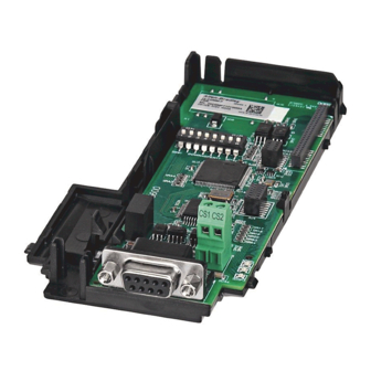
PowerFlex 525 DeviceNet Adapter
Catalog Number: 25-COMM-D
sales@aotewell.com
+86-755-8660-6182
Related Manuals for Allen-Bradley PowerFlex 525
Summary of Contents for Allen-Bradley PowerFlex 525
-
Page 1
Aotewell Ltd www.aotewell.com Industry Automation User Manual PowerFlex 525 DeviceNet Adapter Catalog Number: 25-COMM-D HongKong|UK|China sales@aotewell.com +86-755-8660-6182… -
Page 2: Important User Information
Identifies information that is critical for successful application and understanding of the product. Allen-Bradley, Rockwell Automation, Rockwell Software, PowerFlex, Studio 5000 and Connected Components Workbench are trademarks of Rockwell Automation, Inc. Trademarks not belonging to Rockwell Automation are property of their respective companies.
-
Page 3: Table Of Contents
Aotewell Ltd www.aotewell.com Industry Automation Table of Contents Important User Information ……..2 Preface Overview Recommended Documentation .
-
Page 4
Aotewell Ltd www.aotewell.com Industry Automation Table of Contents Understanding the I/O Image ……..48 Using Logic Command/Status . -
Page 5
Logic Status Word ……….128 PowerFlex 525 Drives… -
Page 6
Aotewell Ltd www.aotewell.com Industry Automation Table of Contents Notes: Rockwell Automation Publication 520COM-UM002A-EN-E — April 2013 HongKong|UK|China sales@aotewell.com +86-755-8660-6182… -
Page 7: Preface
DNET-UM004 DeviceNet Media Design Installation Guide DNET-UM072 DeviceNet Starter Kit User Manual DNET-UM003 PowerFlex®520-Series Drives PowerFlex 525 Adjustable Frequency AC Drive User Manual 520-UM001 RSLinx® Classic RSLinx Classic Getting Results Guide LINX-GR001 RSNetWorx for DeviceNet Getting Results with RSNetWorx for DeviceNet DNET-GR001 RSLogix™…
-
Page 8
Aotewell Ltd www.aotewell.com Industry Automation Preface Overview • RSLinx Classic (version 2.51), RSNetWorx for DeviceNet (version 21), and RSLogix 5000 (version 20) were used for the screen captures in this manual. Different versions of the software may differ in appearance and procedures. -
Page 9: Components
Industry Automation Chapter Getting Started The DeviceNet adapter is a communication option intended for installation into a PowerFlex 525 drive. The Multi-Drive feature (Chapter 7) also provides a means for other supported PowerFlex drives and DSI Hosts to connect to a DeviceNet network.
-
Page 10: Features
Getting Started Features The features of the DeviceNet adapter include: • Mounting onto a PowerFlex 525 Control Module back cover for installation into the drive. It receives the required power from the drive and from the DeviceNet network. • Switches to set a node address and network data rate before applying power to the PowerFlex drive.
-
Page 11: Compatible Products
Parameters icon in the tool bar. Compatible Products At the time of publication, the DeviceNet adapter is compatible with Allen- Bradley PowerFlex 525 drives. Required Equipment Equipment Shipped with the Drive When you unpack the adapter, verify that the package includes:…
-
Page 12: Safety Precautions
Aotewell Ltd www.aotewell.com Industry Automation Chapter 1 Getting Started Safety Precautions Please read the following safety precautions carefully. ATTENTION: Risk of injury or death exists. The PowerFlex drive may contain high voltages that can cause injury or death. Remove all power from the PowerFlex drive, and then verify power has been removed before installing or removing an adapter.
-
Page 13: Quick Start
Step Action See… Review the safety precautions for the adapter. Throughout this manual Verify that the PowerFlex drive is properly installed. PowerFlex 525 Adjustable Frequency AC Drive User Manual (publication 520-UM001) Commission the adapter. Chapter Installing the Adapter Set a unique node address and the appropriate data rate using the switches on the adapter.
-
Page 14
Aotewell Ltd www.aotewell.com Industry Automation Chapter 1 Getting Started Notes: Rockwell Automation Publication 520COM-UM002A-EN-E — April 2013 HongKong|UK|China sales@aotewell.com +86-755-8660-6182… -
Page 15: Preparing For An Installation
Aotewell Ltd www.aotewell.com Industry Automation Chapter Installing the Adapter Chapter 2 provides instructions for installing the DeviceNet adapter in a PowerFlex 525 drive. Topic Page Preparing for an Installation Commissioning the Adapter Connecting the Adapter to the Drive Connecting the Adapter to the Network…
-
Page 16
Aotewell Ltd www.aotewell.com Industry Automation Chapter 2 Installing the Adapter Setting the Node Address and Data Rate Using the DIP Switches Switch Description Default Least Significant Bit (LSB) of Node Address 1 Node 63 Bit 1 of Node Address Bit 2 of Node Address Bit 3 of Node Address Bit 4 of Node Address Most Significant Bit (MSB) of Node Address… -
Page 17: Connecting The Adapter To The Drive
Aotewell Ltd www.aotewell.com Industry Automation Installing the Adapter Chapter 2 Data Rate Switch Settings (UP = ON = 1) Switch Setting Data Rate SW 7 SW 8 125 kbps 250 kbps 500 kbps Autobaud If all switches are in the OFF position (all 0’s), then the Node Address and Data IMPORTANT Rate are determined by parameter settings (Device parameters 07 [Net Addr Cfg] and 09 [Net Rate Cfg]).
-
Page 18
Aotewell Ltd www.aotewell.com Industry Automation Chapter 2 Installing the Adapter b. Press down and slide out the top cover of the control module to unlock it from the power module. c. Hold the sides and top of the control module firmly, then pull out to separate it from the power module. -
Page 19: Connecting The Adapter To The Network
Aotewell Ltd www.aotewell.com Industry Automation Installing the Adapter Chapter 2 5. Align the Communication card-Drive header on the adapter with the interface connector. Then, press down firmly around the adapter. The adapter snaps into the back of the control module. The CS1/CS2 terminals on the adapter provide a clean ground for the IMPORTANT communication bus cable shields.
-
Page 20: Applying Power
Aotewell Ltd www.aotewell.com Industry Automation Chapter 2 Installing the Adapter 4. Connect the 5-pin linear plug to the DeviceNet cable. White Bare Blue Black Terminal Color Signal Function Power Supply White CAN_H Signal High Bare SHIELD Shield Blue CAN_L Signal Low Black Common A 5-pin linear plug is shipped with the adapter.
-
Page 21
8, Troubleshooting. Configuring/Verifying Key Drive Parameters The PowerFlex 525 drive can be separately configured for the control and Reference functions in various combinations. For example, you could set the drive to have its control come from a peripheral or terminal block with the Reference coming from the network. -
Page 22
2. Set the value of Host parameter P047 [Speed Reference1] to 4 “Network Opt”. The PowerFlex 525 drive supports up to three control functions and three Reference functions. For more information on how to set different combinations of the control and Reference functions, see the PowerFlex 525 drive user manual, publication 520-UM001. -
Page 23: Configuration Tools
Aotewell Ltd www.aotewell.com Industry Automation Chapter Configuring the Adapter Chapter 3 provides instructions and information for setting the parameters to configure the DeviceNet adapter. Topic Page Configuration Tools Using the Drive Keypad Interface to Access Parameters Using the PowerFlex 4-Class HIM to Access Parameters Setting the Node Address Setting the Data Rate Setting the I/O Configuration…
-
Page 24
Aotewell Ltd www.aotewell.com Industry Automation Chapter 3 Configuring the Adapter Step Key(s) Example Display 1. When power is applied, the last user-selected Basic Display Group parameter number is briefly HERTZ displayed with flashing characters. The display then defaults to that parameter’s current value. (Example shows the value of b001 [Output Freq] with the drive stopped.) 2. -
Page 25: Using The Powerflex 4-Class Him To Access Parameters
3. Select DSI Device in the DSEL tab if it is not DSI Devices already selected using the Up Arrow or Down Arrow. PowerFlex 525 Press Enter to select DSI Device. 25-COMM-D 4. Press the Up Arrow or Down Arrow to scroll DSI Devices to 25-COMM.
-
Page 26: Setting The Data Rate
2 “Drive 0-2” 3 “Drive 0-3” 4 “Drive 0-4” Drive 0 is the PowerFlex 525 with the 25-COMM-D adapter installed. Drive 1 through 4 are other PowerFlex drives that daisy-chain to the RJ45 (RS-485) port on Drive 0. See Chapter Using Multi-Drive Mode further instructions.
-
Page 27
Aotewell Ltd www.aotewell.com Industry Automation Configuring the Adapter Chapter 3 Configuring a Master-Slave Hierarchy The controller I/O image can have anywhere from zero to eight (four In and four Out) additional 16-bit parameters called Datalinks. They are configured using Host parameters C161 [Opt Data In 1] through C164 [Opt Data In 4], and C165 [Opt Data Out 1] through C168 [Opt Data Out 4]. -
Page 28: Selecting Cos, Cyclic, Or Polled I/O
Aotewell Ltd www.aotewell.com Industry Automation Chapter 3 Configuring the Adapter peripheral send values to the network. To configure these parameters, set them to the parameter number you wish to read over the network. The following steps are required to enable Datalinks to read data: 1.
-
Page 29: Setting A Fault Action
Aotewell Ltd www.aotewell.com Industry Automation Configuring the Adapter Chapter 3 Setting a Fault Action By default, when communications are disrupted (the network cable is disconnected) and/or the scanner is idle, the drive responds by faulting if it is using I/O from the network. You can configure a different response to: •…
-
Page 30: Resetting The Adapter
Aotewell Ltd www.aotewell.com Industry Automation Chapter 3 Configuring the Adapter Resetting the Adapter Changes to switch settings on some adapter parameters require that you reset the adapter before the new settings take effect. You can reset the adapter by cycling power to the drive or by using Device parameter 14 [Reset Module].
-
Page 31: Viewing The Adapter Status Using Parameters
When updating firmware through a direct USB connection from a computer to a drive, you will use the USB utility application. When updating firmware over the network, you can use the Allen-Bradley ControlFLASH software tool. Rockwell Automation Publication 520COM-UM002A-EN-E — April 2013 HongKong|UK|China sales@aotewell.com…
-
Page 32
Aotewell Ltd www.aotewell.com Industry Automation Chapter 3 Configuring the Adapter To obtain a firmware update for this adapter, go to http://www.ab.com/support/ abdrives/webupdate. This site contains all firmware update files and associated Release Notes that describe the following items: • Firmware update enhancements and anomalies •… -
Page 33: Using Rslinx Classic
Industry Automation Chapter Configuring the I/O This chapter provides instructions on how to configure a Rockwell Automation CompactLogix controller to communicate with the adapter and connected PowerFlex 525 drive. Topic Page Using RSLinx Classic CompactLogix Example Using RSLinx Classic RSLinx Classic, in all its variations (Lite, Gateway, OEM, etc.), is used to provide…
-
Page 34: Compactlogix Example
Command/Status, Reference/Feedback, and eight Datalinks (four to read and four to write) over the network. IP Address 192.168.1.3 Node 1 1769-L36ERM CompactLogix controller PowerFlex 525 drive with 25-COMM-D with embedded EtherNet/IP bridge DeviceNet adapter (Frame A shown) Ethernet switch 00:00:BC:2E:69:F6…
-
Page 35
Aotewell Ltd www.aotewell.com Industry Automation Configuring the I/O Chapter 4 1. Start RSLogix 5000/Logix Designer. The application window appears. Select File > New to display the New Controller window. Select the appropriate choices for the fields in the window to match your application. -
Page 36
Aotewell Ltd www.aotewell.com Industry Automation Chapter 4 Configuring the I/O Adding the Scanner to the I/O Configuration To establish communication between the controller and adapter over the network, you must add the scanner to the I/O configuration. 1. In the treeview, right-click the icon under the I/O Configuration folder and choose New Module.. -
Page 37
Aotewell Ltd www.aotewell.com Industry Automation Configuring the I/O Chapter 4 7. Edit the following: Setting Name A name to identify the scanner. Description Optional – description of the scanner. Slot The slot of the DeviceNet scanner in the rack. Revision The minor revision of the firmware in the scanner. -
Page 38
Aotewell Ltd www.aotewell.com Industry Automation Chapter 4 Configuring the I/O Using RSNetWorx for DeviceNet Software to Configure and Save the I/O Configuration to the Scanner After adding the scanner to the I/O configuration, you must configure and save the I/O to the scanner. 1. -
Page 39
If the icon for the drive (for this example, PowerFlex 525) on the network appears as Unrecognized Device, use RSNetWorx for DeviceNet software to create the PowerFlex 520-series drive EDS file. -
Page 40
3. In the Keyword entry field, enter the type of PowerFlex 520-series drive (for this example, PowerFlex 525), noting that this field is space sensitive. 4. Click Search. Due to the large number of EDS files, this search may take seconds or up to several minutes. -
Page 41
Aotewell Ltd www.aotewell.com Industry Automation Configuring the I/O Chapter 4 9. In the graph view window, right-click the 1769-SDN icon and choose Properties to display its properties dialog box. 10. Click the Module tab to display the Scanner Configuration dialog box. 11. -
Page 42
EDS file. 15. For this example, uncheck the Automap on Add. 16. Select the PowerFlex 525 drive in the Available Devices box and click to move it to the scanlist window. Setting Node Active Activates/deactivates the scanlist in the 1769-SDN scanner for the selected device. -
Page 43
Aotewell Ltd www.aotewell.com Industry Automation Configuring the I/O Chapter 4 b. Enter the number of bytes that are required for your I/O in the Input Size and Output Size boxes. For the example in this manual, all four [Opt DL Out 1…4] and all four [Opt DL In 1…4] are used, resulting in an Input size of “12”… -
Page 44
Aotewell Ltd www.aotewell.com Industry Automation Chapter 4 Configuring the I/O If a Scanner Configuration dialog box appears, click Yes to continue. The Edit I/O Parameters dialog box closes and then the 1769-SDN Scanlist tab dialog box reappears. 20. Click the Input tab to display the input registers for the 1769-SDN scanner. -
Page 45
Aotewell Ltd www.aotewell.com Industry Automation Configuring the I/O Chapter 4 If the Scanner Configuration dialog box appears asking to download these settings to the 1769-SDN scanner, click Yes. 25. From the File menu, choose Save. If this is the first time you saved the project, the Save As dialog box appears. a. -
Page 46
Aotewell Ltd www.aotewell.com Industry Automation Chapter 4 Configuring the I/O 1. From the Communications menu in the RSLogix 5000/Logix Designer dialog box, choose Download. The Download dialog box appears. If a message box reports that RSLogix 5000/Logix Designer software is unable to go online, find your controller in the Who Active dialog box. -
Page 47: About I/O Messaging
Industry Automation Chapter Using the I/O This chapter provides information and examples that explain how to control, configure, and monitor a PowerFlex 525 drive using the configured I/O. Topic Page About I/O Messaging Understanding the I/O Image Using Logic Command/Status…
-
Page 48: Understanding The I/O Image
Datalink 4 Datalink 4 Single drive mode is the typical configuration, where one node consists of a PowerFlex 525 drive with a 25-COMM-D adapter. For Multi-Drive mode, where one node can consist of up to 5 drives, see Chapter Using Multi-Drive Mode.
-
Page 49: Using Datalinks
Explicit Message. When enabled, each Datalink occupies one 16-bit word in a ControlLogix, CompactLogix, or MicroLogix controller. The following rules apply when using PowerFlex 525 drive Datalinks: • Datalinks can not be used with Multi-drive mode. • The target of a Datalink can be any appropriate Host parameter. For example, Host parameter P041 [Accel Time 1] can be the target of the DeviceNet adapter installed in the drive.
-
Page 50: Example Ladder Logic Program
Thus, use Datalinks when you need to change a value of a parameter frequently. Datalinks for PowerFlex 525 drive peripherals (embedded EtherNet/IP adapter and option modules such as a communication module) are locked when the peripheral has an I/O connection with a controller.
-
Page 51: Compactlogix Example
C168 [Opt Data Out 4] Points to drive parameter A410 [Preset Freq 0] The PowerFlex 525 drive supports up to three control functions and three Reference functions. There are several parameters in the drive that will override the start source and speed reference command if enabled. For details on these parameters, see the PowerFlex 525 drive’s user manual, publication…
-
Page 52
Aotewell Ltd www.aotewell.com Industry Automation Chapter 5 Using the I/O Program Tags In our example program, we will create 16-bit INT (integer) arrays for program tags and use “Copy” instructions to move this data to and from the 32-bit DINT (double integer) 1769-SDN scanner I/O tags. -
Page 53
Aotewell Ltd www.aotewell.com Industry Automation Using the I/O Chapter 5 Compact Logix Example Ladder Logic Program Using a Drive Generic Profile for Logic Command/ Reference Command Word DriveCommandStop DriveOutputImage[0].0 Command Word DriveCommandStart DriveOutputImage[0].1 Command Word DriveCommandJog DriveOutputImage[0].2 Command Word DriveCommandClearFaults DriveOutputImage[0].3 Command Word DriveCommandForward… -
Page 54
Aotewell Ltd www.aotewell.com Industry Automation Chapter 5 Using the I/O CompactLogix Controller Example Datalinks for Ladder Logic Program Using a Drive Generic Profile Rockwell Automation Publication 520COM-UM002A-EN-E — April 2013 HongKong|UK|China sales@aotewell.com +86-755-8660-6182… -
Page 55: About Explicit Messaging
PowerFlex 525 drives have explicit messaging limitations. See Explicit IMPORTANT Messaging Class Code Compatibility with PowerFlex 525 Drives on page 55 more information. Explicit Messaging Class Code Compatibility with PowerFlex 525 Drives DeviceNet Object Class Code…
-
Page 56: Performing Explicit Messaging
Aotewell Ltd www.aotewell.com Industry Automation Chapter 6 Using Explicit Messaging Performing Explicit There are five basic events in the Explicit Messaging process. The details of each step will vary depending on the type of controller being used. See the Messaging documentation for your controller.
-
Page 57
A Get Attribute Single message is used to read a single parameter. This read message example reads the value of the 16-bit parameter b003 [Output Current] in a PowerFlex 525 drive. Example Controller Tags to Read a Single Parameter Operation… -
Page 58: Chapter 7
DeviceNet node number of the drive (for this example, “1”). (3) See Explicit Messaging Class Code Compatibility with PowerFlex 525 Drives on page 55 for limitations of PowerFlex 525 drives when using DPI Parameter Object Class code 0x93 for explicit messaging.
-
Page 59: Chapter 7
DeviceNet node number of the drive (for this example, “1”). (4) See Explicit Messaging Class Code Compatibility with PowerFlex 525 Drives on page 55 for limitations of PowerFlex 525 drives when using DPI Parameter Object Class code 0x93 for explicit messaging.
-
Page 60
Message, a parameter number with Bit 15 set indicates that the associated parameter value field contains an error code (parameter number in response data will be negative). The PowerFlex 525 Adjustable Frequency AC Drive User Manual, publication 520-UM001 lists the data type for each parameter. -
Page 61
Aotewell Ltd www.aotewell.com Industry Automation Using Explicit Messaging Chapter 6 Data Structures for Scattered Read Messages Request (Source Data) Response (Destination Data) INT 0 Parameter Number INT 0 Parameter Number Parameter Value Parameter Number Parameter Number Parameter Value Parameter Number Parameter Number Parameter Value Parameter Number… -
Page 62
Aotewell Ltd www.aotewell.com Industry Automation Chapter 6 Using Explicit Messaging Data Structures for Scattered Write Messages Request (Source Data) Response (Destination Data) INT 0 Parameter Number INT 0 Parameter Number Parameter Value Parameter Number Parameter Number Parameter Value Parameter Number Parameter Number Parameter Value Parameter Number… -
Page 63
A Scattered Read message is used to read the values of multiple parameters. This read message example reads the values of these five 16-bit parameters in a PowerFlex 525 drive: • Host parameter b001[Output Freq] • Host parameter b003 [Output Current] •… -
Page 64
DeviceNet node number of the drive (for this example, “1”). (3) See Explicit Messaging Class Code Compatibility with PowerFlex 525 Drives on page 55 for limitations of PowerFlex 525 drives when using DPI Parameter Object Class code 0x93 for explicit messaging. -
Page 65
Scattered Read Response Converted Data on page 65 shows the parameter values. Example Scattered Read Response Converted Data In this message example, the Host parameters have the following values: PowerFlex 525 Drive Parameters Read Value b001 [Output Freq] 50.00 Hz b003 [Output Current] 0.01 Amp (No load) -
Page 66
Aotewell Ltd www.aotewell.com Industry Automation Chapter 6 Using Explicit Messaging Example Controller Tags to Write Multiple Parameters Operation Controller Tags for Scattered Write Message Data Types Execute_Scattered_Write_Message BOOL Scattered_Write_Message MESSAGE Example Ladder Logic to Write Multiple Parameters Execute_Scattered_Write_Message Message Message Control Scattered_Write_Message If you need to make frequent parameter changes using Explicit Messages, set IMPORTANT… -
Page 67
DeviceNet node number of the drive (for this example, “1”). (4) See Explicit Messaging Class Code Compatibility with PowerFlex 525 Drives on page 55 for limitations of PowerFlex 525 drives when using DPI Parameter Object Class code 0x93 for explicit messaging. -
Page 68
Aotewell Ltd www.aotewell.com Industry Automation Chapter 6 Using Explicit Messaging Example Scattered Write Response Data Rockwell Automation Publication 520COM-UM002A-EN-E — April 2013 HongKong|UK|China sales@aotewell.com +86-755-8660-6182… -
Page 69: Single-Drive Mode Vs. Multi-Drive Mode
Single-drive mode is a typical network installation, where a single DeviceNet node consists of a single drive with a 25-COMM-D DeviceNet adapter. Drive Mode Single-Drive Mode Example for Network One drive per node PowerFlex 525 PowerFlex 525 PowerFlex 525 with 25-COMM-D with 25-COMM-D…
-
Page 70
70). The first drive must be a PowerFlex 525 drive. The remaining drives can be any PowerFlex drive which supports Multi-drive. For the examples in the chapter, we will use the PowerFlex 525 as a Master IMPORTANT drive with four daisy-chained PowerFlex 4M drives. -
Page 71: System Wiring
(1203-USB). DSI Splitter cables cannot be used to add a second connection for a peripheral device. System Wiring To daisy-chain the drives of the PowerFlex 525, the AK-U0-RJ45-TB2P terminal block connector can be used for easy installation. The wiring diagram for using AK-U0-RJ45-TB2P terminal block connectors is shown below.
-
Page 72: Configuring The Rs-485 Network
Aotewell Ltd www.aotewell.com Industry Automation Chapter 7 Using Multi-Drive Mode Multi-Drive Example of I/O Image DeviceNet Controller Scanner Adapter Word and I/O Word 0 Logic Command Drive 0 PowerFlex Drive 0 Word 1 Reference Word 2 Logic Command Drive 1 PowerFlex Drive 1 Word 3 Reference…
-
Page 73: Multi-Drive Ladder Logic Program Example
Action(s). On the DeviceNet side, Device parameters 06 [Comm Flt Actn] and 07 [Idle Flt Actn] in the DeviceNet adapter determine the action taken for ALL of the drives on the Multi-drive node. The following Multi-drive parameters must be set in the master PowerFlex 525 drive: Parameter Configuration for Multi-Drive Mode…
-
Page 74: Compactlogix Example Using Generic Profile
PowerFlex 4M drive parameter P109 [Accel Time 1] for both so you can see (read) the change after a write is performed. Drive 0 (PowerFlex 525) Settings for the Example Program • Parameter C169 [MultiDrv Sel] is set to 1 “Network Opt”.
-
Page 75
Aotewell Ltd www.aotewell.com Industry Automation Using Multi-Drive Mode Chapter 7 The following Tags are used for Drive 0: Tag Name Type Description Drive_0_Command_Stop BOOL Logic Command bit 0 (STOP) Drive_0_Command_Start BOOL Logic Command bit 1 (START) Drive_0_Command_Jog BOOL Logic Command bit 2 (JOG) Drive_0_Command_Clear_Faults BOOL Logic Command bit 3 (CLEAR FAULTS) -
Page 76
CompactLogix DeviceNet Multi-drive example program with a PowerFlex 525 and DeviceNet adapter at node address 1. Four PowerFlex 4M drives are daisy-chained to the main PowerFlex 525 using their RJ45 ports (RS-485). In this mode, up to five PowerFlex drives can exist on one DeviceNet node. -
Page 77
Aotewell Ltd www.aotewell.com Industry Automation Using Multi-Drive Mode Chapter 7 Drive 0 Control Routine Drive 0 Control Subroutine This section takes the data from the input area and moves it to specific tags (Logic Status bits and Feedback) for use elsewhere in the ladder program. -
Page 78
Aotewell Ltd www.aotewell.com Industry Automation Chapter 7 Using Multi-Drive Mode Drive 1 Control Routine Drive 1 Control Subroutine This section takes the data from the input area and moves it to specific tags (Logic Status bits and Feedback) for use elsewhere in the ladder program. -
Page 79
Aotewell Ltd www.aotewell.com Industry Automation Using Multi-Drive Mode Chapter 7 Drive 2 Control Routine Drive 2 Control Subroutine This section takes the data from the input area and moves it to specific tags (Logic Status bits and Feedback) for use elsewhere in the ladder program. -
Page 80
Aotewell Ltd www.aotewell.com Industry Automation Chapter 7 Using Multi-Drive Mode Drive 3 Control Routine Drive 3 Control Subroutine This section takes the data from the input area and moves it to specific tags (Logic Status bits and Feedback) for use elsewhere in the ladder program. -
Page 81
Aotewell Ltd www.aotewell.com Industry Automation Using Multi-Drive Mode Chapter 7 Drive 4 Control Routine Drive 4 Control Subroutine This section takes the data from the input area and moves it to specific tags (Logic Status bits and Feedback) for use elsewhere in the ladder program. -
Page 82: Multi-Drive Mode Explicit Messaging
22528…23551 DeviceNet Adapter parameters 0…1023 For example, to access [Accel Time 1] (parameter P041 in PowerFlex 525 and P109 in PowerFlex 4M) in each of the drives, the following Instances would be used: • Drive 0 (PowerFlex 525) Instance = 17449 (17408 + 41) •…
-
Page 83: Additional Information
I/O connection is allowed on DeviceNet (i.e. before the drives can be controlled). • If the PowerFlex 525 drive with the 25-COMM-D DeviceNet adapter (Drive 0) is powered down, communications with the four daisy-chained drives (Drive 1 to Drive 4) are disrupted and the drives will take their corresponding Comm Loss Actions.
-
Page 84
Aotewell Ltd www.aotewell.com Industry Automation Chapter 7 Using Multi-Drive Mode • If any of the daisy-chained drives (Drive 1 to Drive 4) are powered down, the respective Input Image (Logic Status and Feedback) will be set to zero, and the NET A and PORT LEDs on the adapter will flash red. Status information will not indicate there is a fault at the node, and the I/O connection will not be dropped. -
Page 85: Understanding The Status Indicators
Viewing and Clearing Events Understanding the Status The DeviceNet adapter has three status indicators. They can be viewed on the adapter or through the drive cover. Indicators Status Indicators 25-COMM-D PowerFlex 525 Frame A shown ENET LINK EtherNet/IP Item Status Indicator Description Page…
-
Page 86: Port Status Indicator
Solid green The adapter is properly connected and is No Action. communicating with the drive. Orange Daisy-chained drives in Multi-drive mode Use Allen-Bradley PowerFlex 525/4/40’s for the daisy- are not all Allen-Bradley drives chained drives. (PowerFlex 525/4/40). MOD Status Indicator This red/green bicolor LED indicates the status of the option module as shown in the table below.
-
Page 87: Net A Status Indicator
Aotewell Ltd www.aotewell.com Industry Automation Troubleshooting Chapter 8 NET A Status Indicator This red/green bicolor LED indicates the status of the network connection as shown in the table below. Status Cause Corrective Actions The adapter and/or network is not powered •…
-
Page 88: Viewing And Clearing Events
Aotewell Ltd www.aotewell.com Industry Automation Chapter 8 Troubleshooting DeviceNet Adapter Diagnostic Parameters No. Name Description 15 Drv 3 Logic Cmd The present value of the Logic Command being transmitted to drive 3 (multi-drive mode) by this adapter. 16 Drv 3 Reference The present value of the Reference being transmitted to drive 3 (multi-drive mode) by this adapter.
-
Page 89
Many events in the event queue occur under normal operation. If you encounter unexpected communications problems, the events may help you or Allen-Bradley personnel troubleshoot the problem. The following events may appear in the… -
Page 90
Aotewell Ltd www.aotewell.com Industry Automation Chapter 8 Troubleshooting Adapter Events Code Event Description Net IO Close An I/O connection from the network to the adapter was closed. Net Idle Fault The adapter detected a network idle condition on the network and has performed the “Idle Flt”… -
Page 91: Communication
-10…50 °C (14…149 °F) Operating -40…85 °C (-40…185 °F) Storage Relative Humidity -5…95% noncondensing See the PowerFlex 525 Adjustable Frequency AC Drive User Manual, Regulatory Compliance publication 520-UM001 for regulatory compliance information. Rockwell Automation Publication 520COM-UM002A-EN-E — April 2013 HongKong|UK|China sales@aotewell.com…
-
Page 92
Aotewell Ltd www.aotewell.com Industry Automation Appendix A Specifications Notes: Rockwell Automation Publication 520COM-UM002A-EN-E — April 2013 HongKong|UK|China sales@aotewell.com +86-755-8660-6182… -
Page 93: Appendix B Device Parameters
Aotewell Ltd www.aotewell.com Industry Automation Appendix Adapter Parameters Appendix B provides information about the adapter parameters. Topic Page Device Parameters The adapter parameters are displayed in a Numbered List view order. Device Parameters Parameter Name and Description Details [MultiDrv Sel] Default: 0 = Disabled Sets the configuration of the drive that is in multi-drive mode.
-
Page 94
Aotewell Ltd www.aotewell.com Industry Automation Appendix B Adapter Parameters Parameter Name and Description Details [Net Addr Cfg] Default: Sets the network node address for the adapter when Device Minimum: parameter 06 [Net Addr Src] is set to 1 “Parameters”. Maximum: Type: Read/Write Reset Required:… -
Page 95
Aotewell Ltd www.aotewell.com Industry Automation Adapter Parameters Appendix B Parameter Name and Description Details [Comm Flt Action] Default: 0 = Fault Sets the action that the adapter and drive will take if the Values: 0 = Fault adapter detects that I/O communication has been disrupted. 1 = Stop This setting is effective only if I/O that controls the drive is 2 = Zero Data… -
Page 96
Aotewell Ltd www.aotewell.com Industry Automation Appendix B Adapter Parameters Parameter Name and Description Details [Flt Cfg Ref] Default: Sets the Reference data that is sent to the drive if any of the Minimum: -3.40282 x 10 following is true: Maximum: 3.40282 x 10 •… -
Page 97: Supported Data Types
Aotewell Ltd www.aotewell.com Industry Automation Appendix DeviceNet Objects Appendix C presents information about the DeviceNet objects that can be accessed using Explicit Messages. For information on the format of Explicit Messages and example ladder logic programs, see Chapter Using Explicit Messaging.
-
Page 98: Identity Object
Max Instance UINT Total number of instances Instance Attributes Attribute ID Access Rule Name Data Type Description Vendor ID UINT 1 = Allen-Bradley Device Type UINT Product Code UINT Number identifying product name and rating Revision: STRUCT of: Major USINT…
-
Page 99
Aotewell Ltd www.aotewell.com Industry Automation DeviceNet Objects Appendix C Attribute ID Access Rule Name Data Type Description Product Name SHORT_STRING Product name and rating Configuration WORD Checksum of configuration information Consistency Value Subminor UDINT Further revision information Revision Rockwell Automation Publication 520COM-UM001A-EN-E — April 2013 HongKong|UK|China sales@aotewell.com +86-755-8660-6182… -
Page 100: Assembly Object
Aotewell Ltd www.aotewell.com Industry Automation Appendix C DeviceNet Objects Assembly Object Class Code Hexadecimal Decimal 0x04 Services Implemented for: Service Code Class Instance Service Name 0x0E Get_Attribute_Single 0x10 Set_Attribute_Single Instances Instance Description Status Data – All I/O data being read from the DSI device (read-only) Command Data –…
-
Page 101: Connection Object
Aotewell Ltd www.aotewell.com Industry Automation DeviceNet Objects Appendix C Connection Object Class Code Hexadecimal Decimal 0x05 Services Implemented for: Service Code Class Instance Service Name 0x0E Get_Attribute_Single 0x10 Set_Attribute_Single (1) This service does not support class access. Instances Instance Description Master-Slave Explicit Message Connection Polled I/O Connection Change of State/Cyclic Connection…
-
Page 102
Aotewell Ltd www.aotewell.com Industry Automation Appendix C DeviceNet Objects Attribute ID Access Rule Name Data Type Description Produced Connection Array of UINT Byte stream which defines Path Application objects whose data is to be produced by this Connection object Consumed Path Length UINT Number of bytes of data in the consumed connection path… -
Page 103: Register Object
Aotewell Ltd www.aotewell.com Industry Automation DeviceNet Objects Appendix C Register Object Class Code Hexadecimal Decimal 0x07 Services Implemented for: Service Code Class Instance Service Name 0x0E Get_Attribute_Single 0x10 Set_Attribute_Single Instances (Single-Drive) Instance Description Status Image – All I/O data being read from the adapter (read-only) Command Image –…
-
Page 104
Aotewell Ltd www.aotewell.com Industry Automation Appendix C DeviceNet Objects Instance Description Logic Status (read-only) Reference (read/write) Feedback (read-only) (1) The mask command DWORD is set to the value of the first DWORD of the data where there are ones in the second DWORD of the data. -
Page 105
Aotewell Ltd www.aotewell.com Industry Automation DeviceNet Objects Appendix C Class Attributes Attribute ID Access Rule Description Read Revision Read Maximum Instance Read Number of Instance Read/Write Timeout Instance Attributes Attribute ID Access Rule Name Data Type Description Bad Flag BOOL If set to 1, then attribute 4 may contain invalid data. -
Page 106: Parameter Object
Aotewell Ltd www.aotewell.com Industry Automation Appendix C DeviceNet Objects Parameter Object Class Code Hexadecimal Decimal 0x0F Services Implemented for: Service Code Class Instance Service Name 0x01 Get_Attribute_All 0x05 Reset 0x0E Get_Atribute_Single 0x10 Set_Attribute_Single 0x4B Get_Enum_String Instances (Single-Drive) Instance Description Class Drive Parameter 1 Drive Parameter n n + 1…
-
Page 107
Aotewell Ltd www.aotewell.com Industry Automation DeviceNet Objects Appendix C Class Attributes Attribute ID Access Rule Name Data Type Description Revision UINT Max Instance UINT Number of parameters Parameter Class Descriptor WORD 0 = False, 1 = True Bit 0 = Supports parameter instances Bit 1 = Supports full attributes Bit 2 = Must do NVS save command Bit 3 = Parameters are stored in NVS… -
Page 108
Aotewell Ltd www.aotewell.com Industry Automation Appendix C DeviceNet Objects Attribute ID Access Rule Name Data Type Description Default Value Scaling UINT Multiplier Scaling UINT Divisor Scaling UINT Base Scaling UINT Offset Multiplier UINT Link Divisor UINT Link Base Link UINT Offset UINT Link… -
Page 109: Parameter Group Object
Aotewell Ltd www.aotewell.com Industry Automation DeviceNet Objects Appendix C Parameter Group Object This object is supported only in single-drive mode. IMPORTANT Class Code Hexadecimal Decimal 0x10 Services Implemented for: Service Code Class Instance Service Name 0x0E Get_Atribute_Single Instances Instance Description Class Drive Parameter 1 Drive Parameter n…
-
Page 110
Aotewell Ltd www.aotewell.com Industry Automation Appendix C DeviceNet Objects Instance Attributes Attribute ID Access Rule Name Data Type Description Group SHORT_STRI Group name Name String Link Path UINT Number of parameters in group. Size UINT Paramete r Number in Group UINT Paramete r Number… -
Page 111: Pccc Object
Aotewell Ltd www.aotewell.com Industry Automation DeviceNet Objects Appendix C PCCC Object Class Code Hexadecimal Decimal 0x67 Services Implemented for: Service Code Class Instance Service Name 0x4B Execute_PCCC 0x4C Execute_DH+ 0x4D Execute_Local_PCCC Instances Supports Instance 1. Class Attribute Not supported. Instance Attributes Not supported.
-
Page 112
Aotewell Ltd www.aotewell.com Industry Automation Appendix C DeviceNet Objects Message Structure for Execute_Local_PCCC Request Response Name Data Type Description Name Data Type Description USINT Command byte USINT Command byte USINT USINT Status byte TNSW UINT Transport word TNSW UINT Transport word. Same value as the request. USINT Function code. -
Page 113
Aotewell Ltd www.aotewell.com Industry Automation DeviceNet Objects Appendix C N-Files (Multi-Drive) N-File Description This N-file lets you read and write control I/O messages. You can write control I/O messages only when all of the following conditions are true: • The adapter is not receiving I/O from a scanner. For example, there is no scanner on the network, the scanner is in idle (program) mode, the scanner is faulted, or the adapter is not mapped to the scanner. -
Page 114: Dpi Device Object
Aotewell Ltd www.aotewell.com Industry Automation Appendix C DeviceNet Objects DPI Device Object Class Code Hexadecimal Decimal 0x92 Services Implemented for: Service Code Class Instance Service Name 0x0E Get_Attribute_Single 0x10 Set_Attribute_Single Instances The number of instances depends on the number of components in the device. The total number of components can be read in Instance 0, Class Attribute 4.
-
Page 115
USINT Identification of variations. Configuration Text STRING[16] Text identifying a variation of a family device. Brand Code UINT 0x0001 = Allen-Bradley NVS Checksum UINT Checksum of the Non-Volatile Storage in a device. Class Revision UINT 2 = DSI Character Set Code… -
Page 116
Aotewell Ltd www.aotewell.com Industry Automation Appendix C DeviceNet Objects Instance Attribute Attribute ID Access Rule Name Data Type Description Component Name STRING[32] Name of the component Component Firmware Revision STRUCT of: USINT Major Revision USINT Minor Revision Component Serial Number UDINT Value between 0x00000000 and 0xFFFFFFFF International Component Name… -
Page 117: Dpi Parameter Object
Aotewell Ltd www.aotewell.com Industry Automation DeviceNet Objects Appendix C DPI Parameter Object Class Code Hexadecimal Decimal 0x93 Instances The number of instances depends on the number of parameters in the device. The total number of parameters can be read in Instance 0, Attribute 0. Instances (Hex.) Instances (Dec.) Single-Drive Mode…
-
Page 118
Aotewell Ltd www.aotewell.com Industry Automation Appendix C DeviceNet Objects Instance Attribute Attribute ID Access Rule Name Data Type Description DSI Offline Read Full STRUCT of: BOOL[32] Descriptor CONTAINER Offline Minimum value CONTAINER Offline Maximum value CONTAINER Offline Default value STRING[16] Parameter name STRING[4] Offline parameter units… -
Page 119
Aotewell Ltd www.aotewell.com Industry Automation DeviceNet Objects Appendix C Attribute ID Access Rule Name Data Type Description International DSI Online Read Full Struct of: BOOL[32] Descriptor CONTAINER Parameter value CONTAINER Online minimum value CONTAINER Online maximum value CONTAINER Online default value UINT Next UINT… -
Page 120
Aotewell Ltd www.aotewell.com Industry Automation Appendix C DeviceNet Objects Descriptor Attributes Name Description Data Type (Bit 1) Right bit is least significant bit (0). 000 = USINT used as an array of Boolean Data Type (Bit 2) 001 = UINT used as an array of Boolean Data Type (Bit 3) 010 = USINT (8-bit integer) 011 = UINT (16-bit integer) -
Page 121
Aotewell Ltd www.aotewell.com Industry Automation DeviceNet Objects Appendix C Extended Descriptor Attributes Name Description Indirect Mode 0 = Analog (selects entire parameters) 1 = Digital (selects individual bits within parameters) Indirect Type 0 Analog input list (Instance 0xFFFF) Indirect Type 1 Digital input list (Instance 0xFFFE) Indirect Type 2 Feedback list (Instance 0xFFFD) -
Page 122
Aotewell Ltd www.aotewell.com Industry Automation Appendix C DeviceNet Objects Formulas for Converting Decimal Places Display Value = ((Internal Value + Offset) x Multiplier x Base) / (Divisor x 10 Decimal Places Internal Value = ((Display Value x Divisor x 10 ) / (Multiplier x Base)) — Offset Common Services Implemented for:… -
Page 123: Dpi Fault Object
Aotewell Ltd www.aotewell.com Industry Automation DeviceNet Objects Appendix C DPI Fault Object Class Code Hexadecimal Decimal 0x97 Products such as PowerFlex drives use this object for faults. Adapters use this object for events. Services Implemented for: Service Code Class Instance Service Name 0x0E Get_Attribute_Single…
-
Page 124
Aotewell Ltd www.aotewell.com Industry Automation Appendix C DeviceNet Objects Instance Attributes Attribute ID Access Rule Name Data Type Description Full/All Information STRUCT of UINT Fault code STRUCT of: Fault source USINT DSI port USINT DSI Device Object STRING[16] Fault text STRUCT of: Fault time stamp LWORD… -
Page 125: Dpi Diagnostic Object
Aotewell Ltd www.aotewell.com Industry Automation DeviceNet Objects Appendix C DPI Diagnostic Object Class Code Hexadecimal Decimal 0x99 Services Implemented for: Service Code Class Instance Service Name 0x0E Get_Attribute_Single 0x10 Set_Attribute_Single Instances The number of instances depends on the maximum number of diagnostic items supported by the device.
-
Page 126
Aotewell Ltd www.aotewell.com Industry Automation Appendix C DeviceNet Objects Instance Attribute Attribute ID Access Rule Name Data Type Description Full/All Information STRUCT of: BOOL[32] Descriptor (see page 120) CONTAINER Value CONTAINER Minimum value CONTAINER Maximum value CONTAINER Default value UINT Pad Word UINT Pad Word… -
Page 127: Logic Command Word
Logic Command/Status Words: PowerFlex 525 Drives Appendix D presents the definitions of the Logic Command and Logic Status words that are used for PowerFlex 525 drives. Logic Command Word Velocity Bit Definitions Comm Logic Command – C122 = 0 “Velocity”…
-
Page 128: Logic Status Word
Aotewell Ltd www.aotewell.com Industry Automation Appendix D Logic Command/Status Words: PowerFlex 525 Drives Position Bit Definitions Comm Logic Command – C122 = 1 “Position” Logic Bits 15 14 13 12 11 10 9 Command Description Normal Stop 0 = Not Normal Stop…
-
Page 129: Rockwell Automation Publication 520Com-Um002A-En-E — April
Aotewell Ltd www.aotewell.com Industry Automation Logic Command/Status Words: PowerFlex 525 Drives Appendix D Position Bit Definitions Comm Logic Status – C122 = 1 “Position” Logic Bits 15 14 13 12 11 10 9 Command Description Run Ready 0 = Not Ready to Run…
-
Page 130
Aotewell Ltd www.aotewell.com Industry Automation Appendix D Logic Command/Status Words: PowerFlex 525 Drives Notes: Rockwell Automation Publication 520COM-UM002A-EN-E — April 2013 HongKong|UK|China sales@aotewell.com +86-755-8660-6182… -
Page 131: Glossary
Industry Automation Glossary The following terms and abbreviations are used throughout this manual.For definitions of terms not listed here, see the Allen-Bradley Industrial Automation Glossary, publication AG-7.1. Adapter Devices such as drives, controllers, and computers usually require an adapter to provide a communication interface between them and a network such as DeviceNet.
-
Page 132: Glossary
All objects in a class are identical in form and behavior, but may contain different attribute values.’ ControlFLASH A free software tool used to electronically update the firmware of Allen-Bradley products and network communication adapters. ControlFLASH software is downloaded automatically when the firmware revision file for the product being updated is downloaded from the Allen-Bradley updates website to your computer.
-
Page 133: Glossary
Industry Automation Glossary Datalinks A Datalink is a type of pointer used by PowerFlex 525 drives to transfer data to and from the controller. Datalinks allow specified parameter value(s) to be accessed or changed without using explicit messages. When enabled, each 16-bit Datalink in a PowerFlex 525 drive consumes 4 bytes in the input image table and/ or 4 bytes in the output image table of the controller.
-
Page 134: Glossary
If the drive was running and using the Reference from the adapter, it will continue to run at the same Reference. Idle Action An idle action determines how the adapter and its PowerFlex 525 drive act when the controller is switched out of run mode.
-
Page 135: Glossary
Command from the scanner and then sends back the Logic Status of the connected PowerFlex drive. PowerFlex 525 Drives The Allen-Bradley PowerFlex 525 drives are part of the PowerFlex 520-Series of drives. Product/Consumer Network On producer/consumer networks, packets are identified by content rather than an explicit destination.
-
Page 136: Glossary
(for example, to convert 32-bit REAL parameter data to correctly write and read their values). Update The process of updating firmware in a device. The adapter can be updated using various Allen-Bradley software tools. See Updating the Adapter Firmware on page 31 for more information.
-
Page 137
Aotewell Ltd www.aotewell.com Industry Automation Index definition adapter adding to the scan list applying power data exchange commissioning Change of State (COS) components cyclic configuration tools polled connecting to the drive data rate connecting to the network definition definition setting with a parameter diagnostic parameters setting with the switches events… -
Page 138: Index
Aotewell Ltd www.aotewell.com Industry Automation Index setting the fault action list PCCC (Programmable Controller Communications Command) definition events object about polled calculating I/O byte sizes configuring the scanner configuring a scanner for definition configuring an adapter for mapping in the scanner definition setting the configuration producer/consumer network…
-
Page 139
Aotewell Ltd www.aotewell.com Industry Automation HongKong|UK|China sales@aotewell.com +86-755-8660-6182… -
Page 140: Rockwell Automation Support
Aotewell Ltd www.aotewell.com Industry Automation Rockwell Automation Support Rockwell Automation provides technical information on the Web to assist you in using its products. , you can find technical manuals, a knowledge base of FAQs, technical and http://www.rockwellautomation.com/support/ application notes, sample code and links to software service packs, and a MySupport feature that you can customize to make the best use of these tools.
(Ocr-Read Summary of Contents of some pages of the Allen-Bradley PowerFlex 525 Document (Main Content), UPD: 09 September 2023)
-
30, 30 Rockwell Automation Publication 520-TD001B-EN-E — June 2013 PowerFlex 525 AC Drive Specifications Accessories and Dimensions (1) The resistors listed in this tables are rated for 5% duty cycle. (2) Use of Rockwell Automation resistors is always recommended. The resistors listed have been carefully selected for optimizing performance in a variety of applications. Alternative resistors may be used, h…
-
20, Allen-Bradley PowerFlex 525 20 Rockwell Automation Publication 520-TD001B-EN-E — June 2013 PowerFlex 525 AC Drive Specifications Shield Termination — SHLD Either of the safety ground terminals located on the power terminal block provides a grounding point for the motor cable shield. The motor cable shield connected to one of these terminals (drive end) should also be connected to the motor frame (motor end). Use a shield terminating or EMI …
-
26, 26 Rockwell Automation Publication 520-TD001B-EN-E — June 2013 PowerFlex 525 AC Drive Specifications 100…120V 1-Phase Input Protection Devices – Frames A…B 200…240V 1-Phase Input Protection Devices – Frames A…B (1) The AIC ratings of the Bulletin 140M Motor Protector Circuit Breakers may vary. See Bulletin 140M Motor Protection Circuit Breakers Application Ratings. (2) Manual Self-Protected (Type E) Combination Motor Controller, UL listed …
-
3, Rockwell Automation Publication 520-TD001B-EN-E — June 2013 3 PowerFlex 525 AC Drive Specifications PowerFlex 525 Advanced Features Control Performance • Variety of motor control options, including: • Volts per hertz • Sensorless Vector Control (SVC) • Closed loop velocity vector control • Variety of Positioning Control, including: • PointStop™ stops motor load in a consistent position without encoder feedback • Closed loop feedb…
-
4, 4 Rockwell Automation Publication 520-TD001B-EN-E — June 2013 PowerFlex 525 AC Drive Specifications Communications •Embedded EtherNet/IP™ port allows easy configuration, control, and collection of drive data over the network. •Dual port EtherNet/IP option card supports Device Level Ring (DLR) topologies, providing fault-tolerant connectivity for optimum drive availability. • Integral RS485/DSI communications enable the drives to be used in a multi-drop network configuration. • Option…
-
5, Rockwell Automation Publication 520-TD001B-EN-E — June 2013 5 PowerFlex 525 AC Drive Specifications Improved Ride Through Operation Down to 1/2 Line Voltage The PowerFlex 525 drive allows for the selection of 1/2 DC Bus operation, for use in critical applications where continued drive output is desired even in the event of brown out or low voltage conditions. The PowerFlex 525 drive also supports enhanced inertia ride th…
-
36, 36 Rockwell Automation Publication 520-TD001B-EN-E — June 2013 PowerFlex 525 AC Drive Specifications (1) Normal Duty and Heavy Duty ratings for 15 HP / 11 kW and below are identical. (2) Catalog numbers listed are for 3% impedance. 5% impedance reactor types are also available. See publication 1321-TD001 . (3) Input line reactors were sized based on the NEC fundamental motor amps. Output line reactors were s…
-
41, Rockwell Automation Publication 520-TD001B-EN-E — June 2013 41 PowerFlex 525 AC Drive Specifications Connection Examples Example 1 – Safe-Torque-Off Connection with Coast-to-Stop Action, SIL 2/PL d (1) Safety relay and PowerFlex 525 must be installed in the same enclosure. (2) In some situations, a safety relay is not required if both the switch and PowerFlex 525 are installed in the same enclosure. Stop Start A1 S21 S11 S52 41 13 23 33 A2 24V DC common +24V DC S22 S14 S34 42 14 24 34 MSR…
-
25, Rockwell Automation Publication 520-TD001B-EN-E — June 2013 25 PowerFlex 525 AC Drive Specifications Fuses and Circuit Breaker Ratings The PowerFlex 525 drive does not provide branch short circuit protection. This product should be installed with either input fuses or an input circuit breaker. National and local industrial safety regulations and/or electrical codes may determine additional requirements for these installations. The tables…
-
7, Rockwell Automation Publication 520-TD001B-EN-E — June 2013 7 PowerFlex 525 AC Drive Specifications PowerFlex 525 Drive Family Frame A Frame B Frame C Frame D Frame E
… -
6, Allen-Bradley PowerFlex 525 6 Rockwell Automation Publication 520-TD001B-EN-E — June 2013 PowerFlex 525 AC Drive Specifications Communications and Software Versatile Programming and Network Solutions • PowerFlex 525 is compatible with any device that acts as a RTU Master and supports standard 03 and 06 RTU commands. • A network can be configured using PowerFlex 525 drives for high performance and flexible configuration capabilities. • EtherNet/IP standard (Dual port option available) •…
-
22, 22 Rockwell Automation Publication 520-TD001B-EN-E — June 2013 PowerFlex 525 AC Drive Specifications Reflected Wave Protection The drive should be installed as close to the motor as possible. Installations with long motor cables may require the addition of external devices to limit voltage reflections at the motor (reflected wave phenomena). Refer to Reflected Wave in “Wiring and Grounding Guide, (PWM) AC Drives,” publication DRIVES-IN001 . T…
-
24, 24 Rockwell Automation Publication 520-TD001B-EN-E — June 2013 PowerFlex 525 AC Drive Specifications Maximum Control Wire Recommendation Do not exceed control wiring length of 30 m (100 ft). Control signal cable length is highly dependent on electrical environment and installation practices. To improve noise immunity, the I/O terminal block Common may be connected to ground terminal/protective earth. If using the RS485 (DSI) port, I/O T…
-
1, Technical Data PowerFlex 525 AC Drive Specifications Original Instructions Topic Page Product Overview 2 Catalog Number Explanation 8 Technical Specifications 9 Environmental Specifications 11 Certifications 12 Dimensions and Weights 13 Design Considerations 15 Fuses and Circuit Breaker Ratings 25 Accessories and Dimensions 30 Safe-Torque-Off Function 39 Additional Resources 43
… -
29, 29 Rockwell Automation Publication 520-TD001B-EN-E — June 2013 PowerFlex 525 AC Drive Specifications 525…600V 3-Phase Input Protection Devices – Frames A…E (1) Normal and Heavy duty ratings are available for drives above 15 HP / 11 kW. (2) The AIC ratings of the Bulletin 140M Motor Protector Circuit Breakers may vary. See Bulletin 140M Motor Protection Circuit Breakers Application Ratings . (3) Manual Self-Protected (Type E) Combination Motor Controller, UL listed for…
-
28, Allen-Bradley PowerFlex 525 Rockwell Automation Publication 520-TD001B-EN-E — June 2013 28 PowerFlex 525 AC Drive Specifications 380…480V 3-Phase Input Protection Devices – Frames A…E (1) Normal and Heavy duty ratings are available for drives above 15 HP / 11 kW. (2) The AIC ratings of the Bulletin 140M Motor Protector Circuit Breakers may vary. See Bulletin 140M Motor Protection Circuit Breakers Application Ratings . (3) Manual Self-P…
-
44, Allen-Bradley, Rockwell Software, Rockwell Automation, PowerFlex, Connected Components Workbench, Studio 5000, DriveTools SP, AppView, CustomView, MainsFree Programming, and P ointStop are trademarks of Rockwell Automation, Inc. Trademarks not belonging to Rockwell Automation are property of their respective companies. Publication 520-TD001B-EN-E — June 2013 Supersedes Publication 520-TD001A-EN-E – February 2013 Copyright © 201…
|
|
Related Devices:
|
Types of Manuals:
The main types of Allen-Bradley PowerFlex 525 instructions:
- User guide — rules of useing and characteristics
- Service manual — repair, diagnostics, maintenance
- Operation manual — description of the main functions of equipment
Adapter, Controller, DC Drives, Media Converter Instructions by Allen-Bradley:
-
Hama Nano Bluetooth USB Adapter
FDGBERUSPLPIHTRFINNLCZDKSKSNBGOperating InstructionsBedienungsanleitungMode d‘emploiInstrucciones de usoРуководство по эксплуатацииIstruzioni per l‘usoGebruiksaanwijzingInstrukcja obsługiHasználati útmutatóNávod kpoužitíNávod na použitieManual de instruçõesKullanma kılavuzuBruks …
Nano Bluetooth USB Adapter Adapter, 58
-
Canon CA-PS700
45x112x29mm(18x44x1.1in)Approx186g (65 oz)o-40°C(32-104OF)100-240VAC(50/60Hz)0.32A7.4VDC,2.0AWeight:RatedOutput:Dimensions:OperatingTemperatures:RatedInput:Please read thisguidebeforeusingtheequipment.•Thismanual explainshowtousethis equipmentforCanon’sdigital cameras.Pleasebesuretoread your camera’s manua …
CA-PS700 Adapter, 2
-
Vivo MOUNT-SG001A
VESA Adapter for Compatible Samsung MonitorsScan the QR code with your mobile device or follow the link for helpful videos and specifications related to this product.Instruction Manualhttps://vivo-us.com/products/mount-sg001aSKU: [email protected] www.vivo-us.com 309-278-5303 …
MOUNT-SG001A Adapter, 4
-
Digikeijs DR5039
DR5039 LocoNet B ‐> CDE Adapter www.digikeijs.com P 1 DR5039 HANDLEIDING / MANUAL BEDIENUNGSANLEITUNG / MANUEL V1.0 08‐2016 © Copyright 2005 – 2017. The Netherlands. All rights reserved. No informaon, …
DR5039 Adapter, 8
-
Renkforce RF-HSA-200
Inbetriebnahme und VerwendungWichtig:Je nach Ihrer Systemeinrichtung, Systemkonguration und Hardware-Verfügbarkeit unterstützt Ihre Gerät möglicherweise nicht alle Funktionen. Die Betriebsanzeige leuchtet bei eingeschaltetem Computer.Bei Aktivität leuchten die Lampen (rot/blau) auf.a) Microsoft Teams und Sk …
RF-HSA-200 Adapter, 4
-
Hama 00011572
0001157200011572-01.07Hama GmbH & Co KGPostfach 80 86651 Monheim/GermanyTel. +49 (0)9091/502-0 Fax + 49 (0) 90 91 / 5 02-2 [email protected] USB-AdapterVersion 1.200011572bda 04.01.2007 15:58 Uhr Seite 2 …
00011572 Adapter, 4
-
Paradyne 6511
99-16484PCorHubSuperLine IADLINEPHONE99-16410geprufteSicherheitRLR92997TMTUYPRODUCT SERVICEPhone FilterP/N 0802-3392-00Made in China / Fabriquè ChinaBel Fuse Inc. 1198ACCESSARYL.T.E. EQUIPMENTE100296SuperLine IAD Model 6511Quick InstallationDocument Number 6511-A2-GZ40-00September 1999Quick Installation Go to th …
6511 Adapter, 1
-
US Robotics USR5462
Wireless Starter Kit802.11g 54Mbps Router802.11g 54Mbps USB AdapterInstallation GuideGuide d’installationInstallationsanleitungGuida all’installazione rapidaGuía breve de instalaciónBeknopte installatiegidsR24.0496.00 …
USR5462 Wireless Router, 20
Documents: Allen-Bradley PowerFlex 525 Adapter PDF User Manuals and Service Instructions (8 Allen-Bradley PowerFlex 525 Manuals found in DataBase)
Allen-Bradley PowerFlex 525: List of Manuals
| # | Screen | Document Information | Share in Social |
|---|---|---|---|
| 1 |

|
Allen-Bradley PowerFlex 525 Quick start manual (36 pages) Allen-Bradley PowerFlex 525 Allen-Bradley PowerFlex 523 Quick Start Manual Adapter Media Converter Controller 36 |
|
| 2 |

|
Allen-Bradley PowerFlex 525 Application technique (24 pages) Allen-Bradley PowerFlex 525 24 |
|
| 3 |

|
Allen-Bradley PowerFlex 525 Installation instructions (2 pages) Allen-Bradley PowerFlex 525 Allen-Bradley PowerFlex 525 Installation Instructions Adapter Media Converter Controller 2 |
|
| 4 |

|
Allen-Bradley PowerFlex 525 Original instructions manual (48 pages) Allen-Bradley PowerFlex 525 Allen-Bradley PowerFlex 525 Original Instructions Manual Adapter Media Converter Controller 48 |
|
| 5 |

|
Allen-Bradley PowerFlex 525 Original instructions manual (44 pages) Allen-Bradley PowerFlex 525 Allen-Bradley PowerFlex 525 Original Instructions Manual Adapter Media Converter Controller 44 |
|
| 6 |

|
Allen-Bradley PowerFlex 525 Operation & user’s manual (228 pages) Allen-Bradley PowerFlex 525 228 |
|
| 7 |

|
Allen-Bradley PowerFlex 525 Operation & user’s manual (164 pages) Allen-Bradley PowerFlex 525 164 |
|
| 8 |

|
Allen-Bradley PowerFlex 525 Operation & user’s manual (140 pages) Allen-Bradley PowerFlex 525 140 |
Adapter Appliance:
More Products:
- SLC 500 1747-L20
- Compact GuardLogix 5370
- MP-Series
- Guard Master MSR22LM
- PowerFlex 20-COMM-D
- Bulletin 161 B Series
- 25-JBAA
- 842E-SIP*BA
- E3 Plus
Related Instructions for PowerFlex 525:
Categories of Allen-Bradley Devices:
Power Tool
Transducer
Marine Equipment
Network Cable
Cable Tester
Surge Protector
Adapter
Amplifier
Barcode Reader
Network Card
Controller
Network Hardware
Network Router
Power Supply
UPS