-
Contents
-
Table of Contents
-
Bookmarks
Quick Links
User Guide
Site Masterä
S331D
Cable and Antenna Analyzer
Anritsu Company
PN: 10580-00079
490 Jarvis Drive
Revision: K
Morgan Hill, CA 95037-2809
Published: April 2009
Copyright ã 2003-2009 Anritsu Co.
USA
Related Manuals for Anritsu Sire Master S331D
Summary of Contents for Anritsu Sire Master S331D
-
Page 1
User Guide Site Masterä S331D Cable and Antenna Analyzer Anritsu Company PN: 10580-00079 490 Jarvis Drive Revision: K Morgan Hill, CA 95037-2809 Published: April 2009 Copyright ã 2003-2009 Anritsu Co. -
Page 2
Anritsu Company. UPDATES Updates to this manual, if any, may be downloaded from the Anritsu Internet site at: http://www.us.anritsu.com Anritsu contact information can be accessed from the following Internet site:… -
Page 3
S331D, MS2711D… -
Page 4
“WEEE Directive”) in European Union. For Products placed on the EU market after August 13, 2005, please contact your local Anritsu representative at the end of the product’s useful life to arrange disposal in accordance with your initial contract and the local law. -
Page 5
ESD Precautions ……. 1-11 Anritsu Service Centers……1-11 Mode References . -
Page 6
Chapter 3 Getting Started Introduction ……..3-1 Power On Procedure . -
Page 7
Chapter 7 Handheld Software Tools Introduction ……..7-1 Features . -
Page 9: Introduction
Chapter 1 General Information Introduction This chapter provides a description, performance specifications, optional accessories, preventive maintenance, and calibration requirements for the Site Master™ model S331D. Throughout this manual, the term Site Master will refer to the S331D. Model Frequency Range S331D Cable and Antenna Analyzer Mode: 25 to 4000 MHz…
-
Page 10: Standard Accessories
Chapter 1 General Information Standard Accessories The Handheld Software Tools and Master Software Tools PC-based software programs provide a database record for storing measurement data. Software Tools can also convert the Site Master display to a Microsoft Windowsä workstation graphic. Measurements stored in the Site Master internal memory can be downloaded to the PC using the included null-modem serial cable.
-
Page 11: External Detectors
Chapter 1 General Information External Detectors The following Anritsu detectors can be used with the Site Master S331D when equipped with Option 5, Power Monitor. Frequency Input Model Impedance Return Loss Frequency Response Range Conn. ±0.2 dB, <1 GHz 5400-71N50 0.001 to 3 GHz…
-
Page 12: Optional Accessories
Chapter 1 General Information Optional Accessories Part Number Description Calibration Components ICN50B InstaCal™ Calibration Module, 2 MHz to 6.0 GHz, N(m), 50W OSLN50-1 Precision Open/Short/Load, DC to 6 GHz, 42 dB, 50W, N(m) OSLNF50-1 Precision Open/Short/Load, DC to 6 GHz, 42 dB, 50W, N(f) 22N50 Open/Short, DC to 18 GHz, N(m), 50W SM/PL-1…
-
Page 13
Chapter 1 General Information Test Port Cables, Armored 15NN50-1.5C Test Port Cable Armored, 1.5 meters, N(m)-N(m), 6 GHz, 15NN50-3.0C Test Port Cable Armored, 3.0 meters, N(m)-N(m), 6 GHz, 15NNF50-1.5C Test Port Cable Armored, 1.5 meters, N(m)-N(f), 6 GHz, 50W 15NNF50-3.0C Test Port Cable Armored, 3.0 meters, N(m)-N(f), 6 GHz, 50W Test Port Cables, Armored w/ Reinforced Grip 15RNFN50-1.5-R… -
Page 14
Attenuator, 30 dB, 50 Watt, DC to 8.5 GHz, N(m)-N(f) 3-1010-124 Attenuator, 40 dB, 100W, DC to 8.5 GHz, N(m)-N(f), Uni-directional 1010-128-R Attenuator, 40 dB, 150W, DC to 3 GHz, N(m)-N(f) Documentation 10580-00100 S33xD Programming Manual (available on disk or at www.us.anritsu.com) 10580-00101 S331D Maintenance Manual… -
Page 15: Performance Specifications
Chapter 1 General Information Performance Specifications Performance specifications are provided in Table 1-1. All specifications apply when cali- brated at ambient temperature after a five minute warm up. Typical values are given for ref- erence, and are not guaranteed. Table 1-1. Performance Specifications (1 of 3) Cable and Antenna Analyzer Frequency Range:…
-
Page 16
Chapter 1 General Information Table 1-1. Performance Specifications (2 of 3) Power Monitor (Option 5, with external detector) Measurement Range: –50 dBm to +16 dBm (10 nW to 40 mW) Offset Range: 0 dB to +60 dB Display Range: –80 dBm to 80 dBm Resolution: 0.1 dB, 0.1 xW Measurement Accuracy:… -
Page 17
Chapter 1 General Information Table 1-1. Performance Specifications (3 of 3) General Language Support: English, Spanish, French, German, Chinese, Japanese Internal Trace Memory: Up to 300 traces Setup Configurations: Display: Standard color TFT (640×480) display with variable brightness control Inputs and Outputs Ports: RF Out: Type N, female, 50W Maximum Input without Damage: +23 dBm, ±… -
Page 18: Preventive Maintenance
OSL calibration will cause uncompensated phase reflections inside the cable. Thus, cables which are NOT phase stable may cause measurement errors that are more pronounced as the test frequency increases. For optimum calibration, Anritsu recommends using precision calibration components. 1-10…
-
Page 19: Instacal Module
Chapter 1 General Information InstaCal Module The Anritsu InstaCal module can be used in place of discrete components to calibrate the Site Master. The InstaCal module can be used to perform an Open, Short and Load (OSL) or a FlexCal calibration procedure. Calibration of the Site Master with the InstaCal takes approximately 45 seconds (see Calibration, page 3-2).
-
Page 21: Introduction
The Site Master can also be powered by an external DC source. The external source can be either the Anritsu AC-DC Adapter (P/N 40-168-R) or the Automotive Cigarette Lighter Adapter (P/N 806-141).
-
Page 22
Serial RS232 DB9 interface to a COM port on a personal computer (for use with the Interface Anritsu Handheld Software Tools program) or to a supported printer. RF output, 50 W impedance, for reflection measurements. Maximum input is RF Out/ +23 dBm at ±50 Vdc. -
Page 23: Display Overview
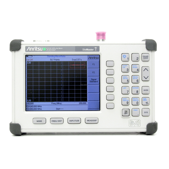
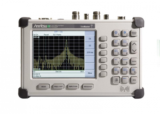
Chapter 2 Functions and Operations Display Overview Figure 2-2 illustrates some of the key information areas of the S331D display. TITLE BAR SWEEP DATA TIME POINTS CALIBRATION STATUS CURRENT MENU MESSAGE AREA Figure 2-2. S331D Display Overview…
-
Page 24: Front Panel Overview
Chapter 2 Functions and Operations Front Panel Overview The Site Master menu-driven user interface is easy to use and requires little training. Hard keys on the front panel are used to initiate function-specific menus. There are four function hard keys located below the status window: Mode, Frequency/Distance, Amplitude and Measure/Display.
-
Page 25: Function Hard Keys
Chapter 2 Functions and Operations Function Hard Keys MODE Opens the mode selection box (below). Use the Up/Down arrow key to select a mode. Press the key to implement. ENTER o Measurement Mode Freq — SWR Return Loss Cable Loss — One Port DTF — SWR Return Loss Power Monitor (External Detector)
-
Page 26: Keypad Hard Keys
ENTER Implements the current action or parameter selection. Turns the Anritsu Site Master on or off. When turned on, the saved system state at the last turn-off is restored. If the ESCAPE/CLEAR key is held down while the ON/OFF key is pressed, the factory preset state will be restored.
-
Page 27
Chapter 2 Functions and Operations The following keypad hard key functions are printed in blue on the keypad keys. This key is used to adust the display brightness. Use the Up/Down arrow key and ENTER to adjust the brightness. AUTO Automatically scales the status window for optimum resolution in cable SCALE and antenna analyzer mode. -
Page 28: Soft Keys
Chapter 2 Functions and Operations Soft Keys Each keypad key opens a set of soft key selections. Each of the soft keys has a correspond- ing soft key label area on the status window. The label identifies the function of the soft key for the current Mode selection.
-
Page 29
Chapter 2 Functions and Operations FREQ/DIST AMPLITUDE MODE=DTF: MEAS/DISP Resolu- SOFTKEYS: tion Single Bottom Sweep Trace DTF Aid Math Trace Overlay Fixed More On/Off Loss Select Trace Prop Cable List Window Page Up Page Back Down Back Bottom List Delete Trace Delete Traces… -
Page 30
Chapter 2 Functions and Operations FREQ/DIST AMPLITUDE MEAS/DISP Running SOFTKEYS: Center Averages Offset Hold Limit Zero ON/OFF Lower Limit Signal Upper Standard Limit Limit Units Select Standard Select Channel List Uplink Page Downlink Page Down Bottom List Back Select/ Deselect Show Selected Figure 2-7. -
Page 31
Chapter 2 Functions and Operations FREQ/DIST Displays the frequency and distance menu depending on the measurement mode. Frequency The frequency and distance menu for cable and antenna analyzer measurements Menu provides for setting sweep frequency end points when mode is selected. Se- Freq lected frequency values may be changed using the keypad or Up/Down arrow key. -
Page 32
Chapter 2 Functions and Operations MARKER Choosing MARKER in cable and antenna analyzer freq and dist mode causes the soft keys, below, to be displayed and the corresponding values to be shown in the message area. Selected frequency marker or distance marker locations may be changed using the keypad or Up/Down arrow key. -
Page 33
Chapter 2 Functions and Operations — Selects the M6 marker parameter and opens the M6 second level menu. — Turns the selected marker on or off. On/Off — Opens the selected marker parameter for data entry. Press Edit ENTER when data entry is complete or ESCAPE to restore the pre- vious value. -
Page 34
Chapter 2 Functions and Operations In cable and antenna analyzer or optional power meter mode, pressing the SYS key displays the following System menu soft key selections: — Displays a second level of system option functions: System Options — Displays a second level of functions: Clock —… -
Page 35
Chapter 2 Functions and Operations — Enter the minute (0-59) using the Up/Down arrow key or Minute the keypad. Press ENTER when data entry is complete or ESCAPE to restore the previous value. — Enter the month (1-12) using the Up/Down arrow key or the Month keypad. -
Page 36: Power Monitor, External Detector (Option 5)
Chapter 2 Functions and Operations Power Monitor, External Detector (Option 5) Selecting from the mode menu causes the soft keys, de- Power Monitor (External Detector) scribed below, to be displayed and the corresponding values shown in the message area. — Toggles between dBm and Watts. Units —…
-
Page 37: Symbols
Integrator Failure. Intermittent integrator failure may be caused by inter- ference from another antenna. Persistent integrator failure indicates a need to return the Site Master to the nearest Anritsu service center for repair. Lock fail indication. Check battery. (If the Site Master fails to lock with a fully charged battery, call your Anritsu Service Center.)
-
Page 38: Self Test
If the battery is low, or if the ambient temperature is not within the specified operational range, Self Test will fail. If Self Test fails and the battery is fully charged and the Site Master is within the specified operating temperature range, call your Anritsu Service Center found from: http://www.anritsu.com/Contact.asp 2-18…
-
Page 39: Error Messages
Battery voltage is less than 9.5 volts. Charge battery. If condition per- sists, call your Anritsu Service Center. External Power Low External supply voltage is less than 10 volts. Call your Anritsu Service Center PLL Failed Phase-locked loops failed to lock. Charge battery. If condition persists…
-
Page 40
Chapter 2 Functions and Operations Range Error Messages A listing of Range Error messages is provided in Table 2-3. Table 2-3. Range Error Messages Error Message Description RANGE The start (F1) frequency is greater than the stop (F2) frequency. ERROR:F1 > F2 RANGE The start (D1) distance is greater than the stop (D2) distance. -
Page 41
Chapter 2 Functions and Operations InstaCal Error Messages If the serial number of the connected InstaCal module does not match the serial number stored in the Site Master, the following message is displayed: The InstaCal characterization data stored in the Site Master is for a module different than the one currently connected. -
Page 42
The following error messages could be displayed on the Site Master when using the High Accuracy Power Meter mode with Power Sensor PSN50. If any error condition persists, contact your local Anritsu Service Center. Table 2-5. Option 19 Error Messages… -
Page 43: Battery Information
The battery can be charged while installed in the Site Master. Step 1. Turn the Site Master off. Step 2. Connect the AC-DC adapter (Anritsu part number: 40-168-R) to the Site Master charging port. Step 3. Connect the AC adapter to a 120 VAC or 240 VAC power source as appropriate for your application.
-
Page 44: Determining Remaining Battery Life
A blinking red light indicates less than 13 VDC is being supplied to the charger stand. Check that the correct AC charger adapter is connected to the charger stand. If the battery fails to charge, contact your nearest Anritsu Service Center. Determining Remaining Battery Life When the AC-DC adapter is unplugged from the Site Master, the battery indicator symbol will be continuously displayed at the top left corner of the Site Master display (Figure 2-7).
-
Page 45
Chapter 2 Functions and Operations Battery Life The NiMH battery will last longer and perform better if allowed to completely discharge before recharging. For maximum battery life, it is recommended that the NiMH battery be completely discharged and recharged once every three months. The charging circuitry inside the Site Master is designed to optimize the life of the battery. -
Page 46: Important Battery Information
· Recharge the battery only in the Site Master, or in an Anritsu approved charger. · If left unused, a fully charged battery will discharge itself over time.
-
Page 47: Introduction
Power On Procedure The Anritsu Site Master is capable of up to 1.5 hours of continuous operation from a fully charged, field-replaceable battery. Built-in energy conservation features allow battery life to be extended.
-
Page 48: Cable And Antenna Analyzer Mode
Chapter 3 Getting Started Cable and Antenna Analyzer Mode Selecting the Frequency For the OSL or FlexCal calibration method the frequency range for the desired measure- ment must be set. The Site Master will automatically set the frequency when a particular signal standard is selected, or the frequency can be manually set using the F1 and F2 soft keys.
-
Page 49
Chapter 3 Getting Started If a Test Port Extension Cable is to be used, the Site Master must be calibrated with the Test Port Extension Cable in place. The Test Port Extension Cable is a phase stable cable and is used as an extension cable on the test port to ensure accurate and repeatable measure- ments. -
Page 50
Chapter 3 Getting Started OSL Calibration Procedures In Cable and Antenna Analyzer Mode, if the message is displayed, or the test port Cal Off cable has been changed, a new calibration is required. The following procedures detail how to perform the OSL calibration. OPEN CALIBRATION SHORT… -
Page 51
Chapter 3 Getting Started FlexCal OSL Calibration Step 8. The currently selected calibration method can be viewed by pressing the SYS key, followed by the soft key. To change the calibration method, select Status the SYS key, followed by the soft key. -
Page 52
Chapter 3 Getting Started Offset Method An alternative to the termination method is to measure the return loss of a 20 dB offset. This is similar to measuring an antenna that has been specified to have a 20 dB return loss across the frequency of operation. -
Page 53
Chapter 3 Getting Started Standard InstaCal Calibration Step 1. Select OSL Cal by pressing the SYS key, followed by the Application Options soft key. The currently selected calibration method is indicated at the bottom of the status window. Use the soft key to select the OSL calibration CAL Mode method. -
Page 54: Examples
Chapter 3 Getting Started Auto Scale The Site Master can automatically set the scale to the minimum and maximum values of the measurement on the y-axis of the graph. This function is particularly useful for mea- surements in SWR mode. To automatically set the scale, press the AUTO SCALE key. The Site Master will automatically set the top and bottom scales to the minimum and maxi- mum values of the measurement with some margin on the y-axis of the LCD.
-
Page 55
Chapter 3 Getting Started Step 6. Using the arrow key, select the and press ENTER. Use the Up/Down Cable = arrow key to select the cable types stored in the standard Site Up/Down Standard Master cable lists (which cannot be edited) or choose , for additional ca- Custom bles. -
Page 56: All Modes
Chapter 3 Getting Started All Modes Save and Recall a Setup Saving a Setup Saving a cable and antenna analyzer setup configuration in memory will preserve the cali- bration information. Step 1. To save the configuration in one of the available user setup locations, press SAVE SETUP.
-
Page 57: Changing The Units
Chapter 3 Getting Started NOTES: More than one trace can be saved using the same alphanumeric name, as traces are stored chronologically, using the time/date stamp. Pressing the SAVE DISPLAY key will bring up the last saved trace name on the input line.
-
Page 58: Adjusting Limits
Chapter 3 Getting Started Adjusting Limits The Site Master offers two types of limits: a single horizontal limit line and segmented limits. Adjusting a Single Limit Step 1. Press the LIMIT key. Step 2. Press the soft key. Single Limit Step 3.
-
Page 59: Adjusting The Display Brightness
Chapter 3 Getting Started NOTES: The Site Master does not allow overlapping limit segments of the same type. That is, two upper limit segments cannot overlap and two lower limit segments cannot overlap. The Site Master also does not allow vertical limit segments. A limit segment in which the start and end frequencies are the same, but the limit values are differ- ent, cannot be specified.
-
Page 60: Printing
Chapter 3 Getting Started Printing Printing is accomplished by selecting an available printer and pressing the print key as de- scribed below. Refer to the particular printer operating manual for specific printer settings. Printing a Screen Step 1. Obtain the desired measurement display. Step 2.
-
Page 61: Using The Soft Carrying Case
Using the Soft Carrying Case The soft carrying case has been designed such that the strap can be unsnapped to allow the case to be easily oriented horizontally; thus allowing the Anritsu controls to be more easily accessed (Figure 3-5).
-
Page 63: Introduction
Chapter 4 Cable and Antenna Analyzer Measurements Introduction This chapter provides a description of cable and antenna analyzer measurements, including line sweeping fundamentals and line sweeping measurement procedures, available when the Site Master is in frequency or DTF mode. Line Sweep Fundamentals In wireless communication, the transmit and receive antennas are connected to the radio through a transmission line.
-
Page 64
Chapter 4 Cable & Antenna Measurements The performance of a transmission feed line system may be affected by excessive signal re- flection and cable loss. Signal reflection occurs when the RF signal reflects back due to an impedance mismatch or change in impedance caused by excessive kinking or bending of the transmission line. -
Page 65: Cw Mode/Rf Immunity
Precision Open/Short, Anritsu 22N50 or Precision Open/Short/Load, Anritsu OSLN50-1 or InstaCal Module ICN50B Precision Load, Anritsu SM/PL-1 Test Port Extension Cable, Anritsu 15RNFN50-1.5-R Optional 510-90 Adapter, DC to 7.5 GHz, 50 ohm, 7/16(F)-N(M) Device Under Test Transmission Feed Line with Antenna…
-
Page 66
Chapter 4 Cable & Antenna Measurements Procedure Step 1. Press the MODE key. Step 2. Select using the Up/Down arrow key and press ENTER. Freq-Return Loss Step 3. Set the start and stop frequencies, automatically by selecting a signal standard or manually using the F1 and F2 soft keys, as described on page 3-2. -
Page 67
Precision Open/Short, Anritsu 22N50 or Precision Open/Short/Load, Anritsu OSLN50-1 or Anritsu InstaCal Module, ICN50B Precision Load, Anritsu SM/PL-1 Test Port Extension Cable, Anritsu 15RNFN50-1.5-R Optional 510-90 Adapter, DC to 7.5 GHz, 50 ohm, 7/16(F)-N(M) Device Under Test Transmission Feed Line with Short Procedure — Cable Loss Mode Step 1. -
Page 68
Chapter 4 Cable & Antenna Measurements Figure 4-3 is an example of a typical transmission line cable loss measurement trace using a standard calibration. Figure 4-3. Typical Transmission Line Cable Loss Trace… -
Page 69
Precision Open/Short, Anritsu 22N50 or Precision Open/Short/Load, Anritsu OSLN50-1 or Anritsu InstaCal Module, ICN50B Precision Load, Anritsu SM/PL-1 Test Port Extension Cable, Anritsu 15RNFN50-1.5-R Optional 510-90 Adapter, DC to 7.5 GHz, 50 ohm, 7/16(F)-N(M) Device Under Test Transmission Feed Line with Load Procedure — DTF — Return Loss Mode The following steps explain how to make a DTF measurement in return loss mode. -
Page 70
Chapter 4 Cable & Antenna Measurements Figure 4-4 shows an example of a typical DTF return loss measurement trace using a FlexCal calibration. Figure 4-4. Typical DTF Return Loss Trace In the above example: Marker M1 marks the first connector, the end of the Site Master phase stable Test Port Extension cable. -
Page 71
Precision Open/Short, Anritsu 22N50 or Precision Open/Short/Load, Anritsu OSLN50-1 or Anritsu InstaCal Module, ICN50B Precision Load, Anritsu SM/PL-1 Test Port Extension Cable, Anritsu 15RNFN50-1.5-R Optional 510-90 Adapter, DC to 7.5 GHz, 50 ohm, 7/16(F)-N(M) Device Under Test Antenna Sub Assembly Procedure Step 1. -
Page 72
Chapter 4 Cable & Antenna Measurements The following trace is an example of an antenna return loss measurement trace using a FlexCal calibration.. Figure 4-5. Antenna Return Loss Trace Calculate the threshold value and compare the recorded Lowest Return Loss to the calcu- lated threshold value. -
Page 73: Power Measurement
The Site Master with Option 5 installed can be used for making power measurements with broadband RF detectors, such as the 10 MHz to 20 GHz Anritsu 560-7N50B. See the table of available RF detectors on page 1-3. The power monitor displays the measured power re- sults in dBm or Watts.
-
Page 74
Chapter 5 Power Monitor Displaying Relative Power Step 9. With the desired base power level input to the Site Master, press the REL soft key. The message area will show REL: ON and the power reading will indicate 100%. Step 10. Press the UNITS soft key to display power in dBm. Since REL is ON, the power reading will be in dBr, relative to the base power level. -
Page 75: Introduction
The Option 19 High Accuracy Power Meter connects to the PSN50 or MA24104A power sensor using an RS232 cable (Anritsu part number 800-441). A 9 to 18 VDC (<100 mA) power supply is needed to power either sensor (the MA24104A power sensor can also be powered with three AA batteries).
-
Page 76: Zeroing The Sensor
The Offset dB feature can be used to enter the value of any cables and attenuators. Power Measurement Required Equipment S331D Site Master RS232 Serial Cable, Anritsu P/N 800-441 Power Supply, Anritsu P/N 40-168-R PSN50 or MA24104A Power Sensor 30 dB, 50W, bi-directional, DC-8.5 GHz, N(m)-N(f), Attenuator, 3-1010-123 DC SUPPLY…
-
Page 77
Chapter 6 High Accuracy Power Meter Zero and Cal Step 6. Press the FREQ/DIST key. Step 7. To enter the frequency manually using the number keys, select the soft Center key. To select a known signal standard, press the soft key and Signal Standard use the Up/Down arrow key to select the desired standard. -
Page 78
Chapter 6 High Accuracy Power Meter Displaying Relative Power Step 21. Press the AMPLITUDE key. Step 22. With the desired base power level input to the sensor, press the soft key. The message area will show and the power reading will show 0 dB and Relative On 100%. -
Page 79: Introduction
Handheld Software Tools Introduction This chapter provides a description of the Anritsu Handheld Software Tools (HHST) program. Handheld Software Tools is a Windows 95/98/NT4/2000/ME/XP/Vista program for transferring measured traces, along with markers and limit lines, to the PC display. The program help function provides on screen instructions on display modification, trace over- lay, uploading and downloading traces, and multiple plot printing.
-
Page 80: System Requirements
Installation To install the Handheld Software Tools program: Step1. Insert the Anritsu Handheld Software Tools disk in the CD-ROM drive. Step2. From the Windows Start menu, select Run. Type: X:Setup.exe where X is the drive letter of your CD-ROM drive.
-
Page 81
Chapter 7 Handheld Software Tools Communication Port Setting The Handheld Software Tools communicates with the instrument through a standard serial COM port on the PC. Set the baud rate of the COM port to 115200. Select Start, Programs and select Software Tools. Step1. -
Page 82
Interface Cable Installation Communication between the instrument and the PC is accomplished over a null modem se- rial cable provided with the instrument (Anritsu part number 800-441, and optional USB to serial adapter, part number 551-1691, if required). Install the null modem serial interface cable to the RS232 Serial Interface con- Step1. -
Page 83: Using Handheld Software Tools
Cable Loss Power Monitor DTF (Distance to Fault) NOTE: Not all selections apply to every Anritsu Handheld instrument. Plot Capture to the PC To open the plot capture menus, select the capture icon on the button bar, or select the Capture drop down menu from the menu bar.
-
Page 84: Plot Properties
Chapter 7 Handheld Software Tools Plot Properties After downloading, certain plot properties and information can be modified. Select the Plot Properties or Plot Information icon. Plot Properties that can be changed include: Graph Titles Display Mode Scale/Limit Markers Misc. (Plot Display Parameters) Graph Titles After downloading the plot, the Main Title can be changed to reflect the site name or other descriptive information.
-
Page 85
NOTE: While all possible selections are displayed, some of these selections ap- ply only to specific models of Anritsu hand held instruments. Trace Overlay or Plot Overlay Trace Overlay is activated by the Mouse Function icon. Single-click on the Mouse Function icon to toggle. -
Page 86
Chapter 7 Handheld Software Tools To copy a metafile: Step1. Select the trace to be copied with the mouse cursor. Select Edit and then Copy. The file will copied to the clipboard, or select File Step2. and then Export to a Windows metafile. Open the target application (Microsoft Word, etc.). -
Page 87
Chapter 7 Handheld Software Tools Cable List A custom cable list can be created in Software Tools and uploaded to the Site Master. Some standard 1000 MHz, 2000 MHz, and 2500 MHz cables are stored in the Site Master and are listed in Appendix A of this User’s Guide. -
Page 88
Chapter 7 Handheld Software Tools To convert from Frequency Domain to Distance to Fault, follow these steps: Step1. Capture a plot or load a previously saved plot. Click the button on the toolbar (or choose Step2. Distance-to-fault Distance-to-Fault from the menu). -
Page 89: Signal Standards Editor
Chapter 7 Handheld Software Tools Signal Standards Editor The Signal Standards Editor is a software application for viewing, editing and creating sig- nal standards files. Select a signal standard entry from the list to make it active. The Signal Standards Editor can: ·…
-
Page 90
Chapter 7 Handheld Software Tools Retrieving Signal Standards Files Connection Manager must be connected to a test unit before retrieving a Signal Standards file. An active connection is indicated in the Status Bar at the bottom right corner of the ap- plication window. -
Page 91: Introduction
Master Software Tools Introduction This chapter provides an introduction to the Anritsu Master Software Tools (MST) program. Users of the legacy Handheld Software Tools (HHST) program are strongly encouraged to migrate to new MST platform. This new platform has numerous productivity advantages over HHST as described below in the list of features.
-
Page 92
Chapter 8 Handheld Software Tools · Language Editor – this utility allows you to add new or modify existing language tables. Languages available for selection are English, French, German, Spanish, Italian, Japanese, Chinese and Korean. All of these languages except for English can be edited. Up to two more custom languages can be loaded using this utility. -
Page 93
Chapter 8 Handheld Software Tools Figure 8-3. MST Product Update Tools used to download the latest software and firmware Figure 8-4. DAT file conversion tool used to convert existing SPA and Cable & Antenna traces to MST NOTE: New firmware is not compatible with Master Software Tools version 1.25 or older. -
Page 94: Minimum System Requirements
Chapter 8 Handheld Software Tools Minimum System Requirements · Microsoft Windows 2000 (Service Pack 4 or above), Windows XP (Service Pack 2 or above), or Windows VISTA · Microsoft .NET Framework, Version 2.0 · Intel Pentium 233 MHz microprocessor (Pentium III 350 MHz or better recommenced) ·…
-
Page 95
Appendix A Windowing Introduction The FREQ/DIST menu (page 2-11) provides for setting the cable loss and relative propa- gation velocity of the coaxial cable. The key opens a menu of FFT windowing Window types for the DTF calculation. The theoretical requirement for inverse FFT is for the data to extend from zero frequency to infinity. -
Page 96
Appendix A Windowing D i s t a n c e T o F a u l t — 1 0 — 1 5 — 2 0 — 2 5 — 3 0 R e t u r n L o s s ( d B ) — 3 5 — 4 0 — 4 5… -
Page 97
Appendix A Windowing D i s t a n c e T o F a u l t — 1 0 — 1 5 — 2 0 — 2 5 — 3 0 R e t u r n L o s s ( d B ) — 3 5 — 4 0 — 4 5… -
Page 99
Index hold ….2-7, 2-17 accessories ….1-2, 1-4 InstaCal … . 1-11, 2-21, 3-2 battery . -
Page 100
resolution ….4-8 trace overlay … . . 7-1, 7-7 return loss ….4-2, 4-9 trigger single sweep . -
Page 102
Anritsu Company Prints on Recycled Paper with Vegetable Soybean Oil Ink Anritsu Company 490 Jarvis Drive Morgan Hill, CA 95037-2809 http://www.anritsu.com/…
Каталог оборудования > ВЧ- и СВЧ-измерительные приборы > Портативные приборы > Портативные анализаторы кабелей и антенн > Site Master S331D — анализатор кабелей и антенн от 25 МГц до 4,0 ГГц
По желанию заказчика прибор поставляется с русифицированным меню.
Описание анализатора S331D Site Master:
Портативный анализатор кабелей и антенн S331D Site Master, охватывающий спектр частот от 25 МГц до 4,0 ГГц, является стандартом «de facto» для установки, ввода в эксплуатацию, обслуживания кабелей и антенных систем базовых станций беспроводной связи, выявления и устранения неисправностей в них. Точный, универсальный, прочный и по-настоящему портативный (вес менее 2,3 кг вместе с аккумуляторной батареей), S331D Site Master идеально подходит для специалистов любого уровня квалификации, работающих в области ОВЧ, радиовещания, пейджинговой и сотовой связи, PCS/GSM, 3G, ISM, WLAN и WLL.
S331D Site Master позволяет проводить следующие виды измерений: точные измерения КСВ по напряжению, обратные потери, потери в кабеле и опциональные измерения мощности. Метод частотной рефлектометрии (FDR) обеспечивает лучший анализ расстояния до повреждения (DTF) для точного определения неисправности. Запатентованное подавление высокочастотной интерференции обеспечивает точные и повторяемые измерения в присутствии сильных помех. Программное обеспечение анализа данных в дополнение к созданию профессиональных отчетов позволяет оценить изменения в системе, проблемы и производительность.
Со скоростью сканирования менее 2,5 миллисекунд на точку прибор экономит специалистам время и позволяет провести легкую идентификацию временных проблем в режиме реального времени. Широкополосная калибровка FlexCal от 25 МГц до 4,0 ГГц позволяет выявить неисправность в кабелях и антенных системах без необходимости в проведении сложных калибровок и установок настроек. Содержащийся в приборе список наиболее распространенных во всем мире стандартов сигналов исключает необходимость помнить частоты систем и вводить вручную значения начальной и конечной частоты. Возможность измерения средних потерь в кабеле исключает необходимость подсчитывать значения потерь в кабеле по известному погонному ослаблению. Внутренний измеритель мощности (Опция 29) точно измеряет мощность передатчика базовой станции. Высокоточный измеритель мощности (Опция 19) обеспечивает истинные среднеквадратичные измерения в диапазоне от 50 МГц до 6 ГГц.
Возможности анализатора S331D Site Master:
- Портативный, работающий от аккумулятора;
- Вес менее 2,3 кг, включая аккумуляторную батарею;
- Встроенный список наиболее распространенных во всем мире стандартов сигналов и частот каналов;
- Жидкокристаллический цветной дисплей, различимый при дневном свете;
- Высокая защищенность от помех;
- Различные опции измерения мощности;
- Определяет проблемы на большом расстоянии с количеством точек сканирования 517;
- Встроенные и редактируемые списки стандартов сигналов и стандартов кабелей;
- Мультиязычный пользовательский интерфейс; английский, франсузский, китайский, японский, испанский, немецкий/русский языки;
- Возможность сохранения до 30 настроек измерений (10 — анализ кабелей и антенн, 5 — анализ T1, 5 — анализ E1, 5 — измеритель мощности, 5 — высокоточный измеритель мощности);
- Возможность сохранения до 300 результатов измерений;
- Цифробуквенное обозначение данных измерений;
- Автоматическое прикрепление к данным даты и времени измерения;
- Перезаряжаемая, легко заменяемая батарея;
- Измерение расстояния в метрах и футах;
- Интерактивные информационные экраны позволяют ввести погонное ослабление и относительную скорость распространения кабеля;
- 6 маркеров, простые и сложные (сегментированные) ограничительные линии;
- Интерфейс связи — RS232.
В базовый комплект поставки анализатора S331D Site Master входит:
- перезаряжаемая аккумуляторная батарея;
- мягкая сумка для переноски;
- адаптер для зарядки и работы прибора от сети переменного тока 220 В с сетевым кабелем;
- адаптер для зарядки и работы прибора от автомобильного прикуривателя 12 В;
- программное обеспечение на компакт-диске;
- интерфейсный RS-232 кабель для связи с персональным компьютером;
- переходник с COM(штырь) на USB-A(штырь) для подключения прибора к ПК по интерфейсу USB;
- руководство пользователя на русском языке в печатном виде.
Конфигурирование анализатора S331D Site Master:
|
Наименование |
Описание |
| S331D | Анализатор кабелей и антенн от 25 МГц до 4,0 ГГц, цветной экран, разъем выходного порта N(f) |
| S331D/2 | Опция 2, Уменьшение нижней границы анализа кабелей и антенн с 25 МГц до 2 МГц |
| S331D/5 | Опция 5, Монитор мощности (эта опция не может быть заказана с Опцией 50, в состав не входит и указывается при заказе отдельно детектор мощности 5400-71N50, 560-7K50, 560-7N50B, 560-7S50B или 560-7VA50) |
| S331D/16 | Опция 16, Увеличение верхней границы анализа кабелей и антенн с 4,0 ГГц до 6,0 ГГц |
| S331D/19 | Опция 19, Высокоточный измеритель мощности (в состав не входит и указывается при заказе отдельно высокоточный датчик мощности PSN50 или MA24104A) |
| S331D/29 | Опция 29, Внутренний измеритель мощности, разъем входного порта N(f) |
| S331D/31 | Опция 31, Приемник GPS (в состав входит GPS-антенна ANRITSU # 2000-1410) |
| S331D/50 | Опция 50, Тестер T1/E1 (эта опция не может быть заказана с Опцией 5) |
| S331D/RUS | Опция RUS, Русифицированный интерфейс прибора |
| 5400-71N50 | Детектор мощности; от 1 МГц до 3,0 ГГц; разъем N(m); 50 Ом (для Опции 5) |
| 560-7K50 | Детектор мощности; от 10 МГц до 40,0 ГГц; разъем K(m); 50 Ом (для Опции 5) |
| 560-7N50B | Детектор мощности; от 10 МГц до 20,0 ГГц; разъем N(m); 50 Ом (для Опции 5) |
| 560-7S50B | Детектор мощности; от 10 МГц до 20,0 ГГц; разъем WSMA(m); 50 Ом (для Опции 5) |
| 560-7VA50 | Детектор мощности; от 10 МГц до 50,0 ГГц; разъем V(m); 50 Ом (для Опции 5) |
| PSN50 | Высокоточный датчик поглощаемой мощности; от 50 МГц до 6,0 ГГц; от 1 мкВт до 0,1 Вт; разъем N(m); 50 Ом (для Опции 19) |
| MA24104A | Высокоточный датчик проходной мощности; от 600 МГц до 4,0 ГГц; от 2 мВт до 150 Вт; разъемы N(m) — N(f); 50 Ом (для Опции 19) |
Перед проведением измерений параметров антенн и линий прибор необходимо откалибровать. Калибровку прибора также необходимо проводить при изменении частотного диапазона измерений или выходе температуры за пределы температурного диапазона проведённой калибровки. Для выбора калибровочных элементов перейдите в подраздел «Калибровочные элементы«.
При измерениях мощности (Опции 5, 19 и 29) рекомендуется использовать аттенюатор, например, двунаправленный аттенюатор 42N50A-30 (рабочий диапазон частот от 0 до 18,0 ГГц, ослабление 30 дБ, максимальная рассеиваемая мощность 50 Ватт, разъемы N(m) — N(f)).
Возможно, при измерениях потребуются измерительные кабели и переходники.
Скачать
Site Master is the preferred cable and antenna analyzer of
wireless providers, contractors and installers.
Site Master
™
S331D/S332D
Cable and Antenna Analyzer
MS2712
MS2712
MS2712
SiteMaster
SpectrumMaster
CellMaster
MS2711D Spectrum Master
S331D Site Master
SiteMaster
SpectrumMaster
MT8212A Cell Master
CellMaster
Color display option shown
Programming Manual
Краткое содержание страницы № 1
™
Site Master
S331D/S332D
Cable and Antenna Analyzer
Site Master is the preferred cable and antenna analyzer of
wireless providers, contractors and installers.
Color display option shown
S331D Site Master SiteMaster MS2711D Spectrum Master MT8212A Cell Master CellMaster MS2712
MS2712 SpectrumMaster MS2712
SiteMaster SpectrumMaster CellMaster
Краткое содержание страницы № 2
WARRANTY The Anritsu product(s) listed on the title page is (are) warranted against defects in materi- als and workmanship for one year from the date of shipment. Anritsu’s obligation covers repairing or replacing products which prove to be defective during the warranty period. Buyers shall prepay transportation charges for equipment re- turned to Anritsu for warranty repairs. Obligation is limited to the original purchaser. Anritsu is not liable for consequential damages. LIMITATION OF WARRANTY
Краткое содержание страницы № 3
Table of Contents Programming Overview . . . . . . . . . . . . . . . . . . . . . . . . . …………1 Control Byte Summary. . . . . . . . . . . . . . . . . . . . . . …………….3 Control Byte Descriptions . . . . . . . . . . . . . . . . . . . . …………….7 Setup System – Control Byte #1 (01h)………………………………7 Set Site Master VNA Frequency – Control Byte #2 (02h)……………………..7 Select Measurement Mode – Control Byte #3 (03h)………………………..
Краткое содержание страницы № 4
Upload Sweep Trace – Control Byte #36 (24h) …………………………62 Get Options – Control Byte #37 (25h) ……………………………..71 Query Power Level – Control Byte #39 (27h) (Option 29 only) ………………….72 Set Power Meter Units – Control Byte #40 (28h) (Option 29 only) ………………..72 Power Meter Relative Mode On/Off – Control Byte #41 (29h) (Option 29 only) ………….73 Power Meter Offset Mode On/Off – Control Byte #42 (2Ah) (Option 29 only) …………
Краткое содержание страницы № 5
Set Spectrum Analyzer Marker to Peak – Control Byte #109 (6Dh) ………………..86 Set Spectrum Analyzer Marker to Center – Control Byte #110 (6Eh) ……………….86 Set Spectrum Analyzer Attenuation – Control Byte #111 (6Fh) ………………….87 Set Site Master VNA Segmented Limit Lines – Control Byte #112 (70h) ……………..87 Set Spectrum Analyzer Multiple Limit – Control Byte #113 (71h) ………………..88 Set Return Spectrum Analyzer Sweep Time – Control Byte #114 (72h)…
Краткое содержание страницы № 6
Set T1/E1 Receive Input Configuration Options — Control Word (A013h) (Option 50 only)…….101 Set T1/E1 Measurement Duration — Control Word (A014h) (Option 50 only) …………..101 Set T1/E1 Data Logging — Control Word (A015h) (Option 50 only) ……………….101 Read T1/E1 dBdsx — Control Word (A016h) (Option 50 only) ………………….102 Read T1/E1 Frequency — Control Word (A017h) (Option 50 only) ………………..102 Read T1/E1 Frequency Cal — Control Word (A018h) (Option 50 on
Краткое содержание страницы № 7
Programming Overview NOTE: This programming manual is written exclusively for Anritsu Site Master Models S331D and S332D. For information on firmware upgrades, contact your local Anritsu Service Center. Commands listed in this manual are not all backward-compatible with earlier Anritsu models. General Description The Site Master must first be set into “remote” mode for communication with a computer. Remote mode differs from normal repetitive sweep and single-sweep modes. During remote mode, the
Краткое содержание страницы № 8
Exiting Remote Mode To exit remote mode, send the Exit Remote Control byte #255 (FFh) to the Site Master. The Site Master sends a response byte of 255 (FFh) then exits remote mode. Remote mode can also be exited by pressing the ESCAPE/CLEAR front panel key. Remote Mode Changes to Site Master Operating Parameters System parameters changed during remote mode remain changed for normal operation after the unit exits remote mode. However, the changes are not automatically written to the non-volatile
Краткое содержание страницы № 9
Control Byte Summary Control Byte Watchdog Name Description # Timer 1 (01h) Setup System Sets system status flags and switches Yes 2 (02h) Set VNA Frequency Sets Site Master VNA frequency range Yes 3 (03h) Select Measurement Mode Sets current Site Master measurement mode Yes 4 (04h) Set VNA Scale Sets Site Master VNA scale values Yes 5 (05h) Set VNA Marker Sets position and on/off status of Site Master markers in VNA modes Yes 6 (06h) Set VNA Single Limit Sets position and on/off status of the S
Краткое содержание страницы № 10
Control Byte Watchdog Name Description # Timer 42 (2Ah) Power Meter Offset Mode Enables or disables Power Meter offset Yes 43 (2Bh) Power Meter Zero Mode Enables or disables Power Meter zeroing mode Yes Power Meter RMS 44 (2Ch) Sets Power Meter RMS Averaging. Yes Averaging On/Off Power Meter Center 45 (2Dh) Sets the center frequency and span frequency for the Power Meter mode Yes Frequency and Span 48 (30h) Trigger Sweep Starts the next sweep —- 50 (32h) Check Battery Status Returns smart batter
Краткое содержание страницы № 11
Control Byte Watchdog Name Description # Timer Set Spectrum Analyzer 106 (6Ah) Sets the Spectrum Analyzer resolution BW frequency (obsolete) Yes Resolution Bandwidth Freq Set Spectrum Analyzer 107 (6Bh) Sets the Spectrum Analyzer video BW frequency (obsolete) Yes Video Bandwidth Freq Set Spectrum Analyzer 108 (6Ch) Sets the Spectrum Analyzer sweep mode Yes Sweep Mode Set Spectrum Analyzer 109 (6Dh) Sets specified marker to peak value of the sweep Yes Marker to Peak Set Spectrum Analyzer 110 (6Eh
Краткое содержание страницы № 12
Control Byte Watchdog Name Description # Timer Set T1/E1 Error Insert A004h Sets the Insertion Error type and the number of errors Yes Type/Value A005h Set T1/E1 Framing Mode Sets the Framing Mode of T1/E1 measurement Yes Start and Stop T1/E1 A006h Toggles state of T1 and E1 measurements —- Measurement Insert Error for T1/E1 A007h Inserts the error defined into the data flow —- Measurement A008h Get T1/E1 Pattern Returns the current pattern for T1 and E1 modes —- Get T1/E1 Frame Sync A009h Retur
Краткое содержание страницы № 13
Control Byte Descriptions Setup System – Control Byte #1 (01h) Description: Sets system status flags and switches. The current value of the flags can be obtained by executing command #29, Query System Setup, and parsing the values from the appropriate bytes. The Site Master acts on the entire byte. So, the state of each of the bits must be defined every time the command is issued. See control byte #29 (1Dh) response byte 170 (VNA mode) or response bytes 275 and 276 (SPA mode) for current Site Ma
Краткое содержание страницы № 14
Select Measurement Mode – Control Byte #3 (03h) Description: Sets the measurement mode of the Site Master. The response byte will not be sent until the mode change is complete. See control byte #29 (1Dh) response byte 3 for the current Site Master measurement mode. Bytes to Follow: 1 byte 1) Measurement Mode 00h: RL Frequency 01h: SWR Frequency 02h: Cable Loss Frequency 10h: RL Distance 11h: SWR Distance 30h: Spectrum Analyzer Mode 31h: Transmission Mode (Option 21 only) 40h: Power Meter Mode (O
Краткое содержание страницы № 15
Set Site Master VNA Marker – Control Byte #5 (05h) Description: Sets an individual marker position and status in the current VNA measurement mode. See Control Byte #102 to set markers in Spectrum Analyzer mode. The Site Master sets the position of a marker by its relative position on the graph. The lowest position is 0 at the start frequency (or distance). The highest position is the data point number at the stop frequency (or distance). For example, for a resolution of 130, the first frequency
Краткое содержание страницы № 16
Notes: Return Loss & Cable Loss: Limit should be sent as ( dB * 1000 ) Maximum value sent is 60000 which represents 60.00 dB Minimum value sent is 0 which represents 0.0 dB SWR: Limit is in thousandths (of ratio), so it should be sent as ( ratio * 1000 ) Maximum value sent is 65530 which represents 65.53 Minimum value sent is 1000 which represents 1.00 Set DTF Parameter – Control Byte #7 (07h) Description: Sets Distance to Fault parameters. Be aware using this control byte. The distance to fault
Краткое содержание страницы № 17
Set Time/Date – Control Byte #8 (08h) Description: Sets the current time and date. This Time/Date is stamped into all stored sweeps (for users’ reference). The Site Master stores bytes as ASCII text. Recommended time form is “hh:mm:ss” (hour:minute:sec). Recommended date format is “mm/dd/yyyy” (month/day/year). The current time setting can be found by using control byte #33 to recall trace 0 and examining response bytes 31-38. The current date setting can be found by using control byte #33 to re
Краткое содержание страницы № 18
Bytes to Follow: 1 byte 1) Serial Port Echo Status 00h = Off 01h=On Site Master Returns: 1 byte 1) 255 (FFh) Operation Complete Byte 224 (E0h) Parameter Error : Invalid serial port echo status 238 (EEh) Time-out Error Site Master VNA Single Sweep Mode On/Off – Control Byte #11 (0Bh) Description: Enables or disables the Single Sweep Mode during Site Master VNA modes of operation. For Single Sweep Mode during Spectrum Analyzer mode of operation, see control byte #108 (6Ch). Single Sweep Mode activ
Краткое содержание страницы № 19
Sequence Site Master Calibration – Control Byte #13 (0Dh) Description: Initiates a calibration step. The Site Master must be calibrated to give accurate measurements. The command sequence must be sent in correct order. i.e. Open -> Short -> Load. You can also abort the calibration by command – “Abort” before the command — “Load” is sent. Once command — “Load” is sent, calibration is completed, and the old calibration data is lost. The unit under test returns #255(FFh) upon receiving the command,
Краткое содержание страницы № 20
Store Sweep Trace – Control Byte #16 (10h) Description: Saves current trace to the next available memory location. Trace name can be set using control byte #9, “Set Reference Number” before executing this command. Bytes to Follow: 0 bytes Site Master Returns: 5 bytes 1-4) Time/Date Stamp (In long integer format) 5) Operation result: 255 (FFh) Operation Complete Byte 224 (E0h) Out of memory (Memory full) 238 (EEh) Time-out Error Recall Sweep Trace – Control Byte #17 (11h) NOTE: This command exist
Каталог оборудования
Код товара: 265
Артикул: 0003
Цена: по запросу
![]()
Предлагаем купить Anritsu Site Master S331D Russian по разумной цене – в комплект входит руководство с подробными инструкциями по эксплуатации.
Диапазон частот: 25 МГц — 4000 МГц. Измерение обратных потерь, КСВ, затухания в кабеле, расстояния до неоднородности в кабеле. Встроенный измеритель мощности (опция). + анализатор потоков Т1/Е1 (опция).
Файлы для загрузки
| Наименование | Ссылка |
|---|---|
| Техническое описание S331D-332D (English) | Загрузить |
Информация
Site Master S331D осуществляет следующие измерения: коэффициент стоячей волны по напряжению (КСВ), обратные потери, потери в кабеле (однопортовое измерение), расстояние до неоднородности в кабеле, излучаемая мощность и измерения потоков T1/E1.
Высокая помехозащищенность и невосприимчивость к интерференции — это запатентованные особенности данного прибора, что позволяет проводить измерения на узлах с большим количеством источников излучения. Программное обеспечение для обработки данных на ПК позволяет отслеживать различные изменения, происходящие в системе с генерацией соответствующей документации.
Задачи, решаемые с помощью анализатора S331D Site Master:
- измерения беспроводных сетей и систем связи;
- тестирование АФУ для ОВЧ, телерадиовещания, пейджинговой связя, сотовой связи PCS/GSM, 3G, ISM, WLAN и WLL приложений;
- измерение обратных потерь;
- измерение расстояние до повреждения;
- измерение потерь в кабеле и тестирование производительности передатчика базовой станции;
- измерение мощности в канале;
- измерение коэффициента мощности в соседнем канале;
- оценка занимаемой полосы частот.
Возможности анализатора S331D Site Master:
- портативный, возможность питания от аккумулятора, вес вместе с аккумулятором 2,5 кг, размеры 25 x 17,5 x 6 см;
- встроенная система наиболее используемых стандартов сигналов и частотных каналов;
- высокая помехозащищенность и невосприимчивость к интерференции;
- большой диапазон и высокая разрешающая способность для нахождения неоднородности в кабеле;
- возможность выбора типа тестируемого кабеля из списка, состоящего из более 95 позиций;
- возможность работы в любых климатических условиях;
- возможность работы с прибором на различных языках: английский, немецкий или русский, французский, испанский, японский, китайский;
- интуитивный и легкий в обращении интерфейс;
- возможность сохранения до 25 пользовательских конфигураций параметров тестирования и до 200 результатов измерений во внутренней флэш-памяти.
- возможность установки до 6 маркеров, границ измерений и диапазонов измерений;
- количество точек измерения 130, 259 и 517 для оптимального разрешения и нахождения неоднородностей в кабеле на больших расстояниях;
- автоматическая установка времени и даты сохранения результатов;
- калибровочный модуль InstaCal™ упрощает калибровку прибора;
- измерение расстояния до неоднородности в кабеле в футах или в метрах;
- система подсказок с типовыми значениями затухания и скорости распространения сигнала в кабеле;
- скорость свипирования < 500 мс/свип для определения периодических проблем в кабеле в режиме реального времени;
- погрешность при измерении мощности ± 0,5 дБ;
- анализ помеховых сигналов;
- защита от перенапряжения;
- RS232 интерфейс.
В базовый комплект поставки анализатора Site Master S331D входит:
- перезаряжаемая аккумуляторная батарея;
- мягкая сумка для переноски;
- адаптер для зарядки и работы прибора от сети переменного тока 220 В с сетевым кабелем;
- адаптер для зарядки и работы прибора от автомобильного прикуривателя 12 В;
- программное обеспечение на компакт-диске;
- интерфейсный RS-232 кабель для связи с персональным компьютером;
- переходник с COM(штырь) на USB-A(штырь) для подключения к ПК, на котором отсутствует или уже используется COM-порт;
- руководство пользователя на русском языке в печатном виде.
Другое оборудование этого раздела
ВНИМАНИЕ!
- Вся информация на сайте носит справочный характер и не является публичной офертой, определяемой положениями Статьи 437 Гражданского кодекса Российской Федерации.
- Технические параметры (спецификация) и комплект поставки товара могут быть изменены производителем без предварительного уведомления.
- Приведённые цены являются ориентировочными и на момент заказа требуют уточнения.
- Наша компания принимает оплату только по безналичному расчёту.
- Продукция, предлагаемая нашей компанией, не имеет бытового или иного назначения, не связанного с осуществлением предпринимательской деятельности.
Аском контрольно измерительное оборудование, Россия, г. Москва, +7 (495) 220-99-08, e-mail: info@as-com.ru
© 2023 Компания Аском: контрольно-измерительные приборы