
Краткие характеристики
Выходная мощность
420 ВА / 260 Вт
Форма выходного сигнала
ступенчатая аппроксимация синусоиды
Время переключения на батарею
2 мс
Количество выходных разъемов питания
4 (из них с питанием от батарей — 3)
Перейти к характеристикам
![]()
+ 845 бонусов за покупку
чтобы получить их
Варианты получения заказа
Самовывоз из магазина
начиная с 18 сентября, бесплатно
Доставка курьером
начиная с 17 сентября, 449 ₽
Пункт выдачи CDEK
начиная с 19 сентября, 1 134 ₽
Описание
Обеспечение бесперебойного питания нагрузки при отсутствии напряжения в сети в течение времени разряда аккумуляторной батареи, стабилизация выходного напряжения, фильтрация высокочастотных помех, защита сетевой линии от импульсов перенапряжения.
Характеристики ИБП APC Smart-UPS SC SC420I
Технические характеристики
Выходная мощность
420 ВА / 260 Вт
Форма выходного сигнала
ступенчатая аппроксимация синусоиды
Время переключения на батарею
2 мс
Количество выходных разъемов питания
4 (из них с питанием от батарей — 3)
Тип выходных разъемов питания
IEC 320 C13 (компьютерный)
Время работы при половинной нагрузке
13.5 мин
Макс. поглощаемая энергия импульса
320 Дж
Все характеристики
Не является публичной офертой
Информация о товаре носит справочный характер и не является публичной офертой. Характеристики, комплект поставки и внешний вид товара могут отличаться от указанных или быть изменены производителем без предварительного уведомления. Перед покупкой проверяйте информацию на официальном сайте производителя.
Если вы заметили ошибку или неточность в описании товара, пожалуйста, выделите часть текста с ошибкой и нажмите кнопку «Сообщить об ошибке».
Отзывов пока нет
Будьте первым, кто напишет отзыв о товаре, и получите бонусы

®
Smart-UPS v/s
120 VAC
Uninterruptible Power Source
Onduleur
Sistema de Alimentación Ininterrumpida
Models 420, 650, 1000, 1400
User’s Manual/Manuel de l’utilisateur/Manual de Usario
English/Français/Español


Contents/Sections/Indice
English …………………………………………………………………………….. 1
Français ………………………………………………………………………….. 19
Español ………………………………………………………………………….. 39
Please note: The troubleshooting section (section  offers solutions for most of the difficulties you may encounter with this UPS. Before calling customer service, please have available your UPS’s serial number (see label on the rear of the UPS). A returned materials authorization (RMA) number is required for all return shipments to APC. Do not send return shipments to APC without an RMA number. See section 9.
Veuillez noter : La section «En cas de problème» (section offre des solutions pour la plupart des difficultés
rencontrées lors de l’utilisation de l’onduleur. Si vous appelez notre service clientèle, veuillez avoir à portée
de main le numéro de série de votre onduleur (sur l’étiquette située sur le panneau arrière de l’onduleur). Un
numéro d’autorisation de retour de marchandise (RMA) est nécessaires pour tous les renvois à APC (les
conditons de service et d’intervention varient selon les pays. Veuillez contacter votre agence APC pour tout
renseignement sur les spécificités relatives à votre pays). Ne renvoyez aucun appareil à APC sans ce numéro.
Reportez-vous à la section 9.
Sírvase tomar nota: La sección de detección y solución de problemas (sección ofrece soluciones para la
mayoría de las dificultades que puede usted encontrar con este UPS. Antes de llamar a servicio al cliente,
sírvase tener disponible su número de serie del UPS (verlo en la etiqueta en la parte posterior del UPS). Se
requiere un número de autorización de devolución de materiales (RMA) para todos los envíos de devolución a
APC. No envíe despachos de devolución a APC sin un número RMA. Vea la sección 9.
Serial number:/Numéro de série:/Número de serie:
Toll free technical support:
Numéro vert de l’assistance technique:
Número de teléfono sin costo para apoyo
técnico:
United States and Canada 1-800-800-4272
Ireland 1-800-702000
U. K. 0800-132990
In areas without toll free numbers, call:
+1 401 789 5735 (USA) or
+353 91 702020 (Ireland)
Return shipment addresses:
Adresse d’expédition des renvois :
Direcciones para devolver mercadería:
American Power Conversion Corporation
132 Fairgrounds Road
P. O. Box 278
West Kingston, Rhode Island 02892
USA
American Power Conversion Corporation
(A. P. C.) b. v.
Ballybritt Business Park
Galway
Ireland
English
Entire contents copyright © 1994 American Power Conversion. All rights reserved; reproduction in whole or in part without
permission is prohibited. Smart-UPS v/s is a registered trademark of APC. All other trademarks are the property of their
respective owners.

Part Number 990-2016
Revised 11/94

1. Introduction ………………………………………………………………… 1
2. Safety …………………………………………………………………………. 3
3. Presentation ………………………………………………………………… 4
4. Installation ………………………………………………………………….. 5
5. Operation …………………………………………………………………… 8
6. Alarms ……………………………………………………………………….. 9
7. Options ………………………………………………………………………. 9
8. Troubleshooting …………………………………………………………. 10
9. Service ……………………………………………………………………… 11
10. Battery Replacement …………………………………………………… 12
11. Storage …………………………………………………………………….. 14
12. Specifications …………………………………………………………….. 15
13. How to Determine On-battery Run Time …………………………. 18
1. Introduction
1.1 Thank you!
Thank you for selecting this uninterruptible power source (UPS). It is designed for many years of
reliable, maintenance-free service.
English
Important!
Please read this manual. It provides safety, installation, and operating instructions that will help
you get the fullest performance and service life from your UPS. This manual describes the inner
workings of the UPS and how they relate to providing superior protection from utility power problems such as blackouts, brownouts, sags, swells, EMI/RFI noise, and surges. Also included are instructions for obtaining factory service, if necessary.
If you have a problem with the UPS, please refer to this manual before calling customer service.
The troubleshooting section (section can help with most situations typically encountered when
using the UPS.
Please save the packaging materials!
The UPS’s shipping materials are designed with great care to provide protection during shipping.
These materials are invaluable if you ever have to return the UPS for service. Damage sustained
during transit is not covered under the warranty.
1
1.2 Radio Frequency Interference
This equipment has been tested and found to comply with the limits for a Class B digital device,
pursuant to Part 15 of the FCC Rules and the Class B limits for radio noise emissions from digital
apparatus set out in the Radio Interference Regulations of the Canadian Department of Communications. These limits are designed to provide reasonable protection against harmful interference in
a residential installation. This equipment generates, uses and can radiate radio frequency energy
and, if not installed and used in accordance with the instructions, may cause harmful interference
to radio communications.
However, there is no guarantee that interference will not occur in a particular installation. If this
equipment causes interference to radio or television reception, which can be determined by turning the equipment off and on, the user is encouraged to try to correct the interference by one or
more of the following measures:
n reorient the receiving antenna
n increase the separation between the equipment and the receiver
n connect the equipment to an outlet on a circuit different from that to which the receiver is
connected
n consult the dealer or an experienced radio/TV technician for help.
Shielded communications interface cables must be used with this product.
War ning: Changes or modifications to this unit not expressly approved by the party responsible
for compliance could void the user’s authority to operate the equipment.
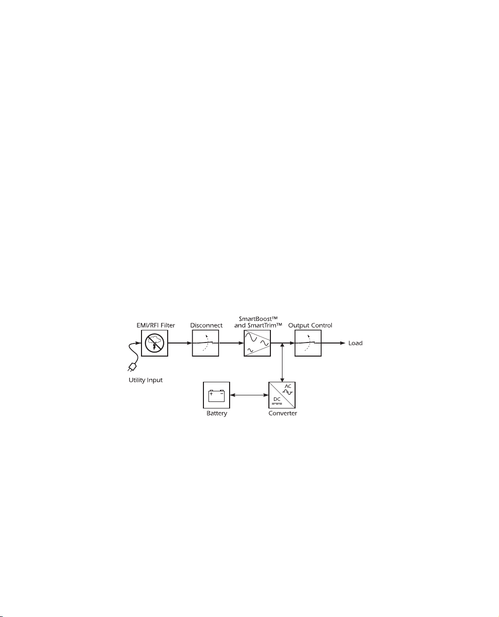
1.3 Theory of Operation
This high-performance, line-interactive, uninterruptible power source (UPS) provides clean, reliable, AC power to computer systems — protecting them from power blackouts, brownouts, swells,
sags, surges, and interference.
Normally, the UPS operates “on-line,” supplying power from the utility input to the load (workstation, server, or other device). The converter circuitry is used to maintain an optimal float
charge level on the battery.
When the utility fails, the disconnect switch opens and the converter supplies AC power to the
load. The loads operate normally until shut down or until the battery is exhausted. The UPS automatically transfers the load back to utility power and recharges the batteries when the line voltage
returns to normal.
The UPS also provides surge protection and EMI/RFI filtering, as well as SmartBoost™ and
SmartTrim™ (automatic voltage regulation), which corrects high and low input voltage without
drawing power from the battery.
2

Output control uses the UPS’s remote interface to turn the load on or off, without disabling other
UPS functions.
1.4 Features
Intelligent Battery Management
The UPS provides visual and audible indications of the battery’s status including low battery and
replace battery conditions.
The UPS exercises the battery during its self-test, and will detect a weak battery before it is put
into service. The UPS normally performs a self-test at power up and every 14 days thereafter. Selftests can also be conducted manually with the on/test button at any time. See section 5.2.
The UPS features user-replaceable hot-swappable batteries. Batteries can be replaced without having to remove power from the loads or send the UPS in for service.
Power Management Software
This UPS offers advanced features when connected via the computer interface to a device using
power management software.
Telephone Line and Network Surge Protection
This UPS provides advanced single telephone line or 10Base-T network surge suppression through
the modular connectors on the back panel. See section 4.
2. Safety
English
CAUTION!
n To reduce the risk of electric shock in conditions where load equipment grounding cannot be
verified, disconnect the UPS from the AC power outlet before installing a computer interface
or accessory slot signal cable. Reconnect the power cord only after all signaling connections
are made.
n Connect the UPS to a two-pole, three-wire grounding AC power outlet. The receptacle must
be connected to appropriate branch protection (fuse or circuit breaker). Connection to any
other type of receptacle may result in a shock hazard and violate local electrical codes.
n The UPS has an internal energy source (the battery). The output may be energized when
the unit is not connected to an AC power outlet.
3
n To deenergize the outputs of the UPS:
1. If the UPS is on press the on/off/test button for more than one second to switch the UPS
off.
2. Disconnect the UPS from the AC power outlet.
3. To deenergize the UPS completely, disconnect the battery. See section 10.
n Use of this equipment in life support applications where failure of this equipment can reason-
ably be expected to cause the failure of the life support equipment or to significantly effect its
safety or effectiveness is not recommended.
3. Presentation
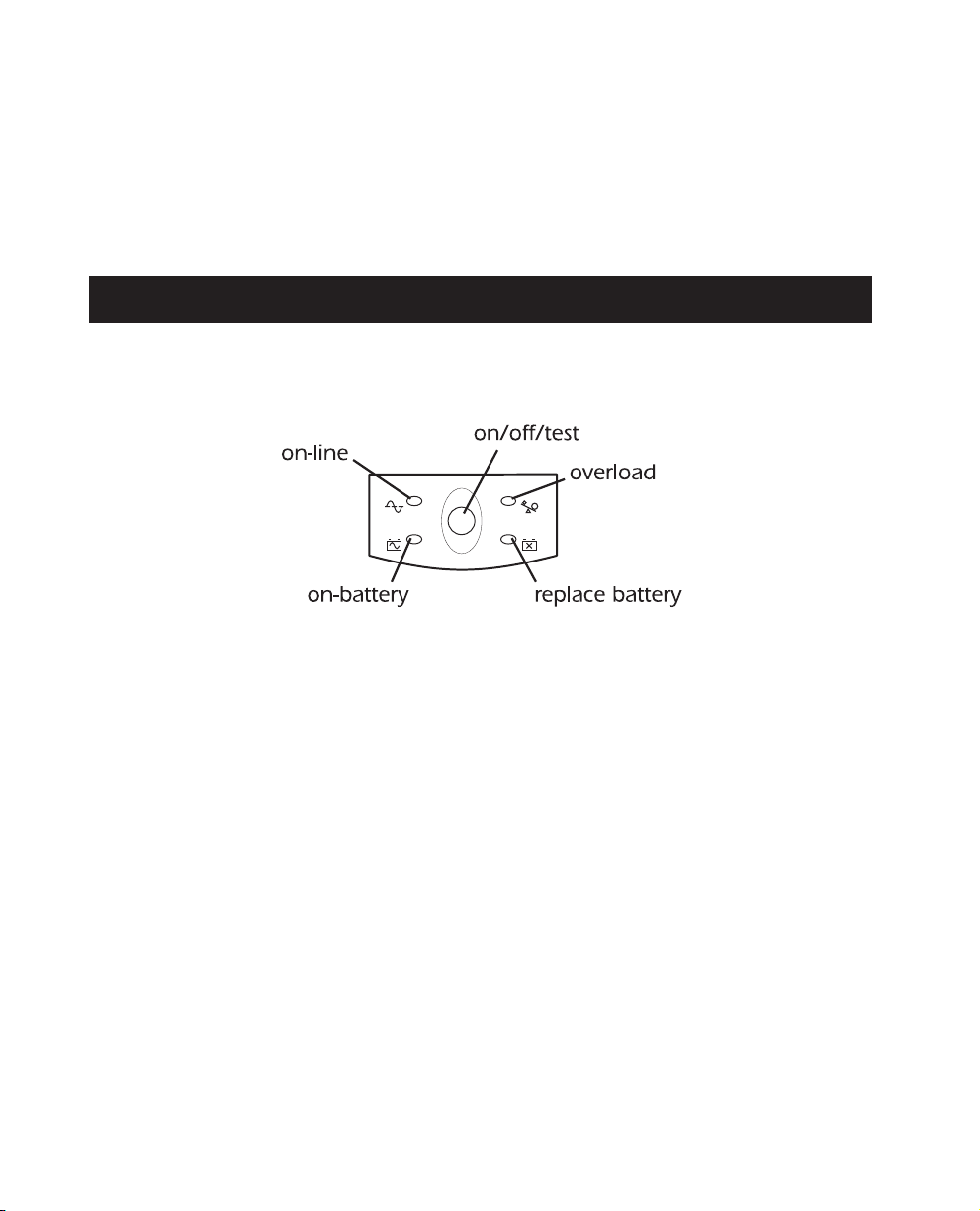
3.1 Front panel
Press the on/off/test button with the UPS plugged in to turn the UPS on or off. See Sec. 5.1.
On/off/test also activates the UPS’s self-test. See section 5.2.
The overload LED illuminates when the loads connected to the UPS exceed the UPS’s power capacity. See section 6.2.
The replace battery LED illuminates when the UPS’s battery is no longer useful and must be replaced. See section 10.
The on-battery LED illuminates when the UPS is supplying battery power to the loads.
The on-line LED means that filtered utility line is passing through the UPS to your equipment.
4
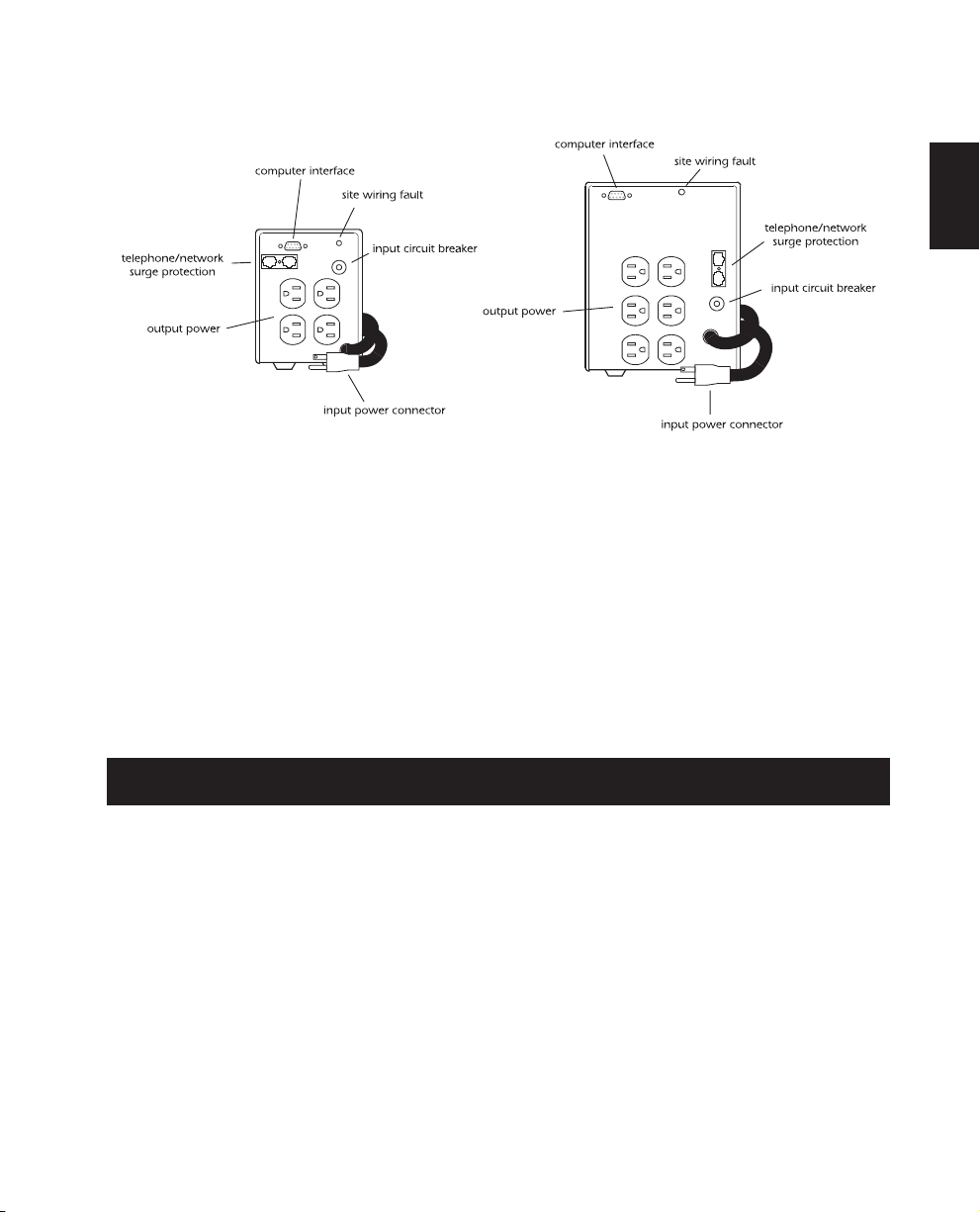
3.2 Rear Panel
420 and 650 VA 1000 and 1400 VA
The input power connector is a power cord with a NEMA 5-15P connector.
The output power receptacles are NEMA 5-15R type.
The RJ-45/RJ-11 modular combination is used for telephone/network surge protection with
single telephone lines and 10Base-T networks. See section 4.5.
The computer inter face port is for UPS monitoring and control. See section 4.4.
The site wiring fault indicator illuminates when the UPS is connected to an improperly wired
AC power outlet. See section 4.9.
The input circuit breaker trips when loads exceed the UPS’s capacity. The resettable center
plungers of the circuit breakers extend when tripped.
English
4. Installation
To obtain warranty coverage fill out and return the warranty registration card now.
4.1 Inspection
Inspect the UPS upon receipt. Notify the carrier and dealer if there is damage. The packaging is recyclable; save it for reuse or dispose of it properly.
5

4.2 Placement
Install the UPS in a protected area with adequate air flow the areas should be free of excessive
dust. Do not operate the UPS where the temperature and humidity is outside the specified limits.
See section 12. Allow the UPS to come to room temperature before continuing.
4.3 Protection Strategies
This UPS provides high performance power line protection to the loads. There are, however, other
potential entry points for damaging surges in information systems. These include serial ports (RS232, RS-422, RS-485, etc.), parallel ports, telephone lines, and LAN connections. These other entry
points must be considered in developing a comprehensive protection strategy for your system.
Contact your dealer or call the number in the front of this manual for information on related products designed to accomplish total system protection.
Sensitive information systems can be further safeguarded by following these guidelines:
n
Verify that all electrical outlets ar e properly grounded. See section 4.9.
n
Connect computer leads to a different electrical service branch than heavy motor loads like air
conditioners, copiers, refrigerators, and heavy industrial machinery.
n
Plug all power protection and computer equipment into outlets connected to the same service
branch (controlled by the same fuse or circuit breaker) where possible.
4.4 Connect Computer Interface (Optional)
Power management software and interface kits can be used with this UPS. Use only kits supplied
or approved by the manufacturer. If used, connect the interface cable to the 9-pin computer interface port on the back panel of the UPS. Secure the connector’s screws to complete the connection.
Note: Computer interface connection is optional. The UPS works properly without a computer interface connection.
4.5 Connect Telephone/Network Surge Suppression (Optional)
Connect a single line telephone or a 10Base-T network cable into the telephone/network surge
protection sockets on the back of the UPS. The RJ-45/RJ-11 modular combination sockets accept
all standard single line telephone and 10Base-T connections. This connection will require another
length of telephone cable (supplied) or network cabling (not supplied) to complete the connection. Note: This connection is optional. It is not needed to use the UPS.
6
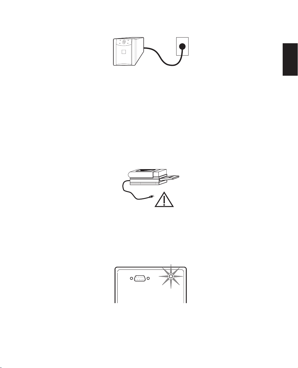
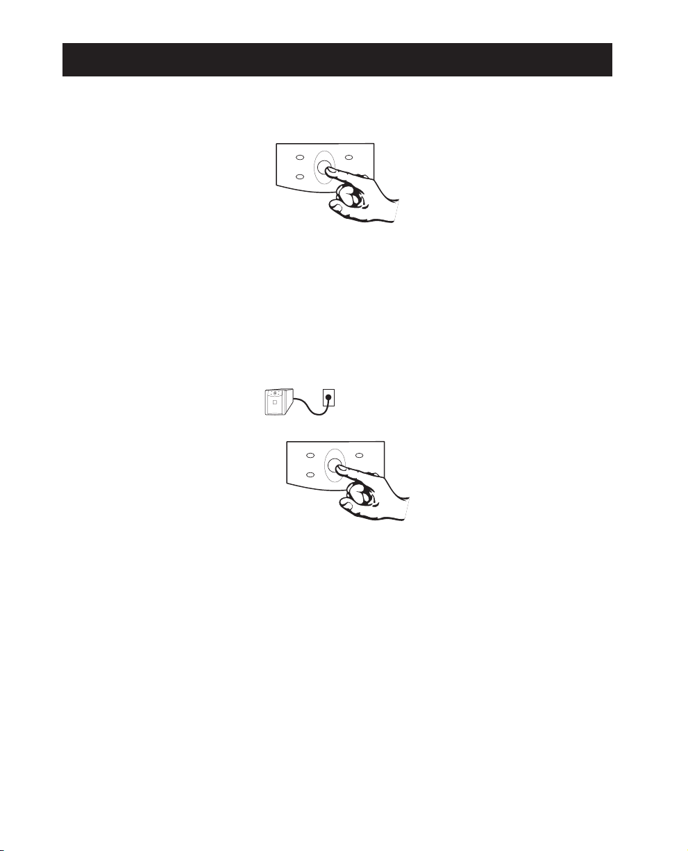
4.6 Connect to Utility
Plug the UPS into a two-pole, three-wire, grounded receptacle only. Avoid using extension cords
and adapter plugs.
4.7 Charge the battery
The UPS charges its battery whenever it is connected to utility power. For best results, charg e the
battery for 4 hours before use. It is acceptable to use the UPS without first charging the battery,
but on-battery run time may be reduced until the battery charges.
4.8 Connect the Loads
Plug the loads into the output connectors on the rear of the UPS. To use the UPS as a master on/
off switch, make sure that all of the loads are switched on.
English
Caution: Do not connect a laser printer to the UPS along with other computer equipment unless the UPS is
rated 1400 VA. A laser printer periodically draws significantly more power than when idle, and may overload
the UPS. Verify that the UPS can support the loads when the printer is in full operation (printing).
Test the system with all loads operating to make sure that the UPS is not overloaded. See section 6.2.
4.9 Check the Site Wiring Fault Indicator
After plugging in the loads and the UPS, check the site wiring fault indicator on the rear panel.
See section 3.2 for the location of the indicator on the back panel. It lights if the UPS is plugged
into an improperly wired AC power outlet. Wiring faults detected inc lude missing ground, hotneutral polarity reversal, and overloaded neutral circuit.
Caution: If the UPS indicates a site wiring fault, get a qualified electrician to correct the building
wiring.
7
5. Operation
5.1 Switch On — Switch Off
With the UPS plugged in, press the on/off/test button to supply power to the loads. The loads are
immediately powered while the UPS beeps and perfor ms a self-test. See section 5.2. Press the button again to turn off power to the loads. It may be convenient to use the UPS as a master on/off
switch for the protected equipment.
Note: The UPS is on (the internal processor is operating) whenever it is plugged in and utility voltage is present. Even when switched off the UPS maintains the battery charge.
5.2 Self-test
Use the self-test to verify both the operation of the UPS and the condition of the battery. With the
UPS plugged in to normal utility power and turned on, activate the self-test by pressing and hold-
ing the on/off/test button until the on-line LED flashes. This takes about 4 seconds.
Note: By default the UPS performs a self-test at power up and once every two weeks.
During the self-test, the UPS briefly operates the loads on-battery (the on-battery LED comes on).
If the UPS passes the self-test, it returns to on-line operation. The on-battery LED goes off and the
on-line LED displays a steady green indication.
If the UPS fails the self-test it immediately returns to on-line operation and lights the replace battery LED. The loads are not affected. Recharge the battery overnight and perform the self-test
again. If the replace battery LED is still on, see section 10 for information on replacing the battery.
5.3 Shutdown Mode
If there is no utility power present, external devices (e. g., servers) connected to the computer interface can command the UPS to shut down. This is normally done to preserve battery capacity
after the graceful shutdown of protected servers. In shutdown mode the UPS stops supplying
8

power to the load, waiting for the return of utility power. The UPS scrolls the front panel LED indicators sequentially in shutdown mode.
6. Alarms
6.1 On Battery
In on-battery operation, the on-battery LED illuminates and the UPS sounds an audible alarm consisting of one initial beep and four beeps every 30 seconds. The alarm stops when the UPS returns
to on-line operation.
6.2 Overload
When the UPS is overloaded (i. e., when the connected loads exceed maximum listed in section
12) the overload LED illuminates and the UPS emits a sustained tone. The alarm remains on until
the overload is removed. Disconnect nonessential load equipment from the UPS to eliminate the
overload.
6.3 Replace Battery
The UPS emits short beeps for one minute and the replace battery LED illuminates if the battery
fails the self-test. The UPS repeats the alarm every five hours. After one week the alar m becomes
continuous. Perform the self-test procedure in section 5.2 to confirm the replace battery condition.
The alarm stops when the battery passes the self-test.
English
6.4 Low Battery
On-battery, when the energy reserve of the battery runs low, the UPS beeps continuously until the
UPS shuts down from battery exhaustion or returns to on-line operation.
7. Options
7.1 Interface kits
For computer systems that have built-in UPS monitoring features, a series of interface kits are
available to connect the UPS to your system. Each kit includes the appropriate interface cable to
convert the UPS’s status signals into signals your system recognizes (use only factory supplied or
authorized UPS monitoring cables). See your dealer or call the number at the front of this manual
for more information.
9

7.2 Wall Mount Bracket
A special wall mount bracket is available for this UPS. See your dealer or call the number at the
front of this manual for more information.
8. Troubleshooting
Problem Possibl e Cause Solution
On/off/test bu tton not
pushed.
UPS input circuit breaker
UPS will not turn on.
UPS will not turn on or off.
UPS operates on-battery even
though normal line voltage is
thought to exist.
UPS beeps occasionally. Normal UPS operation.
UPS does not provide
expected back up time.
tripped.
Very low or no utility voltage.
Computer interface or
accessory problem.
UPS’s input circuit breaker
tripped.
The UPS’s battery is weak due
to recent outage or is near the
end of its service l ife.
Press the on/off/test button to power the UPS
and the load
Reduce the load on the UPS by unplugging
equipment and reset the circuit breaker by
pressing the plunger back in.
Check the AC power supply to the UPS with a
table lamp. If very dim or off, have the utility
voltage checked.
Disconnect the computer interface or accessory.
If the UPS now works normally, check the
interface cable, the attached computer, and the
accessory.
Reduce the load on the UPS by unplugging
equipment and reset the circuit breaker by
pushing the plunger back in.
None. The UPS is protecting the load.
Charge the battery. The UPS’s batteries require
recharging after an extended outage. Batteries age
faster when put into service often and when
operated at elevated temperatures. If the battery
is near the end of its service life, consider
replacing the battery even if the replace battery
indicator is not yet lit.
Front panel indicators flash
sequentially.
All indicators are illuminated
and the UPS emits a constant
tone.
The UPS operates normal ly,
but the site wiring fault
indicator is lit.
10
The UPS is overloaded.
The UPS has been shut down
by the UPS interface kit.
Internal UPS fault.
Building wiring error such as
missing ground or hot to
neutral wire reversal.
Unplug less needed equipment, such as printers.
None. The UPS will restart automaticall y when
utility power returns.
Do not attempt to use the UPS. Turn the UPS
off and have it serviced immediately.
Have a qualified electrician correct the building
wiring.

Problem Possible Cause Solution
All indicators are off and
the UPS is not operating.
The replace battery light is
illuminated.
The UPS is shut down and the
battery is discharged from an
extended power outage.
Weak batteries.
Replacement batteries not
connected properl y .
None. The UPS will return to normal operation
when the power is restored and the battery has a
sufficient charge.
Allow the batteries to recharge for at least four
hours. If the probl em persists after recharging,
replace the batteries. See section 10.
Confirm the battery connections. See section 10.
9. Service
If the UPS requires service:
1. Use the troubleshooting section (section to eliminate common problems.
2. Verify that no circuit breakers are tripped. A tripped circuit breaker is the most common UPS
problem! See section 6.2.
3. Go to section 5.2 and perform a self-test to check the battery.
4. If the problem persists, see the front of this manual for the correct telephone number and call
customer service. If customer service is not available in your area, call the dealer that sold the
UPS.
n Note the model number of the UPS, the serial number, and the date purchased. A techni-
cian will ask you to describe the problem and try to solve it over the phone, if possible.
If this is not possible the technician will issue an RMA#.
n If the UPS is under warranty, repairs are free. If not, there will be a charge for repair.
5. Pack the UPS in its original packaging. If the original packing is not available, ask customer
service about obtaining a new set.
n It is important to pack the UPS properly to avoid damage in transit. Never use styrofoam
beads for packaging. Dama ge sustained in transit is not covered under warranty.
n Include a letter with your name, RMA#, address, copy of the sales receipt, description of
the trouble, your daytime phone number, and a check (if necessary).
6. Mark the RMA# on the outside of the package. The factory cannot accept any package without
this marking.
7. Return the UPS by insured, prepaid carrier to the address at the front of this manual.
English
11

10. Replacing the Battery
This UPS has an easy to replace hot-swappable battery. Please read section 10.1 before performing
the procedure in sections 10.3 or 10.4.
10.1 Warning
n This Uninterruptible Power Source (UPS) contains potentially hazardous voltages. Do not at-
tempt to disassemble the unit beyond the battery replacement procedures below. Except for
the battery, the unit contains no user serviceable parts. Repairs are performed only by factory
trained service personnel.
n The batteries in this UPS are recyclable. Dispose of the batteries properly. The batteries con-
tain lead and pose a hazard to the environment and human health if not disposed of properly.
Refer to local codes for proper disposal requirements or return the battery to a factory authorized service center. See the instructions with the new battery for more information.
CAUTION—Do not dispose of batteries in a fire. The batteries may explode.
CAUTION—Do not open or mutilate batteries. They contain an electrolyte which is toxic and
harmful to the skin and eyes.
CAUTION—To avoid personal injury due to energy hazard, remove wrist watches and jewelr y
such as rings when replacing the batteries. Use tools with insulated handles.
CAUTION—Replace batteries with the same number and type of batteries as originally installed in
the UPS.
10.2 Replacement Batteries
See your dealer or call the number at the front of this manual for information on replacement battery kits.
12
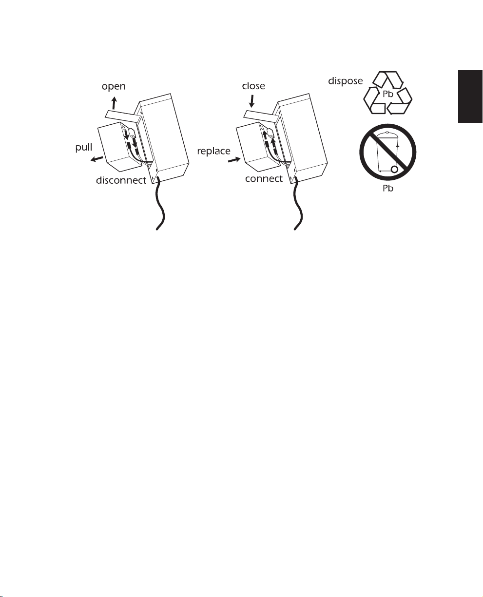
10.3 Battery Replacement Procedure (420 and 650 VA models)
Note: Please read the cautions in section 10.1.
Battery replacement is a safe procedure, isolated from electrical hazards. You may leave the UPS
and loads on for the following procedure.
1. Lay the UPS on its left side. Remove the two screws holding on the battery door and open the
door.
2. Gently pull out the battery by grasping the white tab.
3. Disconnect the two wires connecting the battery to the UPS. Loosen the wires by gently wiggling them while pulling straight back from the battery connector.
4. Connect the new battery in place of the old. Note: Small sparks at the battery connections
are normal during connection.
5. Replace the new battery in the UPS. Use care to avoid pinching the wires.
6. Close the battery compartment door and replace the screws.
7. Dispose of the old battery properly at an appropriate recycling facility or return it to the supplier in the packing material for the new battery. See the new battery instructions for more information.
English
13
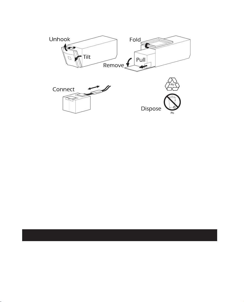
10.4 Battery Replacement Procedure (1000 and 1400 VA models)
Note: Please read the cautions in section 10.1.
Battery replacement is a safe procedure, isolated from electrical hazards. You may leave the UPS
and loads on for the following procedure.
1. Grasp the top of the front cover and tilt it out and down.
2. Unhook the bottom of the cover from the chassis and lift it upward to expose the battery
door. Be careful not to strain the ribbon cable. Do not touch the exposed printed circuit
board.
3. Fold the front cover on top of the UPS as shown.
4. Use a screwdriver or a coin to remove the two battery door screws and open the door.
5. Grasp the tab and gently pull the battery out of the UPS.
6. Disconnect the battery leads. Pull the two gray couplers apart to disconnect the battery.
7. Connect the battery leads to the new battery. Note: Small sparks at the battery connectors are
normal during battery connection.
8. Slide the battery into the UPS, close the battery door, replace the battery compartment screws,
and replace the front cover.
9. Dispose of the old battery properly at an appropriate recycling facility or return it to the supplier in the packing material for the new battery. See the new battery instructions for more information.
11. Storage
11.1 Storage conditions
Store the UPS covered and upright in a cool, dry location, with its battery fully charged. Before
storing, charge the UPS for at least 4 hours. Disconnect any cables connected to the computer interface port to avoid unnecessarily draining the battery.
14

11.2 Extended storage
During extended storage in environments where the ambient temperature is –15 to +30 °C
(+5 to +86 °F), charge the UPS’s battery every 6 months
During extended storage in environments where the ambient temperature is +30 to +45 °C
(+86 to +113 °F), charge the UPS’s battery every 3 months.
12. Specifications
420 VA 650 VA 1000 VA 1400 VA
Acceptable input voltage 0 — 160 VAC
Input voltage (on-line operation) 92-150 VAC
Output voltage 103-132 VAC
Nominal input frequency 50 or 60 Hz, autosensing
Input Protection Resettable circuit breaker
Frequency limits (on-line operation) 50 or 60 Hz, ±5%
Transfer time 2 ms typical , 4 ms maximum
Maximu m l oad 420 VA 280 W 650 VA 400 W 1000 VA 670 W 1400 VA 950 W
On-battery output vol tage 115 VAC
On- battery freque ncy 50 or 60 Hz, ±0.1 Hz; unless synchronized to utility during brownout.
On-battery waveshape Stepped sine-wave Trapezoid
English
Protection Overcurrent and short-circuit protected, latching shutdown on overload.
Surge energy rating (one time,
10/1000 µs waveform)
Surge current capability (one time,
8/20 µs waveform)
Surge response time
Surge voltage let-through (percentage
of applied ANSI C62.41 Cat. A ±6
kV test waveform)
Noise Filte r
Battery type Spill proof, maintenance free, user replaceable, sealed lead-acid
Typical battery life
Typic al recharge time 2 to 5 hours from total discharge
3 to 6 years, depending on number of discharge cycles and ambient
320 J 480 J
6500 A maximum
0 ns (instantaneous) normal mode;
<5 ns common mode
0.7% 0.3%
Normal and common mode EMI/RFI suppression,
100 kHz to 10 MHz
temperature
15

420 VA 650 VA 1000 VA 1400VA
Telephone line surge protection, 1.2 µs/50
waveform
Telephone line protection let through when
subjected to a 500A surge (8/20 µs
waveform, L-L, L-G)
10Base-T protection let through (from
6kV/125A normal mode surge)
Operating temperature 0 to +40 °C (+32 to +104 °F)
Storage temperature (see section 11) -15 to +45 °C (+5 to +113 °F)
Operating and storage relative humidity 0 to 95%, non-condensing
Operating elevation 0 to +3,000 m (0 to +10,000 ft)
Storage elevation 0 to +15,000 m (0 to +50,000 ft)
Electromagnetic immunity IEC 801-4 leve l IV, 801-5 level III
Audible noise at 1 m (3 ft) <45 dBA <50 dBA
Size (H x W x D)
Weight — net (shipping)
Safety and approvals UL 1778, UL 497A, CSA 107.1, FCC part 68, IEEE 802.3
EMC v e rification FCC/DOC Class B certified
16.8 x 11.9 x 36.1 cm
(6.6 x 4.6 x 14 in.)
7.9 (9.6) kg
17.5 (21.1) lb.
11.3 (12.2) kg
24.9 (26.8) lb.
±6kV
<5%
<1%
18.8 (21) kg
41.5 (46) lb.
21.6 x 17 x 43.9 cm
(8.5 x 6.7 x 17.3 in.)
24.1 (26.1) kg
53 (57.5) lb.
16
 Loading…
Каталог инструкций / Производители / APC / Smart-UPS 420VA/260W (SC420I), Electric Smart-UPS SC 620VA 230V, Electric Smart-UPS SC 420VA 230V, SC420I, SC620I
(скачивание инструкции бесплатно)
Формат файла: PDF
Доступность: Бесплатно как и все руководства на сайте. Без регистрации и SMS.
Дополнительно: Чтение инструкции онлайн
990-1853D 12/2005
Руководство
пользователя
Русский
APC Smart-UPS
®
SC
420/620
ВА
110/120/230
В
~
Источник
бесперебойного
питания
в
вертикальном
исполнении
Страница:
(1 из 14)
навигация

1

2

3

4

5

6

7

8

9

10

11

12

13

14
Оглавление инструкции
- Страница 1 из 15
Руководство пользователя Русский APC Smart-UPS® SC 420/620 ВА 110/120/230 В~ Источник бесперебойного питания в вертикальном исполнении 990-1853D 12/2005 - Страница 2 из 15
- Страница 3 из 15
Введение Источник бесперебойного питания (ИБП) компании APC обеспечивает защиту оборудования от перебоев в энергоснабжении, снижения напряжения в сети, кратковременного падения напряжения и скачков напряжения и тока. ИБП отфильтровывает помехи в сети электропитания и предохраняет оборудование от - Страница 4 из 15
2: ВВОД В ЭКСПЛУАТАЦИЮ Подключение аккумуляторной батареи n o Подсоедините черный провод к батарее. (Красный провод уже подсоединен.) Примечание: Незначительное искрение при подключении батареи является нормальным. Нижняя сторона устройства p q Подключение оборудования к ИБП Задние панели 110/120 - Страница 5 из 15
Подключение ИБП к локальной сети (если предусмотрено) Сетевые разъемы Последовательный порт Порты подавления выбросов в телефонной/ локальной сети Используйте только интерфейсные комплекты, рекомендуемые компанией APC. Для подключения к последовательному порту используйте только кабель из комплекта - Страница 6 из 15
3: ЭКСПЛУАТАЦИЯ Передняя панель управления 110/120 В 230 В ИНДИКАТОР ОПИСАНИЕ Питание от сети ИБП осуществляет подачу питания от сети к подключенному оборудованию. Питание от батареи ИБП осуществляет подачу питания от батареи к подключенному оборудованию. Перегрузка Подключенная нагрузка превышает - Страница 7 из 15
4: ПАРАМЕТРЫ, НАСТРАИВАЕМЫЕ ПОЛЬЗОВАТЕЛЕМ ПРИМЕЧАНИЕ: ПАРАМЕТРЫ НАСТРОЙКИ ИЗМЕНЯЮТСЯ ПРИ ПОМОЩИ ПРОГРАММНОГО ОБЕСПЕЧЕНИЯ POWERCHUTE BUSINESS EDITION ФУНКЦИЯ ЗНАЧЕНИЕ, ВОЗМОЖНЫЕ ЗАДАННОЕ ПО УМОЛЧАНИЮ ВАРИАНТЫ ЗНАЧЕНИЙ ОПИСАНИЕ Automatic Self-Test (Автоматическое самотестирование) Каждые 14 дней (336 - Страница 8 из 15
ПРИМЕЧАНИЕ: ПАРАМЕТРЫ НАСТРОЙКИ ИЗМЕНЯЮТСЯ ПРИ ПОМОЩИ ПРОГРАММНОГО ОБЕСПЕЧЕНИЯ POWERCHUTE BUSINESS EDITION ФУНКЦИЯ ЗНАЧЕНИЕ, ВОЗМОЖНЫЕ ЗАДАННОЕ ПО УМОЛЧАНИЮ ВАРИАНТЫ ЗНАЧЕНИЙ ОПИСАНИЕ Shutdown Delay (Задержка выключения системы) 60 секунд 60, 180, 300, 600 секунд Задайте продолжительность времени - Страница 9 из 15
5: ХРАНЕНИЕ И РЕЖИМ ТЕХНИЧЕСКОГО ОБСЛУЖИВАНИЯ Хранение Если Вы не используете ИБП, то накройте его и храните в сухом, прохладном месте с полностью заряженной батареей. При температуре от -15 до +30 °C заряжайте батарею ИБП каждые шесть месяцев. При температуре от +30 до +45 °C заряжайте батарею ИБП - Страница 10 из 15
6: ПОИСК И УСТРАНЕНИЕ НЕИСПРАВНОСТЕЙ, ТРАНСПОРТИРОВКА И ОБСЛУЖИВАНИЕ Следуйте рекомендациям, приведенным ниже в таблице, для устранения незначительных проблем, возникающих при монтаже и эксплуатации ИБП. Для получения помощи при возникновении сложных проблем с ИБП и для получения таблиц времени - Страница 11 из 15
ПРОБЛЕМА И/ИЛИ ЕЕ ВОЗМОЖНАЯ ПРИЧИНА РЕШЕНИЕ ГОРИТ СВЕТОДИОДНЫЙ ИНДИКАТОР ПЕРЕГРУЗКИ, ИБП ПОДАЕТ НЕПРЕРЫВНЫЙ ЗВУКОВОЙ СИГНАЛ ИБП перегружен. Подсоединенное оборудование потребляет мощность большую, чем может обеспечить ИБП. Нагрузка от подключенного оборудования превышает установленное максимально - Страница 12 из 15
Транспортировка и обслуживание Подготовьте источник бесперебойного питания для транспортировки: Выключите и отсоедините все оборудование, присоединенное к ИБП. Выключите ИБП и отсоедините его от розетки сети электропитания. Отсоедините батарею. В случае возникновения необходимости в ремонте ИБП не - Страница 13 из 15
7: СТАНДАРТЫ И ГАРАНТИЙНЫЕ ОБЯЗАТЕЛЬСТВА Модели на 110/120 В Настоящее оборудование прошло испытания, подтвердившие его соответствие ограничениям, предусмотренным требованиями раздела 15 правил Федеральной комиссии по связи (США) к цифровым устройствам класса А. Эти ограничения призваны - Страница 14 из 15
Ограниченная гарантия Компания American Power Conversion (APC) заявляет, что ее продукция не содержит дефектных материалов и не имеет производственных дефектов, и дает гарантию сроком на два года со дня приобретения. Обязательства компании по данной гарантии ограничены ремонтом и заменой любой - Страница 15 из 15
Инструкции и руководства похожие на APC Smart-UPS 420VA/260W (SC420I), Electric Smart-UPS SC 620VA 230V, Electric Smart-UPS SC 420VA 230V, SC420I, SC620I
Другие инструкции и руководства из категории источник бесперебойного питания (ИБП)
© 2023 manuals-help.ru, Все права защищены