- About
- Blog
- Projects
- Help
-
Donate
Donate icon
An illustration of a heart shape - Contact
- Jobs
- Volunteer
- People
Bookreader Item Preview
texts
GymnaUniphy Thermatur 200 Service manual
GymnaUniphy Thermatur 200 Service manual
- Addeddate
- 2020-05-19 18:47:37
- Classification
- Physical Therapy;Electrotherapy and Laser Therapy;GymnaUniphy Electrotherapy;GymnaUniphy Thermatur 200
- Identifier
- manual_GymnaUniphy_Thermatur_200_Service_manual
- Identifier-ark
- ark:/13960/t08x26451
- Ocr
- ABBYY FineReader 11.0 (Extended OCR)
- Page_number_confidence
- 89.29
- Ppi
- 300
- Scanner
- Internet Archive Python library 1.9.0
comment
Reviews
There are no reviews yet. Be the first one to
write a review.
SIMILAR ITEMS (based on metadata)
|
Service Instructions |
||
|
for the |
||
|
thermatur 200 |
||
|
Contents |
||
|
1. |
Construction ………………………………………………………………………………………….. |
3 |
|
1.1. |
Casing…………………………………………………………………………………………………….. |
3 |
|
1.2. |
Base group ……………………………………………………………………………………………… |
3 |
|
1.3. |
RF part……………………………………………………………………………………………………. |
3 |
|
1.4. |
Control desk…………………………………………………………………………………………….. |
3 |
|
1.5. |
Cable connections ……………………………………………………………………………………. |
3 |
|
2. |
Electrical and functional descriptions……………………………………………………… |
4 |
|
2.1. |
Description of the sub-assemblies………………………………………………………………. |
4 |
|
2.1.1. |
Power supply — sub-assembly A100 ……………………………………………………………. |
4 |
|
2.1.2. |
Power generator — sub-assembly A200 ……………………………………………………….. |
4 |
|
2.1.3. |
Harmonic filter — sub-assembly A500…………………………………………………………… |
4 |
|
2.1.4. |
Output circuit — sub-assembly A300…………………………………………………………….. |
4 |
|
2.1.5. |
Control computer — sub-assembly A400 ………………………………………………………. |
5 |
|
2.2. |
Description of the Overall Wiring Diagram……………………………………………………. |
6 |
|
3. |
Test ……………………………………………………………………………………………………….. |
7 |
|
3.1. |
Testing devices and measuring instruments ………………………………………………… |
7 |
|
3.2. |
Pre-test …………………………………………………………………………………………………… |
8 |
|
3.2.1. |
Check of earthing connections …………………………………………………………………… |
8 |
|
3.2.2. |
Check of the fuse elements ……………………………………………………………………….. |
8 |
|
3.2.3. |
High-voltage test………………………………………………………………………………………. |
8 |
|
3.3. |
Operation test ………………………………………………………………………………………….. |
8 |
|
3.3.1. |
Stand-by operation …………………………………………………………………………………… |
8 |
|
3.3.2. |
Modes of operation …………………………………………………………………………………… |
9 |
|
3.3.2.1. |
«MODE» and «APPLICATOR» keys……………………………………………………………… |
9 |
|
3.3.2.2. |
«+» and «-» keys, «MINUTES» indicator…………………………………………………………. |
9 |
|
3.3.2.3. |
Power selector «INTENSITY», indicators «WATTS» and «TUNING»………………….. |
9 |
|
3.3.2.4. |
Timer function ………………………………………………………………………………………… |
10 |
|
3.3.2.5. |
Emergency-off function……………………………………………………………………………. |
10 |
|
3.3.2.6. |
Reset key………………………………………………………………………………………………. |
10 |
|
3.4. |
Tuning…………………………………………………………………………………………………… |
10 |
|
3.5. |
Check of the operating voltages and currents …………………………………………….. |
11 |
|
3.6. |
Check of generator frequency and pulse parameters…………………………………… |
12 |
|
3.6.1. |
Generator frequency……………………………………………………………………………….. |
12 |
|
3.6.2. |
Pulsed operation of «70 Hz»……………………………………………………………………… |
12 |
|
3.6.3. |
Pulsed operation of «350 Hz»……………………………………………………………………. |
12 |
|
3.7. |
Check of the power output……………………………………………………………………….. |
12 |
|
3.7.1. |
Unbalanced output X003 …………………………………………………………………………. |
12 |
|
3.7.2. |
Balanced output X004/X005 …………………………………………………………………….. |
13 |
|
3.7.3. |
Auxiliary check of the power output …………………………………………………………… |
13 |
|
3.8. |
Check of the internal error recognition circuits ……………………………………………. |
13 |
|
3.8.1. |
Temperature monitoring circuit …………………………………………………………………. |
13 |
|
3.8.2. |
Generator voltage …………………………………………………………………………………… |
14 |
|
2 |
||
|
3.3.2.1 |
Exceeded voltage………………………………………………………………………………………. |
|
|
3.8.2.2 |
Less voltage …………………………………………………………………………………………….. |
. |
|
3.9. |
Continuous operation ……………………………………………………………………………… |
14 |
|
3.9.1. |
Preparation for continuous operation ………………………………………………………… |
14 |
|
3.9.2. |
Performance of the continuous operation ………………………………………………….. |
14 |
|
3.10. |
Final test……………………………………………………………………………………………….. |
15 |
|
3.10.1. |
High-voltage test ……………………………………………………………………………………. |
15 |
|
3.10.2. |
Measurement of the leakage current of the casing ……………………………………… |
15 |
|
3.10.3. |
Earthing conductor test …………………………………………………………………………… |
15 |
|
3.10.4. |
Measurement of the insulation resistance………………………………………………….. |
15 |
|
3.10.5. |
Measurement of the mains current consumption ………………………………………… |
16 |
|
3.10.6. |
Check of the power values ………………………………………………………………………. |
16 |
|
3.10.7. |
Operation check …………………………………………………………………………………….. |
16 |
|
4. |
Repair instructions……………………………………………………………………………….. |
16 |
|
4.1. |
Function check of the power generator A200……………………………………………… |
16 |
|
4.1.1. |
Check of the supply voltages …………………………………………………………………… |
16 |
|
4.1.2. |
Readiness for operation of the A200 sub-assembly…………………………………….. |
17 |
|
4.1.3. |
General information on the power loop ……………………………………………………… |
17 |
|
4.1.3.1. |
Level control ………………………………………………………………………………………….. |
17 |
|
4.1.3.2. |
Amplification tract …………………………………………………………………………………… |
17 |
|
4.1.3.3. |
Power and mismatching meter LFM………………………………………………………….. |
18 |
|
4.1.3.4. |
Adding amplifier……………………………………………………………………………………… |
18 |
|
4.1.3.5. |
Subtracting amplifier……………………………………………………………………………….. |
19 |
|
4.1.3.6. |
Multiplier (N202) …………………………………………………………………………………….. |
19 |
|
4.1.3.7. |
Setpoint/actual value comparator……………………………………………………………… |
19 |
|
4.1.3.8. |
Cable voltage monitoring circuit ……………………………………………………………….. |
19 |
|
4.1.3.9. |
Analogous OR interconnection…………………………………………………………………. |
20 |
|
4.1.4. |
Operation of the power supply …………………………………………………………………. |
20 |
|
4.1.5. |
Oscillator ………………………………………………………………………………………………. |
20 |
|
4.1.6. |
Driver……………………………………………………………………………………………………. |
20 |
|
4.1.7. |
RF circuits at the final stage output …………………………………………………………… |
21 |
|
4.1.8. |
Typical measurement values with a matched load (50 Ω)…………………………….. |
21 |
|
4.2. |
Repair instructions for the control computer (A400)…………………………………….. |
21 |
|
4.2.1. |
Indication of the error conditions ………………………………………………………………. |
21 |
|
4.2.2. |
Description of the control computer signals ……………………………………………….. |
22 |
|
4.3. |
Power supply (A100) ………………………………………………………………………………. |
24 |
|
4.4. |
Output circuit (A300) ………………………………………………………………………………. |
24 |
|
4.5. |
Harmonic filter (A500) …………………………………………………………………………….. |
24 |
|
5. |
Changes of the wiring conditions and components……………………………….. |
24 |
|
5.1 |
1. modification/supplement, state of 01.01.93 …………………………………………….. |
24 |
|
5.2 |
2. modification/supplement, state March 1995……………………………………………. |
25 |
|
5.3 |
3. modification/supplement, state of May 1996 …………………………………………… |
26 |
3
1.Construction
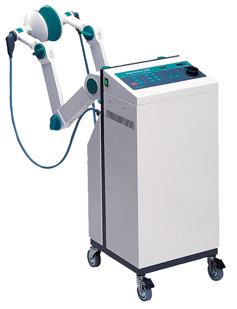
The short-wave therapy unit «thermatur 200» is a portable stand-type unit on guide rollers. As self-supporting sub-assembly the frame contains the base group on the one hand and the subassemblies RF part, control desk, rear and front walls on the other one.
1.1.Casing
Fig. 1 shows the exploded view of the unit. The face (1) can be taken off in front direction after loosening screws (7) and drawing off the earthing contact (12). Then, the rear wall (2) can be taken off after removing the screws, parts (10) by means of the patient socket wrench (cf. Spare Parts List) and drawing off the earthing contact (12). The mains input component A001 containing the fuse elements F001/F002 is screwed in the rear wall. For most service work it is only necessary to remove the face of the unit.
1.2.Base group
The elements of this sub-assembly are mounted on the bottom part of the frame. They include mains transformer (T001), power supply module (A100), mains filter (A002), power relay (K001) and earthing-conductor contact element (X001).
1.3.RF part
The RF part is subdivided into the following sub-assemblies: A200 — power generator
A500 — harmonic filter
A300 — output circuit.
The RF part is accommodated in an electromagnetically screened casing. After removing cover
(5) (Fig. 1) the sub-assemblies A200 (22) and A500 (16) as well as the components C001 and R002 (18), V001 and R001 (19), G001 (21) and thermistor R003 (24) (all in Fig. 2) are accessible. The sub-assembly A500 is electrically screened by cover (17) (Fig. 2). The external electric supply lines of the front compartment are connected to the lead-through filters or capacitors C002 to C007 and C016 to C019. The multipoint connector X002 (20) (Fig. 2), where the diode V002 is soldered at, is mounted below the front compartment. The fan motor M001 is accommodated on the cover plate of the RF part (Fig. 2). The rear compartment is closed by cover (11) (Fig. 1) and contains the sub-assembly A300 as well as the components X003 to X005, R004 and C009 to C015.
1.4.Control desk
The control desk (3) (Fig. 1) with the front foil (14) (Fig. 1) stuck up forms the upper part of the unit. The control computer PCB (printed circuit board) (A400) with its control and display components is mounted on spacers in the desk below the front foil. Both switches (S001) and S002) are arranged beneath that. The vertical adjustment of the control desk in the completely mounted unit can be performed after removing the caps (15) (Fig. 1) in the face of the casing.
1.5.Cable connections
The unit is to be connected to the mains via a removable, shielded power cord provided with a non-fused earthing contact. It is to be observed that the power cord, drawer of the combined element (A001) and the fuse elements in the drawer are suited for the corresponding voltage version of the unit (115 V or 230 V).
4
There are two cable harnesses in the unit. The primary cable harness is arranged at the left side of the mains connector (A001) and runs up to the mains switch (S001). The secondary one is at the right side and connects the sub-assembly A100, RF part and control computer A400 as the main parts. The casing parts control desk, face and rear walls are connected to the central earthing point X001 via earthing plug connections.
2.Electrical and functional descriptions
2.1.Description of the sub-assemblies
2.1.1.Power supply — sub-assembly A100
The A100 sub-assembly is a mains-frequency clocked switching power supply generating the V1 (+5 V), V2 (+15 V) and V3 (-15 V) supply voltages at output CON2. Through plug connector CON1 (terminals 1 and 3) the mains power is fed in; this connector is designed for 230 V as well as 115 V. It is a wide range input (90VAC to 265VAC) so that is not nessesary to switch over the sub-assemly for different mains voltages. The fine adjustment of the V2 supply voltage is to be performed by means of control P1.
2.1.2.Power generator — sub-assembly A200
This module can be subdivided into three main sections. The first one includes the crystalcontrolled generation, amplification and filtration of the 27.12-MHz high-frequency power. The second one of this sub-assembly includes the measurement and control circuits which enable an exact adjustment of the output power. And the third section contains the control circuit of the operating voltage of the amplifier.
Any repair work of this sub-assembly shall only be performed by the manufacturer. That’s why, this description is restricted mainly to the terminals. The supply power of the sub-assembly is fed via the plug connectors X206 (+15 V), X209 (-15 V) and X210 (earth). Additional supply terminals are X201 to X205 which are used for the regulation of the operating voltage of the output amplifier. There importance as well as that of the terminals X207, X208, X211 to X213 is described in detail in clause 2.2. The power is coupled out at the coaxial connector X222. This A200 sub-assembly is delivered in the tested and tuned condition. Only the fine adjustment of the output power is to be performed by means of R202 and adjustment of sero point at X216 by means of R205.
2.1.3.Harmonic filter — sub-assembly A500
A harmonic filter, that additionally attenuates the RF interference spectrum in the frequency range between 54 MHz and 100 MHz, is directly connected to the RF output of the power generator. It’s adjustment is necessary to ensure being below the interference levels given by law. In case of erroneous operation this sub-assembly has to be replaced in any case. Avoid any dismounting of the air-core chokes L501/L502. The cover on this sub-assembly is absolutely necessary to maintain the low RF interference values required by law.
2.1.4.Output circuit — sub-assembly A300
The output circuit is provided to match the application part, which is connected either to the coaxial output X003 or to the balanced output X004/X005, as exactly as possible to the generator. The matching is performed by means of the adjustable capacitor C302 driven by stepping motor M301, which is a component of a serial circuit in connection with the coils L302 and L303. The RF power is fed through connection X301. When using the capacitor-field electrodes (X004/X005) the contacts of relay K301 have the positions shown in the Overall
5
Wiring Diagram. The RF power flows via the capacitor chain C303 to C305 to the balance-to- unbalance transformer L301/L302/L303 whose secondary windings are parts of the serial circuit mentioned above.
When using the coil-field electrodes (X003) the relay is in the opposite switch position. Then, the signals flow from K301.1 via C302.1, C302.2, L302, C301 to the output socket X003 where the frequency-dependent components also form a serial circuit.
The chokes L304 and L305, the capacitors C306 to C308, C311 to C315 and the lead-through filters C009 to C015 ensure the decoupling of the control signals from the RF part. For the relay coil the diode V302 operates as free-wheeling diode, and transistor V301, in its common-base circuit, controls K301. Stepping motor and relay are triggered by control computer A400. R307 is the basic load for the control signal at X306.
2.1.5.Control computer — sub-assembly A400
Sub-assembly A400 is the central unit which realizes all signal and operation functions as well as measurement and control operations. The micro-controller 87C196KB, which reduces the computer hardware to a minimum and, thus, is a very service-friendly solution, is the basis of this control computer.
The integrated circuit 87C196KB contains clock generator, CPU, program memory, A/D converter, counter/timer and several different input and output ports. For clock generation (8 MHz) only the external components Q401, C406 and C406 are to be connected. After switching-on the watch-dog circuit D401 generates a reset signal and initiates a defined start of the internal program run of the processor. But the generation of the reset signal is also possible by means of key S409. The supply voltages +5 V, +15 V and -15 V are applied to the subassembly via X403. Mode of operation, applicator type and treatment time are adjusted by means of the key matrix S401 to S408 and S410 to S412. They are triggered by the output ports P1.4 to P1.7 and evaluated by the input ports P2.1 to P2.3 which are loaded by the pull-up resistors R449 to R451. The output power is adjusted by means of pulse generator D408 feeding the two direction-of-rotation dependent signals (2) and (4) to the processor via NMI and P0.5. Processor output P2.5/PWM delivers a pulse-duration modulated signal that is converted to a DC voltage by the two operational amplifier networks N401A/N401B and used to control the power output of generator A200. The connection C402-to-D402 (P0.6) is used to monitor the D/A conversion. In the pulsed modes of operation the DC voltage is keyed via processor output pin P4.7/AD15 and transistor T401. The generator control voltage, the level of which is also monitored by processor (P0.6), applies at plug connector X401.5. The bar indicator VD401 consists of ten LEDs and signals the degree of matching between patient circuit and generator output. The individual LEDs VD402 to VD410 have the following meaning:
VD402 signals the adjustment of the «Triplode» applicator.
VD403 signals the adjustment of the «Medium coil-field electrode» applicator. VD404 signals the adjustment of the «Small coil-field electrode» applicator. VD405 signals the adjustment of the «Large capacitor-field electrode» applicator.
VD406 signals the adjustment of the «Medium capacitor-field electrode» applicator. VD407 signals the adjustment of the «Small capacitor-field electrode» applicator. VD408 signals the adjustment of the «350-Hz» pulsed mode of operation.
VD409 signals the adjustment of the «70-Hz» pulsed mode of operation.
VD410 signals the adjustment of the «continuous-wave» (CW) mode of operation
6
The above information applies in multiplex form at the processor output pins P3.0/AD0 to P3.7/AD7 and is stored by the integrated circuits D404 to D406. This includes also the triggering of the piezo-signal transmitter B401 and signal D406(Q6) which is driven by D403 and, via its open-collector output, releases the switching-over of relay K301 via X402.5. Signal D406(Q5) is not used. The 7-segment indicators VD411 to VD415 are also triggered in the multiplex mode of operation. Data sources are the processor output pins P4.0/AD8 to P4.3/AD11 the hexadecimal data of which are decoded by integrated circuit D407. Amplified by T402 to T406 the multiplex signals P2.0/TXT and P1.0 to P1.3 are fed to the anodes of the indicator elements and show the following information:
VD411 shows the ten’s place of the minutes of treatment time.
VD412 shows the one’s place of the minutes of treatment time.
VD413 shows the hundred’s place of the unit’s output power.
VD414 shows the ten’s place of the unit’s output power.
VD415 shows the one’s place of the unit’s output power.
Integrated circuit D403 is used as driver circuit. In addition to the above signal it amplifies the motor control signals (M301) which are generated at D402 (P2.6 and P2.7). Both signals are directly amplified, inverted and transmitted to the plug connector X402 (pins 1 to 4). At each of it’s outputs, D403 has a free-wheeling diode and the other-end connectors «D» of which are connected to the +15-V supply voltage.
The switch condition of the emergency-off switch connected at plug connector X403.6 is evaluated by transistor T408 and terminal D402 (P2.4/T2RST) of the processor which signals this information for further processing. An emergency-off actuation additionally releases a switching operation of the transistors T409 and T407 where the collector of the last actuates the power relay K001 via X403.5.
Micro-controller 87C196KB has eight analogous inputs (P0.0 to P0.7). The directional coupler signals US+UD and US-UD, whose amounts are used for tuning the output circuit by means of M301, are connected to P0.0 and P0.1. At X401.3 there applies a signal that is proportional to the output power. Via the resistor network R465/R466 this arrives at pin P0.2 of the processor. R465 is provided for tuning the output power of the unit.
This circuit realizes two additional monitoring functions. A thermistor (R003) is provided at the heat sink of sub-assembly A200 for checking the temperature of this sub-assembly. It is connected to X401.4. R439 is a component of a voltage divider whose output value is measured at pin P0.3. The voltage across the power stage of sub-assembly A200 is monitored through the voltage divider R440/R441 whose feeding point is connected to X401.8.
The diodes V401 to V405 and capacitors C407 to C424 meet protective and RF interference protection functions.
2.2.Description of the Overall Wiring Diagram
The power supply of the thermatur 200 is realized by the mains transformer T001 and the A100 sub-assembly that is connected with the 115-V or 230-V, 50 HZ/60 Hz, mains via mains input A001, RF interference protection filter A002 and mains switch S001. The unit is adjusted to the corresponding mains voltage by the manufacturer. The 45-V output voltage of T001 is required for generating the supply voltage of the power stage of sub-assembly A200. The voltage is rectified by bridge G001 the positive pole of which is connected to X205. In the other DC path there is arranged thyristor V001 which is triggered by the operating voltage control circuit of sub-assembly A200 and charges capacitor C001 in dependence on the generator output power. This is synchronously performed to the mains frequency, where the 26-V voltage of T001
7
between X205 and X203 is used. The regulated DC voltage between X205 and X201 is superimposed by a serrated AC voltage of different amplitude and frequency. C001 is discharged via the R002 resistor. The supply voltage of the control circuit applies between X204 and X205.
The two DC voltages of +15 V (X206) and -15 V (X209), with their reference point X210, are required for the analogous circuits of sub-assembly A200 and pre-amplifier. They are prepared in the power supply module A100 (SK6.3 and SK6.4). The relay contact K001.1 which interrupts the supply of the pre-amplifier under emergency-off condition is connected in series with the positive signal path. The DC fan motor M001 is supplied with the negative voltage after a voltage reduction by diode V002. Capacitors and Filters C002 to C019 are applied for certain measures of the RF interference suppression.
A400 is fed via plug connector CON2 of sub-assembly A100. At CON2/5 the emergency-off switch is connected to +5 V and the power relay K001 to -15 V (CON2/1). When the -15-V circuit is interrupted the break contact opens and switches off the power of generator A200. The common reference point CON2/3 lies on the casing potential.
The remaining part of the circuit was already described in the above description of the subassembly. Finally, it is to be mentioned that with any service work particularly care is to be taken to the earthing connections given in the wiring diagram because they are decisive for maintaining the low RF interference suppression level.
3.Test
3.1.Testing devices and measuring instruments
—High-voltage testing equipment
—Leakage current measuring device
—Earthing-conductor testing device
—Insulation resistance measuring instrument
—Power meter URV 55
—Thermal Power Sensor NRV Z51
—Precision resistor 50 Ω, 200W, attenuation output 40dB
—Adjustable isolating transformer
—Digital multimeter FLUKE 87 /3 True RMS
—Moving-iron instrument (0.5 A, 10 A)
—Oscilloscope (50 MHz)
—Frequency meter (50 MHz)
—Stop-watch
—Resistance phantom circuit
—Compact lamp phantom LPH
—Diverse measuring lines and coaxial transitions
—Timer
8
3.2.Pre-test
—Remove the face of the unit.
—Remove the cover of the RF sub-assembly.
3.2.1. Check of earthing connections
— Visual inspection of the X001 connections to the unit’s rear wall and control desk. — Visual inspection of screw connections at the base and RF sub-assemblies.
3.2.2. Check of the fuse elements
—F001/F002 (combined element A001) — according to the voltage version:
230-V version: SP 6.3 A, fast (ceramic pipe, dim. 5 mm x 20 mm) 115-V version: FST 6.26 A, slow (glass pipe, dim. 6.3 mm x 32 mm).
—F003 (mains transformer T001) — FST100 mA, slow (glass pipe, dim. 5 mm x 20 mm).
—F1 (power supply A100) — FST 2 A, slow (glass pipe, dim. 5 mm x 20 mm).
3.2.3.High-voltage test
—Connect the power cord between unit socket and high-voltage testing equipment.
—Set mains switch S001 to position «I».
—For a short time apply the test voltage of 1.5 kV, 50 Hz, between earthing conductor and mains voltage connector of the unit to be tested.
3.3.Operation test
—Set mains switch S001 to position «0».
—Connect the unit to the rated mains voltage.
—Mains-voltage indicator in S001 shall not be lit.
3.3.1.Stand-by operation
—Switch on the unit by means of S001.
—All indicators will lit up, power indicator show the actual software version a short time
—Mains-voltage indicator in S001 shall be lit green (only with the 230-V version).
—Treatment time «MINUTES» (VD411/412) indicates «0».
—Power indicator «WATTS» (VD413 to 415) indicates «0».
—All other indicators are inactive.
9
3.3.2. Modes of operation
3.3.2.1. «MODE» and «APPLICATOR» keys
— Pressing one of the 9 keys (S402 to 404, 406 to 408, 410 to 412) activates the assigned LED.
— When changing between inductive and capacitive applicators the switching noise of relay K301 must sound.
3.3.2.2. «+» and «-» keys, «MINUTES» indicator
—A short actuation of the «+» key (S405) increments the treatment time indicator «MINUTES» by 1 (end value 30).
—Continuous actuation of the «+» key increases the indicated time in steps of 5 digits (e. g. 5, 10, 15, etc. — end value 30).
—The actuation of the «-» key (S401) has the similar effect but the time indicated is reset (end value 0).
—Simultaneous actuation of both keys results in the indication of «0».
3.3.2.3. Power selector «INTENSITY», indicators «WATTS» and «TUNING»
—Separate the coaxial plug connection X222 and connect the generator output to the t 50-Ω precision resistor with power meter
—Check the indication of the power ranges:
3 W to 30 W in 3-W steps, 30 W to 80 W in 5-W steps, 80 W to 200 W in 10-W steps
as well as the power range limits in dependence on the mode of operation and the applicator selected in the following way.
—Select «CW» mode, «Triplode» applicator and treatment time (> 0);
—Turn the power selector (D408) by one click-stop detent to the right side;
—«A» must appear on the «MINUTES» indicator for Tuning;
—After switching over the indicator to treatment time the power of «9 W» must be displayed, and all LEDs of the bar indicator (VD401) are activated;
—Check the power ranges by additional incrementing the power selector to the right;
—Then set the power to «0» by turning the power selector to the left side;
—Repeat this procedure in the CW mode of operation for all applicators
where the initial values after the tuning operation (9 W each) as well as the end values are to be checked:
|
coil-field electrode, small |
30 |
W |
|
coil-field electrode, medium |
90 |
W |
|
capacitor-field electrode, small |
21 |
W |
|
capacitor-field electrode, medium |
80 |
W |
|
capacitor-field electrode, large |
200 |
Q. |
—Subsequently check the limit values of the power ranges in the pulsed modes (initial values 3 W each), the end values are 30 W for all applicators except the capacitorfield electrode, small with 21 W.
 Loading…

Описание и характеристики
THERMATUR 200 – аппарат для непрерывной и импульсной коротковолновой (УВЧ) терапии (без аксессуаров).
Привлекательный дизайн аппарата, прочный и элегантный корпус, а также легкость в эксплуатации, обещает отличную интеграцию устройства в любой желаемой терапевтической области применения.
Метод лечения заключается в воздействии на организм электрическим полем ультравысокой частоты, которое подводится к пациенту посредством конденсаторных пластин (электродов).
Во время лечения импульсы чередуются с длинными паузам. Данный метод называют импульсной УВЧ – терапией.
Особенности
Показания к применению:
- воспалительные и гнойные заболевания
- заболевания периферической нервной системы,
- облитерирующий эндартериит
- полиомиелит
- прогрессирующая мышечная дистрофия,
- радикулит
- каузалгия
- длительно не заживающие раны и язвы
- отморожения I – III степеней
Характеристики
Мощный аппарат для термотерапии с высокочастотной энергией.
- Процедурный таймер электротерапии −1-60 мин; обновления: возможны через USB;
- управление через −12,1″ цветной дисплей;
- модули: импульсный и непрерывный;
- мощность: 0-490W / непрерывный пик, 0-1020W / импульсный пик;
- рабочая частота: 27.12МГц;
- предпрограммированные программы: да;
- бесплатные режимы: да;
- справочник: да;
- автоматический запуск: да;
- предупреждение о перегревании: да;
- импульс: 5, 10, 25, 50, 100, 200, 400, 600, 800;
- интервал импульса: 20, 40, 65,100, 200, 400
Размеры: 105×48х48 см
Вес: 40 кг.
|
Service Instructions |
||
|
for the |
||
|
thermatur 200 |
||
|
Contents |
||
|
1. |
Construction ………………………………………………………………………………………….. |
3 |
|
1.1. |
Casing…………………………………………………………………………………………………….. |
3 |
|
1.2. |
Base group ……………………………………………………………………………………………… |
3 |
|
1.3. |
RF part……………………………………………………………………………………………………. |
3 |
|
1.4. |
Control desk…………………………………………………………………………………………….. |
3 |
|
1.5. |
Cable connections ……………………………………………………………………………………. |
3 |
|
2. |
Electrical and functional descriptions……………………………………………………… |
4 |
|
2.1. |
Description of the sub-assemblies………………………………………………………………. |
4 |
|
2.1.1. |
Power supply — sub-assembly A100 ……………………………………………………………. |
4 |
|
2.1.2. |
Power generator — sub-assembly A200 ……………………………………………………….. |
4 |
|
2.1.3. |
Harmonic filter — sub-assembly A500…………………………………………………………… |
4 |
|
2.1.4. |
Output circuit — sub-assembly A300…………………………………………………………….. |
4 |
|
2.1.5. |
Control computer — sub-assembly A400 ………………………………………………………. |
5 |
|
2.2. |
Description of the Overall Wiring Diagram……………………………………………………. |
6 |
|
3. |
Test ……………………………………………………………………………………………………….. |
7 |
|
3.1. |
Testing devices and measuring instruments ………………………………………………… |
7 |
|
3.2. |
Pre-test …………………………………………………………………………………………………… |
8 |
|
3.2.1. |
Check of earthing connections …………………………………………………………………… |
8 |
|
3.2.2. |
Check of the fuse elements ……………………………………………………………………….. |
8 |
|
3.2.3. |
High-voltage test………………………………………………………………………………………. |
8 |
|
3.3. |
Operation test ………………………………………………………………………………………….. |
8 |
|
3.3.1. |
Stand-by operation …………………………………………………………………………………… |
8 |
|
3.3.2. |
Modes of operation …………………………………………………………………………………… |
9 |
|
3.3.2.1. |
«MODE» and «APPLICATOR» keys……………………………………………………………… |
9 |
|
3.3.2.2. |
«+» and «-» keys, «MINUTES» indicator…………………………………………………………. |
9 |
|
3.3.2.3. |
Power selector «INTENSITY», indicators «WATTS» and «TUNING»………………….. |
9 |
|
3.3.2.4. |
Timer function ………………………………………………………………………………………… |
10 |
|
3.3.2.5. |
Emergency-off function……………………………………………………………………………. |
10 |
|
3.3.2.6. |
Reset key………………………………………………………………………………………………. |
10 |
|
3.4. |
Tuning…………………………………………………………………………………………………… |
10 |
|
3.5. |
Check of the operating voltages and currents …………………………………………….. |
11 |
|
3.6. |
Check of generator frequency and pulse parameters…………………………………… |
12 |
|
3.6.1. |
Generator frequency……………………………………………………………………………….. |
12 |
|
3.6.2. |
Pulsed operation of «70 Hz»……………………………………………………………………… |
12 |
|
3.6.3. |
Pulsed operation of «350 Hz»……………………………………………………………………. |
12 |
|
3.7. |
Check of the power output……………………………………………………………………….. |
12 |
|
3.7.1. |
Unbalanced output X003 …………………………………………………………………………. |
12 |
|
3.7.2. |
Balanced output X004/X005 …………………………………………………………………….. |
13 |
|
3.7.3. |
Auxiliary check of the power output …………………………………………………………… |
13 |
|
3.8. |
Check of the internal error recognition circuits ……………………………………………. |
13 |
|
3.8.1. |
Temperature monitoring circuit …………………………………………………………………. |
13 |
|
3.8.2. |
Generator voltage …………………………………………………………………………………… |
14 |
|
2 |
||
|
3.3.2.1 |
Exceeded voltage………………………………………………………………………………………. |
|
|
3.8.2.2 |
Less voltage …………………………………………………………………………………………….. |
. |
|
3.9. |
Continuous operation ……………………………………………………………………………… |
14 |
|
3.9.1. |
Preparation for continuous operation ………………………………………………………… |
14 |
|
3.9.2. |
Performance of the continuous operation ………………………………………………….. |
14 |
|
3.10. |
Final test……………………………………………………………………………………………….. |
15 |
|
3.10.1. |
High-voltage test ……………………………………………………………………………………. |
15 |
|
3.10.2. |
Measurement of the leakage current of the casing ……………………………………… |
15 |
|
3.10.3. |
Earthing conductor test …………………………………………………………………………… |
15 |
|
3.10.4. |
Measurement of the insulation resistance………………………………………………….. |
15 |
|
3.10.5. |
Measurement of the mains current consumption ………………………………………… |
16 |
|
3.10.6. |
Check of the power values ………………………………………………………………………. |
16 |
|
3.10.7. |
Operation check …………………………………………………………………………………….. |
16 |
|
4. |
Repair instructions……………………………………………………………………………….. |
16 |
|
4.1. |
Function check of the power generator A200……………………………………………… |
16 |
|
4.1.1. |
Check of the supply voltages …………………………………………………………………… |
16 |
|
4.1.2. |
Readiness for operation of the A200 sub-assembly…………………………………….. |
17 |
|
4.1.3. |
General information on the power loop ……………………………………………………… |
17 |
|
4.1.3.1. |
Level control ………………………………………………………………………………………….. |
17 |
|
4.1.3.2. |
Amplification tract …………………………………………………………………………………… |
17 |
|
4.1.3.3. |
Power and mismatching meter LFM………………………………………………………….. |
18 |
|
4.1.3.4. |
Adding amplifier……………………………………………………………………………………… |
18 |
|
4.1.3.5. |
Subtracting amplifier……………………………………………………………………………….. |
19 |
|
4.1.3.6. |
Multiplier (N202) …………………………………………………………………………………….. |
19 |
|
4.1.3.7. |
Setpoint/actual value comparator……………………………………………………………… |
19 |
|
4.1.3.8. |
Cable voltage monitoring circuit ……………………………………………………………….. |
19 |
|
4.1.3.9. |
Analogous OR interconnection…………………………………………………………………. |
20 |
|
4.1.4. |
Operation of the power supply …………………………………………………………………. |
20 |
|
4.1.5. |
Oscillator ………………………………………………………………………………………………. |
20 |
|
4.1.6. |
Driver……………………………………………………………………………………………………. |
20 |
|
4.1.7. |
RF circuits at the final stage output …………………………………………………………… |
21 |
|
4.1.8. |
Typical measurement values with a matched load (50 Ω)…………………………….. |
21 |
|
4.2. |
Repair instructions for the control computer (A400)…………………………………….. |
21 |
|
4.2.1. |
Indication of the error conditions ………………………………………………………………. |
21 |
|
4.2.2. |
Description of the control computer signals ……………………………………………….. |
22 |
|
4.3. |
Power supply (A100) ………………………………………………………………………………. |
24 |
|
4.4. |
Output circuit (A300) ………………………………………………………………………………. |
24 |
|
4.5. |
Harmonic filter (A500) …………………………………………………………………………….. |
24 |
|
5. |
Changes of the wiring conditions and components……………………………….. |
24 |
|
5.1 |
1. modification/supplement, state of 01.01.93 …………………………………………….. |
24 |
|
5.2 |
2. modification/supplement, state March 1995……………………………………………. |
25 |
|
5.3 |
3. modification/supplement, state of May 1996 …………………………………………… |
26 |
3
1.Construction
The short-wave therapy unit «thermatur 200» is a portable stand-type unit on guide rollers. As self-supporting sub-assembly the frame contains the base group on the one hand and the subassemblies RF part, control desk, rear and front walls on the other one.
1.1.Casing
Fig. 1 shows the exploded view of the unit. The face (1) can be taken off in front direction after loosening screws (7) and drawing off the earthing contact (12). Then, the rear wall (2) can be taken off after removing the screws, parts (10) by means of the patient socket wrench (cf. Spare Parts List) and drawing off the earthing contact (12). The mains input component A001 containing the fuse elements F001/F002 is screwed in the rear wall. For most service work it is only necessary to remove the face of the unit.
1.2.Base group
The elements of this sub-assembly are mounted on the bottom part of the frame. They include mains transformer (T001), power supply module (A100), mains filter (A002), power relay (K001) and earthing-conductor contact element (X001).
1.3.RF part
The RF part is subdivided into the following sub-assemblies: A200 — power generator
A500 — harmonic filter
A300 — output circuit.
The RF part is accommodated in an electromagnetically screened casing. After removing cover
(5) (Fig. 1) the sub-assemblies A200 (22) and A500 (16) as well as the components C001 and R002 (18), V001 and R001 (19), G001 (21) and thermistor R003 (24) (all in Fig. 2) are accessible. The sub-assembly A500 is electrically screened by cover (17) (Fig. 2). The external electric supply lines of the front compartment are connected to the lead-through filters or capacitors C002 to C007 and C016 to C019. The multipoint connector X002 (20) (Fig. 2), where the diode V002 is soldered at, is mounted below the front compartment. The fan motor M001 is accommodated on the cover plate of the RF part (Fig. 2). The rear compartment is closed by cover (11) (Fig. 1) and contains the sub-assembly A300 as well as the components X003 to X005, R004 and C009 to C015.
1.4.Control desk
The control desk (3) (Fig. 1) with the front foil (14) (Fig. 1) stuck up forms the upper part of the unit. The control computer PCB (printed circuit board) (A400) with its control and display components is mounted on spacers in the desk below the front foil. Both switches (S001) and S002) are arranged beneath that. The vertical adjustment of the control desk in the completely mounted unit can be performed after removing the caps (15) (Fig. 1) in the face of the casing.
1.5.Cable connections
The unit is to be connected to the mains via a removable, shielded power cord provided with a non-fused earthing contact. It is to be observed that the power cord, drawer of the combined element (A001) and the fuse elements in the drawer are suited for the corresponding voltage version of the unit (115 V or 230 V).
4
There are two cable harnesses in the unit. The primary cable harness is arranged at the left side of the mains connector (A001) and runs up to the mains switch (S001). The secondary one is at the right side and connects the sub-assembly A100, RF part and control computer A400 as the main parts. The casing parts control desk, face and rear walls are connected to the central earthing point X001 via earthing plug connections.
2.Electrical and functional descriptions
2.1.Description of the sub-assemblies
2.1.1.Power supply — sub-assembly A100
The A100 sub-assembly is a mains-frequency clocked switching power supply generating the V1 (+5 V), V2 (+15 V) and V3 (-15 V) supply voltages at output CON2. Through plug connector CON1 (terminals 1 and 3) the mains power is fed in; this connector is designed for 230 V as well as 115 V. It is a wide range input (90VAC to 265VAC) so that is not nessesary to switch over the sub-assemly for different mains voltages. The fine adjustment of the V2 supply voltage is to be performed by means of control P1.
2.1.2.Power generator — sub-assembly A200
This module can be subdivided into three main sections. The first one includes the crystalcontrolled generation, amplification and filtration of the 27.12-MHz high-frequency power. The second one of this sub-assembly includes the measurement and control circuits which enable an exact adjustment of the output power. And the third section contains the control circuit of the operating voltage of the amplifier.
Any repair work of this sub-assembly shall only be performed by the manufacturer. That’s why, this description is restricted mainly to the terminals. The supply power of the sub-assembly is fed via the plug connectors X206 (+15 V), X209 (-15 V) and X210 (earth). Additional supply terminals are X201 to X205 which are used for the regulation of the operating voltage of the output amplifier. There importance as well as that of the terminals X207, X208, X211 to X213 is described in detail in clause 2.2. The power is coupled out at the coaxial connector X222. This A200 sub-assembly is delivered in the tested and tuned condition. Only the fine adjustment of the output power is to be performed by means of R202 and adjustment of sero point at X216 by means of R205.
2.1.3.Harmonic filter — sub-assembly A500
A harmonic filter, that additionally attenuates the RF interference spectrum in the frequency range between 54 MHz and 100 MHz, is directly connected to the RF output of the power generator. It’s adjustment is necessary to ensure being below the interference levels given by law. In case of erroneous operation this sub-assembly has to be replaced in any case. Avoid any dismounting of the air-core chokes L501/L502. The cover on this sub-assembly is absolutely necessary to maintain the low RF interference values required by law.
2.1.4.Output circuit — sub-assembly A300
The output circuit is provided to match the application part, which is connected either to the coaxial output X003 or to the balanced output X004/X005, as exactly as possible to the generator. The matching is performed by means of the adjustable capacitor C302 driven by stepping motor M301, which is a component of a serial circuit in connection with the coils L302 and L303. The RF power is fed through connection X301. When using the capacitor-field electrodes (X004/X005) the contacts of relay K301 have the positions shown in the Overall
5
Wiring Diagram. The RF power flows via the capacitor chain C303 to C305 to the balance-to- unbalance transformer L301/L302/L303 whose secondary windings are parts of the serial circuit mentioned above.
When using the coil-field electrodes (X003) the relay is in the opposite switch position. Then, the signals flow from K301.1 via C302.1, C302.2, L302, C301 to the output socket X003 where the frequency-dependent components also form a serial circuit.
The chokes L304 and L305, the capacitors C306 to C308, C311 to C315 and the lead-through filters C009 to C015 ensure the decoupling of the control signals from the RF part. For the relay coil the diode V302 operates as free-wheeling diode, and transistor V301, in its common-base circuit, controls K301. Stepping motor and relay are triggered by control computer A400. R307 is the basic load for the control signal at X306.
2.1.5.Control computer — sub-assembly A400
Sub-assembly A400 is the central unit which realizes all signal and operation functions as well as measurement and control operations. The micro-controller 87C196KB, which reduces the computer hardware to a minimum and, thus, is a very service-friendly solution, is the basis of this control computer.
The integrated circuit 87C196KB contains clock generator, CPU, program memory, A/D converter, counter/timer and several different input and output ports. For clock generation (8 MHz) only the external components Q401, C406 and C406 are to be connected. After switching-on the watch-dog circuit D401 generates a reset signal and initiates a defined start of the internal program run of the processor. But the generation of the reset signal is also possible by means of key S409. The supply voltages +5 V, +15 V and -15 V are applied to the subassembly via X403. Mode of operation, applicator type and treatment time are adjusted by means of the key matrix S401 to S408 and S410 to S412. They are triggered by the output ports P1.4 to P1.7 and evaluated by the input ports P2.1 to P2.3 which are loaded by the pull-up resistors R449 to R451. The output power is adjusted by means of pulse generator D408 feeding the two direction-of-rotation dependent signals (2) and (4) to the processor via NMI and P0.5. Processor output P2.5/PWM delivers a pulse-duration modulated signal that is converted to a DC voltage by the two operational amplifier networks N401A/N401B and used to control the power output of generator A200. The connection C402-to-D402 (P0.6) is used to monitor the D/A conversion. In the pulsed modes of operation the DC voltage is keyed via processor output pin P4.7/AD15 and transistor T401. The generator control voltage, the level of which is also monitored by processor (P0.6), applies at plug connector X401.5. The bar indicator VD401 consists of ten LEDs and signals the degree of matching between patient circuit and generator output. The individual LEDs VD402 to VD410 have the following meaning:
VD402 signals the adjustment of the «Triplode» applicator.
VD403 signals the adjustment of the «Medium coil-field electrode» applicator. VD404 signals the adjustment of the «Small coil-field electrode» applicator. VD405 signals the adjustment of the «Large capacitor-field electrode» applicator.
VD406 signals the adjustment of the «Medium capacitor-field electrode» applicator. VD407 signals the adjustment of the «Small capacitor-field electrode» applicator. VD408 signals the adjustment of the «350-Hz» pulsed mode of operation.
VD409 signals the adjustment of the «70-Hz» pulsed mode of operation.
VD410 signals the adjustment of the «continuous-wave» (CW) mode of operation
6
The above information applies in multiplex form at the processor output pins P3.0/AD0 to P3.7/AD7 and is stored by the integrated circuits D404 to D406. This includes also the triggering of the piezo-signal transmitter B401 and signal D406(Q6) which is driven by D403 and, via its open-collector output, releases the switching-over of relay K301 via X402.5. Signal D406(Q5) is not used. The 7-segment indicators VD411 to VD415 are also triggered in the multiplex mode of operation. Data sources are the processor output pins P4.0/AD8 to P4.3/AD11 the hexadecimal data of which are decoded by integrated circuit D407. Amplified by T402 to T406 the multiplex signals P2.0/TXT and P1.0 to P1.3 are fed to the anodes of the indicator elements and show the following information:
VD411 shows the ten’s place of the minutes of treatment time.
VD412 shows the one’s place of the minutes of treatment time.
VD413 shows the hundred’s place of the unit’s output power.
VD414 shows the ten’s place of the unit’s output power.
VD415 shows the one’s place of the unit’s output power.
Integrated circuit D403 is used as driver circuit. In addition to the above signal it amplifies the motor control signals (M301) which are generated at D402 (P2.6 and P2.7). Both signals are directly amplified, inverted and transmitted to the plug connector X402 (pins 1 to 4). At each of it’s outputs, D403 has a free-wheeling diode and the other-end connectors «D» of which are connected to the +15-V supply voltage.
The switch condition of the emergency-off switch connected at plug connector X403.6 is evaluated by transistor T408 and terminal D402 (P2.4/T2RST) of the processor which signals this information for further processing. An emergency-off actuation additionally releases a switching operation of the transistors T409 and T407 where the collector of the last actuates the power relay K001 via X403.5.
Micro-controller 87C196KB has eight analogous inputs (P0.0 to P0.7). The directional coupler signals US+UD and US-UD, whose amounts are used for tuning the output circuit by means of M301, are connected to P0.0 and P0.1. At X401.3 there applies a signal that is proportional to the output power. Via the resistor network R465/R466 this arrives at pin P0.2 of the processor. R465 is provided for tuning the output power of the unit.
This circuit realizes two additional monitoring functions. A thermistor (R003) is provided at the heat sink of sub-assembly A200 for checking the temperature of this sub-assembly. It is connected to X401.4. R439 is a component of a voltage divider whose output value is measured at pin P0.3. The voltage across the power stage of sub-assembly A200 is monitored through the voltage divider R440/R441 whose feeding point is connected to X401.8.
The diodes V401 to V405 and capacitors C407 to C424 meet protective and RF interference protection functions.
2.2.Description of the Overall Wiring Diagram
The power supply of the thermatur 200 is realized by the mains transformer T001 and the A100 sub-assembly that is connected with the 115-V or 230-V, 50 HZ/60 Hz, mains via mains input A001, RF interference protection filter A002 and mains switch S001. The unit is adjusted to the corresponding mains voltage by the manufacturer. The 45-V output voltage of T001 is required for generating the supply voltage of the power stage of sub-assembly A200. The voltage is rectified by bridge G001 the positive pole of which is connected to X205. In the other DC path there is arranged thyristor V001 which is triggered by the operating voltage control circuit of sub-assembly A200 and charges capacitor C001 in dependence on the generator output power. This is synchronously performed to the mains frequency, where the 26-V voltage of T001
7
between X205 and X203 is used. The regulated DC voltage between X205 and X201 is superimposed by a serrated AC voltage of different amplitude and frequency. C001 is discharged via the R002 resistor. The supply voltage of the control circuit applies between X204 and X205.
The two DC voltages of +15 V (X206) and -15 V (X209), with their reference point X210, are required for the analogous circuits of sub-assembly A200 and pre-amplifier. They are prepared in the power supply module A100 (SK6.3 and SK6.4). The relay contact K001.1 which interrupts the supply of the pre-amplifier under emergency-off condition is connected in series with the positive signal path. The DC fan motor M001 is supplied with the negative voltage after a voltage reduction by diode V002. Capacitors and Filters C002 to C019 are applied for certain measures of the RF interference suppression.
A400 is fed via plug connector CON2 of sub-assembly A100. At CON2/5 the emergency-off switch is connected to +5 V and the power relay K001 to -15 V (CON2/1). When the -15-V circuit is interrupted the break contact opens and switches off the power of generator A200. The common reference point CON2/3 lies on the casing potential.
The remaining part of the circuit was already described in the above description of the subassembly. Finally, it is to be mentioned that with any service work particularly care is to be taken to the earthing connections given in the wiring diagram because they are decisive for maintaining the low RF interference suppression level.
3.Test
3.1.Testing devices and measuring instruments
—High-voltage testing equipment
—Leakage current measuring device
—Earthing-conductor testing device
—Insulation resistance measuring instrument
—Power meter URV 55
—Thermal Power Sensor NRV Z51
—Precision resistor 50 Ω, 200W, attenuation output 40dB
—Adjustable isolating transformer
—Digital multimeter FLUKE 87 /3 True RMS
—Moving-iron instrument (0.5 A, 10 A)
—Oscilloscope (50 MHz)
—Frequency meter (50 MHz)
—Stop-watch
—Resistance phantom circuit
—Compact lamp phantom LPH
—Diverse measuring lines and coaxial transitions
—Timer
8
3.2.Pre-test
—Remove the face of the unit.
—Remove the cover of the RF sub-assembly.
3.2.1. Check of earthing connections
— Visual inspection of the X001 connections to the unit’s rear wall and control desk. — Visual inspection of screw connections at the base and RF sub-assemblies.
3.2.2. Check of the fuse elements
—F001/F002 (combined element A001) — according to the voltage version:
230-V version: SP 6.3 A, fast (ceramic pipe, dim. 5 mm x 20 mm) 115-V version: FST 6.26 A, slow (glass pipe, dim. 6.3 mm x 32 mm).
—F003 (mains transformer T001) — FST100 mA, slow (glass pipe, dim. 5 mm x 20 mm).
—F1 (power supply A100) — FST 2 A, slow (glass pipe, dim. 5 mm x 20 mm).
3.2.3.High-voltage test
—Connect the power cord between unit socket and high-voltage testing equipment.
—Set mains switch S001 to position «I».
—For a short time apply the test voltage of 1.5 kV, 50 Hz, between earthing conductor and mains voltage connector of the unit to be tested.
3.3.Operation test
—Set mains switch S001 to position «0».
—Connect the unit to the rated mains voltage.
—Mains-voltage indicator in S001 shall not be lit.
3.3.1.Stand-by operation
—Switch on the unit by means of S001.
—All indicators will lit up, power indicator show the actual software version a short time
—Mains-voltage indicator in S001 shall be lit green (only with the 230-V version).
—Treatment time «MINUTES» (VD411/412) indicates «0».
—Power indicator «WATTS» (VD413 to 415) indicates «0».
—All other indicators are inactive.
9
3.3.2. Modes of operation
3.3.2.1. «MODE» and «APPLICATOR» keys
— Pressing one of the 9 keys (S402 to 404, 406 to 408, 410 to 412) activates the assigned LED.
— When changing between inductive and capacitive applicators the switching noise of relay K301 must sound.
3.3.2.2. «+» and «-» keys, «MINUTES» indicator
—A short actuation of the «+» key (S405) increments the treatment time indicator «MINUTES» by 1 (end value 30).
—Continuous actuation of the «+» key increases the indicated time in steps of 5 digits (e. g. 5, 10, 15, etc. — end value 30).
—The actuation of the «-» key (S401) has the similar effect but the time indicated is reset (end value 0).
—Simultaneous actuation of both keys results in the indication of «0».
3.3.2.3. Power selector «INTENSITY», indicators «WATTS» and «TUNING»
—Separate the coaxial plug connection X222 and connect the generator output to the t 50-Ω precision resistor with power meter
—Check the indication of the power ranges:
3 W to 30 W in 3-W steps, 30 W to 80 W in 5-W steps, 80 W to 200 W in 10-W steps
as well as the power range limits in dependence on the mode of operation and the applicator selected in the following way.
—Select «CW» mode, «Triplode» applicator and treatment time (> 0);
—Turn the power selector (D408) by one click-stop detent to the right side;
—«A» must appear on the «MINUTES» indicator for Tuning;
—After switching over the indicator to treatment time the power of «9 W» must be displayed, and all LEDs of the bar indicator (VD401) are activated;
—Check the power ranges by additional incrementing the power selector to the right;
—Then set the power to «0» by turning the power selector to the left side;
—Repeat this procedure in the CW mode of operation for all applicators
where the initial values after the tuning operation (9 W each) as well as the end values are to be checked:
|
coil-field electrode, small |
30 |
W |
|
coil-field electrode, medium |
90 |
W |
|
capacitor-field electrode, small |
21 |
W |
|
capacitor-field electrode, medium |
80 |
W |
|
capacitor-field electrode, large |
200 |
Q. |
—Subsequently check the limit values of the power ranges in the pulsed modes (initial values 3 W each), the end values are 30 W for all applicators except the capacitorfield electrode, small with 21 W.
Терматур 200 – современные аппараты для коротковолновой терапии (УВЧ).
В ходе лечения достигается медицинский эффект в соответствии с заданными программой параметрами. Оборудование широко применяется при лечении воспалительных заболеваний, расстройств нервной системы.
Метод лечения заключается в воздействии на организм электрическим полем ультравысокой частоты, которое подводится к пациенту посредством конденсаторных пластин (электродов).
Во время лечения импульсы чередуются с длинными паузам. Данный метод называют импульсной УВЧ – терапией. Аппарат сочетает в себе исчерпывающую функциональность, эргономичный и привлекательный дизайн, удобный интерфейс, прочный и надежный корпус. Устройство обещает интеграцию устройства в любой желаемой терапевтической области применения. А компактные размеры позволят разместить его в любом физиотерапевтическом кабинете.
Цена предоставляется по запросу
Область применения:
- воспалительные и гнойные заболевания;
- заболевания периферической нервной системы;
- облитерирующий эндартериит;
- прогрессирующая мышечная дистрофия;
- радикулит;
- каузалгия;
- длительно не заживающие раны и язвы;
- обморожения I – III степеней.
В нашей компании Вы можете купить Терматур 200 в Москве с оперативной доставкой в следующие регионы: Москва, Санкт-Петербург, Ростов-на-Дону, Краснодар, Новосибирск, Нижний Новгород, Челябинск. Нашей компанией предлагается самая выгодная цена, комфортные условия оплаты. Гарантирован индивидуальный подход к каждому и профессиональная помощь в выборе оснащения для медкабинетов, центров реабилитации.
Технические характеристики:
| Электропитание | 230 ВАТ, 50/60 Гц |
| Потребляемая мощность | 700 ВАТ |
| Процедурный таймер электротерапии | 0-60 мин |
| Процедурный таймер | 0 – 30 мин |
| Выходная пиковая мощность | 400 Вт |
| Выходная мощность в непрерывном режиме | 3– 200 Вт |
| Выходная мощность в импульсном режиме | 30 Вт |
| Частота излучения | 27,12 МГц |
| Частота пульсаций в импульсном режиме | 70 – 350 Гц |
| Время импульса | 2 мc / 0,4мc |
| Запуск | автоматический |
| Размеры (ДхШхВ) | 380 x 380 x 850 мм |
| Вес | 40 кг. |
Цена предоставляется по запросу
Смотрите также

МЦ «Он Клиник»

9 ЛДЦ Минобороны России

ФГУ Военный санаторий «Десантник» Воздушно-десантных войск

Водолечебница. Центральная поликлиника МВД Российской Федерации

Санаторий «Жемчужина Урала»

SPA Курорт «Лаго-Наки»

МЦ «Медси»

Санаторий-Профилакторий «Сибиряк»

ЛДС «Витязь»

ФГУ Центр реабилитации ФСС РФ «Топаз»

МЦ «Мать и Дитя»

ФГУ «Пятигорский центральный военный санаторий» МО РФ

Санаторий «Спутник»