- Manuals
- Brands
- Siemens Manuals
- Medical Equipment
- ACUSON X300
- User and reference manual
-
Contents
-
Table of Contents
-
Bookmarks
Quick Links
ACUSON X300
ACUSON X300 PE
ACUSON X150
Supplement to the User and Reference Manuals
S i e m e n s M e d i c a l S o l u t i o n s U S A, I n c .
10658982-02
Related Manuals for Siemens ACUSON X300
Summary of Contents for Siemens ACUSON X300
-
Page 1
ACUSON X300 ACUSON X300 PE ACUSON X150 Supplement to the User and Reference Manuals S i e m e n s M e d i c a l S o l u t i o n s U S A, I n c . -
Page 2
Printed in the Republic of Korea. Directive 93/42/EEC of June 14, 1993 concerning Medical Devices. The CE marking only applies to ACUSON is a trademark of Siemens Medical Solutions medical devices that have been put on the market USA, Inc. -
Page 3: Table Of Contents
Contents Supplement to the User and Reference Manuals……….4 About this Supplement ……………… 4 Compatible Systems and Product Versions ……….. 4 Wireless Network Connections …………….. 5 Approved Wireless Adapters …………….. 5 Connecting the Wireless Adapter to the System ……….. 6 Informational Icons for the Wireless Adapter……….
-
Page 4: Supplement To The User And Reference Manuals
This supplement provides new information about features, accessories, settings, and standards. Refer to the user and reference manuals for a complete set of operating instructions for your ultrasound system. Compatible Systems and Product Versions ACUSON X300 PE (7.5) ACUSON X300 (2.5) SONOVISTA X300 (2.5, 7.5) …
-
Page 5: Wireless Network Connections
5 GHz frequency bandwidth to reduce potential radio interference from the 2.4 GHz frequency bandwidth. Approved Wireless Adapters Caution: Use of wireless adapters not tested for use and approved by Siemens can damage the ultrasound system. Do not connect any wireless adapters to the system except the wireless adapters listed below.
-
Page 6: Connecting The Wireless Adapter To The System
RF energy sources. To prevent this interference, increase the distance between the ultrasound system and the interfering RF energy source. Siemens recommends connecting the wireless adapter to the leftmost USB port on the Input/Output panel of the ultrasound system. Informational Icons for the Wireless Adapter…
-
Page 7: Wireless Network Selections (System Configuration)
Wireless Network Selections (System Configuration) (Supplement to System Configuration, Chapter 1, System Reference) Use the system presets to enable and disable a wireless network adapter connected to the ultrasound system. You can require a password to prevent unauthorized changes to the wireless network selections.
-
Page 8: Network Profile Settings
Network Profile Settings Wireless > Network Settings > New Wireless > Network Settings > Edit Selection Option(s) Allows you to… Network Name (text entry) Enter the name of a wireless network. (SSID) Non-broadcast on, off Configure the network profile for a wireless network that network broadcasts its name (off) or does not broadcast its name (on).
-
Page 9: Internet Protocol Properties
Internet Protocol Properties Wireless > Connection Information > Properties Selection Option(s) Allows you to… Obtain an IP address automatically (DHCP) on, off Configure the ultrasound system to use dynamic IP addresses assigned by a DHCP (Dynamic Host Configuration Protocol) server (on) or to use a static IP (Internet Protocol) address (off).
-
Page 10: Configuring A Connection To A Wireless Network
Access the system presets. Select Wireless. Enter a password, if required. Do This: Activate a connection to a wireless Note: Siemens recommends using secured networks to ensure data security. network Select Enabled. Deactivate the connection to a Select Disabled.
-
Page 11: Ultrasound System Security (Virus Protection)
Ultrasound System Security (Virus Protection) Ultrasound System Security is virus protection software that Siemens recommends for ultrasound systems connected to a LAN or wireless network. To enable Ultrasound System Security, contact your Siemens service representative.
-
Page 12: Viewing Patient Reports With Qview
1. Press Report. The system displays the patient report using the layout provided by Qview. 2. Press Report to exit the report page. Or, for the ACUSON X300 PE system and the ACUSON X150 system, press the Exit soft key.
-
Page 13: Report Option — Configuration Selections
Report Option — Configuration Selections Report Option Selection Option(s) Allows you to… Report Type System Report Only Select the layout the ultrasound system uses to display Telexy (Qview) Only patient reports. Both System Report Only enables only the layout provided by the ultrasound system.
-
Page 14: Quickstart Battery-Powered Standby Mode
QuickStart Battery-Powered Standby Mode (Available only on the ACUSON X300 PE 7.5 system) (Supplement to QuickStart Feature (Battery-Powered Standby Mode), System Setup, Chapter 3, Instructions for Use) The QuickStart battery pack charges whenever the ultrasound system is connected to a power outlet, including when the system is powered on, powered off, or in standby mode.
-
Page 15: Updates To The System Controls
Do This Display or hide the Press the toggle switch on the handle of the transducer. reference line indicating the intersection of the sagittal and transverse planes on each image Reposition the sagittal Press the STEER control on the control panel. image during live dual format Example of live dual format before the sagittal image is repositioned.
-
Page 16: Needle Guide Brackets
Needle Guide Brackets (Supplement to Safety and Care, Chapter 2, Instructions for Use and Transducer Accessories and Biopsy, Chapter 5, Instructions for Use) BP9-4 Disposable Endocavity Biopsy Straight Needle Guide Kit 1 The disposable endocavity needle guide is a single-use item. Refer to the in-box instructions for attachment and care procedures, including cleaning, sterilization, and disposal.
-
Page 17: Tissue Harmonic Imaging (Thi) Frequencies
Tissue Harmonic Imaging (THI) Frequencies (Available only on the ACUSON X300 PE 7.5 system) (Replaces the frequency settings for only the following three transducers for THI, Imaging Functions, Technical Description, Appendix A, Instructions for Use; the frequencies for other compatible transducers are unchanged) …
-
Page 18: Standards Compliance
Standards Compliance (For ACUSON X300 PE 7.5: replaces the Standards Compliance, Technical Description, Appendix A, Instructions for Use; the Acoustic Output Standards and CE Declaration are unchanged.) (For ACUSON X300 2.5: replaces the Standards Compliance, Technical Description, Chapter 6, [1] Instructions for Use; the Acoustic Output Standards and CE Declaration are unchanged.)
Компактность, эффективность и исключительное качество
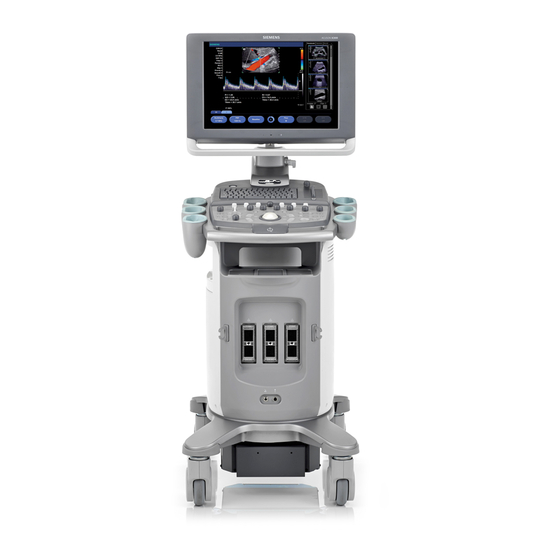
Новая компактная и портативная ультразвуковая система ACUSON X300™ обеспечивает исключительную визуализацию. В условиях ограниченного пространства или необходимости в постоянном перемещении эта полнофункциональная система позволит справиться с самыми сложными клиническими задачами.
Эффективность клинического применения. Система X300 обладает богатым набором функций, рассчитанным на универсальное применение для решения самых разных клинических задач.
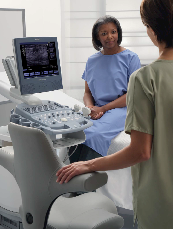
Беспрецедентная эффективность благодаря удобной и комфортной системе X300 на базе конструкции ErgoDynamic™.
Превосходное качество изображений и передовые технологии, а также широкая линейка совместимых датчиков для выполнения разнообразных исследований и точной диагностики.
Решения для обслуживания заказчиков в реальном времени – дистанционное обслуживание для максимальной производительности и бесперебойной работы.
- About
- Blog
- Projects
- Help
-
Donate
Donate icon
An illustration of a heart shape - Contact
- Jobs
- Volunteer
- People
Bookreader Item Preview
texts
Siemens Acuson X300 Operator Manual
Siemens Acuson X300 Operator Manual
- Addeddate
- 2020-05-20 05:46:36
- Classification
- Medical Imaging;Ultrasound;Siemens Ultrasound;Siemens Acuson X300
- Identifier
- manual_Siemens_Acuson_X300_Operator_Manual
- Identifier-ark
- ark:/13960/t48q4ss7b
- Ocr
- ABBYY FineReader 11.0 (Extended OCR)
- Page_number_confidence
- 95.33
- Ppi
- 300
- Scanner
- Internet Archive Python library 1.9.0
comment
Reviews
There are no reviews yet. Be the first one to
write a review.
SIMILAR ITEMS (based on metadata)
![]()
ACUSON X300 Ultrasound Imaging System
Instructions for Use
<![if ! IE]>
<![endif]>01-01-001-VFT-10348702
|
Siemens Medical Solutions USA, Inc. |
10348702 REV 01 |

Software Version 3
Siemens Medical Solutions USA, Inc. Ultrasound Division
1230 Shorebird Way
Mountain View, CA 94043-1344 U.S.A.
(800) 498-7948
(650) 969-9112
©2008 Siemens Medical Solutions USA, Inc. All Rights Reserved.
February 2008
Printed in the Republic of Korea.
Siemens ACUSON X300, THI, MultiHertz, DIMAQ, microCase, QuickSet, SuppleFlex, Evolve Package, SynAps, TGO, DTI, 3-Scape, Axius, Clarify, SieClear, SieScape, Velocity Vector Imaging, AcuNav, and SwiftLink are trademarks or registered trademarks of Siemens AG or its subsidiaries and affiliates.
Windows, CIDEX, CIDEX Plus, CIDEX OPA, Milton, Virkon, STERRAD and Gigasept FF are registered trademarks of their respective owners.
Siemens reserves the right to change system specifications at any time.
CE Declaration
This product is provided with a CE marking in accordance with the regulations stated in Council Directive 93/42/EEC of June 14, 1993 concerning Medical Devices. Siemens Medical Solutions USA, Inc. is certified by Notified Body 0123 to Annex II.3 – Full Quality System.
Authorized EC Representative: Siemens Aktiengesellschaft Medical Solutions Henkestraße 127
D-91052 Erlangen Germany

Contents
|
Chapter 1 |
Introduction |
|
General overview of the diagnostic ultrasound imaging system. |
|
|
Chapter 2 |
Safety and Care |
|
Detailed information on system safety and how to care for and maintain the |
|
|
system, transducers, and transducer accessories. |
|
|
Chapter 3 |
System Setup |
|
Detailed descriptions of how to transport, set up, and prepare the system for use, |
|
|
including transducer connection and system startup procedures. |
|
|
Chapter 4 |
Examination Fundamentals |
|
Information on starting an examination, including instructions for entering and |
|
|
editing patient data and selecting an exam type, imaging mode, and transducer. |
|
|
Chapter 5 |
Transducer Accessories and Biopsy |
|
Attachment procedures for transducer accessories and an explanation of the |
|
|
biopsy (puncture) function, including a procedure for needle path verification. |
|
|
Chapter 6 |
Transesophageal Transducer |
|
Description of the transesophageal transducer, including cleaning and care |
|
|
information for the transducer. |
|
|
Appendix A |
Technical Description |
|
Technical description of the ultrasound system. |
|
|
Appendix B |
Control Panel |
|
Explanation of all controls and keys on the control panel, alphanumeric keyboard, |
|
|
and optional footswitch. |
|
|
Appendix C |
On-screen Controls |
|
Explanation of all on-screen controls, including menus and soft key selections. |
|
|
Appendix D |
Acoustic Output Reference |
|
Acoustic output reporting tables. |
Note: Not all features and options described in this publication are available to all users. Please check with your Siemens representative to determine the current availability of features and options.
I N S T R U C T I O N S F O R U S E
i

ii
I N S T R U C T I O N S F O R U S E

About the User and Reference Manuals
The user and reference manuals consist of the following publications.
|
Publication |
Includes |
|
|
Instructions for Use |
Technical description of the ultrasound system |
|
|
Safety and care information for the system and compatible transducers |
||
|
Descriptions of all system controls |
||
|
Procedures for system setup, examination fundamentals, and the biopsy |
||
|
function |
||
|
Acoustic output data |
||
|
Features and Applications |
Descriptions of image acquisition and optimization, including optional imaging |
|
|
Reference* |
features |
|
|
General and exam-specific measurements and calculations |
||
|
Data management |
||
|
Explanation of the clinical software programs for use on the ultrasound system |
||
|
System Reference* |
Description of customizable system settings |
|
|
Information about DICOM connectivity, network capabilities, and external |
||
|
devices |
||
|
Clinical references |
||
|
Electromagnetic Emissions and |
Information regarding the electromagnetic compatibility (EMC) testing of this |
|
|
Immunity: Guidance and |
system |
|
|
Manufacturer’s Declaration* |
*Languages supported by the user interface include a translation of this publication.
I N S T R U C T I O N S F O R U S E
iii

Conventions
Take a moment to familiarize yourself with these conventions.
|
Warnings, Cautions, and Notes |
WARNING: Warnings are intended to alert you to the importance of |
||
|
following the correct operating procedures where risk of injury to the patient |
|||
|
or system user exists. |
|||
|
Caution: Cautions are intended to alert you to the importance of following |
|||
|
correct operating procedures to prevent the risk of damage to the system. |
|||
|
Note: Notes contain information concerning the proper use of the system and/or |
|||
|
correct execution of a procedure. |
|||
|
Cross-References |
Examples: |
||
|
See also: Biohazards, Safety and Care, Chapter 2, Instructions for Use |
|||
|
See also: Documentation Devices, Chapter 2, System Reference |
|||
|
See also: Alphanumeric Keyboard, p. 26 |
|||
|
Customizable System Settings |
System settings available for customization are depicted as shown. |
||
|
Example: |
|||
|
Default Settings > Automatic Freeze Response |
|||
|
Keys and Controls |
Keys and controls located on the control panel are identified by uppercase, |
||
|
boldface type. |
|||
|
Example: |
|||
|
Rotate the 2D control. |
|||
|
Keys located on the keyboard are identified by boldface type. |
|||
|
Example: |
|||
|
Press the Exam key. |
|||
|
On-screen Objects |
On-screen objects such as menu selections, soft key selections, and buttons are |
||
|
identified by boldface type. |
|||
|
Example: |
|||
|
The system displays the Patient Registration form. |
|||
|
Selection of On-screen Objects |
The SET key on the control panel functions as a point-and-select device (similar |
||
|
to a computer mouse) when used with the trackball. |
|||
|
«Select» or «click» describes this action: |
|||
|
Roll the trackball to position the pointer (cursor) on an on-screen object and then |
|||
|
press the SET key. |
|||
|
«Drag» describes this action: |
|||
|
Roll the trackball to position the pointer (cursor) on an on-screen object and then |
|||
|
press and hold the SET key. Roll the trackball to reposition the object and then |
|||
|
release the SET key. |
iv
I N S T R U C T I O N S F O R U S E

1 Introduction
|
System Overview …………………………………………………………………………………… |
3 |
|
System Review…………………………………………………………………………………. |
4 |
|
Intended Use …………………………………………………………………………………………. |
6 |
|
Transducers and Intended Applications………………………………………………… |
7 |
|
Image Screen Layout……………………………………………………………………………… |
8 |
|
Screen Saver……………………………………………………………………………………. |
8 |
|
Sample Image Screen ……………………………………………………………………….. |
9 |
|
Status Bar………………………………………………………………………………… |
10 |
|
User-Defined System Settings………………………………………………………………. |
10 |
|
QuickSets ……………………………………………………………………………………………. |
10 |
|
I N S T R U C T I O N S F O R U S E |
1 — 1 |

1 Introduction
|
1 — 2 |
I N S T R U C T I O N S F O R U S E |

1 Introduction
System Overview
The X300 system is a portable, digital diagnostic ultrasound imaging system. The system utilizes advanced imaging processing and transducer technology. The operating system is based on Windows® technology.
The system software supports standard applications, exam-specific imaging presets, measurements, pictograms, annotations, reports, worksheets, and system diagnostics.
Operating modes for the system include:
2D-mode
Split mode
Dual-mode
4B-mode
2D/M-mode
Anatomical M-mode (for Cardiac imaging)
Pulsed Doppler
Color Doppler
Power Doppler
Steerable Continuous Wave Doppler
Auxiliary Continuous Wave Doppler
The system is equipped with a DIMAQ-IP integrated workstation. The workstation provides capabilities for digital acquisition, storage, and review of ultrasound studies. Additional system options provide integration into a networking environment.
See also: Technical Description, Appendix A, Instructions for Use
|
I N S T R U C T I O N S F O R U S E |
1 — 3 |
1 Introduction
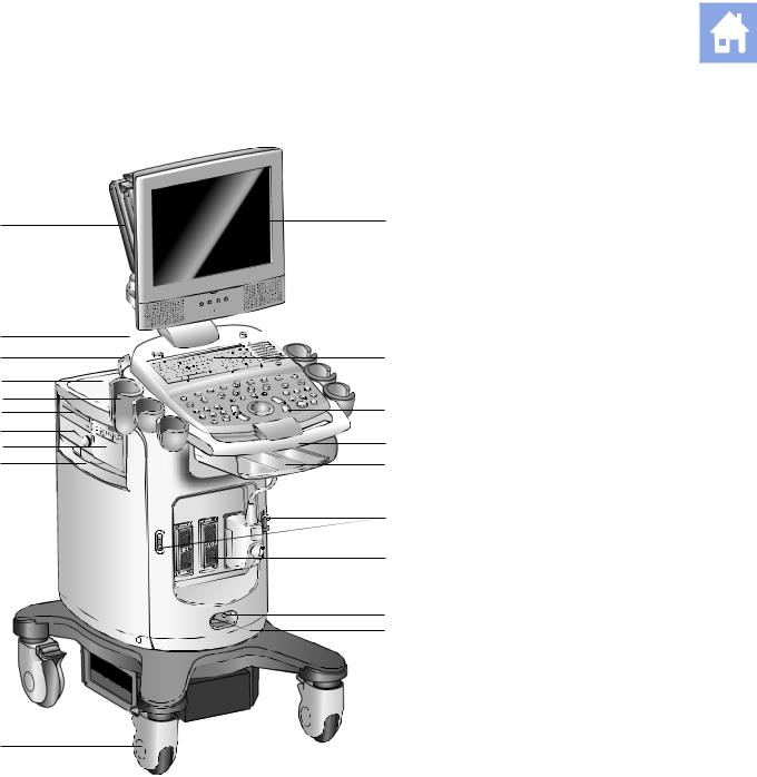
System Review
19
18
17
16
15 
14
13 12
11
10
Example of the ultrasound system, left front view.
1User-adjustable monitor with two forward-facing speakers
2Alphanumeric keyboard
3Back-lit control panel
4Front handle
5Storage shelf
6Transducer cable hanger
7Transducer ports
8CW transducer port
9Footswitch connector
10Swivel wheel with brake
11Air filter
12Black-and-white printer
13Physio module (with ECG and auxiliary connectors)
14CD/DVD-R/W drive
15Transducer and gel holders
16Rear shelf
17Transducer cable hanger
18Power (partial) ON/OFF switch ( )
)
19Articulating arm
|
1 — 4 |
I N S T R U C T I O N S F O R U S E |
![]()
|
2 |
||
|
5 |
||
|
+ |
+ |
|
|
4 |
+ |
+ |
3
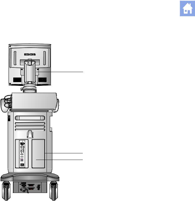
Example of the ultrasound system, back view.
1Monitor
2Cable hanger
3Power panel with circuit breaker
4Swivel wheel with brake
5Input/Output panel
|
I N S T R U C T I O N S F O R U S E |
1 — 5 |

1 Introduction
Intended Use
Caution: In the United States of America, federal law restricts this device to sale or use by, or on the order of, a physician.
The X300 ultrasound system supports the following applications:
Abdomen
Obstetrics
Obstetrics (Japan)1
Early Obstetrics
Gynecology
Musculoskeletal
Small Parts
Breast
Testicle
Thyroid
Urology
Orthopedic
Cerebrovascular
Cardiac
Peripheral vascular
Venous
Renal
Superficial Musculoskeletal
Pediatric Abdomen
Pediatric Echo
Penile
Emergency Medicine
Fetal Echo
Transcranial
Digital
Neonatal Head
TEE (Adult transesophageal)
1 SONOVISTA Systems Only
|
1 — 6 |
I N S T R U C T I O N S F O R U S E |

1 Introduction
Transducers and Intended Applications
Only the following transducers from Siemens are compatible with the
Siemens ACUSON X300 ultrasound imaging system:
|
TRANSDUCER |
OPERATING |
MODES OF |
||
|
NAME |
FREQUENCY |
OPERATION |
INTENDED APPLICATIONS |
|
|
CURVED AND LINEAR ARRAY TRANSDUCERS |
||||
|
CH5-2 |
2.0 |
– 5.0 MHz |
2D, C, D, M |
Obstetrics, Early Obstetrics, Gynecology, Abdomen, |
|
Renal, Urology, Fetal Echo, Emergency Medicine, |
||||
|
Peripheral Vascular, Venous |
||||
|
C8-5 |
5.0 |
– 8.0 MHz |
2D, C, D, M |
Pediatric Abdomen, Neonatal Head, Pediatric Echo, |
|
Cerebrovascular |
||||
|
VF10-5 |
5.0 |
– 10 MHz |
2D, C, D, M |
Cerebrovascular, Peripheral Vascular, Thyroid, |
|
Testicle, Breast, Musculoskeletal, Venous, |
||||
|
Orthopedic, Emergency Medicine |
||||
|
VF13-5 |
5.0 |
– 13 MHz |
2D, C, D, M |
Breast, Thyroid, Testicle, Musculoskeletal, Superficial |
|
Musculoskeletal, Digital, Penile, Cerebrovascular, |
||||
|
Venous |
||||
|
VF13-5SP |
5.0 |
– 13 MHz |
2D, C, D, M |
Cerebrovascular, Musculoskeletal, Venous, Small |
|
Parts |
||||
|
VF8-3 |
3.0 |
– 8.0 MHz |
2D, C, D, M |
Cerebrovascular, Peripheral Vascular, Venous, |
|
Musculoskeletal, Thyroid, Testicle |
||||
|
PHASED ARRAY TRANSDUCERS |
||||
|
P4-2 |
2.0 |
– 4.0 MHz |
2D, C, D, M, SCW |
Cardiac, Abdomen, Renal, Gynecology, Obstetrics, |
|
Transcranial, Emergency Medicine |
||||
|
P8-4 |
4.0 |
– 8.0 MHz |
2D, C, D, M, SCW |
Pediatric Abdomen, Renal, Pediatric Echo, Neonatal |
|
Head |
||||
|
P5-1 |
1.0 |
– 5.0 MHz |
2D, C, D, M, SCW |
Cardiac, Abdomen, Obstetrics, Transcranial, Pediatric |
|
Echo |
||||
|
V5Ms |
3.5 |
– 6.0 MHz |
2D, C, D, M, SCW |
Adult transesophageal |
|
ENDOCAVITY TRANSDUCERS |
||||
|
EC9-4 |
4.0 |
– 9.0 MHz |
2D, C, D, M |
Urology, Obstetrics, Early Obstetrics, Gynecology |
|
ENDOVAGINAL TRANSDUCERS |
||||
|
EV9-4 |
4.0 |
– 9.0 MHz |
2D, C, D, M |
Obstetrics, Early Obstetrics, Gynecology, Emergency |
|
Medicine |
||||
|
CONTINUOUS WAVE TRANSDUCERS |
||||
|
CW2 |
2 MHz |
CW |
Cardiac, Pediatric Echo |
|
|
CW5 |
5 MHz |
CW |
Pediatric Echo, Cerebrovascular |
EMC Note: Operating the transducer in close proximity to sources of strong electromagnetic fields, such as radio transmitter stations or similar installations may lead to temporary degradation or interference visible on the monitor screen. A lightening of image background may be noticed while visualizing hypoechoic structures, or color spectral interference, or jitter, or horizontal lines in the image screen may occur. The transducer and the system have been designed and tested to withstand such interference and will not be permanently damaged. Refer to the Electromagnetic Emissions and Immunity Guidance and Manufacturer’s Declaration.
|
I N S T R U C T I O N S F O R U S E |
1 — 7 |

1 Introduction
Image Screen Layout
The monitor on the ultrasound system displays clinical images together with important operating parameters and patient data. There is a variety of on-screen overlays and graphical objects to aid in image evaluation.
Many fields or areas of data displayed on the screen are multi-functional. The image field can display a 2D-mode image, M-mode sweep, Doppler spectrum, and their combinations, sets of calipers, pictograms and annotation text, and CINE icons. An image can be inverted on a vertical axis and reversed on a horizontal axis to facilitate viewing and measurements.
The system displays reduced-size reference images (thumbnails) of images, clips, and volumes stored during the exam.
EMC Note: Operating the ultrasound imaging system in close proximity to sources of strong electromagnetic fields, such as radio transmitter stations or similar installations, may lead to interference visible on the monitor screen. However, the device has been designed and tested to withstand such interference and will not be permanently damaged.
Screen Saver
The screen saver feature automatically replaces the display with a blank screen after the system has been inactive for a specified number of minutes.
When the screen saver is activated, the system is automatically placed into freeze mode.
Restore the screen display by pressing any key or adjusting any control. The first key that you press will restore the view without performing a function. Press the key again to execute the command.
Use the system presets to enable the screen saver feature and to specify the delay period and the background for the blank screen.
Display > Monitor > Enable Screen Saver
Display > Monitor > Screen Saver Delay
Display > Monitor > Screen Saver Type
|
1 — 8 |
I N S T R U C T I O N S F O R U S E |
1 Introduction
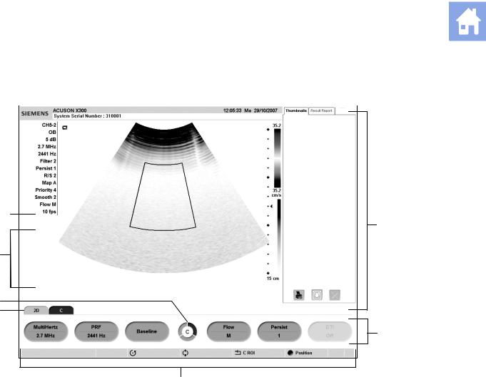
Sample Image Screen
|
1 |
2 |
||||||||||||||
|
13 |
SIEMENS |
10:15:04 03/03/xx |
|||||||||||||
|
12 |
|||||||||||||||
|
11 |
|||||||||||||||
|
10 |
|||||||||||||||
|
9 |
|||||||||||||||
3
8
7
6
4
5
Example of a typical image screen.
1Information for identifying the patient, operator, and the hospital or clinic.
2Time and Date
3Panels including Thumbnails with controls for printing, deleting, and deselecting an image, clip, or volume and Patient Info for displaying patient information.
4Soft key selections for a mode or function, including controls for image optimization, post-processing, measurement types, annotations, and playback. Use the corresponding toggle key on the control panel to activate the selection. Rotate the PAGE control on the control panel to access additional selections for the mode or function. Press the PAGE control to access soft key selections for other modes or functions.
5Page Indicator for the soft key selections. The number of available «pages» for a specific mode or function are identified by the number of sections in the «page indicator». The highlighted section corresponds to the displayed «page» of soft key selections.
6Tab Indicator. Identifies the mode or function for the soft key selections.
7Status bar. Indicates the function currently assigned to the trackball, SELECT control, UPDATE key, ESCAPE key. During video recording, provides recording status and an icon to indicate microphone function is active.
8During the Measurement function, the system displays the Measurement Label menu for the priority imaging mode and exam type. Use the CALIPER key to access the Measurement Menu. During annotation, the system displays the library of pre-defined labels for identifying body position and anatomical structures by exam type.
9Imaging Parameters. Displays settings for parameters adjusted by the soft key selections. Measured Results. Displays values from measurements and calculations when the Measurement function is active.
10Transducer Frequency
11Gain for the priority mode
12Active Exam type
13Active transducer name
|
I N S T R U C T I O N S F O R U S E |
1 — 9 |

1 Introduction
Status Bar
Icon Description
Indicates recording status during video recording using a VCR or DVR. A red icon displays during recording and a white icon displays during pause or stop. The recording time also displays beside the icon.
Indicates the function currently assigned to the SELECT control.
Indicates the function currently assigned to the UPDATE key.
Indicates the function currently assigned to the ESCAPE key. Press the ESCAPE key to cycle through the functions for other active modes under control of the key, if any.
Indicates the function currently assigned to the trackball. Press the SET key to cycle through other functions under control of the trackball, if any.
When displayed, indicates recording function with the built-in microphone is activated.
User-Defined System Settings
You can customize many features of the ultrasound system by using the system presets to designate default settings, or presets. The values are stored in non-volatile memory and will remain intact when the system is powered off.
Each user of the system can determine settings for imaging preferences and default settings, then store them on a disk. Those user-defined settings can then be loaded along with new system software. The disk also serves as a backup.
QuickSets
The QuickSet™ feature allows you to capture an optimized configuration of imaging parameter settings for a combination of a specific transducer and exam.
|
1 — 10 |
I N S T R U C T I O N S F O R U S E |

2 Safety and Care |
|
|
Operating Safety and Environment…………………………………………………………. |
3 |
|
System Symbols……………………………………………………………………………….. |
3 |
|
Labels……………………………………………………………………………………………… |
7 |
|
Biohazard Considerations…………………………………………………………………… |
9 |
|
Note on Fetal Examinations ……………………………………………………….. |
10 |
|
Acoustic Output — Mechanical and Thermal Indices ……………………………. |
10 |
|
Mechanical and Thermal Indices…………………………………………………. |
11 |
|
Transmit Power Control……………………………………………………………… |
12 |
|
Transmit Power Display……………………………………………………………… |
13 |
|
Imaging Functions that Change Acoustic Output …………………………… |
14 |
|
Transducer Surface Temperature Limits …………………………………………….. |
15 |
|
Electrical Safety………………………………………………………………………………. |
15 |
|
Level of Protection Against Electrical Shock — Transducers …………… |
17 |
|
Defibrillators …………………………………………………………………………….. |
17 |
|
Pacemakers …………………………………………………………………………….. |
17 |
|
Possible Combinations with Other Equipment……………………………….. |
17 |
|
Ultrasound System — Care ………………………………………………………………….. |
18 |
|
Daily Checklist ………………………………………………………………………………… |
18 |
|
Maintenance …………………………………………………………………………………… |
19 |
|
Repair……………………………………………………………………………………… |
19 |
|
Siemens Authorized Care…………………………………………………………… |
19 |
|
Cleaning and Disinfecting …………………………………………………………………. |
21 |
|
Cleaning and Disinfecting the System………………………………………….. |
21 |
|
Cleaning an Air Filter…………………………………………………………………. |
23 |
|
Caring for the Battery Pack……………………………………………………………….. |
25 |
|
Battery Pack Location ……………………………………………………………….. |
25 |
|
Battery Pack Replacement and Disposal ……………………………………… |
26 |
|
Battery Pack Disposal ……………………………………………………………….. |
27 |
|
Documentation and Storage Devices — Care………………………………………… |
28 |
|
Transducers — Care…………………………………………………………………………….. |
28 |
|
Cleaning and Disinfecting Transducers ………………………………………………. |
29 |
|
IPX8 Immersion Levels………………………………………………………………. |
31 |
|
Approved List of Pre-Cleaners and Low-Level Disinfectants……………. |
32 |
|
Approved List of Disinfectants …………………………………………………….. |
33 |
|
Sterilizing Transducers — VF13-5SP …………………………………………………. |
34 |
|
Storage………………………………………………………………………………………….. |
34 |
|
Repair……………………………………………………………………………………………. |
34 |
|
Protective case ……………………………………………………………………………….. |
34 |
|
I N S T R U C T I O N S F O R U S E |
2 — 1 |

2 Safety and Care
|
Transducer Accessories — Care…………………………………………………………… |
35 |
|
Transducer Sheaths ………………………………………………………………………… |
35 |
|
Storage……………………………………………………………………………………. |
35 |
|
Gel Pad………………………………………………………………………………………….. |
36 |
|
Storage……………………………………………………………………………………. |
36 |
|
Needle Guide Bracket Kits………………………………………………………………… |
36 |
|
Storage and Transportation………………………………………………………… |
36 |
|
Cleaning, Disinfecting, and Sterilizing — Needle Guide Bracket Kits… |
36 |
|
Universal Needle Guide, Stainless ………………………………………………. |
37 |
|
Storage……………………………………………………………………………………. |
37 |
|
Product Recycling and Disposal…………………………………………………………… |
38 |
|
2 — 2 |
I N S T R U C T I O N S F O R U S E |
2 Safety and Care
Operating Safety and Environment
Do not operate the ultrasound imaging system until you fully understand the safety considerations and procedures presented in this manual.
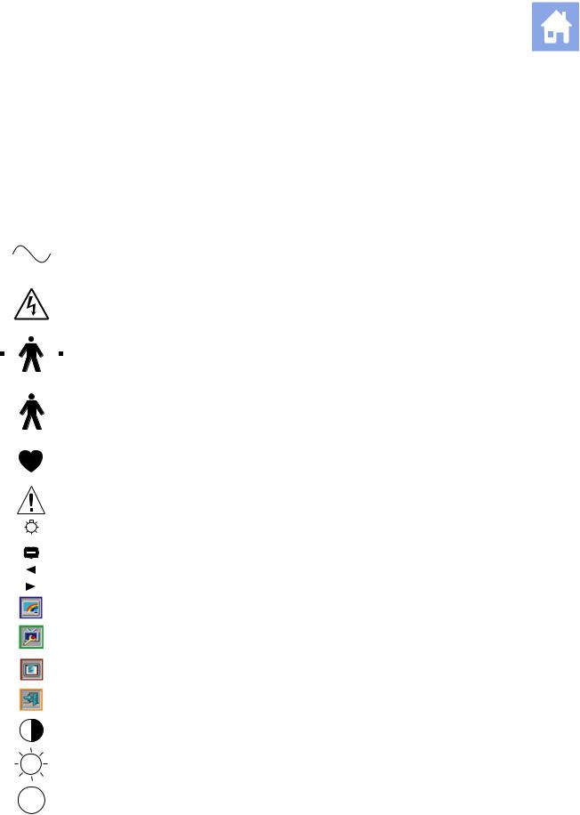
System Symbols
The table below is provided for your identification of important symbols located in labels on the ultrasound imaging system and transducers.
|
Symbol |
Explanation |
|||||||||||||||
|
Alternating Current |
||||||||||||||||
|
V~ |
AC (alternating current) voltage source |
|||||||||||||||
|
Caution: Risk of electric shock |
||||||||||||||||
|
Type BF Defibrillator-proof Patient Connection |
||||||||||||||||
|
Type BF Applied Part |
||||||||||||||||
|
Type CF Patient Connection |
||||||||||||||||
|
Consult Operator’s Manual |
||||||||||||||||
|
Control Panel Task Light |
||||||||||||||||
|
Indicator Light |
||||||||||||||||
|
Monitor Menu Control |
||||||||||||||||
|
Monitor Menu Control, left (decrease) |
||||||||||||||||
|
Monitor Menu Control, right (increase) |
||||||||||||||||
|
Monitor Picture menu icon |
||||||||||||||||
|
Monitor Function menu icon |
||||||||||||||||
|
Monitor OSD menu icon |
||||||||||||||||
|
Monitor menu Exit icon |
||||||||||||||||
|
Monitor Contrast |
||||||||||||||||
|
Monitor Brightness |
||||||||||||||||
|
Protective Earth Ground |
||||||||||||||||
|
Signal Earth Ground |
||||||||||||||||
|
I N S T R U C T I O N S F O R U S E |
2 — 3 |
2 Safety and Care
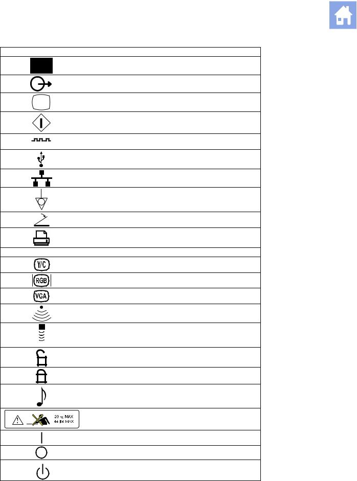
Symbol Explanation
Signal Input
Signal Output
Video Connection (monochrome video signals)
Start (of action for equipment)
Digital Interface, RS-232-C connection
USB Connection
Ethernet 10/100BaseT Connection
Equipotential Connection
Footswitch Connector
Printer Connection
|
B/W |
Black and White Printer Connection |
|
Video Luma/Color |
|
|
Video Red, Green, Blue |
|
|
VGA |
|
|
Electronic Array Transducer Port |
|
|
Continuous Wave Doppler Transducer Port |
|
|
Unlocked position |
|
|
Locked position |
|
|
Audio |
|
|
Shelf Weight Restriction |
|
|
ON only for MAINS control |
|
|
OFF only for MAINS control |
|
|
Power «On» standby switch |
|
2 — 4 |
I N S T R U C T I O N S F O R U S E |
![]()
2 Safety and Care
|
Symbol |
Explanation |
|
ECG Socket |
|
|
IPX8 |
Protected against the effects of continuous immersion in water |
|
Do not open. Refer servicing to qualified service personnel |
|
|
Danger: Risk of explosion if used in the presence of flammable |
|
|
anesthetics |
|
|
Manufacturer’s declaration of product compliance with applicable |
|
|
0123 |
EEC directive(s) and the European Notified Body |
|
Manufacturer’s declaration of product compliance with applicable |
|
|
EEC directive(s) |
|
|
UL symbol for listing as recognized components for Canada and |
|
|
E170920 |
United States of America |
|
Gost-R symbol indicates that this product is certified for conformity |
|
|
to the safety requirements of Russian state standards |
|
|
(Installierte Volumen Komponente) |
|
|
IVK |
Identifier of selected system components or parts for product |
|
traceability |
|
|
UL classified symbol for Canada and United States of America |
|
|
Bar Code |
|
|
Date of Manufacture symbol with the date below |
|
|
2006 |
|
|
Do not install wet |
|
|
Location of air filter |
|
|
60ºC |
Storage temperature range (example) |
-40ºC
Indicates this side up
Do not stack
Shipping weight (example)
Do not allow to get wet
Fragile. Handle with care
|
I N S T R U C T I O N S F O R U S E |
2 — 5 |
2 Safety and Care
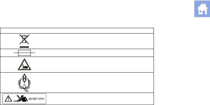
Symbol Explanation
Do not dispose of by dumping in garbage. Use a separate collection for electrical and electronic equipment.
Fuse
Pinch hazard.
Control panel height adjustment
Do not lean against the monitor.
|
2 — 6 |
I N S T R U C T I O N S F O R U S E |
2 Safety and Care
Labels
1
1Monitor label
2System warning and Certification label
3Identification label
|
I N S T R U C T I O N S F O R U S E |
2 — 7 |

2 Safety and Care
Example of monitor label.
Example of system warning label with certification labels.
|
Diagnostic Ultrasound System |
ACUSON X300 |
|
Model |
|
|
Manufacture Date |
|
|
(1P)Model No. |
System |
|
IVK |
|
|
(S)Serial No. |
Product Status Number |
Siemens Medical Solutions USA, Inc. Mountain View
CA 94043 USA
Made in Korea
Example of identification label.
|
2 — 8 |
I N S T R U C T I O N S F O R U S E |

2 Safety and Care
Biohazard Considerations
WARNING: This equipment is not suitable for intracardiac use or direct cardiac contact.
WARNING: For neonatal head imaging, Siemens recommends that you exercise special care during neonatal cephalic scanning to avoid possible damage to the posterior region of the eye. The ultrasound energy emitted by the transducer easily penetrates the fontanels of the infant.
WARNING: Siemens makes every effort to manufacture safe and effective transducers. You must take all necessary precautions to eliminate the possibility of exposing patients, operators, or third parties to hazardous or infectious materials. These precautions should be considered in the use of any application that may indicate the need for such care, and during endocavity or intraoperative scanning; during biopsy or puncture procedures; or when scanning patients with open wounds.
WARNING: To eliminate the possibility of exposing patients, operators, or third parties to hazardous or infectious materials, always dispose hazardous or infectious materials according to medical regulations for biohazardous waste.
WARNING: There have been reports of severe allergic reactions to medical devices containing latex (natural rubber). Health care professionals are advised to identify latex-sensitive patients and to be prepared to treat allergic reactions promptly. For additional information in the U.S.A., refer to FDA Medical Alert MDA91-1.
WARNING: Ultrasound energy is transmitted more effectively through water than through tissue. When using a standoff device of any kind, for example, a gel pad, the actual mechanical and thermal indices, MI and/or TI, may be higher than indicated in the output display on the system.
The assessment of the biological effects of diagnostic ultrasound on humans is a subject of ongoing scientific research. This system, and all diagnostic ultrasound procedures, should be used for valid reasons, for the shortest possible period of time, and at the lowest mechanical and thermal indices necessary to produce clinically acceptable images.
According to the ALARA (As Low As Reasonably Achievable) principles, acoustic output should be set to the lowest level required to satisfactorily perform the examination.
The ultrasound imaging system complies with the standards of the American Institute of Ultrasound in Medicine (AIUM), the National Electrical Manufacturer’s Association (NEMA), the guidelines of the United States Food and Drug Administration (FDA), and the guidelines of the International Electrotechnical Commission (IEC) in terms of safety and acoustic output levels. The ultrasound output levels are stated to permit the user to critically evaluate the system settings in the event of new research findings being announced.
|
I N S T R U C T I O N S F O R U S E |
2 — 9 |

2 Safety and Care
Note on Fetal Examinations
The following recommendation is excerpted from the National Institute of Health in the United States of America. Consensus Statement on the Use of Ultrasound Imaging During Pregnancy, Volume 5, No. 1, based on the recommendation issued at the Health Consensus Development Conference, February, 1984:
Ultrasound examination in pregnancy should be performed for a specific medical indication. The data on clinical efficacy and safety do not allow a recommendation for routine scanning at this time.
Ultrasound examination performed solely to satisfy the family’s desire to know the fetal sex, to view the fetus, or to obtain a picture of the fetus should be discouraged. In addition, visualization of the fetus solely for educational or commercial demonstrations without medical benefit should not be performed.
In August 1994, the Food and Drug Administration (FDA) notified the medical community and the ultrasound industry regarding its concerns about the misuse of diagnostic ultrasound equipment for non-medical purposes, and to discourage patients from having sonograms for non-medical reasons.
The American Institute of Ultrasound in Medicine (AIUM) has also advocated the responsible use of diagnostic ultrasound for all fetal imaging (August 2005).
Acoustic Output — Mechanical and Thermal Indices
WARNING: Ultrasound procedures should be used for valid reasons, for the shortest period of time, and at the lowest mechanical/thermal index setting necessary to produce clinically acceptable images.
The ultrasound system incorporates an output display of Mechanical and Thermal Indices to allow you to monitor, and to limit, the amount of ultrasound energy that is transferred to the patient.
Note: For systems distributed in the United States of America, refer to the Medical Ultrasound Safety ultrasound education program brochure produced by the AIUM that is shipped with the ultrasound system.
See also: Acoustic Output Reference, Appendix D, Instructions for Use
|
2 — 10 |
I N S T R U C T I O N S F O R U S E |
2 Safety and Care
Mechanical and Thermal Indices
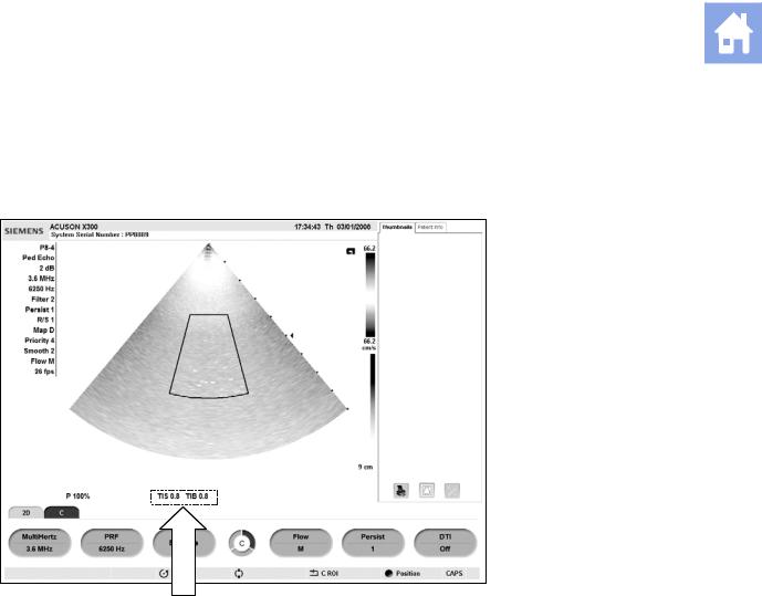
The system displays the Mechanical and Thermal Indices during real-time imaging, in all imaging modes, when the Mechanical Index or the Thermal Indices are equal to or exceed a value of 0.4.
|
SIEMENS ACUSON X300 |
17:34:43 Th 03/01/xxxx |
Location of mechanical and thermal indices on the image screen.
Indices display in the abbreviated form shown below:
MI: Mechanical Index
TIB: Bone Thermal Index (fetal application)
TIS: Soft Tissue Thermal Index
TIC: Cranial Thermal Index
|
I N S T R U C T I O N S F O R U S E |
2 — 11 |

2 Safety and Care
Transmit Power Control
Adjust the transmit power and the corresponding acoustic pressure delivered through the transducer to the patient by using the designated control on the system. It is the main system function that determines the transmitted intensity of ultrasound for all transducers and imaging modes during real-time imaging, though it is not the only function that affects the mechanical and thermal indices. The range and especially the maximum level of the mechanical and thermal indices differ depending on the transducers. In addition, each diagnostic exam type has preset values for mechanical and thermal indices.
See also: Imaging Functions that Change Acoustic Output, p. 2-14
Note: Maximum transmit acoustic intensity and the mechanical index for each exam type are limited in accordance with the United States Food and Drug Administration’s (FDA) recommendations and guidelines. System default transmit intensity and mechanical index values are always below the FDA recommendations for each exam type. Although some exam types may default to a condition of maximum allowable transmit power, there are other system controls or functions that could raise acoustic output levels.
To increase the transmit power:
During real-time imaging, press the toggle key for P upward to increase transmit power.
To decrease the transmit power:
During real-time imaging, press the toggle key for P downward to decrease transmit power.
|
2 — 12 |
I N S T R U C T I O N S F O R U S E |
2 Safety and Care
Transmit Power Display
The transmit power range is from 0% to 100%. Selecting 100%, in combination with other system controls or functions, generates the maximum acoustic intensity and mechanical index for each transducer, where:
ISPTA.3 : ≤ 720 mW/cm2 and MI ≤ 1.9
|
Percentage (%) |
Decibels (dB) |
Percentage (%) |
Decibels (dB) |
|
100% |
0 dB |
4.0% |
-28 dB |
|
79% |
-2 dB |
3.2% |
-30 dB |
|
63% |
-4 dB |
2.5% |
-32 dB |
|
50% |
-6 dB |
2.0% |
-34 dB |
|
40% |
-8 dB |
1.6% |
-36 dB |
|
32% |
-10 dB |
1.3% |
-38 dB |
|
25% |
-12 dB |
1.0% |
-40 dB |
|
20% |
-14 dB |
0.79% |
-42 dB |
|
16% |
-16 dB |
0.63% |
-44 dB |
|
13% |
-18 dB |
0.40% |
-46 dB |
|
10% |
-20 dB |
0.50% |
-48 dB |
|
7.9% |
-22 dB |
0.32% |
-50 dB |
|
6.3% |
-24 dB |
0.25% |
-52 dB |
|
5.0% |
-26 dB |
0.20% |
-54 dB |
Comparison of decibels to percentages.
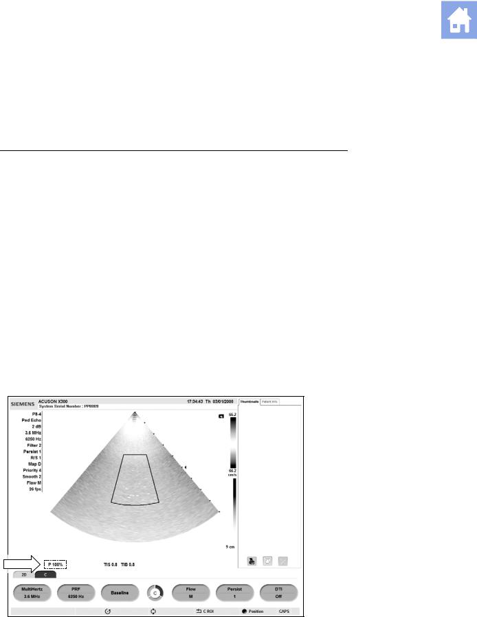
When the power level is changed, the system briefly highlights the power value to indicate the change.
|
SIEMENS ACUSON X300 |
17:34:43 Th 03/01/xxxx |
Location of power display on the image screen.
|
I N S T R U C T I O N S F O R U S E |
2 — 13 |

2 Safety and Care
Imaging Functions that Change Acoustic Output
WARNING: Observe the real-time display of mechanical and thermal indices (MI/TI) at all times.
In addition to the adjustment of the transmit power, adjustment of the following imaging functions and/or controls may affect the acoustic output:
Automatic Time-out
M-mode cursor
Color and Power ROI Position and Size; Steering Angle for linear array transducers
Doppler Gate Position and Size; Steering Angle for linear array transducers
Doppler PRF
Color PRF
Exam Type
Field of View (Scan Angle); 2D Steering Angle for linear array transducers
Focus
Zoom
Frame Rate
Freeze
Image Depth
Imaging Mode
Multi-Frequency
Power On/Off
System Presets and QuickSets
THI
Resolution/Speed
Simultaneous/Update
Transducer
Gel pad use
|
2 — 14 |
I N S T R U C T I O N S F O R U S E |
![]()
2 Safety and Care
Transducer Surface Temperature Limits
The following table provides the maximum surface temperature of the transducers compatible with the system.
Maximum surface temperatures are in accordance with IEC 60601-2-37.
Note: The systemic uncertainty of the transducer surface temperature is estimated as 1.39° C.
|
Maximum Temperature |
||
|
Transducer |
TMM |
Still Air |
|
CH5-2 |
<41.4° C |
<42.5° C |
|
C8-5 |
<33.1° C |
<43.5° C |
|
VF8-3 |
<33.5° C |
<46.2° C |
|
VF10-5 |
<41.1° C |
<42.7° C |
|
VF13-5 |
<41.4° C |
<42.7° C |
|
VF13-5SP |
<41.2° C |
<42.5° C |
|
EV9-4 |
<42.3° C |
<43.6° C |
|
EC9-4 |
<41.7° C |
<43.8° C |
|
P4-2 |
<42.2° C |
<44.1° C |
|
P5-1 |
<41.5° C |
<46.0° C |
|
P8-4 |
<41.2° C |
<42.1° C |
|
V5Ms |
<41.6° C |
<44.3° C |
|
CW2 |
<31.5° C |
<35.5° C |
|
CW5 |
<27.0° C |
<32.0° C |
TMM = Tissue Mimicking Material
Electrical Safety
WARNING: For systems used in the U.S.A.: To ensure grounding reliability, only connect the system to a hospital-grade power outlet.
WARNING: The AC power connector plug for the ultrasound system is a three-prong grounded plug (in the U.S.A.) and should never be adapted to any two-prong (non-grounded) outlet, either by modifying the plug or by using an adapter. In the U.S.A., proper grounding requires the
AC power connector plug to be plugged into a hospital-grade power outlet.
WARNING: To avoid electrical shock, never modify the ultrasound system’s AC power connector plug, as doing so may overload your facility’s power circuits. To ensure grounding reliability, connect the system only to an equivalent outlet.
WARNING: To avoid electrical shock, never use equipment or a MAINS power cord that shows signs of wear or tampering, or whose ground plug has been bypassed using an adapter.
WARNING: Equipment connected to the ultrasound system and in the patient zone must be powered from a medically-isolated power source or must be a medically-isolated device. Equipment powered from a non-isolated source can result in chassis leakage currents exceeding safe levels. Chassis leakage current created by an accessory or device connected to a non-isolated outlet may add to the chassis leakage current of the ultrasound system.
|
I N S T R U C T I O N S F O R U S E |
2 — 15 |

2 Safety and Care
WARNING: Using an extension cord or multi-socket outlet setup to provide power to the imaging system, or to the system’s peripheral devices may compromise the system grounding and cause your system to exceed leakage current limits.
WARNING: To avoid electrical shock and damage to the ultrasound system, power off and unplug the equipment from the AC power outlet before cleaning and disinfecting.
WARNING: Do not pour any fluid onto the ultrasound system surfaces, as fluid seepage into the electrical circuitry may cause excessive leakage current or system failure.
WARNING: To ensure proper grounding and leakage current levels, it is the policy of Siemens to have an authorized Siemens representative or Siemens-approved third party perform all on-board connections of documentation and storage devices to the ultrasound system.
WARNING: To maintain the safety and functionality of the ultrasound system, maintenance must be performed every 12 months. Electrical safety tests must also be performed at regular intervals as specified by local safety regulations, or as needed.
Caution: To avoid the possibility of static shock and damage to the system, avoid the use of aerosol spray cleaners on the monitor screens.
Caution: Do not use spray cleaners on the ultrasound system, as this may force cleaning fluid into the system and damage electronic components. It is also possible for the solvent fumes to build up and form flammable gases or damage internal components.
Caution: To reduce the risk of fire and subsequent equipment damage, use only 26 gauge (0.14 mm2) or heavier wire for the cable connecting to the Ethernet port located on the ultrasound system.
EMC Note: Operating the ultrasound system in close proximity to sources of strong electromagnetic fields, such as radio transmitter stations or similar installations, may lead to interference visible on the monitor screen. However, the device has been designed and tested to withstand such interference and will not be permanently damaged.
|
2 — 16 |
I N S T R U C T I O N S F O R U S E |
2 Safety and Care
Level of Protection Against Electrical Shock — Transducers
WARNING: Only use Type BF transducers with the ultrasound system to maintain a level of protection against electrical shock.
According to EN 60601-1 and IEC 60601-1, the assemblies for the linear, curved, and phased array transducers provide a «Level of Protection Against Electrical Shock» of «Type BF.»
The Type BF icon is located on the transducer label.
Defibrillators
WARNING: The ECG function is designed to withstand the effects of defibrillation. However, when possible, disconnect the ECG leads during defibrillation since a malfunction of the safety controls could otherwise result in electrical burns for the patient.
For patient safety, be sure to use defibrillators that do not have grounded patient circuits.
Pacemakers
WARNING: Pacemakers may be susceptible to the high frequency electrical signal generated by ultrasound equipment. Use precautions when using ultrasound equipment on or near someone with a pacemaker. If there is interference, immediately discontinue the examination and power off the ultrasound system.
Possible Combinations with Other Equipment
WARNING: Accessory equipment connected to the analog and digital interfaces must be certified according to the respective EN and IEC standards (for example, EN 60950 and IEC 60950 for data processing equipment and EN 60601-1 and IEC 60601-1 for medical equipment). Furthermore, all configurations shall comply with the system standards
EN 60601-1-1 and IEC 60601-1-1. Anyone who connects additional equipment to any of the signal input or signal output ports configures a medical system and is therefore responsible that the system complies with the requirements of the system standards EN 60601-1-1 and
IEC 60601-1-1. Siemens can only guarantee the performance and safety of the devices listed in the Instructions for Use. If in doubt, consult the Siemens service department or your local Siemens representative.
The ultrasound system supports three on-board documentation devices. The ultrasound system can support two on-board documentation devices at one time.
On-board peripheral devices must be installed by an authorized Siemens representative or by a Siemens-approved third party. Devices installed by other people will be at the user’s risk and may void the system warranty.
|
I N S T R U C T I O N S F O R U S E |
2 — 17 |

2 Safety and Care
Ultrasound System — Care
It is the responsibility of the user to verify that the ultrasound system is safe for diagnostic operation on a daily basis. Each day, prior to using the system, perform each of the steps in the Daily Checklist.
All exterior parts of the system, including the control panel, keyboard, and transducers, should be cleaned and/or disinfected as necessary or between uses. Clean each component to remove any surface particles. Disinfect components to kill vegetative organisms and viruses.
The air filter on the ultrasound system must be cleaned regularly to maintain proper system cooling. Remove and check the air filter weekly, and clean as needed.
Daily Checklist
Perform the following each day before using the ultrasound system:
Visually inspect all transducers. Do not use a transducer which has a cracked, punctured, or discolored casing or a frayed cable.
WARNING: To avoid electrical shock, you must visually inspect a transducer prior to use. Do not use a transducer that has a cracked, punctured, or discolored casing or a frayed cable.
Discoloration Exception: The use of the approved disinfectants, Cidex OPA and Gigasept FF, may cause discoloration of transducer housings, including the face of the transducer. You can continue to use a transducer if it is discolored due to the use of these specific disinfectants only.
See also: Approved List of Disinfectants, p. 2-33.
Visually inspect all power cords. Do not turn on the power if a cord is frayed or split, or shows signs of wear.
If your system’s power cord is frayed or split, or shows signs of wear, contact your Siemens service representative for power cord replacement.
Visually inspect the ECG connector and the cable. Do not use the ECG function if the connector or cable is damaged or broken.
Verify that the trackball, DGC slide controls, and other controls on the control panel are clean and free from gel or other contaminants.
Once the system is powered on:
Visually check the on-screen displays and lighting.
Verify that the monitor displays the current date and time.
Verify that the transducer identification and indicated frequency are correct for the active transducer.
|
2 — 18 |
I N S T R U C T I O N S F O R U S E |

2 Safety and Care
Maintenance
WARNING: To maintain the safety and functionality of the ultrasound system, maintenance must be performed every 12 months. Electrical safety tests must also be performed at regular intervals as specified by local safety regulations, or as needed.
Repair
For questions regarding repair or replacement of any equipment parts on your system, contact your Siemens service representative.
Siemens Authorized Care
Installers and operators must observe any statutory regulations that govern the installation, operation, inspection, and maintenance of this equipment.
To ensure the safety of patients, operators, and third parties, the equipment must be inspected every 12 months, and the replacement of parts is performed as necessary. This maintenance must be performed by a qualified Siemens authorized representative. It is important to inspect the equipment more frequently if it is operated under extraordinary conditions.
Perform inspections and maintenance at the prescribed intervals to avoid worn and hazardous parts due to wear. Contact the Siemens service department for information regarding the required maintenance. As manufacturers and installers of ultrasound equipment, Siemens cannot assume responsibility for the safety properties, reliability, and/or performance of the equipment, if:
Installations, extensions, readjustments, modifications, additions, or repairs are carried out by persons not specifically authorized by Siemens.
Components that affect the safe operation of the system are replaced by parts not authorized by Siemens.
The electrical installation of the room where the equipment is located does not meet the power and environmental requirements stated in this manual.
The equipment is not used in accordance with the operating instructions.
The system is operated by personnel not adequately educated or trained.
|
I N S T R U C T I O N S F O R U S E |
2 — 19 |

2 Safety and Care
Siemens suggests that you request any person who performs maintenance, or repairs, to provide you with a certificate showing:
The nature and extent of the work performed
Changes in rated performance
Changes in working ranges
Date of service
Name of person or firm performing the service
Signature of person performing the service
Technical documentation pertinent to the ultrasound system is available at an additional charge. However, this does not in any way constitute an authorization to conduct repairs or maintenance. Siemens refuses all responsibility whatsoever for repairs that are performed without the express written consent of the Siemens service department.
WARNING: Accessory equipment connected to the analog and digital interfaces must be certified according to the respective EN and IEC standards (for example, EN 60950 and IEC 60950 for data processing equipment and EN 60601-1 and IEC 60601-1 for medical equipment). Furthermore, all configurations shall comply with the system standards
EN 60601-1-1 and IEC 60601-1-1. Anyone who connects additional equipment to any signal input or signal output ports configures a medical system and is therefore responsible that the system complies with the requirements of the system standards EN 60601-1-1 and
IEC 60601-1-1. Siemens can only guarantee the performance and safety of the devices listed in the Instructions for Use. If in doubt, consult the Siemens service department or your local Siemens representative.
|
2 — 20 |
I N S T R U C T I O N S F O R U S E |

2 Safety and Care
Cleaning and Disinfecting
You must take all necessary precautions to eliminate the possibility of exposing patients, operators, or third parties to hazardous or infectious materials. Use universal precautions when cleaning and disinfecting. You should treat all portions of the imaging system that come in contact with human blood or other body fluids as if they were known to be infectious.
All exterior parts of the system, including the control panel, and transducers, should be cleaned and/or disinfected as necessary or between uses. Clean each component to remove any surface particles. Disinfect the components to kill vegetative organisms and viruses.
Cleaning and Disinfecting the System
WARNING: To avoid electric shock and damage to the system, always power off and disconnect the equipment from the AC power source before cleaning and disinfecting.
WARNING: Contents of some disinfecting agents are known to be health hazards. Their concentration in the air must not exceed an applicable specified limit. Comply with the manufacturer’s instructions when using these agents.
Caution: To avoid the possibility of static shock and damage to the ultrasound system, avoid the use of aerosol spray cleaners on the monitor screens.
Caution: Do not clean the system with chlorinated or aromatic solvents, acidic or basic solutions, isopropyl alcohol or strong cleaners such as ammoniated products, as these can damage the surface of the system. Isopropyl alcohol exception: It is acceptable to use isopropyl alcohol only when recommended for cleaning the trackball assembly. Use the recommended cleaning procedure.
See also: Trackball Cleaning, p. 2-22
Caution: Do not use spray cleaners on the ultrasound system, or pour fluid onto the system surfaces, as fluid can seep into the system and damage electronic components. It is also possible for the solvent fumes to build up and form flammable gases or damage internal components.
Caution: Do not pour any fluid onto the ultrasound system surfaces, as fluid seepage into the electrical circuitry may cause excessive leakage current or system failure.
|
I N S T R U C T I O N S F O R U S E |
2 — 21 |

2 Safety and Care
System Surfaces
The following instructions describe cleaning the surface of the ultrasound system, including the trackball and transducer holder.
To clean the surface of the ultrasound system:
1.Power off ( ) the ultrasound system and unplug the power cord from the power outlet.
2.Use a clean gauze pad or lint-free cloth, lightly moistened with a mild detergent, to wipe the surface of the ultrasound system.
Take particular care to clean the areas near the trackball and the slide controls. Ensure these areas are free of gel and any other visible residue.
Ensure that cleaning solution does not seep into the control panel, keyboard, or any other openings.
3.After cleaning, use a clean, lint-free cloth to dry the surface.
4.After cleaning, reconnect the ultrasound system power cord into the power outlet.
To clean the liners of the transducer holders:
1.Use the tab to remove the liner from the transducer holder.
2.Clean the liner under running water, using a mild detergent and dry with a lint-free cloth.
3.Reinsert the liner into the transducer holder.
See also: System Setup, Chapter 3, Instructions for Use
To clean the trackball:
Caution: Do not drop or place foreign objects inside the trackball assembly. This may affect the trackball’s operation and damage the system.
Caution: Do not submerge the front bezel and Teflon seal in isopopyl alcohol — this may damage the adhesive bond between the two components.
1.Remove the trackball front panel bezel by rotating the bezel counterclockwise.
2.Remove the ball.
3.Clean the ball with tissue and isopropyl alcohol.
4.Clean the Teflon seal (located in the front panel bezel) with a tissue and isopropyl alcohol.
5.Clean the inside of the trackball assembly with a cotton swab and isopropyl alcohol.
6.Allow the assembly parts to completely dry before reassembly.
7.Replace the ball and front panel bezel.
|
2 — 22 |
I N S T R U C T I O N S F O R U S E |
2 Safety and Care
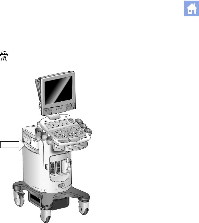
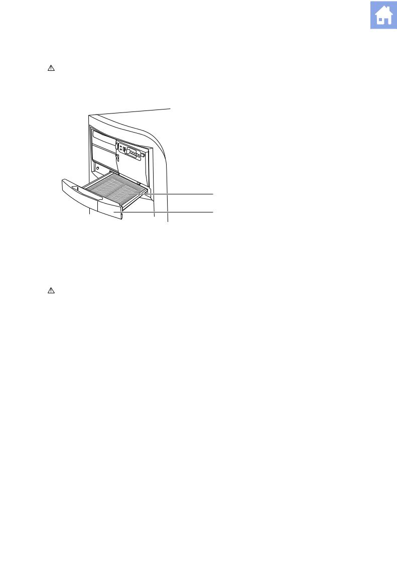
Cleaning an Air Filter
The air filter on the ultrasound system must be cleaned regularly to maintain proper system cooling. Remove and check the air filter weekly, and clean as needed.
The filter location is marked with the air filter symbol.
Location of air filter.
|
I N S T R U C T I O N S F O R U S E |
2 — 23 |
2 Safety and Care
To remove and clean the air filter:
Caution: Do not scrub, stretch, or bend the filter, or apply heat to the filter, as doing so could damage the filter.
1.Power off and unplug the power cord from the power outlet.
2.Grasp the air filter tray and pull it out of the system.
1 Air filter
2 Air filter tray
1
2
Removing the air filter tray.
3.Remove the filter.
4.Rinse the air filter with running water and allow the filter to completely dry.
To hasten drying, you may gently shake the filter, or blot the filter with a clean, lint-free cloth.
Caution: Do not insert a wet filter as this can damage the system.
5.Reinsert the filter into the filter tray.
6.Slide the air filter tray back into the ultrasound system.
7.Plug the power cord into the power outlet.
|
2 — 24 |
I N S T R U C T I O N S F O R U S E |
![]()
2 Safety and Care
Caring for the Battery Pack
WARNING: Do not strike or drop the battery pack because this can cause heat generation, bursting, or fire. Compromising the structural integrity of the battery pack can result in leakage or explosion and the potential for personal injury.
WARNING: Do not use the battery pack if it leaks fluid or has changed shape. If skin or clothing comes in contact with fluid from the battery pack, thoroughly wash the area immediately with clean water. If any fluid comes in contact with a user’s eyes, immediately flush their eyes with water and seek medical attention.
WARNING: Do not allow the battery pack to contact water. Compromising the structural integrity of the battery pack can result in leakage or explosion and the potential for personal injury.
WARNING: Do not disassemble the battery pack. Compromising the structural integrity of the battery pack can result in leakage or explosion and the potential for personal injury.
The battery pack is designed to maintain system memory for a maximum of forty minutes.
The length of the charge time is three hours.
Battery Pack Location
The battery pack is located on the front side of the ultrasound system, where the power is located. The battery pack cover must be removed to access the battery pack.
1 Battery pack location
1
Battery pack location.
|
I N S T R U C T I O N S F O R U S E |
2 — 25 |
2 Safety and Care
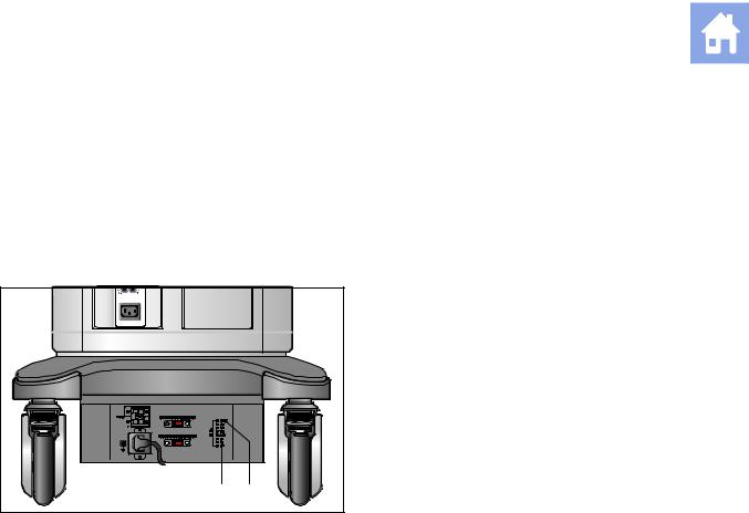
Battery Pack Replacement and Disposal
Replace the battery pack when it is no longer able to hold a charge.
When the system is used with the Mobile QuickStart option and frequently disconnected from the AC power (for a duration of greater than 20 minutes), replace the battery every 6 months.
When the system is used with the Mobile QuikStart option and only occasionally disconnected from the AC power (for a duration of approximately 20 minutes), replace the battery every year.
|
1 |
AC OK indicator LED |
||
|
2 |
Battery pack charge indicator LED |
||
|
+ |
+ |
||
|
+ |
+ |
||
|
2 |
1 |
Example of an AC Tray panel with the battery pack charge indicator LED.
The battery pack charge indicator LED is located at the rear of the system, on the AC Tray panel. A green blinking LED indicates that the battery is actively charging. A solid green LED indicates that the battery pack is fully charged. If the LED is not illuminated, then there is a problem with the battery pack, or the battery pack may be missing.
|
2 — 26 |
I N S T R U C T I O N S F O R U S E |

2 Safety and Care
Battery Pack Disposal
Caution: Never dispose of a battery pack by burning or by flushing into any waste water system, for example, a lavatory. Compromising the structural integrity of the battery pack can result in leakage or explosion and the potential for personal injury.
Caution: Collect and dispose of used battery packs separate from other waste. Do not throw into trash.
The battery pack should be recycled according to local, state and federal regulations. Use a battery collection program available in your country to dispose of the battery pack. The following agencies may be contacted for further collection information:
Australia – Australian Battery Recycling Program (AMTA)
Austria – UFB
Belgium – Bebat
Canada – Rechargeable Battery Recycling Corporation (RBRC)
Denmark – BatteriForeningens
European Union – European Portable Battery Association
France – Societe de Collecte et de Recyclage des Accumulateurs (SCRA)
Finland – (NBA)
Germany – Stiftung Gemeinsames Rucknahmesystem Batterien (GRS)
Italy – COBAT
Japan – Battery Association of Japan
Netherlands – Stibat
Norway – REBATT AS
Portugal – AGEFE
Sweden – CT
Switzerland – Batterieentsorgungs-Selbsthilfeorganisation (BESO)
United Kingdom – REBAT
United States of America – Rechargeable Battery Recycling Corporation (RBRC)
Note: If a local battery recycling program does not exist then return used batteries to the address below. When returning batteries, label the package: «Attn.: Battery Recycling».
Siemens AG
Medical Engineering
TD ML RE
Betr.: Battery Recycling
Am Pestalozziring 3
D-91058 Erlangen
GERMANY
|
I N S T R U C T I O N S F O R U S E |
2 — 27 |

2 Safety and Care
Documentation and Storage Devices — Care
For information on the care of an optional documentation or storage device, please refer to the manufacturer’s operating instructions that accompanied the device.
Transducers — Care
WARNING: Always place a sterile, non-pyrogenic transducer sheath on a transducer used in procedures requiring sterility.
WARNING: To minimize the risk of cross-contamination and infectious diseases, intraoperative transducers must be cleaned and high-level disinfected after each use. A sterile, non-pyrogenic transducer sheath must be in place during procedures requiring sterility.
WARNING: There have been reports of severe allergic reactions to medical devices containing latex (natural rubber). Health care professionals are advised to identify latex-sensitive patients and to be prepared to treat allergic reactions promptly. For additional information in the U.S.A., refer to FDA Medical Alert MDA91-1.
WARNING: During neurosurgical procedures, if a transducer becomes contaminated with tissue or fluids of a patient known to have Creutzfeld-Jacob disease, the transducer should be destroyed, as it cannot be sterilized.
WARNING: When using an endocavity or intraoperative transducer with a CF type applied part, the patient leakage currents may be additive.
WARNING: The outer surfaces of an endocavity or intraoperative transducer should be checked to ensure there are no unintended rough surfaces, sharp edges, or protrusions that may cause a safety hazard.
Caution: Transducers are sensitive instruments – irreparable damage may occur if they are dropped, knocked against other objects, cut, or punctured. Do not attempt to repair or alter any part of a transducer.
Caution: To avoid cable damage, do not roll the system over transducer cables.
Caution: To avoid damage to the transducer, do not use transducer sheaths containing an oil-based coating or petroleumor mineral oil-based ultrasound coupling agents. Use only a water-based ultrasound coupling agent.
Caution: Follow all instructions provided by manufacturers of sterile goods (transducer sheaths) to ensure proper handling, storage, and cycling of all sterile goods.
Take extreme care when handling or storing transducers. They must not be dropped, jarred, or knocked against other objects. Do not allow transducers to come into contact with any sharp-edged or pointed object.
|
2 — 28 |
I N S T R U C T I O N S F O R U S E |

2 Safety and Care
Cleaning and Disinfecting Transducers
WARNING: To avoid electrical shock and damage to the system, disconnect the transducer prior to cleaning or disinfecting.
WARNING: Disinfectants and cleaning methods listed are recommended by Siemens for compatibility with product materials, not for biological effectiveness. Refer to disinfectant label instructions for guidance on disinfection efficacy and appropriate clinical uses.
Caution: Do not sterilize transducers using hot steam, cold gas, or Ethylene Oxide (ETO) methods. Before applying any other methods which might be recommended by manufacturers of sterilization equipment, please contact your Siemens representative.
Caution: To avoid damage to the transducer, observe the immersion levels indicated for each transducer type. Do not immerse or allow the cable or connector of a transducer to become wet.
Caution: The transducers have been designed and tested to be able to withstand high-level disinfection as recommended by the manufacturer of the disinfectant product. Carefully follow the disinfectant manufacturer’s instructions. Do not immerse for more than one hour.
Caution: Do not use abrasive cleaning agents, organic solvents such as benzene, isopropyl alcohol, or phenol-based substances, or cleaning agents containing organic solvents to clean or disinfect transducers. These substances can damage the transducers.
Caution: Do not use a spray cleaner on a transducer, as this may force cleaning fluid inside the housing and damage the transducer.
All transducers should be cleaned and disinfected prior to their use on each patient. Endocavity and intraoperative transducers require high-level disinfection prior to use.
See also: Transesophageal Transducer, Chapter 6, Instructions for Use
|
I N S T R U C T I O N S F O R U S E |
2 — 29 |

2 Safety and Care
To clean a transducer:
1.Disconnect the transducer from the system.
2.Moisten a clean gauze pad with water and wipe the transducer to remove any gel or particles remaining on the transducer. If water is not effective, then you can use an approved pre-cleaner or low-level disinfectant.
3.Carefully wipe the entire transducer, including the cable and connector.
4.After cleaning or disinfecting, use a clean cloth to dry the transducer.
To disinfect or high-level disinfect a transducer:
1.Disconnect the transducer from the system.
2.Thoroughly clean, rinse, and dry the transducer.
3.Take care to keep the cable strain relief and connector of the transducer dry while immersing the transducer in an approved disinfectant to the level indicated in the following illustration.
4.Carefully follow the disinfectant manufacturer’s instructions for disinfection or high-level disinfection.
5.After disinfecting or high-level disinfecting, use a clean cloth to dry the transducer.
|
2 — 30 |
I N S T R U C T I O N S F O R U S E |
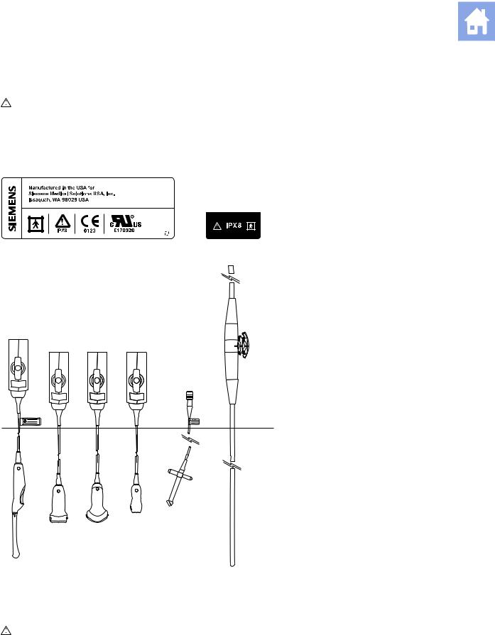
2 Safety and Care
IPX8 Immersion Levels
Caution: To avoid damage to the transducer, observe the immersion levels indicated for each transducer type. Transducers with the protection level IPX8 are indicated by the presence of the «IPX8» symbol on the connector of the transducer.
Transducers meet Ingress Protection level IPX8 of EN 60539 and IEC 60539 to the depth of the immersion line shown in the illustration only for transducers with the «IPX8» symbol on the connector of the transducer.
Example of transducer labels with IPX8 symbol.
!
|
Endocavity Linear Curved Phased Continuous |
V5Ms |
|
Wave (CW) |
|
|
IPX8 Immersion Levels. |
Caution: Do not immerse the label located on the cable of the CW transducer.
Note: Intraoperative transducers are immersible up to the strain relief on the connector.
|
I N S T R U C T I O N S F O R U S E |
2 — 31 |

2 Safety and Care
Approved List of Pre-Cleaners and Low-Level Disinfectants
The following matrix provides a list of approved pre-cleaners and low-level disinfectants for all transducers.
|
Enzol |
Transeptic |
Hi-Tor Plus |
Theracide Plus |
T-Spray II |
Super SaniCloth |
|
|
CH5-2 |
9 |
9 |
9 |
9 |
9 |
9 |
|
C8-5 |
9 |
9 |
9 |
9 |
9 |
9 |
|
VF8-3 |
9 |
9 |
NC |
9 |
9 |
NC |
|
VF10-5 |
9 |
9 |
9 |
9 |
9 |
9 |
|
VF13-5 |
9 |
9 |
9 |
9 |
9 |
9 |
|
VF13-5SP |
9 |
9 |
9 |
9 |
9 |
9 |
|
EV9-4 |
9 |
9 |
9 |
9 |
9 |
9 |
|
EC9-4 |
9 |
9 |
9 |
9 |
9 |
9 |
|
P4-2 |
9 |
9 |
9 |
9 |
9 |
9 |
|
P5-1* |
NC |
NC |
NC |
NC |
NC |
NC |
|
P8-4 |
9 |
9 |
9 |
9 |
9 |
9 |
|
V5Ms |
9 |
9 |
NA |
NA |
9 |
NA |
|
CW2 |
9 |
9 |
9 |
9 |
9 |
9 |
|
CW5 |
9 |
9 |
9 |
9 |
9 |
9 |
9 = compatible
NC = not compatible
NA = not applicable (not tested)
* = Compatible pre-cleaners and low-level disinfectants for the P5-1 transducer include: T-Spray, ANIOS, Wavicide-01, MetriZyme, and Klenzyme.
|
2 — 32 |
I N S T R U C T I O N S F O R U S E |

2 Safety and Care
Approved List of Disinfectants
The following matrix provides a list of approved disinfectants for all transducers.
Note: The approved disinfectants, Cidex OPA and Gigasept FF, may discolor transducer housings, including the face of the transducer. There is no associated degradation of imaging performance or transducer reliability.
|
Cidex |
Cidex Plus |
Cidex OPA |
Milton |
Virkon |
Gigasept FF |
|
|
CH5-2 |
9 |
9 |
9 |
9 |
NC |
9 |
|
C8-5 |
9 |
9 |
9 |
9 |
9 |
9 |
|
VF8-3 |
9 |
9 |
9 |
9 |
9 |
9 |
|
VF10-5 |
9 |
9 |
9 |
9 |
9 |
9 |
|
VF13-5 |
9 |
9 |
9 |
9 |
9 |
9 |
|
VF13-5SP |
9 |
9 |
9 |
9 |
9 |
9 |
|
EV9-4 |
9 |
9 |
9 |
9 |
9 |
9 |
|
EC9-4 |
9 |
9 |
9 |
9 |
9 |
9 |
|
P4-2 |
9 |
9 |
9 |
9 |
NC |
9 |
|
P5-1 |
NC |
9 |
9 |
NC |
9 |
9 |
|
P8-4 |
9 |
9 |
9 |
9 |
NC |
9 |
|
V5Ms |
NC |
9 |
9 |
9 |
NC |
9 |
|
CW2 |
9 |
9 |
9 |
9 |
9 |
9 |
|
CW5 |
9 |
9 |
9 |
9 |
9 |
9 |
9 = compatible
NC = not compatible
NA = not applicable (not tested)
|
I N S T R U C T I O N S F O R U S E |
2 — 33 |

2 Safety and Care
Sterilizing Transducers — VF13-5SP
Caution: The transducers have been designed and tested to be able to withstand sterilization as recommended by the manufacturer of the sterilization system. Carefully follow the sterilization manufacturer’s instructions.
The STERRAD® sterilization system, a hydrogen peroxide gas plasma sterilization system, is approved for use with the listed intraoperative transducer(s).
VF13-5SP
To sterilize a transducer with the STERRAD system:
Note: This procedure applies to the VF13-5SP transducer only.
1.Disconnect the transducer from the system.
2.Thoroughly clean, rinse, and dry the transducer.
3.Carefully follow the manufacturer’s instructions for sterilization.
Storage
Store transducers in a clean and dry environment. Extreme temperatures or humidity may damage a transducer.
See also: Technical Description, Appendix A, Instructions for Use
Repair
Do not attempt to repair or alter any part of the transducer. Contact your service representative at Siemens immediately if a transducer appears to be damaged or malfunctions in any way.
Protective case
Due to the mechanical sensitivity of transducers, Siemens recommends that you always use the transducer case when you ship a transducer or transport it from one place of examination to another. The case is specially designed to protect the sensitive parts of the transducer. Be sure that all parts of the transducer are properly placed inside the case before you close the lid.
|
2 — 34 |
I N S T R U C T I O N S F O R U S E |
-
Pressalit Care R9806
ENMounting instructionNLMontage-voorschriftDKMonteringsvejledningSVMonteringsanvisningDEMontageanleitungNOMonteringsveiledningFRNotice de montageESInstrucciones de montajePage 1/11Subject to alteration without further notice. Ret til ændringer forbeholdes.· Recht auf Änderungen sind vor-behalten. ·Nous nous réserv …
R9806 Medical Equipment, 11
-
Philips BiPAP A30
Set-up guide123465Getting startedMain screenMenusHumidificationGuidelines for ventilation set-upConnection to oximetryPhilips Healthcare is part ofRoyal Philips ElectronicsHow to reach uswww.philips.com/[email protected]+49 7031 463 2254 Europe, Middle East, Africa+49 7031 463 2254Latin America+55 11 …
BiPAP A30 Air Cleaner, 2
-
Bort StabiloFix
15263 4Y(0A58GC*KQOPOS(D104600|2020-01|004 MLBORT StabiloFixGebrauchsanweisung 104 600DE BORT StabiloFixVielen Dank für das Vertrauen in ein Medizinprodukt der BORT GmbH. Bitte lesen Sie die vorliegende Gebrauchsanweisung sorgfältig durch. Bei Fragen wenden Sie sich an Ihren Arzt oder Fachhandel von dem Sie dieses Me …
StabiloFix Medical Equipment, 4
-
Invacare IRC5LXO2
Dealer: This manual MUST be given to the end user.User: Before using this product, read this manual and save for future reference.Operator’s Manual For more information regarding Invacare products, parts, and services, please visit www.invacare.comPlatinum™SeriesXL, 5, 10Oxygen Concentrators Standard, with SensO2� …
IRC5LXO2 Humidifier, 36
-
Olympic Medical BILI-LITE 80
OLYMPIC MEDICAL51480-IMA-EN0103QInstruction ManualOLYMPIC BILI-LITETMModel 80/81CAUTIONRead and be familiar with this manual before installing, operating, or servicing this device. To ensure operator, technician, and patient safety, use only as specified in this manual. …
BILI-LITE 80 Medical Equipment, 56
-
Gima CONTEC08A-VET
80550 / CONTEC08A-VETM80550-M-Rev.1.06.20CONTEC MEDICAL SYSTEMS CO., LTDNo.112 Qinhuang West Street, Economic & Technical Development Zone, Qinhuangdao, Hebei Province, PEOPLE’S REPUBLIC OF CHINAMade in ChinaPROFESSIONAL MEDICAL PRODUCTSShanghai International Holding Corp. GmbH (Europe)Eiffestrasse 80, 20537 Hamb …
CONTEC08A-VET Medical Equipment, 192