-
Contents
-
Table of Contents
-
Troubleshooting
-
Bookmarks
Quick Links
DCN-16U Exchange
(basic version, version with
pre-installed switching
module DCN-Q4E)
ARMT.665200.001UM
User Manual
Document version 17-11
2020
26.30.11.190
Related Manuals for ARMTEL DCN-16U
Summary of Contents for ARMTEL DCN-16U
-
Page 1
DCN-16U Exchange (basic version, version with pre-installed switching module DCN-Q4E) ARMT.665200.001UM User Manual Document version 17-11 26.30.11.190 2020… -
Page 2
© Armtel info@armtel.com… -
Page 3: Introduction
ARMT.665200.001-01 with pre-installed switching processor module DCN-Q4E (4xE1) ARMT.665200.010 to the User. DCN-16U exchange is a compact connection unit for subscriber equipment within the DCN distributed of Public Address and General Alarm system. Short product name – DCN-16U.
-
Page 4: Safety Provisions
(BASIC VERSION, VERSION WITH PRE-INSTALLED SWITCHING MODULE DCN-Q4E) User Manual SAFETY PROVISIONS During installation and operation of DCN-16U, observe safety precautions laid out in local regulations on electrical safety. To avoid electric shock, do not: − operate the product if its case is not connected to the ground rod;…
-
Page 5: Table Of Contents
1.2.4 DCN-16U subscribers connection cable ………………..17 1.3 Subscriber units connected to DCN-16U (with DCN-Q4E) …………..18 1.3.1 General information ………………………. 18 1.3.2 DCN-2 Exchange / DCN-Q4E switching processor module (to DCN-16U with DCN-Q4E) ……………………………. 18 1.3.2 Digital ATX (to DCN-16U with DCN-Q4E) ………………18 1.3.3 Subscriber units ……………………….
-
Page 6
7 DISPOSAL …………………………….. 34 ANNEX А (reference) Сonnecting optional equipment and power supply ……….35 А.1 DCN-Q4E E1 connection cable ……………………35 А.2 DCN-16U digital subscribers connection cable ………………38 А.3 Connection to power supply ……………………..41 А.4 Phantom power supply ……………………….42 page 4/44 armtel.com… -
Page 7: Description And Operation
Therefore, maximum capacity of DCN-Q4E-based system can be up to 60 subscribers. The switching processor module DCN-Q4E intended for use as central exchange unit of DCN system, at the enterprise of industry and transport. DCN system (Armtel LLC) built with product provide simplex communication between loud-speaking subscriber devices manufactured by Armtel LLC, duplex communication with telephony subscribers, paging, and emergency loud warning.
-
Page 8
Armtel subscriber units, an expanded sound transmit frequency band of 6.8 kHz is used. DCN-16U is connected to a central exchange of DCN system by E1 line, which is used for transmitting voice traffic channels and signaling between the central exchange and subscriber units. -
Page 9: Main Specifications
DCN-16U Exchange is ready for operation as supplied and no programming is required during operation except for assignment of subscriber unit connection ports. Operation of DCN-16U Exchange and subscriber units connected to it is managed by a central exchange of DCN system connected to DCN-16U via E1 line.
-
Page 10
− I.432 of recommendations of ITU-T (ISDN standard) – User-network interface B- ISDN – physical level specification; − DSS1 – subscriber signaling protocol. Main specifications and performance characteristics of DCN-16U Exchange are given in the Table 1. page 8/44 armtel.com ©… -
Page 11
Conditioned locations or partially conditioned air. The product enables/disables the configured subscriber units without power shutdown and reboot. DCN-16U has protection against incorrect polarity of power supply connection. ATTENTION: WHEN CONNECTING PHANTOM POWER ADHERENCE TO INSTRUCTIONS OF MANUALS FOR CONNECTED SUBSCRIBER UNITS IS SCTRICTLY… -
Page 12: Scope Of Supply
DCN-16U EXCHANGE (BASIC VERSION, VERSION WITH PRE-INSTALLED SWITCHING MODULE DCN-Q4E) User Manual 1.1.3 Scope of supply Scope of supply for DCN-16U is given in the Table 2. Table 2 – Scope of supply Quantity, Identification Name Note pcs. ARMT.665200.001* DCN-16U Exchange Additional information on scope of supply ARMT.665200.102…
-
Page 13: Design
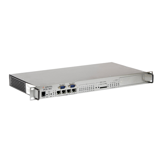
Figure 2. Figure 2 — DCN-16U external and overall dimensions Front panel of DCN-16U with pre-installed DCN-Q4E module and connector and LED indicators is shown in the Figure 3 . Figure 3 – DCN-16U Front panel Note –…
-
Page 14
К1, К2 error relays; − FUSЕ – group of indicators of fuse state: − SYS – status indicator of DCN-16U Main system fuse, installed in main supply voltage circuit 48 V; − EXT – external failure source status indicator;… -
Page 15
DCN-16U EXCHANGE (BASIC VERSION, VERSION WITH PRE-INSTALLED SWITCHING MODULE DCN-Q4E) User Manual Back panel of DCN-16U with connectors and fuses is shown in the Figure 5. Figure 5 – DCN-16U Back panel DCN-16U Back panel contains: terminals for DCN-16U case grounding;… -
Page 16: Product Components Description And Operation
1.2 Product components description and operation 1.2.1 General DCN-16U components are as follows: − DCN-Q4E switching processor module (only in DCN-16U with DCN-Q4E module); − DCN-Q4Е E1 connection cable (only in DCN-16U with DCN-Q4E module); − DCN-16U subscribers connection cable.
-
Page 17
ISDN – physical level specification; − DSS1 – subscriber signaling protocol. In terms of design DCN-Q4E module being a part of DCN-16U Exchange is a printed circuit board to be enclosed into DCN-16U exchange, and powered from its main board. E1 line is connected through DRB-25FA socket on the back panel of the module by means of special cable. -
Page 18: Dcn-Q4E E1 Connection Cable
DCN-Q4Е E1 connection cable is intended for connection to DCN-Q4E switching processor module being a part of DCN-16U exchange, up to four DCN-type exchange units. In addition, it enables to connect digital Exchanges (or other products) by digital E1 lines, but the number of DCN exchanges connected decreases to the number of such products.
-
Page 19: Dcn-16U Subscribers Connection Cable
E1 lines, external error message signal and generating А1, А2 failure signals. The cable is connected to DCN-16U Exchange Back panel through C type DIN41612 socket from one end and from another end it is mounted into 19-inch rack (cabinet) by means of printed circuit board with guides for clamping on DIN-rail 35/7.5.
-
Page 20: Subscriber Units Connected To Dcn-16U (With Dcn-Q4E)
Ones have unified software but different capacities and design. 1.3.2 Digital Exchange (to DCN-16U with DCN-Q4E) External digital Exchange or other device supporting EDSS1 protocol and E1 interface (G.703/G.704). In this case, the number of DCN-16U is reduced by the number of busy interfaces. 1.3.3 Subscriber units…
-
Page 21
DCN-16U EXCHANGE (BASIC VERSION, VERSION WITH PRE-INSTALLED SWITCHING MODULE DCN-Q4E) User Manual DIS call station is manufactured as a desktop version only, DIS-TOP call station can be desktop, wall-mounted and flush-mounted. Depending on version call stations can be additionally equipped with the external… -
Page 22
DCN-16U EXCHANGE (BASIC VERSION, VERSION WITH PRE-INSTALLED SWITCHING MODULE DCN-Q4E) User Manual to the control line to activate any given functions of the central exchange, for example, to start announcement transmission. The module allows for using analogue call stations (for example, the ones made by Neumann Elektronik: WFA, WFAEx, WFK) incorporated into the communication system. -
Page 23: Intended Use
Table 1. 2.1.2 It is forbidden to supply phantom power to products connected to DCN-16U at the same time as main power is supplied to them. 2.1.3 The requirements for operating conditions and the choice of the place of installation given in this document take into account the most typical factors that affect the operation of DCN-16U.
-
Page 24: Safety Precautions
(BASIC VERSION, VERSION WITH PRE-INSTALLED SWITCHING MODULE DCN-Q4E) User Manual 2.3 Safety precautions During installation and operation of DCN-16U, observe safety precautions laid out in local regulations on electrical safety. To avoid electric shock, do not: − operate the product if its case is not connected to the ground rod;…
-
Page 25: Installation, Connection And Dismantling
(BASIC VERSION, VERSION WITH PRE-INSTALLED SWITCHING MODULE DCN-Q4E) User Manual 2.4 Installation, connection and dismantling 2.4.1 Once DCN-16U installed in 19-inch rack (cabinet) using clamps included in scope of supply of rack (cabinet) clamping elements, it should be connected to a patch bay in the following order: −…
-
Page 26: Operation
− Place DCN-16U in consumer packaging. 2.5 Operation 2.5.1 Product On/Off The product is turned on by connecting the voltage of power source to DCN-16U power socket. After initialization DCN-16U functions as follows: − Provides for communication between subscribers according to configuration data;…
-
Page 27: Product General Performance Monitoring Routine
(BASIC VERSION, VERSION WITH PRE-INSTALLED SWITCHING MODULE DCN-Q4E) User Manual 2.5.2 Product general performance monitoring routine Possible states of DCN-16U indicators depending of operation mode are given in Table 3. Table 3 — Possible states of DCN-16U indicators depending of operation mode Indicator…
-
Page 28
DCN-16U EXCHANGE (BASIC VERSION, VERSION WITH PRE-INSTALLED SWITCHING MODULE DCN-Q4E) User Manual Table 3 — Possible states of DCN-16U (with DCN-Q4E) indicators depending of operation mode (continuous) Indicator State Comment DCN-16U Port is not engaged in configuration Port is engaged in configuration, but first… -
Page 29
DCN-16U EXCHANGE (BASIC VERSION, VERSION WITH PRE-INSTALLED SWITCHING MODULE DCN-Q4E) User Manual Table 3 — Possible states of DCN-16U indicators depending of operation mode (end) Indicator State Comment DCN-16U Fuse of phantom power of subscriber units Continuously shine green PoU 5-8 connected to 5-8 channels is OK… -
Page 30: Troubleshooting
DCN-16U don’t glow operability Find the cause, remove the At power on, SYS fuse (48 V) DCN-16U main fuse went cause of trouble and change indicator is red main fuse of DCN-16U Fuse of phantom power supply Find the cause, remove the…
-
Page 31
Subscriber unit connection Change subscriber unit cable is broken connection cable Runtime program loading mode At startup, CPU 1 doesn’t Turn DCN-16U off and on glow CPU didn’t start Load DCN-16U configuration Software is not loaded At startup, CPU 1 is red… -
Page 32: Maintenance
− Remove dust and dirt from product surface. − Check product mounting in the cabinet (rack) and external sockets clampings. − Inspect cables attaching to DCN-16U (it should not be squeezed and damaged). − Check reliability of connection to cable connectors – cables should not be tensed.
-
Page 33: Repair
User Manual 4 REPAIR No scheduled repair work is provided for DCN-16U. Unscheduled repair shall be performed by manufacturer at the request of the User. The place, time, procedure and cost of the work shall be agreed with the manufacturer in advance.
-
Page 34: Storage
(BASIC VERSION, VERSION WITH PRE-INSTALLED SWITCHING MODULE DCN-Q4E) User Manual 5 STORAGE DCN-16U storage conditions are as follows: in item-specific manufacturer’s packaging, heated and ventilated storages or warehouses with air-conditioning with a range of temperature from plus 5 to plus 40 °С.
-
Page 35: Transportation
− the shipping container on the shipping vehicle is fastened to avoid falling and collision. At the same time, transportation of the DCN-16U connection cable and DCN-Q4E E1 connection cable installed in the rack on a DIN-rai is allowed as part of the rack. Measures must be taken to secure the DCN-16 connection cable and the D-SUB-25A connector of the DCN-Q4E E1 connection cable to prevent their free movement.
-
Page 36: Disposal
DCN-16U EXCHANGE (BASIC VERSION, VERSION WITH PRE-INSTALLED SWITCHING MODULE DCN-Q4E) User Manual 7 DISPOSAL The product is not subject to disposal along with daily waste and shall be delivered to a special electronic product disposal facility. Operator is responsible for product disposal.
-
Page 37: Annex А (Reference) Сonnecting Optional Equipment And Power Supply
DCN-16U EXCHANGE (BASIC VERSION, VERSION WITH PRE-INSTALLED SWITCHING MODULE DCN-Q4E) User Manual ANNEX А (REFERENCE) СONNECTING OPTIONAL EQUIPMENT AND POWER SUPPLY А.1 DCN-Q4E E1 connection cable DCN-Q4Е E1 connection cable with overall dimensions is illustrated at Figure А.1. Cable weight is (0,31 ± 0,05) kg.
-
Page 38
DCN-16U EXCHANGE (BASIC VERSION, VERSION WITH PRE-INSTALLED SWITCHING MODULE DCN-Q4E) User Manual Table А.2 – X1 terminal box and RJ-45 pin assignment RJ-45 Socket contact Terminal box contact Signal Assignment Tx 1 Transmission 1 Rx 1 Reception 1 Rx 2… -
Page 39
User Manual − The subscriber unit is not available for DCN-Q4E (line break, unit is faulted/out); − DCN-16U, which connected by E1 line to DCN-Q4E, is not available (line break, DCN-16U is faulted/out); − Other devices, which connected by E1 line to DCN-Q4E, is not available (line break, device is faulted/out). -
Page 40: А.2 Dcn-16U Digital Subscribers Connection Cable
Sys signals generation; 5 – ХТ5 terminal ship for A2 failure signal generation. Figure А.3 – DCN-16U subscribers connection cable DCN-16U subscriber connection cable is connected to DCN-16U exchange back panel through C type DIN41612 socket from one end and from another end it is mounted into 19- inch rack (cabinet) by means of printed circuit board with guides for clamping on DIN-rail 35/7.5.
-
Page 41
DCN-16U EXCHANGE (BASIC VERSION, VERSION WITH PRE-INSTALLED SWITCHING MODULE DCN-Q4E) User Manual Table A.1 – Terminal assignment of XT1 Contact Assignment Contact Assignment Ua1+ Ua9+ Subscriber interface line 1 Subscriber interface line 9 Ub1- Ub9- Ua2+ Ua10+ Subscriber interface line 2… -
Page 42
DCN-16U EXCHANGE (BASIC VERSION, VERSION WITH PRE-INSTALLED SWITCHING MODULE DCN-Q4E) User Manual Terminal assignment of ХT2 is given in the Table A.2. Table A.2 – Terminal assignment of XT2 Contact Assignment Contact Assignment TXb1 TXb3 First Е1 line, transmission Third Е1 line, transmission… -
Page 43: А.3 Connection To Power Supply
User Manual А.3 Connection to power supply First the power cable connects to the “-48 0V GND” socket of DCN-16U (refer to Figure 5), after – to a power source. Power cable socket with pin numbers is shown in the Figure A.4.
-
Page 44: А.4 Phantom Power Supply
3 “GND” of power socket (refer to Figure A.4) and place the jumpers on the contact pairs that corresponds to subscriber units (refer to Figure A.5) 1 – DCN-16U power cable socket; 2 – contact pairs for installation of jumpers 1…16 Ub-; 3 – contact pairs for installation of jampers 1…16 Uа+.
-
Page 45
DCN-16U EXCHANGE (BASIC VERSION, VERSION WITH PRE-INSTALLED SWITCHING MODULE DCN-Q4E) User Manual NOTES armtel.com page 43/44 info@armtel.com © Armtel… -
Page 46
DCN-16U EXCHANGE (BASIC VERSION, VERSION WITH PRE-INSTALLED SWITCHING MODULE DCN-Q4E) User Manual page 44/44 armtel.com © Armtel info@armtel.com… -
Page 47
© Armtel… -
Page 48
ARMTEL LLC Tel./fax: +7 (812) 703-41-11 www.armtel.com | info@armtel.com Legal and physical address: 12 buildung 1, Zaporozhskaya street, office 1/2, Saint Petersburg, 192012 TECHNICAL SUPPORT 8-800-500-90-17 (for calls from Russian Federation) +7-812-633-04-02 (for international calls) support@armtel.com MORE INFORMATION ABOUT PRODUCT ON OFFICIAL SITE…
Download or browse on-line these Operation & User’s Manual for ARMTEL DCN-16U Switch.
Summary of Contents:
 |
[Page 1] ARMTEL DCN-16U DCN-16U Exchange (basic version, version with pre-installed switching module DCN-Q4E) ARMT.665200.001UM User Manual Document version 17-11 2… |
 |
[Page 3] ARMTEL DCN-16U DCN-16U EXCHANGE (BASIC VERSION, VERSION WITH PRE-INSTALLED SWITCHING MODULE DCN-Q4E) User Manual armtel.com page 1/44 [email protected] © Armtel INTRODUCTION This User Manual is intended for introducing DCN-16U Exchange of ARMT.665200…. |
 |
[Page 4] ARMTEL DCN-16U DCN-16U EXCHANGE (BASIC VERSION, VERSION WITH PRE-INSTALLED SWITCHING MODULE DCN-Q4E) User Manual page 2/44 armtel.com © Armtel [email protected] SAFETY PROVISIONS During installation and operation of DCN-16U, observe safety precaution… |
 |
[Page 5] ARMTEL DCN-16U DCN-16U EXCHANGE (BASIC VERSION, VERSION WITH PRE-INSTALLED SWITCHING MODULE DCN-Q4E) User Manual armtel.com page 3/44 [email protected] © Armtel CONTENTS INTRODUCTION ……………………………………………………………. |
 |
[Page 6] ARMTEL DCN-16U DCN-16U EXCHANGE (BASIC VERSION, VERSION WITH PRE-INSTALLED SWITCHING MODULE DCN-Q4E) User Manual page 4/44 armtel.com © Armtel [email protected] 7 DISPOSAL ………………………………………………………………………. |
 |
[Page 7] ARMTEL DCN-16U DCN-16U EXCHANGE (BASIC VERSION, VERSION WITH PRE-INSTALLED SWITCHING MODULE DCN-Q4E) User Manual armtel.com page 5/44 [email protected] © Armtel 1 DESCRIPTION AND OPERATION 1.1 Product description and operation 1.1.1 Functions DCN-1… |
 |
[Page 8] ARMTEL DCN-16U DCN-16U EXCHANGE (BASIC VERSION, VERSION WITH PRE-INSTALLED SWITCHING MODULE DCN-Q4E) User Manual page 6/44 armtel.com © Armtel [email protected] a) version ARMT.665200.001 (base version) b) version ARMT.665200.001-01 (with pre-ins… |
 |
[Page 9] ARMTEL DCN-16U DCN-16U EXCHANGE (BASIC VERSION, VERSION WITH PRE-INSTALLED SWITCHING MODULE DCN-Q4E) User Manual armtel.com page 7/44 [email protected] © Armtel Being a part of DCN digital intercom system DCN-16U exchange functions as follows: − C… |
 |
[Page 10] ARMTEL DCN-16U DCN-16U EXCHANGE (BASIC VERSION, VERSION WITH PRE-INSTALLED SWITCHING MODULE DCN-Q4E) User Manual page 8/44 armtel.com © Armtel [email protected] − E1 (G.703/G.704) – for connection to DCN system central exchange via E1 line. Uk0 … |
 |
[Page 11] ARMTEL DCN-16U DCN-16U EXCHANGE (BASIC VERSION, VERSION WITH PRE-INSTALLED SWITCHING MODULE DCN-Q4E) User Manual armtel.com page 9/44 [email protected] © Armtel Table 1 – Main specifications Parameter Value Rated voltage, V -48 Supply voltage… |
 |
[Page 12] ARMTEL DCN-16U DCN-16U EXCHANGE (BASIC VERSION, VERSION WITH PRE-INSTALLED SWITCHING MODULE DCN-Q4E) User Manual page 10/44 armtel.com © Armtel [email protected] 1.1.3 Scope of supply Scope of supply for DCN-16U is given in the Table 2. Table 2 – … |
 |
[Page 13] ARMTEL DCN-16U DCN-16U EXCHANGE (BASIC VERSION, VERSION WITH PRE-INSTALLED SWITCHING MODULE DCN-Q4E) User Manual armtel.com page 11/44 [email protected] © Armtel 1.1.4 Design DCN-16U Exchange mounted into a 19-inch rack (cabinet). DCN-16U external an… |
 |
[Page 14] ARMTEL DCN-16U DCN-16U EXCHANGE (BASIC VERSION, VERSION WITH PRE-INSTALLED SWITCHING MODULE DCN-Q4E) User Manual page 12/44 armtel.com © Armtel [email protected] − 1…4 – indicators of 1…4 E1 line connection status. During operation indicator … |
 |
[Page 15] ARMTEL DCN-16U DCN-16U EXCHANGE (BASIC VERSION, VERSION WITH PRE-INSTALLED SWITCHING MODULE DCN-Q4E) User Manual armtel.com page 13/44 [email protected] © Armtel Back panel of DCN-16U with connectors and fuses is shown in the Figure 5. Figure 5 –… |
 |
[Page 16] ARMTEL DCN-16U DCN-16U EXCHANGE (BASIC VERSION, VERSION WITH PRE-INSTALLED SWITCHING MODULE DCN-Q4E) User Manual page 14/44 armtel.com © Armtel [email protected] 1.2 Product components description and operation 1.2.1 General DCN-16U components are a… |
 |
[Page 17] ARMTEL DCN-16U DCN-16U EXCHANGE (BASIC VERSION, VERSION WITH PRE-INSTALLED SWITCHING MODULE DCN-Q4E) User Manual armtel.com page 15/44 [email protected] © Armtel − connection of external Exchanges to DCN communication system by ISDN PRI lines; �… |
 |
[Page 18] ARMTEL DCN-16U DCN-16U EXCHANGE (BASIC VERSION, VERSION WITH PRE-INSTALLED SWITCHING MODULE DCN-Q4E) User Manual page 16/44 armtel.com © Armtel [email protected] The Figure 6 shows DCN-Q4E module board with overall dimensions. Figure 6 – DCN-Q4E … |
 |
[Page 19] ARMTEL DCN-16U DCN-16U EXCHANGE (BASIC VERSION, VERSION WITH PRE-INSTALLED SWITCHING MODULE DCN-Q4E) User Manual armtel.com page 17/44 [email protected] © Armtel board with 35/7.5 DIN-rail mountable guides is installed into 19 inch rack. Cable view wi… |
 |
[Page 20] ARMTEL DCN-16U DCN-16U EXCHANGE (BASIC VERSION, VERSION WITH PRE-INSTALLED SWITCHING MODULE DCN-Q4E) User Manual page 18/44 armtel.com © Armtel [email protected] 1.3 Subscriber units connected to DCN-16U (with DCN-Q4E) 1.3.1 General information Loud… |
 |
[Page 21] ARMTEL DCN-16U DCN-16U EXCHANGE (BASIC VERSION, VERSION WITH PRE-INSTALLED SWITCHING MODULE DCN-Q4E) User Manual armtel.com page 19/44 [email protected] © Armtel DIS call station is manufactured as a desktop version only, DIS-TOP call station can be … |
 |
[Page 22] ARMTEL DCN-16U DCN-16U EXCHANGE (BASIC VERSION, VERSION WITH PRE-INSTALLED SWITCHING MODULE DCN-Q4E) User Manual page 20/44 armtel.com © Armtel [email protected] to the control line to activate any given functions of the central exchange, for example,… |
 |
[Page 23] ARMTEL DCN-16U DCN-16U EXCHANGE (BASIC VERSION, VERSION WITH PRE-INSTALLED SWITCHING MODULE DCN-Q4E) User Manual armtel.com page 21/44 [email protected] © Armtel 2 INTENDED USE The product is designed for continuous 24-hour a day operations. After c… |
 |
[Page 24] ARMTEL DCN-16U DCN-16U EXCHANGE (BASIC VERSION, VERSION WITH PRE-INSTALLED SWITCHING MODULE DCN-Q4E) User Manual page 22/44 armtel.com © Armtel [email protected] 2.3 Safety precautions During installation and operation of DCN-16U, observe safety prec… |
 |
[Page 25] ARMTEL DCN-16U DCN-16U EXCHANGE (BASIC VERSION, VERSION WITH PRE-INSTALLED SWITCHING MODULE DCN-Q4E) User Manual armtel.com page 23/44 [email protected] © Armtel 2.4 Installation, connection and dismantling 2.4.1 Once DCN-16U installed in 19-inch rac… |
 |
[Page 26] ARMTEL DCN-16U DCN-16U EXCHANGE (BASIC VERSION, VERSION WITH PRE-INSTALLED SWITCHING MODULE DCN-Q4E) User Manual page 24/44 armtel.com © Armtel [email protected] 2.4.4 Dismantling: − Turn off the power source and disconnect the power socket. − … |
 |
[Page 27] ARMTEL DCN-16U DCN-16U EXCHANGE (BASIC VERSION, VERSION WITH PRE-INSTALLED SWITCHING MODULE DCN-Q4E) User Manual armtel.com page 25/44 [email protected] © Armtel 2.5.2 Product general performance monitoring routine Possible states of DCN-16U indicato… |
 |
[Page 28] ARMTEL DCN-16U DCN-16U EXCHANGE (BASIC VERSION, VERSION WITH PRE-INSTALLED SWITCHING MODULE DCN-Q4E) User Manual page 26/44 armtel.com © Armtel [email protected] Table 3 — Possible states of DCN-16U (with DCN-Q4E) indicators depending of operation mo… |
 |
[Page 29] ARMTEL DCN-16U DCN-16U EXCHANGE (BASIC VERSION, VERSION WITH PRE-INSTALLED SWITCHING MODULE DCN-Q4E) User Manual armtel.com page 27/44 [email protected] © Armtel Table 3 — Possible states of DCN-16U indicators depending of operation mode (end) I… |
 |
[Page 30] ARMTEL DCN-16U DCN-16U EXCHANGE (BASIC VERSION, VERSION WITH PRE-INSTALLED SWITCHING MODULE DCN-Q4E) User Manual page 28/44 armtel.com © Armtel [email protected] 2.5.3 Troubleshooting Possible problems and their solutions are given in Table 4. Table… |
 |
[Page 31] ARMTEL DCN-16U DCN-16U EXCHANGE (BASIC VERSION, VERSION WITH PRE-INSTALLED SWITCHING MODULE DCN-Q4E) User Manual armtel.com page 29/44 [email protected] © Armtel Table 4 – Possible problems and their solutions (end) Problem Possible cause Soluti… |
 |
[Page 32] ARMTEL DCN-16U DCN-16U EXCHANGE (BASIC VERSION, VERSION WITH PRE-INSTALLED SWITCHING MODULE DCN-Q4E) User Manual page 30/44 armtel.com © Armtel [email protected] 3 MAINTENANCE Maintenance shall be carried out to ensure the module fault-free performan… |
 |
[Page 33] ARMTEL DCN-16U DCN-16U EXCHANGE (BASIC VERSION, VERSION WITH PRE-INSTALLED SWITCHING MODULE DCN-Q4E) User Manual armtel.com page 31/44 [email protected] © Armtel 4 REPAIR No scheduled repair work is provided for DCN-16U. Unscheduled repair shall be … |
 |
[Page 34] ARMTEL DCN-16U DCN-16U EXCHANGE (BASIC VERSION, VERSION WITH PRE-INSTALLED SWITCHING MODULE DCN-Q4E) User Manual page 32/44 armtel.com © Armtel [email protected] 5 STORAGE DCN-16U storage conditions are as follows: in item-specific manufacturer’s p… |
 |
[Page 35] ARMTEL DCN-16U DCN-16U EXCHANGE (BASIC VERSION, VERSION WITH PRE-INSTALLED SWITCHING MODULE DCN-Q4E) User Manual armtel.com page 33/44 [email protected] © Armtel 6 TRANSPORTATION The product shall be transported in customer package as a packaging uni… |
 |
[Page 36] ARMTEL DCN-16U DCN-16U EXCHANGE (BASIC VERSION, VERSION WITH PRE-INSTALLED SWITCHING MODULE DCN-Q4E) User Manual page 34/44 armtel.com © Armtel [email protected] 7 DISPOSAL The product is not subject to disposal along with daily waste and shall be de… |
 |
[Page 37] ARMTEL DCN-16U DCN-16U EXCHANGE (BASIC VERSION, VERSION WITH PRE-INSTALLED SWITCHING MODULE DCN-Q4E) User Manual armtel.com page 35/44 [email protected] © Armtel ANNEX А (REFERENCE) СONNECTING OPTIONAL EQUIPMENT AND POWER SUPPLY А.1 DCN-Q4E E1 c… |
 |
[Page 38] ARMTEL DCN-16U DCN-16U EXCHANGE (BASIC VERSION, VERSION WITH PRE-INSTALLED SWITCHING MODULE DCN-Q4E) User Manual page 36/44 armtel.com © Armtel [email protected] Table А.2 – X1 terminal box and RJ-45 pin assignment RJ-45 Socket contact Terminal… |
 |
[Page 39] ARMTEL DCN-16U DCN-16U EXCHANGE (BASIC VERSION, VERSION WITH PRE-INSTALLED SWITCHING MODULE DCN-Q4E) User Manual armtel.com page 37/44 [email protected] © Armtel − The subscriber unit is not available for DCN-Q4E (line break, unit is faulted/out); … |
 |
[Page 40] ARMTEL DCN-16U DCN-16U EXCHANGE (BASIC VERSION, VERSION WITH PRE-INSTALLED SWITCHING MODULE DCN-Q4E) User Manual page 38/44 armtel.com © Armtel [email protected] А.2 DCN-16U digital subscribers connection cable DCN-16U subscriber connection cable wi… |
 |
[Page 41] ARMTEL DCN-16U DCN-16U EXCHANGE (BASIC VERSION, VERSION WITH PRE-INSTALLED SWITCHING MODULE DCN-Q4E) User Manual armtel.com page 39/44 [email protected] © Armtel Table A.1 – Terminal assignment of XT1 Contact Assignment Contact Assignment Ua1+ … |
 |
[Page 42] ARMTEL DCN-16U DCN-16U EXCHANGE (BASIC VERSION, VERSION WITH PRE-INSTALLED SWITCHING MODULE DCN-Q4E) User Manual page 40/44 armtel.com © Armtel [email protected] Terminal assignment of ХT2 is given in the Table A.2. Table A.2 – Terminal assignment… |
 |
[Page 43] ARMTEL DCN-16U DCN-16U EXCHANGE (BASIC VERSION, VERSION WITH PRE-INSTALLED SWITCHING MODULE DCN-Q4E) User Manual armtel.com page 41/44 [email protected] © Armtel А.3 Connection to power supply First the power cable connects to the “-48 0V GND”… |
 |
[Page 44] ARMTEL DCN-16U DCN-16U EXCHANGE (BASIC VERSION, VERSION WITH PRE-INSTALLED SWITCHING MODULE DCN-Q4E) User Manual page 42/44 armtel.com © Armtel [email protected] А.4 Phantom power supply In order to supply phantom power to subscriber units it is nec… |
 |
[Page 45] ARMTEL DCN-16U DCN-16U EXCHANGE (BASIC VERSION, VERSION WITH PRE-INSTALLED SWITCHING MODULE DCN-Q4E) User Manual armtel.com page 43/44 [email protected] © Armtel NOTES |
 |
[Page 46] ARMTEL DCN-16U DCN-16U EXCHANGE (BASIC VERSION, VERSION WITH PRE-INSTALLED SWITCHING MODULE DCN-Q4E) User Manual page 44/44 armtel.com © Armtel [email protected] |
 |
[Page 48] ARMTEL DCN-16U ARMTEL LLC Tel./fax: +7 (812) 703-41-11 www.armtel.com | [email protected] Legal and physical address: 12 buildung 1, Zaporozhskaya street, office 1/2, Saint Petersburg, 192012 TECHNICAL SUPPORT 8-800-500-90-17 (for calls from Russian Federation) +7-… |
-
Page 1
DCN-16U Exchange (basic version, version with pre-installed switching module DCN-Q4E) ARMT.665200.001UM User Manual Document version 17-11 26.30.11.190 2020… -
Page 2
© Armtel info@armtel.com… -
Page 3: Introduction
ARMT.665200.001-01 with pre-installed switching processor module DCN-Q4E (4xE1) ARMT.665200.010 to the User. DCN-16U exchange is a compact connection unit for subscriber equipment within the DCN distributed of Public Address and General Alarm system. Short product name – DCN-16U.
-
Page 4: Safety Provisions
(BASIC VERSION, VERSION WITH PRE-INSTALLED SWITCHING MODULE DCN-Q4E) User Manual SAFETY PROVISIONS During installation and operation of DCN-16U, observe safety precautions laid out in local regulations on electrical safety. To avoid electric shock, do not: − operate the product if its case is not connected to the ground rod;…
-
Page 5: Table Of Contents
1.2.4 DCN-16U subscribers connection cable ………………..17 1.3 Subscriber units connected to DCN-16U (with DCN-Q4E) …………..18 1.3.1 General information ………………………. 18 1.3.2 DCN-2 Exchange / DCN-Q4E switching processor module (to DCN-16U with DCN-Q4E) ……………………………. 18 1.3.2 Digital ATX (to DCN-16U with DCN-Q4E) ………………18 1.3.3 Subscriber units ……………………….
-
Page 6
7 DISPOSAL …………………………….. 34 ANNEX А (reference) Сonnecting optional equipment and power supply ……….35 А.1 DCN-Q4E E1 connection cable ……………………35 А.2 DCN-16U digital subscribers connection cable ………………38 А.3 Connection to power supply ……………………..41 А.4 Phantom power supply ……………………….42 page 4/44 armtel.com… -
Page 7: Description And Operation
Therefore, maximum capacity of DCN-Q4E-based system can be up to 60 subscribers. The switching processor module DCN-Q4E intended for use as central exchange unit of DCN system, at the enterprise of industry and transport. DCN system (Armtel LLC) built with product provide simplex communication between loud-speaking subscriber devices manufactured by Armtel LLC, duplex communication with telephony subscribers, paging, and emergency loud warning.
-
Page 8
Armtel subscriber units, an expanded sound transmit frequency band of 6.8 kHz is used. DCN-16U is connected to a central exchange of DCN system by E1 line, which is used for transmitting voice traffic channels and signaling between the central exchange and subscriber units. -
Page 9: Main Specifications
DCN-16U Exchange is ready for operation as supplied and no programming is required during operation except for assignment of subscriber unit connection ports. Operation of DCN-16U Exchange and subscriber units connected to it is managed by a central exchange of DCN system connected to DCN-16U via E1 line.
-
Page 10
− I.432 of recommendations of ITU-T (ISDN standard) – User-network interface B- ISDN – physical level specification; − DSS1 – subscriber signaling protocol. Main specifications and performance characteristics of DCN-16U Exchange are given in the Table 1. page 8/44 armtel.com ©… -
Page 11
Conditioned locations or partially conditioned air. The product enables/disables the configured subscriber units without power shutdown and reboot. DCN-16U has protection against incorrect polarity of power supply connection. ATTENTION: WHEN CONNECTING PHANTOM POWER ADHERENCE TO INSTRUCTIONS OF MANUALS FOR CONNECTED SUBSCRIBER UNITS IS SCTRICTLY… -
Page 12: Scope Of Supply
DCN-16U EXCHANGE (BASIC VERSION, VERSION WITH PRE-INSTALLED SWITCHING MODULE DCN-Q4E) User Manual 1.1.3 Scope of supply Scope of supply for DCN-16U is given in the Table 2. Table 2 – Scope of supply Quantity, Identification Name Note pcs. ARMT.665200.001* DCN-16U Exchange Additional information on scope of supply ARMT.665200.102…
-
Page 13: Design
Figure 2. Figure 2 — DCN-16U external and overall dimensions Front panel of DCN-16U with pre-installed DCN-Q4E module and connector and LED indicators is shown in the Figure 3 . Figure 3 – DCN-16U Front panel Note –…
-
Page 14
К1, К2 error relays; − FUSЕ – group of indicators of fuse state: − SYS – status indicator of DCN-16U Main system fuse, installed in main supply voltage circuit 48 V; − EXT – external failure source status indicator;… -
Page 15
DCN-16U EXCHANGE (BASIC VERSION, VERSION WITH PRE-INSTALLED SWITCHING MODULE DCN-Q4E) User Manual Back panel of DCN-16U with connectors and fuses is shown in the Figure 5. Figure 5 – DCN-16U Back panel DCN-16U Back panel contains: terminals for DCN-16U case grounding;… -
Page 16: Product Components Description And Operation
1.2 Product components description and operation 1.2.1 General DCN-16U components are as follows: − DCN-Q4E switching processor module (only in DCN-16U with DCN-Q4E module); − DCN-Q4Е E1 connection cable (only in DCN-16U with DCN-Q4E module); − DCN-16U subscribers connection cable.
-
Page 17
ISDN – physical level specification; − DSS1 – subscriber signaling protocol. In terms of design DCN-Q4E module being a part of DCN-16U Exchange is a printed circuit board to be enclosed into DCN-16U exchange, and powered from its main board. E1 line is connected through DRB-25FA socket on the back panel of the module by means of special cable. -
Page 18: Dcn-Q4E E1 Connection Cable
DCN-Q4Е E1 connection cable is intended for connection to DCN-Q4E switching processor module being a part of DCN-16U exchange, up to four DCN-type exchange units. In addition, it enables to connect digital Exchanges (or other products) by digital E1 lines, but the number of DCN exchanges connected decreases to the number of such products.
-
Page 19: Dcn-16U Subscribers Connection Cable
E1 lines, external error message signal and generating А1, А2 failure signals. The cable is connected to DCN-16U Exchange Back panel through C type DIN41612 socket from one end and from another end it is mounted into 19-inch rack (cabinet) by means of printed circuit board with guides for clamping on DIN-rail 35/7.5.
-
Page 20: Subscriber Units Connected To Dcn-16U (With Dcn-Q4E)
Ones have unified software but different capacities and design. 1.3.2 Digital Exchange (to DCN-16U with DCN-Q4E) External digital Exchange or other device supporting EDSS1 protocol and E1 interface (G.703/G.704). In this case, the number of DCN-16U is reduced by the number of busy interfaces. 1.3.3 Subscriber units…
-
Page 21
DCN-16U EXCHANGE (BASIC VERSION, VERSION WITH PRE-INSTALLED SWITCHING MODULE DCN-Q4E) User Manual DIS call station is manufactured as a desktop version only, DIS-TOP call station can be desktop, wall-mounted and flush-mounted. Depending on version call stations can be additionally equipped with the external… -
Page 22
DCN-16U EXCHANGE (BASIC VERSION, VERSION WITH PRE-INSTALLED SWITCHING MODULE DCN-Q4E) User Manual to the control line to activate any given functions of the central exchange, for example, to start announcement transmission. The module allows for using analogue call stations (for example, the ones made by Neumann Elektronik: WFA, WFAEx, WFK) incorporated into the communication system. -
Page 23: Intended Use
Table 1. 2.1.2 It is forbidden to supply phantom power to products connected to DCN-16U at the same time as main power is supplied to them. 2.1.3 The requirements for operating conditions and the choice of the place of installation given in this document take into account the most typical factors that affect the operation of DCN-16U.
-
Page 24: Safety Precautions
(BASIC VERSION, VERSION WITH PRE-INSTALLED SWITCHING MODULE DCN-Q4E) User Manual 2.3 Safety precautions During installation and operation of DCN-16U, observe safety precautions laid out in local regulations on electrical safety. To avoid electric shock, do not: − operate the product if its case is not connected to the ground rod;…
-
Page 25: Installation, Connection And Dismantling
(BASIC VERSION, VERSION WITH PRE-INSTALLED SWITCHING MODULE DCN-Q4E) User Manual 2.4 Installation, connection and dismantling 2.4.1 Once DCN-16U installed in 19-inch rack (cabinet) using clamps included in scope of supply of rack (cabinet) clamping elements, it should be connected to a patch bay in the following order: −…
-
Page 26: Operation
− Place DCN-16U in consumer packaging. 2.5 Operation 2.5.1 Product On/Off The product is turned on by connecting the voltage of power source to DCN-16U power socket. After initialization DCN-16U functions as follows: − Provides for communication between subscribers according to configuration data;…
-
Page 27: Product General Performance Monitoring Routine
(BASIC VERSION, VERSION WITH PRE-INSTALLED SWITCHING MODULE DCN-Q4E) User Manual 2.5.2 Product general performance monitoring routine Possible states of DCN-16U indicators depending of operation mode are given in Table 3. Table 3 — Possible states of DCN-16U indicators depending of operation mode Indicator…
-
Page 28
DCN-16U EXCHANGE (BASIC VERSION, VERSION WITH PRE-INSTALLED SWITCHING MODULE DCN-Q4E) User Manual Table 3 — Possible states of DCN-16U (with DCN-Q4E) indicators depending of operation mode (continuous) Indicator State Comment DCN-16U Port is not engaged in configuration Port is engaged in configuration, but first… -
Page 29
DCN-16U EXCHANGE (BASIC VERSION, VERSION WITH PRE-INSTALLED SWITCHING MODULE DCN-Q4E) User Manual Table 3 — Possible states of DCN-16U indicators depending of operation mode (end) Indicator State Comment DCN-16U Fuse of phantom power of subscriber units Continuously shine green PoU 5-8 connected to 5-8 channels is OK… -
Page 30: Troubleshooting
DCN-16U don’t glow operability Find the cause, remove the At power on, SYS fuse (48 V) DCN-16U main fuse went cause of trouble and change indicator is red main fuse of DCN-16U Fuse of phantom power supply Find the cause, remove the…
-
Page 31
Subscriber unit connection Change subscriber unit cable is broken connection cable Runtime program loading mode At startup, CPU 1 doesn’t Turn DCN-16U off and on glow CPU didn’t start Load DCN-16U configuration Software is not loaded At startup, CPU 1 is red… -
Page 32: Maintenance
− Remove dust and dirt from product surface. − Check product mounting in the cabinet (rack) and external sockets clampings. − Inspect cables attaching to DCN-16U (it should not be squeezed and damaged). − Check reliability of connection to cable connectors – cables should not be tensed.
-
Page 33: Repair
User Manual 4 REPAIR No scheduled repair work is provided for DCN-16U. Unscheduled repair shall be performed by manufacturer at the request of the User. The place, time, procedure and cost of the work shall be agreed with the manufacturer in advance.
-
Page 34: Storage
(BASIC VERSION, VERSION WITH PRE-INSTALLED SWITCHING MODULE DCN-Q4E) User Manual 5 STORAGE DCN-16U storage conditions are as follows: in item-specific manufacturer’s packaging, heated and ventilated storages or warehouses with air-conditioning with a range of temperature from plus 5 to plus 40 °С.
-
Page 35: Transportation
− the shipping container on the shipping vehicle is fastened to avoid falling and collision. At the same time, transportation of the DCN-16U connection cable and DCN-Q4E E1 connection cable installed in the rack on a DIN-rai is allowed as part of the rack. Measures must be taken to secure the DCN-16 connection cable and the D-SUB-25A connector of the DCN-Q4E E1 connection cable to prevent their free movement.
-
Page 36: Disposal
DCN-16U EXCHANGE (BASIC VERSION, VERSION WITH PRE-INSTALLED SWITCHING MODULE DCN-Q4E) User Manual 7 DISPOSAL The product is not subject to disposal along with daily waste and shall be delivered to a special electronic product disposal facility. Operator is responsible for product disposal.
-
Page 37: Annex А (Reference) Сonnecting Optional Equipment And Power Supply
DCN-16U EXCHANGE (BASIC VERSION, VERSION WITH PRE-INSTALLED SWITCHING MODULE DCN-Q4E) User Manual ANNEX А (REFERENCE) СONNECTING OPTIONAL EQUIPMENT AND POWER SUPPLY А.1 DCN-Q4E E1 connection cable DCN-Q4Е E1 connection cable with overall dimensions is illustrated at Figure А.1. Cable weight is (0,31 ± 0,05) kg.
-
Page 38
DCN-16U EXCHANGE (BASIC VERSION, VERSION WITH PRE-INSTALLED SWITCHING MODULE DCN-Q4E) User Manual Table А.2 – X1 terminal box and RJ-45 pin assignment RJ-45 Socket contact Terminal box contact Signal Assignment Tx 1 Transmission 1 Rx 1 Reception 1 Rx 2… -
Page 39
User Manual − The subscriber unit is not available for DCN-Q4E (line break, unit is faulted/out); − DCN-16U, which connected by E1 line to DCN-Q4E, is not available (line break, DCN-16U is faulted/out); − Other devices, which connected by E1 line to DCN-Q4E, is not available (line break, device is faulted/out). -
Page 40: А.2 Dcn-16U Digital Subscribers Connection Cable
Sys signals generation; 5 – ХТ5 terminal ship for A2 failure signal generation. Figure А.3 – DCN-16U subscribers connection cable DCN-16U subscriber connection cable is connected to DCN-16U exchange back panel through C type DIN41612 socket from one end and from another end it is mounted into 19- inch rack (cabinet) by means of printed circuit board with guides for clamping on DIN-rail 35/7.5.
-
Page 41
DCN-16U EXCHANGE (BASIC VERSION, VERSION WITH PRE-INSTALLED SWITCHING MODULE DCN-Q4E) User Manual Table A.1 – Terminal assignment of XT1 Contact Assignment Contact Assignment Ua1+ Ua9+ Subscriber interface line 1 Subscriber interface line 9 Ub1- Ub9- Ua2+ Ua10+ Subscriber interface line 2… -
Page 42
DCN-16U EXCHANGE (BASIC VERSION, VERSION WITH PRE-INSTALLED SWITCHING MODULE DCN-Q4E) User Manual Terminal assignment of ХT2 is given in the Table A.2. Table A.2 – Terminal assignment of XT2 Contact Assignment Contact Assignment TXb1 TXb3 First Е1 line, transmission Third Е1 line, transmission… -
Page 43: А.3 Connection To Power Supply
User Manual А.3 Connection to power supply First the power cable connects to the “-48 0V GND” socket of DCN-16U (refer to Figure 5), after – to a power source. Power cable socket with pin numbers is shown in the Figure A.4.
-
Page 44: А.4 Phantom Power Supply
3 “GND” of power socket (refer to Figure A.4) and place the jumpers on the contact pairs that corresponds to subscriber units (refer to Figure A.5) 1 – DCN-16U power cable socket; 2 – contact pairs for installation of jumpers 1…16 Ub-; 3 – contact pairs for installation of jampers 1…16 Uа+.
-
Page 45
DCN-16U EXCHANGE (BASIC VERSION, VERSION WITH PRE-INSTALLED SWITCHING MODULE DCN-Q4E) User Manual NOTES armtel.com page 43/44 info@armtel.com © Armtel… -
Page 46
DCN-16U EXCHANGE (BASIC VERSION, VERSION WITH PRE-INSTALLED SWITCHING MODULE DCN-Q4E) User Manual page 44/44 armtel.com © Armtel info@armtel.com… -
Page 47
© Armtel… -
Page 48
ARMTEL LLC Tel./fax: +7 (812) 703-41-11 www.armtel.com | info@armtel.com Legal and physical address: 12 buildung 1, Zaporozhskaya street, office 1/2, Saint Petersburg, 192012 TECHNICAL SUPPORT 8-800-500-90-17 (for calls from Russian Federation) +7-812-633-04-02 (for international calls) support@armtel.com MORE INFORMATION ABOUT PRODUCT ON OFFICIAL SITE…
2.4.1 Once DCN-16U installed in 19-inch rack (cabinet) using clamps included in scope
of supply of rack (cabinet) clamping elements, it should be connected to a patch bay in the
following order:
− connect a grounding wire, made as per IEC, to earthing terminal
panel of DCN-16U. Protective earthing and as well as grounding arrangement
shall meet the IEC requirements. Manufacturer recommendation for grounding
wire: cross section of at least 0,5 mm
at least 7 mm;
Note – Grounding wire is not included in the scope of supply.
− connect the socket of DCN-16U subscriber connection cable to the plug
DIN41612С-64М DCN-16U. Clamp cable board in a DIN-rail mounted in
the rack (cabinet);
− plug DCN-Q4E E1 cable connector into the module DRB-25FA socket. Clamp
cable board in the DIN-rail mounted in the 19-inch rack (for version DCN-16U
with pre-installed DCN-Q4E module).
− connect supply voltage wires to three-pin power socket and connect it
to DCN-16U Exchange plug with power source being off. Power cable socket
with pin numbers is shown in the Annex A.
2.4.2 DCN-16U is connected to DCN central Exchange via E1 line
out by means of UTP-type four-core cable, which is connected to the contacts of XT2
terminal strip of DCN-16U subscribers connection cable from one end, and from another
end to the sockets of DCN-2 E1 or DCN-Q4E connection cable. The cable can also be crimped
with RJ-45 connector from another end for connecting to RJ-45 socket located on the DCN
connection cable board or for connecting to patch bays or network equipment of third-party
manufacturers.
2.4.3 Lines of communication with end subscriber units shall be connected to
the terminal strips of DCN-16U subscribers connection cable board according to general
layout of the communication system.
2.4.3 Connect E1 line of communication with additional DCN-16U Exchanges or
DCN-15A analogue inter-face modules to terminal strips of DCN-Q4E E1 connection cable
board.
armtel.com
info@armtel.com
(BASIC VERSION, VERSION WITH PRE-INSTALLED SWITCHING MODULE DCN-Q4E)
with a tab with an outer diameter of
2
.
DCN-16U EXCHANGE
User Manual
on the Back
Connection is carried
page
23/44
© Armtel

- Описание
-
НАЗНАЧЕНИЕ
Коммутатор DCN-16U предназначен для орагнизации Система промышленной связи DCN построена на коммутаторах DCN-16U по модульному принципу. Каждый модуль представляет собой цифровой коммутатор с шестнадцатью интерфейсами, к которым возможно подключение цифровых переговорных устройств, аналоговых переговорных
устройств, а также трансляционных усилителей с помощью модуля аналоговых подсистем (МАП). Для улучшения качества громкоговорящей связи в DCN-16U используется расширенная полоса частот передачи звука − 6,8 кГц (в обычных цифровых телефонных станциях 3,4 кГц).Цифровые и аналоговые переговорные устройства,подключаемые с помощью МАП, работают с полосой 6,8 кГц.
Система имеет сквозную трехзначную нумерацию, то есть каждому абоненту в такой системе присваивается уникальный абонентский номер.
ФУНКЦИИ
- организация симплексной громкоговорящей связи между подключенными к нему абонентскими устройствами
- возможность индивидуального вызова любого абонента или группы абонентов (для аппаратов с номеронабирателем)
- индивидуальное оповещение абонентов по громкоговорящей связи
- зональное (групповое) оповещение абонентов по громкоговорящей связи
- свободная нумерация абонентов
- приоритетный порядок вызова абонентов
- возможность произвольного назначения приоритетов соединения
- запись звукового сообщения в автоиноформатор и его контрольное воспроизведение
- ручное или автоматическое транслирование сигналов тревоги, оповещения, сообщений, записанных в автоинформатор
- подключение DCN-16U к внешним станциям по потоку Е1. В качестве оконечного оборудования необходимо использовать ISDN телефоны
- локальный контроль, диагностика и конфигурирование системы c АРМ администратора
- Tехнические данные
-
ТЕХНИЧЕСКИЕ ХАРАКТЕРИСТИКИ КОММУТАТОРА DCN-16U
Наименование параметра Величина Номинальное напряжение питания от внешнего источника по ГОСТ 5237-88 48 В Напряжение питания от 36 до 60 В Напряжение радиопомех в сети электропитания по ГОСТ В 25803-91 1.1.2 группа Потребляемая мощность, не более 20 Вт Атмосферное давление от 86 до106 кПа Класс электрозащиты по ГОСТ 12.2.007.0-75 II Степень защиты от проникновения посторонних веществ и воды по ГОСТ 14254-96 IP 40 Относительная влажность воздуха при температуре от 20 °С до 25 °С от 20 до 95% Диапазон допустимых значений температуры окружающего воздуха от — 5 до + 55 °С Размеры корпуса 483 x 227 x 44 мм Вес, не более 2,7 кг МОДУЛЬ АВТОИНФОРМАТОРА DCN-SD
Модуль автоинформатора DCN-SD коммутатора DCN-16U предназначен для записи и воспроизведения аудио информации.
Одновременных каналов записи — один, воспроизведения — шесть при 6,8 кГц и три при 16 кГц. Он оборудован устройством чтения/записи карт SD/MMC.КОММУТАЦИОННЫЙ ПРОЦЕССОРНЫЙ МОДУЛЬ DCN-Q4E
DCN-Q4E предназначен для подключения к нему до четырех коммутаторов типа DCN в составе
системы многофункциональной промышленной связи DCN для организации симплексной и
дуплексной связи и громкого оповещения. Кроме того, он обеспечивает подключение цифровых
АТС (или других изделий, использующих цифровые потоки Е1) по цифровым потокам Е1, но
количество коммутаторов типа DCN при этом уменьшается на количество АТС. - Документация