- Manuals
- Brands
- Asus Manuals
- Motherboard
- PRIME Z490M-PLUS
- Manual
-
Contents
-
Table of Contents
-
Bookmarks
Quick Links
Related Manuals for Asus PRIME Z490M-PLUS
Summary of Contents for Asus PRIME Z490M-PLUS
-
Page 1
PRIME Z490M-PLUS… -
Page 2
Product warranty or service will not be extended if: (1) the product is repaired, modified or altered, unless such repair, modification of alteration is authorized in writing by ASUS; or (2) the serial number of the product is defaced or missing. -
Page 3: Table Of Contents
Contents Safety information …………………. iv About this guide ………………….v PRIME Z490M-PLUS specifications summary …………vi Connectors with shared bandwidth …………….. ix Package contents ………………….x Installation tools and components …………….xi Chapter 1: Product Introduction Before you proceed ………………. 1-1 Motherboard layout ………………
-
Page 4: Safety Information
Safety information Electrical safety • To prevent electrical shock hazard, disconnect the power cable from the electrical outlet before relocating the system. • When adding or removing devices to or from the system, ensure that the power cables for the devices are unplugged before the signal cables are connected. If possible, disconnect all power cables from the existing system before you add a device.
-
Page 5: About This Guide
Refer to the following sources for additional information and for product and software updates. ASUS website The ASUS website (www.asus.com) provides updated information on ASUS hardware and software products. Optional documentation Your product package may include optional documentation, such as warranty flyers, that may have been added by your dealer.
-
Page 6: Prime Z490M-Plus Specifications Summary
® OptiMem * 10 Gen Intel Core™ i9/i7 CPUs support 2933/2800/2666/2400/2133 natively. ® Refer to www.asus.com for the Memory QVL (Qualified Vendors Lists). 1 x DisplayPort 1.4** 1 x HDMI 1.4b 1 x DVI-D Graphics * Graphics specifications may vary between CPU types.
-
Page 7
PRIME Z490M-PLUS specifications summary Rear USB (Total 6 ports) 2 x USB 3.2 Gen 2 ports (1 x Type-A + 1 x USB Type-C ® 2 x USB 3.2 Gen 1 ports (2 x Type-A) 2 x USB 2.0 ports (2 x Type-A) Front USB (Total 8 ports) 2 x USB 3.2 Gen 1 headers support additional 4 USB 3.2 Gen 1 ports… -
Page 8
10 — 64 bit Operating System ® mATX Form Factor Form Factor 9.6 inch x 9.6 inch (24.4 cm x 24.4 cm) Specifications are subject to change without notice. Please refer to the ASUS website for the latest specifications. viii… -
Page 9: Connectors With Shared Bandwidth
Connectors with shared bandwidth 24.4cm(9.6in) KBMS_USB910 EATX12V_1 CPU_FAN EATX12V_2 CHA_FAN2 DIGI+ 1442K AIO_PUMP HDMI_DP LGA1200 U32G2_C2 U32G2_1 LAN_U32G1_34 Intel ® I219V AUDIO M.2_1(SOCKET3) 22110 2280 2260 2242 PCIE SATA IRST PCIEX16_1 BATTERY PCIEX1_1 PCIE SATA IRST Super M.2_2(SOCKET3) Intel ® PCIEX1_2 Z490 2280…
-
Page 10: Package Contents
Package contents Check your motherboard package for the following items. Motherboard 1 x PRIME Z490M-PLUS motherboard Cables 2 x SATA 6Gb/s cables 1 x I/O Shield Miscellaneous 1 x M.2 SSD screw package Installation Media 1 x Support DVD Documentation 1 x User manual If any of the above items is damaged or missing, contact your retailer.
-
Page 11: Installation Tools And Components
Installation tools and components Phillips (cross) screwdriver PC chassis Power supply unit Intel LGA 1200 CPU Intel LGA 1200 compatible CPU Fan ® ® DDR4 DIMM SATA hard disk drive SATA optical disc drive (optional) Graphics card (optional) M.2 SSD module (optional) 1 Bag of screws The tools and components in the table above are not included in the motherboard package.
-
Page 13: Chapter 1: Product Introduction
Before you install or remove any component, ensure that the ATX power supply is switched off or the power cord is detached from the power supply. Failure to do so may cause severe damage to the motherboard, peripherals, or components. PRIME Z490M-PLUS…
-
Page 14: Motherboard Layout
Motherboard layout 24.4cm(9.6in) KBMS_USB910 EATX12V_1 CPU_FAN EATX12V_2 CHA_FAN2 DIGI+ 1442K AIO_PUMP HDMI_DP LGA1200 U32G2_C2 U32G2_1 LAN_U32G1_34 Intel ® I219V AUDIO M.2_1(SOCKET3) 22110 2280 2260 2242 PCIE SATA IRST PCIEX16_1 BATTERY PCIEX1_1 PCIE SATA IRST Super M.2_2(SOCKET3) Intel ® PCIEX1_2 Z490 2280 2260 2242…
-
Page 15
9. USB 2.0 headers 1-14 10. RGB headers 1-15 11. Clear CMOS header 1-16 12. COM Port header 1-17 13. Front Panel Audio header 1-17 14. S/PDIF Out header 1-18 15. SPI TPM header (14-1pin) 1-18 16. System Panel header 1-19 PRIME Z490M-PLUS… -
Page 16
Contact your retailer immediately if the PnP cap is missing, or if you see any damage to the PnP cap/socket contacts/motherboard components. ASUS will shoulder the cost of repair only if the damage is shipment/ transit-related. -
Page 17
A DDR4 memory module is notched differently from a DDR, DDR2, or DDR3 module. DO NOT install a DDR, DDR2, or DDR3 memory module to the DDR4 slot. Recommended memory configurations DIMM_B1 DIMM_B2* DIMM_B2* DIMM_A1 DIMM_A2* DIMM_A2* DIMM_A2* PRIME Z490M-PLUS… -
Page 18
(D/C) from the same vendor. Check with the vendor to get the correct memory modules. • Visit the ASUS website for the latest QVL. Chapter 1: Product Introduction… -
Page 19
We recommend that you provide sufficient power when running CrossFireX™ mode. • Ensure to connect the 8-pin and 4-pin power plugs when running CrossFireX™ mode. • Connect a chassis fan to the chassis fan connectors when using multiple graphics cards for better thermal environment. PRIME Z490M-PLUS… -
Page 20
Hyper M.2 X16 series card configuration Slot Description up to 3 Intel SSD on CPU support ® PCIe 3.0 x16_1 x8+x4+x4 • Hyper M.2 X16 series card sold separately. • When using up to 3 intel SSD on CPU support. If you wish to connect a display, we ®… -
Page 21
Do not place jumper caps on the fan headers! • Ensure the cable is fully inserted into the header. Header Max. Current Max. Power Default Speed Shared Control CPU_FAN Q-Fan Controlled CHA_FAN1 Q-Fan Controlled CHA_FAN2 Q-Fan Controlled CHA_FAN3 Q-Fan Controlled AIO_PUMP Full-Speed PRIME Z490M-PLUS… -
Page 22
Power connectors These Power connectors allow you to connect your motherboard to a power supply. The power supply plugs are designed to fit in only one orientation. Find the proper orientation and push down firmly until the power supply plugs are fully inserted. EATX12V_2 EATX12V_1 PIN 1… -
Page 23
M.2_2 slot (Key M), type 2242/2260/2280 (supports SATA & PCIe 3.0 x4 mode). • When a device in SATA mode is installed on the M.2_2 socket, SATA6G_1 port cannot be used. • M.2 slots support IRST (Intel Rapid Storage Technology). ® The M.2 SSD module is purchased separately. PRIME Z490M-PLUS 1-11… -
Page 24
When a device in SATA mode is installed on the M.2_2 socket, SATA6G_1 port cannot be used. • Before creating a RAID set, refer to the RAID Configuration Guide. You can download the RAID Configuration Guide from the ASUS website. Chapter 1: Product Introduction 1-12… -
Page 25
IntA_P1_SSTX- IntA_P2_SSTX- IntA_P1_SSTX+ IntA_P2_SSTX+ IntA_P1_D- IntA_P2_D- IntA_P1_D+ IntA_P2_D+ The USB 3.2 Gen 1 module is purchased separately. The plugged USB 3.2 Gen 1 device may run on xHCI or EHCI mode depending on the operating system’s setting. PRIME Z490M-PLUS 1-13… -
Page 26
USB 2.0 header The USB 2.0 header allows you to connect a USB module for additional USB 2.0 ports. The USB 2.0 header provides data transfer speeds of up to 480 Mb/s connection speed. USB1112 USB1314 PIN 1 DO NOT connect a 1394 cable to the USB connectors. Doing so will damage the motherboard! The USB 2.0 module is purchased separately. -
Page 27
RGB LED strip is connected in the correct orientation, and the 12V connector is aligned with the 12V header on the motherboard. • The LED strip will only light up when the system is powered on. • The LED strip is purchased separately. PRIME Z490M-PLUS 1-15… -
Page 28
Clear CMOS header This header allows you to clear the Real Time Clock (RTC) RAM in CMOS. You can clear the CMOS memory of date, time, and system setup parameters by erasing the CMOS RTC RAM data. The onboard button cell battery powers the RAM data in CMOS, which include system setup information such as system passwords. -
Page 29
HD Audio. Connect one end of the front panel audio I/O module cable to this header. We recommend that you connect a high-definition front panel audio module to this connector to avail of the motherboard’s high-definition audio capability. PRIME Z490M-PLUS 1-17… -
Page 30
S/PDIF Out header This header is for an additional Sony/Philips Digital Interface (S/PDIF) port. Connect the S/PDIF Out module cable to this header, then install the module to a slot opening at the back of the system chassis. SPDIF_OUT We recommend that you connect a high-definition front panel audio module to this connector to avail of the motherboard’s high-definition audio capability. -
Page 31
The 2-pin connector allows you to connect the chassis-mounted intrusion detection sensor or switch. The chassis intrusion sensor or switch sends a high-level signal to the connector when a chassis component is removed or replaced, the signal is then generated as a chassis intrusion event. PRIME Z490M-PLUS 1-19… -
Page 32
Chapter 1: Product Introduction 1-20… -
Page 33: Building Your Pc System
NOT install a CPU designed for LGA1155, LGA1156, and LGA1151 sockets on the LGA1200 socket. • ASUS will not cover damages resulting from incorrect CPU installation/removal, incorrect CPU orientation/placement, or other damages resulting from negligence by the user. PRIME Z490M-PLUS…
-
Page 34
Chapter 2: Basic Installation… -
Page 35: Cooling System Installation
2.1.2 Cooling system installation Apply Thermal Interface Material to the CPU cooling system and CPU before you install the cooling system, if necessary. To install a CPU heatsink and fan assembly PRIME Z490M-PLUS…
-
Page 36
To install an AIO cooler If you wish to install an AIO cooler, we recommend installing the AIO cooler after installing the motherboard into the chassis. AIO_PUMP CPU_FAN Chapter 2: Basic Installation… -
Page 37: Dimm Installation
2.1.3 DIMM installation To remove a DIMM PRIME Z490M-PLUS…
-
Page 38: Installation
2.1.4 M.2 installation Supported M.2 type varies per motherboard. The M.2 is purchased separately. Chapter 2: Basic Installation…
-
Page 39: Motherboard Installation
2.1.5 Motherboard installation Install the ASUS I/O Shield to the chassis rear I/O panel. Some sharp edges and points might cause physical injury. We recommend you put on cut or puncture resistant gloves before motherboard and I/O shield installation. Place the motherboard into the chassis, ensuring that its rear I/O ports are aligned to the chassis’…
-
Page 40
Place eight (8) screws into the holes indicated by circles to secure the motherboard to the chassis. DO NOT over tighten the screws! Doing so can damage the motherboard. Chapter 2: Basic Installation… -
Page 41: Atx Power Connection
2.1.6 ATX power connection • DO NOT connect the 4-pin power plug only, the motherboard may overheat under heavy usage. • Ensure to connect the 8-pin power plug, or connect both the 8-pin and 4-pin power plugs. PRIME Z490M-PLUS…
-
Page 42: Sata Device Connection
2.1.7 SATA device connection Chapter 2: Basic Installation 2-10…
-
Page 43: Front I/O Connector
2.1.8 Front I/O connector To install the front panel connector To install USB 3.2 Gen 1 connector USB 3.2 Gen 1 To install front panel audio connector To install USB 2.0 connector AAFP USB 2.0 PRIME Z490M-PLUS 2-11…
-
Page 44: Expansion Card Installation
2.1.9 Expansion card installation To install PCIe x16 cards To install PCIe x1 cards Chapter 2: Basic Installation 2-12…
-
Page 45: Motherboard Rear And Audio Connections
• Due to the design of the Intel chipset, all USB devices connected to the USB 3.2 Gen 1 ports are controlled by the xHCI controller. Some legacy USB devices must update their firmware for better compatibility. PRIME Z490M-PLUS 2-13…
-
Page 46: Audio I/O Connections
* Ethernet port LED indications Activity Link LED Speed LED ACT/LINK SPEED Status Description Status Description No link 10 Mbps connection Orange Linked Orange 100 Mbps connection Orange (Blinking) Data activity LAN port Green 1 Gbps connection Orange (Blinking Ready to wake up then steady) from S5 mode ** Audio 2, 4, 5.1, or 7.1-channel configuration…
-
Page 47
Connect to Stereo Speakers Connect to 2-channel Speakers Connect to 4-channel Speakers PRIME Z490M-PLUS 2-15… -
Page 48
Connect to 5.1-channel Speakers Connect to 7.1-channel Speakers Chapter 2: Basic Installation 2-16… -
Page 49: Starting Up For The First Time
While the system is ON, press the power button for less than four seconds to put the system on sleep mode or soft-off mode, depending on the BIOS setting. Press the power button for more than four seconds to let the system enter the soft-off mode regardless of the BIOS setting. PRIME Z490M-PLUS 2-17…
-
Page 50
Chapter 2: Basic Installation 2-18… -
Page 51: Chapter 3: Bios And Raid Support
BIOS and RAID Support Knowing BIOS The new ASUS UEFI BIOS is a Unified Extensible Interface that complies with UEFI architecture, offering a user-friendly interface that goes beyond the traditional keyboard- only BIOS controls to enable a more flexible and convenient mouse input. You can easily navigate the new UEFI BIOS with the same smoothness as your operating system.
-
Page 52: Bios Setup Program
BIOS setup program Use the BIOS Setup to update the BIOS or configure its parameters. The BIOS screen include navigation keys and brief onscreen help to guide you in using the BIOS Setup program. Entering BIOS at startup To enter BIOS Setup at startup, press <Delete> or <F2> during the Power-On Self Test (POST).
-
Page 53: Asus Ez Flash 3
ASUS EZ Flash 3 The ASUS EZ Flash 3 feature allows you to update the BIOS without using an OS-based utility. Ensure to load the BIOS default settings to ensure system compatibility and stability. Select the Load Optimized Defaults item under the Exit menu or press hotkey <F5>.
-
Page 54: Asus Crashfree Bios 3
The BIOS file in the motherboard support DVD may be older than the BIOS file published on the ASUS official website. If you want to use the newer BIOS file, download the file at https://www.asus.com/support/ and save it to a USB flash drive.
-
Page 55: Raid Configurations
For more information on configuring your RAID sets, please refer to the RAID Configuration Guide which you can find at https://www.asus.com/support, or by scanning the QR code. RAID definitions RAID 0 (Data striping) optimizes two identical hard disk drives to read and write data in parallel, interleaved stacks.
-
Page 56
Chapter 3: BIOS Setup… -
Page 57: Appendix
Appendix Notices FCC Compliance Information Responsible Party: Asus Computer International Address: 48720 Kato Rd., Fremont, CA 94538, USA Phone / Fax No: (510)739-3777 / (510)608-4555 This device complies with part 15 of the FCC Rules. Operation is subject to the following two conditions: (1) This device may not cause harmful interference, and (2) this device must accept any interference received, including interference that may cause undesired operation.
-
Page 58
Compliance Statement of Innovation, Science and Economic Development Canada (ISED) This device complies with Innovation, Science and Economic Development Canada licence exempt RSS standard(s). Operation is subject to the following two conditions: (1) this device may not cause interference, and (2) this device must accept any interference, including interference that may cause undesired operation of the device. -
Page 59
ASUS products sold in Vietnam, on or after September 23, 2011,meet the requirements of the Vietnam Circular 30/2011/TT-BCT. Các sản phẩm ASUS bán tại Việt Nam, vào ngày 23 tháng 9 năm2011 trở về sau, đều phải đáp ứng các yêu cầu của Thông tư 30/2011/TT-BCT của Việt Nam. -
Page 60
ASUS Recycling/Takeback Services ASUS recycling and takeback programs come from our commitment to the highest standards for protecting our environment. We believe in providing solutions for you to be able to responsibly recycle our products, batteries, other components as well as the packaging materials. -
Page 61
доступний на: www.asus.com/support Cijeli tekst EU izjave o sukladnosti dostupan je na: www.asus.com/support Türkçe AsusTek Computer Inc., bu aygıtın temel gereksinimlerle ve ilişkili Čeština Společnost ASUSTeK Computer Inc. tímto prohlašuje, že Yönergelerin diğer ilgili koşullarıyla uyumlu olduğunu beyan eder. -
Page 62: Asus Contact Information
+1-510-739-3777 +1-510-608-4555 Web site http://www.asus.com/us/ Technical Support Support fax +1-812-284-0883 Telephone +1-812-282-2787 Online support http://qr.asus.com/techserv ASUS COMPUTER GmbH (Germany and Austria) Address Harkort Str. 21-23, 40880 Ratingen, Germany +49-2102-959931 Web site http://www.asus.com/de Online contact http://eu-rma.asus.com/sales Technical Support Telephone +49-2102-5789555 Support Fax…
Посмотреть инструкция для Asus Prime Z490M-PLUS бесплатно. Руководство относится к категории материнские платы, 1 человек(а) дали ему среднюю оценку 9.1. Руководство доступно на следующих языках: английский. У вас есть вопрос о Asus Prime Z490M-PLUS или вам нужна помощь? Задайте свой вопрос здесь
Не можете найти ответ на свой вопрос в руководстве? Вы можете найти ответ на свой вопрос ниже, в разделе часто задаваемых вопросов о Asus Prime Z490M-PLUS.
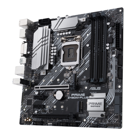
Какая ширина Asus Prime Z490M-PLUS?
Asus Prime Z490M-PLUS имеет ширину 244 mm.
Какая толщина Asus Prime Z490M-PLUS?
Asus Prime Z490M-PLUS имеет толщину 244 mm.
Инструкция Asus Prime Z490M-PLUS доступно в русский?
К сожалению, у нас нет руководства для Asus Prime Z490M-PLUS, доступного в русский. Это руководство доступно в английский.
Не нашли свой вопрос? Задайте свой вопрос здесь
|
|
Related Devices:
|
Types of Manuals:
The main types of Asus PRIME Z490M-PLUS instructions:
- User guide — rules of useing and characteristics
- Service manual — repair, diagnostics, maintenance
- Operation manual — description of the main functions of equipment
Motherboard Instructions by Asus:
-
Gigabyte 6GXU
6GXU1TABLE OF CONTENTS1. INTRODUCTION1.1. PREFACE……………………………………………………………………………………………… 1-11.2. KEY FEATURES ……………………………………………………………………………………. 1-11.3. PERFORMANCE LIST………………. …
6GXU Motherboard, 30
-
ASROCK IMB-1215
11 : M.2 Socket (Key-M) (M2_2)12 : M.2 Socket (Key-M) (M2_1)13 : eDP Connector 5 : Chassis FAN Connector (+12V) 6 : Chassis Intrusion Headers CI1 : Close: Active Case Open Open: Normal Cl2 : Close: Normal Open: Active Case Open7 : SATA3 Connectors (SATA3_1, SATA3_2)8 : M.2 Socket (Ke …
IMB-1215 Motherboard, 2
-
AMD 849BS
849BS USER’S MANUAL M/B For Socket-A Athlon/Duron Processor NO. G03-849BSR1A Release date: April 2001 ** Year 2000 compliant ** Trademark: * Specifications and Information contained in this documentation are furnished for information use only, and are subject to change at any time without …
849BS Motherboard, 52
-
Texas Instruments ISO1644DWEVM
User’s GuideISO1644DWEVM Reinforced Isolated I2C With GPIOsEvaluation ModuleABSTRACTThis user’s guide describes the evaluation module (EVM) for TI’s ISO1642, ISO1643, and ISO1644 isolatedI2C transceivers with general purpose input/output (GPIO) channels. This EVM helps designers evaluateperformance of these is …
ISO1644DWEVM Motherboard, 12
-
MSI MAG B460M BAZOOKA
IQuick StartQuick StartThank you for purchasing the MSI® MAG B460M BAZOOKA motherboard. This Quick Start section provides demonstration diagrams about how to install your computer. Some of the installations also provide video demonstrations. Please link to the URL to watch it with the web browser on your phone or tabl …
MAG B460M BAZOOKA Motherboard, 174
-
SOYO SY-6ILA
SY-6ILAMotherboard****************************************************Socket 370 for Intel CeleronTM ProcessorIntel 440 LX AGP/PCI Motherboard66MHz Front Side Bus supportedATX Form Factor****************************************************User’s Guide&Technical Reference …
SY-6ILA Motherboard, 73
![]()
PRIME Z490M-PLUS
Motherboard


E16187
First Edition
February 2020
Copyright © 2020 ASUSTeK COMPUTER INC. All Rights Reserved.
No part of this manual, including the products and software described in it, may be reproduced, transmitted, transcribed, stored in a retrieval system, or translated into any language in any form or by any means, except documentation kept by the purchaser for backup purposes, without the express written permission of ASUSTeK COMPUTER INC. (“ASUS”).
Product warranty or service will not be extended if: (1) the product is repaired, modified or altered, unless such repair, modification of alteration is authorized in writing by ASUS; or (2) the serial number of the product is defaced or missing.
ASUS PROVIDES THIS MANUAL “AS IS” WITHOUT WARRANTY OF ANY KIND, EITHER EXPRESS OR IMPLIED, INCLUDING BUT NOT LIMITED TO THE IMPLIED WARRANTIES OR CONDITIONS OF MERCHANTABILITY OR FITNESS FOR A PARTICULAR PURPOSE. IN NO EVENT SHALL ASUS, ITS DIRECTORS, OFFICERS, EMPLOYEES OR AGENTS BE LIABLE FOR ANY INDIRECT, SPECIAL, INCIDENTAL, OR CONSEQUENTIAL DAMAGES (INCLUDING DAMAGES FOR LOSS OF PROFITS, LOSS OF BUSINESS, LOSS OF USE OR DATA, INTERRUPTION OF BUSINESS AND THE LIKE), EVEN IF ASUS HAS BEEN ADVISED OF THE POSSIBILITY OF SUCH DAMAGES ARISING FROM ANY DEFECT OR ERROR IN THIS MANUAL OR PRODUCT.
SPECIFICATIONS AND INFORMATION CONTAINED IN THIS MANUAL ARE FURNISHED FOR INFORMATIONAL USE ONLY, AND ARE SUBJECT TO CHANGE AT ANY TIME WITHOUT NOTICE, AND SHOULD NOT BE CONSTRUED AS A COMMITMENT BY ASUS. ASUS ASSUMES NO RESPONSIBILITY OR LIABILITY FOR ANY ERRORS OR INACCURACIES THAT MAY APPEAR IN THIS MANUAL, INCLUDING THE PRODUCTS AND SOFTWARE DESCRIBED IN IT.
Products and corporate names appearing in this manual may or may not be registered trademarks or copyrights of their respective companies, and are used only for identification or explanation and to the owners’ benefit, without intent to infringe.
Offer to Provide Source Code of Certain Software
This product contains copyrighted software that is licensed under the General Public License (“GPL”), under the Lesser General Public License Version (“LGPL”) and/or other Free Open Source Software Licenses. Such software in this product is distributed without any warranty to the extent permitted by the applicable law. Copies of these licenses are included in this product.
Where the applicable license entitles you to the source code of such software and/or other additional data, you may obtain it for a period of three years after our last shipment of the product, either
(1)for free by downloading it from https://www.asus.com/support/
or
(2)for the cost of reproduction and shipment, which is dependent on the preferred carrier and the location where you want to have it shipped to, by sending a request to:
ASUSTeK Computer Inc.
Legal Compliance Dept.
15 Li Te Rd.,
Beitou, Taipei 112
Taiwan
In your request please provide the name, model number and version, as stated in the About Box of the product for which you wish to obtain the corresponding source code and your contact details so that we can coordinate the terms and cost of shipment with you.
The source code will be distributed WITHOUT ANY WARRANTY and licensed under the same license as the corresponding binary/object code.
This offer is valid to anyone in receipt of this information.
ASUSTeK is eager to duly provide complete source code as required under various Free Open Source Software licenses. If however you encounter any problems in obtaining the full corresponding source code we would be much obliged if you give us a notification to the email address gpl@asus.com, stating the product and describing the problem (please DO NOT send large attachments such as source code archives, etc. to this email address).
ii

Contents
|
Safety information………………………………………………………………………………………… |
iv |
|
About this guide…………………………………………………………………………………………….. |
v |
|
PRIME Z490M-PLUS specifications summary…………………………………………………. |
vi |
|
Connectors with shared bandwidth……………………………………………………………….. |
ix |
|
Package contents………………………………………………………………………………………….. |
x |
|
Installation tools and components…………………………………………………………………. |
xi |
|
Chapter 1: |
Product Introduction |
||
|
1.1 |
Before you proceed………………………………………………………………………… |
1-1 |
|
|
1.2 |
Motherboard layout………………………………………………………………………… |
1-2 |
|
|
Chapter 2: |
Basic Installation |
||
|
2.1 |
Building your PC system………………………………………………………………… |
2-1 |
|
|
2.1.1 |
CPU installation………………………………………………………………… |
2-1 |
|
|
2.1.2 |
Cooling system installation…………………………………………………. |
2-3 |
|
|
2.1.3 |
DIMM installation………………………………………………………………. |
2-5 |
|
|
2.1.4 |
M.2 installation………………………………………………………………….. |
2-6 |
|
|
2.1.5 |
Motherboard installation…………………………………………………….. |
2-7 |
|
|
2.1.6 |
ATX power connection……………………………………………………….. |
2-9 |
|
|
2.1.7 |
SATA device connection…………………………………………………… |
2-10 |
|
|
2.1.8 |
Front I/O connector………………………………………………………….. |
2-11 |
|
|
2.1.9 |
Expansion card installation……………………………………………….. |
2-12 |
|
|
2.2 |
Motherboard rear and audio connections………………………………………. |
2-13 |
|
|
2.2.1 |
Rear I/O connection…………………………………………………………. |
2-13 |
|
|
2.2.2 |
Audio I/O connections………………………………………………………. |
2-14 |
|
|
2.3 |
Starting up for the first time………………………………………………………….. |
2-17 |
|
|
2.4 |
Turning off the computer………………………………………………………………. |
2-17 |
|
|
Chapter 3: |
BIOS and RAID Support |
||
|
3.1 |
Knowing BIOS………………………………………………………………………………… |
3-1 |
|
|
3.2 |
BIOS setup program……………………………………………………………………….. |
3-2 |
|
|
3.3 |
ASUS EZ Flash 3…………………………………………………………………………….. |
3-3 |
|
|
3.4 |
ASUS CrashFree BIOS 3…………………………………………………………………. |
3-4 |
|
|
3.5 |
RAID configurations……………………………………………………………………….. |
3-5 |
|
|
Appendix |
|||
|
Notices |
……………………………………………………………………………………………………… |
A-1 |
|
|
ASUS contact information………………………………………………………………………….. |
A-6 |
iii

Safety information
Electrical safety
•To prevent electrical shock hazard, disconnect the power cable from the electrical outlet before relocating the system.
•When adding or removing devices to or from the system, ensure that the power cables for the devices are unplugged before the signal cables are connected. If possible, disconnect all power cables from the existing system before you add a device.
•Before connecting or removing signal cables from the motherboard, ensure that all power cables are unplugged.
•Seek professional assistance before using an adapter or extension cord. These devices could interrupt the grounding circuit.
•Ensure that your power supply is set to the correct voltage in your area. If you are not sure about the voltage of the electrical outlet you are using, contact your local power company.
•If the power supply is broken, do not try to fix it by yourself. Contact a qualified service technician or your retailer.
Operation safety
•Before installing the motherboard and adding devices on it, carefully read all the manuals that came with the package.
•Before using the product, ensure all cables are correctly connected and the power cables are not damaged. If you detect any damage, contact your dealer immediately.
•To avoid short circuits, keep paper clips, screws, and staples away from connectors, slots, sockets and circuitry.
•Avoid dust, humidity, and temperature extremes. Do not place the product in any area where it may become wet.
•Place the product on a stable surface.
•If you encounter technical problems with the product, contact a qualified service technician or your retailer.
•Your motherboard should only be used in environments with ambient temperatures between 0°C and 40°C.
iv

About this guide
This user guide contains the information you need when installing and configuring the motherboard.
How this guide is organized
This guide contains the following parts:
•Chapter 1: Product Introduction
This chapter describes the features of the motherboard and the new technology it supports. It includes description of the switches, jumpers, and connectors on the motherboard.
•Chapter 2: Basic Installation
This chapter lists the hardware setup procedures that you have to perform when installing system components.
•Chapter 3: BIOS and RAID Support
This chapter tells how to boot into the BIOS, upgrade BIOS using the EZ Flash Utility and support on RAID.
Where to find more information
Refer to the following sources for additional information and for product and software updates.
1.ASUS website
The ASUS website (www.asus.com) provides updated information on ASUS hardware and software products.
2.Optional documentation
Your product package may include optional documentation, such as warranty flyers, that may have been added by your dealer. These documents are not part of the standard package.
Conventions used in this guide
To ensure that you perform certain tasks properly, take note of the following symbols used throughout this manual.
CAUTION: Information to prevent damage to the components and injuries to yourself when trying to complete a task.
IMPORTANT: Instructions that you MUST follow to complete a task.
NOTE: Tips and additional information to help you complete a task.
v

PRIME Z490M-PLUS specifications summary
|
Intel® Socket LGA1200 for 10th Gen Intel® Core™, Pentium® Gold and |
||
|
Celeron® processors* |
||
|
Supports Intel® 14 nm CPU |
||
|
CPU |
Supports Intel® Turbo Boost Technology 2.0 and Intel® Turbo Boost Max |
|
|
Technology 3.0** |
||
|
* Refer to www.asus.com for CPU support list. |
||
|
** Intel® Turbo Boost Max Technology 3.0 support depends on the CPU types. |
||
|
Chipset |
Intel® Z490 Chipset |
|
|
4 x DIMM, Max. 128GB, DDR4 4400(O.C.) / 4266(O.C.) / 4133(O.C.) |
||
|
/ 4000(O.C.) / 3866(O.C.) / 3733(O.C.) / 3600(O.C.) / 3466(O.C.) / |
||
|
3400(O.C.) / 3333(O.C.) / 3300(O.C.) / 3200(O.C.) / 3000(O.C.) / |
||
|
2933(O.C.) /2800(O.C.) / 2666 / 2400 / 2133 MHz Non-ECC, Un-buffered |
||
|
Memory* |
||
|
Memory |
Dual Channel Memory Architecture |
|
|
Supports Intel® Extreme Memory Profile (XMP) |
||
|
OptiMem |
||
|
* 10th Gen Intel® Core™ i9/i7 CPUs support 2933/2800/2666/2400/2133 natively. |
||
|
Refer to www.asus.com for the Memory QVL (Qualified Vendors Lists). |
||
|
1 x DisplayPort 1.4** |
||
|
1 x HDMITM 1.4b |
||
|
Graphics |
1 x DVI-D |
|
|
* Graphics specifications may vary between CPU types. |
||
|
** Support DisplayPort 1.4 with max. resolution of 4096 x 2304 @60Hz. Please |
||
|
refer to www.intel.com for any update. |
||
|
Intel® 10th Gen Processors* |
||
|
1 x PCIe 3.0 x16 slot (supports x16 mode) |
||
|
Expansion Slots |
Intel® Z490 Chipset |
|
|
1 x PCIe 3.0 x16 slot (supports x4 mode) |
||
|
2 x PCIe 3.0 x1 slots |
||
|
* Support PCIe bifurcation for RAID on CPU function. |
||
|
Multi-GPU Support |
Supports AMD 2-Way CrossFireX™ Technology |
|
|
Total supports 2 x M.2 slots and 5 x SATA 6Gb/s ports |
||
|
Intel® Z490 Chipset |
||
|
M.2_1 slot (Key M), type 2242/2260/2280/22110 |
||
|
(supports PCIe 3.0 x4 mode) |
||
|
M.2_2 slot (Key M), type 2242/2260/2280 |
||
|
Storage |
(supports PCIe 3.0 x4 & SATA mode)* |
|
|
5 x SATA 6Gb/s ports |
||
|
Intel® Rapid Storage Technology supports Raid 0,1,5,10 |
||
|
Intel® Optane™ Memory Ready |
||
|
* When a device in SATA mode is installed on the M.2_2 socket, SATA6G_1 |
||
|
port cannot be used. |
||
|
Ethernet |
1 x Intel® I219V 1Gb Ethernet |
|
|
(continued on the next page) |
vi

PRIME Z490M-PLUS specifications summary
|
Rear USB (Total 6 ports) |
||
|
2 x USB 3.2 |
Gen 2 ports (1 x Type-A + 1 x USB Type-C®) |
|
|
2 x USB 3.2 |
Gen 1 ports (2 x Type-A) |
|
|
USB |
2 x USB 2.0 ports (2 x Type-A) |
Front USB (Total 8 ports)
2 x USB 3.2 Gen 1 headers support additional 4 USB 3.2 Gen 1 ports 2 x USB 2.0 headers support additional 4 USB 2.0 ports
|
Realtek ALC887 8-Channel High Definition Audio CODEC* |
|||
|
— Jack-detection, Multi-streaming, Front Panel Jack-retasking |
|||
|
— Supports up to 24-Bit/192kHz playback |
|||
|
Audio Features: |
|||
|
— LED-illuminated audio trace path design |
|||
|
Audio |
— Premium Japanese audio capacitors |
||
|
— Audio Shielding |
|||
|
— Dedicated audio PCB layers |
|||
|
* A chassis with an HD audio module in the front panel is required to support |
|||
|
8-channel audio output. |
|||
|
** Due to limitations in HDA bandwidth, 32-Bit/192kHz is not supported for |
|||
|
8-Channel audio. |
|||
|
2 x USB 3.2 Gen 2 ports (1 x Type-A + 1 x USB Type-C®) |
|||
|
2 x USB 3.2 Gen 1 ports (2 x Type-A) |
|||
|
2 x USB 2.0 ports (2 x Type-A) |
|||
|
1 x DisplayPort |
|||
|
Back I/O Ports |
1 x DVI-D port |
||
|
1 x HDMITM port |
|||
|
1 x Intel® I219V 1Gb Ethernet port |
|||
|
3 x Audio jacks |
|||
|
1 x PS/2 Keyboard/Mouse combo port |
|||
|
Fan and cooling-related |
|||
|
1 x 4-pin CPU Fan header |
|||
|
1 x 4-pin AIO_Pump header |
|||
|
3 x 4-pin Chassis Fan headers |
|||
|
Power related |
|||
|
1 x 24-pin Main Power connector |
|||
|
Internal I/O Connectors |
1 x 8-pin +12V Power connector |
||
|
1 x 4-pin +12V Power connector |
|||
|
Storage related |
|||
|
2 x M.2 slots (Key M) |
|||
|
5 x SATA 6Gb/s ports |
|||
|
USB |
|||
|
2 x USB 3.2 Gen 1 headers support additional 4 USB 3.2 Gen 1 ports |
|||
|
2 x USB 2.0 headers support additional 4 USB 2.0 ports |
|||
|
(continued on the next page) |
vii

PRIME Z490M-PLUS specifications summary
|
Miscellaneous |
||
|
1 x RGB header |
||
|
1 x Clear CMOS header |
||
|
Internal I/O Connectors |
1 x COM Port header |
|
|
1 x Front Panel Audio header (AAFP) |
||
|
1 x S/PDIF Out header |
||
|
1 x 20-3 pin System Panel header with Chassis intrude function |
||
|
1 x SPI TPM header (14-1pin) |
ASUS 5X PROTECTION III
— ASUS DIGI+ VRM (- Digital power design with Dr. MOS) — ASUS LANGuards
— ASUS Overvoltage Protection — ASUS SafeSlot Core+
— ASUS Stainless-Steel Back I/O
|
Special Features |
ASUS Q-Design |
|
|
— Q-DIMM |
||
|
— Q-Slot |
||
|
ASUS Thermal Solution |
||
|
— Aluminum heatsink design |
||
|
ASUS EZ DIY |
||
|
— Procool |
||
|
ASUS Exclusive Software Features |
||
|
Armoury Crate |
||
|
AI Suite 3 |
||
|
— Performance And Power Saving Utility |
||
|
EPU |
||
|
Digi+ VRM |
||
|
Fan Xpert 4 |
||
|
Software Features |
— EZ update |
|
|
AI Charger |
||
|
WinRAR |
||
|
UEFI BIOS |
||
|
ASUS EZ DIY |
||
|
— ASUS CrashFree BIOS 3 |
||
|
— ASUS EZ Flash 3 |
||
|
— ASUS UEFI BIOS EZ Mode |
||
|
BIOS |
128 Mb Flash ROM, UEFI AMI BIOS |
|
|
Manageability |
WOL by PME, PXE |
|
|
Operating System |
Windows® 10 — 64 bit |
|
|
Form Factor |
mATX Form Factor |
|
|
9.6 inch x 9.6 inch (24.4 cm x 24.4 cm) |
||
Specifications are subject to change without notice. Please refer to the ASUS website for the latest specifications.
viii

Connectors with shared bandwidth
24.4cm(9.6in)
KBMS_USB910
EATX12V_1
CHA_FAN2 EATX12V_2
ASM 1442K
HDMI_DP
LAN_U32G1_34
|
Intel® |
||||
|
I219V |
||||
|
AUDIO |
22110 |
2280 |
2260 |
2242 |
PCIEX16_1
LGA1200
|
CPU_FAN |
||||||||
|
DIGI+ |
||||||||
|
VRM |
||||||||
|
AIO_PUMP |
||||||||
|
DDR4 DIMM B1 (64bit, 288-pin module) |
DDR4 DIMM B2* (64bit, 288-pin module) |
DDR4 DIMM A1 (64bit, 288-pin module) |
DDR4 DIMM A2* (64bit, 288-pin module) |
EATXPWR U32G1 78 |
24.4cm(9.6in) |
|||
|
1(SOCKET3) |
M.2_1(SOCKET3) |
U32G1 56 |
||||||
|
_ |
||||||||
|
M.2 |
X4 |
X |
V |
|||||
|
PCIE |
SATA |
IRST |
|
PCIEX1_1 |
BATTERY |
||||
|
Super |
PCIE SATA |
IRST |
12 |
||
|
2(SOCKET3)M.2 |
X4 V |
V |
SATA6G34SATA6G |
||
|
COM_DEBUG |
|||||
|
I/O |
M.2_2(SOCKET3) |
Intel® |
|||
|
PCIEX1_2 |
Z490 |
||||
|
2280 |
2260 |
2242 |
|
ALC |
PCIEX16_2 |
128Mb |
|
887 |
BIOS |
|
|
CLRTC |
|
AAFP |
COM |
SPDIF_OUT |
CHA_FAN3 |
USB1112 |
USB1314 |
CHA_FAN1 |
SATA6G_5 |
TPM |
||||||||||
A
|
Configuration |
1 |
2 |
||
|
A |
M.2_2 |
SATA |
x4 |
|
|
SATA6G_1 |
— |
V |
||
A
When a device in SATA mode is installed on the M.2_2 socket, SATA6G_1 port cannot be used.
ix

Package contents
Check your motherboard package for the following items.
|
Motherboard |
1 x PRIME Z490M-PLUS motherboard |
|
|
Cables |
2 x SATA 6Gb/s cables |
|
|
Miscellaneous |
1 x I/O Shield |
|
|
1 x M.2 SSD screw package |
||
|
Installation Media |
1 x Support DVD |
|
|
Documentation |
1 x User manual |
|
If any of the above items is damaged or missing, contact your retailer.
x

Installation tools and components
Phillips (cross) screwdriver
|
PC chassis |
Power supply unit |
|
Intel® LGA 1200 CPU |
Intel® LGA 1200 compatible CPU Fan |
|
DDR4 DIMM |
SATA hard disk drive |
|
SATA optical disc drive (optional) |
Graphics card (optional) |
|
M.2 SSD module (optional) |
1 Bag of screws |
The tools and components in the table above are not included in the motherboard package.
xi

xii

1.1Before you proceed
Take note of the following precautions before you install motherboard components or change any motherboard settings.
•Unplug the power cord from the wall socket before touching any component.
•Before handling components, use a grounded wrist strap or touch a safely grounded object or a metal object, such as the power supply case, to avoid damaging them due to static electricity.
•Hold components by the edges to avoid touching the ICs on them.
•Whenever you uninstall any component, place it on a grounded antistatic pad or in the bag that came with the component.
•Before you install or remove any component, ensure that the ATX power supply is switched off or the power cord is detached from the power supply. Failure to do so may cause severe damage to the motherboard, peripherals, or components.
Chapter 1

1 Chapter
1.2Motherboard layout
|
4 |
5 |
|
KBMS_USB910 |
|
|
EATX12V_1 |
CHA_FAN2 EATX12V_2
ASM 1442K
HDMI_DP
LAN_U32G1_34
|
Intel® |
||||
|
I219V |
||||
|
AUDIO |
22110 |
2280 |
2260 |
2242 |
PCIEX16_1
|
1 |
4 |
2 |
|||||
|
24.4cm(9.6in) |
|||||||
|
CPU_FAN |
|||||||
|
DIGI+ |
|||||||
|
VRM |
|||||||
|
AIO_PUMP |
|||||||
|
LGA1200 |
(64bit,B1 288-pin module) |
(64bit,B2* 288-pin module) |
(64bit,A1 288-pin module) |
(64bit,A2* 288-pin module) |
EATXPWR |
||
|
DDR4 DIMM_ |
DDR4 DIMM_ |
DDR4 DIMM_ |
DDR4 DIMM_ |
U32G1 78 |
|||
|
1(SOCKET3) |
M.2_1(SOCKET3) |
U32G1 56 |
|||||
|
_ |
|||||||
|
M.2 |
X4 |
X |
V |
||||
|
PCIE |
SATA |
IRST |
|
3 |
PCIEX1_1 |
BATTERY |
||||
|
12 |
||||||
|
Super |
PCIE SATA |
IRST |
||||
|
2(SOCKET3)M.2 |
X4 V |
V |
SATA6G34SATA6G |
|||
|
COM_DEBUG |
||||||
|
I/O |
M.2_2(SOCKET3) |
Intel® |
||||
|
PCIEX1_2 |
Z490 |
|||||
|
2280 |
2260 |
2242 |
|
ALC |
PCIEX16_2 |
128Mb |
|
887 |
BIOS |
|
|
CLRTC |
|
AAFP |
COM |
SPDIF_OUT |
CHA_FAN3 |
USB1112 |
USB1314 |
CHA_FAN1 |
SATA6G_5 |
TPM |
|
13 |
12 |
14 |
10 |
4 |
9 |
11 |
4 |
7 |
16 |
5
24.4cm(9.6in)
8
6
 7
7
15
|
1-2 |
Chapter 1: Product Introduction |

Layout contents
1.CPU socket
2.DIMM slots
3.Expansion slots
4.Fan and Pump headers
5.Power connectors
6.M.2 slots (SOCKET 3)
7.SATA 6Gb/s ports
8.USB 3.2 Gen 1 headers
9.USB 2.0 headers
10.RGB headers
11.Clear CMOS header
12.COM Port header
13.Front Panel Audio header
14.S/PDIF Out header
15.SPI TPM header (14-1pin)
16.System Panel header
Page
1-4
1-5
1-7
1-9
1-10
1-11
1-12
1-13
1-14
1-15
1-16
1-17
1-17
1-18
1-18
1-19
Chapter 1

1 Chapter
1.CPU socket
The motherboard comes with a LGA1200 socket designed for 10th Gen Intel® CoreTM, Pentium® Gold and Celeron® Processors.
LGA1200
Ensure that you install the correct CPU designed for LGA1200 socket only. DO NOT install a CPU designed for other sockets on the LGA1200 socket.
The CPU fits in only one correct orientation. DO NOT force the CPU into the socket to prevent bending the connectors on the socket and damaging the CPU.
Ensure that all power cables are unplugged before installing the CPU.
Upon purchase of the motherboard, ensure that the PnP cap is on the socket and the socket contacts are not bent. Contact your retailer immediately if the PnP cap is missing, or if you see any damage to the PnP cap/socket contacts/motherboard components. ASUS will shoulder the cost of repair only if the damage is shipment/ transit-related.
Keep the cap after installing the motherboard. ASUS will process Return Merchandise Authorization (RMA) requests only if the motherboard comes with the cap on the LGA1200 socket.
The product warranty does not cover damage to the socket contacts resulting from incorrect CPU installation/removal, or misplacement/loss/incorrect removal of the PnP cap.
|
1-4 |
Chapter 1: Product Introduction |

2.DIMM slots
This motherboard comes with four Double Data Rate 4 (DDR4) Dual Inline Memory Module (DIMM) sockets.
A DDR4 memory module is notched differently from a DDR, DDR2, or DDR3 module. DO NOT install a DDR, DDR2, or DDR3 memory module to the DDR4 slot.
|
DIMM B1 DIMM B2* |
DIMM A1 DIMM A2* |
||||||||||||||||||||||||||||||||||||||||||||||||||||||||||||||
Recommended memory configurations
Chapter 1
|
DIMM_B1 |
|||
|
DIMM_B2* |
DIMM_B2* |
||
|
DIMM_A2* |
DIMM_A2* |
DIMM_A1 |
|
|
DIMM_A2* |
|||

1 Chapter
Memory configurations
You may install 2 GB, 4 GB, 8 GB, 16 GB, and 32 GB unbuffered and non ECC DDR4 DIMMs into the DIMM sockets.
You may install varying memory sizes in Channel A and Channel B. The system maps the total size of the lower-sized channel for the dual-channel configuration. Any excess memory from the higher-sized channel is then mapped for single-channel operation.
• The default memory operation frequency is dependent on its Serial Presence Detect (SPD), which is the standard way of accessing information from a memory module. Under the default state, some memory modules for overclocking may operate at a lower frequency than the vendor-marked value.
•For system stability, use a more efficient memory cooling system to support a full memory load or overclocking condition.
•Always install the DIMMS with the same CAS Latency. For an optimum compatibility, we recommend that you install memory modules of the same version or data code (D/C) from the same vendor. Check with the vendor to get the correct memory modules.
•Visit the ASUS website for the latest QVL.
|
1-6 |
Chapter 1: Product Introduction |

3.Expansion slots
Unplug the power cord before adding or removing expansion cards. Failure to do so may cause you physical injury and damage motherboard components.
Chapter 1
PCIEX16_1
 PCIEX1_1
 PCIEX1_2
PCIEX16_2
Recommended VGA configuration
|
Slot Description |
Single VGA |
Dual VGA |
||
|
PCIe 3.0 x16_1 |
x16 |
x16 |
||
|
PCIe 3.0 x16_2 |
— |
x4 |
||
• We recommend that you provide sufficient power when running CrossFireX™ mode.
•Ensure to connect the 8-pin and 4-pin power plugs when running CrossFireX™ mode.
•Connect a chassis fan to the chassis fan connectors when using multiple graphics cards for better thermal environment.
 Loading…
-
Драйверы
19
-
Инструкции по эксплуатации
2
Языки:

ASUS PRIME Z490M-PLUS инструкция по эксплуатации
(64 страницы)
- Языки:Японский
-
Тип:
PDF -
Размер:
4.4 MB -
Описание:
PRIME Z490M-PLUS User’s Manual ( Japanese Edition )
Просмотр

ASUS PRIME Z490M-PLUS инструкция по эксплуатации
(62 страницы)
- Языки:Немецкий
-
Тип:
PDF -
Размер:
3.98 MB -
Описание:
PRIME Z490M-PLUS User’s Manual ( German Edition )
Просмотр
На NoDevice можно скачать инструкцию по эксплуатации для ASUS PRIME Z490M-PLUS. Руководство пользователя необходимо для ознакомления с правилами установки и эксплуатации ASUS PRIME Z490M-PLUS. Инструкции по использованию помогут правильно настроить ASUS PRIME Z490M-PLUS, исправить ошибки и выявить неполадки.