-
Contents
-
Table of Contents
-
Bookmarks
Quick Links
Related Manuals for Asus ROG STRIX Z370-E GAMING
Summary of Contents for Asus ROG STRIX Z370-E GAMING
-
Page 1
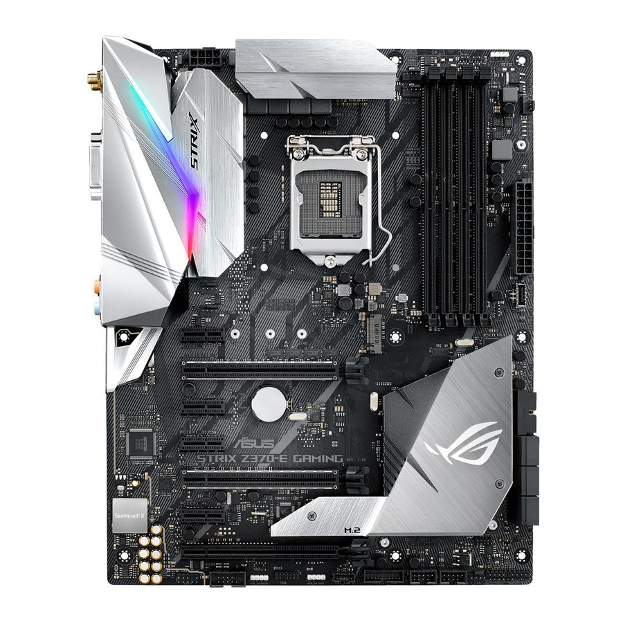
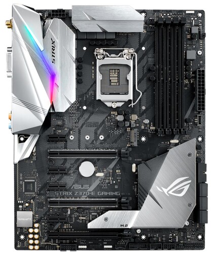
STRIX Z370-E GAMING… -
Page 2
Product warranty or service will not be extended if: (1) the product is repaired, modified or altered, unless such repair, modification of alteration is authorized in writing by ASUS; or (2) the serial number of the product is defaced or missing. -
Page 3: Table Of Contents
Contents Safety information …………………. vi About this guide ………………….vii ROG STRIX Z370-E GAMING specifications summary ……….. ix Package contents ………………… xiii Installation tools and components …………….. xiv Chapter 1: Product Introduction Motherboard overview …………….1-1 1.1.1 Before you proceed …………..1-1 1.1.2…
-
Page 4
3.6.11 USB Configuration …………..3-19 Monitor menu ………………. 3-20 Boot menu ………………..3-20 Tool menu ………………..3-22 3.9.1 ASUS EZ Flash 3 Utility …………3-22 3.9.2 Secure Erase …………….3-22 3.9.3 ASUS Overclocking Profile …………3-24 3.9.4 ASUS SPD Information …………. 3-24 3.9.5… -
Page 5
Rapid Storage Technology in UEFI BIOS ……4-2 ® 4.1.4 Intel Rapid Storage Technology Option ROM utility ….4-6 ® Creating a RAID driver disk…………..4-10 4.2.1 Creating a RAID driver disk in Windows ……… 4-10 ® Appendix Notices ……………………A-1 ASUS contact information ………………A-7… -
Page 6: Safety Information
Safety information Electrical safety • To prevent electrical shock hazard, disconnect the power cable from the electrical outlet before relocating the system. • When adding or removing devices to or from the system, ensure that the power cables for the devices are unplugged before the signal cables are connected. If possible, disconnect all power cables from the existing system before you add a device.
-
Page 7: About This Guide
Refer to the following sources for additional information and for product and software updates. ASUS website The ASUS website (www.asus.com) provides updated information on ASUS hardware and software products. Optional documentation Your product package may include optional documentation, such as warranty flyers, that may have been added by your dealer.
-
Page 8: Conventions Used In This Guide
Conventions used in this guide To ensure that you perform certain tasks properly, take note of the following symbols used throughout this manual. DANGER/WARNING: Information to prevent injury to yourself when trying to complete a task. CAUTION: Information to prevent damage to the components when trying to complete a task.
-
Page 9: Rog Strix Z370-E Gaming Specifications Summary
Supports AMD 3-Way CrossFireX™ Technology ® 1 x ASUS Wi-Fi module (Wi-Fi 802.11 a/b/g/n/ac and Bluetooth v4.2) 2 x USB3.1 Gen2 ports (1 x Type-A [red] and 1 x Type-C ports at back panel) 1 x DVI port 1 x HDMI port…
-
Page 10
Processors. Before using Intel Optane memory modules, ensure that you have ® updated your motherboard drivers and BIOS to the latest version from ASUS support website. ROG SupremeFX S1220A 8-Channel High Definition Audio CODEC — Supports up to 32-Bit/192kHz playback*… -
Page 11
ROG STRIX Z370-E GAMING specifications summary Intel I219-V Gigabit LAN- Dual interconnect between the integrated Media ® Access Controller (MAC) and physical layer (PHY) Anti-surge LANGuard ROG GameFirst Technology Wi-Fi 802.11 a/b/g/n/ac supports dual frequency band 2.4/5 GHz with Wireless &… -
Page 12
EZ Update Anti-virus software (OEM version) Operating Windows 10 64-bit ® system support Form factor ATX Form Factor, 12”x 9.6” (30.5cm x 24.4cm) Specifications are subject to change without notice. Please refer to the ASUS website for the latest specifications. -
Page 13: Package Contents
1 x RGB LED extension cable 1 x Addressable LED extension cable 1 x Thermal sensor cable 1 x I/O shield 1 x ASUS 2T2R dual band Wi-Fi moving antennas (Wi-Fi 802.11a/b/g/n/ac compliant) 1 x CPU Installation tool 1 x ROG cable label…
-
Page 14: Installation Tools And Components
Installation tools and components Intel 1151 CPU ® Intel 1151 compatible CPU Fan ® Phillips (cross) screwdriver SATA hard disk drive PC chassis 1 bag of screws DIMM Power supply unit SATA optical disc drive (optional) Graphics card The tools and components listed above are not included in the motherboard package.
-
Page 15: Chapter 1: Product Introduction
Chapter 1: Product Introduction Product Introduction Motherboard overview 1.1.1 Before you proceed Take note of the following precautions before you install motherboard components or change any motherboard settings. • Unplug the power cord from the wall socket before touching any component. • Before handling components, use a grounded wrist strap or touch a safely grounded object or a metal object, such as the power supply case, to avoid damaging them due to static electricity. • Hold components by the edges to avoid touching the ICs on them. • Whenever you uninstall any component, place it on a grounded antistatic pad or in the bag that came with the component. • Before you install or remove any component, ensure that the ATX power supply is switched off or the power cord is detached from the power supply. Failure to do so may cause severe damage to the motherboard, peripherals, or components. ASUS ROG STRIX Z370-E GAMING…
-
Page 16: Motherboard Layout
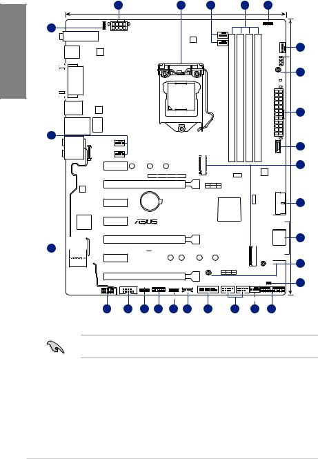
1.1.2 Motherboard layout 24.4cm(9.6in) CPU_OV RGB_HEADER2 CPU_FAN EATX12V M.2(WIFI) DIGI+ CHA_FAN1 CPU_OPT USB31G2_EC1 USB31G2_E2 3142 BOOT_DEVICE_LED VGA_LED DRAM_LED CPU_LED MOUNT PWR_LED LGA1151 HDMI USB1314 1442K LAN1_U31G1_56 CHA_FAN2 AUDIO AIO_PUMP PCIE_X1_1 2280 2260 2242 3142 ASM1480 ASM1480 ASM1480 ASM1480 ASM1480 M.2_2(SOCKET3) PCIE_X16/X8_1 PCIE SATA IRST…
-
Page 17: Layout Contents
9. USB 3.1 Gen1 connectors (20-1 pin U31G1_12,U31G1_34) 1-14 10. Intel Serial ATA 6 Gb/s connectors (7-pin SATA6G_12, SATA 6G_34, ® 1-12 SATA 6G_56) 11. Clear RTC RAM jumper (2-pin CLRTC) 12. System panel connector (20-3 pin PANEL) 1-17 13. USB 2.0 connectors (10-1 pin USB910, USB1112) 1-14 14. Addressable RGB header (4-1 pin ADD_HEADER) 1-21 15. TPM connector (14-1 pin TPM) 1-18 16. Serial port connector (10-1 pin COM) 1-18 17. Front panel audio connector (10-1 pin AAFP) 1-13 18. Thermal sensor cable connector (2-pin T_SENSOR) 1-19 19. CPU over voltage jumper (3-pin CPU_OV) 1-10 ASUS ROG STRIX Z370-E GAMING…
-
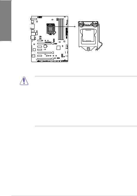
Page 18: Central Processing Unit (Cpu)
1.1.3 Central Processing Unit (CPU) The motherboard comes with a surface mount LGA1151 socket designed for the 8th Generation Intel Core™ processors. ® ® STRIX Z370-E GAMING ROG STRIX Z370-E GAMING CPU LGA1151 • Ensure that all power cables are unplugged before installing the CPU. • Upon purchase of the motherboard, ensure that the PnP cap is on the socket and the socket contacts are not bent. Contact your retailer immediately if the PnP cap is missing, or if you see any damage to the PnP cap/socket contacts/motherboard components. ASUS will shoulder the cost of repair only if the damage is shipment/ transit-related. • Keep the cap after installing the motherboard. ASUS will process Return Merchandise Authorization (RMA) requests only if the motherboard comes with the cap on the LGA1151 socket. • The product warranty does not cover damage to the socket contacts resulting from incorrect CPU installation/removal, or misplacement/loss/incorrect removal of the PnP cap. Chapter 1: Product Introduction…
-
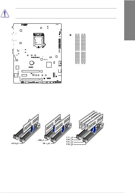
Page 19: System Memory
1.1.4 System memory The motherboard comes with four DDR4 (Double Data Rate 4) Quad Inline Memory Modules (DIMM) slots. A DDR4 module is notched differently from a DDR, DDR2, or DDR3 module. DO NOT install a DDR, DDR2, or DDR3 memory module to the DDR4 slot. ® STRIX Z370-E GAMING ROG STRIX Z370-E GAMING 288-pin DDR4 DIMM sockets Recommended memory configurations ASUS ROG STRIX Z370-E GAMING…
-
Page 20: Memory Configurations
OS when you want to install 4 GB or more on the ® motherboard. c) For more details, refer to the Microsoft support site at http://support.microsoft. ® com/kb/929605/en-us. • The design of the DIMM fan may vary. Ensure that the DIMM fan fits to the motherboard • The default memory operation frequency is dependent on its Serial Presence Detect (SPD), which is the standard way of accessing information from a memory module. Under the default state, some memory modules for overclocking may operate at a lower frequency than the vendor-marked value. • For system stability, use a more efficient memory cooling system to support a full memory load (4 DIMMs) or overclocking condition. • Memory modules with memory frequency higher than 2133MHz and their corresponding timing or the loaded XMP profile is not the JEDEC memory standard. The stability and compatibility of the memory modules depend on the CPU’s capabilities and other installed devices. • Always install the DIMMS with the same CAS Latency. For an optimum compatibility, we recommend that you install memory modules of the same version or data code (D/C) from the same vendor. Check with the vendor to get the correct memory modules. • ASUS exclusively provides hyper DIMM support function. • Hyper DIMM support is subject to the physical characteristics of individual CPUs. Load the X.M.P. or D.O.C.P. settings in the BIOS for the hyper DIMM support. • Visit the ASUS website for the latest QVL. Chapter 1: Product Introduction…
-
Page 21: Expansion Slots
1.1.5 Expansion slots Unplug the power cord before adding or removing expansion cards. Failure to do so may cause you physical injury and damage motherboard components. PCIE_X1_1 PCIE_X16/X8_1 PCIE_X1_2 PCIE_X1_3 ® STRIX Z370-E GAMING PCIE_X8_2 PCIE_X1_4 PCIE_X4 Slot No. Slot Description PCIE_x1_1 slot PCIE_x16/x8_1 slot PCIE_x1_2 slot PCIE_x1_3 slot PCIE_x8_2 slot PCIE_x1_4 slot PCIE_x4 slot ASUS ROG STRIX Z370-E GAMING…
-
Page 22
PCI Express 3.0 operating mode VGA configuration PCIe_x16/x8_1 PCIe_x8_2 x16 (single VGA Single VGA/PCIe card recommended) Dual VGA/PCIe cards • We recommend that you provide sufficient power when running CrossFireX™ or SLI™ mode. • Connect a chassis fan to the motherboard connector labeled CHA_FAN1-2 when using multiple graphics cards for better thermal environment. PCI Express 3.0 operating mode Hyper M.2 X16 card configuration PCIe_x16/x8_1 PCIe_x8_2 2 Intel SSDs on CPU ® x4+x4 support 3 Intel SSDs on CPU ® x8+x4+x4 support •… -
Page 23: Jumpers And Holes
1.1.6 Jumpers and holes Clear RTC RAM jumper (2-pin CLRTC) This jumper allows you to clear the Real Time Clock (RTC) RAM in CMOS. You can clear the CMOS memory of date, time, and system setup parameters by erasing the CMOS RTC RAM data. The onboard button cell battery powers the RAM data in CMOS, which include system setup information such as system passwords. CLRTC ® STRIX Z370-E GAMING PIN 1 ROG STRIX Z370-E GAMING Clear RTC RAM To erase the RTC RAM: Turn OFF the computer and unplug the power cord. Short-circuit pin 1-2 with a metal object or jumper cap for about 5-10 seconds. Plug the power cord and turn ON the computer. Hold down the <Delete> key during the boot process and enter BIOS setup to re-enter data. Except when clearing the RTC RAM, never remove the cap on CLRTC jumper default position. Removing the cap will cause system boot failure! • If the steps above do not help, remove the onboard battery and move the jumper again to clear the CMOS RTC RAM data. After the CMOS clearance, reinstall the battery.
-
Page 24
® STRIX Z370-E GAMING ROG STRIX Z370-E GAMING CPU_OV setting 3D Mount Secure 3D printed parts to these 3D Mount holes for a personalized motherboard. 3D Mount 3D Mount ® STRIX Z370-E GAMING 3D Mount ROG STRIX Z370-E GAMING 3D Printing Mount • Download 3D source files at http://www.asus.com. • Use the bundled 3D Mount screws to install the 3D printed parts. Chapter 1: Product Introduction 1-10… -
Page 25: Onboard Leds
BOOT (YELLOW GREEN) VGA (WHITE) DRAM (YELLOW) CPU (RED) ® STRIX Z370-E GAMING ROG STRIX Z370-E GAMING CPU/DRAM/BOOT_DEVICE/VGA LED Standby Power LED The motherboard comes with a standby power LED. The LED lights up to indicate that the system is ON, in sleep mode, or in soft-off mode. This is a reminder that you should shut down the system and unplug the power cable before removing or plugging in any motherboard component. The illustration below shows the location of the onboard LED. PWR_LED ® STRIX Z370-E GAMING ROG STRIX Z370-E GAMING PWR_LED ASUS ROG STRIX Z370-E GAMING 1-11…
-
Page 26: Internal Connectors
® RSATA_TXP5 RSATA_TXP6 STRIX Z370-E GAMING RSATA_TXN5 RSATA_TXN6 RSATA_RXN5 RSATA_RXN6 RSATA_RXP5 RSATA_RXP6 ROG STRIX Z370-E GAMING Intel SATA 6 Gb/s connectors ® • These connectors are set to [AHCI] by default. If you intend to create a Serial ATA RAID set using these connectors, set the SATA Mode item in the BIOS to [Intel RST Premium With Intel Optane System Acceleration (RAID)]. • Before creating a RAID set, refer to the manual bundled in the motherboard support DVD. Chapter 1: Product Introduction…
-
Page 27
USB 3.1 Gen2 front panel connector (U31G2_E3) This connector allows you to connect a USB 3.1 Gen2 module for additional USB 3.1 Gen2 ports. The latest USB 3.1 Gen2 connectivity provides data transfer speeds of up to 10 Gbps. The next-generation standard is completely backward-compatible with your existing USB devices. U31G2_E3 VBUS SBU2 TX2+ SBU1 TX2- VBUS RX2+ RX1- RX2- RX1+ TX1- TX1+ ® VBUS STRIX Z370-E GAMING ROG STRIX Z370-E GAMING USB 3.1 Gen 2 front panel connector ASUS ROG STRIX Z370-E GAMING 1-13… -
Page 28
Gen1 front or rear panel ports. With an installed USB 3.1 Gen1 module, you can enjoy all the benefits of USB 3.1 Gen1 including faster data transfer speeds of up to 5 Gb/s, faster charging time for USB-chargeable devices, optimized power efficiency, and backward compatibility with USB 2.0. U31G1_12 U31G1_34 PIN 1 PIN 1 ® STRIX Z370-E GAMING ROG STRIX Z370-E GAMING USB 3.1 Gen 1 connectors The USB 3.1 Gen1 module is purchased separately. USB 2.0 connectors (10-1 pin USB910, USB1112) These connectors are for USB 2.0 ports. Connect the USB module cable to these connectors, then install the module to a slot opening at the back of the system chassis. This USB connector complies with USB 2.0 specification that supports up to 480 Mb/s connection speed. USB910 USB1112 ® STRIX Z370-E GAMING… -
Page 29
• Ensure that the CPU fan cable is securely installed to the CPU fan connector. CPU_FAN CHA_FAN1 CPU_OPT CHA FAN PWM CHA FAN IN CHA FAN PWR CHA_FAN2 AIO_PUMP EXT_FAN M.2_FAN ® STRIX Z370-E GAMING ROG STRIX Z370-E GAMING Fan connectors • The CPU_FAN connector supports the CPU fan of maximum 1A (12 W) fan power. • The EXT_FAN connector supports 2 of 5 thermal sensor sources. • Connect the fan of your water cooling kit to the AIO_PUMP connector. ASUS ROG STRIX Z370-E GAMING 1-15… -
Page 30
-5 Volts PIN 1 +5 Volts +5 Volts PSON# +3 Volts -12 Volts +3 Volts +3 Volts PIN 1 ® STRIX Z370-E GAMING ROG STRIX Z370-E GAMING ATX power connectors • For a fully configured system, we recommend that you use a power supply unit (PSU) that complies with ATX 12 V Specification 2.0 (or later version) and provides a minimum power of 350 W. • DO NOT forget to connect the 8-pin EATX12V power plug. Otherwise, the system will not boot. • We recommend that you use a PSU with a higher power output when configuring a system with more power-consuming devices. The system may become unstable or may not boot up if the power is inadequate. -
Page 31: System Panel Connector
SPEAKER CHASSIS PANEL PIN 1 ® STRIX Z370-E GAMING HDD_LED RESET PLED ROG STRIX Z370-E GAMING System panel connector • System power LED (2-pin or 3-1 pin PLED) The 2-pin or 3-1 pin connector is for the system power LED. Connect the chassis power LED cable to this connector. The system power LED lights up when you turn on the system power, and blinks when the system is in sleep mode. • Hard disk drive activity LED (2-pin HDD_LED) This 2-pin connector is for the HDD Activity LED. Connect the HDD Activity LED cable to this connector. The HDD LED lights up or flashes when data is read from or written…
-
Page 32
PIN 1 ® STRIX Z370-E GAMING ROG STRIX Z370-E GAMING TPM connector The TPM module is purchased separately. Serial port connector (10-1 pin COM) This connector is for a serial (COM) port. Connect the serial port module cable to this connector, then install the module to a slot opening at the back of the system chassis. ® STRIX Z370-E GAMING PIN 1 ROG STRIX Z370-E GAMING Serial port connector The COM module is purchased separately. Chapter 1: Product Introduction 1-18… -
Page 33
M.2 sockets (M.2_1; M.2_2) These sockets allow you to install M.2 SSD modules. M.2_2(SOCKET3) 2280 2260 2242 M.2_1(SOCKET3) ® STRIX Z370-E GAMING 2280 2260 2242 ROG STRIX Z370-E GAMING M.2 sockets • M.2_1 socket supports PCIe 3.0 x4 and SATA mode M Key design and type 2242 / 2260 / 2280 PCIe and SATA storage devices. • M.2_2 socket supports PCIe 3.0 x4 M Key design and type 2242 / 2260 / 2280 PCIe storage devices. • These sockets support IRST (Intel Rapid Storage Technology). ® The M.2 SSD module is purchased separately. Thermal sensor connector (2-pin T_SENSOR) This connector is for the thermistor cable that monitors the temperature of the devices and the critical components inside the motherboard. Connect the thermistor cable… -
Page 34
RGB headers (4-pin RGB_HEADER1-2) These connectors are for RGB LED strips. RGB_HEADER2 PIN 1 +12V G R B RGB_HEADER1 PIN 1 +12V G R B ® STRIX Z370-E GAMING ROG STRIX Z370-E GAMING RGB_HEADER connectors The RGB header supports 5050 RGB multi-color LED strips (12V/G/R/B), with a maximum power rating of 2A (12V), and no longer than 2 m. Before you install or remove any component, ensure that the ATX power supply is switched off or the power cord is detached from the power supply. Failure to do so may cause severe damage to the motherboard, peripherals, or components. • Actual lighting and color will vary with LED strip. • If your LED strip does not light up, check if the RGB LED extension cable and the RGB LED strip is connected in the correct orientation, and the 12V connector is aligned with the 12V header on the motherboard. -
Page 35
Addressable RGB header (4-1 pin ADD_HEADER) This connector is for individually addressable RGB WS2812B LED strips with embedded WS2811LED driver ICs. ® STRIX Z370-E GAMING ROG STRIX Z370-E GAMING EXTREME ADD header The addressable RGB header supports WS2812B addressable RGB LED strips (5V/Data/ Ground), with a maximum power rating of 3A (5V) and a maximum of 60 LEDs. Before you install or remove any component, ensure that the ATX power supply is switched off or the power cord is detached from the power supply. Failure to do so may cause severe damage to the motherboard, peripherals, or components. • Actual lighting and color will vary with LED strip. • If your LED strip does not light up, check if the addressable RGB LED strip is connected in the correct orientation, and the 5V connector is aligned with the 5V header on the motherboard. • The addressable RGB LED strip will only light up under the operating system. • The addressable RGB LED strip is purchased separately. ASUS ROG STRIX Z370-E GAMING 1-21… -
Page 36
Chapter 1: Product Introduction 1-22… -
Page 37: Chapter 2: Basic Installation
2.1.1 Motherboard installation Install the ASUS Q-Shield to the chassis rear I/O panel. Place the motherboard into the chassis, ensuring that its rear I/O ports are aligned to the chassis’ rear I/O panel.
-
Page 38
Place nine (9) screws into the holes indicated by circles to secure the motherboard to the chassis. ® STRIX Z370-E GAMING DO NOT overtighten the screws! Doing so can damage the motherboard. Chapter 2: Basic Installation… -
Page 39: Cpu Installation
Ensure that you install the correct CPU designed for LGA1151 socket only. DO NOT install a CPU designed for LGA1155 and LGA1156 sockets on the LGA1151 socket. Top of CPU Bottom of CPU Bottom of CPU ASUS ROG STRIX Z370-E GAMING…
-
Page 40
Top of CPU • The CPU Installation Tool is only compatible on ASUS motherboards with a Intel ® LGA1151 socket. • Ensure that the CPU is firmly clicked into place before installing it onto the CPU socket on the motherboard. • Use the CPU Installation Tool for installing the CPU only. DO NOT damage or bend the CPU Installation Tool. • Always firmly hold both sides of the CPU Installation Tool when installing, removing, or picking up the CPU Installation Tool. • Ensure to use a soft stable surface when installing the CPU to the CPU Installation Tool to prevent CPU damage. • ASUS will not cover damages resulting from incorrect CPU installation/removal, incorrect CPU orientation/placement, or other damages resulting from negligence by the user. -
Page 41: Cpu Heatsink And Fan Assembly Installation
2.1.3 CPU heatsink and fan assembly installation Apply the Thermal Interface Material to the CPU heatsink and CPU before you install the heatsink and fan, if necessary. To install the CPU heatsink and fan assembly ASUS ROG STRIX Z370-E GAMING…
-
Page 42
To uninstall the CPU heatsink and fan assembly Chapter 2: Basic Installation… -
Page 43: Dimm Installation
2.1.4 DIMM installation To remove a DIMM ASUS ROG STRIX Z370-E GAMING…
-
Page 44: Atx Power Connection
2.1.5 ATX power connection Ensure to connect the 8-pin power plug. Chapter 2: Basic Installation…
-
Page 45: Sata Device Connection
2.1.6 SATA device connection ASUS ROG STRIX Z370-E GAMING…
-
Page 46: Front I/O Connector
2.1.7 Front I/O connector To install USB 3.1 Gen2 connector To install front panel connector USB 3.1 Gen2 This connector will only fit in one orientation. Push the connector until it clicks into place. To install USB 3.1 Gen1 connector To install USB 2.0 connector USB 3.1 Gen1 USB 2.0 To install front panel audio connector AAFP…
-
Page 47: Expansion Card Installation
2.1.8 Expansion card installation To install PCIe x16 cards To install PCIe x1 cards ASUS ROG STRIX Z370-E GAMING 2-11…
-
Page 48
To install HYPER M.2 x4 card The SSD card is purchased separately. Chapter 2: Basic Installation 2-12… -
Page 49: M.2 Installation
2.1.9 M.2 installation • Please remove the plastic film from the thermal pad before use. • Use the bundled M.2 screws to secure the M.2. ASUS ROG STRIX Z370-E GAMING 2-13…
-
Page 50
Supported M.2 type varies per motherboard. Use the bundled M.2 screws to secure the M.2. Chapter 2: Basic Installation 2-14… -
Page 51: Wi-Fi Antenna Installation
2.1.10 Wi-Fi antenna installation Installing the ASUS 2×2 dual band W-Fi antenna Connect the bundled ASUS 2×2 dual band Wi-Fi antenna connector to the Wi-Fi ports at the back of the chassis. • Ensure that the ASUS 2×2 dual band Wi-Fi antenna is securely installed to the Wi-Fi ports. • Ensure that the antenna is at least 20 cm away from all persons. The illustration above is for reference only. The I/O port layout may vary with models, but the Wi-Fi antenna installation procedure is the same for all models. ASUS ROG STRIX Z370-E GAMING…
-
Page 52: Fan Holder Installation
2.1.11 Fan holder installation To install the Fan holder and fan ® STRIX Z370-E GAMING When using high performance settings whilst overclocking, ensure to install the fan holder for additional fan(s). • You may install 40mm x 40mm fans or 50mm x 50mm fans. • Fans are purchased separately. Chapter 2: Basic Installation 2-16…
-
Page 53: Motherboard Rear And Audio Connections
DVI-D port USB 3.1 Gen1 ports USB 2.0 ports Optical S/PDIF Out port Intel LAN port (LAN1)** Audio I/O ports*** ® USB 3.1 Gen2 Type-C port EC1 * S upport for the Bluetooth specification depends on the Windows version. ® ** and *** : R efer to the tables on the next page for LAN port LEDs and audio port definitions. • The plugged USB 3.1 Gen1 device may run on xHCI mode or EHCI mode, depending on the operating system’s setting. • USB 3.1 Gen1 devices can only be used as data storage only. • We strongly recommend that you connect USB 3.1 Gen1 devices to USB 3.1 Gen1 ports for faster and better performance for your USB 3.1 Gen1 devices. ASUS ROG STRIX Z370-E GAMING 2-17…
-
Page 54
** LAN ports LED indications Activity Link LED Speed LED Status Description Status Description ACT/LINK SPEED No link 10 Mbps connection Orange Linked Orange 100 Mbps connection Orange (Blinking) Data activity Green 1 Gbps connection Orange (Blinking Ready to wake up LAN port then steady) from S5 mode You can disable the LAN controllers in BIOS. Due to hardware design, the LAN1 port’s… -
Page 55: Audio I/O Connections
2.2.2 Audio I/O connections Audio I/O ports Connect to Headphone and Mic Connect to Stereo Speakers Connect to 2 channel Speakers ASUS ROG STRIX Z370-E GAMING 2-19…
-
Page 56
Connect to 4 channel Speakers Connect to 6 channel Speakers Chapter 2: Basic Installation 2-20… -
Page 57: Starting Up For The First Time
If you do not see anything within 30 seconds from the time you turned on the power, the system may have failed a power-on test. Check the jumper settings and connections or call your retailer for assistance. ASUS ROG STRIX Z370-E GAMING 2-21…
-
Page 58: Turning Off The Computer
BIOS Beep Description One short beep VGA detected Quick boot set to disabled No keyboard detected One continuous beep followed by two No memory detected short beeps then a pause (repeated) One continuous beep followed by three No VGA detected short beeps One continuous beep followed by four Hardware component failure…
-
Page 59: Chapter 3: Bios Setup
BIOS Setup Knowing BIOS The new ASUS UEFI BIOS is a Unified Extensible Interface that complies with UEFI architecture, offering a user-friendly interface that goes beyond the traditional keyboard- only BIOS controls to enable a more flexible and convenient mouse input. You can easily navigate the new UEFI BIOS with the same smoothness as your operating system.
-
Page 60: Bios Setup Program
RTC RAM via the Clear CMOS jumper. • The BIOS setup program does not support the Bluetooth devices. Please visit ASUS website for the detailed BIOS content manual. BIOS menu screen The BIOS Setup program can be used under two modes: EZ Mode and Advanced Mode.
-
Page 61: Ez Mode
Click to go to Advanced mode Loads optimized Search on the FAQ default settings Click to display boot devices Selects the boot device priority The boot device options vary depending on the devices you installed to the system. ASUS ROG STRIX Z370-E GAMING…
-
Page 62: Advanced Mode
3.2.2 Advanced Mode The Advanced Mode provides advanced options for experienced end-users to configure the BIOS settings. The figure below shows an example of the Advanced Mode. Refer to the following sections for the detailed configurations. To switch from EZ Mode to Advanced Mode, click Advanced Mode(F7) or press the <F7> hotkey.
-
Page 63: Menu Bar
This button above the menu bar allows you to view and tweak the overclocking settings of your system. It also allows you to change the motherboard’s SATA mode from AHCI to RAID mode. Refer to section 3.2.4 EZ Tuning Wizard for more information. ASUS ROG STRIX Z370-E GAMING…
-
Page 64: Hot Keys
Move your mouse over this button to show a QR code, scan this QR code on your mobile device to connect to the BIOS FAQ web page of the ASUS support website. You can also scan the following QR code: Hot keys This button above the menu bar contains the navigation keys for the BIOS setup program.
-
Page 65: Qfan Control
PWM Mode Select a profile to Click to apply the fan setting apply to your fans Click to undo the Click to go back to main menu changes Select to manually configure your fans ASUS ROG STRIX Z370-E GAMING…
-
Page 66
Configuring fans manually Select Manual from the list of profiles to manually configure your fans’ operating speed. Speed points Select to manually configure your fans To configure your fans: Select the fan that you want to configure and to view its current status. Click and drag the speed points to adjust the fans’… -
Page 67: Ez Tuning Wizard
To start OC Tuning: Press <F11> on your keyboard or click from the BIOS screen to open EZ Tuning Wizard screen. Click OC then click Next. Select a PC scenario Daily Computing or Gaming/Media Editing, then click Next. ASUS ROG STRIX Z370-E GAMING…
-
Page 68: Creating Raid
Select a Main Cooling System BOX cooler, Tower cooler, Water cooler, or I’m not sure, then click Next. After selecting the Main Cooling System, click Next then click Yes to start the OC Tuning. Creating RAID To create RAID: Press <F11> on your keyboard or click from the BIOS screen to open EZ Tuning Wizard screen.
-
Page 69
After selecting the type of RAID, click Next then click Yes to continue the RAID setup. After the RAID setup is done, click Yes to exit the setup then click OK to reset your system. ASUS ROG STRIX Z370-E GAMING 3-11… -
Page 70: My Favorites
My Favorites My Favorites is your personal space where you can easily save and access your favorite BIOS items. My Favorites comes with several performance, power saving, and fast boot related items by default. You can personalize this screen by adding or removing items. Chapter 3: BIOS Setup 3-12…
-
Page 71
Configuration items such as Memory SPD Information, system time and date. Click Exit (ESC) or press <Esc> key to close Setup Tree Map screen. Go to My Favorites menu to view the saved BIOS items. ASUS ROG STRIX Z370-E GAMING 3-13… -
Page 72: Main Menu
Main menu The Main menu screen appears when you enter the Advanced Mode of the BIOS Setup program. The Main menu provides you an overview of the basic system information, and allows you to set the system date, time, language, and security settings. Security The Security menu items allow you to change the system security settings.
-
Page 73
Configuration options: [Auto] [Disabled] [Enabled] Turbo Mode Allows you to enable your processor cores to run faster than the base operating frequency when it is below power, current and specification limit. Configuration options: [Disabled] [Enabled] ASUS ROG STRIX Z370-E GAMING 3-15… -
Page 74: Advanced Menu
Advanced menu The Advanced menu items allow you to change the settings for the CPU and other system devices. Be cautious when changing the settings of the Advanced menu items. Incorrect field values can cause the system to malfunction. 3.6.1 Platform Misc Configuration The items in this menu allow you to change the ASPM for PCH and SA PCI Express.
-
Page 75: System Agent (Sa) Configuration
SMART Self Test SMART (Self-Monitoring, Analysis and Reporting Technology) is a monitoring system that shows a warning message during POST (Power-on Self Test) when an error occurs in the hard disks. Configuration options: [On] [Off] ASUS ROG STRIX Z370-E GAMING 3-17…
-
Page 76: Pch-Fw Configuration
SATA6G_1(Charcoal Black) — SATA6G_6(Charcoal Black) SATA6G_1(Charcoal Black) — SATA6G_6(Charcoal Black) This item allows you to enable or disable the selected SATA port. Configuration options: [Disabled] [Enabled] Hot Plug These items appears only when the SATA Mode Selection is set to [AHCI] and allows you to enable or disable SATA Hot Plug Support.
-
Page 77: Apm Configuration
None. USB Single Port Control This item allows you to enable or disable the individual USB ports. Refer to section 1.1.2 Motherboard layout for the location of the USB ports. ASUS ROG STRIX Z370-E GAMING 3-19…
-
Page 78: Monitor Menu
Monitor menu The Monitor menu displays the system temperature/power status, and allows you to change the fan settings. Qfan Configuration Qfan Tuning Click this item to automatically detect the lowest speed and configure the minimum duty cycle for each fan. Boot menu The Boot menu items allow you to change the system boot options.
-
Page 79: Secure Boot
OS in Safe Mode, press <F8> after POST (Windows 8 not supported). • To select the boot device during system startup, press <F8> when the ASUS Logo appears. Boot Override These items displays the available devices. The number of device items that appears on the screen depends on the number of devices installed in the system.
-
Page 80: Tool Menu
3.9.1 ASUS EZ Flash 3 Utility This item allows you to run ASUS EZ Flash 3. When you press <Enter>, a confirmation message appears. Use the left/right arrow key to select between [Yes] or [No], then press <Enter> to confirm your choice.
-
Page 81
Locked. SSDs might be locked if the Secure Erase process is either incomplete or was stopped. This may be due to a third party software that uses a different password defined by ASUS. You have to unlock the SSD in the software before proceeding with Secure Erase. -
Page 82: Asus Overclocking Profile
This item displays the information about the graphics card installed in your system. GPU Post This item displays the information and recommended configuration for the PCIE slots that the graphics card is installed in your system. This feature is only supported on selected ASUS graphics cards. Chapter 3: BIOS Setup 3-24…
-
Page 83: Exit Menu
® ASUS EZ Flash 3: Updates the BIOS using a USB flash drive. ASUS CrashFree BIOS 3: Restores the BIOS using the motherboard support DVD or a USB flash drive when the BIOS file fails or gets corrupted. 3.11.1…
-
Page 84: Asus Ez Flash 3
3.11.2 ASUS EZ Flash 3 ASUS EZ Flash 3 allows you to download and update to the latest BIOS through the Internet without having to use a bootable floppy disk or an OS-based utility. Updating through the Internet varies per region and Internet conditions. Check your local Internet connection before updating through the Internet.
-
Page 85
To update the BIOS via Internet: Enter the Advanced Mode of the BIOS setup program. Go to the Tool menu to select ASUS EZ Flash Utility and press <Enter>. Select via Internet. Press the Left/Right arrow keys to select an Internet connection method, and then press <Enter>. -
Page 86: Asus Crashfree Bios 3
The BIOS file in the motherboard support DVD may be older than the BIOS file published on the ASUS official website. If you want to use the newer BIOS file, download the file at https://www.asus.com/support/ and save it to a USB flash drive.
-
Page 87: Chapter 4: Raid Support
With the RAID 10 configuration you get all the benefits of both RAID 0 and RAID 1 configurations. Use four new hard disk drives or use an existing drive and three new drives for this setup. ASUS ROG STRIX Z370-E GAMING…
-
Page 88: Installing Serial Ata Hard Disks
4.1.2 Installing Serial ATA hard disks The motherboard supports Serial ATA hard disk drives. For optimal performance, install identical drives of the same model and capacity when creating a disk array. To install the SATA hard disks for a RAID configuration: Install the SATA hard disks into the drive bays. Connect the SATA signal cables. Connect a SATA power cable to the power connector on each drive.
-
Page 89
When the RAID Level item is selected, press <Enter> to select the RAID level to create, and then press <Enter>. Under Select Disks, press <Enter> and select X for the disks you want to include in the RAID set. ASUS ROG STRIX Z370-E GAMING… -
Page 90
When the Strip Size item is selected, press <Enter> to select strip size for the RAID array (for RAID 0, 10 and 5 only), and then press <Enter>. The available strip size values range from 4 KB to 128 KB. The following are typical values: RAID 0: 128 KB RAID 10: 64 KB RAID 5: 64 KB… -
Page 91
<Enter>. The following screen appears: When the Delete item is selected, press <Enter>, then select Yes to delete the RAID volume and return to the Intel Rapid Storage Technology menu, or select No to ® cancel. ASUS ROG STRIX Z370-E GAMING… -
Page 92: Intel ® Rapid Storage Technology Option Rom Utility
4.1.4 Intel Rapid Storage Technology Option ROM utility ® To enter the Intel Rapid Storage Technology Option ROM utility: ® Enter the BIOS Setup during POST. Go to the Advanced menu > PCH Storage Configuration, then press <Enter>. Set the SATA Controller Mode Selection item to [Intel RST Premium With Intel Optane System Acceleration (RAID)]. Go to the Boot menu > CSM (Compatibility Support Module) > Launch CSM, then set the item to [Enabled].
-
Page 93
Size Status ST3160812AS 9LS0HJA4 149.0GB Non-RAID Disk ST3160812AS 9LS0F4HL 149.0GB Non-RAID Disk ST3160812AS 3LS0JYL8 149.0GB Non-RAID Disk ST3160812AS 9LS0BJ5H 149.0GB Non-RAID Disk Select 2 to 6 to use in creating the volume. [↑↓]-Prev/Next [SPACE]-SelectDisk [ENTER]-Done ASUS ROG STRIX Z370-E GAMING… -
Page 94
Use the up/down arrow key to select a drive, and then press <Space> to select. A small triangle marks the selected drive. Press <Enter> after completing your selection. Use the up/down arrow key to select the strip size for the RAID array (for RAID 0, 10 and 5 only),and then press <Enter>. -
Page 95
(This does not apply to Recovery volumes) Are you sure you want to delete “Volume0”? (Y/N): Press <Y> to delete the RAID set and return to the utility main menu, or press <N> to return to the DELETE VOLUME menu. ASUS ROG STRIX Z370-E GAMING… -
Page 96: Creating A Raid Driver Disk
Exiting the Intel Rapid Storage Technology Option ROM utility ® To exit the utility: From the utility main menu, select 5. Exit, and then press <Enter>. The following warning message appears: [CONFIRM EXIT] Are you sure you want to exit? (Y/N): Press <Y> to exit or press <N> to return to the utility main menu. 4.2 Creating a RAID driver disk 4.2.1…
-
Page 97: Appendix
Consult the dealer or an experienced radio/TV technician for help. The use of shielded cables for connection of the monitor to the graphics card is required to assure compliance with FCC regulations. Changes or modifications to this unit not expressly approved by the party responsible for compliance could void the user’s authority to operate this equipment. ASUS ROG STRIX Z370-E GAMING…
-
Page 98
Compliance Statement of Innovation, Science and Economic Development Canada (ISED) This Class B digital apparatus complies with Canadian ICES-003, RSS-210, and CAN ICES- 3(B)/NMB-3(B). This device complies with Industry Canada license exempt RSS standard(s). Operation is subject to the following two conditions: (1) this device may not cause interference, and (2) this device must accept any interference, including interference that may cause undesired operation of the device. -
Page 99
ASUS Recycling/Takeback Services ASUS recycling and takeback programs come from our commitment to the highest standards for protecting our environment. We believe in providing solutions for you to be able to responsibly recycle our products, batteries, other components as well as the packaging materials. -
Page 100
FCC Bluetooth Wireless Compliance The antenna used with this transmitter must not be co-located or operated in conjunction with any other antenna or transmitter subject to the conditions of the FCC Grant. Bluetooth Industry Canada Statement This Class B device meets all requirements of the Canadian interference-causing equipment regulations. -
Page 101
2014/53/EU. Cijeli di: https://www.asus.com/support/ tekst EU izjave o sukladnosti dostupan je na https://www.asus.com/support/ WiFi yang Beroperasi pada 5150-5350 MHz akan terbatas untuk penggunaan WiFi koji radi na opsegu frekvencija 5150-5350 MHz bit će ograničen na… -
Page 102
ASUSTek Computer Inc. tukaj izjavlja, da je ta naprava skladna s temeljnimi zahtevami in drugimi relevantnimii določili Direktive 2014/53/EU. Polno besedilo izjave EU o skladnosti je na voljo na https://www.asus.com/support/ WiFi, ki deluje v pasovnem območju 5150–5350 MHz, mora biti v državah, navedenih v spodnjem seznamu, omejen na notranjo uporabo: Declaración de conformidad simplificada para la UE… -
Page 103: Asus Contact Information
+1-510-739-3777 +1-510-608-4555 Web site http://www.asus.com/us/ Technical Support Support fax +1-812-284-0883 Telephone +1-812-282-2787 Online support http://qr.asus.com/techserv ASUS COMPUTER GmbH (Germany and Austria) Address Harkort Str. 21-23, 40880 Ratingen, Germany +49-2102-959931 Web site http://www.asus.com/de Online contact http://eu-rma.asus.com/sales Technical Support Telephone +49-2102-5789555 Support Fax…
-
Page 104: Declaration Of Conformity
CA 94539. Phone/Fax No: (510)739-3777/(510)608-4555 hereby declares that the product Product Name : Motherboard Model Number : ROG STRIX Z370-E GAMING Conforms to the following specifications: FCC Part 15, Subpart B, Unintentional Radiators Supplementary Information: This device complies with part 15 of the FCC Rules. Operation is subject to the…
Материнская плата ASUS STRIX Z370-E GAMING
LGA 1151-v2, Intel Z370, 4xDDR4-4000 МГц, 3xPCI-Ex16, аудио 7.1, Standard-ATX
подробнее

8
Код товара: 1171949
![]()

E13238
First Edition
July 2017
Copyright© 2017 ASUSTeK COMPUTER INC. All Rights Reserved.
No part of this manual, including the products and software described in it, may be reproduced, transmitted, transcribed, stored in a retrieval system, or translated into any language in any form or by any means, except documentation kept by the purchaser for backup purposes, without the express written permission of ASUSTeK COMPUTER INC. (“ASUS”).
Product warranty or service will not be extended if: (1) the product is repaired, modified or altered, unless such repair, modification of alteration is authorized in writing by ASUS; or (2) the serial number of the product is defaced or missing.
ASUS PROVIDES THIS MANUAL “AS IS” WITHOUT WARRANTY OF ANY KIND, EITHER EXPRESS OR IMPLIED, INCLUDING BUT NOT LIMITED TO THE IMPLIED WARRANTIES OR CONDITIONS OF MERCHANTABILITY OR FITNESS FOR A PARTICULAR PURPOSE. IN NO EVENT SHALL ASUS, ITS DIRECTORS, OFFICERS, EMPLOYEES OR AGENTS BE LIABLE FOR ANY INDIRECT, SPECIAL, INCIDENTAL, OR CONSEQUENTIAL DAMAGES (INCLUDING DAMAGES FOR LOSS OF PROFITS, LOSS OF BUSINESS, LOSS OF USE OR DATA, INTERRUPTION OF BUSINESS AND THE LIKE), EVEN IF ASUS HAS BEEN ADVISED OF THE POSSIBILITY OF SUCH DAMAGES ARISING FROM ANY DEFECT OR ERROR IN THIS MANUAL OR PRODUCT.
SPECIFICATIONS AND INFORMATION CONTAINED IN THIS MANUAL ARE FURNISHED FOR INFORMATIONAL USE ONLY, AND ARE SUBJECT TO CHANGE AT ANY TIME WITHOUT NOTICE, AND SHOULD NOT BE CONSTRUED AS A COMMITMENT BY ASUS. ASUS ASSUMES NO RESPONSIBILITY OR LIABILITY FOR ANY ERRORS OR INACCURACIES THAT MAY APPEAR IN THIS MANUAL, INCLUDING THE PRODUCTS AND SOFTWARE DESCRIBED IN IT.
Products and corporate names appearing in this manual may or may not be registered trademarks or copyrights of their respective companies, and are used only for identification or explanation and to the owners’ benefit, without intent to infringe.
Offer to Provide Source Code of Certain Software
This product contains copyrighted software that is licensed under the General Public License (“GPL”), under the Lesser General Public License Version (“LGPL”) and/or other Free Open Source Software Licenses. Such software in this product is distributed without any warranty to the extent permitted by the applicable law. Copies of these licenses are included in this product.
Where the applicable license entitles you to the source code of such software and/or other additional data, you may obtain it for a period of three years after our last shipment of the product, either
(1)for free by downloading it from https://www.asus.com/support/
or
(2)for the cost of reproduction and shipment, which is dependent on the preferred carrier and the location where you want to have it shipped to, by sending a request to:
ASUSTeK Computer Inc.
Legal Compliance Dept.
15 Li Te Rd.,
Beitou, Taipei 112
Taiwan
In your request please provide the name, model number and version, as stated in the About Box of the product for which you wish to obtain the corresponding source code and your contact details so that we can coordinate the terms and cost of shipment with you.
The source code will be distributed WITHOUT ANY WARRANTY and licensed under the same license as the corresponding binary/object code.
This offer is valid to anyone in receipt of this information.
ASUSTeK is eager to duly provide complete source code as required under various Free Open Source Software licenses. If however you encounter any problems in obtaining the full corresponding source code we would be much obliged if you give us a notification to the email address gpl@asus.com, stating the product and describing the problem (please DO NOT send large attachments such as source code archives, etc. to this email address).
ii

Contents
|
Safety information………………………………………………………………………………………… |
vi |
|
About this guide…………………………………………………………………………………………… |
vii |
|
ROG STRIX Z370-E GAMING specifications summary……………………………………. |
ix |
|
Package contents……………………………………………………………………………………….. |
xiii |
|
Installation tools and components……………………………………………………………….. |
xiv |
|
Chapter 1: |
Product Introduction |
||
|
1.1 |
Motherboard overview……………………………………………………………………. |
1-1 |
|
|
1.1.1 |
Before you proceed…………………………………………………………… |
1-1 |
|
|
1.1.2 |
Motherboard layout……………………………………………………………. |
1-2 |
|
|
1.1.3 |
Central Processing Unit (CPU)……………………………………………. |
1-4 |
|
|
1.1.4 |
System memory………………………………………………………………… |
1-5 |
|
|
1.1.5 |
Expansion slots…………………………………………………………………. |
1-7 |
|
|
1.1.6 |
Jumpers and holes……………………………………………………………. |
1-9 |
|
|
1.1.7 |
Onboard LEDs………………………………………………………………… |
1-11 |
|
|
1.1.8 |
Internal connectors………………………………………………………….. |
1-12 |
|
Chapter 2: |
Basic Installation |
||
|
2.1 |
Building your PC system………………………………………………………………… |
2-1 |
|
|
2.1.1 |
Motherboard installation…………………………………………………….. |
2-1 |
|
|
2.1.2 |
CPU installation………………………………………………………………… |
2-3 |
|
|
2.1.3 |
CPU heatsink and fan assembly installation………………………….. |
2-5 |
|
|
2.1.4 |
DIMM installation………………………………………………………………. |
2-7 |
|
|
2.1.5 |
ATX power connection……………………………………………………….. |
2-8 |
|
|
2.1.6 |
SATA device connection…………………………………………………….. |
2-9 |
|
|
2.1.7 |
Front I/O connector………………………………………………………….. |
2-10 |
|
|
2.1.8 |
Expansion card installation……………………………………………….. |
2-11 |
|
|
2.1.9 |
M.2 installation………………………………………………………………… |
2-13 |
|
|
2.1.10 |
Wi-Fi antenna installation…………………………………………………. |
2-15 |
|
|
2.1.11 |
Fan holder installation………………………………………………………. |
2-16 |
|
|
2.2 |
Motherboard rear and audio connections………………………………………. |
2-17 |
|
|
2.2.1 |
Rear I/O connection…………………………………………………………. |
2-17 |
|
|
2.2.2 |
Audio I/O connections………………………………………………………. |
2-19 |
|
|
2.3 |
Starting up for the first time………………………………………………………….. |
2-21 |
|
|
2.4 |
Turning off the computer………………………………………………………………. |
2-22 |
iii

|
Chapter 3: |
BIOS Setup |
||
|
3.1 |
Knowing BIOS………………………………………………………………………………… |
3-1 |
|
|
3.2 |
BIOS setup program……………………………………………………………………….. |
3-2 |
|
|
3.2.1 |
EZ Mode………………………………………………………………………….. |
3-3 |
|
|
3.2.2 |
Advanced Mode………………………………………………………………… |
3-4 |
|
|
3.2.3 |
QFan Control……………………………………………………………………. |
3-7 |
|
|
3.2.4 |
EZ Tuning Wizard……………………………………………………………… |
3-9 |
|
|
3.3 |
My Favorites…………………………………………………………………………………. |
3-12 |
|
|
3.4 |
Main menu……………………………………………………………………………………. |
3-14 |
|
|
3.5 |
Ai Tweaker menu………………………………………………………………………….. |
3-14 |
|
|
3.6 |
Advanced menu……………………………………………………………………………. |
3-16 |
|
|
3.6.1 |
Platform Misc Configuration………………………………………………. |
3-16 |
|
|
3.6.2 |
CPU Configuration…………………………………………………………… |
3-16 |
|
|
3.6.3 |
System Agent (SA) Configuration………………………………………. |
3-17 |
|
|
3.6.4 |
PCH Configuration…………………………………………………………… |
3-17 |
|
|
3.6.5 |
PCH Storage Configuration………………………………………………. |
3-17 |
|
|
3.6.6 |
PCH-FW Configuration…………………………………………………….. |
3-18 |
|
|
3.6.7 |
Onboard Devices Configuration…………………………………………. |
3-18 |
|
|
3.6.8 |
APM Configuration…………………………………………………………… |
3-19 |
|
|
3.6.9 |
Network Stack Configuration…………………………………………….. |
3-19 |
|
|
3.6.10 |
HDD/SSD SMART Information………………………………………….. |
3-19 |
|
|
3.6.11 |
USB Configuration…………………………………………………………… |
3-19 |
|
|
3.7 |
Monitor menu……………………………………………………………………………….. |
3-20 |
|
|
3.8 |
Boot menu……………………………………………………………………………………. |
3-20 |
|
|
3.9 |
Tool menu…………………………………………………………………………………….. |
3-22 |
|
|
3.9.1 |
ASUS EZ Flash 3 Utility……………………………………………………. |
3-22 |
|
|
3.9.2 |
Secure Erase………………………………………………………………….. |
3-22 |
|
|
3.9.3 |
ASUS Overclocking Profile……………………………………………….. |
3-24 |
|
|
3.9.4 |
ASUS SPD Information…………………………………………………….. |
3-24 |
|
|
3.9.5 |
Graphics Card Information………………………………………………… |
3-24 |
|
|
3.10 |
Exit menu……………………………………………………………………………………… |
3-25 |
|
|
3.11 |
Updating BIOS……………………………………………………………………………… |
3-25 |
|
|
3.11.1 |
EZ Update………………………………………………………………………. |
3-25 |
|
|
3.11.2 |
ASUS EZ Flash 3…………………………………………………………….. |
3-26 |
|
|
3.11.3 |
ASUS CrashFree BIOS 3…………………………………………………. |
3-28 |
iv

|
Chapter 4: |
RAID Support |
||
|
4.1 |
RAID configurations……………………………………………………………………….. |
4-1 |
|
|
4.1.1 |
RAID definitions………………………………………………………………… |
4-1 |
|
|
4.1.2 |
Installing Serial ATA hard disks…………………………………………… |
4-2 |
|
|
4.1.3 |
Intel® Rapid Storage Technology in UEFI BIOS…………………….. |
4-2 |
|
|
4.1.4 |
Intel® Rapid Storage Technology Option ROM utility………………. |
4-6 |
|
|
4.2 |
Creating a RAID driver disk…………………………………………………………… |
4-10 |
|
|
4.2.1 |
Creating a RAID driver disk in Windows® …………………………… |
4-10 |
|
|
Appendix |
|||
|
Notices |
…………………………………………………………………………………………………….. |
A-1 |
|
|
ASUS contact information………………………………………………………………………….. |
A-7 |
v

Safety information
Electrical safety
•To prevent electrical shock hazard, disconnect the power cable from the electrical outlet before relocating the system.
•When adding or removing devices to or from the system, ensure that the power cables for the devices are unplugged before the signal cables are connected. If possible, disconnect all power cables from the existing system before you add a device.
•Before connecting or removing signal cables from the motherboard, ensure that all power cables are unplugged.
•Seek professional assistance before using an adapter or extension cord. These devices could interrupt the grounding circuit.
•Ensure that your power supply is set to the correct voltage in your area. If you are not sure about the voltage of the electrical outlet you are using, contact your local power company.
•If the power supply is broken, do not try to fix it by yourself. Contact a qualified service technician or your retailer.
Operation safety
•Before installing the motherboard and adding devices on it, carefully read all the manuals that came with the package.
•Before using the product, ensure all cables are correctly connected and the power cables are not damaged. If you detect any damage, contact your dealer immediately.
•To avoid short circuits, keep paper clips, screws, and staples away from connectors, slots, sockets and circuitry.
•Avoid dust, humidity, and temperature extremes. Do not place the product in any area where it may become wet.
•Place the product on a stable surface.
•If you encounter technical problems with the product, contact a qualified service technician or your retailer.
vi

About this guide
This user guide contains the information you need when installing and configuring the motherboard.
How this guide is organized
This guide contains the following parts:
1.Chapter 1: Product Introduction
This chapter describes the features of the motherboard and the new technology it supports. It includes description of the switches, jumpers, and connectors on the motherboard.
2.Chapter 2: Basic Installation
This chapter lists the hardware setup procedures that you have to perform when installing system components.
3.Chapter 3: BIOS Setup
This chapter tells how to change system settings through the BIOS Setup menus. Detailed descriptions of the BIOS parameters are also provided.
4.Chapter 4: RAID Support
This chapter describes the RAID configurations.
Where to find more information
Refer to the following sources for additional information and for product and software updates.
1.ASUS website
The ASUS website (www.asus.com) provides updated information on ASUS hardware and software products.
2.Optional documentation
Your product package may include optional documentation, such as warranty flyers, that may have been added by your dealer. These documents are not part of the standard package.
vii

Conventions used in this guide
To ensure that you perform certain tasks properly, take note of the following symbols used throughout this manual.
DANGER/WARNING: Information to prevent injury to yourself when trying to complete a task.
CAUTION: Information to prevent damage to the components when trying to complete a task.
IMPORTANT: Instructions that you MUST follow to complete a task.
NOTE: Tips and additional information to help you complete a task.
Typography
|
Bold text |
Indicates a menu or an item to select. |
|
Italics |
Used to emphasize a word or a phrase. |
|
<Key> |
Keys enclosed in the less-than and greater-than sign |
|
means that you must press the enclosed key. |
|
|
Example: <Enter> means that you must press the Enter or |
|
|
Return key. |
|
|
<Key1> + <Key2> + <Key3> |
If you must press two or more keys simultaneously, the key |
|
names are linked with a plus sign (+). |
viii

ROG STRIX Z370-E GAMING specifications summary
|
Intel® Socket 1151 for 8th Generation Core™ Processors |
||
|
Supports 14nm CPU |
||
|
CPU |
Supports Intel® Turbo Boost Technology 2.0* |
|
|
* The support of these features depends on the CPU types. |
||
|
** Refer to www.asus.com for Intel® CPU support list. |
||
|
Chipset |
Intel® Z370 Chipset |
|
|
4 x DIMM, max. 64GB DDR4 4000(OC)* / 3866(OC)* / 3733(OC)* / |
||
|
3600(OC)* / 3466(OC)* / 3400(OC)* / 3333(OC)* / 3300(OC)* / |
||
|
3200(OC)* / 3000(OC)* / 2800(OC)* / 2666 / 2400 / 2133 MHz |
||
|
Memory |
Dual channel memory architecture |
|
|
Supports Intel® Extreme Memory Profile (XMP)* |
||
|
* Hyper DIMM support is subject to the physical characteristics of individual CPUs. |
||
|
Please refer to Memory QVL(Qualified Vendors List) for details. |
||
|
2 x PCIe 3.0/2.0 x16 slots (supports x16, x8/x8, x8/x4+x4*, x8+x4+x4/x0**) |
||
|
1 x PCIe 3.0/2.0 x16 slot (max. at x4 mode) |
||
|
4 x PCIe 3.0/2.0 x1 slots |
||
|
Expansion slots |
* For 2 Intel® SSDs on CPU support, install a Hyper M.2 X16 card (sold separately) |
|
|
into the PCIeX8_2 slot, and enable this card under BIOS settings. |
||
|
** For 3 Intel® SSDs on CPU support, install a Hyper M.2 X16 card (sold separately) |
||
|
into the PCIeX16/x8_1 slot, and enable this card under BIOS settings. |
||
|
Integrated Graphics ProcessorIntel® HD Graphics support |
||
|
Multi-VGA output support: DisplayPort/HDMI/DVI-D ports |
||
|
Supports DisplayPort 1.2* with max. resolution 4096 x 2304@60Hz |
||
|
Supports HDMI 1.4b with max. resolution 4096 x 2160@24Hz |
||
|
Supports DVI-D with max. resolution 1920 x 1200@60Hz |
||
|
VGA |
Supports Intel® InTru™ 3D/Quick Sync Video/Clear Video HD Technology/ |
|
|
Insider™ |
||
|
Supports up to 3 displays simultaneously |
||
|
Maximum shared memory of 1024MB |
||
|
* DP 1.2 Multi-Stream Transport compliant, supports DP 1.2 monitor daisy chain |
||
|
up to 3 displays |
||
|
Multi-GPU |
Supports NVIDIA® 2-Way SLI™ Technology |
|
|
support |
Supports AMD® 3-Way CrossFireX™ Technology |
|
|
1 x ASUS Wi-Fi module (Wi-Fi 802.11 a/b/g/n/ac and Bluetooth v4.2) |
||
|
2 x USB3.1 Gen2 ports (1 x Type-A [red] and 1 x Type-C ports at back |
||
|
panel) |
||
|
1 x DVI port |
||
|
Rear Panel I/O |
1 x HDMI port |
|
|
1 x DP port |
||
|
Ports |
2 x USB 3.1 Gen1 ports [blue] |
|
|
2 x USB 2.0 ports |
||
|
1 x Anti-surge LAN (RJ45) port |
||
|
5 x Audio jacks |
||
|
1 x Optical S/PDIF out |
||
|
(continued on the next page) |
ix

ROG STRIX Z370-E GAMING specifications summary
|
Intel® Z370 Chipset with RAID 0, 1, 5, 10 and Intel Rapid Storage |
||
|
Technology support |
||
|
— 6 x SATA 6Gb/s ports |
||
|
— 1 x M.2_1 Socket 3 with M key, type 2242/2260/2280 storage devices |
||
|
support (both SATA & PCIE 3.0 x 4 modes)* |
||
|
— 1 x M.2_2 Socket 3 with M key, type 2242/2260/2280 storage devices |
||
|
support (PCIE 3.0 x 4 mode)** |
||
|
Storage |
— Ready for Intel® Optane Memory*** |
|
|
* The M.2_1 socket shares SATA_1 port when use M.2 SATA mode device. Adjust |
||
|
BIOS settings to use a SATA device. |
||
|
** The M.2_2 socket shares SATA_56 ports when use M.2 PCIE mode device in X4 |
||
|
mode. Adjust BIOS settings to use SATA devices. |
||
|
*** Intel® Optane Technology only supported when using 8th Generation Intel® |
||
|
Processors. Before using Intel® Optane memory modules, ensure that you have |
||
|
updated your motherboard drivers and BIOS to the latest version from ASUS |
||
|
support website. |
||
|
ROG SupremeFX S1220A 8-Channel High Definition Audio CODEC |
||
|
— Supports up to 32-Bit/192kHz playback* |
||
|
— Impedance sense for front and rear headphone outputs |
||
|
— High quality 120dB SNR stereo playback output and 113 dB SNR |
||
|
recording input |
||
|
— SupremeFX Shielding Technology |
||
|
Audio |
— Dual Headphone Amplifiers |
|
|
— Jack-detection, Multi-streaming, and Front Panel Jack-retasking |
||
|
— Optical S/PDIF out port at back panel |
||
|
Audio Features: |
||
|
— Sonic Radar III |
||
|
— Sonic Studio III + Sonic Studio Link |
||
|
* Due to limitations in HDA bandwidth, 32-Bit/192kHz is not supported for |
||
|
8-Channel audio. |
||
|
Intel® Z370 Chipset: |
||
|
— 6 x USB 3.1 Gen1 ports ( 2 ports at back panel [blue], 4 ports at mid- |
||
|
board) |
||
|
— 6 x USB 2.0 ports ( 2 ports at back panel, 4 ports at mid-board) |
||
|
ASMedia® USB 3.1 controllers*: |
||
|
USB |
— 1 x USB 3.1 Gen2 front panel connector** |
|
|
— 2 x USB 3.1 Gen2 ports (1 x Type-A [red] and 1 x Type-C at back panel) |
||
|
* Supports 3A power output |
||
|
** The USB 3.1 Gen2 front panel connector shares bandwidth with PCIE_x1_2 and |
||
|
PCIE_x1_4. |
||
|
If the USB 3.1 Gen2 front header is connected, PCIE_x1_2 and PCIE_x1_4 will |
||
|
be disabled. |
||
|
(continued on the next page) |
x
![]()
ROG STRIX Z370-E GAMING specifications summary
|
Intel® I219-V Gigabit LANDual interconnect between the integrated Media |
||
|
LAN |
Access Controller (MAC) and physical layer (PHY) |
|
|
Anti-surge LANGuard |
||
|
ROG GameFirst Technology |
||
|
Wireless & |
Wi-Fi 802.11 a/b/g/n/ac supports dual frequency band 2.4/5 GHz with |
|
|
MU-MIMO support |
||
|
Bluetooth |
||
|
Bluetooth v4.2, 4.0LE, 3.0+HS |
||
|
ROG RAMCache II |
||
|
ROG Exclusive |
ROG GameFirst IV |
|
|
ROG CPU-Z |
||
|
Features |
||
|
ROG Overwolf |
||
|
ROG CloneDrive |
||
|
Performance Optimization |
||
|
5-Way Optimization |
||
|
— Whole system optimization with a single click! Perfectly consolidates |
||
|
better CPU performance, power saving, digital power control, system |
||
|
cooling and app usages. |
||
|
Digi+VRM |
||
|
EPU |
||
|
— EPU |
||
|
TPU |
||
|
— Auto Tuning, TPU, GPU Boost |
||
|
Fan Xpert 4 featuring Fan Auto Tuning function and multiple |
||
|
thermistors selection for optimized system cooling control |
||
|
ASUS EZ DIY |
||
|
— ASUS CrashFree BIOS 3 |
||
|
— ASUS EZ Flash 3 |
||
|
ASUS Special |
ASUS Q-Design |
|
|
— Q-Shield |
||
|
Features |
||
|
— Q-LED (CPU, DRAM, VGA, Boot Device LED) |
||
|
— Q-Slot |
||
|
— Q-DIMM |
||
|
Gamer’s Guardian |
||
|
— SafeSlot |
||
|
— DIGI+ VRM |
||
|
— DRAM Overcurrent Protection |
||
|
— ESD Guards on LAN, Audio, and USB ports |
||
|
— Highly Durable Components |
||
|
— Stainless Steel Back I/O |
||
|
ASUS Exclusive Features |
||
|
— AURA Lighting Control |
||
|
— 3D Printing Friendly Design |
||
|
— AI Suite 3 |
||
|
— AI Charger |
||
|
(continued on the next page) |
xi

ROG STRIX Z370-E GAMING specifications summary
|
1 x USB 3.1 Gen2 front panel connector |
||
|
2 x USB 3.1 Gen1 connectors support additional 4 x USB 3.1 Gen1 ports |
||
|
2 x USB 2.0 connectors support additional 4 x USB 2.0 ports |
||
|
6 x SATA 6Gb/s connectors |
||
|
1 x 4-Pin M.2_FAN connector |
||
|
1 x 4-Pin AIO_PUMP fan connector |
||
|
1 x 4-Pin CPU fan connector |
||
|
1 x 4-Pin CPU_OPT fan connector |
||
|
2 x 4-Pin Chassis fan connectors |
||
|
1 x 5-Pin Extension fan connector |
||
|
1 x 24-pin EATX power connector |
||
|
Internal I/O |
1 x 8-pin EATX 12V power connector |
|
|
1 x M.2_1 Socket 3 for M Key, type 2242/2260/2280 storage devices support |
||
|
connectors |
||
|
( Supports PCIE and SATA modes) |
||
|
1 x M.2_2 Socket 3 for M Key, type 2242/2260/2280 storage devices support |
||
|
(Supports PCIE mode only) |
||
|
1 x Front panel audio connector (AAFP) |
||
|
1 x COM connector |
||
|
2 x RGB Headers |
||
|
1 x Addressable Header |
||
|
1 x TPM connector |
||
|
1 x System panel connector |
||
|
1 x Thermal sensor connector |
||
|
1 x CPU_OV |
||
|
1 x Clear CMOS jumper (2-pin) |
||
|
128 Mb Flash ROM, UEFI AMI BIOS, PnP, WfM2.0, SM BIOS 3.0, ACPI 6.0, |
||
|
Multi-language BIOS, ASUS EZ Flash 3, CrashFree BIOS 3, F11 EZ Tuning |
||
|
BIOS Features |
Wizard, F6 Qfan Control, F3 My Favorites, Last Modified log, |
|
|
F12 PrintScreen and ASUS DRAM SPD (Serial Presence Detect) memory |
||
|
information |
||
|
Manageability |
WfM2.0, DMI3.0, WOL by PME, PXE |
|
|
Drivers |
||
|
Support DVD |
ASUS Utilities |
|
|
contents |
EZ Update |
|
|
Anti-virus software (OEM version) |
||
|
Operating |
Windows® 10 64-bit |
|
|
system support |
||
|
Form factor |
ATX Form Factor, 12”x 9.6” (30.5cm x 24.4cm) |
|
Specifications are subject to change without notice. Please refer to the ASUS website for the latest specifications.
xii

Package contents
Check your motherboard package for the following items.
|
Motherboard |
ROG STRIX Z370-E GAMING |
|
4 x SATA 6Gb/s cables |
|
|
1 x SLI HB BRIDGE (2-WAY-M) |
|
|
Cables |
1 x RGB LED extension cable |
|
1 x Addressable LED extension cable |
|
|
1 x Thermal sensor cable |
|
|
1 x I/O shield |
|
|
1 x ASUS 2T2R dual band Wi-Fi moving antennas |
|
|
(Wi-Fi 802.11a/b/g/n/ac compliant) |
|
|
1 x CPU Installation tool |
|
|
1 x ROG cable label |
|
|
Accessories |
1 x ROG fan label |
|
1 x 3D Printing Mount |
|
|
1 x M.2 screw package |
|
|
1 x CPU Fan holder |
|
|
1 x Pack of cable ties |
|
|
1 x ROG STRIX Door hanger |
|
|
Application drive |
ROG motherboard support DVD |
|
Documentation |
User guide |
If any of the above items is damaged or missing, contact your retailer.
xiii

Installation tools and components
Intel® 1151 CPU
Intel® 1151 compatible CPU Fan
|
PC chassis |
SATA hard disk drive |
Phillips (cross) screwdriver |
Power supply unit
SATA optical disc drive (optional)
Graphics card
The tools and components listed above are not included in the motherboard package.
xiv

1.1Motherboard overview
1.1.1Before you proceed
Take note of the following precautions before you install motherboard components or change any motherboard settings.
•Unplug the power cord from the wall socket before touching any component.
•Before handling components, use a grounded wrist strap or touch a safely grounded object or a metal object, such as the power supply case, to avoid damaging them due to static electricity.
•Hold components by the edges to avoid touching the ICs on them.
•Whenever you uninstall any component, place it on a grounded antistatic pad or in the bag that came with the component.
•Before you install or remove any component, ensure that the ATX power supply is switched off or the power cord is detached from the power supply. Failure to do so may cause severe damage to the motherboard, peripherals, or components.
Chapter 1
|
ASUS ROG STRIX Z370-E GAMING |
1-1 |
1 Chapter
1.1.2Motherboard layout
24.4cm(9.6in)
|
19 |
CPU_OV |
|
|
EATX12V |
||
|
M.2(WIFI) |
||
|
USB31G2_EC1 |
ASM |
|
|
USB31G2_E2 |
3142 |
|
|
DP |
||
|
DVI |
||
|
HDMI |
LGA1151 |
|
|
USB1314 |
ASM |
|
|
1442K |
|
LAN1_U31G1_56 |
LANGuard |
|
|
3 |
||
|
AUDIO |
BACKIO |
CHA_FAN2 |
|
CON |
AIO_PUMP |
|
PCIE_X1_1
ASM1480
 ASM1480
 ASM1480
 ASM1480
PCIE_X16/X8_1
WGI 219V
|
PCIE_X1_2 |
Lithium Cell |
|
|
CMOS Power |
||
|
Super |
PCIE_X1_3 |
® |
|
I/O |
STRIX Z370-E GAMING
PCIE_X8_2
18 


 T_SENSOR1
2280
PCIE_X4
DIGI+
EPU
M.2_2(SOCKET3)

2260
|
3 |
4 |
5 |
||||||
|
RGB_HEADER2 |
||||||||
|
CPU_FAN |
||||||||
|
CHA_FAN1 |
||||||||
|
CPU_OPT |
||||||||
|
module) |
module) |
module) |
module) |
3D |
||||
|
MOUNT |
||||||||
|
DIMM B1 (64bit, 288-pin |
DIMM B2 (64bit, 288-pin |
DIMM A1 (64bit, 288-pin |
DIMM A2 (64bit, 288-pin |
PWR_LED |
||||
|
EATXPWR |
||||||||
|
DDR4 |
DDR4 |
DDR4 |
DDR4 |
|||||
|
U31G2 E3 |
||||||||
|
ASM |
||||||||
|
ASM1480 |
3142 |
|||||||
|
M.2_2(SOCKET3) |
||||||||
|
PCIE |
SATA |
IRST |
||||||
|
X4 |
X |
V |
||||||
|
Intel® |
ASM1480 |
U31G1 12 |
||||||
|
Z370 |
||||||||
|
SATA6G 1 |
SATA6G 2 |
|||||||
|
SATA6G 3 |
SATA6G 4 |
|||||||
|
M.2_1(SOCKET3) |
5 6 |
|||||||
|
2242 |
SATA6G |
SATA6G |
||||||
|
MOUNT |
||||||||
|
3D |
||||||||
|
M.2_1(SOCKET3) |
||||||||
|
PCIE SATA IRST |
||||||||
|
X4 |
V |
V |
||||||
|
3D |
||||||||
|
MOUNT |
CLRTC |
|||||||
|
COM |
RGB_HEADER1 |
EXT_FAN |
U31G1_34 |
USB910 |
USB1112 |
|
AAFP |
TPM |
PANEL |
|||
|
ADD_HEADER |
M.2_FAN |
||||
|
17 |
16 |
5 |
15 |
14 |
3 |
9 |
13 |
3 |
12 |
3
BOOT_DEVICE_LED VGA_LED DRAM_LED CPU_LED
6
1
30.5cm(12in)
7
8
9
10
6
11
Refer to 1.1.8 Internal connectors and 2.2.1 Rear I/O connection for more information about rear panel connectors and internal connectors.
|
1-2 |
Chapter 1: Product Introduction |

Layout contents
|
Connectors/Jumpers/Buttons and switches/Slots |
Page |
|
|
1. |
ATX power connectors (24-pin EATXPWR; 8-pin EATX12V) |
1-17 |
|
2. |
LGA1151 CPU socket |
1-4 |
|
3. |
CPU, CPU optional, AIO pump, M.2, extension, and chassis fan |
|
|
connectors (4-pin CPU_FAN; 4-pin CPU_OPT; 4-pin AIO_PUMP; 4-pin |
1-15 |
|
|
M.2_FAN; 5-pin EXT_FAN; 4-pin CHA_FAN1-2) |
||
|
4. |
DDR4 DIMM slots |
1-5 |
|
5. |
RGB headers (4-pin RGB_HEADER1-2) |
1-20 |
|
6. |
3D Mount |
1-10 |
|
7. |
USB 3.1 Gen2 front panel connector (U31G2_2) |
1-13 |
|
8. |
M.2 sockets (M.2_1; M.2_2) |
1-19 |
|
9. |
USB 3.1 Gen1 connectors (20-1 pin U31G1_12,U31G1_34) |
1-14 |
|
10. |
Intel® Serial ATA 6 Gb/s connectors (7-pin SATA6G_12, SATA 6G_34, |
1-12 |
|
SATA 6G_56) |
||
|
11. |
Clear RTC RAM jumper (2-pin CLRTC) |
1-9 |
|
12. |
System panel connector (20-3 pin PANEL) |
1-17 |
|
13. |
USB 2.0 connectors (10-1 pin USB910, USB1112) |
1-14 |
|
14. |
Addressable RGB header (4-1 pin ADD_HEADER) |
1-21 |
|
15. |
TPM connector (14-1 pin TPM) |
1-18 |
|
16. |
Serial port connector (10-1 pin COM) |
1-18 |
|
17. |
Front panel audio connector (10-1 pin AAFP) |
1-13 |
|
18. |
Thermal sensor cable connector (2-pin T_SENSOR) |
1-19 |
|
19. |
CPU over voltage jumper (3-pin CPU_OV) |
1-10 |
Chapter 1
|
ASUS ROG STRIX Z370-E GAMING |
1-3 |
1.1.3Central Processing Unit (CPU)
The motherboard comes with a surface mount LGA1151 socket designed for the 8th Generation Intel® Core™ processors.
1 Chapter
STRIX Z370-E GAMING
ROG STRIX Z370-E GAMING CPU LGA1151
•Ensure that all power cables are unplugged before installing the CPU.
•Upon purchase of the motherboard, ensure that the PnP cap is on the socket and the socket contacts are not bent. Contact your retailer immediately if the PnP cap is missing, or if you see any damage to the PnP cap/socket contacts/motherboard components. ASUS will shoulder the cost of repair only if the damage is shipment/ transit-related.
•Keep the cap after installing the motherboard. ASUS will process Return Merchandise Authorization (RMA) requests only if the motherboard comes with the cap on the LGA1151 socket.
•The product warranty does not cover damage to the socket contacts resulting from incorrect CPU installation/removal, or misplacement/loss/incorrect removal of the PnP cap.
|
1-4 |
Chapter 1: Product Introduction |
1.1.4System memory
The motherboard comes with four DDR4 (Double Data Rate 4) Quad Inline Memory Modules (DIMM) slots.
A DDR4 module is notched differently from a DDR, DDR2, or DDR3 module. DO NOT install a DDR, DDR2, or DDR3 memory module to the DDR4 slot.
|
DIMM B1 DIMM B2 |
DIMM A1 DIMM A2 |
||||||||||||||||||||||||||||
STRIX Z370-E GAMING
ROG STRIX Z370-E GAMING 288-pin DDR4 DIMM sockets
Recommended memory configurations
Chapter 1
|
ASUS ROG STRIX Z370-E GAMING |
1-5 |
1 Chapter
Memory configurations
You may install 1 GB, 2 GB, 4 GB, 8 GB and 16 GB unbuffered and non ECC DDR4 DIMMs into the DIMM sockets.
•You may install varying memory sizes in Channel A, and Channel B. The system
maps the total size of the lower-sized channel for the dual-channel configuration. Any excess memory from the higher-sized channel is then mapped for single-channel operation.
•Due to the memory address limitation on 32-bit Windows® OS, when you install 4GB or more memory on the motherboard, the actual usable memory for the OS can be about 3GB or less. For effective use of memory, we recommend that you do any of the following:
a)Use a maximum of 3GB system memory if you are using a 32-bit Windows® OS.
b)Install a 64-bit Windows® OS when you want to install 4 GB or more on the motherboard.
c)For more details, refer to the Microsoft® support site at http://support.microsoft. com/kb/929605/en-us.
•The design of the DIMM fan may vary. Ensure that the DIMM fan fits to the motherboard
•The default memory operation frequency is dependent on its Serial Presence Detect (SPD), which is the standard way of accessing information from a memory module. Under the default state, some memory modules for overclocking may operate at a lower frequency than the vendor-marked value.
•For system stability, use a more efficient memory cooling system to support a full memory load (4 DIMMs) or overclocking condition.
•Memory modules with memory frequency higher than 2133MHz and their corresponding timing or the loaded XMP profile is not the JEDEC memory standard. The stability and compatibility of the memory modules depend on the CPU’s capabilities and other installed devices.
•Always install the DIMMS with the same CAS Latency. For an optimum compatibility, we recommend that you install memory modules of the same version or data code (D/C) from the same vendor. Check with the vendor to get the correct memory modules.
•ASUS exclusively provides hyper DIMM support function.
•Hyper DIMM support is subject to the physical characteristics of individual CPUs. Load the X.M.P. or D.O.C.P. settings in the BIOS for the hyper DIMM support.
•Visit the ASUS website for the latest QVL.
|
1-6 |
Chapter 1: Product Introduction |

1.1.5Expansion slots
Unplug the power cord before adding or removing expansion cards. Failure to do so may cause you physical injury and damage motherboard components.
Chapter 1
 PCIE_X1_1
PCIE_X16/X8_1
 PCIE_X1_2
 PCIE_X1_3


 ®
®
STRIX Z370-E GAMING
PCIE_X8_2
 PCIE_X1_4
PCIE_X4
Slot No. Slot Description
1PCIE_x1_1 slot
2PCIE_x16/x8_1 slot
3PCIE_x1_2 slot
4 PCIE_x1_3 slot
5 PCIE_x8_2 slot
6PCIE_x1_4 slot
7PCIE_x4 slot
|
ASUS ROG STRIX Z370-E GAMING |
1-7 |
1 Chapter
|
PCI Express 3.0 operating mode |
|||
|
VGA configuration |
PCIe_x16/x8_1 |
PCIe_x8_2 |
|
|
Single VGA/PCIe card |
x16 (single VGA |
N/A |
|
|
recommended) |
|||
|
Dual VGA/PCIe cards |
x8 |
x8 |
|
•We recommend that you provide sufficient power when running CrossFireX™ or SLI™ mode.
•Connect a chassis fan to the motherboard connector labeled CHA_FAN1-2 when using multiple graphics cards for better thermal environment.
|
Hyper M.2 X16 card |
PCI Express 3.0 operating mode |
||
|
configuration |
PCIe_x16/x8_1 |
PCIe_x8_2 |
|
|
2 Intel® SSDs on CPU |
x8 |
x4+x4 |
|
|
support |
|||
|
3 Intel® SSDs on CPU |
x8+x4+x4 |
N/A |
|
|
support |
|||
• Hyper M.2 X16 card is purchased separately.
•Enable the Hyper M.2 X16 card under BIOS settings.
|
1-8 |
Chapter 1: Product Introduction |
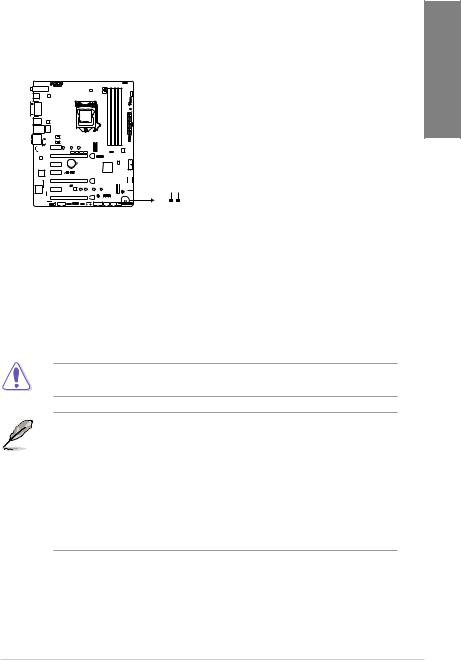
1.1.6Jumpers and holes
|
1. Clear RTC RAM jumper (2-pin CLRTC) |
||
|
This jumper allows you to clear the Real Time Clock (RTC) RAM in CMOS. You can |
||
|
clear the CMOS memory of date, time, and system setup parameters by erasing the |
1 |
|
|
CMOS RTC RAM data. The onboard button cell battery powers the RAM data in |
||
|
Chapter |
||
|
CMOS, which include system setup information such as system passwords. |
||
STRIX Z370-E GAMING
CLRTC
+3V_BAT GND
PIN 1
ROG STRIX Z370-E GAMING Clear RTC RAM
To erase the RTC RAM:
1.Turn OFF the computer and unplug the power cord.
2.Short-circuit pin 1-2 with a metal object or jumper cap for about 5-10 seconds.
3.Plug the power cord and turn ON the computer.
4.Hold down the <Delete> key during the boot process and enter BIOS setup to re-enter data.
Except when clearing the RTC RAM, never remove the cap on CLRTC jumper default position. Removing the cap will cause system boot failure!
•If the steps above do not help, remove the onboard battery and move the jumper
again to clear the CMOS RTC RAM data. After the CMOS clearance, reinstall the battery.
•You do not need to clear the RTC when the system hangs due to overclocking. For system failure due to overclocking, use the C.P.R. (CPU Parameter Recall) feature. Shut down and reboot the system so the BIOS can automatically reset parameter settings to default values.
•Due to the chipset behavior, AC power off is required to enable C.P.R. function. You must turn off and on the power supply or unplug and plug the power cord before rebooting the system.
|
ASUS ROG STRIX Z370-E GAMING |
1-9 |
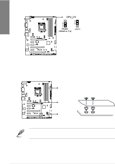
|
2. |
CPU over voltage jumper (3-pin CPU_OV) |
|
The CPU over voltage jumper allows you to set a higher CPU voltage for a flexible |
|
|
overclocking system, depending on the type of the installed CPU. To gain more CPU |
|
|
1 Chapter |
voltage setting, insert the jumper to pins 2-3. To go back to its default CPU voltage |
|
setting, insert the jumper to pins 1-2. |
|
STRIX Z370-E GAMING
ROG STRIX Z370-E GAMING CPU_OV setting
3.3D Mount
Secure 3D printed parts to these 3D Mount holes for a personalized motherboard.
3D Mount 
3D Mount 
STRIX Z370-E GAMING
3D Mount 
ROG STRIX Z370-E GAMING 3D Printing Mount
•Download 3D source files at http://www.asus.com.
•Use the bundled 3D Mount screws to install the 3D printed parts.
|
1-10 |
Chapter 1: Product Introduction |
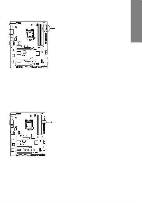
1.1.7Onboard LEDs
1.POST State LEDs
The POST State LEDs provide the status of these key components during POST (Power-On Self-Test): CPU, memory modules, VGA card, and hard disk drives. If an error is found, the critical component’s LED stays lit up until the problem is solved.
 BOOT (YELLOW GREEN)
 VGA (WHITE)
 DRAM (YELLOW)
 CPU (RED)
STRIX Z370-E GAMING
ROG STRIX Z370-E GAMING
CPU/DRAM/BOOT_DEVICE/VGA LED
2.Standby Power LED
The motherboard comes with a standby power LED. The LED lights up to indicate that the system is ON, in sleep mode, or in soft-off mode. This is a reminder that you should shut down the system and unplug the power cable before removing or plugging in any motherboard component. The illustration below shows the location of the onboard LED.
STRIX Z370-E GAMING
ROG STRIX Z370-E GAMING PWR_LED
Chapter 1
|
ASUS ROG STRIX Z370-E GAMING |
1-11 |
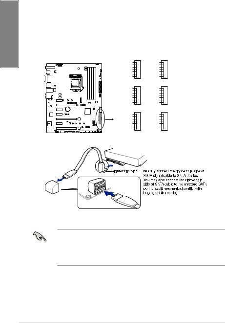
1.1.8Internal connectors
|
1. |
Intel® Serial ATA 6 Gb/s connectors (7-pin SATA6G_12, SATA 6G_34, SATA |
||
|
Chapter |
6G_56) |
||
|
These connectors connect to Serial ATA 6 Gb/s hard disk drives via Serial ATA 6 Gb/s |
|||
|
Z370 chipset. |
|||
|
signal cables. |
|||
|
If you installed Serial ATA hard disk drives, you can create a RAID 0, 1, 5, and 10 |
|||
|
configuration with the Intel® Rapid Storage Technology through the onboard Intel® |
|||
|
1 |
|||
|
SATA6G_1 |
SATA6G_2 |
||
|
GND |
GND |
||
|
RSATA_TXP1 |
RSATA_TXP2 |
||
|
RSATA_TXN1 |
RSATA_TXN2 |
||
|
GND |
GND |
||
|
RSATA_RXN1 |
RSATA_RXN2 |
||
|
RSATA_RXP1 |
RSATA_RXP2 |
||
|
GND |
GND |
||
|
SATA6G_3 |
SATA6G_4 |
||
|
GND |
GND |
||
|
RSATA_TXP3 |
RSATA_TXP4 |
||
|
RSATA_TXN3 |
RSATA_TXN4 |
||
|
GND |
GND |
||
|
RSATA_RXN3 |
RSATA_RXN4 |
||
|
RSATA_RXP3 |
RSATA_RXP4 |
||
|
GND |
GND |
||
|
SATA6G_5 |
SATA6G_6 |
||
|
GND |
GND |
||
|
STRIX Z370-E GAMING |
RSATA_TXP5 |
RSATA_TXP6 |
|
|
RSATA_TXN5 |
RSATA_TXN6 |
||
|
GND |
GND |
||
|
RSATA_RXN5 |
RSATA_RXN6 |
||
|
RSATA_RXP5 |
RSATA_RXP6 |
||
|
GND |
GND |
ROG STRIX Z370-E GAMING Intel® SATA 6 Gb/s connectors
•These connectors are set to [AHCI] by default. If you intend to create a Serial ATA RAID set using these connectors, set the SATA Mode item in the BIOS to [Intel RST Premium With Intel Optane System Acceleration (RAID)].
•Before creating a RAID set, refer to the manual bundled in the motherboard support DVD.
|
1-12 |
Chapter 1: Product Introduction |

2.Front panel audio connector (10-1 pin AAFP)
This connector is for a chassis-mounted front panel audio I/O module that supports HD Audio. Connect one end of the front panel audio I/O module cable to this connector.
|
AGND |
NC SENSE1 RETUR |
SENSE2 RETUR |
Chapter 1 |
|
|
AAFP |
SENSESEND PORT2 L |
|||
|
STRIX Z370-E GAMING |
PORT1 L |
PORT1 R PORT2 R |
||
|
HD-audio-compliant |
||||
|
pin definition |
ROG STRIX Z370-E GAMING Analog front panel connector
We recommend that you connect a high-definition front panel audio module to this connector to avail of the motherboard’s high-definition audio capability.
3.USB 3.1 Gen2 front panel connector (U31G2_E3)
This connector allows you to connect a USB 3.1 Gen2 module for additional USB 3.1 Gen2 ports. The latest USB 3.1 Gen2 connectivity provides data transfer speeds of up to 10 Gbps. The next-generation standard is completely backward-compatible with your existing USB devices.
U31G2_E3
|
SBU2 |
|
|
SBU1 |
|
|
CC1 |
|
|
VBUS |
|
|
RX1- |
|
|
RX1+ |
|
|
GND |
|
|
TX1- |
|
|
TX1+ |
|
|
STRIX Z370-E GAMING |
VBUS |
ROG STRIX Z370-E GAMING USB 3.1 Gen 2 front panel connector
|
ASUS ROG STRIX Z370-E GAMING |
1-13 |
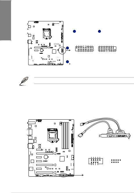
1 Chapter
4.USB 3.1 Gen1 connectors (20-1 pin U31G1_12, U31G1_34)
These connectors allow you to connect a USB 3.1 Gen1 module for additional USB 3.1 Gen1 front or rear panel ports. With an installed USB 3.1 Gen1 module, you can enjoy all the benefits of USB 3.1 Gen1 including faster data transfer speeds of up to 5 Gb/s, faster charging time for USB-chargeable devices, optimized power efficiency, and backward compatibility with USB 2.0.
|
A U31G1_12 |
B U31G1_34 |
||||||||||||||||||||||||||||||||
|
PIN 1 |
Vbus IntA P1 SSRX- |
IntA P1 SSRX+ GND IntA P1 SSTXIntA P1 SSTX+ GND IntA P1 D- IntA P1 D+ |
GND |
IntA P2 D+ IntA P2 D- GND IntA P2 SSTX+ IntA P2 SSTXGND IntA P2 SSRX+ IntA P2 SSRXVbus |
|||||||||||||||||||||||||||||
PIN 1
|
B |
Vbus SSRXP2IntASSRX+P2IntA GND SSTXP2IntASSTX+P2IntA GND P2IntADP2IntAD+ |
GND P1IntAD+ P1IntADGND SSTX+P1IntA SSTXP1IntAGND SSRX+P1IntA SSRXP1IntAVbus |
|||||||||||||||||||||||||||
|
STRIX Z370-E GAMING |
|||||||||||||||||||||||||||||
ROG STRIX Z370-E GAMING USB 3.1 Gen 1 connectors
The USB 3.1 Gen1 module is purchased separately.
5.USB 2.0 connectors (10-1 pin USB910, USB1112)
These connectors are for USB 2.0 ports. Connect the USB module cable to these connectors, then install the module to a slot opening at the back of the system chassis. This USB connector complies with USB 2.0 specification that supports up to 480 Mb/s connection speed.
|
USB910 |
||
|
USB+5V USB P10USB P10+ |
GND NC |
|
|
STRIX Z370-E GAMING |
||
|
PIN 1 |
USB+5V USB P9USB P9+ |
GND |
USB1112
|
USB+5V USB P12USB P12+ |
GND NC |
||||||
|
PIN 1 |
USB+5V USB P11USB P11+ |
GND |
|||||
ROG STRIX Z370-E GAMING USB2.0 connectors
|
1-14 |
Chapter 1: Product Introduction |
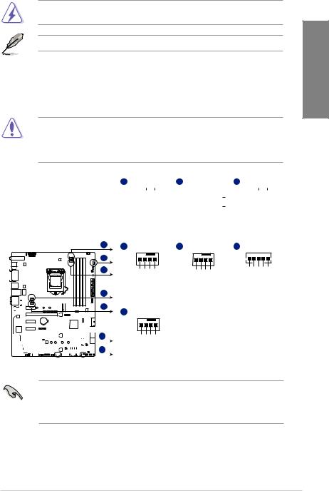
DO NOT connect a 1394 cable to the USB connectors. Doing so will damage the motherboard!
The USB 2.0 module is purchased separately.
6.CPU, CPU optional, AIO pump, M.2, extension, and chassis fan connectors (4-pin CPU_FAN; 4-pin CPU_OPT; 4-pin AIO_PUMP; 4-pin M.2_FAN; 5-pin EXT_FAN; 4-pin CHA_FAN1-2)
Connect the fan cables to the fan connectors on the motherboard, ensuring that the black wire of each cable matches the ground pin of the connector.
•DO NOT forget to connect the fan cables to the fan connectors. Insufficient air flow
inside the system may damage the motherboard components. These are not jumpers! Do not place jumper caps on the fan connectors!
•Ensure that the CPU fan cable is securely installed to the CPU fan connector.
|
A CPU_FAN |
B CHA_FAN1 C CPU_OPT |
|||||||||||||||||
|
CHA FAN PWM |
||||||||||||||||||
|
CHA FAN IN |
||||||||||||||||||
|
CHA FAN PWR |
||||||||||||||||||
|
CPU FAN PWM CPU FAN IN CPU FAN PWR GND |
GND |
CPU FAN PWM CPU FAN IN CPU FAN PWR GND |
||||||||||||||||
|
A |
D CHA_FAN2 |
E AIO_PUMP |
F EXT_FAN |
||
|
B |
PWMFANCHA |
INFANCHA PWRFANCHA GND |
PWMPUMPAIO INPUMPAIO PWRPUMPAIO GND |
GND Control2 Control1 Sense2 Sense1 |
|
|
C |
|||||
|
D |
|||||
|
E |
G M.2_FAN |
||||
STRIX Z370-E GAMING
|
F |
M.2PWM |
M.2IN M.2PWR GND |
||||||||||||||||||||
|
G |
||||||||||||||||||||||
ROG STRIX Z370-E GAMING Fan connectors
•The CPU_FAN connector supports the CPU fan of maximum 1A (12 W) fan power.
•The EXT_FAN connector supports 2 of 5 thermal sensor sources.
•Connect the fan of your water cooling kit to the AIO_PUMP connector.
Chapter 1
|
ASUS ROG STRIX Z370-E GAMING |
1-15 |
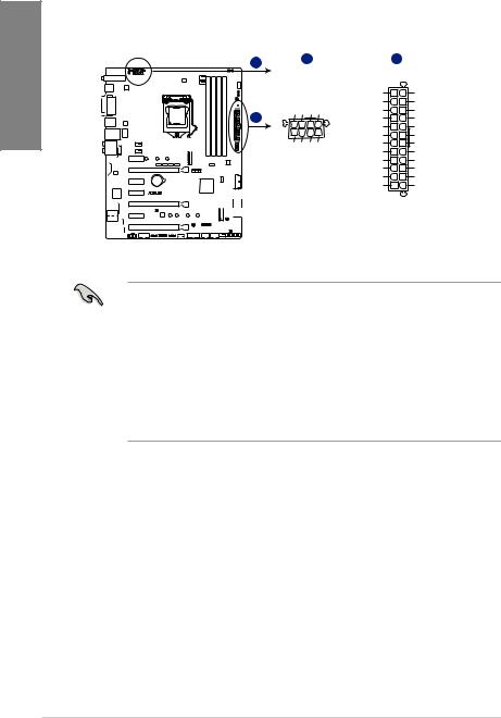
1 Chapter
7.ATX power connectors (24-pin EATXPWR; 8-pin EATX12V)
These connectors are for ATX power supply plugs. The power supply plugs are designed to fit these connectors in only one orientation. Find the proper orientation and push down firmly until the connectors completely fit.
|
A |
B |
|||
|
EATX12V |
EATXPWR |
|||
|
DC DC DC DC |
+3 Volts |
GND |
||
|
+12V +12V +12V +12V |
+12 |
Volts |
+5 Volts |
|
|
+12 |
Volts |
+5 Volts |
||
|
+5V Standby |
+5 Volts |
|||
|
Power OK |
-5 Volts |
|||
|
PIN 1 |
GND |
GND |
||
|
+5 Volts |
GND |
|||
|
GND GND GND GND |
||||
|
GND |
GND |
|||
|
+5 Volts |
PSON# |
|||
|
GND |
GND |
|||
|
+3 |
Volts |
-12 Volts |
||
|
+3 |
Volts |
+3 Volts |
||
|
PIN 1 |
ROG STRIX Z370-E GAMING ATX power connectors
•For a fully configured system, we recommend that you use a power supply unit (PSU) that complies with ATX 12 V Specification 2.0 (or later version) and provides a minimum power of 350 W.
•DO NOT forget to connect the 8-pin EATX12V power plug. Otherwise, the system will not boot.
•We recommend that you use a PSU with a higher power output when configuring a system with more power-consuming devices. The system may become unstable or may not boot up if the power is inadequate.
•If you want to use two or more high-end PCI Express x16 cards, use a PSU with 1000W power or above to ensure the system stability.
|
1-16 |
Chapter 1: Product Introduction |
![]()
8.System panel connector (20-3 pin PANEL)
This connector supports several chassis-mounted functions.
PLED 
 PWRSW
PWRSW 
 SPEAKER
|
PLED+ PLEDPWRBTN# GND |
|||||||||||||
|
+5V Ground Ground Speaker Intruder# |
|||||||||||||
|
CHASSIS |
|||||||||||||
|
PIN 1 |
HDDLED- |
Ground RSTCON# NC |
PLED+ |
PLED- |
|
|
HDDLED+ |
GND |
||||
|
STRIX Z370-E GAMING |
|||||
|
HDD_LED |
RESET |
PLED |
ROG STRIX Z370-E GAMING System panel connector
•System power LED (2-pin or 3-1 pin PLED)
The 2-pin or 3-1 pin connector is for the system power LED. Connect the chassis power LED cable to this connector. The system power LED lights up when you turn on the system power, and blinks when the system is in sleep mode.
•Hard disk drive activity LED (2-pin HDD_LED)
This 2-pin connector is for the HDD Activity LED. Connect the HDD Activity LED cable to this connector. The HDD LED lights up or flashes when data is read from or written to the HDD.
•System warning speaker (4-pin SPEAKER)
This 4-pin connector is for the chassis-mounted system warning speaker. The speaker allows you to hear system beeps and warnings.
•ATX power button/soft-off button (2-pin PWRSW)
This connector is for the system power button. Pressing the power button turns the system on or puts the system in sleep or soft-off mode depending on the operating system settings. Pressing the power switch for more than four seconds while the system is ON turns the system OFF.
•Reset button (2-pin RESET)
This 2-pin connector is for the chassis-mounted reset button for system reboot without turning off the system power.
•Chassis intrusion connector (2-pin CHASSIS)
This connector is for a chassis-mounted intrusion detection sensor or switch. Connect one end of the chassis intrusion sensor or switch cable to this connector. The chassis intrusion sensor or switch sends a high-level signal to this connector when a chassis component is removed or replaced. The signal is then generated as a chassis intrusion event.
Chapter 1
|
ASUS ROG STRIX Z370-E GAMING |
1-17 |

1 Chapter
9.TPM connector (14-1 pin TPM)
This connector supports a Trusted Platform Module (TPM) system, which securely stores keys, digital certificates, passwords and data. A TPM system also helps enhance network security, protect digital identities, and ensures platform integrity.
|
TPM |
||
|
F CLKRUN F SERIRQ F FRAME# F LAD3 F LAD2 F LAD1 F LAD0 |
||
|
PIN 1 |
||
|
STRIX Z370-E GAMING |
+3VSB |
PCIRST#S TBD GND PCICLKC TPM +3V +3V |
ROG STRIX Z370-E GAMING TPM connector
The TPM module is purchased separately.
10.Serial port connector (10-1 pin COM)
This connector is for a serial (COM) port. Connect the serial port module cable to this connector, then install the module to a slot opening at the back of the system chassis.
CTS1
DSR1
DTR1
RXD1
|
STRIX Z370-E GAMING |
COM |
|
PIN 1 |
|
|
DCD1 TXD1 GND RTS1# PI1# |
ROG STRIX Z370-E GAMING Serial port connector
The COM module is purchased separately.
|
1-18 |
Chapter 1: Product Introduction |
 Loading…

-
Contents
-
Table of Contents
-
Bookmarks
Quick Links
Related Manuals for Asus ROG STRIX Z370-E GAMING
Summary of Contents for Asus ROG STRIX Z370-E GAMING
-
Page 1
STRIX Z370-E GAMING… -
Page 2
INCIDENTAL, OR CONSEQUENTIAL DAMAGES (INCLUDING DAMAGES FOR LOSS OF PROFITS, LOSS OF BUSINESS, LOSS OF USE OR DATA, INTERRUPTION OF BUSINESS AND THE LIKE), EVEN IF ASUS HAS BEEN ADVISED OF THE POSSIBILITY OF SUCH DAMAGES ARISING FROM ANY DEFECT OR ERROR IN THIS MANUAL OR PRODUCT. -
Page 3: Table Of Contents
Contents Safety information …………………. vi About this guide ………………….vii ……….. ix Package contents ………………… xiii Installation tools and components …………….. xiv Chapter 1: Product Introduction Motherboard overview …………….1-1 1.1.1 Before you proceed …………..1-1 1.1.2 Motherboard layout …………..1-2 1.1.3 Central Processing Unit (CPU) ………..
-
Page 4
HDD/SSD SMART Information ……….3-19 …………..3-19 Monitor menu ………………. 3-20 Boot menu ………………..3-20 Tool menu ………………..3-22 3.9.1 ASUS EZ Flash 3 Utility …………3-22 3.9.2 Secure Erase …………….3-22 …………3-24 3.9.4 ASUS SPD Information …………. 3-24 3.9.5… -
Page 5
Rapid Storage Technology in UEFI BIOS ……4-2 ® 4.1.4 Intel Rapid Storage Technology Option ROM utility ….4-6 Creating a RAID driver disk…………..4-10 ® 4.2.1 Creating a RAID driver disk in Windows ……… 4-10 Appendix Notices ……………………A-1 ASUS contact information ………………A-7… -
Page 6: Safety Information
Safety information Electrical safety before relocating the system. When adding or removing devices to or from the system, ensure that the power cables for the devices are unplugged before the signal cables are connected. If possible, disconnect all power cables from the existing system before you add a device. Before connecting or removing signal cables from the motherboard, ensure that all power cables are unplugged.
-
Page 7: About This Guide
Refer to the following sources for additional information and for product and software updates. ASUS website The ASUS website (www.asus.com) provides updated information on ASUS hardware and software products. Optional documentation that may have been added by your dealer. These documents are not part of the…
-
Page 8
Conventions used in this guide To ensure that you perform certain tasks properly, take note of the following symbols used throughout this manual. DANGER/WARNING: Information to prevent injury to yourself when trying to complete a task. CAUTION: Information to prevent damage to the components when trying to complete a task. -
Page 9
® Supports AMD 3-Way CrossFireX™ Technology 1 x ASUS Wi-Fi module (Wi-Fi 802.11 a/b/g/n/ac and Bluetooth v4.2) 2 x USB3.1 Gen2 ports (1 x Type-A [red] and 1 x Type-C ports at back panel) 1 x DVI port 1 x HDMI port… -
Page 10
Processors. Before using Intel ® Optane memory modules, ensure that you have updated your motherboard drivers and BIOS to the latest version from ASUS support website. — Impedance sense for front and rear headphone outputs — High quality 120dB SNR stereo playback output and 113 dB SNR… -
Page 11
Digi+VRM — EPU — Auto Tuning, TPU, GPU Boost Fan Xpert 4 featuring Fan Auto Tuning function and multiple ASUS EZ DIY — ASUS CrashFree BIOS 3 — ASUS EZ Flash 3 ASUS Q-Design ASUS Special — Q-Shield Features… -
Page 12
1 x Clear CMOS jumper (2-pin) 128 Mb Flash ROM, UEFI AMI BIOS, PnP, WfM2.0, SM BIOS 3.0, ACPI 6.0, Multi-language BIOS, ASUS EZ Flash 3, CrashFree BIOS 3, F11 EZ Tuning BIOS Features F12 PrintScreen and ASUS DRAM SPD (Serial Presence Detect) memory information WfM2.0, DMI3.0, WOL by PME, PXE… -
Page 13: Package Contents
1 x RGB LED extension cable 1 x Addressable LED extension cable 1 x Thermal sensor cable 1 x I/O shield 1 x ASUS 2T2R dual band Wi-Fi moving antennas (Wi-Fi 802.11a/b/g/n/ac compliant) 1 x CPU Installation tool 1 x ROG cable label…
-
Page 14: Installation Tools And Components
Installation tools and components Intel ® 1151 CPU ® Intel 1151 compatible CPU Fan SATA hard disk drive PC chassis 1 bag of screws DIMM Power supply unit Graphics card The tools and components listed above are not included in the motherboard package.
-
Page 15: Chapter 1: Product Introduction
Chapter 1: Product Introduction Product Introduction Motherboard overview 1.1.1 Before you proceed ASUS ROG STRIX Z370-E GAMING…
-
Page 16: Motherboard Layout
1.1.2 Motherboard layout 24.4cm(9.6in) CPU_OV RGB_HEADER2 CPU_FAN EATX12V M.2(WIFI) DIGI+ CHA_FAN1 CPU_OPT USB31G2_EC1 USB31G2_E2 3142 BOOT_DEVICE_LED VGA_LED DRAM_LED CPU_LED MOUNT PWR_LED LGA1151 HDMI USB1314 1442K LAN1_U31G1_56 CHA_FAN2 AUDIO AIO_PUMP PCIE_X1_1 2280 2260 2242 3142 ASM1480 ASM1480 ASM1480 ASM1480 ASM1480 M.2_2(SOCKET3) PCIE_X16/X8_1 PCIE SATA IRST…
-
Page 17
Layout contents Connectors/Jumpers/Buttons and switches/Slots Page 1-17 1-20 1-10 1-13 1-19 ® 1-12 1-17 1-21 1-13 1-19 1-10 ASUS ROG STRIX Z370-E GAMING… -
Page 18: Central Processing Unit (Cpu)
1.1.3 Central Processing Unit (CPU) ® ® STRIX Z370-E GAMING ROG STRIX Z370-E GAMING CPU LGA1151 Chapter 1: Product Introduction…
-
Page 19: System Memory
1.1.4 System memory ® STRIX Z370-E GAMING ROG STRIX Z370-E GAMING 288-pin DDR4 DIMM sockets ASUS ROG STRIX Z370-E GAMING…
-
Page 20
® ® ® ® Chapter 1: Product Introduction… -
Page 21: Expansion Slots
1.1.5 Expansion slots PCIE_X1_1 PCIE_X16/X8_1 PCIE_X1_2 ® PCIE_X1_3 STRIX Z370-E GAMING PCIE_X8_2 PCIE_X1_4 PCIE_X4 Slot No. Slot Description ASUS ROG STRIX Z370-E GAMING…
-
Page 22
PCI Express 3.0 operating mode PCIe_x16/x8_1 PCIe_x8_2 PCI Express 3.0 operating mode Hyper M.2 X16 card PCIe_x16/x8_1 PCIe_x8_2 ® ® Chapter 1: Product Introduction… -
Page 23: Jumpers And Holes
1.1.6 Jumpers and holes Clear RTC RAM jumper (2-pin CLRTC) CLRTC ® STRIX Z370-E GAMING PIN 1 ROG STRIX Z370-E GAMING Clear RTC RAM ASUS ROG STRIX Z370-E GAMING…
-
Page 24
CPU over voltage jumper (3-pin CPU_OV) ® STRIX Z370-E GAMING ROG STRIX Z370-E GAMING CPU_OV setting 3D Mount 3D Mount 3D Mount ® STRIX Z370-E GAMING 3D Mount ROG STRIX Z370-E GAMING 3D Printing Mount Chapter 1: Product Introduction 1-10… -
Page 25: Onboard Leds
POST State LEDs BOOT (YELLOW GREEN) VGA (WHITE) DRAM (YELLOW) CPU (RED) ® STRIX Z370-E GAMING ROG STRIX Z370-E GAMING CPU/DRAM/BOOT_DEVICE/VGA LED Standby Power LED PWR_LED ® STRIX Z370-E GAMING ROG STRIX Z370-E GAMING PWR_LED ASUS ROG STRIX Z370-E GAMING 1-11…
-
Page 26: Internal Connectors
RSATA_RXP4 SATA6G_5 SATA6G_6 ® STRIX Z370-E GAMING RSATA_TXP5 RSATA_TXP6 RSATA_TXN5 RSATA_TXN6 RSATA_RXN5 RSATA_RXN6 RSATA_RXP5 RSATA_RXP6 ROG STRIX Z370-E GAMING Intel ® SATA 6 Gb/s connectors [AHCI] [Intel RST Premium With Intel Optane System Acceleration (RAID)] Chapter 1: Product Introduction 1-12…
-
Page 27
USB 3.1 Gen2 front panel connector (U31G2_E3) U31G2_E3 VBUS SBU2 TX2+ SBU1 TX2- VBUS RX2+ RX1- RX2- RX1+ TX1- TX1+ ® STRIX Z370-E GAMING VBUS ROG STRIX Z370-E GAMING USB 3.1 Gen 2 front panel connector ASUS ROG STRIX Z370-E GAMING 1-13… -
Page 28
USB 3.1 Gen1 connectors (20-1 pin U31G1_12, U31G1_34) U31G1_12 U31G1_34 PIN 1 PIN 1 ® STRIX Z370-E GAMING ROG STRIX Z370-E GAMING USB 3.1 Gen 1 connectors USB 2.0 connectors (10-1 pin USB910, USB1112) USB910 USB1112 ® STRIX Z370-E GAMING PIN 1 PIN 1 ROG STRIX Z370-E GAMING USB2.0 connectors… -
Page 29
CPU_FAN; 4-pin CPU_OPT; 4-pin AIO_PUMP; 4-pin M.2_FAN; 5-pin EXT_FAN; 4-pin CHA_FAN1-2) CPU_FAN CHA_FAN1 CPU_OPT CHA FAN PWM CHA FAN IN CHA FAN PWR CHA_FAN2 AIO_PUMP EXT_FAN M.2_FAN ® STRIX Z370-E GAMING ROG STRIX Z370-E GAMING Fan connectors ASUS ROG STRIX Z370-E GAMING… -
Page 30
+5V Standby +5 Volts -5 Volts Power OK PIN 1 +5 Volts +5 Volts PSON# +3 Volts -12 Volts +3 Volts +3 Volts PIN 1 ® STRIX Z370-E GAMING ROG STRIX Z370-E GAMING ATX power connectors Chapter 1: Product Introduction 1-16… -
Page 31
System panel connector (20-3 pin PANEL) PLED PWRSW SPEAKER CHASSIS PANEL PIN 1 ® STRIX Z370-E GAMING HDD_LED RESET PLED ROG STRIX Z370-E GAMING System panel connector ASUS ROG STRIX Z370-E GAMING 1-17… -
Page 32
TPM connector (14-1 pin TPM) PIN 1 ® STRIX Z370-E GAMING ROG STRIX Z370-E GAMING TPM connector Serial port connector (10-1 pin COM) ® STRIX Z370-E GAMING PIN 1 ROG STRIX Z370-E GAMING Serial port connector Chapter 1: Product Introduction… -
Page 33
2280 2260 2242 M.2_1(SOCKET3) ® STRIX Z370-E GAMING 2280 2260 2242 ROG STRIX Z370-E GAMING M.2 sockets ® Thermal sensor connector (2-pin T_SENSOR) ® STRIX Z370-E GAMING T_SENSOR PIN 1 SENSOR IN ROG STRIX Z370-E GAMING T_SENSOR connector ASUS ROG STRIX Z370-E GAMING… -
Page 34
RGB headers (4-pin RGB_HEADER1-2) RGB_HEADER2 PIN 1 +12V G R B RGB_HEADER1 PIN 1 +12V G R B ® STRIX Z370-E GAMING ROG STRIX Z370-E GAMING RGB_HEADER connectors Chapter 1: Product Introduction 1-20… -
Page 35
Addressable RGB header (4-1 pin ADD_HEADER) ® STRIX Z370-E GAMING ROG STRIX Z370-E GAMING EXTREME ADD header ASUS ROG STRIX Z370-E GAMING 1-21… -
Page 36
Chapter 1: Product Introduction 1-22… -
Page 37: Chapter 2: Basic Installation
2.1.1 Motherboard installation Install the ASUS Q-Shield to the chassis rear I/O panel. Place the motherboard into the chassis, ensuring that its rear I/O ports are aligned to the chassis’ rear I/O panel.
-
Page 38
Place nine (9) screws into the holes indicated by circles to secure the motherboard to the chassis. ® STRIX Z370-E GAMING DO NOT overtighten the screws! Doing so can damage the motherboard. Chapter 2: Basic Installation… -
Page 39: Cpu Installation
Ensure that you install the correct CPU designed for LGA1151 socket only. DO NOT install a CPU designed for LGA1155 and LGA1156 sockets on the LGA1151 socket. Top of CPU Bottom of CPU Bottom of CPU ASUS ROG STRIX Z370-E GAMING…
-
Page 40
Top of CPU ® LGA1151 socket. on the motherboard. the CPU Installation Tool. picking up the CPU Installation Tool. Tool to prevent CPU damage. incorrect CPU orientation/placement, or other damages resulting from negligence by the user. Chapter 2: Basic Installation… -
Page 41: Cpu Heatsink And Fan Assembly Installation
2.1.3 CPU heatsink and fan assembly installation Apply the Thermal Interface Material to the CPU heatsink and CPU before you install the heatsink and fan, if necessary. To install the CPU heatsink and fan assembly ASUS ROG STRIX Z370-E GAMING…
-
Page 42
To uninstall the CPU heatsink and fan assembly Chapter 2: Basic Installation… -
Page 43: Dimm Installation
2.1.4 DIMM installation To remove a DIMM ASUS ROG STRIX Z370-E GAMING…
-
Page 44: Atx Power Connection
2.1.5 ATX power connection Ensure to connect the 8-pin power plug. Chapter 2: Basic Installation…
-
Page 45: Sata Device Connection
2.1.6 SATA device connection ASUS ROG STRIX Z370-E GAMING…
-
Page 46: Front I/O Connector
2.1.7 Front I/O connector To install USB 3.1 Gen2 connector To install front panel connector USB 3.1 Gen2 orientation. Push the connector until it clicks into place. To install USB 3.1 Gen1 connector To install USB 2.0 connector USB 3.1 Gen1 USB 2.0 To install front panel audio connector AAFP…
-
Page 47: Expansion Card Installation
2.1.8 Expansion card installation To install PCIe x16 cards To install PCIe x1 cards ASUS ROG STRIX Z370-E GAMING 2-11…
-
Page 48
To install HYPER M.2 x4 card The SSD card is purchased separately. Chapter 2: Basic Installation 2-12… -
Page 49: M.2 Installation
2.1.9 M.2 installation ASUS ROG STRIX Z370-E GAMING 2-13…
-
Page 50
Supported M.2 type varies per motherboard. Use the bundled M.2 screws to secure the M.2. Chapter 2: Basic Installation 2-14… -
Page 51: Wi-Fi Antenna Installation
2.1.10 Wi-Fi antenna installation Installing the ASUS 2×2 dual band W-Fi antenna back of the chassis. ports. The illustration above is for reference only. The I/O port layout may vary with models, but ASUS ROG STRIX Z370-E GAMING 2-15…
-
Page 52: Fan Holder Installation
2.1.11 Fan holder installation To install the Fan holder and fan ® STRIX Z370-E GAMING for additional fan(s). Chapter 2: Basic Installation 2-16…
-
Page 53: Motherboard Rear And Audio Connections
Motherboard rear and audio connections 2.2.1 Rear I/O connection Rear panel connectors DisplayPort V4.2* HDMI 1.4b port DVI-D port Intel ® LAN port (LAN1)** Audio I/O ports*** ® version. on the operating system’s setting. ASUS ROG STRIX Z370-E GAMING 2-17…
-
Page 54
** LAN ports LED indications Activity Link LED Speed LED Status Description Status Description ACT/LINK SPEED No link 10 Mbps connection Orange Linked Orange 100 Mbps connection Data activity Green 1 Gbps connection Ready to wake up LAN port then steady) from S5 mode LEDs may continue to blink even when disabled. -
Page 55: Audio I/O Connections
2.2.2 Audio I/O connections Audio I/O ports Connect to Headphone and Mic Connect to Stereo Speakers Connect to 2 channel Speakers ASUS ROG STRIX Z370-E GAMING 2-19…
-
Page 56
Connect to 4 channel Speakers Connect to 6 channel Speakers Chapter 2: Basic Installation 2-20… -
Page 57
If you do not see anything within 30 seconds from the time you turned on the power, the system may have failed a power-on test. Check the jumper settings and connections or call your retailer for assistance. ASUS ROG STRIX Z370-E GAMING 2-21… -
Page 58: Turning Off The Computer
BIOS Beep Description One short beep VGA detected Quick boot set to disabled No keyboard detected One continuous beep followed by two No memory detected short beeps then a pause (repeated) One continuous beep followed by three No VGA detected short beeps One continuous beep followed by four Hardware component failure…
-
Page 59: Chapter 3: Bios Setup
Chapter 3: BIOS Setup BIOS Setup Knowing BIOS DO NOT change the default BIOS settings We strongly recommend that you change the BIOS settings only with the help of a trained service personnel Z370EGAM.CAP ASUS ROG STRIX Z370-E GAMING…
-
Page 60: Bios Setup Program
BIOS setup program Entering BIOS at startup Entering BIOS Setup after POST Load Optimized Defaults Exit <F5> 3.10 Exit Menu 1.1.6 Jumpers and holes BIOS menu screen EZ Mode Advanced Mode Setup Mode in Boot menu Chapter 3: BIOS Setup…
-
Page 61: Ez Mode
Displays the CPU Fan’s speed. Click the button to manually tune the fans Click to go to Advanced mode Loads optimized Search on the FAQ default settings Click to display boot devices Selects the boot device priority ASUS ROG STRIX Z370-E GAMING…
-
Page 62: Advanced Mode
3.2.2 Advanced Mode Advanced Mode(F7) Hot Keys Pop-up Menu Scroll bar Menu bar MyFavorite(F3) Language Qfan Control(F6) EZ Tuning Wizard(F11) Go back to EZ Mode Menu items General help Search on the FAQ Displays the CPU temperature, CPU, and memory voltage output Chapter 3: BIOS Setup…
-
Page 63
Menu bar My Favorites Main Ai Tweaker Advanced Monitor Boot Tool Exit Menu items Main Submenu items Language My Favorites(F3) 3.3 My Favorites Q-Fan Control(F6) 3.2.3 QFan Control EZ Tuning Wizard(F11) 3.2.4 EZ Tuning Wizard ASUS ROG STRIX Z370-E GAMING… -
Page 64
Search on FAQ Hot keys Scroll bar General help Chapter 3: BIOS Setup… -
Page 65: Qfan Control
Click to select a fan to be Click to activate Click to activate DC Mode PWM Mode Click to apply the fan setting apply to your fans Click to undo the Click to go back to main menu changes your fans ASUS ROG STRIX Z370-E GAMING…
-
Page 66
Manual Speed points Select to manually Apply Exit (ESC) Chapter 3: BIOS Setup… -
Page 67
3.2.4 EZ Tuning Wizard OC setup RAID setup OC Tuning Next Daily Computing Gaming/Media Editing, Next ASUS ROG STRIX Z370-E GAMING… -
Page 68
BOX cooler, Tower cooler, Water cooler, I’m not sure, Next Next Creating RAID RAID Next ® PCIE SATA Next Chapter 3: BIOS Setup 3-10… -
Page 69
Easy Backup Super Speed Next Next Easy Backup (RAID1) Easy Backup (RAID10) Next Super Speed (RAID0) Super Speed (RAID5) Next ASUS ROG STRIX Z370-E GAMING 3-11… -
Page 70: My Favorites
My Favorites Chapter 3: BIOS Setup 3-12…
-
Page 71
Adding items to My Favorites Main menu panel Selected shortcut items Submenu panel Delete all favorite items Recover to default favorite items Exit (ESC) ASUS ROG STRIX Z370-E GAMING 3-13… -
Page 72: Main Menu
Main menu Security 1.1.6 Jumpers and holes [Not Installed] [Installed] Ai Tweaker menu Ai Overclock Tuner [Manual] BCLK Frequency Chapter 3: BIOS Setup 3-14…
-
Page 73
ASUS MultiCore Enhancement CPU Core Ratio DRAM Odd Ratio Mode DRAM Frequency [TPU II]. Internal CPU Power Management Intel(R) SpeedStep(tm) Turbo Mode ASUS ROG STRIX Z370-E GAMING 3-15… -
Page 74: Advanced Menu
Advanced menu Hyper-threading CPU — Power Management Control Intel(R) SpeedStep(tm) Turbo Mode CPU C states CFG Lock Chapter 3: BIOS Setup 3-16…
-
Page 75
PCIe Speed Not Present SATA Controller(s) SATA Mode Selection SMART Self Test ASUS ROG STRIX Z370-E GAMING… -
Page 76
SATA6G_1(Charcoal Black) — SATA6G_6(Charcoal Black) SATA6G_1(Charcoal Black) — SATA6G_6(Charcoal Black) Hot Plug AHCI Hyper M.2X16 [Enabled][Disabled] HD Audio Controller RGB LED lighting Chapter 3: BIOS Setup 3-18… -
Page 77: Hdd/Ssd Smart Information
Intel LAN Controller USB Type C Power Switch ErP Ready [Enabled] 3.6.10 HDD/SSD SMART Information The Mass Storage Devices None USB Single Port Control 1.1.2 Motherboard layout ASUS ROG STRIX Z370-E GAMING 3-19…
-
Page 78: Monitor Menu
Monitor menu Qfan Tuning Boot menu Fast Boot [Enabled] Next Boot after AC Power Loss Setup Mode CSM (Compatibility Support Module) Launch CSM ® ® Chapter 3: BIOS Setup 3-20…
-
Page 79
[Enabled] Boot Devices Control Boot from Network Devices Boot from Storage Devices Boot from PCI-E/PCI Expansion Devices Secure Boot ® Boot Option Priorities ® ® Boot Override ASUS ROG STRIX Z370-E GAMING 3-21… -
Page 80: Tool Menu
Tool menu Setup Animator 3.9.1 ASUS EZ Flash 3 Utility 3.11.2 ASUS EZ Flash 3 3.9.2 Secure Erase Tool > Secure Erase 1.1.2 Motherboard layout Chapter 3: BIOS Setup 3-22…
-
Page 81
Displays the available SSDs Frozen. Locked. ASUS ROG STRIX Z370-E GAMING 3-23… -
Page 82: Asus Spd Information
3.9.4 ASUS SPD Information 3.9.5 Graphics Card Information GPU Post Chapter 3: BIOS Setup 3-24…
-
Page 83: Exit Menu
3.10 Exit menu Load Optimized Defaults Save Changes & Reset Discard Changes and Exit Launch EFI Shell from USB drives 3.11 Updating BIOS ® 3.11.1 EZ Update ® ASUS ROG STRIX Z370-E GAMING 3-25…
-
Page 84: Asus Ez Flash 3
3.11.2 ASUS EZ Flash 3 ASUS EZ Flash Utility via Storage Device(s). Chapter 3: BIOS Setup 3-26…
-
Page 85
3.10 Exit Menu ASUS EZ Flash Utility via Internet. 3.10 Exit Menu ASUS ROG STRIX Z370-E GAMING… -
Page 86: Asus Crashfree Bios 3
3.11.3 ASUS CrashFree BIOS 3 Recovering the BIOS Chapter 3: BIOS Setup 3-28…
-
Page 87
RAID 5 RAID 10 is data striping and data mirroring combined without parity (redundancy data) having ASUS ROG STRIX Z370-E GAMING… -
Page 88
® ® To enter the Intel menu > menu > > , then set the item to menu > I to display the Intel ® Due to chipset limitation, when SATA ports are set to RAID mode, all SATA ports run at Chapter 4: RAID Support… -
Page 89
® Rapid Storage Technology menu, select X for the disks you want to include in the ASUS ROG STRIX Z370-E GAMING… -
Page 90
We recommend a lower strip size for server systems, and a higher strip size for multimedia item is selected, enter the RAID volume capacity that you and return to the Intel ® Chapter 4: RAID Support… -
Page 91
® Rapid Storage Technology menu, select the RAID volume you want to to delete the RAID ® volume and return to the Intel Rapid Storage Technology menu, or select No to ASUS ROG STRIX Z370-E GAMING… -
Page 92
® ® menu > menu > > , then set the item to RAID Volumes: None defined. Physical Devices: Port Device Model Serial # Size Type/Status(Vol ID) ST3160812AS 9LS0HJA4 149.0GB Non-RAID Disk ST3160812AS 9LS0F4HL 149.0GB Non-RAID Disk ST3160812AS 3LS0JYL8 149.0GB Non-RAID Disk ST3160812AS 9LS0BJ5H… -
Page 93
Size Status ST3160812AS 9LS0HJA4 149.0GB Non-RAID Disk ST3160812AS 9LS0F4HL 149.0GB Non-RAID Disk ST3160812AS 3LS0JYL8 149.0GB Non-RAID Disk ST3160812AS 9LS0BJ5H 149.0GB Non-RAID Disk Select 2 to 6 to use in creating the volume. ]-Prev/Next [SPACE]-SelectDisk [ENTER]-Done ASUS ROG STRIX Z370-E GAMING… -
Page 94
We recommend a lower strip size for server systems, and a higher strip size for multimedia item is selected, enter the RAID volume capacity that you want WARNING: ALL DATA ON SELECTED DISKS WILL BE LOST. Are you sure you want to create this volume? (Y/N) Chapter 4: RAID Support… -
Page 95
(This does not apply to Recovery volumes) ]-Select [ESC]-Previous Menu [DEL]-Delete Volume [DELETE VOLUME VERIFICATION] ALL DATA IN THE VOLUME WILL BE LOST! (This does not apply to Recovery volumes) Are you sure you want to delete “Volume0”? (Y/N): ASUS ROG STRIX Z370-E GAMING… -
Page 96
® [CONFIRM EXIT] Are you sure you want to exit? (Y/N): ® ® to allow you to select the installation > RAID, and then select ® To set up a Windows Chapter 4: RAID Support 4-10… -
Page 97: Notices
Consult the dealer or an experienced radio/TV technician for help. The use of shielded cables for connection of the monitor to the graphics card is required expressly approved by the party responsible for compliance could void the user’s authority to operate this equipment. ASUS ROG STRIX Z370-E GAMING…
-
Page 98
Compliance Statement of Innovation, Science and Economic Development Canada (ISED) This Class B digital apparatus complies with Canadian ICES-003, RSS-210, and CAN ICES- 3(B)/NMB-3(B). This device complies with Industry Canada license exempt RSS standard(s). Operation is subject to the following two conditions: (1) this device may not cause interference, and (2) this device must accept any interference, including interference that may cause undesired operation of the device. -
Page 99
ASUS Recycling/Takeback Services ASUS recycling and takeback programs come from our commitment to the highest standards for protecting our environment. We believe in providing solutions for you to be able to responsibly recycle our products, batteries, other components as well as the packaging materials. -
Page 100
FCC Bluetooth Wireless Compliance The antenna used with this transmitter must not be co-located or operated in conjunction with any other antenna or transmitter subject to the conditions of the FCC Grant. Bluetooth Industry Canada Statement This Class B device meets all requirements of the Canadian interference-causing equipment regulations. -
Page 101
2014/53/EU. Cijeli di: https://www.asus.com/support/ tekst EU izjave o sukladnosti dostupan je na https://www.asus.com/support/ WiFi yang Beroperasi pada 5150-5350 MHz akan terbatas untuk penggunaan WiFi koji radi na opsegu frekvencija 5150-5350 MHz bit će ograničen na… -
Page 102
ASUSTek Computer Inc. tukaj izjavlja, da je ta naprava skladna s temeljnimi zahtevami in drugimi relevantnimii določili Direktive 2014/53/EU. Polno besedilo izjave EU o skladnosti je na voljo na https://www.asus.com/support/ WiFi, ki deluje v pasovnem območju 5150–5350 MHz, mora biti v državah, navedenih v spodnjem seznamu, omejen na notranjo uporabo: Declaración de conformidad simpliicada para la UE… -
Page 103: Asus Contact Information
+1-510-739-3777 +1-510-608-4555 Web site http://www.asus.com/us/ Technical Support Support fax +1-812-284-0883 Telephone +1-812-282-2787 Online support http://qr.asus.com/techserv ASUS COMPUTER GmbH (Germany and Austria) Address Harkort Str. 21-23, 40880 Ratingen, Germany +49-2102-959931 Web site http://www.asus.com/de Online contact http://eu-rma.asus.com/sales Technical Support Telephone +49-2102-5789555 Support Fax…
-
Page 104
CA 94539. Phone/Fax No: (510)739-3777/(510)608-4555 hereby declares that the product Product Name : Motherboard Model Number : ROG STRIX Z370-E GAMING Conforms to the following specifications: FCC Part 15, Subpart B, Unintentional Radiators Supplementary Information: This device complies with part 15 of the FCC Rules. Operation is subject to the…
-
Драйверы
52
-
Инструкции по эксплуатации
2
Языки:

ASUS ROG STRIX Z370-E GAMING инструкция по эксплуатации
(104 страницы)
- Языки:Английский
-
Тип:
PDF -
Размер:
8.76 MB -
Описание:
ROG STRIX Z370-E GAMING User’s Manual(English)
Просмотр

ASUS ROG STRIX Z370-E GAMING инструкция по эксплуатации
(105 страниц)
- Языки:Французский
-
Тип:
PDF -
Размер:
7.56 MB -
Описание:
ROG STRIX Z370-E GAMING User’s Manual(French)
Просмотр
На NoDevice можно скачать инструкцию по эксплуатации для ASUS ROG STRIX Z370-E GAMING. Руководство пользователя необходимо для ознакомления с правилами установки и эксплуатации ASUS ROG STRIX Z370-E GAMING. Инструкции по использованию помогут правильно настроить ASUS ROG STRIX Z370-E GAMING, исправить ошибки и выявить неполадки.