- Инструкции и руководства
- Бренды
- ASUS
- Z10PE-D16 WS
- Руководство Пользователя
![]()
![]()
Z10PE-D16 WS

E13683
Revised Edition V5
December 2017
Copyright © 2017 ASUSTeK COMPUTER INC. All Rights Reserved.
No part of this manual, including the products and software described in it, may be reproduced, transmitted, transcribed, stored in a retrieval system, or translated into any language in any form or by any means, except documentation kept by the purchaser for backup purposes, without the express written permission of ASUSTeK COMPUTER INC. (“ASUS”).
Product warranty or service will not be extended if: (1) the product is repaired, modified or altered, unless such repair, modification of alteration is authorized in writing by ASUS; or (2) the serial number of the product is defaced or missing.
ASUS PROVIDES THIS MANUAL “AS IS” WITHOUT WARRANTY OF ANY KIND, EITHER EXPRESS OR IMPLIED, INCLUDING BUT NOT LIMITED TO THE IMPLIED WARRANTIES OR CONDITIONS OF MERCHANTABILITY OR FITNESS FOR A PARTICULAR PURPOSE. IN NO EVENT SHALL ASUS, ITS DIRECTORS, OFFICERS, EMPLOYEES OR AGENTS BE LIABLE FOR ANY INDIRECT, SPECIAL, INCIDENTAL, OR CONSEQUENTIAL DAMAGES (INCLUDING DAMAGES FOR LOSS OF PROFITS, LOSS OF BUSINESS, LOSS OF USE OR DATA, INTERRUPTION OF BUSINESS AND THE LIKE), EVEN IF ASUS HAS BEEN ADVISED OF THE POSSIBILITY OF SUCH DAMAGES ARISING FROM ANY DEFECT OR ERROR IN THIS MANUAL OR PRODUCT.
SPECIFICATIONS AND INFORMATION CONTAINED IN THIS MANUAL ARE FURNISHED FOR INFORMATIONAL USE ONLY, AND ARE SUBJECT TO CHANGE AT ANY TIME WITHOUT NOTICE, AND SHOULD NOT BE CONSTRUED AS A COMMITMENT BY ASUS. ASUS ASSUMES NO RESPONSIBILITY OR LIABILITY FOR ANY ERRORS OR INACCURACIES THAT MAY APPEAR IN THIS MANUAL, INCLUDING THE PRODUCTS AND SOFTWARE DESCRIBED IN IT.
Products and corporate names appearing in this manual may or may not be registered trademarks or copyrights of their respective companies, and are used only for identification or explanation and to the owners’ benefit, without intent to infringe.
ii

Contents
|
Contents………………………………………………………………………………………………………. |
iii |
|
Notices ……………………………………………………………………………………………………….. |
vii |
|
Safety information………………………………………………………………………………………. |
viii |
|
About this guide……………………………………………………………………………………………. |
ix |
|
Z10PE-D16 WS specifications summary………………………………………………………… |
xi |
Chapter 1: Product Introduction
|
1.1 |
Welcome! |
……………………………………………………………………………………….. |
1-2 |
|
1.2 |
Package contents…………………………………………………………………………… |
1-2 |
|
|
1.3 |
Serial number label…………………………………………………………………………. |
1-3 |
|
|
1.4 |
Special features……………………………………………………………………………… |
1-3 |
|
|
1.4.1 |
Product highlights……………………………………………………………… |
1-3 |
|
|
1.4.2 |
Innovative ASUS features…………………………………………………… |
1-5 |
Chapter 2: Hardware Information
|
2.1 |
Before you proceed………………………………………………………………………… |
2-2 |
|
|
2.2 |
Motherboard overview……………………………………………………………………. |
2-3 |
|
|
2.2.1 |
Placement direction …………………………………………………………… |
2-3 |
|
|
2.2.2 |
Screw holes ……………………………………………………………………… |
2-3 |
|
|
2.2.3 |
Z10PE — D16 WS Motherboard layout ……………………………………. |
2-4 |
|
|
2.2.4 |
Layout contents ………………………………………………………………… |
2-5 |
|
|
2.3 |
Central Processing Unit (CPU)………………………………………………………… |
2-7 |
|
|
2.3.1 |
Installing the CPU ……………………………………………………………… |
2-7 |
|
|
2.4 |
System memory……………………………………………………………………………. |
2-12 |
|
|
2.4.1 |
Overview ………………………………………………………………………… |
2-12 |
|
|
2.4.2 |
Memory Configurations …………………………………………………….. |
2-12 |
|
|
2.4.3 |
Installing a DIMM on a single clip DIMM socket …………………… |
2-14 |
|
|
2.5 |
Expansion slots……………………………………………………………………………. |
2-15 |
|
|
2.5.1 |
Installing an expansion card ……………………………………………… |
2-15 |
|
|
2.5.2 |
Configuring an expansion card ………………………………………….. |
2-15 |
|
|
2.5.3 |
Interrupt assignments ………………………………………………………. |
2-16 |
|
|
2.5.4 |
PCI Express x16 slot (x16 link) ………………………………………….. |
2-16 |
|
|
2.5.5 |
PCI Express x16 slot (x8 link) ……………………………………………. |
2-16 |
|
|
2.6 |
Onboard buttons and switches……………………………………………………… |
2-18 |
|
|
2.7 |
Onboard LEDs………………………………………………………………………………. |
2-20 |
|
|
2.8 |
Jumpers |
……………………………………………………………………………………….. |
2-28 |
|
2.9 |
Connectors…………………………………………………………………………………… |
2-33 |
|
|
2.9.1 ……………………………………………………… |
Rear panel connectors |
2-33 |
|
|
2.9.2 ………………………………………………………….. |
Internal connectors |
2-36 |
iii

Contents
Chapter 3: Powering Up
|
3.1 |
Starting up for the first time……………………………………………………………. |
3-2 |
|
|
3.2 |
Powering off the computer……………………………………………………………… |
3-3 |
|
|
3.2.1 |
Using the OS shut down function………………………………………… |
3-3 |
|
|
3.2.2 |
Using the dual function power switch…………………………………… |
3-3 |
Chapter 4: BIOS Setup
|
4.1 |
Managing and updating your BIOS………………………………………………….. |
4-2 |
|
|
4.1.1 |
ASUS CrashFree BIOS 3 utility…………………………………………… |
4-2 |
|
|
4.1.2 |
ASUS EZ Flash Utility………………………………………………………… |
4-3 |
|
|
4.1.3 |
BUPDATER utility……………………………………………………………… |
4-4 |
|
4.2 |
BIOS setup program……………………………………………………………………….. |
4-6 |
|
|
4.2.1 |
BIOS menu screen……………………………………………………………. |
4-7 |
|
|
4.2.2 |
Menu bar………………………………………………………………………….. |
4-7 |
|
|
4.2.3 |
Menu items………………………………………………………………………. |
4-8 |
|
|
4.2.4 |
Submenu items…………………………………………………………………. |
4-8 |
|
|
4.2.5 |
Navigation keys………………………………………………………………… |
4-8 |
|
|
4.2.6 |
General help…………………………………………………………………….. |
4-8 |
|
|
4.2.7 |
Configuration fields……………………………………………………………. |
4-8 |
|
|
4.2.8 |
Pop-up window…………………………………………………………………. |
4-8 |
|
|
4.2.9 |
Scroll bar………………………………………………………………………….. |
4-8 |
|
4.3 |
Main menu……………………………………………………………………………………… |
4-9 |
|
|
4.3.1 |
System Date [Day xx/xx/xxxx]…………………………………………….. |
4-9 |
|
|
4.3.2 |
System Time [xx:xx:xx]………………………………………………………. |
4-9 |
|
|
4.4 |
AiTweaker menu…………………………………………………………………………… |
4-10 |
|
|
4.5 |
Advanced menu……………………………………………………………………………. |
4-13 |
|
|
4.5.1 |
ACPI Settings…………………………………………………………………. |
4-14 |
|
|
4.5.2 |
Smart Settings………………………………………………………………… |
4-14 |
|
|
4.5.3 |
NCT6779D Super IO Configuration……………………………………. |
4-15 |
|
|
4.5.4 |
Onboard LAN I210 Configuration ……………………………………… |
4-16 |
|
|
4.5.5 |
Serial Port Console Redirection…………………………………………. |
4-17 |
|
|
4.5.6 |
APM………………………………………………………………………………. |
4-20 |
|
|
4.5.7 |
Advance Power Management Configuration……………………….. |
4-21 |
|
|
4.5.8 |
PCI Subsystem Settings…………………………………………………… |
4-22 |
|
|
4.5.9 |
Network Stack Configuration…………………………………………….. |
4-23 |
|
|
4.5.10 |
CSM Configuration………………………………………………………….. |
4-24 |
|
|
4.5.11 |
Trusted Computing………………………………………………………….. |
4-25 |
|
|
4.5.12 |
USB Configuration…………………………………………………………… |
4-26 |
|
|
4.5.13 |
iSCSI Configuration…………………………………………………………. |
4-27 |
iv

Contents
|
4.6 |
IntelRCSetup menu……………………………………………………………………….. |
4-28 |
|
|
4.6.1 |
Processor Configuration…………………………………………………… |
4-29 |
|
|
4.6.2 |
Advanced Power Management Configuration……………………… |
4-31 |
|
|
4.6.3 |
Common RefCode Configuration……………………………………….. |
4-32 |
|
|
4.6.4 |
QPI Configuration……………………………………………………………. |
4-33 |
|
|
4.6.5 |
Memory Configuration……………………………………………………… |
4-34 |
|
|
4.6.6 |
IIO Configuration……………………………………………………………… |
4-37 |
|
|
4.6.7 |
PCH Configuration…………………………………………………………… |
4-38 |
|
|
4.6.8 |
Miscellaneous Configuration……………………………………………… |
4-42 |
|
|
4.6.9 |
Server ME Configuration………………………………………………….. |
4-43 |
|
|
4.6.10 |
Runtime Error Logging Support…………………………………………. |
4-43 |
|
|
4.7 |
Server Mgmt menu……………………………………………………………………….. |
4-44 |
|
|
4.8 |
Event Logs menu………………………………………………………………………….. |
4-48 |
|
|
4.8.1 |
Change Smbios Event Log Settings…………………………………… |
4-48 |
|
|
4.8.2 |
View Smbios Event Log……………………………………………………. |
4-49 |
|
|
4.9 |
Monitor menu……………………………………………………………………………….. |
4-50 |
|
|
4.10 |
Security menu………………………………………………………………………………. |
4-51 |
|
|
4.11 |
Boot menu……………………………………………………………………………………. |
4-54 |
|
|
4.12 |
Tool menu…………………………………………………………………………………….. |
4-55 |
|
|
4.13 |
Exit menu……………………………………………………………………………………… |
4-56 |
Chapter 5: RAID Configuration
|
5.1 |
Setting up RAID……………………………………………………………………………… |
5-2 |
|
|
5.1.1 |
RAID definitions………………………………………………………………… |
5-2 |
|
|
5.1.2 |
Installing hard disk drives…………………………………………………… |
5-3 |
|
|
5.1.3 |
Setting the RAID item in BIOS…………………………………………….. |
5-3 |
|
|
5.1.4 |
RAID configuration utilities………………………………………………….. |
5-3 |
|
5.2 |
LSI Software RAID Configuration Utility ………………………………………….. |
5-4 |
|
|
5.2.1 |
Creating a RAID set…………………………………………………………… |
5-5 |
|
|
5.2.2 |
Adding or viewing a RAID configuration……………………………… |
5-11 |
|
|
5.2.3 |
Initializing the virtual drives……………………………………………….. |
5-12 |
|
|
5.2.4 |
Rebuilding failed drives…………………………………………………….. |
5-16 |
|
|
5.2.5 |
Checking the drives for data consistency……………………………. |
5-18 |
|
|
5.2.6 |
Deleting a RAID configuration…………………………………………… |
5-21 |
|
|
5.2.7 |
Selecting the boot drive from a RAID set…………………………….. |
5-22 |
|
|
5.2.8 |
Enabling WriteCache……………………………………………………….. |
5-23 |
v

Contents
5.3Intel® Rapid Storage Technology enterprise SATA/SSATA
|
Option ROM Utility………………………………………………………………………… |
5-24 |
||
|
5.3.1 |
Creating a RAID set…………………………………………………………. |
5-25 |
|
|
5.3.2 |
Deleting a RAID set…………………………………………………………. |
5-27 |
|
|
5.3.3 |
Resetting disks to Non-RAID…………………………………………….. |
5-28 |
|
|
5.3.4 |
Exiting the Intel® Rapid Storage Technology enterprise |
||
|
SATA/SSATA Option ROM utility………………………………………. |
5-29 |
||
|
5.3.5 |
Rebuilding the RAID………………………………………………………… |
5-29 |
|
|
5.3.6 |
Setting the Boot array in the BIOS Setup Utility…………………… |
5-31 |
|
|
5.4 |
Intel® Rapid Storage Technology enterprise (Windows)…………………. |
5-32 |
|
|
5.4.1 |
Creating a RAID set…………………………………………………………. |
5-33 |
|
|
5.4.2 |
Changing a Volume Type…………………………………………………. |
5-35 |
|
|
5.4.3 |
Deleting a volume……………………………………………………………. |
5-36 |
|
|
5.4.4 |
Preferences……………………………………………………………………. |
5-37 |
Chapter 6: Driver Installation
|
6.1 |
RAID driver installation…………………………………………………………………… |
6-2 |
|
|
6.1.1 |
Creating a RAID driver disk………………………………………………… |
6-2 |
|
|
6.1.2 |
Installing the RAID controller driver……………………………………… |
6-3 |
|
|
6.2 |
Software drivers and utilities installation……………………………………….. |
6-13 |
|
|
6.3 |
Running the Support DVD ……………………………………………………………. |
6-13 |
|
|
6.4 |
Installing the drivers and utilities ………………………………………………….. |
6-16 |
|
|
6.4.1 |
Using the ASUS InstAll application…………………………………….. |
6-16 |
|
|
6.4.2 |
Installing a driver or utility…………………………………………………. |
6-18 |
|
|
6.5 |
Running the utilities……………………………………………………………………… |
6-20 |
|
|
6.5.1 |
USB Charger+………………………………………………………………… |
6-20 |
Appendix A: Reference Information
|
A.1 |
Z10PE-D16 WS block diagram………………………………………………………… |
A-2 |
|
A.2 |
Audio I/O connections……………………………………………………………………. |
A-3 |
|
ASUS contact information……………………………………………………………………………… |
1 |
vi

Notices
Federal Communications Commission Statement
This device complies with Part 15 of the FCC Rules. Operation is subject to the following two conditions:
•This device may not cause harmful interference, and
•This device must accept any interference received including interference that may cause undesired operation.
This equipment has been tested and found to comply with the limits for a Class B digital device, pursuant to Part 15 of the FCC Rules. These limits are designed to provide reasonable protection against harmful interference in a residential installation. This equipment generates, uses and can radiate radio frequency energy and, if not installed and used in accordance with manufacturer’s instructions, may cause harmful interference to radio communications. However, there is no guarantee that interference will not occur in a particular installation. If this equipment does cause harmful interference to radio or television reception, which can be determined by turning the equipment off and on, the user is encouraged to try to correct the interference by one or more of the following measures:
•Reorient or relocate the receiving antenna.
•Increase the separation between the equipment and receiver.
•Connect the equipment to an outlet on a circuit different from that to which the receiver is connected.
•Consult the dealer or an experienced radio/TV technician for help.
The use of shielded cables for connection of the monitor to the graphics card is required to assure compliance with FCC regulations. Changes or modifications to this unit not expressly approved by the party responsible for compliance could void the user’s authority to operate this equipment.
Compliance Statement of Innovation, Science and Economic Development Canada (ISED)
This device complies with Innovation, Science and Economic Development Canada licence exempt RSS standard(s). Operation is subject to the following two conditions: (1) this device may not cause interference, and (2) this device must accept any interference, including interference that may cause undesired operation of the device.
CAN ICES-3(B)/NMB-3(B)
Déclaration de conformité de Innovation, Sciences et Développement économique Canada (ISED)
Le présent appareil est conforme aux CNR d’Innovation, Sciences et Développement économique Canada applicables aux appareils radio exempts de licence. L’exploitation est autorisée aux deux conditions suivantes : (1) l’appareil ne doit pas produire de brouillage, et (2) l’utilisateur de l’appareil doit accepter tout brouillage radioélectrique subi, même si le brouillage est susceptible d’en compromettre le fonctionnement.
CAN ICES-3(B)/NMB-3(B)
vii

Safety information
Electrical safety
•To prevent electrical shock hazard, disconnect the power cable from the electrical outlet before relocating the system.
•When adding or removing devices to or from the system, ensure that the power cables for the devices are unplugged before the signal cables are connected. If possible, disconnect all power cables from the existing system before you add a device.
•Before connecting or removing signal cables from the motherboard, ensure that all power cables are unplugged.
•Seek professional assistance before using an adapter or extension cord. These devices could interrupt the grounding circuit.
•Make sure that your power supply is set to the correct voltage in your area. If you are not sure about the voltage of the electrical outlet you are using, contact your local power company.
•If the power supply is broken, do not try to fix it by yourself. Contact a qualified service technician or your retailer.
Operation safety
•Before installing the motherboard and adding devices on it, carefully read all the manuals that came with the package.
•Before using the product, make sure all cables are correctly connected and the power cables are not damaged. If you detect any damage, contact your dealer immediately.
•To avoid short circuits, keep paper clips, screws, and staples away from connectors, slots, sockets and circuitry.
•Avoid dust, humidity, and temperature extremes. Do not place the product in any area where it may become wet.
•Place the product on a stable surface.
•If you encounter technical problems with the product, contact a qualified service technician or your retailer.
REACH
Complying with the REACH (Registration, Evaluation, Authorization, and Restriction of
Chemicals) regulatory framework, we publish the chemical substances in our products at ASUS REACH website at http://csr.asus.com/english/REACH.htm.
DO NOT throw the motherboard in municipal waste. This product has been designed to enable proper reuse of parts and recycling. This symbol of the crossed out wheeled bin indicates that the product (electrical and electronic equipment) should not be placed in municipal waste. Check local regulations for disposal of electronic products.
DO NOT throw the mercury-containing button cell battery in municipal waste. This symbol of the crossed out wheeled bin indicates that the battery should not be placed in municipal waste.
viii

About this guide
This user guide contains the information you need when installing and configuring the motherboard.
How this guide is organized
This user guide contains the following parts:
•Chapter 1: Product Introduction
This chapter describes the features of the motherboard and the new technologies it supports.
•Chapter 2: Hardware Information
This chapter lists the hardware setup procedures that you have to perform when installing system components. It includes description of the switches, jumpers, and connectors on the motherboard.
•Chapter 3: Powering Up
This chapter describes the power up sequence and ways of shutting down the system.
•Chapter 4: BIOS Setup
This chapter tells how to change system settings through the BIOS Setup menus. Detailed descriptions of the BIOS parameters are also provided.
•Chapter 5: RAID Configuration
This chapter provides instructions for setting up, creating, and configuring RAID sets using the available utilities.
•Chapter 6: Driver Installation
This chapter provides instructions for installing the necessary drivers for different system components.
•Appendix: Reference Information
This appendix includes additional information that you may refer to when configuring the motherboard.
Where to find more information
Refer to the following sources for additional information and for product and software updates.
1.ASUS websites
The ASUS website provides updated information on ASUS hardware and software products. Refer to the ASUS contact information.
2.Optional documentation
Your product package may include optional documentation, such as warranty flyers, that may have been added by your dealer. These documents are not part of the standard package.
ix

Conventions used in this guide
To make sure that you perform certain tasks properly, take note of the following symbols used throughout this manual.
DANGER/WARNING: Information to prevent injury to yourself when trying to complete a task.
CAUTION: Information to prevent damage to the components when trying to complete a task.
|
IMPORTANT: Instructions that you MUST follow to complete a |
|
|
task. |
|
|
NOTE: Tips and additional information to help you complete a |
|
|
task. |
|
|
Typography |
|
|
Bold text |
Indicates a menu or an item to select. |
|
Italics |
Used to emphasize a word or a phrase. |
|
<Key> |
Keys enclosed in the less-than and greater- |
|
than sign means that you must press the |
|
|
enclosed key. |
|
|
Example: <Enter> means that you must press |
|
|
the Enter or Return key. |
|
|
<Key1>+<Key2>+<Key3> |
If you must press two or more keys |
|
simultaneously, the key names are linked with |
|
|
a plus sign (+). |
|
|
Example: <Ctrl>+<Alt>+<Del> |
|
|
Command |
Means that you must type the command |
|
exactly as shown, then supply the required |
|
|
item or value enclosed in brackets. |
Example: At the DOS prompt, type the command line: format A:/S
x
![]()
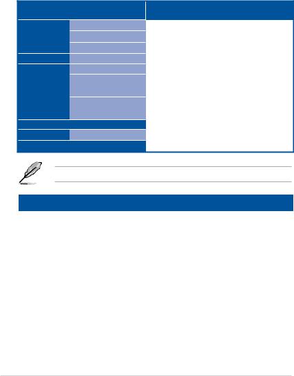
Z10PE-D16 WS specifications summary
|
Dual Intel® Socket 2011-3 for Xeon® processor E5-2600 v3 /v4 |
|||
|
CPU |
product family |
||
|
QPI 6.4 / 8.0 / 9.6 GT/s |
|||
|
* Refer to www.asus.com for CPU support list |
|||
|
Chipset |
Intel® C612 PCH |
||
|
DDR4 16 x DIMM (4-channel per CPU, 8 DIMM per CPU), Max. |
|||
|
1024GB |
|||
|
DDR4 2400* / 2133* / 1866 / 1600 MHz RDIMM / LR-DIMM* |
|||
|
Quad channel memory architecture |
|||
|
* Actual memory frequency differs from Intel CPU types and memory |
|||
|
Memory |
modules. |
||
|
When installing E5-2600 v3 CPUs: |
|||
|
— RDIMM: 2133MT/s is supported at 1 DPC only |
|||
|
— LR-DIMM: 2133MT/s is supported |
|||
|
When installing E5-2600 v4 CPUs: |
|||
|
— RDIMM: 2400MT/s is supported at 1 DPC only |
|||
|
— LR-DIMM: 2400MT/s is supported |
|||
|
** Refer to www.asus.com for the memory QVL (Qualified Vendors Lists). |
|||
|
Slot 1: PCIE x16 (x8 Gen3 Link) |
|||
|
Slot 2: PCIE X16 (x16 Gen3 Link) |
|||
|
Slot 3: PCIE x16 (x8 Gen3 Link) |
|||
|
Slot 4: PCIE X16 (x16 Gen3 Link) |
|||
|
Expansion slots |
Slot 5: PCIE x16 (x16 Gen3 Link) |
||
|
Slot 6: PCIE x16 (x16 Gen3 Link) |
|||
|
* This motherboard is ready to support PCIe 3.0 specification. Functions |
|||
|
will be available when using PCIe 3.0-compliant devices. Refer to |
|||
|
www.asus.com for the latest updates and information. |
|||
|
ASpeed AST2400 32MB |
|||
|
VGA Output |
VGA port (with bracket) |
||
|
Supports VGA with max. resolution 1920 x 1200 at 60Hz |
|||
|
Multi-GPU support |
Supports NVIDIA® 3-Way SLI™ Technology |
||
|
Supports AMD® Quad-GPU CrossFireX™ Technology |
|||
|
Intel® C612 Chipset: |
|||
|
10 x SATA 6Gb/s ports (6 x right angle connectors from SATA |
|||
|
controller, 4 x vertical connectors from sSATA controller)* with Intel® |
|||
|
RSTe RAID 0, 1, 5 and 10 support (for Windows only) |
|||
|
Storage |
1 x Discrete M.2 Socket 3* |
||
|
LSI MegaRAID driver supports software RAID 0, 1 and 10 (Windows |
|||
|
& Linux)** |
|||
|
* M.2 Socket 3 supports M Key and type 2260/2280/22110 storage devices, |
|||
|
and M.2 share bandwidth with SSATA Port 4. |
|||
|
** LSI MegaRAID only supports SATA Controller. |
|||
|
LAN |
2 x Intel® I210AT Gigabit LAN controller |
||
|
1 x Management Port |
|||
|
(continues on next page) |
xi

Z10PE-D16 WS specifications summary
|
Realtek® ALC1150 8-channel high definition audio CODEC |
||
|
— High quality 112dB SNR stereo playback output (Line-out at rear) |
||
|
and 104dB SNR recording input (Line-in) support. |
||
|
— Absolute Pitch 192khz/24bit True BD Lossless Sound |
||
|
Audio |
— BD audio layer content protection |
|
|
— DTS UltraPC II |
||
|
— DTS Connect |
||
|
— Supports jack-detection, multi-streaming and front panel jack- |
||
|
retasking |
||
|
— Optical S/PDIF out ports at rear I/O |
|
Intel®C612 Chipset |
|||
|
USB |
— 6 x USB 3.0/2.0 ports (2 ports at mid-board, 4 ports at back panel) |
||
|
— 6 x USB 2.0/1.1 ports (2 ports at mid-board, 4 ports at back panel) |
|||
|
CPU Power |
|||
|
— Digital 7 Phase Power Design |
|||
|
DRAM Power |
|||
|
— Digital 2 Phase Power Design |
|||
|
ASUS Exclusive Features |
|||
|
— Front Panel USB 3.0 Support |
|||
|
Key Selling Points |
ASUS Quiet Thermal Solution |
||
|
— ASUS Fanless Design: Heat pipe solution |
|||
|
ASUS EZ DIY |
|||
|
— ASUS CrashFree BIOS 3 |
|||
|
— ASUS EzFlash Utility |
|||
|
— ASUS MyLogo 2 |
|||
|
— Multi-language BIOS |
|||
|
— 6 PCIe x 16 slots |
|||
|
— 12K hours Capacitors |
|||
|
— ProCool Power Connector |
|||
|
Workstation Unique |
— ASUS Dr. Power |
||
|
— Q-Code Logger |
|||
|
Features |
|||
|
— USB BIOS Flashback |
|||
|
— ASWM Enterprise |
|||
|
— ASUS PIKE SAS upgrade kit (Optional) |
|||
|
— ASMB8-iKVM Remote Management Tool |
|||
|
(continues on next page) |
xii

Z10PE-D16 WS specifications summary
|
4 x USB 3.0/2.0 ports (blue) |
||
|
4 x USB 2.0/1.1 ports (1 supports USB BIOS Flashback, 1 supports |
||
|
Q-Code Logger) |
||
|
1 x USB BIOS Flashback button |
||
|
Back Panel I/O Ports |
1 x Q-Code Logger button |
|
|
1 x PS/2 KB port |
||
|
2 x LAN (RJ45) ports (2 x Intel® LAN) |
||
|
1 x Management Port |
||
|
1 x Optical S/PDIF Out port |
||
|
8-channel Audio I/O |
||
|
1 x USB 3.0/2.0 connector support additional 2 USB ports (19-pin) |
||
|
1 x USB 2.0/1/1 connectors support additional 2 USB ports |
||
|
1 x M.2 Socket 3 |
||
|
10 x SATA 6.0Gb/s connectors |
||
|
2 x CPU Fan connector (4-pin) |
||
|
7 x Chassis Fan connectors (4-pin) |
||
|
1 x Serial Port header |
||
|
1 x RAID key header |
||
|
1 x VGA connector |
||
|
1 x Front panel audio connector(AAFP) |
||
|
Internal I/O Connectors |
1 x AUX panel header |
|
|
1 x System Panel header |
||
|
1 x SMBus headers |
||
|
1 x S/PDIF Out header |
||
|
1 x Clear CMOS header |
||
|
1 x TPM connector |
||
|
1 x 24-pin EATX Power connector |
||
|
2 x 8-pin EATX 12V Power connectors |
||
|
1 x ASUS Dr.Power switch |
||
|
1 x System Panel |
||
|
1 x PWR button |
||
|
1 x Reset button |
||
|
BIOS Features |
128 Mb Flash ROM, UEFI BIOS, PnP, WfM2.0, SMBIOS 2.6.1, ACPI |
|
|
3.0, ASUS EZ Flash Utility, ASUS CrashFree Technology |
||
|
Manageability |
WfM 2.0, DMI 2.0, WOL by PME, PXE |
|
|
Drivers |
||
|
Support DVD |
ASUS Utilities |
|
|
ASUS Update |
||
|
Form Factors |
EEB Form Factor, 12 in. x 13 in. |
|
* Refer to ASUS Server AVL for latest update.
Specifications are subject to change without notice.
xiii

xiv
This chapter describes the motherboard features and the new technologies it supports.
1.1Welcome!
Thank you for buying an ASUS® Z10PE-D16 WS motherboard!
The motherboard delivers a host of new features and latest technologies, making it another standout in the long line of ASUS quality motherboards!
Before you start installing the motherboard, and hardware devices on it, check the items in your package with the list below.
1.2Package contents
Check your motherboard package for the following items.
|
VGA cable with bracket |
|
|
Cables |
SATA 6G cable |
|
COM port cable |
|
|
I/O Modules |
2-port USB 2.0 |
|
I/O shield |
|
|
2-Way SLI Bridge |
|
|
Accessories |
connector |
|
3-Way SLI Bridge |
|
|
connector |
ASWM Enterprise SDVD
Application CD Support CD
Packaging Qty.
|
Standard Gift Box |
Standard Bulk Pack |
|
|
Pack |
||
|
1 |
— |
|
|
10 |
— |
|
|
1 |
— |
|
|
1 |
— |
|
|
1 |
1 |
|
|
1 |
— |
|
|
1 |
— |
|
|
1 |
1 piece per carton |
|
|
1 |
1 piece per carton |
|
|
1 piece per carton |
5 pcs per carton |
If any of the above items is damaged or missing, contact your retailer.
|
Optional items |
Description |
|
|
PIKE II 3008 |
LSI 8-port SAS 12G |
RAID card |
|
PIKE II 3108 |
LSI 8-port SAS 12G |
HW RAID card |
|
PEB-10G/57840-2S |
Dual port 10G SFP+ Ethernet Adapter |
|
|
PEB-10G/57811-1S |
Single port 10G SFP+ Ethernet |
|
1-2 |
Chapter 1: Product Introduction |

1.3Serial number label
Before requesting support from the ASUS Technical Support team, you must take note of the motherboard’s serial number containing 12 characters xxS1xxxxxxxx shown as the figure below. With the correct serial number of the product, ASUS Technical Support team members can then offer a quicker and satisfying solution to your problems.
|
Z10PE-D16 WS |
Made |
|
in |
|
|
Taiwan |
|
|
xxS1xxxxxxxx |
|
1.4Special features
1.4.1Product highlights
Latest Processor Technology
The motherboard supports Intel Xeon® processor E5-2600 V3 product family which provides compelling IPC increases for legacy performance improvements, floating point improvement, easier multi-core programming, and with next-generation processor power management.
Intel ® Xeon processor E5-2600 v3 product family also improve the I/O capabilities and support QPI link speed of up to 9.6GT/s.
Intel® AVX 2.0
Intel® AVX 2.0 extends 256-bit vector support for integer vector operations, doubles fixed point arithmetic throughput, adds support for new vector gather, permutes/blend, vector shifts resulting in fixed and floating-point algorithm improvements. Also, Intel’s new microarchitecture doubles the cache bandwidth at L1/L2 to support higher FLOPS and contributes to greater performance in signal and image processing applications.
Next Generation of processor power management
Intel ® Xeon processor E5-2600 v3 product family enhances the processor power management with the features of Energy Efficient Turbo, Uncore Frequency Scaling, and
Per-Core P-state. Also, the Integrated Voltage Regulator enables generational performance and power improvements that the standard VR solutions cannot provide.
DDR4 memory support
The motherboard supports DDR4 memory that features faster clock frequencies and higher data transfer rates of 1600 MT/s to 2133 MT/s (million transfers per second). DDR4 offers a lower voltage standard of 1.2V that reduces memory power demand and provides improved performance.

PCI Express 3.0
PCI Express 3.0 (PCIe 3.0) is the PCI Express bus standard that provides twice the performance and speed of PCIe 2.0. It provides optimal graphics performance,
unprecedented data speed, and seamless transition with its complete backward compatibility to PCIe 2.0 devices.
M.2 Support
This motherboard features the M.2 slot which shares bandwidth with the SATA 6Gb/s port and PCI-E Gen2 x2 and is dedicated only to the operating system.
Intel® C612 Series Chipset
The Intel® C612 series chipset has enterprise class features targeted for Cloud and Storage applications. It is optimized and validated to work with the latest Xeon® processor E5-2600 v3 product family. It reduces the TDP and supports USB 3.0 and SATA III ports thus bringing more features and benefits to target users.
Intel® I210AT LAN Solution
The motherboard comes with two Gigabit LAN controllers and ports which provide a total solution for your networking needs. The onboard Intel® I210AT Gigabit LAN controllers use the PCI Express interface and could achieve network throughput close to Gigabit bandwidth.
Serial ATA III technology
The motherboard supports the Serial ATA III technology through the Serial ATA interface and Intel® C612 chipset, delivering up to 6 Gb/s data transfer rates. It also provides enhanced scalability, faster data retrieval, and double the bandwidth of current bus systems.
Temperature, fan, and voltage monitoring
The CPU temperature is monitored to prevent overheating and damage. The system fan rotations per minute (RPM) is monitored for timely failure detection. The chip monitors the voltage levels to ensure a stable supply of current for critical components.
|
1-4 |
Chapter 1: Product Introduction |
1.4.2Innovative ASUS features
ASUS Fan Speed control technology
The ASUS Fan Speed control technology smartly adjusts the fan speeds according to the system loading to ensure quiet, cool, and efficient operation.
Support 3-Way NVIDIA® GeForce® SLI™ and Quad-GPU AMD® CrossFireX™
Native third generation PCI-Express x16 support 3-Way NVIDIA® GeForce® SLI™ and QuadGPU AMD® CrossFireX™ offers the fastest and most reliable graphics performance ever. It’s ideal for professional use in mechanical, architectural, interior design, aeronautics, audio and video design applications. Additionally, this ample graphics power can easily run even the most demanding PC games in full detail for enhanced entertainment.
Q-Code Logger
Q-Code Logger is your one-touch troubleshooter that lets you easily check Q-Code event logs without opening the computer’s case. If a workstation is behaving abnormally, plug a flash drive into the adjacent USB port, press the motherboard’s dedicated Flash log button and ASUS Q-Code event logs for the current live session wil be copied into the drive.
ProCool Connector
ProCool eliminates the hollow areas associated with traditional power connectors, ensuring and exceptionally close and secure connection with this motherboard. This design is much stronger, and provides better heat dissipation, allowing cooler operating temperatures.
ASUS Dr. Power
ASUS Dr. Power detects any relevant power issues to prevent sudden system shutdown and provides hassle-free notifications when power delivery is not sufficient.
USB Charger+
USB Charger+ allows you to quick-charge your portable USB devices* even if your computer is off, in sleep mode or hibernate mode.
* Actual charging speeds may vary depending on the charging rate and specifications of your USB device.
•To ensure normal charging function, disconnect and reconnect your USB device every time you enable or disable USB Charger+.
• USB Charger+ does not support USB hubs, USB extension cables, and generic USB cables.

|
1-6 |
Chapter 1: Product Introduction |
This chapter lists the hardware setup procedures that you have to perform when installing system components. It includes description of the jumpers and connectors on the motherboard.

2.1Before you proceed
Take note of the following precautions before you install motherboard components or change any motherboard settings.
• Unplug the power cord from the wall socket before touching any component.
•Use a grounded wrist strap or touch a safely grounded object or a metal object, such as the power supply case, before handling components to avoid damaging them due to static electricity.
•Hold components by the edges to avoid touching the ICs on them.
•Whenever you uninstall any component, place it on a grounded antistatic pad or in the bag that came with the component.
•Before you install or remove any component, ensure that the power supply is switched off or the power cord is detached from the power supply. Failure to do so may cause severe damage to the motherboard, peripherals, and/or components.
|
2-2 |
Chapter 2: Hardware Information |
2.2Motherboard overview
Before you install the motherboard, study the configuration of your chassis to ensure that the motherboard fits into it.
To optimize the motherboard features, we highly recommend that you install it in an EEB compliant chassis.
Ensure to unplug the chassis power cord before installing or removing the motherboard.
Failure to do so can cause you physical injury and damage motherboard components!
2.2.1Placement direction
When installing the motherboard, ensure that you place it into the chassis in the correct orientation. The edge with external ports goes to the rear part of the chassis as indicated in the image below.
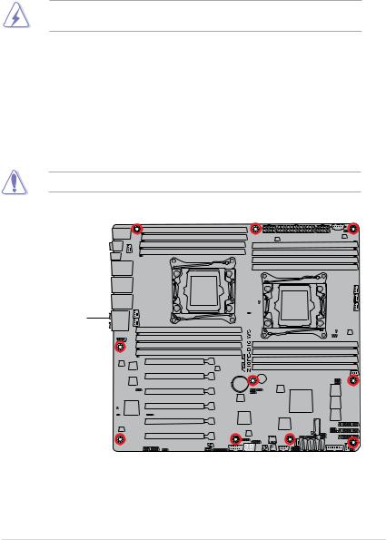
2.2.2Screw holes
Place ten (10) screws into the holes indicated by circles to secure the motherboard to the chassis.
DO NOT over tighten the screws! Doing so can damage the motherboard.
Place this side towards the rear of the chassis
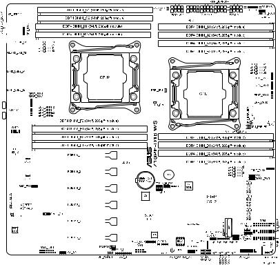
2.2.3Z10PE-D16 WS Motherboard layout
|
2-4 |
Chapter 2: Hardware Information |

2.2.4Layout contents
|
Slots/Socket |
Page |
|
|
1. |
CPU sockets |
2-7 |
|
2. |
DDR4 sockets |
2-12 |
|
3. |
PCI Express x16 slots |
2-16 |
|
Onboard buttons and switches |
Page |
|
|
1. |
Power-on button |
2-18 |
|
2. |
Reset button |
2-18 |
|
3. |
Dr. Power switch (DR_POWER) |
2-19 |
|
Onboard LEDs |
Page |
1.Memory Error LED (ERR_DIMMA1, ERR_DIMMB1, ERR_DIMMC1,
|
ERR_DIMMD1, ERR_DIMME1, ERR_DIMMF1, ERR_DIMMG1, |
2-20 |
||
|
ERR_DIMMH1) |
|||
|
2. |
Baseboard Management Controller LED (BMC_LED1) |
2-20 |
|
|
3. |
Location LED (LOCLED2) |
2-21 |
|
|
4. |
CATT LED (CATTERR_LED1) |
2-21 |
|
|
5. |
CPU Warning LED (ERR_CPU1, ERR_CPU2) |
2-22 |
|
|
6. |
M2 LED (M2_LED) |
2-22 |
|
|
7. |
ASUS Dr. Power LED (PGLED3) |
2-23 |
|
|
8. |
Q-Code LED (LED1) |
2-24 |
|
|
Jumpers |
Page |
||
|
1. |
Clear RTC RAM (CLRTC1) |
2-28 |
|
|
2. |
VGA controller setting (VGA_SW1) |
2-29 |
|
|
3. |
SMBUS connection setting (TESLA_M_SW) |
2-29 |
|
|
4. |
RAID selection jumper setting (3-pin RAID_SEL1) |
2-30 |
|
|
5. |
ME firmware force recovery setting (3-pin ME_RCVR1) |
2-30 |
|
|
6. |
DDR4 thermal event setting (3-pin DIMMTRIP1) |
2-31 |
|
|
7. |
PMBus 1.2 PSU select jumper (3-pin SMART_PSU1) |
2-31 |
|
|
8. |
BMC Setting (3-pin BMC_EN1) |
2-32 |

|
Rear panel connectors |
Page |
|
|
1. |
PS/2 mouse and keyboard port |
2-33 |
|
2. |
Q-Code Logger button |
2-33 |
|
3. |
Optical S/PDIF Out port |
2-33 |
|
4. |
LAN 3 port |
2-33 |
|
5. |
LAN 2 port |
2-33 |
|
6. |
LAN 1 port (RJ-45 port for LAN1 and BMC share) |
2-33 |
|
7. |
8-channel Audio I/O |
2-33 |
|
8. |
USB 2.0 ports 9 and 10 |
2-33 |
|
9. |
USB BIOS Flashback button |
2-33 |
|
10. |
USB 2.0 ports 7 and 8 |
2-33 |
|
11. |
USB 3.0 ports 3 and 4 |
2-33 |
|
12. |
USB 3.0 ports 1 and 2 |
2-33 |
|
Internal connectors |
Page |
|
|
1. |
Hard disk activity LED connector (4-pin HDLED1) |
2-36 |
|
2. |
USB 2.0 connectors (10-1 pin USB1112) |
2-36 |
|
3. |
USB 3.0 connector (20-1 pin USB3_56) |
2-37 |
|
4. |
CPU, front and rear fan connectors (4-pin CPU_FAN1-2, |
2-37 |
|
FRNT_FAN1-5, REAR_FAN1-2) |
||
|
5. |
Power supply SMBus Connector (PSUSMB1) |
2-38 |
|
6. |
Serial port connectors (10-1 pin COM1) |
2-38 |
|
7. |
Serial ATA 6.0/3.0 Gb/s connectors (7-pin SATA_1-6 [gray]) |
2-39 |
|
Serial ATA 6.0/3.0 Gb/s connectors (7-pin SSATA_1-4 [gray]) |
||
|
8. |
Serial General Purpose Input/Output connector (6-1 pin SGPIO1, |
2-40 |
|
SSGPIO1) |
||
|
9. |
M.2 (NGFF) connector (NGFF1) |
2-40 |
|
10. |
Trusted Platform Module connector (20-1 pin TPM1) |
2-41 |
|
11. |
EATX power connectors (24-pin EATXPWR1; 8-pin EATX12V1/ |
2-41 |
|
EATX12V2; 6-pin EATX12V3) |
||
|
12. |
Chassis Intrusion (2-pin INTRUSION1) |
2-42 |
|
13. |
System panel connector (20-1 pin PANEL1) |
2-43 |
|
14. |
Auxiliary panel connector (20-2 pin AUX_PANEL1) |
2-44 |
|
15. |
Digital audio connector (4-1 pin SPDIF_OUT) |
2-45 |
|
16. |
VGA connector (VGA_HDR1) |
2-46 |
|
17. |
Front panel audio connector (10-1 pin AAFP) |
2-46 |
|
2-6 |
Chapter 2: Hardware Information |
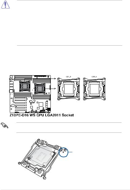
2.3Central Processing Unit (CPU)
The motherboard comes with a surface mount LGA 2011-3 socket designed for the Intel® Xeon E5-2600 V3 family processor.
•Upon purchase of the motherboard, ensure that the PnP cap is on the socket and
the socket contacts are not bent. Contact your retailer immediately if the PnP cap is missing, or if you see any damage to the PnP cap/socket contacts/motherboard components. ASUS will shoulder the cost of repair only if the damage is shipment/ transit-related.
•Keep the cap after installing the motherboard. ASUS will process Return Merchandise Authorization (RMA) requests only if the motherboard comes with the cap on the LGA
2011-3 socket.
•The product warranty does not cover damage to the socket contacts resulting from incorrect CPU installation/removal, or misplacement/loss/incorrect removal of the PnP cap.
2.3.1Installing the CPU
To install a CPU:
1.Locate the CPU socket on the motherboard.
Before installing the CPU, ensure that the socket box is facing toward you and the triangle mark is on the top-right position.
Triangle mark
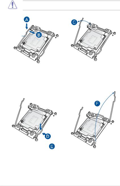
2.Press the left load lever down with your thumb (A), move it to the right until it is released from the retention tab (B) then gently lift the load lever (C).
To prevent damage to the socket pins, do not remove the PnP cap unless you are installing a CPU.
Load
3.Press the right load lever with your thumb (D), move it to the left until it is released from then gently lift the load lever (F).
|
2-8 |
Chapter 2: Hardware Information |
4.Push the left load lever to slightly lift the load plate (G).
Do not insert the load lever into the retention tab.
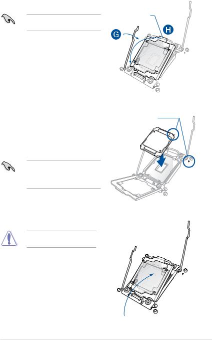
5.Hold the edge then gently lift the load plate (H).
6.Get the CPU.
7.Align and position the CPU over the socket ensuring that the triangle mark on the CPU matches the triangle mark on the socket box.
8.Install the CPU into the slot.
The CPU fits in only one correct orientation. DO NOT force the CPU into the socket to prevent bending the
CPU pins on the socket.
9.Gently push the load plate just enough to let it sit on top of the CPU.
Do not force to close the load plate as it may damage the CPU.
edge of the Load plate
 Load plate
Triangle mark
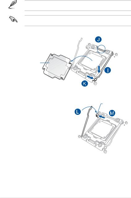
10.Push down the right load lever (I) ensuring that the edge of the load plate is fixed and tucked securely under the lever (J) then insert the right load lever under the retention tab (K).
The PnP cap pops out of the load plate when the right load lever is inserted into the retention tab.
Keep the PnP cap. ASUS will process Return Merchandise Authorization (RMA) requests only if the motherboard comes with the PnP cap on the LGA 2011 socket.
PnP cap
11.Push down the left load lever (L) then insert it under the retention tab (M).
Retention tab
|
2-10 |
Chapter 2: Hardware Information |
![]()
12.Apply some Thermal Interface Material to the exposed area of the CPU that the
heatsink will be in contact with.
• Ensure that the Thermal Interface Material is spread in an even thin layer.
• Some heatsinks come with pre-applied Thermal Interface
Material. If so, skip this step.
The Thermal Interface Material is toxic and inedible. DO NOT eat it. If it gets into your eyes or touches your skin, wash it off immediately, and seek professional medical help.
13.Connect the CPU fan cable to the connector on the motherboard labeled CPU_FAN1 / CPU_FAN2.
DO NOT forget to connect the CPU fan connector! Hardware monitoring errors can occur if you fail to plug this connector.

2.4System memory
2.4.1Overview
The motherboard comes with sixteen (16) Double Data Rate 4 (DDR4) Dual Inline Memory Modules (DIMM) sockets.
The figure illustrates the location of the DDR4 DIMM sockets:
2.4.2Memory Configurations
You may install 4 GB, 8 GB, 16 GB, and 32 GB RDIMMs or 32 GB and 64 GB LR-DIMMs into the DIMM sockets using the memory configurations in this section.
•Refer to ASUS Server AVL for the updated list of compatible DIMMs.
•When installing DIMMs, always start from slot A1 (CPU1) and E1 (CPU2).
•Always install DIMMs with the same CAS latency. For optimum compatibility, it is recommended that you obtain memory modules from the same vendor.
|
2-12 |
Chapter 2: Hardware Information |

Single CPU configuration
You can refer to the following recommended memory population for a single CPU configuration.
Single CPU configuration (must be installed on CPU1)
|
DIMM |
|||||||||
|
A2 |
A1 |
B2 |
B1 |
C2 |
C1 |
D2 |
D1 |
||
|
1 DIMM |
P |
||||||||
|
2 DIMMs |
P |
P |
|||||||
|
4 DIMMs |
P |
P |
P |
P |
|||||
|
8 DIMMs |
P |
P |
P |
P |
P |
P |
P |
P |
Dual CPU configuration
You can refer to the following recommended memory population for a dual CPU configuration.
Dual CPU configuration
|
DIMM (CPU1) |
DIMM (CPU2) |
|||||||||||||||||||
|
A2 |
A1 |
B2 |
B1 |
C2 |
C1 |
D2 |
D1 |
E2 |
E1 |
F2 |
F1 |
G2 |
G1 |
H2 |
H1 |
|||||
|
2 DIMMs |
P |
P |
||||||||||||||||||
|
4 DIMMs |
P |
P |
P |
P |
||||||||||||||||
|
8 DIMMs |
P |
P |
P |
P |
P |
P |
P |
P |
||||||||||||
|
12 DIMMs |
P |
P |
P |
P |
P |
P |
P |
P |
P |
P |
P |
P |
||||||||
|
16 DIMMs |
P |
P |
P |
P |
P |
P |
P |
P |
P |
P |
P |
P |
P |
P |
P |
P |

2.4.3Installing a DIMM on a single clip DIMM socket
|
1. |
Press the retaining clip outward to |
DIMM notch |
|
unlock the DIMM socket. |
||
|
2. |
Align a DIMM on the socket such that |
|
|
the notch on the DIMM matches the |
||
|
DIMM slot key on the socket. |
|
DIMM slot key |
Unlocked retaining clip |
A DIMM is keyed with a notch so that it fits in only one direction. DO NOT force a DIMM into a socket in the wrong direction to avoid damaging the DIMM.
3.Hold the DIMM at both ends then insert the DIMM into the socket. Apply force to
both ends of the DIMM simultaneously until the retaining clip clicks into place and the DIMM is seated securely in place.
Locked Retaining Clip
Always insert the DIMM into the socket VERTICALLY to prevent DIMM notch damage.
•To install two or more DIMMs, refer to the user guide bundled with the motherboard
package.
•Refer to the user guide for qualified vendor lists of the memory modules.
Removing a DIMM from a single clip DIMM socket
1.Press the retaining clip outward to unlock the DIMM.
2. Remove the DIMM from the socket.
Support the DIMM lightly with your fingers when pressing the retaining clips. The DIMM might get damaged when it flips out with extra force.
|
2-14 |
Chapter 2: Hardware Information |

2.5Expansion slots
In the future, you may need to install expansion cards. The following subsections describe the slots and the expansion cards that they support.
Ensure to unplug the power cord before adding or removing expansion cards. Failure to do so may cause you physical injury and damage motherboard components.
2.5.1Installing an expansion card
To install an expansion card:
1.Before installing the expansion card, read the documentation that came with it and make the necessary hardware settings for the card.
2.Remove the system unit cover (if your motherboard is already installed in a chassis).
3.Remove the bracket opposite the slot that you intend to use. Keep the screw for later use.
4.Align the card connector with the slot and press firmly until the card is completely seated on the slot.
5.Secure the card to the chassis with the screw you removed earlier.
6.Replace the system cover.
2.5.2Configuring an expansion card
After installing the expansion card, configure it by adjusting the software settings.
1.Turn on the system and change the necessary BIOS settings, if any. See Chapter 4 for information on BIOS setup.
2.Assign an IRQ to the card.
Refer to the table Standard Interrupt assignments in section Interrupt assignments for more information.
3.Install the software drivers for the expansion card.
When using PCI cards on shared slots, ensure that the drivers support “Share IRQ” or that the cards do not need IRQ assignments. Otherwise, conflicts may arise between the two PCI groups, making the system unstable and the card inoperable.

2.5.3Interrupt assignments
Standard Interrupt assignments
|
IRQ |
Priority Standard function |
01 System Timer
12 Keyboard Controller
2— Programmable Interrupt
|
3* |
11 |
Communications Port (COM2) |
|
4* |
12 |
Communications Port (COM1) |
|
5* |
13 |
— |
|
6 |
14 |
Floppy Disk Controller |
|
7* |
15 |
— |
|
8 |
3 |
System CMOS/Real Time Clock |
|
9* |
4 |
ACPI Mode when used |
|
10* |
5 |
IRQ Holder for PCI Steering |
|
11* |
6 |
IRQ Holder for PCI Steering |
|
12* |
7 |
PS/2 Compatible Mouse Port |
|
13 |
8 |
Numeric Data Processor |
|
14* |
9 |
Primary IDE Channel |
|
15* |
10 |
Secondary IDE Channel |
* These IRQs are usually available for ISA or PCI devices.
2.5.4PCI Express x16 slot (x16 link)
The on board PCIE 2 and 4 provide one x16 Gen3 link to CPU1, PCIE 5 and 6 provide one x16 Gen3 link to CPU2. These slots support VGA cards and various server class high performance add-on cards.
2.5.5PCI Express x16 slot (x8 link)
The onboard PCIE 1 provide one x8 Gen3 link to CPU2 and PCIE 3 provide one x8 Gen3 link to CPU1. These slot support VGA Cards and various server class high performance add-on cards.
|
2-16 |
Chapter 2: Hardware Information |

Motherboard Layout
PCIE 1 1 x PCIE x16 (x8 Gen3 Link) PCIE 2 1 x PCIE X16 (x16 Gen3 Link) PCIE 3 1 x PCIE x16 (x8 Gen3 Link) PCIE 4 1 x PCIE X16 (x16 Gen3 Link) PCIE 5 1 x PCIE x16 (x16 Gen3 Link) PCIE 6 1x PCIE x16 (x16 Gen3 Link)

2.6Onboard buttons and switches
Onboard switches allow you to fine-tune performance when working on a bare or opencase system. This is ideal for overclockers and gamers who continually change settings to enhance system performance.
1.Power-on
The motherboard comes with a power-on switch that allows you to power up or wake up the system. The switch also lights up when the system is plugged to a power source indicating that you should shut down the system and unplug the power cable before removing or plugging in any motherboard component. The illustration below shows the location of the onboard power-on switch.
2.Reset button (RESET)
Press the reset switch to reboot the system.
|
2-18 |
Chapter 2: Hardware Information |

3.Dr. Power switch (DR_POWER)
Toggle this switch to enable or disable the Dr. Power feature of the system.

2.7Onboard LEDs
1.Memory Error LED (ERR_DIMMA1, ERR_DIMMB1, ERR_DIMMC1, ERR_DIMMD1, ERR_DIMME1, ERR_DIMMF1, ERR_DIMMG1, ERR_DIMMH1)
These LEDs light up to indicate an error in its nearby DIMM.
2.Baseboard Management Controller LED (BMC_LED1)
The BMC LED works with the ASUS ASMB8 management device and indicates its initiation status. When the PSU is plugged and the system is OFF, ASUS ASMB8 management device starts system initiation for about one (1) minute. The BMC LED blinks after system initiation finishes.
|
2-20 |
Chapter 2: Hardware Information |
![]()
3.Location LED (LOCLED2)
This onboard LED lights up when the Location button on the server is pressed or when triggered by a system management software. The Location LED helps visually locate and quickly identify the server in error on a server rack.
4.CATT LED (CATTERR_LED1)
The CATT LED indicates that the system has experienced a fatal or catastrophic error and cannot continue to operate.

5.CPU Warning LED (ERR_CPU1, ERR_CPU2)
The CPU warning LEDs light up to indicate failure on either CPU1, CPU2, or both.
6.M2 LED (M2_LED)
This LED lights up to indicate that the installed M.2 (NGFF) card is being accessed.
|
2-22 |
Chapter 2: Hardware Information |

7.ASUS Dr. Power LED (PGLED3)
This LED near the Dr. Power switch lights up when the Dr. Power switch is on Enable.

8.Q-Code LED (LED1)
TheQ-CodeLEDdesignprovidesyouthe2-digitdisplay,allowingyoutoknowthesystem
status. Refer to the Q-code table below for details.
Q-Code table
|
Code |
Description |
|
|
00 |
Not used |
|
|
01 |
Power on. Reset type detection (soft/hard). |
|
|
02 |
AP initialization before microcode loading |
|
|
03 |
System Agent initialization before microcode loading |
|
|
04 |
PCH initialization before microcode loading |
|
|
06 |
Microcode loading |
|
|
07 |
AP initialization after microcode loading |
|
|
08 |
System Agent initialization after microcode loading |
|
|
09 |
PCH initialization after microcode loading |
|
|
0A |
Initialization after microcode loading |
|
|
0B |
Cache initialization |
|
|
0C – 0D |
Reserved for future AMI SEC error codes |
|
|
0E |
Microcode not found |
|
|
0F |
Microcode not loaded |
|
|
10 |
PEI Core is started |
|
|
11 |
– 14 |
Pre-memory CPU initialization is started |
|
15 |
– 18 |
Pre-memory System Agent initialization is started |
|
19 |
– 1C |
Pre-memory PCH initialization is started |
|
2B – 2F |
Memory initialization |
|
|
30 |
Reserved for ASL (see ASL Status Codes section below) |
|
2-24 |
Chapter 2: Hardware Information |

Q-Code table (continued)
|
Code |
Description |
|||
|
31 |
Memory Installed |
|||
|
32 |
– 36 |
CPU post-memory initialization |
||
|
37 |
– 3A |
Post-Memory System Agent initialization is started |
||
|
3B – 3E |
Post-Memory PCH initialization is started |
|||
|
4F |
DXE IPL is started |
|||
|
50 |
– 53 |
Memory initialization error. Invalid memory type or incompatible memory |
||
|
speed |
||||
54Unspecified memory initialization error
55Memory not installed
56Invalid CPU type or Speed
57CPU mismatch
58CPU self test failed or possible CPU cache error
59CPU micro-code is not found or micro-code update is failed
|
5A |
Internal CPU error |
|
5B |
Reset PPI is not available |
|
5C – 5F |
Reserved for future AMI error codes |
|
E0 |
S3 Resume is stared (S3 Resume PPI is called by the DXE IPL) |
|
E1 |
S3 Boot Script execution |
|
E2 |
Video repost |
|
E3 |
OS S3 wake vector call |
|
E4 – E7 |
Reserved for future AMI progress codes |
|
E8 |
S3 Resume Failed |
|
E9 |
S3 Resume PPI not Found |
|
EA |
S3 Resume Boot Script Error |
|
EB |
S3 OS Wake Error |
|
EC – EF |
Reserved for future AMI error codes |
|
F0 |
Recovery condition triggered by firmware (Auto recovery) |
|
F1 |
Recovery condition triggered by user (Forced recovery) |
|
F2 |
Recovery process started |
|
F3 |
Recovery firmware image is found |
|
F4 |
Recovery firmware image is loaded |
|
F5 – F7 |
Reserved for future AMI progress codes |
|
F8 |
Recovery PPI is not available |
|
F9 |
Recovery capsule is not found |
|
FA |
Invalid recovery capsule |
|
FB – FF |
Reserved for future AMI error codes |
60DXE Core is started
61NVRAM initialization
62Installation of the PCH Runtime Services

Q-Code table (continued)
|
Code |
Description |
|
63 – 67 |
CPU DXE initialization is started |
68PCI host bridge initialization
69System Agent DXE initialization is started
|
6A |
System Agent DXE SMM initialization is started |
|
6B – 6F |
System Agent DXE initialization (System Agent module specific) |
70PCH DXE initialization is started
71PCH DXE SMM initialization is started
72PCH devices initialization
73– 77 PCH DXE Initialization (PCH module specific)
78ACPI module initialization
79CSM initialization
7A – 7F Reserved for future AMI DXE codes
90Boot Device Selection (BDS) phase is started
91Driver connecting is started
92PCI Bus initialization is started
93PCI Bus Hot Plug Controller Initialization
94PCI Bus Enumeration
95PCI Bus Request Resources
96PCI Bus Assign Resources
97Console Output devices connect
98Console input devices connect
99Super IO Initialization
|
9A |
USB initialization is started |
|
9B |
USB Reset |
|
9C |
USB Detect |
|
9D |
USB Enable |
|
9E – 9F |
Reserved for future AMI codes |
|
A0 |
IDE initialization is started |
|
A1 |
IDE Reset |
|
A2 |
IDE Detect |
|
A3 |
IDE Enable |
|
A4 |
SCSI initialization is started |
|
A5 |
SCSI Reset |
|
A6 |
SCSI Detect |
|
A7 |
SCSI Enable |
|
A8 |
Setup Verifying Password |
|
A9 |
Start of Setup |
|
AA |
Reserved for ASL (see ASL Status Codes section below) |
|
AB |
Setup Input Wait |
|
2-26 |
Chapter 2: Hardware Information |

Q-Code table (continued)
|
Code |
Description |
|
|
AC |
Reserved for ASL (see ASL Status Codes section below) |
|
|
AD |
Ready To Boot event |
|
|
AE |
Legacy Boot event |
|
|
AF |
Exit Boot Services event |
|
|
B0 |
Runtime Set Virtual Address MAP Begin |
|
|
B1 |
Runtime Set Virtual Address MAP End |
|
|
B2 |
Legacy Option ROM Initialization |
|
|
B3 |
System Reset |
|
|
B4 |
USB hot plug |
|
|
B5 |
PCI bus hot plug |
|
|
B6 |
Clean-up of NVRAM |
|
|
B7 |
Configuration Reset (reset of NVRAM settings) |
|
|
B8– BF |
Reserved for future AMI codes |
|
|
D0 |
CPU initialization error |
|
|
D1 |
System Agent initialization error |
|
|
D2 |
PCH initialization error |
|
|
D3 |
Some of the Architectural Protocols are not available |
|
|
D4 |
PCI resource allocation error. Out of Resources |
|
|
D5 |
No Space for Legacy Option ROM |
|
|
D6 |
No Console Output Devices are found |
|
|
D7 |
No Console Input Devices are found |
|
|
D8 |
Invalid password |
|
|
D9 |
Error loading Boot Option (LoadImage returned error) |
|
|
DA |
Boot Option is failed (StartImage returned error) |
|
|
DB |
Flash update is failed |
|
|
DC |
Reset protocol is not available |
|
|
ACPI/ASL Checkpoints |
||
|
Code |
Description |
|
|
0x01 |
System is entering S1 sleep state |
|
|
0x02 |
System is entering S2 sleep state |
|
|
0x03 |
System is entering S3 sleep state |
|
|
0x04 |
System is entering S4 sleep state |
|
|
0x05 |
System is entering S5 sleep state |
|
|
0x10 |
System is waking up from the S1 sleep state |
|
|
0x20 |
System is waking up from the S2 sleep state |
|
|
0x30 |
System is waking up from the S3 sleep state |
|
|
0x40 |
System is waking up from the S4 sleep state |
|
|
0xAC |
System has transitioned into ACPI mode. Interrupt controller is in PIC mode. |
|
|
0xAA |
System has transitioned into ACPI mode. Interrupt controller is in APIC mode. |

2.8Jumpers
1.Clear RTC RAM (CLRTC1)
This jumper allows you to clear the Real Time Clock (RTC) RAM in CMOS. You can clear the CMOS memory of date, time, and system setup parameters by erasing the CMOS RTC RAM data. The onboard button cell battery powers the RAM data in CMOS, which include system setup information such as system passwords.
To erase the RTC RAM:
1.Turn OFF the computer and unplug the power cord.
2.Move the jumper cap from pins 1–2 (default) to pins 2–3. Keep the cap on pins 2–3 for about 5–10 seconds, then move the cap back to pins 1–2.
3.Plug the power cord and turn ON the computer.
4.Hold down the <Del> key during the boot process and enter BIOS setup to reenter data.
Except when clearing the RTC RAM, never remove the cap on CLRTC jumper default position. Removing the cap will cause system boot failure!
If the steps above do not help, remove the onboard battery and move the jumper again to clear the CMOS RTC RAM data. After the CMOS clearance, reinstall the battery.
|
2-28 |
Chapter 2: Hardware Information |

2.VGA controller setting (VGA_SW1)
This jumper allows you to enable or disable the onboard VGA controller. Set to pins 1-2 to activate the VGA feature.
3.SMBUS connection setting (TESLA_M_SW)
ThisjumperallowsyoutoselecttheconnectiontoBMCorPCHforPCIE1/3/5/7SMBUS.

4.RAID selection jumper setting (3-pin RAID_SEL1)
This jumper allows you to select the PCH SATA RAID mode to use LSI MegaRAID software or Intel® Rapid Storage Technology enterprise 3.0 RAID. Place the jumper caps over pins 1–2 if you want to use the LSI MegaRAID software RAID Utility (default); otherwise, place the jumper caps to pins 2–3 to use the Intel® Rapid Storage Technology Enterprise Option ROM Utility.
5.ME firmware force recovery setting (3-pin ME_RCVR1)
This jumper allows you to force Intel Management Engine (ME) boot from recovery mode when ME become corrupted.
|
2-30 |
Chapter 2: Hardware Information |
 Loading…
-
Драйверы
39
-
Инструкции по эксплуатации
6
Языки:

ASUS Z10PE-D16 WS инструкция по эксплуатации
(196 страниц)
- Языки:Английский
-
Тип:
PDF -
Размер:
10.8 MB -
Описание:
Z10PE-D16 WS User Guide for English
Просмотр

ASUS Z10PE-D16 WS инструкция по эксплуатации
(112 страниц)
- Языки:Английский
-
Тип:
PDF -
Размер:
19.4 MB -
Описание:
ASWM Enterprise User Manual for English
Просмотр

ASUS Z10PE-D16 WS инструкция по эксплуатации
(191 страница)
- Языки:Китайский
-
Тип:
PDF -
Размер:
8.22 MB -
Описание:
Z10PE-D16 WS User Guide for Simplified Chinese
Просмотр

ASUS Z10PE-D16 WS инструкция по эксплуатации
(192 страницы)
- Языки:Китайский
-
Тип:
PDF -
Размер:
7.95 MB -
Описание:
Z10PE-D16 WS User Guide for Traditional Chinese
Просмотр

ASUS Z10PE-D16 WS инструкция по эксплуатации
(116 страниц)
- Языки:Китайский
-
Тип:
PDF -
Размер:
18.97 MB -
Описание:
ASWM Enterprise User Manual for Traditional Chinese
Просмотр

ASUS Z10PE-D16 WS инструкция по эксплуатации
(1 страница)
-
Тип:
PDF -
Размер:
177.91 KB -
Описание:
Insert page M.2 User Guide
Просмотр
На NoDevice можно скачать инструкцию по эксплуатации для ASUS Z10PE-D16 WS. Руководство пользователя необходимо для ознакомления с правилами установки и эксплуатации ASUS Z10PE-D16 WS. Инструкции по использованию помогут правильно настроить ASUS Z10PE-D16 WS, исправить ошибки и выявить неполадки.
3.0
Rated 3 out of 5
3 out of 5 stars (based on 1 review)
Your overall rating
ASUS Z10PE-D16 WS (01) PDF MANUAL
Click here to download ASUS Z10PE-D16 WS (01) PDF MANUAL
ASUS Z10PE-D16 WS (01) PDF MANUAL
FREE ENGLISH PDF
OPERATING INSTRUCTIONS
USER GUIDE – USER MANUAL
OWNER GUIDE – OWNER MANUAL
REFERENCE GUIDE – REFERENCE MANUAL
INSTRUCTION GUIDE – INSTRUCTION MANUAL
Your overall rating
- YouTube
ASUS Z10PE-D16 WS (01) PDF MANUAL
ASUS Z10PE-D16 WS (01) PDF MANUAL