- Manuals
- Brands
- Monitor Audio Manuals
- Subwoofer
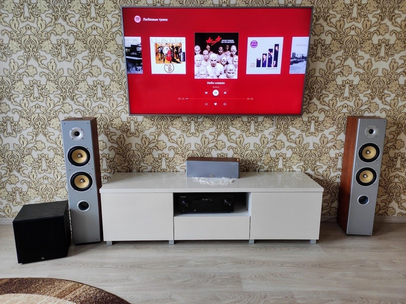
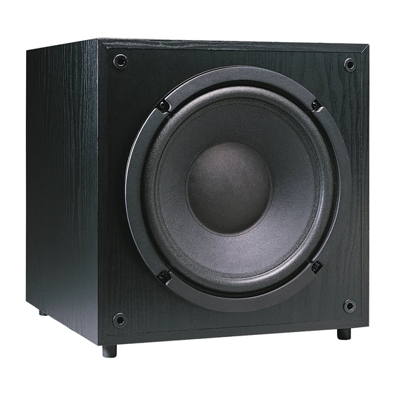
- ASW100
- Owner’s manual
-
Contents
-
Table of Contents
-
Troubleshooting
-
Bookmarks
Quick Links
SUBWOOFER OWNERS MANUAL
24 Brook Road, Rayleigh, Essex SS6 7XL. England.
Tel: +44 (0) 1268 740580 Fax: +44 (0) 1268 740589
info@monitoraudio.co.uk
www.monitoraudio.co.uk
Related Manuals for Monitor Audio ASW100
Summary of Contents for Monitor Audio ASW100
-
Page 1
SUBWOOFER OWNERS MANUAL 24 Brook Road, Rayleigh, Essex SS6 7XL. England. Tel: +44 (0) 1268 740580 Fax: +44 (0) 1268 740589 info@monitoraudio.co.uk www.monitoraudio.co.uk… -
Page 2
SUBWOOFER OWNERS MANUAL ASW100/FB110/FB210… -
Page 3
Monitor Audio Subwoofers Thank you for purchasing your Monitor Audio subwoofer, we trust it will enable you to have hours of continuous pleasure. All our speakers are hand crafted from top to bottom in our factories in England. Established in 1972, Monitor Audio has extensive experience in the use of traditional woodworking skills for our cabinets and state of the art technology for our drive units. -
Page 4
The equipment should be returned in its packing to the original supplier where possible, or to any other authorised Monitor Audio dealer. If it is not possible to return the equipment by hand, then it should be sent carriage prepaid via a reputable carrier. -
Page 5: Table Of Contents
Satellite Speaker wiring option 1 Speaker level high pass filter Main/Satellite speaker wiring option 2 Wiring with a pre amp and separate power amp Plugging in the Subwoofer Fine tuning Trouble shooting Specifications Guarantee and Service Claims under Guarantee © Monitor Audio Ltd 2001…
-
Page 6: Unpacking And Installation
Note: If the Subwoofer is not likely to be used for long periods, it is wise to switch off at the mains. This is a recommended safe practice in order to reduce the risk of electrical fire. © Monitor Audio Ltd 2001…
-
Page 7
Power Sources The appliance should be connected to a power supply only of the type described in the operating instructions or as marked on the product. © Monitor Audio Ltd 2001… -
Page 8
The appliance has been dropped or the enclosure damaged. Servicing The user should not attempt to service the appliance beyond that specified in the operating instructions. Qualified service personnel should carry out all other servicing requirement. © Monitor Audio Ltd 2001… -
Page 9: Mains Connection
Position/Location Your Monitor Audio Subwoofer should perform well in just about any room location. In fact unless your ear is within a couple of feet of the subwoofer, the bass should seem to radiate from your main speakers.
-
Page 10
ASW 100 / FB110 FB 210 Power switch with auto off facility RCA Phono inputs Mode switch High level inputs Level/Gain control High level outputs Crossover/Frequency control Fuse Phase control Mains connection RCA Phono outputs Voltage Selector 115/230V © Monitor Audio Ltd 2001… -
Page 11
1. Power Switch with Auto Off facility: The power switch provided for ASW100/FB110 has two positions: Off — Auto On. In the Auto On position the sub- woofer unit will remain in stand by mode until the unit receives an input signal. If the subwoofer unit does not receive a signal for around 15-20 minutes, it will switch to stand by mode until it receives a further signal. -
Page 12
12. Mains Voltage Selector should be factory set to your countries mains voltage specification. Do not attempt to adjust this as this may lead to permanent damage to the product and even the risk of fire. © Monitor Audio Ltd 2001… -
Page 13: Standard Amplifier — Speaker Cable Connection
Connect the amplifiers left channel Black (-) to the subwoofer left channel Black (-) ‘high level input’ terminals. Make a corresponding match connection to the right channel. See fig. 1 (showing ASW100/FB110) (If using two subwoofers connect one to each channel) Fig. 1…
-
Page 14: Satellite Speaker Wiring Option 1
Connect the subwoofer Black (-) ‘high level output’ terminal to the Black (-) terminal on the back of the main / satellite speaker. Make a matching connection to the right channel main/satellite. Fig. 2 AMPLIFIER SPEAKERS MONITOR AUDIO MONITOR AUDIO LEFT RIGHT SPEAKER SPEAKER © Monitor Audio Ltd 2001…
-
Page 15: Speaker Level High Pass Filter
Speaker-level high pass filter Monitor Audio’s subwoofers have a high pass filter. When your main/satellite speakers are connected to the ‘speaker output’ terminals on the subwoofer, the low bass frequencies below 100Hz are filtered from your main / satellite speakers.
-
Page 16: Main/Satellite Speaker Wiring Option 2
/ satellite speakers to your amplifier using the same high level output terminals as the subwoofer. Do not connect the main / satellite speakers to the subwoofer. Fig. 3 SPEAKERS AMPLIFIER MONITOR AUDIO MONITOR AUDIO LEFT RIGHT SPEAKER SPEAKER © Monitor Audio Ltd 2001…
-
Page 17
(left and right) on the subwoofer rear panel. See Fig. 4 if you are using two subwoofers, simply connect one subwoofer per channel. Fig. 4 PREAMP MAIN MAIN OUT 1 OUT 2 POWER AMP SPEAKERS MAIN INPUT MONITOR AUDIO MONITOR AUDIO LEFT RIGHT SPEAKER SPEAKER © Monitor Audio Ltd 2001… -
Page 18: Plugging In The Subwoofer
Note: If the Subwoofer is not likely to be used for long periods, it is wise to switch off at the mains. This is a recommended safe practice in order to reduce the risk of electrical fire. © Monitor Audio Ltd 2001…
-
Page 19: Trouble Shooting
Check that this is not caused by items located on top of or close to the subwoofer which may vibrate when subject to deep bass sounds If problems persist contact your dealer immediately for assistance. © Monitor Audio Ltd 2001…
-
Page 20: Specifications
” x 14 ” Weight 12Kg / 26lb 15Kg / 33lb 24Kg / 53lb Input Voltage (Mains) 90 — 125V 90 — 125V 90 — 125V 115V 220 — 250V 220 — 250V 220 — 250V 230V © Monitor Audio Ltd 2001…
Page 1 — User Manual
AM700Audio Measurement Setwith Color Display070-9585-01User ManualThis document applies to firmware version 1.02and above.
Page 2
Table of Contentsii AM700 Audio Measurement SetMenu 2-9. . . . . . . . . . . . . . . . . . . . . . . . . . . . . . . . . . . . . . . . . . . . . . . .
Page 3
Configuring the AM7003-14 AM700 Audio Measurement Set User ManualFigure 3-10: The Copy Configuration menuTo delete all copies from the spooler, press
Page 4
Configuring the AM700 AM700 Audio Measurement Set User Manual3-15When the Copy Format is either PostScript or TIFF, the Copy Style can be set toColor.
Page 5 — WARRANTY
Configuring the AM7003-16 AM700 Audio Measurement Set User ManualFigure 3-11: Hard copy output file selectorCopy Styles. You can select the choice of
Page 6
Configuring the AM700 AM700 Audio Measurement Set User Manual3-17Figure 3-12: System Setup Communicate Configuration menuSaving Changes and Exiting th
Page 7 — EC Declaration of Conformity
Configuring the AM7003-18 AM700 Audio Measurement Set User ManualWhen Audio Analyzer, FFT Analyzer, or Monitor is the running application,calibration
Page 8
Configuring the AM700 AM700 Audio Measurement Set User Manual3-19When the generator is driving an output load of 600 Ω, and the internal seriesresisto
Page 9
Configuring the AM7003-20 AM700 Audio Measurement Set User ManualInternal seriesresistorUser loadresistanceEoutFigure 3-14: AM700 generator output vol
Page 10 — AM700 Audio Measurement Set
Configuring the AM700 AM700 Audio Measurement Set User Manual3-21Digital Audio Sampling Rate. In certain situations, the actual sample rate of a digit
Page 11 — Applications
Configuring the AM7003-22 AM700 Audio Measurement Set User ManualQuick SetupOne of the configuration choices is the Quick Setup selection. Under this
Page 12
Configuring the AM700 AM700 Audio Measurement Set User Manual3-23Table 3-1: Quick Setups by Application Application MeasurementsViews Displayed(Views
Page 13
Table of Contents AM700 Audio Measurement SetiiiKeypad Entry Buttons 2-29. . . . . . . . . . . . . . . . . . . . . . . . . . . . . . . . . . . . . . .
Page 14 — Appendices
Configuring the AM7003-24 AM700 Audio Measurement Set User ManualTable 3-1: Quick Setups by Application (Cont.)ApplicationViews Displayed(Views availa
Page 17
AM700 Audio Measurement Set User Manual4-1ApplicationsThis section of the User Manual describes the many audio applications and user-selectable featu
Page 18
Audio Generator4-2 AM700 Audio Measurement Set User ManualSignal Postprocessing. A phase offset can be imposed between the digital generatoroutput sig
Page 19 — List of Tables
Audio Generator AM700 Audio Measurement Set User Manual4-3Control. Press the Control button to display the Generator Control panel shown inFigure 4-2
Page 20
Audio Generator4-4 AM700 Audio Measurement Set User ManualUse the Generator Selection display shown in Figure 4-2 to specify the followinggenerator fu
Page 21 — General Safety Summary
Audio Generator AM700 Audio Measurement Set User Manual4-5Follow Mode. Controls are always assigned to at least one generator. They can beassigned to
Page 22 — Safety Terms and Symbols
Audio Generator4-6 AM700 Audio Measurement Set User ManualAvailable waveforms include the following:Sine. The most common waveform used in audio analy
Page 23
Audio Generator AM700 Audio Measurement Set User Manual4-7NOTE. Note: SMPTE and CCIF signal parameters are defined by these organiza-tions. Changing t
Page 24
Table of Contentsiv AM700 Audio Measurement SetGenerator Selection 4-4. . . . . . . . . . . . . . . . . . . . . . . . . . . . . . . . . . . . . . . .
Page 25
Audio Generator4-8 AM700 Audio Measurement Set User ManualOn playback, the contents of the audio source file are copied into a buffer and thegenerator
Page 26
Audio Generator AM700 Audio Measurement Set User Manual4-9Jittered Sine (digital generator in AES mode only). This selection adds a sine wave onthe au
Page 28 — Operation and Controls
Audio Generator AM700 Audio Measurement Set User Manual4-11The following explains the format of an AM700 multitone file:<Header><Data>wher
Page 29 — Measurement Capability
Audio Generator4-12 AM700 Audio Measurement Set User ManualTo select a multitone description file, in the Waveform Control screen, touch theFilename s
Page 30 — Installation of the AM700
Audio Generator AM700 Audio Measurement Set User Manual4-13For example, if you want a multitone signal with 10 tones, a record length of 1024,at a sam
Page 31 — CAUTION
Audio Generator4-14 AM700 Audio Measurement Set User Manualtime required to acquire the record increases a small amount, but you benefit fromthe impro
Page 32
Audio Generator AM700 Audio Measurement Set User Manual4-15You have two ways to adjust generator frequency and amplitude:H From the Generator Status p
Page 33
Audio Generator4-16 AM700 Audio Measurement Set User ManualH The assignment of the Amplitude and Frequency control knobs (shown by thesmall circular a
Page 34
Audio Generator AM700 Audio Measurement Set User Manual4-17If necessary, select the desired waveform from the Waveform pop-up selection. Setthe amplit
Page 35
Table of Contents AM700 Audio Measurement SetvControlling Plotted Data 4-58. . . . . . . . . . . . . . . . . . . . . . . . . . . . . . . . . . . . . .
Page 36
Audio Generator4-18 AM700 Audio Measurement Set User ManualFigure 4-6: Waveform control displayThe amplitude and frequency setting for the selected ge
Page 37
Audio Generator AM700 Audio Measurement Set User Manual4-19Sweep ControlThe Sweep Control screen allows you to change the sine wave parameters thatdef
Page 38 — User-supplied Accessories
Audio Generator4-20 AM700 Audio Measurement Set User ManualNOTE. When running a voltage sweep, especially with Automatic Timing enabled,the Input Rang
Page 39 — Operating Basics
Audio Generator AM700 Audio Measurement Set User Manual4-21Automatic Timing. When auto timing the sweep, the dwell times are calculated andset for the
Page 40
Audio Generator4-22 AM700 Audio Measurement Set User ManualNOTE. To use the list parameters to generate a frequency sweep, you must set FreqMode to Li
Page 41 — Operating Basics
Audio Generator AM700 Audio Measurement Set User Manual4-23The default list has frequencies given in ascending order to match the standardpractice of
Page 42
Audio Generator4-24 AM700 Audio Measurement Set User ManualAdvanced Digital AudioControls in the Advanced Digital Audio screen (see Figure 4-9) includ
Page 43
Audio Generator AM700 Audio Measurement Set User Manual4-25Word Size. Use this field editor to specify the number of audio bits that are sent in adigi
Page 44
Audio Generator4-26 AM700 Audio Measurement Set User ManualUser Bits. Touching this soft key displays a menu from which you can select the typeof user
Page 45
Audio Generator AM700 Audio Measurement Set User Manual4-27Data. The data in the example file is:00000000 10000000 000000000 0 00 0 00 0 00 0 00 0 00
Page 46
Table of Contentsvi AM700 Audio Measurement SetInput Select 4-103. . . . . . . . . . . . . . . . . . . . . . . . . . . . . . . . . . . . . . . . . . .
Page 47
Audio Generator4-28 AM700 Audio Measurement Set User ManualUser Bit and Cstatus File Locations. The AM700 expects these files to be in certaindirector
Page 48 — Front-panel Operation
Audio Generator AM700 Audio Measurement Set User Manual4-29To switch between NVRAM and ROM, touch the Drive soft key. If there is adirectory available
Page 49 — System Control Buttons
Audio Generator4-30 AM700 Audio Measurement Set User ManualFigure 4-11: Advanced Digital Interface displayFrequency Mode. Touch this soft key to disp
Page 50
Audio Generator AM700 Audio Measurement Set User Manual4-31Variable Freq. Edit this field to specify the clock frequency when in VariableFrequency mod
Page 51
Audio Generator4-32 AM700 Audio Measurement Set User ManualAdvanced Analog ControlsSelections in the top two rows of the Advanced Analog Controls choi
Page 52
Audio Generator AM700 Audio Measurement Set User Manual4-33Because this is an analog bandpass filter, time is required to center the filter during asw
Page 53
Audio Generator4-34 AM700 Audio Measurement Set User ManualChanging Display Measurement Units in the Status PanelIf you want to change display units (
Page 54 — Applications Buttons
Audio Generator AM700 Audio Measurement Set User Manual4-35Set ReferenceWithin the generator status window you can set a generator frequency or levels
Page 55
Audio Generator4-36 AM700 Audio Measurement Set User Manual
Page 56
AM700 Audio Measurement Set User Manual4-37Audio AnalyzerThe AM700 Audio Analyzer application provides both graphical displays of audiomeasurements m
Page 57 — Utilities Buttons
Table of Contents AM700 Audio Measurement Set viiList of FiguresFigure 1-1: Rear panel fuse, power connector, On/Off Switch, and line selector 1-5. .
Page 58
Audio Analyzer4-38 AM700 Audio Measurement Set User ManualAcquired audio samples can be processed through one of several standard filtersbefore the me
Page 59
Audio Analyzer AM700 Audio Measurement Set User Manual4-39level difference. Its source can be either Channel 1 or Channel 2. You can plot adependent v
Page 60
Audio Analyzer4-40 AM700 Audio Measurement Set User ManualRegulation Mode MeasurementsLike XY measurement mode, Regulation mode can be accessed when y
Page 61
Audio Analyzer AM700 Audio Measurement Set User Manual4-41measured THD as set in the Target Value field editor (the starting and endingfrequencies are
Page 62
Audio Analyzer4-42 AM700 Audio Measurement Set User ManualDelay Time. Most devices that you might test with Regulation mode do not haveinstantaneous r
Page 63
Audio Analyzer AM700 Audio Measurement Set User Manual4-43Figure 4-17: Regulation mode with Plot Control menuWhen the selected view is displaying a Re
Page 64
Audio Analyzer4-44 AM700 Audio Measurement Set User ManualFigure 4-18: View Setup for Regulation mode measurementsTouch the Start Regulation soft key
Page 65
Audio Analyzer AM700 Audio Measurement Set User Manual4-45Bandpass of deviceunder test left channelA Generator outputlevel versus freq plotB Generator
Page 66
Audio Analyzer4-46 AM700 Audio Measurement Set User ManualSome knowledge of the type of information you want to extract from a measurementis required
Page 67
Audio Analyzer AM700 Audio Measurement Set User Manual4-47b. Select Generator as the Sweep Source (this puts the Analyzer in closed-loop mode). Notice
Page 68 — Sweep / Run Button
Table of Contents AM700 Audio Measurement SetviiiFigure 2-30: GPIB connector 2-39. . . . . . . . . . . . . . . . . . . . . . . . . . . . . . . . . . .
Page 69 — Keypad Entry Buttons
Audio Analyzer4-48 AM700 Audio Measurement Set User ManualThe following procedure describes how to select the generator and waveforms:1. Press the Con
Page 70
Audio Analyzer AM700 Audio Measurement Set User Manual4-493. Touch Sweep Control to display the Sweep Control settings. Notice the message“Sweep timin
Page 72
Audio Analyzer AM700 Audio Measurement Set User Manual4-51Refer to Controlling Plotted Data on 4-58 for directions about how to keep a historyof trace
Page 73
Audio Analyzer4-52 AM700 Audio Measurement Set User ManualMaking Valid MeasurementsThe Audio Analyzer application must be configured properly if it is
Page 74 — Floppy Disk Drive
Audio Analyzer AM700 Audio Measurement Set User Manual4-53Touch the Accept Changes soft key (or the Cancel soft key) to exit the InputConfiguration di
Page 75
Audio Analyzer4-54 AM700 Audio Measurement Set User ManualThe Input Select choices allow you to select from analog high-resolution, analoghigh-bandwid
Page 76
Audio Analyzer AM700 Audio Measurement Set User Manual4-55Real Time Readout of MeasurementsA real time display of the Audio Analyzer measurement reado
Page 77
Audio Analyzer4-56 AM700 Audio Measurement Set User ManualYou can improve the measurement speed of the Analyzer by disabling (shutting off)unneeded me
Page 78
Audio Analyzer AM700 Audio Measurement Set User Manual4-57NOTE. If measurements on either Channel 1 or Channel 2 are not enabled, stereomeasurements c
Page 79
Table of Contents AM700 Audio Measurement Set ixFigure 4-16: General controls with Regulation mode menu selections 4-40. . . . . . . . . . . . . . . .
Page 80
Audio Analyzer4-58 AM700 Audio Measurement Set User ManualControlling Plotted DataUse the selections in the Plot Control screen to control the plotted
Page 81
Audio Analyzer AM700 Audio Measurement Set User Manual4-59Figure 4-24: Graphical display with Plot Control menuTouch the Erase All Plots soft key to e
Page 82
Audio Analyzer4-60 AM700 Audio Measurement Set User ManualConfiguring MeasurementsAudio Analyzer has up to four graphical views of a measurement and t
Page 83
Audio Analyzer AM700 Audio Measurement Set User Manual4-61Regulation mode can be used, for example, to produce a plot of the generator outputlevel ver
Page 84
Audio Analyzer4-62 AM700 Audio Measurement Set User ManualFigure 4-25: Sweep detection controlsSweep Detection On. In open-loop operation, the sweep d
Page 85
Audio Analyzer AM700 Audio Measurement Set User Manual4-63When a frequency sweep is selected the Frequency choice in the Minimum Rise/Fallmenu is enab
Page 86
Audio Analyzer4-64 AM700 Audio Measurement Set User ManualIt is possible to set up a different sweep setting for each measurement. If somemeasurements
Page 87
Audio Analyzer AM700 Audio Measurement Set User Manual4-65Sweep startStart lookingfor settled dataSettled dataView 1Settled dataView 1GeneratorstepsDe
Page 88 — Configuration
Audio Analyzer4-66 AM700 Audio Measurement Set User ManualTouch the Settled soft key in the Configure Measurements Setup screen to displaythe Settled
Page 89
Audio Analyzer AM700 Audio Measurement Set User Manual4-67Settling Detector Enable. Checking the Enable Settling Detector causes the AudioAnalyzer to
Page 90
Table of Contents AM700 Audio Measurement SetxFigure 4-49: Dual channel display showing different signals on Channel 1 and Channel 2 4-98. . . . . . .
Page 91
Audio Analyzer4-68 AM700 Audio Measurement Set User ManualA flat settling curve applies the Tolerance and Resolution parameters backwardshorizontally
Page 92
Audio Analyzer AM700 Audio Measurement Set User Manual4-69NOTE. In Regulation mode, continuous rapid plotting of unsettled data pointstypically means
Page 93
Audio Analyzer4-70 AM700 Audio Measurement Set User ManualResolution. This setting is in units appropriate to the measurement being made. Theresolutio
Page 94
Audio Analyzer AM700 Audio Measurement Set User Manual4-71Acquiring a Reference. Set up the Audio Analyzer and make a measurement thatprovides a trace
Page 95
Audio Analyzer4-72 AM700 Audio Measurement Set User ManualMeasurement tracedBuPressSet RefdBuSet verticalaxis to dBrdBr0–500–500Reference memory trace
Page 96
Audio Analyzer AM700 Audio Measurement Set User Manual4-73Figure 4-31: Relative to Reference setup menuTouch Enter or Done to save the file name and e
Page 97 — Measurement Setup Menu
Audio Analyzer4-74 AM700 Audio Measurement Set User ManualNOTE. A reference trace is not displayed for comparison. The plot of new data showsthe diffe
Page 98
Audio Analyzer AM700 Audio Measurement Set User Manual4-75Input FilteringThe AM700 provides several weighting and bandwidth limiting filters. Weightin
Page 99 — System Setup Menu
Audio Analyzer4-76 AM700 Audio Measurement Set User ManualFigure 4-32: Filter menu selection with Audio AnalyzerH Touch the Channel 1 or Channel 2 sof
Page 100 — Configuring the AM700
Audio Analyzer AM700 Audio Measurement Set User Manual4-77CCIR 468CCIR ARMA WeightingFigure 4-33: Filter curves: CCIR 468, CCIR ARM, and A Weighting
Page 101
Table of Contents AM700 Audio Measurement Set xiList of TablesTable 1-1: Optional Power Cords 1-7. . . . . . . . . . . . . . . . . . . . . . . . . .
Page 102
Audio Analyzer4-78 AM700 Audio Measurement Set User ManualB WeightingC WeightingC MessageFigure 4-34: Filter Curves: B Weighting, C Weighting, and C M
Page 103
Audio Analyzer AM700 Audio Measurement Set User Manual4-79F Weighting15 kHz, 20 kHz, and22 kHz Low Pass400 Hz High PassFigure 4-35: Filter Curves: F W
Page 104
Audio Analyzer4-80 AM700 Audio Measurement Set User ManualCursorsCursors can be used to select measurement points in a waveform. Cursor position isadj
Page 105
AM700 Audio Measurement Set User Manual4-81FFT AnalyzerAn audio signal is composed of many frequency components. Some of thesecomponents can be due t
Page 106
FFT Analyzer4-82 AM700 Audio Measurement Set User ManualMeasurement BandwidthThe FFT Analyzer has two measurement bandwidths. The high resolution mode
Page 107
FFT Analyzer AM700 Audio Measurement Set User Manual4-83Figure 4-37: FFT Analyzer Window menu displayKaiser-Bessel. The K-B window produces improved
Page 108 — Quick Setup
FFT Analyzer4-84 AM700 Audio Measurement Set User ManualHannFlat-topKaiser-BesselBest selectivity if the signal frequency is exactly equalto a frequen
Page 109
FFT Analyzer AM700 Audio Measurement Set User Manual4-85am700 window 1.00.01 0.015 0.020 etc. for 513 numbers separated by white space. Spaces,tabs, a
Page 110
FFT Analyzer4-86 AM700 Audio Measurement Set User ManualSpectrogram. This is a display of time versus frequency versus amplitude.Amplitude is color co
Page 111
FFT Analyzer AM700 Audio Measurement Set User Manual4-87Contrast is adjustable using the scaling on the vertical axis of the Spectrogramdisplay. Selec
Page 114
FFT Analyzer4-88 AM700 Audio Measurement Set User ManualFigure 4-40: FFT Input Select and Input Range menusCursorsCursors can be used to select measur
Page 115
FFT Analyzer AM700 Audio Measurement Set User Manual4-89AveragingAveraging is available for the FFT Analyzer displays. Pressing the Average buttonligh
Page 116
FFT Analyzer4-90 AM700 Audio Measurement Set User ManualFigure 4-41: Zoomed FFT display showing maximum expansion of the traceMultitone Measurement Mo
Page 117
FFT Analyzer AM700 Audio Measurement Set User Manual4-91waves at several frequencies. From the received multitone signal, Multitonemeasurements produc
Page 118
FFT Analyzer4-92 AM700 Audio Measurement Set User ManualThe files of multitones that are included in the rom:/mtone directory are thosegenerated by th
Page 119
FFT Analyzer AM700 Audio Measurement Set User Manual4-93Figure 4-43: Multitone measurement settings in the Configure Measurements menuThese measuremen
Page 120
FFT Analyzer4-94 AM700 Audio Measurement Set User ManualFigure 4-44: FFT View SetupA typical multitone graphical display showing a two-view display is
Page 121
FFT Analyzer AM700 Audio Measurement Set User Manual4-95Figure 4-45: Multitone Analyzer display with two measurement windowsFigure 4-46: Display of FF
Page 122
FFT Analyzer4-96 AM700 Audio Measurement Set User ManualFigure 4-47: FFT multitone table displayNOTE. The amplitude of an individual tone in a multito
Page 123
AM700 Audio Measurement Set User Manual4-97Audio MonitorYou can use the Audio Monitor application to make time-domain measurements ofsignal amplitude
Page 124
AM700 Audio Measurement Set User ManualxiiiGeneral Safety SummaryReview the following safety precautions to avoid injury andprevent damage to this pro
Page 125 —
Audio Monitor4-98 AM700 Audio Measurement Set User ManualDisplaysAudio Monitor provides a one- or two-channel view of signal amplitude versus time.At
Page 126
Audio Monitor AM700 Audio Measurement Set User Manual4-99To configure Audio Monitor views, touch the Setup icon to display the View Setupscreen, then
Page 127
Audio Monitor4-100 AM700 Audio Measurement Set User ManualFrom the View Setup screen displayed when you touch the Setup icon (seeFigure 4-50) you can
Page 128
Audio Monitor AM700 Audio Measurement Set User Manual4-101Saving Changes and Exiting View Setup Menu. At the bottom of the control panel arethe choice
Page 129 — Waveform Control
Audio Monitor4-102 AM700 Audio Measurement Set User ManualFigure 4-52: Use of Cursors to measure pulse timePressing the Cursors button places two curs
Page 130
Audio Monitor AM700 Audio Measurement Set User Manual4-103MenuPressing the Menu button displays the Audio Monitor selections and correspondingsubmenus
Page 131 — Sweep Control
Audio Monitor4-104 AM700 Audio Measurement Set User ManualThe Input Select submenu also allows you to select input source: Analog HighResolution, Anal
Page 132
Audio Monitor AM700 Audio Measurement Set User Manual4-105External trigger can be used to determine the phase difference relationship betweentwo signa
Page 133
Audio Monitor4-106 AM700 Audio Measurement Set User Manual
Page 134
4-107 AM700 Audio Measurement Set User ManualDigital Interface TesterUse the Digital Interface Tester application to make extensive evaluations of the
Page 135
General Safety SummaryAM700 Audio Measurement Set User ManualxivTo avoid electric shock, do not operate this product in wet or dampconditions.To avoid
Page 136 — Advanced Digital Audio
Digital Interface Tester4-108 AM700 Audio Measurement Set User ManualEye Diagram Display. Use the Eye Diagram display to present a straightforwardindi
Page 137
Digital Interface Tester4-109 AM700 Audio Measurement Set User ManualFigure 4-56: Digital Interface Tester Input Configuration menuNo Signal. When the
Page 138
Digital Interface Tester4-110 AM700 Audio Measurement Set User ManualView SetupMake the choices for View Types and View Options in this menu. Choices
Page 139
Digital Interface Tester4-111 AM700 Audio Measurement Set User ManualAcross the top of the Digital Interface Tester you see the view selection bar ass
Page 140
Digital Interface Tester4-112 AM700 Audio Measurement Set User ManualBit Probability DisplayView the bit activity for the serial digital frames using
Page 141 — Advanced Digital Interface
Digital Interface Tester4-113 AM700 Audio Measurement Set User ManualChannel Status DisplayView the bit values (ones and zeros) of the digital signal
Page 142
Digital Interface Tester4-114 AM700 Audio Measurement Set User ManualX/Z and Y Subframes. X/Z is digital subframe 1 and Y is digital subframe 2 from t
Page 143
Digital Interface Tester4-115 AM700 Audio Measurement Set User ManualProfessionalgradeConsumergradeFigure 4-62: Decoded channel-status data display
Page 144 — Advanced Analog Controls
Digital Interface Tester4-116 AM700 Audio Measurement Set User ManualEye Diagram DisplayUse the eye diagram display seen in Figure 4-63 is to view bin
Page 145
Digital Interface Tester4-117 AM700 Audio Measurement Set User Manualsufficient for the receiver to clearly detect whether a high or a low logic level
Page 146
General Safety SummaryAM700 Audio Measurement Set User ManualxvCAUTION. Caution statements identify conditions or practices thatcould result in damage
Page 147 — Set Reference
Digital Interface Tester4-118 AM700 Audio Measurement Set User ManualLong cablesimulator onlyLong cablesimulator withjitter addedFigure 4-64: Eye Diag
Page 148
Digital Interface Tester4-119 AM700 Audio Measurement Set User ManualDigital Jitter MeasurementIf several pieces of equipment are cascaded, jitter may
Page 149 — Audio Analyzer
Digital Interface Tester4-120 AM700 Audio Measurement Set User ManualFigure 4-66: Jitter View TypesAs with the FFT Analyzer, the jitter spectrum displ
Page 150 — XY Measurement Mode
Digital Interface Tester4-121 AM700 Audio Measurement Set User ManualBar graphdisplay of jitterspectrumSpectrogramdisplay of jitterspectrumFigure 4-67
Page 151
Digital Interface Tester4-122 AM700 Audio Measurement Set User ManualDigital Interface Tester Main MenuThe Digital Interface Tester menu selections pr
Page 153
Digital Interface Tester4-124 AM700 Audio Measurement Set User ManualBNC Output. Specifies the output voltage of the digital BNC connector. This iscon
Page 154
Digital Interface Tester4-125 AM700 Audio Measurement Set User ManualThe menu choices here control the low frequency jitter rejection bandwidth, theji
Page 155
Digital Interface Tester4-126 AM700 Audio Measurement Set User ManualTable 4-1: Subframe Time Slots Time Slots Information Carried0 to 3 One of the th
Page 156
Digital Interface Tester4-127 AM700 Audio Measurement Set User ManualDigital Interface TerminologySampling frequency Frequency of the audio signal sam
Page 157
General Safety SummaryAM700 Audio Measurement Set User Manualxvi
Page 158
Digital Interface Tester4-128 AM700 Audio Measurement Set User ManualBlock A block is 192 consecutive frames in a group.Channel coding Coding describe
Page 159
AM700 Audio Measurement Set User Manual4-129Function OperationAM700 functions are user-defined sequences of commands. Functions can bewritten in SCPI
Page 160
Function Operation4-130 AM700 Audio Measurement Set User ManualFunctions are stored in two different directories in the AM700. Those stored inrom:/fun
Page 161
Function Operation AM700 Audio Measurement Set User Manual4-131H If double quote marks are used in a SCPI command, they must be escaped by abackslash
Page 162
Function Operation4-132 AM700 Audio Measurement Set User Manual#Start the Audio Monitor applicationscpi INST:SEL MONITOR#Display two measurement windo
Page 163
Function Operation AM700 Audio Measurement Set User Manual4-133Figure 4-71: Storage Manager control screenCopying a File. Copying a file from a floppy
Page 164 — Configuring Input Channels
Function Operation4-134 AM700 Audio Measurement Set User Manual5. Touch Drive on the left side of the Storage Manager to select dos:. A list of thedir
Page 165 — Selecting Input Options
Function Operation AM700 Audio Measurement Set User Manual4-135A cron_string is five fields consisting of the following:MIN HOUR DAY_of_MONTH MONTH DA
Page 166
Function Operation4-136 AM700 Audio Measurement Set User ManualPROG:EXPL commands are used in the same manner as the PROG:SEL commandsbut explicitly n
Page 167
Function Operation AM700 Audio Measurement Set User Manual4-137The AM700 State Save function saves the following settings:H Application settingsH Gene
Page 169
Function Operation4-138 AM700 Audio Measurement Set User Manual
Page 172 — Configuring Measurements
AM700 Audio Measurement Set User ManualA-1Appendix A: SpecificationsThe performance limits in this specification are valid with the following conditi
Page 173
Appendix A: SpecificationsA-2 AM700 Audio Measurement Set User ManualTable A-1: Analog Analyzer Specifications (Cont.)Capabilities DescriptionInput Ch
Page 174
Appendix A: Specifications AM700 Audio Measurement Set User ManualA-3Table A-1: Analog Analyzer Specifications (Cont.)Capabilities DescriptionInput Ch
Page 175
Appendix A: SpecificationsA-4 AM700 Audio Measurement Set User ManualTable A-1: Analog Analyzer Specifications (Cont.)Capabilities DescriptionInput Ch
Page 176
Appendix A: Specifications AM700 Audio Measurement Set User ManualA-5Table A-1: Analog Analyzer Specifications (Cont.)Capabilities DescriptionInput Ch
Page 177
Appendix A: SpecificationsA-6 AM700 Audio Measurement Set User ManualTable A-1: Analog Analyzer Specifications (Cont.)Capabilities DescriptionAmplitud
Page 178
Appendix A: Specifications AM700 Audio Measurement Set User ManualA-7Table A-1: Analog Analyzer Specifications (Cont.)Capabilities DescriptionAmplitud
Page 180
Appendix A: SpecificationsA-8 AM700 Audio Measurement Set User ManualTable A-1: Analog Analyzer Specifications (Cont.)Capabilities DescriptionTHD + N
Page 181
Appendix A: Specifications AM700 Audio Measurement Set User ManualA-9Table A-1: Analog Analyzer Specifications (Cont.)Capabilities DescriptionTHD + N
Page 182
Appendix A: SpecificationsA-10 AM700 Audio Measurement Set User ManualTable A-2: Electronic Triggers Specifications Capabilities DescriptionTrigger In
Page 183
Appendix A: Specifications AM700 Audio Measurement Set User ManualA-11Table A-3: Analog Generator Specifications (Cont.)Capabilities DescriptionOutput
Page 184
Appendix A: SpecificationsA-12 AM700 Audio Measurement Set User ManualTable A-3: Analog Generator Specifications (Cont.)Capabilities DescriptionAmplit
Page 185
Appendix A: Specifications AM700 Audio Measurement Set User ManualA-13Table A-3: Analog Generator Specifications (Cont.)Capabilities DescriptionAmplit
Page 186
Appendix A: SpecificationsA-14 AM700 Audio Measurement Set User ManualTable A-3: Analog Generator Specifications (Cont.)Capabilities DescriptionAmplit
Page 187 — Input Filtering
Appendix A: Specifications AM700 Audio Measurement Set User ManualA-15Table A-3: Analog Generator Specifications (Cont.)Capabilities DescriptionTHD +
Page 188
Appendix A: SpecificationsA-16 AM700 Audio Measurement Set User ManualTable A-4: Digital Audio Unit Specifications Capabilities DescriptionThe Digital
Page 189
Appendix A: Specifications Revised January 1995AM700 Audio Measurement Set User ManualA-17Table A-4: Digital Audio Unit Specifications (Cont.)Capabili
Page 190
AM700 Audio Measurement Set User Manual1-1Introduction and InstallationThe Tektronix AM700 Audio Measurement System is a programmable, high-performan
Page 191 — 400 Hz High Pass
Appendix A: SpecificationsA-18 AM700 Audio Measurement Set User ManualTable A-4: Digital Audio Unit Specifications (Cont.)Capabilities DescriptionRece
Page 192 — Generator Status Readout
Appendix A: Specifications AM700 Audio Measurement Set User ManualA-19Table A-4: Digital Audio Unit Specifications (Cont.)Capabilities DescriptionRece
Page 193 — FFT Analyzer
Appendix A: SpecificationsA-20 AM700 Audio Measurement Set User ManualTable A-4: Digital Audio Unit Specifications (Cont.)Capabilities DescriptionRefe
Page 194 — Windowing
Appendix A: Specifications AM700 Audio Measurement Set User ManualA-21Table A-4: Digital Audio Unit Specifications (Cont.)Capabilities DescriptionGene
Page 195
Appendix A: SpecificationsA-22 AM700 Audio Measurement Set User ManualTable A-4: Digital Audio Unit Specifications (Cont.)Capabilities DescriptionRefe
Page 196
Appendix A: Specifications AM700 Audio Measurement Set User ManualA-23Table A-5: Display System Capabilities DescriptionDisplayDisplay Type Color LCD
Page 197 — Displays
Appendix A: SpecificationsA-24 AM700 Audio Measurement Set User ManualTable A-5: Display System (Cont.)Capabilities DescriptionVGA OutputTiming Signa
Page 198
Appendix A: Specifications AM700 Audio Measurement Set User ManualA-25Table A-7: Nonvolatile Memory Capabilities DescriptionBattery-backed SRAMStorage
Page 199 — Input Range
Appendix A: SpecificationsA-26 AM700 Audio Measurement Set User ManualTable A-9: Front Panel Hardware Capabilities DescriptionAudio Input and Output C
Page 200
Appendix A: Specifications AM700 Audio Measurement Set User ManualA-27Table A-10: Rear Panel Hardware (Cont.)Capabilities DescriptionCOM1 and COM2 Con
Page 201 — Averaging
Introduction and Installation1-2 AM700 Audio Measurement Set User ManualH The SOUND function in all applications (except Digital Interface Tester) all
Page 202 — Multitone Measurement Mode
Appendix A: SpecificationsA-28 AM700 Audio Measurement Set User ManualTable A-12: Safety Standards Category StandardsU.S. Nationally Recognized Testin
Page 203
Appendix A: Specifications AM700 Audio Measurement Set User ManualA-29Table A-14: Environmental Characteristics Capabilities DescriptionAtmosphericsTe
Page 204
Appendix A: SpecificationsA-30 AM700 Audio Measurement Set User ManualTable A-15: Dynamic Characteristics (Cont.)Capabilities DescriptionShockLoose Lo
Page 205
Appendix A: Specifications AM700 Audio Measurement Set User ManualA-31Table A-16: Electromagnetic Compatibility Capabilities DescriptionEMC Requiremen
Page 207
Appendix A: Specifications AM700 Audio Measurement Set User ManualA-33Table A-17: Mechanical Characteristics Capabilities DescriptionStandard Instrume
Page 208
Appendix A: SpecificationsA-34 AM700 Audio Measurement Set User ManualTable A-17: Mechanical Characteristics (Cont.)Capabilities DescriptionRackmounte
Page 209 — Audio Monitor
Appendix A: Specifications AM700 Audio Measurement Set User ManualA-35Table A-19: Generator Control Capabilities DescriptionGenerator Capabilities The
Page 210
Appendix A: SpecificationsA-36 AM700 Audio Measurement Set User ManualTable A-19: Generator Control (Cont.)Capabilities DescriptionTime-Dependent Sign
Page 211
Appendix A: Specifications AM700 Audio Measurement Set User ManualA-37Table A-20: Generator Signals Capabilities DescriptionGenerated SignalsSine A si
Page 212
Introduction and Installation AM700 Audio Measurement Set User Manual1-3a cluttered viewing area. The display screens can be formatted for any externa
Page 213
Appendix A: SpecificationsA-38 AM700 Audio Measurement Set User ManualTable A-20: Generator Signals (Cont.)Capabilities DescriptionGenerated SignalsCh
Page 214
Appendix A: Specifications AM700 Audio Measurement Set User ManualA-39Table A-21: Audio Analyzer Application Capabilities DescriptionHuman InterfaceTh
Page 215
Appendix A: SpecificationsA-40 AM700 Audio Measurement Set User ManualTable A-21: Audio Analyzer Application (Cont.)Capabilities DescriptionAcquisitio
Page 216
Appendix A: Specifications AM700 Audio Measurement Set User ManualA-41Table A-21: Audio Analyzer Application (Cont.)Capabilities DescriptionMeasuremen
Page 217
Appendix A: SpecificationsA-42 AM700 Audio Measurement Set User ManualTable A-22: FFT Analyzer Capabilities DescriptionFrequency Related Characteristi
Page 218
Appendix A: Specifications AM700 Audio Measurement Set User ManualA-43Table A-22: FFT Analyzer (Cont.)Capabilities DescriptionFrequency Related Charac
Page 219 — Digital Interface Tester
Appendix A: SpecificationsA-44 AM700 Audio Measurement Set User ManualTable A-22: FFT Analyzer (Cont.)Capabilities DescriptionAmplitude Related Charac
Page 220
Appendix A: Specifications AM700 Audio Measurement Set User ManualA-45Table A-22: FFT Analyzer (Cont.)Capabilities DescriptionCursor FunctionsNumber o
Page 221
Appendix A: SpecificationsA-46 AM700 Audio Measurement Set User ManualTable A-22: FFT Analyzer (Cont.)Capabilities DescriptionMultitoneMultitone Detec
Page 222 — View Setup
Appendix A: Specifications AM700 Audio Measurement Set User ManualA-47Table A-23: Audio Monitor Capabilities DescriptionHuman InterfaceThis applicatio
Page 223
The following copyright covers this manual for the AM700.Copyright Tektronix, Inc. All rights reserved. Printed in the United States of America. Con
Page 224 — Bit Probability Display
Introduction and Installation1-4 AM700 Audio Measurement Set User ManualThe digital generator is also very flexible. It can produce test signals in AE
Page 225 — Channel Status Display
Appendix A: SpecificationsA-48 AM700 Audio Measurement Set User ManualTable A-23: Audio Monitor (Cont.)Capabilities DescriptionOscilloscope DisplayTi
Page 226
Appendix A: Specifications AM700 Audio Measurement Set User ManualA-49Table A-24: Digital Interface Tester Capabilities DescriptionIntended Use The di
Page 227
Appendix A: SpecificationsA-50 AM700 Audio Measurement Set User ManualTable A-24: Digital Interface Tester (Cont.)Capabilities DescriptionEye Diagram
Page 230 — Cable simulator
AM700 Audio Measurement Set User ManualIndex-1IndexAAccessoriesNon Tektronix supplied, 1-12Optional, 1-12Standard, 1-12Advanced Analog Controls, 4-32
Page 231 — Digital Jitter Measurement
IndexIndex-2 AM700 Audio Measurement Set User ManualBbackspace key, 2-29Bar Graph display, FFT Analyzer, 4-85Battery-life, reduced, 1-11BH4 (Blackman–
Page 232
Index AM700 Audio Measurement Set User ManualIndex-3ControlsBasic, 2-1front panel, 2-2Conversions Standards, 3-18Copydestination, 3-15format, 3-14styl
Page 233
IndexIndex-4 AM700 Audio Measurement Set User ManualDigital Sample Rates, 4-24Digital Sampling Rate, external device, 2-41Digital sound, 2-27Digital U
Page 234
Index AM700 Audio Measurement Set User ManualIndex-5filedeleting, 4-134renaming, 2-20, 4-134file structure, AM700, 4-132File transfers, 2-19Filter but
Page 235
Introduction and Installation AM700 Audio Measurement Set User Manual1-5Power connector On/Off switch Fuse Line selectorFigure 1-1: Rear panel fuse, p
Page 236
IndexIndex-6 AM700 Audio Measurement Set User ManualHHann Window, 4-82Headphone impedance, 2-27headphones, 2-27Headphones output power, 2-27History, P
Page 237 — Subframe Format
Index AM700 Audio Measurement Set User ManualIndex-7LLF Rejection Filter120 Hz, 4-1251200 Hz, 4-125Limits button, 2-9Line Selector Switch, 2-36List, f
Page 238
IndexIndex-8 AM700 Audio Measurement Set User ManualOptions, 1-11Other button, 2-16Output Impedance. See System ConversionFactorsOutput Signal, select
Page 240
IndexIndex-10 AM700 Audio Measurement Set User ManualSweepdirection, 4-20frequency sweep, 4-21independent operation, 4-21list or file, 2-28Points, Dwe
Page 241 — Function Operation
Index AM700 Audio Measurement Set User ManualIndex-11User Window file, 4-84user-defined measurement sequence, 4-134Utilities buttons, 2-17VValid measu
Page 242
IndexIndex-12 AM700 Audio Measurement Set User Manual
Page 245
Introduction and Installation1-6 AM700 Audio Measurement Set User ManualThe mains fuse provides protection in the event of a major failure of the AM70
Page 246
Introduction and Installation AM700 Audio Measurement Set User Manual1-7Should a power-up diagnostic fail, the AM700 should be referred to your localT
Page 247
Introduction and Installation1-8 AM700 Audio Measurement Set User ManualThe AM700 is shipped from the factory with its touch screen fully calibrated.A
Page 248
Introduction and Installation AM700 Audio Measurement Set User Manual1-9Full instructions for calibration are given on the screen when the calibration
Page 249
Introduction and Installation1-10 AM700 Audio Measurement Set User ManualH Press any application front-panel button to exit the paint screen and start
Page 250
Introduction and Installation AM700 Audio Measurement Set User Manual1-113. Check the date and time settings. If any are not correct, select them indi
Page 251
Introduction and Installation1-12 AM700 Audio Measurement Set User ManualStandard AccessoriesH AM700 User ManualH AM700 Programmer ManualH AM700 Progr
Page 253 — Appendix A: Specifications
The following copyright covers the TIFF Code used in the AM700. Source code is not provided.Copyright (c) 1988, 1989, 1990, 1991, 1992 Sam LefflerCopy
Page 255
AM700 Audio Measurement Set User Manual2-1Operating BasicsThis section describes the AM700 user interface and connections and introducesbasic instrum
Page 256
Operating Basics2-2 AM700 Audio Measurement Set User ManualMany AM700 operations are started by selecting soft keys (shown in Figure 2-2)using the tou
Page 257
Operating Basics AM700 Audio Measurement Set User Manual2-3Main Menus appear when the front-panel menu button is pressed.When selected, the button is
Page 258
Operating Basics2-4 AM700 Audio Measurement Set User ManualAn AM700 application is started by pressing a button (if it has a dedicatedfront-panel butt
Page 259
Operating Basics AM700 Audio Measurement Set User Manual2-5LARGE CONTROL KNOBMOVE OR EXPAND HORIZONTALLY MOVE OR EXPAND VERTICALLYHORIZONTAL ZOOM POIN
Page 260
Operating Basics2-6 AM700 Audio Measurement Set User ManualFigure 2-4: Views selection bar with only View 1 selected for displayWhen multiple view win
Page 261
Operating Basics AM700 Audio Measurement Set User Manual2-7Bright border indicates the viewwindow that has the control focus.Real-TimeReadout viewwind
Page 262
Operating Basics2-8 AM700 Audio Measurement Set User ManualFront-panel OperationThe AM700 front panel consists of a touch screen, selections buttons a
Page 263
Operating Basics AM700 Audio Measurement Set User Manual2-9System Control ButtonsThe System Control buttons shown in Figure 2-7 provide control of fun
Page 264
WARRANTYTektronix warrants that this product will be free from defects in materials and workmanship fora period of one (1) year from the date of shipm
Page 265
Operating Basics2-10 AM700 Audio Measurement Set User ManualPressing the Freeze button (a toggle) halts display updates. Some frozen displayscam be ex
Page 266
Operating Basics AM700 Audio Measurement Set User Manual2-11Pressing and holding the Cursor button brings up the Cursor menu as shown inFigure 2-8. Th
Page 267
Operating Basics2-12 AM700 Audio Measurement Set User ManualSnap to Data. Snap to Data, when enabled, causes the cursors to be positioned fromdata poi
Page 268
Operating Basics AM700 Audio Measurement Set User Manual2-13With the Average menu displayed, touch the Avg Count soft key to activate the fieldeditor
Page 270
Operating Basics AM700 Audio Measurement Set User Manual2-15The Audio Analyzer application accepts analog or digital audio input signals foranalysis.
Page 271
Operating Basics2-16 AM700 Audio Measurement Set User ManualThe FFT Analyzer has both FFT Measurement and Multitone Measurementapplications.FFT Measur
Page 272 — 50 ns, nonlinearity 5 ns
Operating Basics AM700 Audio Measurement Set User Manual2-17Utilities ButtonsUtility buttons, shown in Figure 2-11, activate and control these support
Page 273
Operating Basics2-18 AM700 Audio Measurement Set User ManualSystem Setup. Touch this soft key to display the System Setup menu. Soft keys inthis displ
Page 274
Operating Basics AM700 Audio Measurement Set User Manual2-19Figure 2-12: System Status displayWhen the Display button is pressed and held, the large c
Page 276
Operating Basics2-20 AM700 Audio Measurement Set User ManualFunction files and user files written on an external PC can be downloaded to theappropriat
Page 278
Operating Basics2-22 AM700 Audio Measurement Set User ManualFunctions are pre-programmed routines residing in AM700 memory. Refer to theAM700 Programm
Page 279
Operating Basics AM700 Audio Measurement Set User Manual2-23Control Knob and Display Control ButtonsThe control knob, shown in Figure 2-15, lets you p
Page 281 — C to +71_ C. Class 3
Operating Basics AM700 Audio Measurement Set User Manual2-25Generator Control Knobs and ButtonsThe Amplitude and Frequency knobs shown in Figure 2-16
Page 282
Operating Basics2-26 AM700 Audio Measurement Set User ManualPress this button to display the Generator Control menu (see Figure 2-17).Refer to Audio G
Page 283
Operating Basics AM700 Audio Measurement Set User Manual2-27Audio Control Knob, Button, and HeadphonesFigure 2-18: Headphone audio controlsPressing an
Page 284
Operating Basics2-28 AM700 Audio Measurement Set User ManualSweep / Run ButtonFigure 2-19: Sweep/Run button and LED indicatorWhen you press the Sweep/
Page 285
Operating Basics AM700 Audio Measurement Set User Manual2-29Keypad Entry ButtonsFigure 2-20: Keypad entry buttonsThe keypad is used to make numerical
Page 286
EC Declaration of ConformityWeTektronix Holland N.V.Marktweg 73A8444 AB HeerenveenThe Netherlandsdeclare under sole responsibility that theAM700 Audi
Page 287
Operating Basics2-30 AM700 Audio Measurement Set User ManualWhen you have selected the unit you want used for a readout, touch the selectbutton or, if
Page 288
Operating Basics AM700 Audio Measurement Set User Manual2-31Front-Panel Signal ConnectorsFigure 2-21: Front-panel signal connectorsSpecifications for
Page 289
Operating Basics2-32 AM700 Audio Measurement Set User Manualsingle-ended loads. The generator output level driving an unbalanced load will behalf of t
Page 290
Operating Basics AM700 Audio Measurement Set User Manual2-33Configurations using unbalanced loads are more susceptible to ground loops. Thebest method
Page 291
Operating Basics2-34 AM700 Audio Measurement Set User ManualFloppy Disk DriveThe 3.5-inch, 1.44-Meg floppy disk drive (shown in Figure 2-24) provides
Page 292
Operating Basics AM700 Audio Measurement Set User Manual2-35Rear-Panel Signal Connectors and ControlsThe rear panel of the AM700 is shown in Figure 2-
Page 293
Operating Basics2-36 AM700 Audio Measurement Set User ManualThese rear-panel power controls, shown in Figure 2-26, include the mains ON/OFFpush button
Page 294 — Table A-22: FFT Analyzer
Operating Basics AM700 Audio Measurement Set User Manual2-37CAUTION. When changing the line voltage selector switch, to prevent damage tothe AM700 you
Page 295 — 0.15 dB at 120 Hz
Operating Basics2-38 AM700 Audio Measurement Set User ManualFigure 2-28: COM1 and COM2 serial portsKYBD (Keyboard). An optional, PS/2, AT-compatible k
Page 296 — 1 degree
Operating Basics AM700 Audio Measurement Set User Manual2-39Figure 2-30: GPIB connectorRefer to the AM700 Programmer Manual for information on operati
Page 298
Operating Basics2-40 AM700 Audio Measurement Set User ManualFigure 2-32: Digital audio connectorsAES REF IN, OUT. These connectors meet the AES standa
Page 299 — Table A-23: Audio Monitor
Operating Basics AM700 Audio Measurement Set User Manual2-41DSP Port. You can connect a compatible digital microphone or other compatibledigital signa
Page 300
Operating Basics2-42 AM700 Audio Measurement Set User ManualPin 1 Bit ClockPin 2 Receive DataPin 3 Transmit DataPin 4 Rate 2Pin 5 Rate 1Pin 6 Rate 0P
Page 301
Operating Basics AM700 Audio Measurement Set User Manual2-43BitClockFrameSyncReceiveDataTransmitDataMSB, SF1 LSB, SF1 MSB, SF2 LSB, SF2MSB, SF1 LSB, S
Page 302
Operating Basics2-44 AM700 Audio Measurement Set User Manual
Page 305
AM700 Audio Measurement Set User Manual3-1Configuring the AM700This section is a general discussion of how you set up the AM700 Audio Measure-ment Se
Page 306 — Var Freq., 4-123
Configuring the AM7003-2 AM700 Audio Measurement Set User ManualConfigurationPress the Configuration button, shown in Figure 3-2, to display the Confi
Page 307
Configuring the AM700 AM700 Audio Measurement Set User Manual3-3Figure 3-3: Configuration menu initial selection screenAnalog Input Connections. Touch
Page 308
AM700 Audio Measurement SetiTable of ContentsGeneral Safety Summary xiii. . . . . . . . . . . . . . . . . . . . . . . . . . . . . . . . . . . . . . .
Page 309
Configuring the AM7003-4 AM700 Audio Measurement Set User ManualInput Range and Auto. The gain range for the analog inputs defaults to Auto enabledto
Page 310
Configuring the AM700 AM700 Audio Measurement Set User Manual3-5Input gain range settings are also available as menu choices from within theapplicatio
Page 311
Configuring the AM7003-6 AM700 Audio Measurement Set User ManualPull-downInput SelectionMenu. Use the largeknob to move theselection box to thesignal
Page 312 — Plot Control
Configuring the AM700 AM700 Audio Measurement Set User Manual3-7View SetupThe View Setup menu permits you to specify how measurement results should be
Page 313
Configuring the AM7003-8 AM700 Audio Measurement Set User ManualFor each type of view, the AM700 also offers options that allow you to configure thedi
Page 314 — Index-10
Configuring the AM700 AM700 Audio Measurement Set User Manual3-9You can set up a view to display FFT measurements or Multitone measurements butnot bot
Page 315 — Index-11
Configuring the AM7003-10 AM700 Audio Measurement Set User ManualThe choices in the Axes column allow the linear/log selection for the x- and y-axesan
Page 316 — Index-12
Configuring the AM700 AM700 Audio Measurement Set User Manual3-11Measurement Setup MenuThe Measurement Setup menu permits you to define which measurem
Page 317
Configuring the AM7003-12 AM700 Audio Measurement Set User ManualFFT configuremeasurementsMultitoneconfiguremeasurementsFigure 3-9: FFT Analyzer confi
Page 318
Configuring the AM700 AM700 Audio Measurement Set User Manual3-13System Setup MenuThe System Setup menu is used to set the system clock, the serial an
|
Related Devices:
|
Types of Manuals:
The main types of Monitor Audio ASW100 instructions:
- User guide — rules of useing and characteristics
- Service manual — repair, diagnostics, maintenance
- Operation manual — description of the main functions of equipment
Subwoofer Instructions by Monitor Audio:
-
Kenwood KAC-210MR
KAC-210MRSUBWOOFER POWER AMPLIFIER 7 page 2-7INSTRUCTION MANUALAMPLIFICATEUR DE PUISSANCE DU SUBWOOFER 7 page 8-13MODE D’EMPLOIAMPLIFICADOR DE POTENCIA DEL ALTAVOZ DE SONIDO ENVOLVENTE 7 página 14-19 MANUAL DE INSTRUCCIONES© B64-3090-00/00 (KV)Take the time to read through this instruction manual. Familiarity wi …
KAC-210MR Amplifier, 20
-
Spectron SP-110BP
SPECTRON BANDPASS SUBWOOFER Congratulations on your purchase of this SPECTRON bandpasssubwoofer system. Read and follow the operating and adjustment instructions forthis trunk box subwoofer model given below carefully, toobtain best possible sound quality and performance from thisproduct.KEY FEATURESI LOADED WITH SPECT …
SP-110BP Subwoofer, 2
-
B&C Speakers 18PZB100
18PZB100SubwooferLF Drivers LF Nd Drivers Coaxials HF Drivers Horns1400 W continuous program power capacity100 mm (4 in) copper voice coil40 – 2000 Hz response97 dB sensitivityDouble silicone spider with optimized complianceSpecificationNominal Diameter 460 (18) mm (in)Nominal Impedance (1) 8 OhmMinimum Impedence 6. …
18PZB100 Subwoofer, 1
-
Infinity Kappa Series perfect 10 VQ
INFINITY®KAPPA®PERFECTVARIABLE Q SUBWOOFERSLooking for a more moving audio experience? Take Infinity®car audio for a ride. Innovative materials and breakthroughengineering have always put Infinity products out in front ofthe competition. So expect extreme output from Infinity subs,but be prepared for accuracy and de …
Kappa Series perfect 10 VQ Subwoofer, 2
-
Martin Audio W0.5
Martin Audio – WAVEFRONT PROFESSIONAL SERIESCONTENTS (ENGLISH) Page No1 INTRODUCTION 22 UNPACKING 23 OVERVIEW 23.1 W0.5 and WM0.5 23.2 W1 33.3 W2 33.4 W3 and W3P 33.5 WS2A 34 SAFETY FIRST 44.1 Tripod Mounting 44.2 Stacking 44.3 Rigging and Suspension 45 AMPLIFICATIO …
W0.5 Portable Speakers, 14
-
JL Audio Stealthbox SB-J-UNLTD4DR/13TW5-3
I N S T A L L A T I O N G U I D E for the SB-J-UNLTD4DR/13TW5-3 SKU#944182007+Thank you for choosing a JL Audio Stealthbox® for your automotive sound system. With proper installation, your new vehicle-specific enclosed subwoofer system will deliver years of listening pleasure.We strongly recommend that you have your …
Stealthbox SB-J-UNLTD4DR/13TW5-3 Subwoofer, 3
-
Power Dynamics PD615SA
PD615SA Active Subwoofer 15” PD618SA Active Subwoofer 18” Ref. nr.: 178.981; 178.984 INSTRUCTION MANUAL GEBRUIKSAANWIJZING BEDIENUNGSANLEITUNG MANUAL DE INSTRUCCIONES MANUEL D’INSTRUCTIONS INSTRUKCJA OBSŁUGI V1.3 …
PD615SA Subwoofer, 16
-
JVC SP-DWF10
COMPACT COMPONENT SYSTEMSP-DWF10LVT1145-010A[J]POWERED SUBWOOFERINSTRUCTIONSFor Customer Use:Enter below the Model No. and Serial No. which are located either on the rear, bottom or side of the cabinet. Retain this information for future reference.Model No.Serial No. …
SP-DWF10 Speakers, 20
Взял саб на прослушку, но пока не могу разобраться как правильно его настроить. В данный момент идет какой-то фон, пока звук не идет, и присутствует некая бубнежка саба, когда играет, это как-то лечится?
Помогите разобраться с настройками ресиверам, саб стоит в режиме «плюс» и фронт в режиме LARGE, и обратил внимание если не кроссовер на ресивере оставить в 40, то саб практически не слышен, если же поднимаю до 100, тот уже он слышен, я так понимаю кроссовер режет на колонки а все что отрезал идет на саб?
Не понимаю что такое аттенюатор, какой его ставить, был вообще выключен, сейчас поставил на 0 вроде
И как правильно отрегулировать фазу?
Еще одной проблемой оказалось что так как фазоинвертеры сзади то рекомендуют 30 см от стены, а это многовато, он чисто эстетически не очень хорошо так выглядит…