Скачать
U
NIVERGE
NEAX
2000
IPS
INTERNET PROTOCOL SERVER
Request For Proposal (RFP)
Reference Guide
May 2006
-
Страница 1
D TERM ® SERIES i T elephone USER GUIDE NEAX ® 2000IPS NEC-403 DtermSeries i UG Insid6 1/23/03 12:31 PM Page I[…]
-
Страница 2
L IABILITY D ISCLAIMER NEC A MERICA , I NC . RESERVES THE RIGHT TO CHANGE THE SPECIFICATIONS , FUNCTIONS , OR FEATURES , AT ANY TIME , WITHOUT NOTICE . NEC A MERICA , I NC . HAS PREPARED THIS DOCUMENT FOR USE BY ITS EMPLOYEES AND CUSTOMERS . THE INFORMATION CONTAINED HEREIN IS THE PROPERTY OF NEC A MERICA , I NC . AND SHALL NOT BE REPRODUCED WITHOU[…]
-
Страница 3
T ABLE OF CONTENTS K EYS AND L AMPS 2 T ERMINAL S ETUP W ITH THE F EATURE K EY 7 T O O RIGINATE AN O UTSIDE C ALL V IA E XTENSION L INE K EY 8 T O O RIGINATE AN I NTERNAL C ALL 9 O UTSIDE L INE A PPEARANCE 9 T O O RIGINATE A C ALL U SING O NE — TOUCH B UTTONS 10 A UTOMATIC I DLE R ETURN 11 T O O RIGINATE A C ALL U SING S PEED C ALLING (I NDIVIDUAL […]
-
Страница 4
KE YS AND LAM PS F UNCTION K EYS Hold Press key to place an internal or external call on hold. T ransfer Allows the station user to transfer established calls to another station, without attendant assistance. Speaker Controls the built- in speaker which can be used for Hands Free dialing / monitoring. LED on key lights when key is active. Answer Wh[…]
-
Страница 5
Message T o search Message W aiting. Directory Press key to display the directory of Dial by Name for Station Speed Dialing. UP / DOWN ( ▲▼ ) Used to adjust LCD contrast, speaker / receiver volume, and ringer volume. ◆ LCD Contrast: Press ▲ or ▼ key while idle. ◆ Speaker / Receiver V olume: Press ▲ or ▼ key during conversation. ◆ […]
-
Страница 6
FD-B (Call Forwarding – Busy) Press key to activate, verify , or cancel Call Forwarding – Busy feature. FD-N (Call Forwarding – No Answer) Press key to activate, verify , or cancel Call Forwarding – No Answer feature. FD-DS (Call Fowarding – Destination Set) Press key to activate Call Forwarding – Destination. FD-DC (Call Fowarding – […]
-
Страница 7
5 S OFT K EYS (F ACTORY A SSIGNED F EA TURES ) Headset Press the Soft Key below “Headset” to activate or deactivate Headset operation. Help Press the Help Key . Press desired Soft Key for helpful information about that key . Exit Press the Exit Key to exit the Help program. OHROFF (Off Hook Ringing Off) It will disable ringing on this phone whi[…]
-
Страница 8
T O U SE T HE H ELP K EY ◆ Press the HELP key and the Soft Key . ◆ Explanation of the pressed Soft Key is indicated on the LCD. ◆ Press the EXIT key to leave Help. L AMPS Call Indicator Lamp Lamp at top corner of D t e rm Display flashes when a call terminates to the terminal. Lamp lights steadily when a message has been left. LCD Liquid Crys[…]
-
Страница 9
7 TERMINAL SET UP WITH THE FEA TURE KEY M ICROPHONE O N /O FF The MIC lamp shows the status of the built-in microphone. T o change microphone status: ◆ Press MIC key . T O S ELECT R INGER T ONE The Dterm Series i has eight kinds of ringer tones that you can select. ◆ Press Feature and 3 . The LCD displays the selected tone number (n= 1 ~ 8). R […]
-
Страница 10
◆ Press 3 . The LCD displays the selected tone number (n=1~8). ◆ Press 3 . Next tone is selected. T O PRESET RINGER VOLUME NOTE: Access to feature is based on data assignment. ◆ Press Feature and 0. Ringer activates. ◆ Press ▼ or ▲ key . Ringer volume decreases or increases. ◆ Press Feature key to stop ringing. T O ADJUST TRANSMISSION[…]
-
Страница 11
T O O RI GIN A TE AN IN TERN AL CALL ◆ Lift handset or press Speaker key . ◆ Receive dial tone. ◆ Dial desired station number . ◆ Use handset or MIC to converse. OUTSIDE LINE APPEARANCE T O ORIGINA TE ◆ Press the OUTSIDE LINE APPEARANCE feature key . ◆ Lift handset or press Speaker , receive Central Office or distant PBX dial tone. ◆ […]
-
Страница 12
10 ◆ Enter desired station number , feature code or outside access code and telephone number . Display indicates digits dialed. ◆ Press Feature again to save the number . T O V ERIFY ◆ Press Feature button. ◆ Press desired One Touch button. ◆ Display indicates digits programmed. NOTE: When a station number is programmed on a one touch but[…]
-
Страница 13
11 T O O RI GIN A TE A CALL USIN G S PEED CALLIN G (INDI VID UAL / GR O UP) ◆ Press the Redial button. ◆ Enter via dial pad the desired speed calling number (00-99). NOTE: Access to feature is based on data assignment. AUTOMA TIC IDLE RETURN ◆ Press Speaker key . Receive dial tone. ◆ Dial desired number . — OR — ◆ Press One Touch key […]
-
Страница 14
F O R C E D ACCO UNT C ODE ◆ Lift handset or press Speaker , receive dial tone. ◆ Enter feature access code, receive service set tone. ◆ Enter Forced Account Code (up to 10 digits), receive dial tone. A UT HO RIZA TI O N C ODE T O E NTER W ITHOUT A CCOUNT C ODE ◆ Lift handset or press Speaker , receive dial tone. ◆ Enter feature access co[…]
-
Страница 15
13 VOICE FIRST/TONE FIRST Allows incoming station calls to your Dterm to either ring or go to voice announcement. ◆ Press Speaker . Receive dial tone. ◆ Dial V oice/T one access code, LCD display shows current mode receives feature dial tone. ◆ Press * , LCD display shows mode change, receive feature set tone. NOTE: Each time * is pressed, yo[…]
-
Страница 16
A UT OMA TI C INTER C OM NOTE: Access to feature is based on data assignment. T O I NITIA TE ◆ Lift handset or press Speaker key . ◆ Press AICM key . ◆ T one burst is sent. T O A NSWER ◆ AICM key flashes green indicating an incoming intercom call. ◆ V oice Call alert tone is heard. ◆ Press AICM , lift handset or press Speaker . LED ligh[…]
-
Страница 17
◆ If called station is engaged in a non-intercom call, the station may press MICM after placing original caller on hold (with Hold key). DIAL INTERCOM T O INITIA TE ◆ Lift handset or press Speaker key . ◆ Press DICM key . ◆ Dial desired intercom station number (0-9). T one burst is sent. (Press 1 to change to ring tone signal.) 15 MANUAL IN[…]
-
Страница 18
T O ANSWER ◆ DICM LED flashes, indicating an incoming intercom call. T one burst or ring tone is heard. ◆ Press DICM . ◆ Lift handset or press Speaker . LCD shows solid green. DIAL BY NAME USING SYSTEM SPEED DIALING T O INITIA TE ◆ Press the SYS Soft Key . ◆ Enter up to the first four characters of a name using the keypad. ◆ Press the ?[…]
-
Страница 19
17 DIAL BY NAME USING ST A TION SPEED DIALING T O INITIA TE ◆ Press the DIRECTORY key . ◆ Enter up to the first four characters of a name using the keypad. ◆ Press the ▲ or ▼ k ey to start the search. ◆ The name and the number are shown on the LCD. If more than one name matches the letters entered, scroll through the matches with the UP[…]
-
Страница 20
NOTE: When entering an outside number you must include the Trunk Access Code (i.e., 9) followed by area code and number. TO PLACE A CALL ON HOLD ◆ Press Hold . Held line wink flashes. NOTE: If held line appears on other Dterm stations, the associated LED flashes red slowly. T O RETRIEVE ◆ Lift handset or press Speaker . ◆ Press held line. Use[…]
-
Страница 21
T O PLA C E A CALL ON EX CLUS IVE H O LD ◆ Press Hold twice. Line appearance indi cates interrupted wink. NOTE: If held line appears on other Dterm stations, LED remains steadily lit red. T O R ETRIEVE ◆ Lift handset or press Speaker . ◆ Press held line. Use handset to converse. NOTE: Only Dterm that set Exclusive Hold option can retrieve the[…]
-
Страница 22
TO PLACE A CALL ON REMOTE HOLD T O INITIA TE While in conversation with Station/T runk Party: ◆ Press the TRANSFER key . Receive interrupted dial tone. ◆ Dial destination station’ s extension. ◆ Receive ring back tone. ◆ Press the Hold key . (Call is placed on hold at the destination station’ s extension). ◆ Hang up. T O RETRIEVE A T […]
-
Страница 23
21 T O TRANSFE R A CALL ◆ After conversing, ask party to hold. ◆ Press Transfer key . Receive interrupted dial tone. ◆ Dial destination st ation’ s extension, hang up or wait for answer . 200 1 XFR (Time Display) Transferred station or trunk number (Time Display) CO N F E R E NC E ◆ W ith call in progress, ask party to hold. ◆ Press Tra[…]
-
Страница 24
CALL BACK (ST A TION) ◆ Lift handset or press Speaker . ◆ Dial desired station number and receive busy tone or ring back tone. ◆ Press Call Back or dial 2 and receive service set tone. ◆ Restore handset. ◆ When busy station becomes idle or the station that did not answer initiates or answers a call or accesses a feature and then becomes i[…]
-
Страница 25
TO ANSWER A CAMPED-ON CALL ◆ While engaged in a call, receive the camp-on indication (one short tone burst). Answer LED flashes. ◆ Press Answer . Call in progress is placed on hold. ◆ Connection to camped-on call is established. ◆ Press Answer to return to original call. Camped-on call is placed on hold. ◆ Repeated depression of the Answe[…]
-
Страница 26
T O ANSWER CALL W AITING (S T A TION 2000) ◆ Hear burst of tone. LCD display indicates CW and Answer button flashes. ◆ 2000 presses Answer button and converses with station 2001. NOTE: Station 2000 can alternate between the two parties by pressing Answer button. 200 1 CW (Time Display) 2000 CW SET (Time Display) Called station number 24 CAMP-ON[…]
-
Страница 27
CALL P ARK (SYSTEM) T O P ARK A C ALL F ROM T ERMINAL W ITH LCD ◆ While connected to a station or trunk, press Transfer and dial the Call Park access code, or press Call Park key . Display shows HLD= (part location number nn=00-19). T O P ARK A CALL FROM TERMINAL WITHOUT LCD ◆ While call in progress, press Transfer and dial the Call Park access[…]
-
Страница 28
CALL PICKUP (DIRECT) ◆ Lift handset. ◆ Press Call Pickup Direct . Lift handset. Key or dial Call Pickup Direct access code (may be stored on one-touch key). ◆ Dial extension number to be picked up. ◆ Connection to calling party is established. 200 1 PCK (Time Display) Calling party Called station 2000 26 OUTSIDE LINE QUEUING (FROM EXTENSION[…]
-
Страница 29
◆ Press Speaker or lift handset. Dial tone is heard. Dial desired number . (No outgoing access code needed.) TIMED QUEUING (OUTSIDE LINE ONL Y) ◆ Press Speaker , receive dial tone. ◆ Dial Outside Line access code and desired number . ◆ Receive busy tone or ring no answer from distant end. ◆ Press Call Back key , LED flashes, leave speaker[…]
-
Страница 30
CID CALL BACK T O SEARCH , CALL BACK OR ERASE A C ALLING N UMBER USING S OFT K EYS ◆ Lift the handset or press Speaker key . ◆ Press MESSAGE key . ◆ Press Search Soft Key to search for desired number . ◆ Press CB Soft Key to call back desired number . ◆ Press Erase Soft Key to erase desired number . 28 LAST NUMBER REDIAL T O RECALL THE LA[…]
-
Страница 31
29 T O SEARCH , CALL BACK OR ERASE A C ALLING N UMBER WITHOUT USING S OFT K EYS ◆ Lift the handset or press Speaker key . ◆ Press MESSAGE key . ◆ Dial 1 to search for desired number . ◆ Dial 2 to call back desired number . ◆ Dial 3 to erase desired number . CALL FOR W ARDING – ALL CALLS T O S ET ◆ Press Speaker . Receive dial tone. ?[…]
-
Страница 32
30 T O CANCEL ◆ Press Speaker . Receive dial tone. ◆ Press FD-A plus * or dial Call Forwarding cancel code. Receive service set tone. LED goes out at your station (or the Dterm of the sub line station). ◆ Press Speaker . CNCL (Time Display) T O VERIFY ( WITH 16 OR 32- BUTTON D TERM ) ◆ Press Speaker . Receive extension dial tone. ◆ Press […]
-
Страница 33
31 CALL FOR W ARDING – BUSY T O SET ◆ Press Speaker . Receive dial tone. ◆ Press FD-B or dial Call Forwarding – Busy access code. Receive special dial tone. ◆ Dial destination station or external telephone number . Receive service set tone. ◆ FD-B LED lights (at your station or at the Dterm of the sub line station you are setting). ◆ […]
-
Страница 34
CALL FOR W ARDING – NO ANSWER T O SET ◆ Press Speaker . Receive dial tone. ◆ Press FD-N or dial Call Forwarding – No Answer access code. Receive special dial tone. ◆ Dial destination station or external telephone number . Receive service set tone. ◆ FD-N LED lights (at your station if FD-N key was used). ◆ Press Speaker . Call Forward[…]
-
Страница 35
33 CALL FOR W ARDING – DESTINA TION T O SET ◆ Press Speaker . Receive dial tone. ◆ Press FD-DS or dial Call Forwarding – Destination access code. Receive special dial tone. ◆ Dial station number to be forwarded to this line. W ait for service set tone. 2000 SET (Time Display) T O CANCEL ◆ Press Speaker . Receive dial tone. ◆ Press FD-[…]
-
Страница 36
TO SA VE AND REPEA T A NUMBER T OS A V E ◆ Press Speaker . ◆ Dial desired telephone number . ◆ Press S & R . Dialed number is now stored. S & R LED lights. T O REPEA T ◆ Press Speaker . ◆ Press S & R. Dterm automatically redials the programmed number . ◆ S & R automatically canceled. LED goes out. NOTE: If saved number i[…]
-
Страница 37
BOSS/SECRET AR Y CALLING S ECRET ARY ◆ Lift handset, press boss’ ringing line. Ask calling party to hold. ◆ Press boss’ line again. V oice Call is automatically established. ◆ Announce the call to the boss. I F BOSS ACCEPTS CALL ◆ Secretary replaces handset. ◆ Boss lifts handset, presses flashing line. 2000 ICM (Time Display) Boss and[…]
-
Страница 38
I F BOSS REFUSES CALL ◆ Secretary presses Transfer key to return to calling party . NOTE: Access to feature is based on data assignment. BOSS/SECRET AR Y OVERRIDE Example: Station 2000 is boss, Station 2001 is secretary . Boss is connected to 2003. Incoming call on Outside line connects to secretary , but is intended for boss. S ECRET ARY ◆ Lif[…]
-
Страница 39
B OSS ◆ Hears burst of tone, Answer key flashes. LCD display indicates: Option 1 ◆ Boss presses Answer and converses with secretary . Outside line is placed on hold. ◆ Secretary hangs up. Boss is connected to Outside line. ◆ Boss can alternate between the two parties by pressing Answer . Option 2 ◆ Boss does not respond to burst of tone, […]
-
Страница 40
TIMED REMINDER Example: Station 2000 wants to be reminded of a 9:00 a.m. meeting. T O SET ◆ Press Speaker . ◆ Press Timed Reminder key or dial T imed Reminder access code. ◆ Dial the desired reminder time in military format, receive set tone. At 9:00 a.m. on the same day you will receive a reminder call. Upon answering you will hear music sou[…]
-
Страница 41
PRIV ACY RELEASE Example: Dterm Station B is engaged in a conversation, and allows Dterm Station A to enter the call in progress. ◆ Station 2000, while engaged in conversation, presses Conf key . Conf key flashes. ◆ Station 2001 lifts handset or presses Speaker . ◆ Station 2001 presses the line appearance of Station 2000. ◆ A three-way conf[…]
-
Страница 42
40 D IAL M ESSAGE 0 IN:BACK HH:MM 1 OUT:BACK HH:MM 2 AWAY:BACK MM:DD 3 VACATION MM:DD ◆ If 0 or 1: dial desired military time. ◆ If 2 or 3: dial month and day . Example: June 24=0624. ◆ Receive dial tone. ◆ Press Speaker . 0900 AWAY:BACK (Time Display) 0900 IN:BACK (Time Display) T O CANCEL ◆ Press Speaker. Receive dial tone. ◆ Dial Ret[…]
-
Страница 43
41 ◆ When the desired letter is displayed, depression of the Transfer key will change the letter to a lower case letter (default is upper case). Depress the Hold key to enter that letter and advance to the next entry . ◆ Repeat the previous two steps until the desired name is displayed and entered. ◆ Press Speaker . For example, to enter “P[…]
-
Страница 44
O UTSIDE L INE 9 Q UEUING -O UTSIDE L INE S ET * 1 C ALL B ACK S ET C ANCEL # 1 C ALL F ORWARDING –A LL C ALLS E NTRY * 5 C ANCEL # 5 C ALL F ORWARDING –N O A NSWER /E NTRY * 6 B USY L INE C ANCEL # 6 C ALL F ORWARDING –D ESTINATION E NTRY * 7 C ANCEL # 7 D O N OT D ISTURB S ET * 8 C ANCEL # 8 L AST N UMBER R EDIAL * * A CCOUNT C ODE E NTRY *[…]
-
Страница 45
43 NOTES NEC-403 DtermSeries i UG Insid6 1/23/03 12:31 PM Page 43[…]
-
Страница 46
NEC-403 DtermSeries i UG Insid6 1/23/03 12:31 PM Page 44[…]
-
Страница 47
MIC (Microphone) Lamp DIRECTOR Y MESSAGE RECALL FEA TURE CONF (Conference) REDIAL HOLD TRANSFER UP / DOWN ( ) ANSWER SPEAKER P ROGRAMMABLE K EYS One-T ouch Speed Dial / Feature Keys (Programmable by user) P ROGRAMMABLE K EYS Flexible Line / Feature Keys (Programmable by telephone system administrator) Call Indicator Lamp LCD Soft Keys (4) < >[…]
-
Страница 48
NEC America, Inc. Corporate Networks Group 6555 N. State Highway 161 Irving Texas 75039 Visit our Web site at www.cng.nec.com ©NEC America, Inc. 2002 NEAX and Dterm are registered trademarks of NEC Corporation. 188295 FPO BAR CODE For more information contact: NEC-403 DtermSeries i UG Insid6 1/23/03 12:31 PM Page 46[…]
-
Contents
-
Table of Contents
-
Bookmarks
Quick Links
NDA-24347
ISSUE 1
STOCK # 152051
®
Configuration Guide
MAY, 2002
NEC America, Inc.
Related Manuals for NEC NEAX 2000 IPS
Summary of Contents for NEC NEAX 2000 IPS
-
Page 1: Configuration Guide
NDA-24347 ISSUE 1 STOCK # 152051 ® Configuration Guide MAY, 2002 NEC America, Inc.
-
Page 2
NEC Corporation reserves the right to change the specifications, functions, or features, at any time, without notice. NEC Corporation has prepared this document for use by its employees and NEC subsidiary. The information contained herein is the property of NEC Corporation and shall not be reproduced without prior written approval from NEC Corporation. -
Page 3
ISSUE No. PAGE No. ISSUE 1 DATE MAY, 2002 DATE ISSUE 5 DATE DATE NEAX 2000 IPS Configuration Guide PAGE No. ISSUE 2 DATE ISSUE 6 DATE ISSUE No. ISSUE 3 DATE ISSUE 7 DATE ISSUE 4 ISSUE 8 Revision Sheet 1/2… -
Page 4
ISSUE No. PAGE No. ISSUE 1 DATE MAY, 2002 DATE ISSUE 5 DATE DATE NEAX 2000 IPS ConfigurationGuide PAGE No. ISSUE 2 DATE ISSUE 6 DATE ISSUE No. ISSUE 3 ISSUE 4 DATE ISSUE 7 ISSUE 8 DATE Revision Sheet 2/2… -
Page 5: Table Of Contents
NEAX 2000 Internet Protocol Server (IPS) ……..
-
Page 6
NEAX 2000 IPS Circuit Cards …….. -
Page 7
System-based Device Registration Server (DRS) …….. -
Page 8: List Of Figures
Figure 1-4 NEAX 2000 IPS MP and IP-PAD Configuration ……Figure 2-1 System Configuration with Dterm IP (512-Port Configuration) .
-
Page 9
Dterm IP Display (ID Registration with Password) ……NEAX 2000 IPS Configuration Guide… -
Page 10
Traffic Capacity …………Table 8-7 System-based Device Registration Server (DRS) ……Page vi… -
Page 11: Chapter 1 Introduction
Interface Module (PIM), in the same manner as the NEAX 2000 IVS configuration, the NEAX 2000 IPS supports 512 LT ports which can be 448 Dterm IP telephones and 64 Legacy LT ports, and 256 ports for Legacy AP cards.
-
Page 12: Figure 1-2 Simplified View Of Neax 2000 Ips System Connectivity
SLT/Dterm LC/DLC IP-PAD Switching HUB (100 Mbps) Dterm IP Switching Dterm IP Client PC Figure 1-2 Simplified View of NEAX 2000 IPS System Connectivity Chapter 1 Introduction NEAX 2000 IPS PSTN (via IPT: CCIS) Internet /Intranet IPT (H.323 Handler) H.323 GK…
-
Page 13: Neax 2000 Ips Highlights
Time Division switching. The pure IP switching is provided for communications between Dterm IP telephones and for CCIS network with another NEAX 2000 IPS/2400 IPX (CCIS over IP). On the other hand, the TDM switching is provided for communications between Legacy stations/trunks.
-
Page 14: Figure 1-4 Neax 2000 Ips Mp And Ip-Pad Configuration
• One-board Main Processor (MP) with Integrated Functionality NEAX 2000 IPS Main Processor (MP) is the heart of pure IP connections and TDM-based connections. The MP employs a high-speed CPU, which is equivalent with Pentium. With this processing power and System On Chip (SOC)
-
Page 15
Enhanced Built-in Firmware Processor (FP) on MP NEAX 2000 IVS three or more PIMs. In the case of the NEAX 2000 IPS, an FP in PIM 0 is not required since the Built-in FP function in the MP has been improved, providing more call processing capability. -
Page 16
• Extended Application Processor (AP) Port Capacity The NEAX 2000 IPS provides maximum 256 AP ports and it is independent of the 512 ports for the Line/Trunk (LT). Therefore, more number of AP cards can be used in the system such as T1/E1 digital link. -
Page 17: Chapter 2 System Configuration
Chapter 2 System Configuration Port Interface Modules (PIMs) NEAX 2000 IPS consists of a number of Port Interface Modules (PIMs) depending on the system configuration. There are two types of PIMs: • Physical PIM • Virtual PIM The Physical PIM is a hardware PIM and is used to accommodate an MP, FPs, IP PADs, Legacy LT and AP cards, and power supply units.
-
Page 18: Figure 2-1 System Configuration With Dterm Ip (512-Port Configuration)
PIM 6 PIM 1 PIM 5 PIM 1 PIM 5 PIM 0 PIM 4 PIM 0 PIM 4 512 LT ports + 448 LT ports + 0 Dterm IPs 64 Dterm IPs NEAX 2000 IPS Configuration Guide NDA-24347, Issue 1…
-
Page 19: Floor-Standing Installation
Chapter 2 System Configuration Floor-standing Installation In Floor-standing Installation, the NEAX 2000 IPS is comprised of up to eight Port Interface Modules (PIMs). NEAX 2000 IPS Configuration Guide NDA-24347, Issue 1 PIM 1 PIM 0 PIM 0 BASE BASE (64 ports)
-
Page 20: Wall-Mounting Installation
Wall-mounting Installation Wall-mounting Installation The NEAX 2000 IPS can be wall-mounted in a single or multiple PIM configuration. A maximum of eight PIMs can be mounted in this way. Page 10 Chapter 2 System Configuration Figure 2-3 Wall-mounting Installation NEAX 2000 IPS Configuration Guide…
-
Page 21: 19-Inch Rack-Mounting Installation
Chapter 2 System Configuration 19-inch Rack-mounting Installation The NEAX 2000 IPS can be mounted in the IEC-standard 19-inch rack. A maximum of four PIMs can be mounted in this way. NEAX 2000 IPS Configuration Guide NDA-24347, Issue 1 Figure 2-4…
-
Page 22: System Outline
System Outline System Outline The NEAX 2000 IPS is an IP communication system that integrates the voice terminals to the IP network through Peer-to-Peer connection. The system is a hybrid system to accommodate both IP multi-line terminals (Dterm IP) and the terminals used in Legacy PBXs (Legacy terminal).
-
Page 23: Station-To-Station Connection
These cards are used to control and convert the voice data. The control signals are managed by the MP card in both types of connections. NEAX 2000 IPS Configuration Guide NDA-24347, Issue 1 Control Signal…
-
Page 24: Ccis Connection
Dterm IP (Peer-to-Peer Connection) Figure 2-7 System Outline of CCIS Connection Chapter 2 System Configuration Legacy Terminal TDSW IP-PAD INTERNET/ INTRANAT (CCIS via IP) ROUTER Voice Data NEAX 2000 IPS Configuration Guide NDA-24347, Issue 1 LC/DLC Control Signal Dterm IP…
-
Page 25: H.323 Connection
FP and FP Number 01-03 are set to Signaling Converter (Virtual FP) in default. • 64 ports are used per Virtual FP/AP number. • The DTMF sender signal width of Dterm/Dterm IP is 112-128 milliseconds. NEAX 2000 IPS Configuration Guide NDA-24347, Issue 1 TDSW Voice Signal H.323 IPT IP-PAD…
-
Page 26: Peer-To-Peer Connection
• Dterm IP-to-Dterm IP connection (Peer-to-Peer connection) via CCIS is available only when the destination office is NEAX 2000 IPS or NEAX 2400 IPX. • The built-in CCH-IPT of MP card can be connected to a maximum of 127 trunks.
-
Page 27: Maintenance
Chapter 2 System Configuration Conditions for Maintenance Maintenance • MATWorX can be used as the maintenance program for NEAX 2000 IPS. Direct connection (RS-232C), Modem connection and LAN (TCP/IP) connection are available to connect to the Maintenance Administration Terminal (MAT). •…
-
Page 28: Figure 2-9 Mounting Ip-Pad Card
Note Note IP-PAD IP-PAD Figure 2-9 Mounting IP-PAD Card This slot must be vacant except for the VCT card. Chapter 2 System Configuration L/T must not be mounted L/T must not be mounted NEAX 2000 IPS Configuration Guide NDA-24347, Issue 1…
-
Page 29: Mounting Vct Card
3. Mount the second VCT (VCT 1) card in the LT slots, next to the VCT 0 card. Note 1: Note 2: NEAX 2000 IPS Configuration Guide NDA-24347, Issue 1 PIM 0 — 7 IP-PAD…
-
Page 30: Mounting Conditions Of Ip-Pad/Vct Card
(LT05 — LT11) LT/AP (LT08 — LT11) AP Only (LT08 — LT11) AP Only (LT05 — LT11) LT/AP (LT05 — LT11) LT/AP (LT08 — LT11) AP Only (LT08 — LT11) AP Only NEAX 2000 IPS Configuration Guide NDA-24347, Issue 1…
-
Page 31: Bus Cable Connection Between Ip-Pad And Vct Cards
When two VCT cards are mounted, connect the VCT1B/VCT0B connector on the VCT card with the VCT1A/VCT0A connector on the next VCT card, one after another. Note: NEAX 2000 IPS Configuration Guide NDA-24347, Issue 1 BUS Cable Connection between IP-PAD and VCT Cards IP-PAD…
-
Page 32: Lan Cable Connection Of Ip-Pad Card
Not used Not used Not used RD + TD — TD + Pins (RJ-45 Connector) Pins (RJ-45 Connector) Figure 2-12 IP-PAD — Switching HUB Cable Connection Chapter 2 System Configuration Switching HUB NEAX 2000 IPS Configuration Guide NDA-24347, Issue 1…
-
Page 33: Lan Cable Connection Of Ether Card
Pins (RJ-45 Connector) Figure 2-13 ETHER — Router/Switching HUB Cable Connection The port number of the NEAX 2000 IPS for OAI is fixed to 60030 and for MAT is fixed to 60000. LAN Cable Connection of ETHER Card Router/Switching HUB…
-
Page 34
This page is for your notes. NEAX 2000 IPS Configuration Guide Page 24 NDA-24347, Issue 1… -
Page 35: Chapter 3 Module And Installation Hardware
Chapter 3 Module and Installation Hardware The NEAX 2000 IPS is comprised of up to eight Port Interface Modules (PIMs). For installing the PIMs in various installation methods, additional installation hardware is required. (Refer to the Modules A PIM provides 13 card slots for Common Control, Line/Trunk (LT), and Application Port Interface Processor (AP) cards.
-
Page 36: Figure 2-8
Only 8PFT card can be mounted in this space. Other cards cannot be mounted. It is recommended that the LT00 slot should be used to mount the PZ-VM00-M (AD-8) card, if provided. *Note 2 Note 1 NEAX 2000 IPS Configuration Guide NDA-24347, Issue 1 Note 3…
-
Page 37: Battery Module (Battm)
Bracket, 1.1 G shockproof is provided for a 1- to 3-PIM stack, and 0.5 G shockproof is provided for a stack of four or more PIMs. To enhance the shockproof capability to NEAX 2000 IPS Configuration Guide NDA-24347, Issue 1 Table 3-1 ABBR.
-
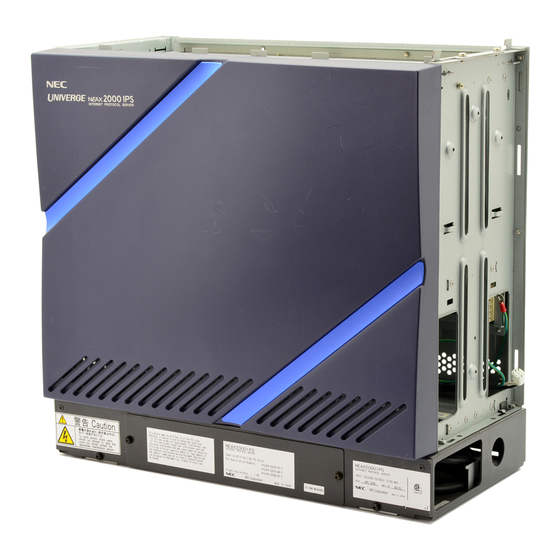
Page 38: Neax 2000 Ips
For the purpose of simplifying orders, a Base/Top ASSEM includes a Power cable for PIM 0 and Label. Chapter 3 Module and Installation Hardware QUANTITY NEAX 2000 IPS Front Cover (Blue) Left Top Cover Triangle/Name Plate Left Top Cover Triangle/Name Plate One per Stack…
-
Page 39: Figure 3-3 Floor-Standing Installation
Chapter 3 Module and Installation Hardware Installation Hardware TOP COVER COVER PARTS BASE Figure 3-3 Floor-standing Installation NEAX 2000 IPS Configuration Guide Page 29 NDA-24347, Issue 1…
-
Page 40: Figure 3-4 Wall-Mounting Installation
Installation Hardware Chapter 3 Module and Installation Hardware HANGER ASSEM HOOK HOOK BASE SCREWS FRONT Figure 3-4 Wall-mounting Installation NEAX 2000 IPS Configuration Guide Page 30 NDA-24347, Issue 1…
-
Page 41: Figure 3-5 19-Inch Rack-Mounting Installation (Bracket A)
Chapter 3 Module and Installation Hardware Installation Hardware Figure 3-5 19-inch Rack-mounting Installation (Bracket A) NEAX 2000 IPS Configuration Guide Page 31 NDA-24347, Issue 1…
-
Page 42: Figure 3-6 19-Inch Rack-Mounting Installation (Bracket B)
Installation Hardware Chapter 3 Module and Installation Hardware BASE PLATE Figure 3-6 19-inch Rack-mounting Installation (Bracket B) NEAX 2000 IPS Configuration Guide Page 32 NDA-24347, Issue 1…
-
Page 43: Figure 3-7 Mounting Bracket
Chapter 3 Module and Installation Hardware Installation Hardware FRONT SCREWS MOUNTING BRACKET Figure 3-7 Mounting Bracket NEAX 2000 IPS Configuration Guide Page 33 NDA-24347, Issue 1…
-
Page 44: Figure 3-8 I/F Bracket
Installation Hardware Chapter 3 Module and Installation Hardware FRONT SIDE SCREW PIM 3 PIM 7 SCREW I/F BRACKET Figure 3-8 I/F Bracket NEAX 2000 IPS Configuration Guide Page 34 NDA-24347, Issue 1…
-
Page 45: Figure 3-9 Base Tray Assembly
Chapter 3 Module and Installation Hardware Installation Hardware BASE TRAY Figure 3-9 Base Tray Assembly NEAX 2000 IPS Configuration Guide Page 35 NDA-24347, Issue 1…
-
Page 46
This page is for your notes. NEAX 2000 IPS Configuration Guide Page 36 NDA-24347, Issue 1… -
Page 47: Chapter 4 Circuit Cards
Chapter 4 Circuit Cards NEAX 2000 IPS Circuit Cards NEAX 2000 IPS circuit cards are divided into the following three types. According to these card types, the mounting location of the card and port allocation of the Time Division Switch varies.
-
Page 48: Table 4-1 Location Of Cards
<If two IP PADs are used> Chapter 4 Circuit Cards TYPE OF CARD MOUNTED LT or AP PIM 0: MP PIM 2, 4, 6: FP PIM 1, 3, 5, 7: Not Used AP cards can be mounted NEAX 2000 IPS Configuration Guide NDA-24347, Issue 1…
-
Page 49
Chapter 4 Circuit Cards Note 2: PIM 0 PIM 1 — 7 NEAX 2000 IPS Configuration Guide NDA-24347, Issue 1 IP Trunk The Voice CODEC card (VCT) needs to be next to the IP Trunk card (IPT) or other VCT card due to cable length. -
Page 50
Installation cable is inserted from BWB Chapter 4 Circuit Cards For the first two circuits, the installation cable is inserted from BWB. For the last two circuits, the cable is inserted from front side via connector. NEAX 2000 IPS Configuration Guide NDA-24347, Issue 1… -
Page 51: Common Control Cards
Chapter 4 Circuit Cards Common Control Cards Table 4-2 shows a summary of the common control cards for NEAX 2000 IPS. Table 4-2 ABBR. NAME CODE SPN-CP24A MP (UA) PN-CP24-A SP-3499 IXS KUL PROG-A1 SP-3643 IPS DTG-A1 IL-C2-1-0001 CONTACT ETHER…
-
Page 52: Main Processor (Mp)
16 sets of 3-way conference circuitry 32 circuits (digit 0 to 9, *, and # are generated) Two types are available (Melody or External Source) Two ports (Source/Receiver) Four circuits NEAX 2000 IPS Configuration Guide NDA-24347, Issue 1 Note 1 Note 2…
-
Page 53: Figure 4-2 Port Allocation Of Time Division Switch
Chapter 4 Circuit Cards NEAX 2000 IPS Configuration Guide NDA-24347, Issue 1 64 Ports 128 Ports/FP 64 Ports 64 Ports 128 Ports/FP 64 Ports 64 Ports 128 Ports/FP 64 Ports 64 Ports 128 Ports/FP 64 Ports 128 Ports 128 Ports…
-
Page 54: Firmware Processor (Fp)
This card provides Ethernet interface between MP and LAN for call control of Dterm Ethernet Card IP telephones/CCIS over IP with another NEAX 2000 IPS/2400 IPX. It also provides interface for MATWorX and the OAI/ACD server. The FP provides supervision and status analysis of Line/Trunk ports, which reside in Firmware the PIM.
-
Page 55: Line/Trunk (Lt) Cards
Chapter 4 Circuit Cards Line/Trunk (LT) Cards Table 4-3 shows a summary of the Line/Trunk (LT) cards for NEAX 2000 IPS. The LT cards may be installed in Slot 00 to 11 of PIM 0-7, with the following conditions: •…
-
Page 56: Figure 6-6
• For Caller ID (for SLT) • Maximum of four per system. 6-/10-Party Conference Trunk with Amp 150120 • 6-party (one CFTB card): 10 ports • 10-party (two CFTB cards): 20 ports Chapter 4 Circuit Cards REMARKS NEAX 2000 IPS Configuration Guide NDA-24347, Issue 1…
-
Page 57
SPN-2CSIA SP-3174 BSI PROG-A SPN-2CSIH SP-3174 BSI PROG-A Optical PN-M10 Modem DK00 PN-DK00 NEAX 2000 IPS Configuration Guide NDA-24347, Issue 1 Line/Trunk (LT) Cards (Continued) PART PORT NUMBER 4-circuit Digital Announcement Trunk 150015 • Maximum of 120 seconds each. 151210… -
Page 58
• One V35 Interface per card NEAXMail AD-8 with Modem 151113 • Uses four LT Time Slots 4-port Expansion 151272 • For NEAXMail AD-8 • Uses an additional four LT Time Slots Chapter 4 Circuit Cards REMARKS NEAX 2000 IPS Configuration Guide NDA-24347, Issue 1… -
Page 59: Application Processor (Ap) Cards
Chapter 4 Circuit Cards Application Processor (AP) Cards The following table shows a summary of the Application Processor cards for NEAX 2000 IPS ABBR. NAME CODE SPN-24DTAC-B (AP) SC-3015 IXS PRT PROG-C1 SPN-30DTC-UA (AP) SC-2694 SHS DTC PROG-CB SP-3395 SHS PAD PROG-A…
-
Page 60
VCT per card, maximum 16 channels per card) system /NEAX 2400 IMX (without Peer-to-Peer connection) (In case of G.729a payload 40 milliseconds: three VCT per card, maximum 12 channels per card) system NEAX 2000 IPS Configuration Guide NDA-24347, Issue 1… -
Page 61
The AP cards may be installed in Slot 00 to 11 of PIM 0-7, with the following conditions: Note: • Maximum 24 cards per system • Maximum 256 ports per system NEAX 2000 IPS Configuration Guide NDA-24347, Issue 1 Application Processor (AP) Cards (Continued) PART… -
Page 62
This page is for your notes. NEAX 2000 IPS Configuration Guide Page 52 NDA-24347, Issue 1… -
Page 63: Chapter 5 System Power Supply
The DC/DC Power card is mounted under the AC/DC Power card and generates -48 V power, which is used to power ancillary devices such as Wireless and Analog Caller ID stations. ABBR. NEAX 2000 IPS Configuration Guide NDA-24347, Issue 1 Table 5-1 AC/DC Power Card…
-
Page 64: Battery Backup
Figure 5-1 Table 5-3 NAME PART CODE NUMBER PZ-8PFTB 150119 Chapter 5 System Power Supply CHAMP CONNECTOR ATTACHED TO PZ-8PFTB 25-PAIR CABLE TO MDF PZ-8PFTB Installation PZ-8PFTB REMARKS 8-line PFT Card per PIM NEAX 2000 IPS Configuration Guide NDA-24347, Issue 1…
-
Page 65: Chapter 6 Cabling
Chapter 6 Cabling The internal and external cabling of the NEAX 2000 IPS is as follows: • Internal Cabling • • • • • External Cabling • • • • • • • • • NEAX 2000 IPS Configuration Guide…
-
Page 66: Internal Cabling
Figure 6-1 BUS Cable Connection Table 6-1 NAME CODE 48-TW-0.7 CONN CA Chapter 6 Cabling PIM 7 PIM 6 PIM 5 PIM 4 BUS Cable PART REMARKS NUMBER 151013 2.3 ft. (0.7 m) NEAX 2000 IPS Configuration Guide NDA-24347, Issue 1…
-
Page 67: Power Control Cable
The DC power cable provides a connection between the AC/DC power supply for DC Power Cable extending the 27 VDC input in a multiple-PIM configuration, when battery backup option is required. An Internal Battery is installed in every PIM. NEAX 2000 IPS Configuration Guide NDA-24347, Issue 1 Table 6-2 PART NAME CODE…
-
Page 68: Figure 6-3 Power Cable Connection (External Battery Option)
Chapter 6 Cabling REMARKS DC Power Cable (-27 V input) Internal Battery Cable PIM 7 PIM 6 PIM 5 PIM 4 To Battery REMARKS DC Power Cable (-27 V input) External Battery Cable NEAX 2000 IPS Configuration Guide NDA-24347, Issue 1…
-
Page 69: Ac Cord
Chapter 6 Cabling The AC cord provides a connection between the AC/DC power card and base unit. AC Cord Base Unit SYMBOL NEAX 2000 IPS Configuration Guide NDA-24347, Issue 1 PIM 3 PIM 2 PIM 2 PIM 0 To Base Unit…
-
Page 70: External Cabling
OAI Server (Maximum of four) CCIS over IP via IP Network (Linked with distant NEAX 2000 IPS) REMARKS IP TRK BUS Cable • 0.33 ft. (0.1 m) (Included in SPN-16VCTA IP PAD) NEAX 2000 IPS Configuration Guide NDA-24347, Issue 1…
-
Page 71: Table 6-7 Ip Bus Cable (Ipt)
Chapter 6 Cabling IP Trunk (H.323, CCIS over IP with NEAX 2000 IVS NAME CODE IP TRK BUS CA NEAX 2000 IPS Configuration Guide NDA-24347, Issue 1 10 BASE-T/100 BASE-TX (Local Supply) 4VCT IP TRK BUS CA 4VCT Figure 6-6…
-
Page 72: Attendant Console
LTC 0 LTC 3 Installation Cable with 8DLCP: Maximum 984 ft. (300 m) with 4DLCM/4DLCQ/2DLCN: Maximum 3937 ft. (1200 m) Figure 6-7 Attendant Console Cable Connection Chapter 6 Cabling SN716 DESKCON SN716 DESKCON NEAX 2000 IPS Configuration Guide NDA-24347, Issue 1…
-
Page 73: Maintenance Administration Terminal (Mat) (Rs-232C)
Direct Connection Maintenance Administration Terminal (MAT) (RS-232C) MAT CA-T MAT CA-P NEAX 2000 IPS Configuration Guide NDA-24347, Issue 1 RS 1 RS 0 MAT CA-P 13.0 ft. (4 m) MAT CA-T 6.5 ft. (2 m) Figure 6-8 MAT Cable Connection (Direct)
-
Page 74: Figure 6-9 Mat Cable Connection (Remote Connection Via Internal Modem)
MAT Cable (Remote Connection via External Modem) NAME CODE PART NUMBER 151004 Chapter 6 Cabling Installation Cable MODEM PSTN 25p DSUM (M) MODEM PSTN MODEM REMARKS RS-232C Cable, 13.1 ft. (4 m) NEAX 2000 IPS Configuration Guide NDA-24347, Issue 1…
-
Page 75: Built-In Smdr/Mci On Mp
Number 0/1 Port: Asynchronous: 1200/2400/4800/9600/19200 bps Connection to SMDR is made on a port basis by a front cable. RS RVS-4S CA-C RS NORM-4S CA-A NEAX 2000 IPS Configuration Guide NDA-24347, Issue 1 RS 0 RS 1 RS RVS-4 CA-C…
-
Page 76: Smdr (With Ap00)/Pms/Hotel Printer/Mci/Ccis Centralized Smdr
25p DSUB (M) REMARKS RS-232C Cable, 13.1 ft. (4 m) PN-AP00 — DTE RS-232C Cable, 13.1 ft. (4 m) PN-AP00 — DCE (MODEM) RS-232C Cable, 49.2 ft. (15 m) PN-AP00 — Printer NEAX 2000 IPS Configuration Guide NDA-24347, Issue 1…
-
Page 77: External Alarm Display
Chapter 6 Cabling The NEAX 2000 IPS can provide an optional external alarm display unit (ALM External Alarm DSPP) to indicate Power-ON/OFF, Major Alarm, and Minor Alarm status. Display NEAX 2000 IPS Configuration Guide NDA-24347, Issue 1 Slot 13 LTC0…
-
Page 78: Digital Trunk Interface (Dti)/Primary Rate Interface (Pri)/Ccis Trunk Interface (Cct)
Slot 00 to 11 LTC 1 LTC 3 LTC 0 LTC 2 Installation Cable Installation Cable (Twisted-pair Cable) (Twisted-pair cable) Figure 6-14 DTI Cable Connection (Twisted-pair Cable) Chapter 6 Cabling MUX . Digital Network NEAX 2000 IPS Configuration Guide NDA-24347, Issue 1…
-
Page 79: Data Port Controller (Dpc)
Controller (DPC) V.11/X21 Interface (Asynchronous/Synchronous: 600 ~ 64 kbps) DPC V11 CA DPC RS CA NEAX 2000 IPS Configuration Guide NDA-24347, Issue 1 V.11/X21 Interface (Asynchronous/Synchronous: 600 — 64 kbps) Slot 00 to 11 DPC V11 CA 13.1 ft.
-
Page 80: Dpc And X.21/V.35 Converter
17-TW-0.3 CONN CA-A 1 ft. (0.3 m) DPC V35 CA 13.1 ft. (4 m) REMARKS Data Port Controller V.11 (X.21) • For 56 kbps (Synchronous) • Distance (PN-2DPCB-DTE): 3,280.8 ft. (1,000 m) V35 Interface Card NEAX 2000 IPS Configuration Guide NDA-24347, Issue 1…
-
Page 81: Chapter 7 Dterm Ip
When the data server (such as System-based DRS, Network-based DRS on the LAN, DHCP Server and FTP/TFTP Server) is used, the Dterm IP must be connected to the LAN that accommodates the servers. Connect the Dterm IP to the LAN before you follow the procedure below.
-
Page 82: Table 7-1 User Menu Items
Enter the Subnet Mask. • When the DHCP server gives the Subnet Mask, or when no Subnet Mask is required, this setting is not required. NEAX 2000 IPS Configuration Guide NDA-24347, Issue 1…
-
Page 83
Priority Number 0-7 System Information For the IP Address of the DNS server, ask the network administrator. Only VLAN tag is available. Do not set the VLAN ID Number 0 and 1. Menu items. To display Administrator Menu, stay in the User Menu and press Hold, #, 0 keys in that order. -
Page 84
DRS System-based. Note 1 Note 2 No setting is required. Enter the DRS Self-port number. Note 1 LM Self-port setting is not required. Enter the DRS Self-port number. Note 1 NEAX 2000 IPS Configuration Guide NDA-24347, Issue 1… -
Page 85
To operate the Dterm IP normally, you must not change the port number, which has been set except when the port number needs to be changed. For the port number of the DRS System-based, ask the NEAX 2000 IPS maintenance person. -
Page 86: Dterm Ip Login/Logout
Dterm IP Display (ID Registration without Password) After the first registration, Login operation is not required. Figure 7-2 Dterm IP Display (ID Registration with Password) Chapter 7 Dterm IP S e t NEAX 2000 IPS Configuration Guide NDA-24347, Issue 1…
-
Page 87: Dterm Ip Logout
STEP 1: Go off-hook or press Speaker key. Dterm IP Logout STEP 2: Enter the logout access code assigned by CM20 or press the logout key NEAX 2000 IPS Configuration Guide NDA-24347, Issue 1 Time and date appears on the LCD.
-
Page 88
This page is for your notes. NEAX 2000 IPS Configuration Guide Page 78 NDA-24347, Issue 1… -
Page 89: Chapter 8 System Capacity
Central Office Trunk (Lines) Tie Line Trunk (Lines) CCIS Trunk (Peer-to-Peer Connection) DTI/CCIS Digital Link Note 1 NEAX 2000 IPS Configuration Guide NDA-24347, Issue 1 Table 8-1 Main Processor (MP) System SYSTEM CAPACITY 1 PIM 2 PIM 3 PIM 4 PIM 5 PIM 6 PIM 7 PIM 8 PIM…
-
Page 90
Maximum one interface port per system Maximum one interface port per system Chapter 8 System Capacity Note Note 2 Maximum 32 circuits per system Maximum eight sets per system 1,000 3,000 1,024 10,000 1,280 NEAX 2000 IPS Configuration Guide NDA-24347, Issue 1… -
Page 91
20 ms 30 ms 40 ms VoIP (H.323) PAYLOAD SIZE 20 ms 30 ms 40 ms ACD/MIS and OAI are mutually exclusive. Note 5: NEAX 2000 IPS Configuration Guide NDA-24347, Issue 1 G.729a G.711 8-Channel 8-Channel 16-Channel 16-Channel 16-Channel 16-Channel G.729a… -
Page 92: Floor-Standing Installation Equipment
Page 82 1 PIM 2 PIM 3 PIM 4 PIM 5 PIM 6 PIM 7 PIM 8 PIM INTERNAL BATT EXTERNAL BATT Chapter 8 System Capacity NEAX 2000 IPS Configuration Guide NDA-24347, Issue 1…
-
Page 93: Lt/Ap Card Slots
When the system is comprised of more than two PIMs, vacant slots exist in Slot 12 (MP Slot) of PIM 1, 3, Note 3: 5, and 7. NEAX 2000 IPS Configuration Guide NDA-24347, Issue 1 Number of Slots for LT/AP Cards of each PIM…
-
Page 94: Line Conditions
3,937 ft. (1,200 m) 3,937 ft. (1,200 m) Same as Dterm Series E 984 ft. (300 m) Note 3 1,148 ft. (350 m) 3,937 ft. (1,200 m) 1,148 ft. (350 m) 3,937 ft. (1,200 m) NEAX 2000 IPS Configuration Guide NDA-24347, Issue 1…
-
Page 95: Zone Transceiver Line Conditions
Zone Transceiver requires -48 V power under normal conditions. PBX power supply at -45 V and -43 V Note: shows ZT Line Conditions in the event of lower voltage status (refer to NEAX 2000 IPS Configuration Guide NDA-24347, Issue 1 Zone Transceiver Line Conditions…
-
Page 96: Traffic Capacity
TCP PORT NUMBER Chapter 8 System Capacity 5 PIM 6 PIM 7 PIM Maximum Maximum 7,500 BHCA 8,000 BHCA Note Note REMARKS Use blank as a password 60000 (Fixed) 60030 (Fixed) NEAX 2000 IPS Configuration Guide NDA-24347, Issue 1 8 PIM…