
-
Contents
-
Table of Contents
-
Troubleshooting
-
Bookmarks
Quick Links
Power for the Digital Revolution
AVR 130
AUDIO/VIDEO RECEIVER
OWNER’S MANUAL
DIGITAL
LOGIC 7
PRO LOGIC
3 STEREO
DSP
5 CH. STEREO
SURR. OFF
Surr. Select
®
®
.
VID 1
DVD
VID 2
CD
VID 3
FMAM
TAPE
6 CH
Coaxial
Related Manuals for Harman Kardon AVR 130
Summary of Contents for Harman Kardon AVR 130
-
Page 1
Power for the Digital Revolution AVR 130 AUDIO/VIDEO RECEIVER OWNER’S MANUAL DIGITAL LOGIC 7 PRO LOGIC 3 STEREO 5 CH. STEREO SURR. OFF Surr. Select ® ® VID 1 VID 2 VID 3 FMAM TAPE 6 CH Coaxial… -
Page 2: Table Of Contents
AVR 130 AUDIO/ VIDEO RECEIVER Introduction Safety Information Unpacking Front-Panel Controls Rear-Panel Connections Remote Control Functions Installation and Connections System Installation Audio Equipment Connections Video Equipment Connections Power Connections System Configuration Speaker Selection and Placement System Setup Speaker Setup Triple Crossover Setting…
-
Page 3: Introduction
DVD releases and Digital Television broadcasts. While complex digital systems are hard at work within the AVR 130 to make all of this happen, hookup and operation are simple. Color-keyed connections and a programmable remote control make the AVR 130 easy to use.
-
Page 4: Safety Information
SAFETY INFORMATION Important Safety Information Verify Line Voltage Before Use Your AVR 130 has been designed for use with 120- volt AC current. Connection to a line voltage other than that for which it is intended can create a safety and fire hazard and may damage the unit.
-
Page 5: Front-Panel Controls
Ô Video 3 Video Input Jacks Video 3 Audio Input Jacks AVR 130; press it again to turn the unit off. The Power Indicator 3 turns blue when the unit is on. 4 Headphone Jack: This jack may be used to listen to the AVR 130’s output through a pair of headphones.
-
Page 6
26.) Ù Volume Control: Turn this knob clockwise to increase the volume, counterclockwise to decrease the volume. If the AVR 130 is muted, adjusting the Volume Control Ù will automatically release the unit from the silenced condition. -
Page 7: Rear-Panel Connections
¡ ™ £ ¢ ¡ CD Audio Inputs ™ Tape Outputs £ Tape Inputs ¢ Subwoofer Output ∞ Front Speaker Outputs § Surround Speaker Outputs ¶ Center Speaker Outputs • Optical Digital Inputs ª Coaxial Digital Inputs NOTE: To make it easier to follow the instructions that refer to this illustration, a larger copy may be downloaded from the Product Support section for this product at www.harmankardon.com.
-
Page 8
⁄ Switched AC Accessory Outlet: This outlet may be used to power any device you wish to have turned on or off at the same time as the AVR 130. Any device connected to this outlet will be off when the AVR 130 is in the Standby mode, and power will be supplied to the outlet when the AVR 130 is turned on. -
Page 9: Remote Control Functions
6-Channel Direct Input Button Mute NOTES: • The function names shown here refer to each button’s feature when used with the AVR 130. Most buttons have additional functions when used with other devices. See pages 31–32 for a list of these functions.
-
Page 10: Remote Control Functions
AVR Selector: Pressing this button will switch the remote so that it will operate the AVR 130’s functions. If the AVR 130 is in the Standby mode, it will also turn the AVR 130 on. g AM/FM Tuner Select: Press this button to select the AVR 130’s tuner as the listening choice.
-
Page 11
` Transport Controls: These buttons do not have any functions for the AVR 130, but they may be pro- grammed for the forward/ reverse play operation of a wide variety of CD or DVD players, and audio or video cassette recorders. -
Page 12
Direct Input a as the audio source. Mute: Press this button to momentarily silence the AVR 130 or TV set being controlled, depending on which device has been selected. When the AVR 130 is muted, press this button or use the Volume Control Ù… -
Page 13: Installation And Connections
CD or LD player’s PCM (S/P-DIF) output. 4. Connect the Optical Digital Output ‹ or Coaxial Digital Output › on the rear panel of the AVR 130 to the matching digital input connections on a CD-R or MiniDisc recorder.
-
Page 14: Power Connections
S-Video, or vice versa. S-Video inputs may only be viewed when the AVR 130 is connected to a TV set or video display with S-Video capability. If you use both standard composite video and S-Video sources in your…
-
Page 15: System Configuration
You are now ready to power up the AVR 130 to begin these final adjustments. 1. Plug the Power Cord ‚ into an unswitched AC outlet.
-
Page 16: System Setup
SYSTEM CONFIGURATION 5. Turn the AVR 130 on either by pressing the System Power Control 3 on the front panel, or via the remote by pressing the AVR Selector f or any of the Input Selectors eg on the remote. The Power Indicator 3 will turn blue to confirm that the unit is on, and the front- panel display will illuminate.
-
Page 17: Triple Crossover Setting
“main” speakers. • If a subwoofer is connected to the AVR 130, you have the option to have the front left/right “main” speakers reproduce bass frequencies at all times, and have the subwoofer operate only when the…
-
Page 18: Output Level Adjustment
SURROUND OFF appears in the Lower Display Line ¯ and the Surround Mode Indicator ˘ for Surr Off is lit, the AVR 130 will pass the analog source material directly through to the front left and right speakers, bypassing the digital-processing circuitry.
-
Page 19: Delay Settings
The AVR 130’s advanced software enables you to quickly and easily set delay times without using a complex formula to calculate them. Instead, all you…
-
Page 20
Once the settings outlined on the previous pages have been made, the AVR 130 is ready for operation. There are some additional settings that may be made if desired, but these are best done after you have had an opportunity to listen to a variety of sources and dif- ferent kinds of program material. -
Page 21: Operation
Bass Control Ó and Treble Control Ú to suit your listening tastes or room acoustics. • To set the output of the AVR 130 so that the output is “flat, ” with the tone controls deactivated, press the Tone Mode Button 5 until the words Tone Out appear momentarily in the Lower Display Line ¯.
-
Page 22: Surround Mode Chart
The Surround Off (Bypass) mode may only be used with analog source DSP Surround Off inputs, as it preserves the analog format of the audio signal for its entire path of travel through the receiver to the speaker and subwoofer outputs, bypassing all digital processing. Digital bass management is not available in Surround Off mode.
-
Page 23: Surround Mode Selection
DTS discs. You may use any LD or CD player equipped with a digital output to play DTS-encoded discs with the AVR 130. All that is required is to con- nect the player’s output to either the Optical or Coaxial input on the rear panel •ª or front panel…
-
Page 24: Night Mode
DVD player (usually with the “Audio Select” button or in a menu screen on the disc) to send a full 5.1 feed to the AVR 130. It is also pos- sible for the type of signal feed to change during the course of a DVD playback.
-
Page 25: Tuner Operation
7 M or Music mode for a wider soundstage and increased rear-channel ambience. Tuner Operation The AVR 130’s tuner is capable of tuning AM, FM and FM Stereo broadcast stations. Stations may be tuned manually, or they may be stored as favorite station pre- sets and recalled from a 30-position memory.
-
Page 26: Output Level Trim Adjustment
OPERATION Output Level Trim Adjustment Normal output level adjustment for the AVR 130 is established using the test tone, as outlined on pages 18 and 19. In some cases, however, it may be desir- able to adjust the output levels using program material such as a test disc, or a selection you are familiar with.
-
Page 27: Programming The Remote
Auto Search Method. Auto Search Method If the unit you wish to include in the AVR 130’s remote is not listed in the code tables in this manual or if the code does not seem to operate properly, you may wish…
-
Page 28: Macro Programming
Function List and then look in the column for the device you are controlling. For example, button num- ber 51 is the Macro 2 button for the AVR 130, but it is the “Favorite” button for many cable television boxes and satellite receivers.
-
Page 29: Volume Punch-Through
TV viewing, you may wish to have the AVR 130’s volume activated, although the remote is set to run the TV. Either the AVR 130 or TV volume control may be associated with any of the remote’s devices.
-
Page 30
Do not confuse these numbers with those used throughout the rest of this manual to indicate the specific buttons used to operate the AVR 130’s functions. The key to those button numbers, which are shown inside an oval, is found on page 9. -
Page 31: Function List
No. Button Name AVR Function Power On Power On Power On Power Off Power Off Power Off Mute Mute Mute AVR Select DVD Input Select DVD Select CD Input Select Tape Tape Input Select VID1 Video 1 Select VID2 Video 2 Select 10 VID3 Video 3 Select 11 Dim…
-
Page 32
FUNCTION LIST No. Button Name AVR Function 44 Direct Direct Tuner Entry 45 Clear Clear Clear 46 Preset Up Preset Tune Up Slow Forward 47 Tune Down Tune Down Prev Chapter 48 D. Skip Disc Skip 49 Preset Down Preset Tune Down Slow Rev 50 M1 Open/Close… -
Page 33: Setup Code Tables
CONTEC CORANDO CORONADO CRAIG CROWN CURTIS MATHES DAEWOO DAYTRON DIGI LINK DYNASTY DYNATECH ELECTROHOME EMERSON FUNAI FUTURETECH GOLD STAR/LG GRUNDIG HALL MARK HARMAN KARDON HITACHI INFINITY INKEL JC PENNEY JENSEN KAWASHO KENWOOD LLOYTRON LODGENET SETUP CODE TABLE: TV SETUP CODES…
-
Page 34
SETUP CODE TABLE: TV Manufacturer/Brand Setup Code Number LOGIK LUXMAN MAGNAVOX MARANTZ MATSUI MEMOREX METZ MINERVA MITSUBISHI NATIONAL NIKEI ONKING ONWA OPTONICA ORION PANASONIC PHILCO PHILIPS PIONEER PORTLAND PROSCAN PROTON QUASAR RADIO SHACK REALISTIC RUNCO SAMPO SAMSUNG SANYO SCOTT SEARS SHARP SIEMENS SIGNATURE… -
Page 35
018 048 DYNATECH EMERSON 013 040 042 110 112 FISHER FUNAI 076 095 124 GO VIDEO GOLD STAR/LG 018 107 HARMAN KARDON 018 049 HITACHI 040 048 JC PENNEY 018 045 JENSEN 018 048 111 132 KENWOOD 020 048 LLOYD… -
Page 36
SETUP CODE TABLE: VCR Manufacturer/Brand Setup Code Number MARANTZ MEMOREX 017 020 040 052 053 054 076 MITSUBISHI 049 131 MULTITECH NATIONAL 018 048 NORDMENDE OPTIMUS ORION PANASONIC 125 150 167 172 PHILCO PHILIPS 040 075 PORTLAND PULSAR QUASAR 001 125 RADIO SHACK 055 134 140 142 158 159 095 124 125 157 172… -
Page 37
AUDIOFILE CALIFORNIA AUDIO CAPETRONIC CARRERA CARVER 143 144 CASIO CLARINETTE DENON EMERSON FISHER FRABA FUNAI GENEXXA GOLD STAR/LG HAITAI HARMAN KARDON 054 190 HITACHI INKEL JC PENNEY JENSEN KENWOOD 079 148 LOTTE LUXMAN MAGNAVOX MARANTZ 192 193 MCINTOSH MITSUMI MODULAIRE… -
Page 38
WARDS YAMAHA YORK SETUP CODE TABLE: DVD Manufacturer/Brand Setup Code Number APEX DIGITAL DENON 019 051 003 004 GOLD STAR/LG HARMAN KARDON 005 055 064 066 MAGNAVOX MARANTZ MITSUBISHI ONKYO 009 048 PANASONIC 024 030 044 PHILIPS PIONEER 041 065… -
Page 39
Manufacturer/Brand Setup Code Number ALPHASTAR ALPHASTAR DBS ALPHASTAR DSR BIRDVIEW CHANNEL MASTER 320 321 CHAPARRAL 315 316 CITOH DRAKE 313 317 413 481 DX ANTENNA 331 352 379 483 ECHOSTAR 395 397 453 463 ELECTRO HOME FUJITSU 324 329 GENERAL INSTRUMENT 303 311 365 403 HITACHI DBS… -
Page 40
SETUP CODE TABLE: TAPE/CBL Manufacturer/Brand Setup Code Number HARMAN KARDON SETUP CODE TABLE: CBL Manufacturer/Brand Setup Code Number 001 011 ALLEGRO AMERICAST ARCHER BELCOR CABLE STAR 033 113 CITIZEN COLOUR VOICE 085 090 DIGI EAGLE EASTERN 066 070 ELECTRICORD EMERSON FOCUS G.I. -
Page 41
Manufacturer/Brand Setup Code Number REMBRANT SAMSUNG 072 186 SCIENTIFIC ATLANTA 183 203 221 222 SEAM SIGNATURE 001 188 SPRUCER 053 081 177 189 STARCOM 002 011 163 STARGATE TANDY TELECAPATION TEXSCAN TIMELESS TOCOM 170 205 UNITED CABLE UNIVERSAL 033 034 039 042 113 VIDEOWAY 124 211 VIEWSTAR… -
Page 42: Troubleshooting Guide
Your AVR 130 receiver has been designed to provide many years of trouble-free service. In the event that you are experiencing difficulties, please check the suggestions below for a possible solution to your problem. Additional information on the AVR 130, including updated information and user hints, is available from our Web site at www.harmankardon.com.
-
Page 43: Specifications
Height measurement includes feet and chassis. All features and specifications are subject to change without notice. Harman Kardon, Power for the Digital Revolution and Logic 7 are registered trademarks of Harman International Industries, Incorporated. * Manufactured under license from Dolby Laboratories. “Dolby, ” “Pro Logic” and the Double-D symbol are registered trademarks of Dolby Laboratories.
-
Page 44
® 250 Crossways Park Drive, Woodbury, New York 11797 www.harmankardon.com © 2003 Harman International Industries, Incorporated Part No. CQX1A849Z…
DIGITAL LOGIC 7
VID 1
DVD
CD
FMAM
TAPE
6 CH
VID 2
VID 3
PRO LOGIC
3 STEREO DSP
5 CH. STEREO
SURR. OFF
Surr. Select
Coaxial
AVR 130
AUDIO/VIDEO RECEIVER
OWNER’S MANUAL
®
Power for the Digital Revolution.
®

Typographical Conventions
In order to help you use this manual with the remote control, front-panel controls and rear-panel connections,
certain conventions have been used.
EXAMPLE – (bold type) indicates a specific remote control or front-panel button, or rear-panel
connection jack
EXAMPLE – (OCR type) indicates a message that is visible on the front-panel information display
1 – (number in a square) indicates a specific front-panel control
¡ – (number in a circle) indicates a rear-panel connection
a – (number in an oval) indicates a button or indicator on the remote
2 TABLE OF CONTENTS
3 Introduction
4 Safety Information
4 Unpacking
5 Front-Panel Controls
7 Rear-Panel Connections
9 Remote Control Functions
13 Installation and Connections
13 System Installation
13 Audio Equipment Connections
13 Video Equipment Connections
14 Power Connections
15 System Configuration
15 Speaker Selection and Placement
16 System Setup
16 Speaker Setup
17 Triple Crossover Setting
17 Global/Independent Bass Manager Memory
17 Configuring the Surround Off (Stereo) Modes
18 Output Level Adjustment
19 Delay Settings
19 Additional Input Adjustments
21 Operation
21 Basic Operation
21 Source Selection
21 Volume Control
22 Surround Mode Chart
23 Surround Mode Selection
23 Digital Audio Playback
23 Selecting a Digital Source
24 Digital Bitstream Indications
25 Night Mode
25 Tuner Operation
25 Tape Recording
26 Output Level Trim Adjustment
26 6-Channel Direct Input
26 Display Brightness
27 Programming the Remote
27 Direct Code Entry
27 Auto Search Method
27 Code Readout
28 Macro Programming
28 Programmed Device Functions
28 Punch-Through Programming
29 Volume Punch-Through
29 Channel Control Punch-Through
29 Transport Control Punch-Through
29 Resetting the Remote Memory
31 Function List
33 Setup Code Tables
42 Troubleshooting Guide
42 Processor Reset
43 Technical Specifications
43 Trademark Acknowledgements
AVR 130 AUDIO/VIDEO RECEIVER
INTRODUCTION 3
INTRODUCTION
Thank you for choosing Harman Kardon®! With
the purchase of a Harman Kardon AVR 130 you are
about to begin many years of listening enjoyment.The
AVR 130 has been custom-designed to provide all the
excitement and detail of movie soundtracks and every
nuance of musical selections.Dolby
* Digital and DTS
®
decoding allows you to take advantage of digital
soundtracks from the latest DVD releases and Digital
Television broadcasts.
While complex digital systems are hard at work within
the AVR 130 to make all of this happen,hookup and
operation are simple.Color-keyed connections and a
programmable remote control make the AVR 130
easy to use.To obtain the maximum enjoyment from
your new receiver, we urge you to take a few minutes
to read through this manual.This will ensure that connections to speakers,source playback units and other
external devices are made properly.In addition, a few
minutes spent learning the functions of the various
controls will enable you to take advantage of all the
power the AVR 130 is able to deliver.
If you have any questions about this product, its installation or its operation, please contact your retailer or
custom installer. They are your best local sources of
information.
Description and Features
The AVR 130 is a versatile and multifeatured A/V
receiver, incorporating a wide range of listening
options.In addition to Dolby Digital and DTS decoding
for digital sources,a broad choice of analog surround
modes are available for use with sources such as CD,
VCR,TV broadcasts and the AVR 130’s own FM/AM
tuner. Along with Dolby Pro Logic
* II decoding technology,Dolby 3 Stereo and custom Hall and Theater
modes,only Harman Kardon receivers offer Logic 7
®
to create a wider, more enveloping field environment
and more defined fly-overs and pans.Another feature
exclusive to Harman Kardon receivers is VMAx,
®
which uses proprietary processing to create an
open, spacious sound field even when only two front
speakers are available.
In addition to providing a wide range of listening
options,the AVR 130 is easy to configure so that it
provides the best results with your speakers and
specific listening-room environment.A Stereo-Direct
mode bypasses the digital processor to preserve all of
the subtleties of older analog,two-channel materials,
while bass management, available in the surround
and Stereo-Digital modes,improves your ability to
tailor the sound to suit your room acoustics or taste.
For the ultimate in flexibility, the AVR 130 features
connections for four video devices,all with both composite and S-Video inputs,including the front-panel
inputs.Two additional audio inputs are available, and a
total of six digital inputs make the AVR 130 capable of
handling all the latest digital audio sources.Coax and
optical digital audio outputs are also available for direct
connection to digital recorders.A video recording
output and a six-channel input make the AVR 130
virtually future-proof, with everything needed to
accommodate tomorrow’s new formats right on board.
The AVR 130’s powerful amplifier uses traditional
Harman Kardon high-current, ultrawide bandwidth
design technologies.
Harman Kardon invented the high-fidelity receiver fifty
years ago.With state-of-the-art circuitry and timehonored circuit designs,the AVR 130 is one of the
finest receivers ever offered by Harman Kardon.
■ Onboard Dolby* Digital and DTS
®
* Decoding
Using Cirrus
®
Chip Technology
■ Harman Kardon’s Exclusive Logic 7
®
and
VMAx
®
Modes
■ Dolby Laboratories’ Pro Logic* II Processing
Technology
■ Stereo-Direct Mode for Two-Channel Sources
Bypasses DSP Processing to Preserve the
Integrity of Analog Materials
■ Stereo-Digital Mode for Programmable Bass
Management of Low Frequencies Between
Main Speakers and Subwoofer
■ Front-Panel Digital Inputs for Easy Connection
to Portable Digital Devices and Video Game
Consoles
■ Multiple Digital Inputs and Outputs
■ 6-Channel Direct Input for Use With DVD-
Audio or SACD Players and Other Products
With Internal Surround Decoders
■ Color-Coded Input, Output and Speaker
Terminals Comply With CEA Standards for
Easy Installation
CAUTION
RISK OF ELECTRIC SHOCK
DO NOT OPEN
CAUTION: To reduce the risk
of electric shock,
do not remove cover (or back).
No user-serviceable parts inside.
Refer servicing to
qualified service personnel.
The lightning flash with arrowhead symbol,
within an equilateral triangle, is intended to
alert the user to the presence of uninsulated
“dangerous voltage” within the product’s
enclosure that may be of sufficient magnitude to constitute a
risk of electric shock to persons.
The exclamation point within an equilateral
triangle is intended to alert the user to the
presence of important operating and
maintenance (servicing) instructions in the
literature accompanying the appliance.
TO THE USER
This equipment has been tested and found to comply with the limits for a Class B digital device,pursuant to Part 15 of the FCC Rules.These limits are
designed to provide reasonable protection against
interference in a residential area.This device generates and uses radio frequency energy and if not
installed and used in accordance with the instructions,it may cause interference to radio or TV
reception.
If this unit does cause interference with TV or radio
reception, you can try to correct the interference by
one or more of the following measures:
A. Reorient or relocate the receiving antenna.
B. Increase the separation between the equipment
and the receiver.
C. Plug the equipment into a different outlet so that
it is not on the same circuit as the receiver.
If necessary,consult the dealer or an experienced
radio/TV technician for additional suggestions.
CAUTION:
Changes or modifications to this equipment not
expressly approved by
Harman Consumer Group
for compliance could void the user’s authority to
operate this equipment.
CORDE DE CONNEXION CA ATTENTION:
POUR ÉVITER LES CHOCS ÉLECTRIQUES,INTRODUIRE LA LAME LA PLUS LARGE DE LA FICHE
DANS LA BORNE CORRESPONDANTE DE LA PRISE
ET POUSSER JUSQU’AU FOND.
AC POWER CORD CONNECTION CAUTION:
TO PREVENT ELECTRIC SHOCK, MATCH WIDE
BLADE OF PLUG TO WIDE SLOT, FULLY INSERT.
For CANADA
Pour le CANADA

4 SAFETY INFORMATION
SAFETY INFORMATION
Important Safety Information
Verify Line Voltage Before Use
Your AVR 130 has been designed for use with 120volt AC current.Connection to a line voltage other than
that for which it is intended can create a safety and
fire hazard and may damage the unit.
If you have any questions about the voltage requirements
for your specific model, or about the line voltage in your
area, contact your selling dealer before plugging the unit
into a wall outlet.
Do Not Use Extension Cords
To avoid safety hazards, use only the power cord
attached to your unit.We do not recommend that
extension cords be used with this product.As with all
electrical devices,do not run power cords under rugs
or carpets or place heavy objects on them. Damaged
power cords should be immediately replaced by an
authorized service center with a cord meeting factory
specifications.
Handle the AC Power Cord Gently
When disconnecting the power cord from an AC outlet, always pull the plug,never pull the cord. If you do
not intend to use the unit for any considerable length
of time,disconnect the plug from the AC outlet.
Do Not Open the Cabinet
There are no user-serviceable components inside this
product. Opening the cabinet may present a shock
hazard, and any modification to the product will void
your guarantee.If water or any metal object such as a
paper clip,wire or a staple accidentally falls inside the
unit, disconnect it from the AC power source immediately,and consult an authorized service station.
CATV or Antenna Grounding
If an outside antenna or cable system is connected to
this product, be certain that it is grounded so as to provide some protection against voltage surges and static
charges.Section 810 of the National Electrical Code,
ANSI/NFPA No. 70-1984, provides information with
respect to proper grounding of the mast and supporting
structure,grounding of the lead-in wire to an antenna
discharge unit, size of grounding conductors,location
of antenna discharge unit, connection to grounding
electrodes and requirements of the grounding electrode.
NOTE TO CATV SYSTEM INSTALLER: This reminder
is provided to call the CATV (Cable TV) system
installer’s attention to article 820-40 of the NEC
that provides guidelines for proper grounding and,
in particular, specifies that the cable ground shall be
connected to the grounding system of the building,
as close to the point of cable entry as possible.
Installation Location
■ To ensure proper operation and to avoid the poten-
tial for safety hazards,place the unit on a firm and
level surface.When placing the unit on a shelf, be
certain that the shelf and any mounting hardware
can support the weight of the product.
■ Make certain that proper space is provided both
above and below the unit for ventilation. If this
product will be installed in a cabinet or other
enclosed area, make certain that there is sufficient
air movement within the cabinet. Under some circumstances a fan may be required.
■ Do not place the unit directly on a carpeted surface.
■ Avoid installation in extremely hot or cold locations,
or an area that is exposed to direct sunlight or
heating equipment.
■ Avoid moist or humid locations.
■ Do not obstruct the ventilation slots on the top of
the unit, or place objects directly over them.
Cleaning
When the unit gets dirty,wipe it with a clean, soft, dry
cloth. If necessary,wipe it with a soft cloth dampened
with mild soapy water, then a fresh cloth with clean
water. Wipe dry immediately with a dry cloth. NEVER
use benzene,aerosol cleaners,thinner, alcohol or any
other volatile cleaning agent. Do not use abrasive
cleaners,as they may damage the finish of metal parts.
Avoid spraying insecticide near the unit.
Moving the Unit
Before moving the unit, be certain to disconnect any
interconnection cords with other components,and
make certain that you disconnect the unit from the
AC outlet.
Important Information for the User
This equipment has been tested and found to comply
with the limits for a Class-B digital device,pursuant to
Part 15 of the FCC Rules.The limits are designed to
provide reasonable protection against harmful interference in a residential installation.This equipment generates,
uses and can radiate radio-frequency energy
and, if
not installed and used in accordance with the instructions,may cause harmful interference to radio communication. However, there is no guarantee that harmful interference will not occur in a particular installation.
If this equipment does cause harmful interference to
radio or television reception, which can be determined
by turning the equipment off and on, the user is
encouraged to try to correct the interference by one
or more of the following measures:
■ Reorient or relocate the receiving antenna.
■ Increase the separation between the equipment and
receiver.
■ Connect the equipment into an outlet on a circuit
different from that to which the receiver is connected.
■ Consult the dealer or an experienced radio/TV tech-
nician for help.
This device complies with Part 15 of the FCC Rules.
Operation is subject to the following two conditions:
(1) this device may not cause harmful interference,
and (2) this device must accept interference received,
including interference that may cause undesired
operation.
NOTE: Changes or modifications may cause this
unit to fail to comply with Part 15 of the FCC Rules
and may void the user’s authority to operate the
equipment.
Unpacking
The carton and shipping materials used to protect your
new receiver during shipment were specially designed
to cushion it from shock and vibration.We suggest
that you save the carton and packing materials for use
in shipping if you move,or should the unit ever need
repair.
To minimize the size of the carton in storage, you may
wish to flatten it.This is done by carefully slitting the
tape seams on the bottom and collapsing the carton.
Other cardboard inserts may be stored in the same
manner. Packing materials that cannot be collapsed
should be saved along with the carton in a plastic bag.
If you do not wish to save the packaging materials,
please note that the carton and other sections of the
shipping protection are recyclable.Please respect the
environment and discard those materials at a local
recycling center.
It is important that you remove the protective plastic
film from the front-panel lens.Leaving the film in place
will affect the performance of your remote control.
FRONT-PANEL CONTROLS 5
1 Main Power Switch: Press this button to apply
power to the AVR 130.When the switch is pressed
in, the unit is in a Standby mode,as indicated by the
amber LED
2 above the Standby/On Switch 3.
This button MUST be pressed in to operate the unit.
To tur n the unit off and prevent the use of the
remote control, this switch should be pressed until it
pops out from the front panel and the word “OFF”is
seen at the top of the switch.
NOTE: This switch is normally left in the “ON”position.
2 Power Indicator: This LED lights amber when the
unit is in the Standby mode to signal that the AVR is
ready to be turned on.When the unit is
in operation,
the indicator is blue.
3 Standby/On Switch: When the Main Power
Switch
1
is “ON,” press this button to turn on the
AVR 130;press it again to tur n the unit off.The
Power Indicator3turns blue when the unit is on.
4 Headphone Jack: This jack may be used to listen
to the AVR 130’s output through a pair of headphones.
The speakers will automatically be turned off when the
headphone jack is in use.
5 Tone Mode Selector Buttons: Pressing this but-
ton enables or disables the Bass and Treble tone controls.When the button is pressed so that
TONE
IN
appears in the Lower Display Line ¯, the
Bass Ó and Treble Ú controls may be used to
adjust the output signals.When the button is pressed
once or twice so that the words
TONE OUT
appear in the Lower Display Line ¯, the output
signal will be “flat,”no matter how the actual
Bass and
Treble Controls ÓÚ are adjusted.
6 Speaker Selector: Press this button to begin the
process of configuring the unit to match the type of
speakers used in your listening room. (See pages
16 –19 for more infor mation on speaker setup and
configuration.)
7 Surround Mode Group Selector: Press this
button to select the top-level group of surround
modes.Each press of the button will select the
current mode in each of the major groupings (e.g.,
Dolby,DTS,Logic 7, DSP,Stereo).
When the button is pressed so that the name of a mode
in the desired surround-mode group appears in the onscreen display and in the
Lower Display Line ¯,
press the
Surround Mode Selector 8 to cycle
through the individual modes available. For example,
press this button to select Dolby modes,and then press
the
Surround Mode Selector 8 to choose from the
various mode options.
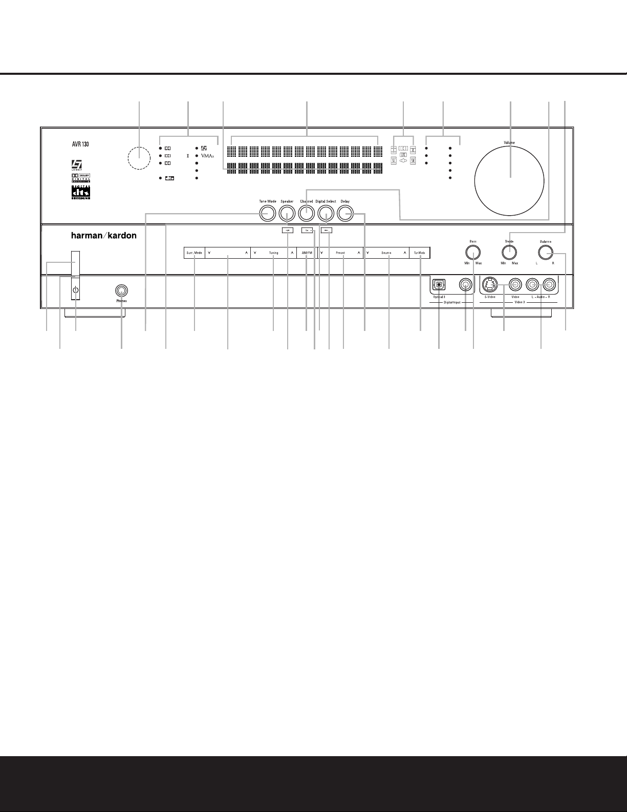
FRONT-PANEL CONTROLS
1 Main Power Switch
2 Power Indicator
3 Standby/On Switch
4 Headphone Jack
5 Tone Mode Selector Buttons
6 Speaker Selector
7 Surround Mode Group Selector
8 Surround Mode Selector
9 Tuning Selector
) ‹/› Buttons
! Tuner Band Selector
@ Set Button
# Digital Input Selector
$ Preset Stations Selector
% Delay Adjust Selector
^ Input Source Selector
& Tuner Mode Selector
* Optical 3 Digital Input
( Coaxial 3 Digital Input
Ó Bass Control
Ô Video 3 Video Input Jacks
Video 3 Audio Input Jacks
Ò Balance Control
Ú Treble Control
Û Channel Adjust Selector
Ù Volume Control
ı Input Indicators
ˆ Speaker/Channel Input Indicators
˜ Upper Display Line
¯ Lower Display Line
˘ Surround Mode Indicators
¸ Remote Sensor Window
DIGITAL LOGIC 7
VID 1
DVD
CD
FMAM
TAPE
VID 2
VID 3
PRO LOGIC
3 STEREO DSP
5 CH. STEREO
SURR. OFF
1
2
3
4
6
79
#
^
$
¸
˘
¯˜ ˆ Ú
Ò
Ô
(
*
Û
Ù
ı
5
8
)
!
@
)
&
%
6 CH
Surr. Select
Coaxial 3
Ó
NOTE: To make it easier to follow the instructions that refer to this illustration, a larger copy may be downloaded from the Product Support section for this product
at www.harmankardon.com.

6 FRONT-PANEL CONTROLS
FRONT-PANEL CONTROLS
8 Surround Mode Selector: Press this button
to select from among the available surround mode
options for the mode group selected.The specific
modes will vary based on the number of speakers
available,the mode group and if the input source is
digital or analog.For example, press the
Surround
Mode Group Selector
7 to select a mode grouping
such as Dolby or Logic 7, and then press this button
to see the available mode choices.For more information on mode selection, see pages 22 and 23.
9 Tuning Selector: Press the left side of the button
to tune lower-frequency stations and the right side of
the button to tune higher-frequency stations.When the
tuner is in the MANUAL mode,each tap will increase
or decrease the frequency by one increment.When
the tuner receives a strong enough signal for adequate
reception,
MANUAL TUNED will appear in the
Lower Display Line ¯. When the tuner is in the
AUTO mode,press the button once, and the tuner will
scan for a station with acceptable signal strength.
When the next station with a strong signal is tuned,
the scan will stop and the
Lower Display Line ¯
will indicate AUTO TUNED. When an FM Stereo
station is tuned, the display will read
AUTO ST
TUNED
.
To switch back and forth between the Auto and
Manual tuning modes,press the
Tuner Mode
Selector
&.
) ‹/› Buttons: When configuring the AVR 130’s
settings,use these buttons to select from the choices
available,
as shown in the Upper or Lower Display
Lines
˜¯.
! Tuner Band Selector: Press this button to turn
the AVR on and switch to select the Tuner as the input
source.Press it again to switch between the AM and
FM frequency bands.(See page 25 for more information on the tuner.)
@ Set Button: When making choices during the
setup and configuration process,press this button to
enter the desired setting into the AVR130’s memory.
# Digital Input Selector: Press this button to
select one of the digital inputs or the analog input for
any source.(See pages 23–25 for more information
on digital audio.)
$ Preset Stations Selector: Press this button to
scroll up or down through the list of stations that have
been entered into the preset memory.(See page 25
for more information on tuner presets.)
% Delay Adjust Selector: Press this button to
begin the steps required to enter delay settings.(See
page 19 for more information on delay times.)
^ Input Source Selector: Press this button to
change the input by scrolling up or down through the
list of
Input Indicators ı.
& Tuner Mode Selector:Press this button to select
Auto or Manual tuning.When the button is pressed so
that
AUTO appears in the Lower Display Line ¯,
the tuner will search for the next station with an
acceptable signal when the
Tuning Selector 9u
is pressed.When the button is pressed so that
MANUAL appears in the Lower Display Line ¯,
each press of the
Tuning Selector 9u will
increase the frequency.This button may also be used to
switch between Stereo and Mono modes for FM radio
reception.When weak reception is encountered, press
the button so that
MANUAL appears in the Lower
Display Line
¯ to switch to Mono reception. Press it
again to switch back to STEREO mode.(See page 25
for more information on using the tuner.)
* Optical 3 Digital Input: Connect the optical digital
audio output of an audio or video product to this jack.
When the input is not in use,be certain to keep the
plastic cap installed to avoid dust contamination that
might degrade future performance.
( Coaxial 3 Digital Input: This jack is used for
connection to the output of portable audio devices,
video game consoles or other products that have a
coax digital audio jack.
Ó Bass Control: Turn this control to modify the lowfrequency output of the left/right channels by as much as
±10dB,when the unit is in the “Surround Off” mode.
Ô Video 3 Video Input Jacks:These jacks may be
used for temporary connection to the composite or SVideo output of video games,camcorders or other
portable video products.You may make a connection
to either jack at any time,but not both simultaneously.
Video 3 Audio Input Jacks:These audio jacks
may be used for temporary connection to video
games or portable audio/video products such as camcorders and portable audio players.
Ò Balance Control: Turn this control to change the
relative volume for the front left/right channels.
NOTE: For proper operation of the surround modes
this control should be at the midpoint or “12 o’clock”
position.
Ú Treble Control:Turn this control to modify the high
frequency output of the left/right channels by as much as
±10dB,when the unit is in the “Surround Off” mode.
Û Channel Adjust Selector: Press this button to
begin the process of trimming the channel output levels using an external audio source.(For more information on output level trim adjustment, see page 26.)
Ù Volume Control: Turn this knob clockwise to
increase the volume,counterclockwise to decrease
the volume.If the AVR 130 is muted, adjusting the
Volume Control Ù will automatically release
the unit from the silenced condition.
ı Input Indicators: The name of the selected input
will appear here.
ˆ Speaker/Channel Input Indicators: These indi-
cators are multipurpose,indicating both the speaker
type selected for each channel and the incoming datasignal configuration.The left, center,right, right surround
and left surround speaker indicators are composed of
three boxes,while the subwoofer is a single box. The
center box lights when a “small”speaker is selected,
and the two outer boxes light when “large”speakers are
selected.When none of the boxes are lit for the center,
surround or subwoofer channels,no speaker has been
assigned that position. (See page 16 for more information on configuring speakers.) The letters inside each
box display the active input channels.For standard analog inputs,only the L and R will light, indicating a stereo
input. For a digital source, the indicators will light to display the channels being received at the digital input.
When the letters flash, the digital input has been interrupted. (See pages 18 –19 for more infor mation on the
Channel Indicators.)
˜ Upper Display Line: Depending on the unit’s sta-
tus,a variety of messages will appear here.In normal
operation, this line will show the current input source
and which analog or digital input is in use.When the
tuner is the input, this line will identify the station as AM
or FM and show the frequency and preset number, if
any.
¯ Lower Display Line: Depending on the unit’s sta-
tus,a variety of messages will appear here.In normal
operation, the current surround mode will show here.
˘ Surround Mode Indicators: The name of the
selected surround mode will appear here.
¸ Remote Sensor Window: The sensor behind
this window receives infrared signals from the remote
control.Aim the remote at this area and do not block
or cover it.
37
REAR-PANEL CONNECTIONS 7
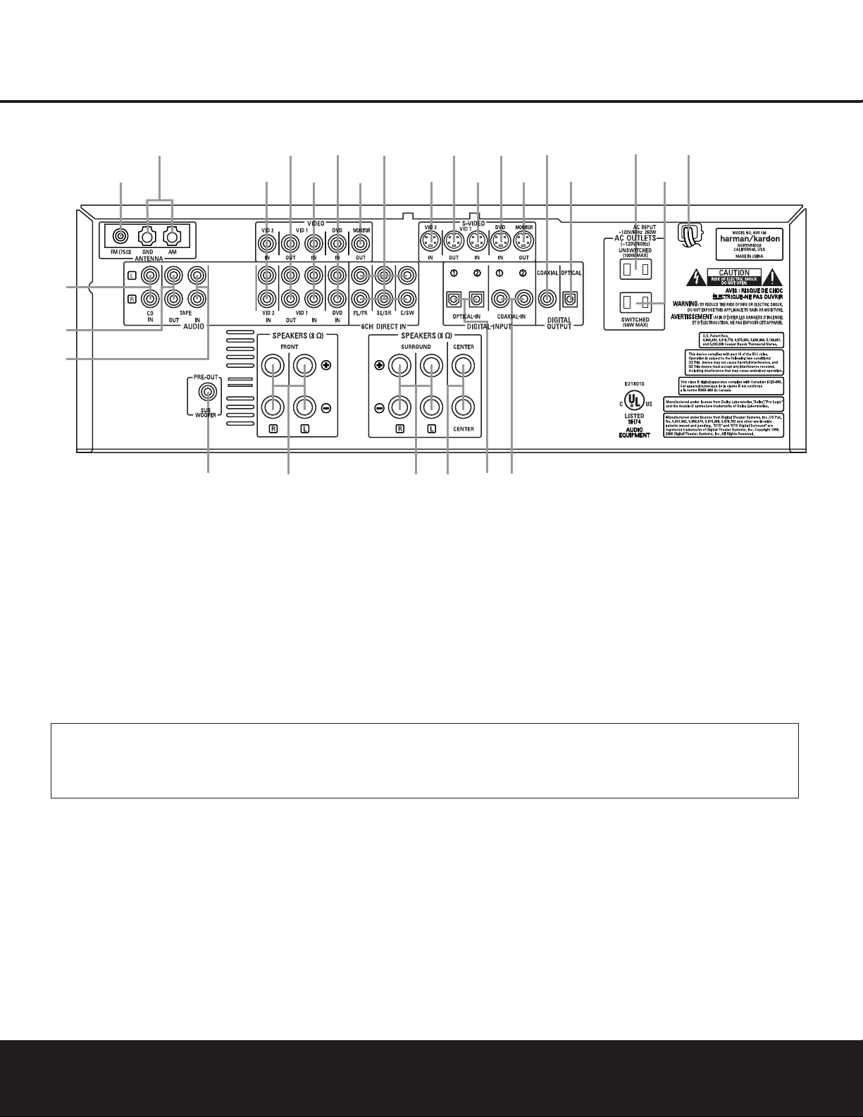
REAR-PANEL CONNECTIONS
•
¢
∞
§
¶
‚
⁄
¤
fi
°
b
c
d
e
g
h
ª
¡
™
£
f
a
·
‡
fl
›
‹
¡ CD Audio Inputs
™ Tape Outputs
£ Tape Inputs
¢ Subwoofer Output
∞ Front Speaker Outputs
§ Surround Speaker Outputs
¶ Center Speaker Outputs
• Optical Digital Inputs
ª Coaxial Digital Inputs
‚ AC Power Cord
⁄ Switched AC Accessory Outlet
¤ Unswitched AC Accessory Outlet
‹ Optical Digital Output
› Coaxial Digital Output
fi S-Video Monitor Output
fl DVD S-Video Input
‡ Video 1 S-Video Input
° Video 1 S-Video Output
· Video 2 S-Video Input
a 6-Channel Direct Inputs
b Video Monitor Output
c DVD Audio/Video Inputs
d Video 1 Audio/Video Inputs
e Video 1 Audio/Video Outputs
f Video 2 Audio/Video Inputs
g AM Antenna Terminals
h FM Antenna Jack
¡ CD Audio Inputs: Connect these jacks to the out-
put of a Compact Disc player or changer.
™ Tape Outputs: Connect these jacks to the
RECORD/INPUT jacks of an audio recorder.
£ Tape Inputs: Connect these jacks to the
PLAY/OUTjacks of an audio recorder.
¢ Subwoofer Output: Connect this jack to the line-
level input of a powered subwoofer. If an external subwoofer amplifier is used, connect this jack to the subwoofer amplifier input.
∞ Front Speaker Outputs: Connect these outputs
to the matching + and – terminals on your front
speakers.
§ Surround Speaker Outputs: Connect these out-
puts to the matching + or – terminals on your left and
right surround speakers.
¶ Center Speaker Outputs: Connect these speak-
er outputs to the matching (+) and (–) terminals on
your center channel speaker.
NOTE ON ALL SPEAKER CONNECTIONS:When
making speaker connections always make certain to
maintain correct polarity by connecting the black terminal to the negative (–) terminal on the speakers.
Connect the blue terminal to the positive (+) terminal
on the left surround speaker and the gray terminal to
the positive (+) terminal on the right surround speaker.
When a newer complete 5-piece speaker system is
used, the individual speakers may have matching color
terminals in accordance with CEA specifications,while
existing speakers typically use a red terminal for the
positive (+) speaker wire connection. (See page 13
for more information on speaker polarity.)
NOTE: To make it easier to follow the instructions that refer to this illustration, a larger copy may be downloaded from the Product Support section for this product at
www.harmankardon.com.
NOTE:To assist in making the correct connections for
multichannel input, output and speaker connections,
all connection jacks and terminals are color-coded
in conformance with the CEA standards as follows:
Front Left: White
Front Right: Red
Center: Green
Surround Left: Blue
Surround Right: Gray
Subwoofer: Purple
Coaxial Digital Audio: Orange
Composite Video: Yellow

8 REAR-PANEL CONNECTIONS
• Optical Digital Inputs: Connect the optical digital
audio output from a DVD player, HDTV receiver,LD
player, satellite receiver,cable box, MiniDisc player or
recorder, or CD player to these jacks.The signal may
be either a Dolby Digital signal, a DTS signal or a
standard PCM digital source.
ª Coaxial Digital Inputs: Connect the coax digital
audio output from a DVD player, HDTV receiver,LD
player, satellite receiver,cable box, MiniDisc recorder or
CD player to these jacks.The signal may be either a
Dolby Digital signal, DTS signal or a standard PCM digital
source.Do not connect the RF digital output of an
LD player to these jacks.
NOTE: The default setting for the audio input associated
with DVD is the Coaxial Digital Input 1 ª. If you
connect the audio outputs of a DVD player to another
digital or analog audio jack, change the input setting
as shown on page 19.
‚ AC Power Cord: Connect the AC plug to an
unswitched AC wall outlet.
⁄ Switched AC Accessory Outlet:This outlet may
be used to power any device you wish to have turned
on or off at the same time as the AVR 130.Any device
connected to this outlet will be off when the AVR130
is in the Standby mode,and power will be supplied to
the outlet when the AVR130 is turned on.
¤ Unswitched AC Accessory Outlet: This outlet
may be used to power any AC device. The power will
remain on at this outlet regardless of whether the
AVR 130 is on or off.
IMPORTANT NOTE:The total power consumption of
all devices connected to the accessory outlets should
not exceed 100 watts.Do not connect power amplifiers
or other high-current-draw devices to these outlets.
‹ Optical Digital Output: Connect this jack to the
matching digital audio input connector on a digital
recorder such as a CD-R or MiniDisc recorder.
› Coaxial Digital Output: Connect this jack to the
matching digital audio input connector on a digital
recorder such as a CD-R or MiniDisc recorder.
fi S-Video Monitor Output: When your television
or other video display is equipped with an S-Video
input and you are using at least one video source
with S-Video capability,connect this jack to the SVideo input on the video display.
fl DVD S-Video Input: If you are not making a
direct connection from the component video outputs
of your DVD player to a television or other video display,connect the S-Video output of the DVD player to
this jack and then make certain that the
S-Video
Monitor Output
fi is also connected as described
above.
‡ Video 1 S-Video Input: If the product connected
to the
Video 1 Audio Inputs d has S-Video capability,connect this jack to the PLAY/OUT S-Video jack
on that unit and then make cerain that the
S-Video
Monitor Output
fi is also connected as described
above.
° Video 1 S-Video Output: If the product
connected to the
Video 1 Audio Outputs e has
S-Video capability,connect this jack to the REC/IN
S-Video jack on that unit.
· Video 2 S-Video Input: If the product connected
to the
Video 2 Audio Inputs f has S-Video capability,connect this jack to the PLAY/OUT S-Video jack
on that unit and then make certain that the
S-Video
Monitor Output
fi is also connected as described
above.
a 6-Channel Direct Inputs: Connect the outputs of
a DVD Audio or SACD player,or another product with
built-in multichannel decoding,to these jacks.
These jacks have been color-coded as follows to
assist you in making correct channel connections:
Front Left White
Front Right Red
Center Green
Surround Left Blue
Surround Right Gray
Subwoofer Purple
b Video Monitor Output: Connect this jack to the
composite video input of a TV monitor or video
projector to view the output of any standard video
source selected by the receiver’s video switcher.
c DVD Audio/Video Inputs: Connect one of these
jacks to the composite video and L/R analog audio
output jacks on a DVD or other video source.
NOTE: The default setting for the audio input associated
with DVD is the Coaxial Digital Input 1 ª. If you
connect the audio outputs of a DVD player to another
digital or analog audio jack, change the input setting
as shown on page 19.
d Video 1 Audio/Video Inputs: Connect these
jacks to the
PLAY/OUTcomposite video jacks and
L/R audio jacks on a VCR or other video source.
e Video 1 Audio/Video Outputs: Connect these
jacks to the
RECORD/INPUT composite video and
L/R audio jacks on a VCR.
f Video 2 Audio/Video Inputs:Connect these
jacks to the
PLAY/OUTcomposite video and L/R
audio jacks on a TV,VCR or other video source.
g AM Antenna Terminals:Connect the AM loop
antenna supplied with the receiver to these terminals.If
an external AM antenna is used,make connections to
the
AM and GND terminalsin accordance with the
instructions supplied with the antenna.
h FM Antenna Jack: Connect the supplied indoor or
an optional external FM antenna to this jack.
Note on Video Connections:When connecting a
source device such as a VCR,DVD Player,cable or
satellite set top box or video game to the AVR,use
either a composite or S-Video connection for each
input, but not both.
REAR-PANEL CONNECTIONS
REMOTE CONTROL FUNCTIONS 9
REMOTE CONTROL FUNCTIONSREMOTE CONTROL FUNCTIONS
●
●
●
●
●
●
●
●
●
●
●
●
●
s
a
bc
d
e
f
g
h
j
n
n
pp
o
q
r
t
v
`
32
30
29
28
36
37
38
39
40
31
z
x
35
POWER
MUTE
AVR
DVD
AM/FM
CD
TAPE
VID 2
VCR
TV
CBL/SAT
6 CH.
VID 1
VID 3
OFF
ON
SLEEP
T/V
SURR.
CH.
VOL.
G
U
I
D
E
C
H
.
E
X
I
T
D
I
G
I
T
A
L
M
E
N
U
S
P
K
R
P
R
E
V
.
C
H
.
D
E
L
A
Y
SET
1
2
3
4
7
6
5
9
0
TUN-M
MEM
M2
M3
M4
D.SKIP
M1
DIRECT
TUNING
DOLBY
DTS SURR
DTS NEO:6
STEREO
LOGIC 7
SKIP
UP
DOWN
PRESET
CLEAR
TEST
NIGHT
130
8
l
u
DIM
i
k
m
34
33
w
y
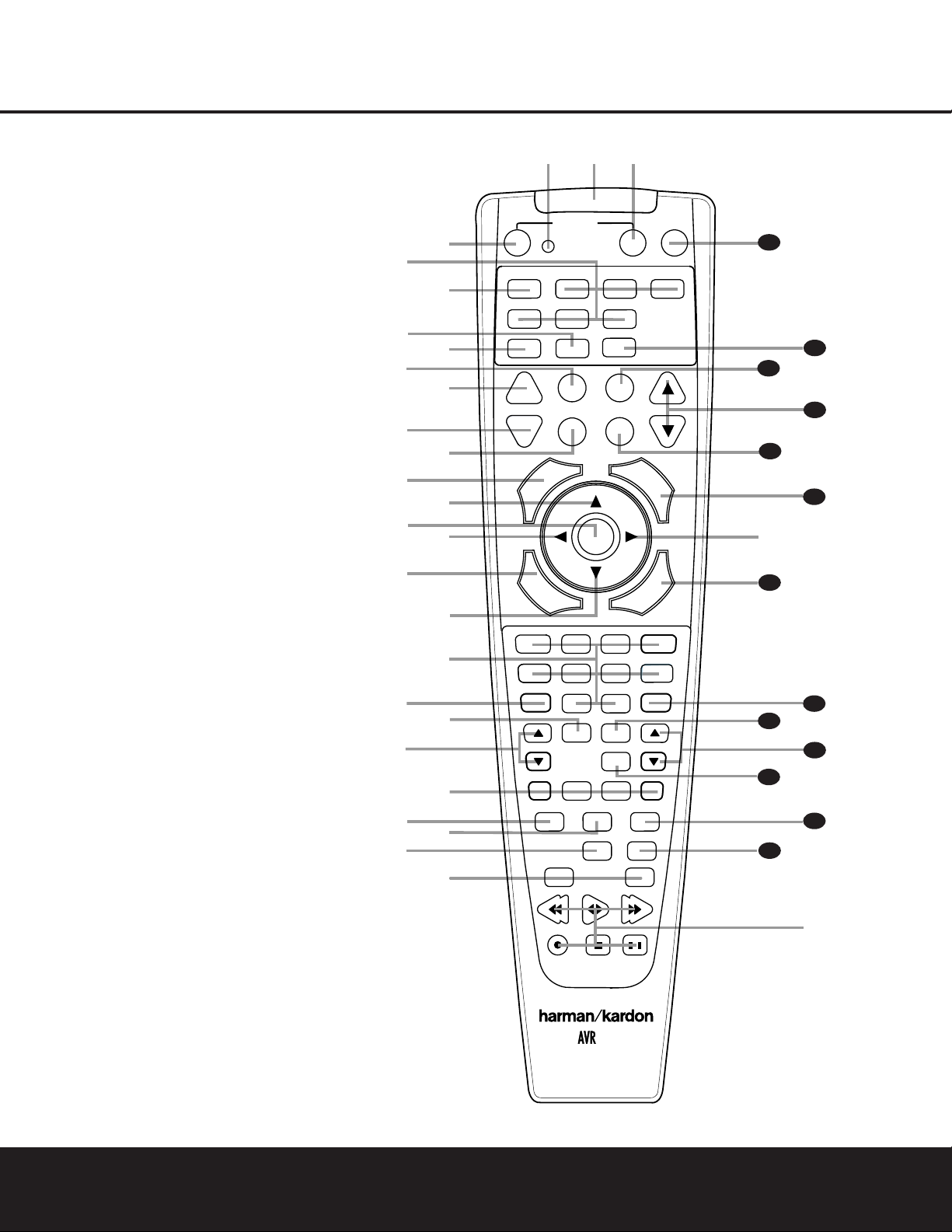
a Power Off Button
b IR Transmitter Window
c Program Indicator
d Power On Button
e Input Selectors
f AVR Selector
g AM/FM Tuner Select
h Dim Button
i Test Button
j Sleep Button
k DSP Surround Mode Selector
l Night Mode Button
m Channel Select Button
n
⁄¤
Buttons
o Set Button
p
‹›
Buttons
q Digital Select Button
r Numeric Keys
s Tuner Mode Button
t Direct Button
u Tuning Up/Down Buttons
v Macro Buttons
w Dolby Mode Select Button
x DTS Digital Mode Select Button
y Logic 7 Mode Select Button
z Track Skip Up/Down Buttons
` Transport Controls
28
Stereo Mode Selector Button
29
DTS Neo:6 Mode Select Button
30
Disc Skip Button
31
Preset Up/Down Buttons
32
Clear Button
33
Memory Button
34
Delay Button
35
Speaker Select Button
36
Spare Button
37
Volume Up/Down Button
38
TV/Video Button
39
6-Channel Direct Input Button
40
Mute
NOTES:
• The function names shown here refer to each
button’s feature when used with the AVR 130.
Most buttons have additional functions when
used with other devices.See pages 31–32 for
a list of these functions.
• To make it easier to follow the instructions that
refer to this illustration, a larger copy may be
downloaded from the Product Support section for
this product at www.harmankardon.com.

10 REMOTE CONTROL FUNCTIONS
REMOTE CONTROL FUNCTIONS
IMPORTANT NOTE:The AVR 130’s remote may be
programmed to control up to seven devices,including
the AVR 130.Before using the remote,remember to
press the
Input Selector Button e that corresponds to the unit you wish to operate.In addition, the
AVR 130’s remote is shipped from the factory to operate the AVR 130 and most recent Harman Kardon
products.The remote is also capable of operating a
wide variety of other products using the control codes
that are part of the remote.Before using the remote
with other products,follow the instructions on pages
27–29 to program the proper codes for the products
in your system.
It is also important to remember that many of the buttons on the remote take on different functions,depending on the product selected using the Device Control
Selectors.The descriptions shown here primarily detail
the functions of the remote when it is used to operate
the AVR 130.(See pages 31–32 for information about
alternate functions for the remote’s buttons.)
a Power Off Button: Pressing this button turns off
(places in the Standby mode) the device that was last
selected by pressing one of the
Input Selectors e.
To place the AVR 130 in the Standby mode,first press
the
AVR Selector Button f and then press this
button.
b IR Transmitter Window:Point this window
towards the AVR 130 when pressing buttons on the
remote to make certain that infrared commands are
properly received.
c Program Indicator: This three-color indicator is
used to guide you through the process of programming the remote.(See pages 27–29 for information
on programming the remote.)
d Power On Button: After selecting a device by
pressing one of the
Input Selectors e, press this
button to turn the device on.To turn on the AVR 130,
press the
AVR Selector Button f.
e Input Selectors: Pressing one of these buttons
will perform three actions at the same time.First, if the
AVR 130 is not turned on, this will power up the unit.
Next, it will select the source shown on the button as
the input to the AVR130. Finally,it will change the
remote control so that it controls the device selected.
After pressing one of these buttons you must press
the
AVR Selector Button f again to operate the
AVR 130’s functions with the remote.
f AVR Selector: Pressing this button will switch the
remote so that it will operate the AVR130’s functions.If
the AVR130 is in the Standby mode,it will also tur n the
AVR 130 on.
g AM/FM T uner Select: Press this button to select
the AVR130’s tuner as the listening choice.Pressing
this button when the tuner is already in use will switch
between the AM and FM bands.
h Dim Button: Press this button to activate the
Dimmer function, which reduces the brightness of the
front-panel display,or turns it off entirely.The first
press of the button shows the default state,which is
full brightness,by indicating
DIMMER FULL in
the
Lower Display Line ¯. Press the button again
within five seconds to reduce the brightness by 50%,
as indicated by
DIMMER HALF showing in the
Lower Display Line ¯. Press the button again
within five seconds and the main display will go completely dark. Note that this setting is temporary,in that,
regardless of any changes,the display will always
return to full brightness when the AVR is turned on.In
addition, the
Power Indicator 2 will always remain
at full brightness regardless of the setting.This is to
remind you that the AVR is still turned on.
i Test Button: Press this button to begin the
sequence used to calibrate the AVR 130’s output levels.
(See pages 18–19 for more information on calibrating
the AVR 130.)
j Sleep Button: Press this button to place the unit
in the Sleep mode.After the time shown in the display,
the AVR 130 will automatically go into the Standby
mode.Each press of the button changes the time until
turn-off in the following order:
Note that when the Sleep function is in use,the display will dim to half brightness.This button is also
used to change channels on your TV when the TV is
selected, and it is also used to end the process of
creating a macro command. (See page 28 for more
information on creating macros.)
k DSP Surround Mode Selector: Press this but-
ton to select one of the DSP surround modes,such as
VMAx, Hall or Theater. Each press of the button
selects another mode.(See page 22 for more information on surround modes.)
NOTE: The Sleep Button j and DSP Surround
Mode Selector
k may also function as the
Channel + and – keys when the remote is programmed for use with TVs, cable boxes,VCRs, satellite
receivers or other video devices with tuners.See page
29 for information on programming the remote for
Channel Control Punch-Through capability so that you
may change channels on a separate device when the
remote is in AVR mode.
l Night Mode Button: Press this button to acti-
vate the Night mode.This mode is available in specially
encoded digital sources to preserve dialogue (center
channel) intelligibility at low volume levels.
m Channel Select Button: This button is used to
start the process of setting the AVR 130’s output levels to
an external source.Once this button is pressed, use the
⁄/¤
Buttons n to select the channel being adjust-
ed, then press the
Set Button o, followed by the
⁄/¤
Buttons n again, to change the level setting.
(See page 26 for more information.)
n
⁄¤
Buttons:These multipurpose buttons are
used to change configuration settings,such as output
levels.When changing an item such as the surround
mode or digital input directly,first press the function or
mode to be changed (e.g., press the
Digital Select
Button
q to change the digital input) and then press
this button to scroll through the list of available choices.
o Set Button: This button is used to enter settings
into the AVR 130’s memory. It is also used in the
setup procedures for delay time,speaker configuration
and channel output level adjustment.
p ‹› Buttons: Thess buttons are not used to
operate or configure the AVR 130’s settings, but they
are used as part of the navigation system for other
devices you may operate with the remote,such as DVD
players,video displays and cable or satellite set top
boxes.(See pages 28 and 30–32 for more information
on using the AVR’s remote with other products.)
q Digital Select Button: Press this button to
assign one of the digital inputs
•ª*( to the
source currently in use.(See page 23 for more information on using digital inputs.)
r Numeric Keys: These buttons serve as a ten-
button numeric keypad to enter tuner preset positions.
They are also used to select channel numbers when
TV has been selected on the remote,or to select track
numbers on a CD,DVD or LD player,depending on
how the remote has been programmed.
90
min80min70min60min50min
40
min
30
min20min10min
OFF

REMOTE CONTROL FUNCTIONS 11
REMOTE CONTROL FUNCTIONS
s Tuner Mode Button: Press this button to change
the tuner mode between manual and automatic.When
the button is pressed so that
AUTO appears at the
left side of the
Lower Display Line ¯, only stations
with acceptable signal quality will be tuned, and the
tuner will play FM stations in stereo,when available. In
the
AUTO mode,when the Tuning Up/Down
Buttons
9u are pressed, the unit will automatically search for the next available station with good
signal strength.When this button is pressed so that
MANUAL appears on the left side of the Lower
Display Line
¯ each press of the Tuning
Up/Down Buttons
9u will move the frequency
up or down in single-step increments.When the FM
band is in use,pressing this button so that the
MANUAL mode is activated will enable you to tune
stations with weak signals by changing to monaural
reception. (See page 25 for more information.)
t Direct Button: When the tuner is in use,press
this button to start the sequence for direct entry of a
station’s frequency. After pressing the button simply
press the proper
Numeric Keys r to select a sta-
tion. (See page 25 for more information on the tuner.)
u Tuning Up/Down Buttons: When the tuner is in
use,these buttons will tune up or down through the
selected frequency band. If the
Tuner Mode Button
s& has been pressed so that the word AUTO
appears in the Lower Display Line ¯, pressing
either of the buttons will cause the tuner to seek the
next station with acceptable signal strength for quality
reception.When the word
MANUAL appears in the
Lower Display Line ¯, pressing these buttons will
tune stations in single-step increments.(See page 25
for more information.)
v Macro Buttons: Press these buttons to store or
recall a “Macro”, which is a preprogrammed sequence
of commands stored in the remote.(See page 28 for
more information on storing and recalling macros.)
w Dolby Mode Select Button: This button is used
to select from among the available Dolby Surround
processing modes.Each press of this button will select
one of the Dolby Pro Logic II modes or Dolby 3
Stereo.When a Dolby Digital-encoded source is in use,
the Dolby Digital mode may also be selected. (See
page 22 for the available Dolby surround mode
options.)
x DTS Digital Mode Select Button: Although
the AVR 130 will automatically select DTS processing
when the digital audio input source is a DTS data
stream, you may also press this button to select
DTS playback.
y Logic 7 Mode Select Button: Press this button
to seelct from among the available Logic 7 surround
modes.(See page 22 for available Logic 7 options.)
z Track Skip Up/Down Buttons: These buttons
have no direct function with the AVR130, but when
used with a compatibly programmed CD or DVD
changer, they will change the track or chapter of the
disc currently being played in the changer.
` Transport Controls: These buttons do not have
any functions for the AVR130, but they may be programmed for the forward/ reverse play operation of a
wide variety of CD or DVD players,and audio or video
cassette recorders.(See page 29 for more information
on programming the Transport Control Punch-Through
capability of the remote.)
Stereo Mode Select Button: Press this button
to select a stereo playback mode.When the button is
pressed so that
DSP SURR OFF appears in the
Lower Display Line ¯, the AVR will operate in a
bypass mode with true fully analog,two-channel
left/right stereo mode with no surround processing or
bass management as opposed to other modes where
digital processing is used.When the button is pressed
so that
SURROUND OFF appears in the Lower
Display Line
¯, you may enjoy a two-channel presentation of the sound along with the benefits of bass
management.When the button is pressed so that
5
CH STEREO
appears,the stereo signal is routed
to all five speakers,if installed. (See page 22 for more
information on stereo playback modes.)
DTS Neo:6 Mode Select Button: Press this
button to select a DTS Neo:6 mode.These modes
take a two-channel stereo- or matrix surroundencoded source and create a full five-channel sound
field. (See page 22 for the available DTS Neo:6
options.)
Disc Skip Button:This button has no direct
function for the AVR 130,but when used with a compatibly programmed CD or DVD changer, it will change
the disc currently being played in the changer. (See
page 28 for more information on using the remote
with other devices.)
Preset Up/Down Buttons: When the tuner is in
use,press these buttons to scroll through the stations
programmed into the AVR 130’s memory.When some
source devices,such as CD players,VCRs and cassette decks,are selected using the device
Input
Selectors
e, these buttons may function as
Chapter Step or Track Advance.
Clear Button: Press this button to clear incorrect
entries when using the remote to directly enter a radio
station’s frequency.
Memory Button: Press this button to enter a radio
station into the AVR 130’s preset memory. First,tune the
desired station, and then press this button.When two
underline indicators flash at the right side of the
Upper
Display Line
˜, press the numeric keys for the preset number between 01 and 30 that you wish to
assign to the station within five seconds.(See page 25
for more information.)
Delay Button: Press this button to begin
the process for setting the delay times used by the
AVR 130 when processing surround sound.After
pressing this button, the delay times are entered by
pressing the
Set Button o and then using the
⁄/¤
Buttons n to change the setting. Press
the
Set Button o again to complete the process.
(See page 19 for more information.)
Speaker Select Button: Press this button to
begin the process of configuring the AVR 130’s bass
management system for use with the type of speakers used in your system. Once the button has been
pressed, use the
⁄/¤
Buttons n to select the
channel you wish to set up.Press the
Set Button
o and then select another channel to configure.
When all adjustments have been completed, press
the
Set Button o twice to exit the settings and
return to normal operation. (See page 16 for more
information.)
Spare Button:This button does not have any
function for the operation of the AVR130, but it is
available for use when programmed with the code
from another remote.(See page 27 for information
on programming the remote with codes for other
devices.)
Volume Up/Down: Press these buttons to raise
or lower the system volume.(See page 29 for more
information on programming the Volume PunchThrough capability of the remote,which allows you to
change the AVR130’s volume while the remote is set
to control another device.)
TV/Video Selector: This button does not have a
direct function on the AVR130, but when used with a
compatibly programmed VCR,DVD or satellite receiver
that has a “TV/Video”function, pressing this button will
switch between the output of the player or receiver
and the external video input to that player. Consult the
owner’s manual for your specific player or receiver for
the details of how it implements this function.
28
29
30
31
32
33
34
35
36
37
38

12 REMOTE CONTROL FUNCTIONS
REMOTE CONTROL FUNCTIONS
6-Channel Direct Input: Press this button to
select the component connected to the
6-Channel
Direct Input
a as the audio source.Note that when
you wish to use the 6-Channel Direct Input in conjunction with a video source,you must first select the video
source by pressing one of the
Input Selectors e.
Then press this button to choose the
6-Channel
Direct Input
a as the audio source.
Mute: Press this button to momentarily silence
the AVR 130 or TV set being controlled, depending on
which device has been selected.When the AVR 130
is muted, press this button or use the
Volume
Control
Ù to return to the previous volume
level.When the AVR 130 remote is being programmed
to operate another device or when a macro command
is being programmed, this button is pressed with the
Input Selector Button e to begin the programming process.(See page 27 for more information on
programming the remote.)
39
40
37

INSTALLATION AND CONNECTIONS 13
INSTALLATION AND CONNECTIONS
System Installation
After unpacking the unit, and placing it on a solid surface
capable of supporting its weight, you will need to make
the connections to your audio and video equipment.
Audio Equipment Connections
We recommend that you use high-quality interconnect
cables when making connections to source equipment
and recorders to preserve the integrity of the signals.
When making connections to audio source equipment
or speakers it is always a good practice to unplug the
unit from the AC wall outlet.This prevents any possibility of accidentally sending audio or transient signals to
the speakers that may damage them.
1. Connect the analog output of a CD player to the
CD Audio Inputs ¡.
NOTE: When the CD player has both fixed and vari-
able audio outputs it is best to use the fixed output
unless you find that the input to the receiver is so low
that the sound is noisy,or so high that the signal is
distorted.
2. Connect the analog Play/Out jacks of a cassette
deck, MD,CD-R or other audio recorder to the
Tape
Input Jacks
£. Connect the analog Record/In jacks
on the recorder to the
Tape Output Jacks ™ on the
AVR 130.
3. Connect the output of any digital sources to the
appropriate input connections on the AVR 130 rear
panel. Note that the
Optical and Coaxial Digital
Inputs
•ª*( may be used with a Dolby
Digital or DTS source,such as a DVD player,or the
output of a conventional CD or LD player’s PCM
(S/P-DIF) output.
4.Connect the
Optical Digital Output ‹ or Coaxial
Digital Output
› on the rear panel of the AVR130 to
the matching digital input connections on a CD-R or
MiniDisc recorder.
5.Assemble the AM Loop Antenna supplied with the
unit so that the tabs at the bottom of the antenna loop
snap into the holes in the base.Connect it to the
AM
and GND Screw Terminals g .
6. Connect the supplied FM antenna to the
FM
Antenna (75 ohm) Connection
h.The FM antenna
may also be an external roof antenna, an inside powered or wire lead antenna or a connection from a
cable TV system.Note that if the antenna or connection uses 300-ohm twin-lead cable,you must use the
300-ohm-to-75-ohm adapter supplied with the unit to
make the connection.
7. Connect the front, center and surround
Speaker
Outputs
∞§¶ to the respective speakers.
To ensure that all the audio signals are carried to your
speakers without loss of clarity or resolution, we suggest that you use high-quality speaker cable.Many
brands of cable are available and the choice of cable
may be influenced by the distance between your
speakers and the receiver, the type of speakers you
use,personal preferences and other factors.Your
dealer or installer is a valuable resource to consult in
selecting the proper cable.
Regardless of the brand of cable selected, we recommend that you use a cable constructed of fine,multistrand copper with a gauge of 14 or smaller. Remember
that in specifying cable,the lower the number,the
thicker the cable.
Cable with a gauge of 16 may be used for short runs
of less than ten feet.We do not recommend that you
use cables with an AWG equivalent of 18 or higher due
to the power loss and degradation in performance that
will occur.
Cables that are run inside walls should have the appropriate markings to indicate listing with UL, CSA or other
appropriate testing agency standards.Questions about
running cables inside walls should be referred to your
installer or a licensed electrical contractor who is familiar with the NEC and/or the applicable local building
codes in your area.
When connecting wires to the speakers,be certain to
observe proper polarity.Remember to connect the
“negative” or “black”wire to the same ter minal on
both the receiver and the speaker. The AVR 130
conforms to the CEA-recommended color-coding for
speaker terminals.Accordingly,the positive (+) terminal, which was previously red, is now a specific color
to assist you in making the correct connections.If your
speakers have color-coded connections, match the
terminal on the AVR130 to the like terminal on your
speakers.For existing speakers with a red terminal
for the positive connection, the connections on the
AVR 130 are as follows:
Front Left = White Front Right = Red
Center = Green
Surround Left = Blue Surround Right = Gray
While most speaker manufacturers adhere to an
industry convention of using black terminals for negative and red ones for positive,some manufacturers
may vary from this configuration.To ensure proper
phase and optimal performance,consult the identification plate on your speaker or the speaker’s manual to
verify polarity.If you do not know the polarity of your
speaker, ask your dealer for advice before proceeding,
or consult the speaker’s manufacturer.
We also recommend that the length of cable used
to connect speaker pairs be identical. For example,
use the same length piece of cable to connect the
front-left and front-right or surround-left and surround-right speakers,even if the speakers are a
different distance from the AVR 130.
8. Connections to a subwoofer are normally made via
a line-level audio connection from the
Subwoofer
Output
¢ to the line-level input of a subwoofer with
a built-in amplifier. When a passive subwoofer is used,
the connection first goes to a power amplifier, which
will be connected to one or more subwoofer speakers.
If you are using a powered subwoofer that does not
have line-level input connections,follow the instructions furnished with the speaker for connection
information.
Video Equipment Connections
Video equipment is connected in the same manner as
audio components.Again, the use of high-quality interconnect cables is recommended to preserve signal quality.
Although any compatible video device may be connected to any video input or output, to make programming device codes into the remote control easier, we
recommend that you connect your VCR or DVD
recorder or a personal video recorder (PVR) to the
Video 1 Audio/Video and S-Video Inputs ‡d,
your television to the
Video 2 Audio/Video Input
·f, and your cable-TV converter or satellite
receiver to the
Video 3 Connectors Ô.
1. Connect a VCR’s audio and video Play/Out jacks to
the
Video 1 Audio/Video and S-Video Input Jacks
‡d on the rear panel. The Audio and Video
Record/In jacks on the VCR should be connected to
the
Video 1 Audio/Video and S-Video Output
Jacks
°e on the AVR130.
2. Connect the analog audio and video outputs of a
television set or any other video source to the
Video 2
Audio/Video and S-Video Jacks
·f.
3. Connect the analog audio and video outputs of a
cable TV converter or satellite receiver, or any other
video source,to the
Video 3 Jacks Ô on the
front panel of the AVR 130.

14 INSTALLATION AND CONNECTIONS
4. Connect the left/right analog audio outputs of a
DVD or laser disc player to the
DVD Audio Inputs
c. Connect the composite video output of your
DVD player to the
DVD Video Input c or the DVD
player’s S-Video output to the
DVD S-Video Input
fl.However, if your DVD player and video display
both support component video,you should make
that connection directly.
When a digital audio connection is used for your
DVD player, the default connection is the
Coaxial
Digital Input 1 Jack
ª. However,the connection
may also be made to any of the
Optical •* or
Coaxial ª( Digital Inputs, provided that the
digital input source selection is changed as shown on
page 23.
For DVD players with DVD-Audio or SACD playback
capability,connect the 6-channel line-level audio outputs to the
6-Channel Direct Inputs a. When you
wish to hear the DVD-Audio or SACD playback, first
select the DVD Input on the AVR in order to select the
video signal from the DVD player, then select the 6Channel Direct Input source for the audio.
5. Connect the digital audio outputs of a DVD player,
satellite receiver, cable box or HDTV converter to the
appropriate
Optical or Coaxial Digital Inputs
•ª*(.
6. Connect the
Video Monitor Output fib jacks
on the receiver to the composite or S-Video input of
your television monitor or video projector.
VIDEO CONNECTION NOTE:
• Composite and S-Video signals may only be viewed
in their native formats.The AVR 130 will not convert
signals from composite to S-Video,or vice versa.
S-Video inputs may only be viewed when the
AVR 130 is connected to a TV set or video display
with S-Video capability.If you use both standard
composite video and S-Video sources in your
system, it is important that you connect both an
S-Video cable and a standard composite video
cable (a coax cable with an RCA plug on both
ends) between the AVR130 and your TV or projector. When it is necessary to make both types of
connections to your TV set,use different inputs if
possible.Consult the instructions for your TV set or
projector for more information on connecting both
types of signals.
Power Connections
This unit is equipped with two accessory AC outlets.
They may be used to power accessory devices,but
they should not be used with high-current draw equipment such as power amplifiers.The total power draw
to each outlet may not exceed 100 watts.
The
Switched AC Accessory Outlet ⁄ will receive
power only when the unit is on.This is recommended
for devices that have no power switch or a mechanical
power switch that may be left in the “ON”position.
NOTE: Many audio and video products go into a
Standby mode when they are used with switched outlets,and cannot be fully turned on using the outlet
alone without a remote control command.
The
Unswitched AC Accessory Outlet ¤ will
receive power as long as the unit is plugged into a
powered AC outlet.
Finally,when all connections are complete,plug the
Power Cord ‚ into a non-switched 120-volt AC wall
outlet.You’re almost ready to enjoy the AVR 130!
INSTALLATION AND CONNECTIONS
 Loading…
Руководства Harman Kardon AVR130 Размер файлов: 3676 KB, Язык: English, Формат: pdf, Платформа: Windows/Linux, Дата: 2015-11-17
На данной странице вы можете скачать руководства Harman Kardon AVR130. Мы предлагаем вам ознакомиться с руководством пользователя, инструкцией по сервисному обслуживанию и ремонту.
Также здесь вы найдете список заказных номеров на комплектующие Harman Kardon AVR130.
Все файлы предоставляются исключительно в ознакомительных целях. И не являютя руководством по ремонту, а направлены лишь на то чтобы помочь вам более детально ознакомиться с принципом построения устройства.
Содержимое представленных здесь руководств требуют от вас знания технического английского языка.
Если вы собираетесь скачать руководство по сервисному обслуживанию Harman Kardon AVR130, иными словами сервис мануал, вы дожны обладать хотя бы минимальными познаниями в области электроники и пониманием базовых принципов работы электромеханических устройств.
Для просмотра руководств вам понадобится Adobe Acrobat Reader версии 9 и выше либо другая программа для просмотра pdf файлов.
В связи с популярностью информации представленной на сайте и ее бесплатного предоставления конечному пользователю, убедительная просьба использовать специальные программные продукты для многопотокового скачивания файлов.
Руководства для Harman Kardon AVR130
- Руководство пользователя (User manual)
- Руководство по сервисному обслуживанию (Service manual)
- Руководство по ремонту (Repair manual)
- Перечень комплектующих (PartList)
•
¢
∞
§
¶
‚
⁄
¤
fi
°
b
c
d
e
g
h
ª
¡
™
£
f
a
·
‡
fl
›
‹
AVR 130 REAR-PANEL CONNECTIONS
NOTE: To assist in making the correct connections for
multichannel input, output and speaker connections, all
connection jacks and terminals are color-coded in
conformance with the latest CEA standards as follows:
Front Left: White
Front Right: Red
Center: Green
Surround Left: Blue
Surround Right: Gray
Subwoofer: Purple
Coaxial Digital Audio: Orange
Composite Video: Yellow
¡ CD Audio Inputs
™ Tape Outputs
£ Tape Inputs
¢ Subwoofer Output
∞ Front Speaker Outputs
§ Surround Speaker Outputs
¶ Center Speaker Outputs
• Optical Digital Inputs
ª Coaxial Digital Inputs
· Video 2 S-Video Input
a 6-Channel Direct Inputs
b Video Monitor Output
c DVD Audio/Video Inputs
d Video 1 Audio/Video Inputs
e Video 1 Audio/Video Outputs
f Video 2 Audio/Video Inputs
g AM Antenna Terminals
h FM Antenna Jack
‚ AC Power Cord
⁄ Switched AC Accessory Outlet
¤ Unswitched AC Accessory Outlet
‹ Optical Digital Output
› Coaxial Digital Output
fi S-Video Monitor Output
fl DVD S-Video Input
‡ Video 1 S-Video Input
° Video 1 S-Video Output
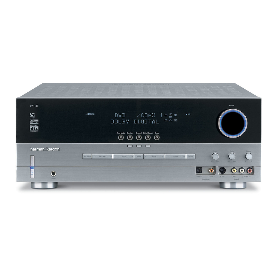
-
Contents
-
Table of Contents
-
Troubleshooting
-
Bookmarks
Quick Links
harman/kardon °
Power
for
the
Digital
Revolution_
AVR 130
AUDIO/VIDEO
RECEIVER
OWNER’S MANUAL
E
harmnn/kardon
i’
‘1
• r_
;_l_z • _
:==::==::= =::==::==:===:= =::== ::==::==::==::==:=== :===: = =::==::== ::==:
• _;
• _
©©©©©
,_, . ………..
,._ .,_,. _ A,. _ _,_, .6._ _
Related Manuals for Harman Kardon AVR 130
Summary of Contents for Harman Kardon AVR 130
-
Page 1
harman/kardon ° Power Digital Revolution_ AVR 130 AUDIO/VIDEO RECEIVER OWNER’S MANUAL • r_ ;_l_z • _ :==::==::= =::==::==:===:= =::== ::==::==::==::==:=== :===: = =::==::== ::==: • _; • _ ©©©©© harmnn/kardon ,_, …. ,._ .,_,. _ A,. _ _,_, .6._ _… -
Page 2
AVR 130 AUDIO/VIDEO RECEIVER I_ltrod/Jction Vrort Ptnd Co/trois i¢(aParil tXXlr1_(tio/s i_(rTlO t,o/tfo[ FHI(tioI I Isalia% / and Co me_ti(}/s S’,se /s alla%r Power t,OIIIIeCLiO/S Sp(aker.%(k ctk}r aid Plat( T rt Sys( S(tup Sp(akerS(tup Cotfiguri/g1heBLIHOL [d E)_! {St r((}}Mod{s E)©eratkx_ BasicOpemtbn SourceSelection Volume Coilt]oi Suuotmd MoB Chart… -
Page 3: Pour Le Canada
INTRODUCTION Thankyou for choosingHarmanKardonUWith Descriptionand Features • OnboardDolby*Digitaland DTS:'< Decoding AVR 1 suisa v(rsatlk aid ultit(siltedAiV t/( nufclas( ef a Hsrrnan Ksrdo_AVR]S0youart UsingCirrus’ ChipTechnology aboutto}egn aV y(trs o ii-.;enhg !py ent fle I c(Iv(r; i Icogxxating a wid( rangeef Ilsk /i ig •…
-
Page 4: Important Safety Information
SAFETY INFORMATION InstallationLocation Important Safety Information • I<eolie_lt el lel(}cat{ the receiviHg aHte_xla • R}eHSLi/e pr(}’pe[ o’aut% / andto avoidtie pote/ • il/(x(Tmse the sepmrmtioi/i}etw(Teli the eqdlDm(7_lt mlid VerifyLine VoltageBeforeUse thl for sak:ty mzards[}lacetie anitor afi; )nd uTc(71ver YaurAVRI:’1) hms )t(/d{sign(d form,cwitl 120 I(v(I sudac(Wlen piaci]gtlx anitel s sh(it b( •…
-
Page 5: Front Panel Controls
FRONT-PANEL CONTROLS [][] AVR130 OOOOO []Mtill( Se_ Button/ Digital i _putSeiectur ResetStations Selector DeiayAdjList Select4x Jet LI) J(.. (.((t)r Buttons Bi:ut Source Sdect4x []SpeakeriChannelinputil/dicat(xs ._t ],. Dilittl Ipui ,asxk;I 3 )iqittl/}u Ba;sCo/trol ][ln( [ i_snd . (l((. ( [ NOTE. ,..
-
Page 6
FRONT-PANEL CONTROLS SurroundMode Selector:Press/is butt)/ Input SourceSelector:P(ss thisx£er to ChannelAdjustSelector:Pisst]is nuto] to to’,d(ct fig arT/elK ! tx av_ihbkSllll(]lli!JrT/ed( c/a/(je th Ilput )y ‘,dolli_gui: er d(:u/t/eugl begi]tx [xocss of trirT/rT/ir g tx clarr ([ outx£ iv optionsfortl rT/od( g roupekct(d Fhe ) cific list(:{Input Indicators[] uqn( i a] ext rla[ tudio ‘,ouKx (F(x)r( inf0lrT/a… -
Page 7: Rear Panel Connections
REAR-PANEL CONNECTIONS € ///] r—A_S- IW man/ks sntmnmne C_JPUmZL_U_ ‘°+-+»1 I WARNING:I_ n_em_em_ w m_ELm_Cla » SPEAI_RS(8 _ — =®/o+ FRON T [+]== ° °+ lJ ® m Vid{u 2 SVide/put 4 ;» • I(. )1(._ ‘4/.h 0 _.LL ,, (_., ,_t I ,_ _._ DVD AudieiVid( e Inputs Fro_ S}etk(rOutputs _.
-
Page 8
REAR-PANEL CONNECTIONS Video2 Audio/VideoInputs: Con_(c1 th(s( t_ Optical DigitalInputs: Cox(ct t/o©tical digital thisjack end the/Tak( cer sil that th( S-Video Monitor Output _) is also cot i(ct d as dsclibd audk} o utputt,orna UVDpiay(/IiD]V uc(iver: D itcks to tl( PLAY/OUT c o posit(vd(o aid iR )bc)v pla/(r:sat(lilt uc(iver:cabl( }ox MiniUisc p la/(r or (cord({ or CD}hy(r tot_eseja<… -
Page 9: Remote Control Functions
REMOTE CONTROL FUNCTIONS _ ,. [ , ILI_..• _…(.t DSPgurrourdMod Slctor Chtnn(i S(k( _(Itt}/ S(t ButJol 4ili 41_ But£ons NIGHI Nu (/ic _(vs 7iulerMod( ButJ£}l li,fir g tJpi[}ow / BuU£}ns MacloBuUons Logi< _Sod( SkctBuon lrack Skipd > }o,,,/»» 8, o I!s’ _Steleo _vgod() Sele(tor S_tlito_/ DiscSkipButton…
-
Page 10: Control Functions
CONTROL FUNCTIONS REMOTE iMPORTANT N OTE: P I( AVR13Osr( (}i_rTlly AVRSelector:Pessing _isbutton wiilswill tl( NOTE:F_E SleepButton _ a_dDSPSuuound _uog[a edo cow(}lupt} svc/devices ildHdiig r(rT/O ( SO thatit will o p rat(t_(/VR 13(}shHctJuns I f Mode SelectorI_1 mayalsofu[ ctio/ astl( tic A//i<13B Beforeushgt_ElerT/oc c ember to tl( A//s<…
-
Page 11
CONTROL FUNCTIONS REMOTE TunerMode Button:PrEss t /S butIo/ to {:lane( Logic 7 Mode SelectButton:Piss this }Htlu ] ClearButton:Press tlis )Ht_u ] to el(atircorrect _utem_tic .t_hn bctwe n anal to sccict1,3 arT]o_g t _c _vaih)l I(xjl( 7 surreHnd (ntis w]e_ using t_e i(rnot__udi_(ctl/ml aradio tHli[ tic }uttenis pro ssc d sothatAU T O sppais atthe nods (See nagc22 foravailable [ugk:7 options) -
Page 12
CONTROL FUNCTIONS REMOTE 6-ChannelDirect Input: Pis’, thi’, )Litk//tL/ selectB co ]N( Itce/l(ct d t3 the 6-Channel Directinput_’_ astB a@ies@rce’!@ thtt w/(/ Di/ect h putin co!iunc /ULI WiS/t} @Cia II(i ti<Nwitl avido seuu: ysurnu'< firstselect t hevkJ(e souuse ) y p[(ss Ig(}/( of tileinput Selectors _h(n xessthisbL@N t} Clees( tile6-Channel _) Mute: Rss t/is buttN to HSH @t@v s ilence t/( AVR]30 el IV s(t }eilg centiolk d d( } /dingol… -
Page 13: Installation
INSTALLATION AND CONNECTIONS o tl System Installation 6 Collect t/{ supplied FMant(hi tte tile FM Whii( m(5st sb{ak(r ia/skctNrEP, ad/EIO Antenna(75 ohm) Connection_ 71( FMait( /la in@say COllV{i tJ(xl o f usilg blackt r ilafs fe nest i,f(I ulp,xkixj tl( uni IxJ pla(ixj it{31a elid urfax rT/_ 7 abe )t _/(x(rll_l Ion _llk /_a ,]11 illsid()},/ tiv{ aid redorles_(5r p esitN(s(5m(rnart£…
-
Page 14: Power Connections
INSTALLATION AND CONNECTIONS Power Connections 4 Cello( I( i(fYrigltanlog audb eutputse a DVD {x hsr discphyerto t_ DVDAudioInputs Fhi’, ( Ini i ccmipp(6 _ith t/e ac{ el/A eutlt Corld I( ce pesJtevideooLit}utofyour may}e usd to p}w(r scc(ssoryd vic(s but DVD nhy{r k} tl( DVDVideoInput _._ or th( DVD tl(y s]euidlot b( usedwitl ]igl cuue/t draw(qu!} player s S Videooutputto t/{ DVDS-VideoInput inert suc] as’pow( r ampiifiusFie toai i;ew(r draw…
-
Page 15
SYSTEH CONFIGURATION Agail tile’,., should }( IoctkxJsoflat tit bato of W/([I a]Jaudie vid(o t/d sy,£( T colin( (}tio[Ishay( t_( (abinetis at i(astwo f((t ]igl(r thantit li<,k}_ bel! Tad( /el( tf a f(wco/guratier a{!jtistrT/eilts (re (are 11( sp(akerss/eukJ } ere ee tlar six that ust )e ade A f(w rninut s sp(/t to ceue{tJy… -
Page 16
SYSTEH CONFIGURATION Rir/tlx AVRi :B {)/{iixr by }r< SSH 1tl( Fhci_ctxy default s ctti_g fortx speakcr c o/figura NOTE: I fy(}uc looseIogic 7 ts tl( SUHOUnd reed( tx AVRi 30 will _et rT/ak( t x lARGE SystemPowerControl[] o/th( front}sxi tienist}/ave small sp ak(/stt all ‘positio/s wit/t su)wu(}fr il«_alled you lay thist_p(ef sa}i optic}ravaiiabk fer c(/tr sp akc{ 1hisis du… -
Page 17: Configuring The Surround Off (Stereo) Modes
SYSTEH CONFIGURATION alibassirrer stier will/( std to tl fro/t tie His)@ tlat wil!be t_e(<l ir rnskirg s( tingsi_ parkaliarly w/(/t/( sp ak(rs tlsd areaH fl q(scy thiss(<tie_ I fiiig_t rn,_i_ sp(ak rs li site(l sak@t( t?( rned(is Iiew(v(r w/(n a sys t( ei,ent s}(akrs ar( largei@rangernod(ieyou •…
-
Page 18: Output Level Adjustment
SYSTEH CONFIGURATION Stereo-Direct(Bypass)Mode [egcir( erts ef yoursp(cificsp ak(rs usilgt/( stps R}adjust_d cali}ratetl( out[xt levis followtl(s Wl(n fir( t/tl(}g Stereogirectode is s(kct(d slewni/th( Sp(ak(rSeLl’;} s (<tk}ro/pag 16 st}s kor tccurak{aiibratio/it isa goodidet o )y i:r si_c] t he StereoMode SelectorI_ until make]es a(_jcb:rT/ rts will s(a(d il/aul kvofit( Output Level Adjustment SURROUND OFF appe_as i /…
-
Page 19: System Configuration
SYSTEM CONFIGURATION Co/tilLi tu adJlsttic ildividual s petk(rsunil Digitsl b yc _ecking/e ( sd}Hti/tic Lower Display 2 IrT/rT/editte]y pr(ssth( ,A/_ Buttons _ t/ey all hsv( t_e sam(voiH( No( tnt s{{ust Line [] r/is willer tbJe yeu(o configure allt/r(( ‘_1/1_ Buttons[] t} scroll t IrougItl( listef avti! (rts s_euld)e _de wiB tic I/V…
-
Page 20
SYSTEM CONFIGURATION : W/enthed(si/ed ed a)p(srsl_t_( LowerDisplav Line [] pr(sstl( Set Button 4 Ptuse five s(cer ds u/til th( unit times eut aid (tuns (o rerm)l op(ratJon [1is is eHr i _(£)tierl tlat tie (;o111ec%1 bd/e([1 K J/pHiSotlr(u slid ‘u[o(uss llg (}(J( 18S b(([ (it (d ilte tl( sys(… -
Page 21: Operation
OPERATION Volume Control WI(//uu wil!b( twty {r(:_rT] IOE forIll (x_end(d Basic Operation u(rbd of tJrTu it i alway a @)od ida t} co )let ly )I_e7@/avc[o i:k(d stup Ndco1figulakN • Ace;: I( volLI c to t co lura)l kwi usilg thc turnthe t,k off witl fi( fe)H pan MainPower of fi( AIR 130 it is si }lee ep(rateande@e/1he font panel V olume Control[]…
-
Page 22: Surround Mode Chart
OPERATION Surround Mode Chart MODE FEATURES /. siitbk oily wiB digitaii/p(t seurc(s{r cod(d withDoibyDigital d art It pr()vid( s t© to fly{ s( )attt( tudie c/all(is tld t sp((ial d<dicatdlow hqu<lcy Efl(ctsc/a/l(I £aihbk ally witl digiaii i:x]tsoul{(s elcod(d wiB DFSdata A.,ailabl( e n s}eciaiDVD[ D t/d tude oily dis<s [}IS previd(supto fly( s(parat(mail audk){ nil Isendasp {iai d(dkat(d lowfr(qu( i{y { isll(I DelbyPe I egicI [}eibyPre egic IIistile latestv{isienof Dol}y [aberatories}( /el ark s(irfou/dt(cl nelegyt/at d(cedesfull/ang(…
-
Page 23: Surround Mode Selection
OPERATION Surround Mode Selection d f9{ nodded s()mrd tracks)re )vaiiabl(on s(i(ct rheDelbyDi iLal n d D]Sed{s ay enl/,x s(kcted whe/a digital i nxlt is il co( h!additionwhe/s digi DVDaid D discsts w(ll ts o/special audk)only O_eef fir( moss irnpor a /t icattr(s of tx AVi< l }<} tels()cr c eis pres(nt tileAVR130will acts sti(nlly DfS discsYouay else anyI Dor CDnla}, is its a}ilityto r prod/£ea full ulticlairelsureuid…
-
Page 24: Night Mode
OPERATION Digital } its:r{a s will ( /ableDell b Digital d (cedi_g }etng’)l@edtie A//Rwill sut X T/SicslIy S.,Vitc / i01/e Agsi_ u ernb{rt_st so{ DVD dscs au lecord(d wit/}el S1 tnd 2 O vusionsof tl( sae sound Whet the urit s( /seePC!,,4 datafro CDser I Ds/au prop(rSUUOLmd ()de and_oelf proc(ss,lga},…
-
Page 25: Notes On Recording
OPERATION iMPORTANT N OTES ON DIGITAL PLAYBACK: Station Selection _uent(r a static/ Hiret/{ Temo[/fibs ur( tl{ eta ] W/{r le diqitai p hTb_ck seur(:e isst3′,){d (x i_ a 1 Ress_( AM/FMTunerSelectButton O tel usirg tl{ st(}s eutfineda}ov( F/u!: PauseFast F olwa/d el Chap(/S(ard rT/od(tl th KFT/Ot t u sdcd x! tlrle[ 8 8/ Hiput 1 Pussthe Memory Button _…
-
Page 26
OPERATION Output Level Trim Adjustment 6-Channel Direct Input Nounal e utputI(w[ td[uetrT/( /t f(}[th AVR1}0 is rle AVR130is {qLJipped k x (is( witl DVD Audb (qabli I(d (bins_{ (s: one a’, oulin((_ o/[sag{_, el SACF) Play(ree oil ‘pied(lets thtt iclud( t/i 18t/d 19 n some{as{s low(v({ it ay bedesi owno/bosld digit s ld( c(}d( i s fel for atethatthe abi( to adj(s t/( outp/Jt l (veieusJ/g}egra… -
Page 27: Programming The Remote
PROGRAMMING THE REMOTE ]Ire B//R130 is%i’)i:ed witl a }ew(#ulr (}tu rlt{r(d P(s t/( Input Selector_I a!ah aid 4 Pr s ]{ Input Selector_ aid r1(3( t ltt t]( co/tfoi fist willcentel )oil tl( r(cqvefs fa/ctb/s re flat th( rd ik’htv,.iil flasi i (‘ }fer (dliglt_r Jr I( rl_ .(.(.c(r…
-
Page 28: Macro Programming
PROGRAMMING THE REMOTE Macro Programming • Press t he SleepButton _ tuco }kt( t_( contioisconsult t ic I:t ictiol Listtablcson }agcs31 si!d :’,2[o Clebus( tel( <,ir<,tchccktic typcof process andstou trc macro scq/Jq(c Macros mabk/uu to easily rcpcatiuqu rtly uscd {£vicc bchcjco/troikd (cy rv VCR)Nextlooktt co }i]atio]sof co sidewithtic pressof a silgk tic rc oc co]tcui d isgrarT/ I}ictclrcd i ts before tl…
-
Page 29: Resetting The Remote Memory
PROGRAMMING THE REMOTE NOTE: A llpregrs mllgfor?/e u o( cod(sre(ded tl( devi:( ss(kcedbytl(/VR 130e[ the r(}rT/o ( R} 2 Resss the PlayButton_ rl( Program te eprat s}ecificd(vcesssucl asa R/DVD cabk po(/arnt/(r or(to Blarr(iBortroiRrcl F/ougl Indicator_ wl[ k)p fBffir ] aid stayar!bi )ox sstdlit [eceiv(r(x VCRsheukJ b ( compkt(d )doe i:ega r[ougi {e…
-
Page 30
PROGRAMMING THE REMOTE lh( diagrsTon thispsgeslows/( }uton I1{irT/)@fs harman/kardon (s(d i/(/( Fu/cior ist ta}ls or pagesi’,I 32 AYR 130 Do_o <o/fuset/s( ILJrT/be[s Wi/ _lOS{LJSd t/foug/OUi t l( f<St O ftlis a/Llai i o i_di<aie i_e s }eci{ks x ito/s us(dto op<lat the/s,/,/R 1 30s furciionslh( keyio tlose bution/urT/b(IsW/i(31… -
Page 31: Function List
FUNCTION LIST ButtonName AVR Function CDICD-R Tape VCR(VID1) TV(VIDI) SAT(VID3) CBL (VID3) PowerOn Pow{r(i)/ Pow{rC)] Po,id :)r Po,id On Po,ie[ 01i Pc)w({ O[ Pow(r : )ff PowerOff Pow{r()ff Pow{rC)ff Pow({Off Power O ff Po_({ bfl Power Off Po,ier Off Mut( Mute Mut( Mut(…
-
Page 32
FUNCTION LIST No. Button Name AVRFunction CD/CD-R VCR(VID1) TV(VID1) CBL(VID3) SAT(VID3) Direct [Ya:k_)i[c Clear Ckar Olaf Olaf Ckar Cl(ar Olaf Cl(ar 4B Preset Up SlewForward TuneDown [Br( Dowr P(vC/tpt(r lack i(rele/L D. Skip Preset Down _[cscLlUr(_)ou'[ Sl(:_w i <v ht[o S(:a[ )::riCle Ca/(:i Si _:… -
Page 33: Setup Code Table
SETUP CODE TABLE: Manufacturer/Brand Setup Code Number AIWA AMARK ADMIRAl AKAI AMPRO ANAM ] 12 B ALJ_tJNKr BROKSOHIC CAbD k CAP I AR Ck!_,TLRIO*’_ Ck!_,TR(}’IIC CITIZ_v C ASSIC COI’,IC E I_F(} COI’,JT kC CORANDO CORO_,,ADO CRAIG CROW_,, CLJRF!S MKF£S DAkWO(} DAYIRO_’_ DGI I INK DY»,IASI Y…
-
Page 34
SETUP CODE TABLE: Manufacturer/Brand Setup Cede Number I (}C, IK I UXMAI’,J I Xl MAO_,A’.’OX MARA;,,TZ M£ SLJl MEMOREX ME]Z M NER¢/ M’ SUBSIII f,,£1@,,A[ _,,[6 _,, 1 {8 (}NKIN6 (}Ni’J,, OPIONICA ORI@,, CNASOME il C(} il !G (336 _IOI’,F Fi,_ _(}_r/AND 135. -
Page 35
SETUP CODE TABLE: TV/VCR Manufacturer/Brand Setup Cede Number rLK_,, I<A rl ERNT rf_A l { 6 r iOMBO»_ rob i11_A rolkvSlO_,, VIBFO B@,,C E Prs VIBIkOll _U_,RDS ‘/AUAIA ‘/02K YUP NERJ ZENITil ZONBA SETUP CODE TABLE: VCP, Manufacturer/Brand Setup CodeNumber AKAI 108 109 1P6 AM'<<O… -
Page 36
SETUP CODE TABLE: Manufacturer/Brand Setup CodeNumber MARAN FZ MEMOREX 02D 04D 05P 053 054 0/6 M]SUI IS/i I:’,I MuTIrlCH 11′.!) NNFONA 14 D NORDMENDE O,_]IMUS It!} ORION PANASON C 167 l_P PHICO PHIPS 04D Oi P()R] AN[) 0!)4 PUISAR O,’6 QUASAR RA)IOSHACK 12,4 14D 142 1S8 1S9… -
Page 37
SETUP CODE TABLE: Manufacturer/Brand SetupCode Number ADC)M AKAI 1 }7 AUDIO r[ CHN CA AUDIOACCESS AUDIOF I L ..A FORNAAUi)IO :,APE N!Oh:, 0/() CARRRA CARVER 14:’, 144 CASIO C ARINN [}NON EM RS6N O52 O93 FSli[R FI<ABA FUNAI NXXA OI D S»AR, I IiA]A O99 214 IiAI<MAN KARDON… -
Page 38
SETUP CODE TABLE: CD/DVD Manufacturer/Brand SetupCodeNumber :<CX :<EASPC 09:’, 0!) 108 164 SANSLJ; 1:’_4 1SY lP SANYO SCB N SHARP 167 180 SHSRWOOD 001’_ 041 K) NY I():’_ I15 l:’!} SOUNDS] RSAM SvrvIPI iBNIC V_, K WAN FIA( I,;6 1!,4 r/iI rA i)161FAI 01′!} FOSHIs_A… -
Page 39
SETUP CODE TABLE: Manufacturer/Brand Setup CodeNumber /s,PIiAS]AR ,/Z» A PIiASTAR ‘ ,_.g A PIiASTAR SR BR[)V[‘6″ d! [_[I /’,S [R }1 iAPARRAI ) .., ( H _%K[: ..,I’, JX/_[N hN/’? _ ..: ;2 _(_,2 ‘8:] .I!OS _,R .. -
Page 40
SETUP CODE TABLE: TAPE/CBL Manufacturer/Brand SetupCode Number HARMAN KARDON 0()1 SETUP CO DE TABLE: Manufacturer/Brand SetupCode Number /B( 001 011 AI EGs<O AVER.AS] AR(IiIR BI (NR 117, CASI SrAR 07,?, 111′, cIrZEN C(I),ON2 VOC EA(,E EASF[ RN 066 0/0 E EC]RICORD… -
Page 41
SETUP CODE TABLE: ManufacturedBrand SetupCode Number R b_BRAN l 0:’,2 SAMSUNG S.,IhlIF.,A AhlA 182, 202, 221 222 SEAM S(MFt£E 001 188 SPRUCER 01′, 081 I// 18!} SIAR’,’NM 002 011 16: S]ARGAE ]AN[)Y CAPANN ] XS(AN 02,6 ]lr,/i ESS 12:’. ]O.,()M U’! F[D t,ABIE U’!IV RSA 02,2, 014 02,9 04… -
Page 42: Troubleshooting Guide
TROUBLESHOOTING GUIDE You/WR I:’,0 leceivums b((n d<sig_(dto :xovide yeslsoftrouble s<lvic( Inth( veil thatyousr( (x’uer_(ncl_g di¢icuiti s pkas c/eck th( sugg(sions }elow fors possi)k soiutio/toy(}urpr(}}l(m Addik}nal i rhx ato/(}r tl( AVR130 il(ludilg updat(dillue stieraid us(r lilts is svaila }1 iu} ou{W(} sit( at ,V,_iW h al a]ka[d(}n co SYMPTOM CAUSE…
-
Page 43: Specifications
AVR 130 TECHNICAL SPECIFICATIONS Audio Section FM TunerSection St({eoMod( 87S 108(}MHz Moto/St(_eo;»OdBiGSdB s Watts perc/t/tel @ : 00;»% IHD ?OHz ?Ok/iz Dis:or k :_n MonoiSt(/eo 0 2%/0 i’_% betl cla]lls drive]lit} 8 orals 40dB@ iHz Fly (}/a/1(I SurrouidMsdes :-4(}Ok/iz iOd{ Pew(/P(//dividual Claliei laqe I,_ _ectieI 80d[!
-
Page 44
harman/kardon ° AVR 130 QUICK-START GUIDE Power for Digital Revolution: Thankyou for purchasing a HarmanKardon AVR130,ThisQuick-Start Guidewill helpyouwith a basicsysteminstallation, Fordetailed information on any stepin this Guide,pleasereferto the pagesreferencedin the FRONT Owner’sManual, W estronglyrecommendthatyou readthe Owner’s RIGHT CENTER SPEAKER Manual f or completedetailson howto install,configureand operatethe (Green) FRONT SPEAKER… -
Page 45
harman/kardon ° AVR 130 QUICK-START GUIDE Power for Digital Revolution: _vS; vIDEDDvo .o_o, VIDEO ACINPUT 99 9 VID 2 VID 1 -120V/80Hz 280W OUTLETS— (-120V/80Hz) UNEWITCHED (IOOW MAX) I OlOOl @@@@@@@ Iolo0oloololo OUTAUDIO I FLI;;H ;_TI_ SWITCHED (BOW MAX} CENTER ©… -
Page 46: Audio Recorder
FMAntenna AMAntenna CDPLAYER Optical Coax .OOq °0001 c°t I Figure 4 -Audio Connections REC/IN Dashednes (..-)ndcate coax andoptca dgta audo connections_ Chooseether type PLAY/OUT (but not bo_h)tor eachdgita audo source, mmmmmmm| AUDIO RECORDER Step4. Connect AMandIM antennas (asshown above). ( See page13,) Monitor o utputs t oyourVideo Monitor ( IV).Switch yourIV set’sinput Step5.
-
Page 47
TVorVideo Monitor VCR (Video 1) Cableor Sator HDTVSet-Top Box(Video3) VIDEO Video S-Video Video S-Video © © @..I IN In/Rat Optical I Coax t • » Out/PlayT » _iml_mmu_J INPUT -120VROHz ,.—AC OUTLETS.—_ (-12OVRaHz) LINSWlTCHED _eeeeeeooeeee • FRONT PANEL • / .. -
Page 48
harman/kardon A Harman Intema_onal Company «{ {}(X iA8_’ Z…