Introduction
FBQ Feedback Detection System
The FBQ Feedback Detection System, integrated into the graphic equalizer, is one of the most outstanding characteristics of this mixing console. This ingenious circuitry lets you immediately recognize and eliminate feedback frequencies. The FBQ Feedback Detection System uses the LEDs in the frequency band faders of the graphic EQ to indicate the critical frequencies. This way, what once used to be a labor-intensive search for feedback frequencies is now an activity that even a child could master.
The microphone channels feature high-end XENYX Mic Preamps that compare well with costly outboard preamps in terms of sound quality and dynamics and boast the following features:
- 130 dB dynamic range for an incredible amount of headroom
- A bandwidth ranging from below 10 Hz to over 200 kHz for crystal-clear reproduction of even the finest nuances
- The extremely low-noise and distortion-free circuitry guarantees absolutely natural and transparent signal reproduction
- They are perfectly matched to every conceivable microphone with up to 60 dB gain and +48 volt phantom power supply
- They enable you to use the greatly extended dynamic range of your 24-bit/192 kHz HD recorder to the full, thereby maintaining optimal audio quality
«British EQ»
The equalizers used for the XENYX Series are based on the legendary circuitry of top-notch consoles made in Britain, which are renowned throughout the world for their incredibly warm and musical sound character. Even with extreme gain settings these equalizers ensure outstanding audio properties.
Multi-effects processor
Additionally, your XENYX mixing console has an effects processor with 24-bit A/D and D/A converters included, which gives you 16 presets producing first-class reverb, delay and modulation effects plus numerous multi-effects in excellent audio quality.
The XENYX mixing consoles are equipped with a state-of-the-art switched-mode power supply (SMPS). Unlike conventional circuitry an SMPS provides an optimum supply current regardless of the input voltage. And thanks to its considerably higher efficiency a switched-mode power supply uses less energy than conventional power supplies.
We would like to draw your attention to the fact that extreme volumes may damage your hearing and/or your headphones or loudspeakers. Turn the MAIN MIX faders and the PHONES control in the main section fully down before you switch on the unit. Always be careful to set the appropriate volume.
General mixing console functions
A mixing console fulfils three main functions:
- Signal processing:
Preamplification
Microphones convert sound waves into voltage that has to be amplified several-fold; then, this voltage is turned into sound that is reproduced in a loudspeaker. Because micro phone capsules are very delicate in their construction, output voltage is very low and therefore susceptible to interference. Therefore, mic signal voltage is amplified directly at the mixer input to a higher signal level that is less prone to interference. This higher, interference-safe signal level has to be achieved through amplification using an amplifier of the highest quality in order to amplify the signal and add as little noise to it as possible. The XENYX Mic Preamp performs this role beautifully, leaving no traces of noise or sound coloration. Interference that could take place at the preamplification level could affect signal quality and purity, and would then be passed on to all other devices, resulting in inaccurate sounding program during recording or playback.
Level-setting
Signals fed into the mixer using a DI-box (Direct Injection) or the output of a sound card or a keyboard, often have to be adjusted to the operating level of your mixing console.
Frequency response correction
Using the equalizers found in each channel strip, you can simply, quickly and effectively adjust the way a signal sounds.
Effects mixing
In addition to the effects processor contained in your mixer, using the insert connectors on the mono channels and both aux busses lets you insert additional signal processors into your signal path. - Signal distribution:
Individual signals adjusted at each channel strip are laid out at the aux sends and returns, and are either fed into external effects processors or fed back to the internal effects processor. Then, the signals are brought back into the main mix either via the aux return connectors or via direct internal wiring. The mix for the on-stage musicians is also created using the aux sends (monitor mix). Similarly, for example, signals for recording equipment, power ampli fiers, headphones and 2-track outputs can also be taken. - Mix:
All other mixing console functions fall under this vital category. Creating a mix means primarily adjusting the volume levels of individual instruments and voices to one another as well as giving them the appropriate weight within the overall frequency spectrum. Likewise, you’ll have to sensibly spread individual voices across the stereo image of a signal. At the end of this process, adjusting the level of the entire mix to other equipment in the signal path is required (e.g. recorder/crossover/amplifier). The interface of BEHRINGER mixing consoles is optimized for these tasks, enabling you to easily keep track of the signal path.
The user’s manual
The user’s manual is designed to give you both an overview of the controls, as well as detailed information on how to use them. In order to help you understand the links between the controls, we have arranged them in groups according to their function.
Before you get started
Shipment
Your mixing console was carefully packed in the factory to guarantee safe transport. Nevertheless, we recommend that you carefully examine the packaging and its contents for any signs of physical damage, which may have occurred during transit.
- If the unit is damaged, please do NOT return it to us, but notify your dealer and the shipping company immediately, otherwise claims for damage or replacement may not be granted.
Initial operation
Be sure that there is enough space around the unit for cooling purposes and to avoid over-heating. Please do not place your mixing console on high-temperature devices such as radiators or power amps. The console is connected to the mains via the supplied power cable. The console meets the required safety standards. Blown fuses must only be replaced by fuses of the same type and rating.
- Please note that all units must be properly grounded. For your own safety, you should never remove any ground connectors from electrical devices or power cables, or render them in operative.
- Please ensure that only qualified people install and operate the mixing console. During installation and operation, the user must have sufficient electrical contact to earth, otherwise electrostatic discharges might affect the operation of the unit.
Online registration
Please do remember to register your new BEHRINGER equipment right after your purchase by visiting behringer.com (alternatively behringer.de) and kindly read the terms and conditions of our warranty carefully.
Should your BEHRINGER product malfunction, our goal is to have it repaired as quickly as possible. To arrange for warranty service, please contact the retailer from whom the equipment was purchased. Should your BEHRINGER dealer not be located in your vicinity, you may directly contact one of our subsidiaries. Corresponding contact information is included in the original equipment packaging (Global Contact Information/European Contact Information). Should your country not be listed, please contact the distributor nearest you. A list of distributors can be found in the support area of our website (behringer.com).
Registering your purchase and equipment with us helps us process your repair claims quicker and more efficiently.
Thank you for your cooperation!
Control Elements and Connectors
This chapter describes the various control elements of your mixing console. All controls, switches and connectors will be discussed in detail.
Mono channels
Microphone and line inputs
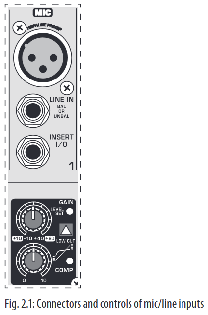
MIC
Each mono input channel offers a balanced microphone input via the XLR connector and also features switchable +48 V phantom power supply for condenser microphones. The XENYX preamps provide undistorted and noise-free gain as is typically known only from costly outboard preamps.
- Please mute your playback system before you activate the phantom power supply to prevent switch-on thumps being directed to your loud speakers. Please also note the instructions in chapter 2.5 «Rear view of X1222USB».
LINE IN
Each mono input also features a balanced line input on a ¼» connector.
Unbalanced devices (mono jacks) can also be connected to these inputs.
- Please remember that you can only use either the microphone or the line input of a channel at any one time. You can never use both simultaneously!
INSERT
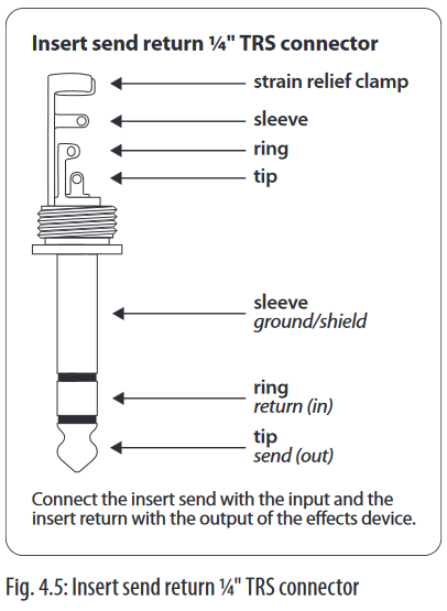
Insert points enable the processing of a signal with dynamic processors or equalizers. They are sourced pre-fader, pre-EQ and pre-aux send. Unlike reverb or other effects devices, whose signals are usually added to the dry signal, dynamic processors are most effective on the complete signal. In this case, aux send paths are a less-than-perfect solution. It is better to interrupt the signal path and insert a dynamic processor and/or equalizer. After processing, the signal is routed back to the console at precisely the same point it left. However, the channel signal path is interrupted only if a plug is inserted into the corresponding jack (stereo phone plug: tip = signal output; ring = return input). All mono input channels are equipped with inserts.
Inserts can also be used as pre-EQ direct outputs, without interrupting the signal path. To this end, you will need a cable fitted with mono phone plugs on the tape machine or effects device end, and a bridged stereo phone plug on the console side (tip and ring connected).
LOW CUT
The mono channels of the mixing consoles have a high-slope LOW CUT filter for eliminating unwanted, low-frequency signal components (80 Hz, 18 dB/octave).
GAIN
Use the GAIN control to adjust the input gain. This control should always be turned fully counter-clockwise whenever you connect or disconnect a signal source to one of the inputs.
The scale has 2 different value ranges: the first value range (+10 to +60 dB) refers to the MIC input and shows the amplification for the signals fed in there.
The second value range (+10 to -40 dB) refers to the line input and shows its sensitivity. The settings for equipment with standard line-level signals (-10 dBV or +4 dBu) look like this: While the GAIN control is turned all the way down, connect your equipment. Set the GAIN control to the external devices’ standard output level. If that unit has an output signal level display, it should show 0 dB during signal peaks. For +4 dBu, turn up GAIN slightly, for -10 dBV a bit more. Tweaking is done using the LEVEL SET LED.
LEVEL SET
This LED lights up when the optimum operating signal level is achieved. During normal use, this LED should only light up during signal peaks.
COMPRESSOR
Each mono channel features a built-in compressor which lowers the dynamic range of the signal and increases its perceived loudness. The loud peaks are squashed down and the quiet sections are boosted.
Turn the COMP knob clockwise to add more compression effect. The adjacent LED with light when the effect is engaged.
Equalizer
All mono input channels include a 3-band equalizer. All bands provide boost or cut of up to 15 dB. In the central position, the equalizer is inactive.
The circuitry of the British EQs is based on the technology used in the best-known top-of-the-line consoles and providing a warm sound without any unwanted side effects. The result are extremely musical equalizers which, unlike simple equalizers, cause no side effects such as phase shifting or bandwidth limitation, even with extreme gain settings of ±15 dB.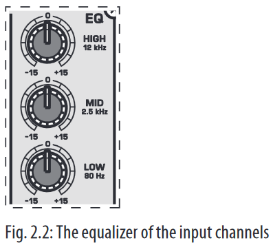
The upper (HIGH) and the lower band (LOW) are shelving filters that increase or decrease all frequencies above or below their cut-off frequency. The cut-off frequencies of the upper and lower band are 12 kHz and 80 Hz respectively. The mid band is configured as a peak filter with a center frequency of 2.5 kHz. Unlike shelving filters, the peak filter processes a frequency range that extends upwards and downwards around its middle frequency.
Aux sends (MON and FX)
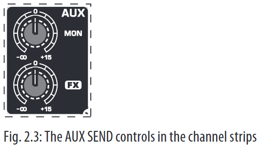
Aux sends take signals via a control from one or more channels and sum these signals to a so-called bus. This bus signal is sent to an aux send connector and then routed, for example, to an active monitor speaker or an external effects device. The return from an external effects device can then be brought back into the console via the aux return connectors.
For situations that require effects processing, the aux sends are usually switched post-fader so that the effects volume in a channel corresponds to the position of the channel fader. If this were not the case, the effects signal of the channel would remain audible even when the fader is turned to zero.
When setting up a monitor mix, the aux sends are generally switched to pre-fader; i.e. they operate independently of the position of the channel fader. Both aux sends are mono, are sourced after the equalizer and offer up to +15 dB gain.
- If you press the MUTE switch of the respective channel, aux sends and returns (MON and FX) are not being muted.
MON
In the X1222USB, aux send 1 (MON) is wired pre-fader and is thus particularly suitable for setting up monitor mixes.
FX
The aux send labeled FX is for feeding external effects devices and is thus set up to be post-fader.
In the X1222USB, the FX send is routed directly to the built-in effects processor. To make sure that the effects processor receives an input signal, you shouldn’t turn this control all the way to the left (-oo). Don’t have the FX MUTE switch pressed, and you should also not have the FX SEND fader pulled down.
Pan, mute switch and channel fader
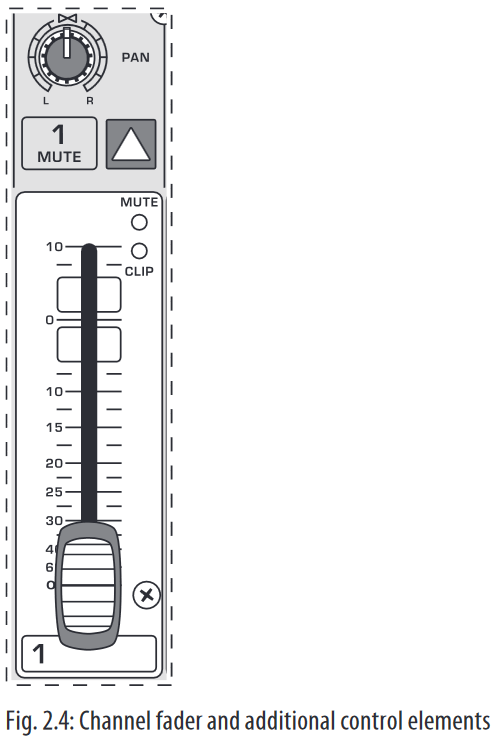
PAN
The PAN control determines the position of the channel signal within the stereo image. This control features a constant-power characteristic, which means the signal is always maintained at a constant level, irrespective of position in the stereo panorama.
MUTE
Use the MUTE switch to mute the channel. This means that the channel signal is no longer present in the main mix. However, the aux sends (MON and FX) remain active.
MUTE LED
The MUTE LED indicates that the relevant channel is muted.
CLIP LED
The CLIP LED lights up when the input signal is driven too high. In this case, lower apparent frequency increase on the channel EQ to avoid distortion. For example, lower the mids and the highs somewhat to emphasize the bass. If you don’t wish to change the EQ settings under any circumstances, try lowering the GAIN control somewhat (counterclockwise).
If you inserted an external effects processor via the insert connector (e.g. a dynamic processor), then you should also control its output signal level. It should not be higher than its input signal level (0 dB).
The channel fader determines the level of the channel signal in the main mix.
Attention: Since the aux path for the effect processor is connected post-fader, the channel fader has to be turned up in order to get this channel’s signal to the effects processor!
Stereo channels
Channel inputs
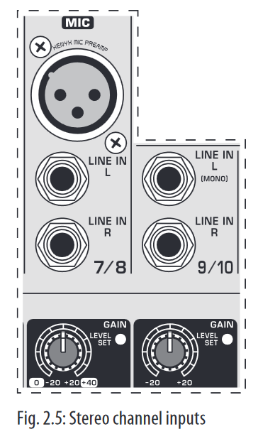
Each stereo channel features two line-level inputs on ¼» connectors for left and right channels. Channels 9/10 and 11/12 can also be used in mono if you only use the connector labeled «L.»
Both channels 5/6 and 7/8 feature an additional balanced XLR input for microphones with available +48 V phantom power.
All stereo channel strips have a GAIN control for level setting. In those channels in which a mic input is present in the channel, the GAIN control has two scales: just like in the mono channels, there is a 0 to +40 dB scale that shows the preamplification of the mic signal; the +20 to -20 dB scale shows the sensitivity for the corresponding input level that is applied to the line input.
Both inputs can also be used with balanced or unbalanced connectors.
Equalizer stereo channels
The equalizer of the stereo channels is, of course, stereo. The filter characteristics and crossover frequencies are the same as those of the mono channels. A stereo equalizer is always preferable to two mono equalizers if frequency correction of a stereo signal is needed. There is often a discrepancy between the settings of the left and the right channels when using separate equalizers.
Aux sends stereo channels
In principle, the aux sends of the stereo channels function in just the same way as those of the mono channels. As aux send paths are always mono, the signal on a stereo channel is first summed to mono before it reaches the aux bus.
Balance, mute switch and channel fader
BAL
The function of the BAL(ANCE) control corresponds to the PAN control in the mono channels.
The balance control determines the relative proportion between the left and right input signals before both signals are routed to the main stereo mix bus.
The MUTE switch, MUTE LED, CLIP LED and channel fader function in the same way as the mono channels.
Connector panel and main section
Whereas it was useful to trace the signal flow from top to bottom in order to gain an understanding of the channel strips, we now look at the mixing console from left to right. The signals are, so to speak, collected from one point on each of the channel strips and then routed to the main section all together.
Monitor send and FX send channels
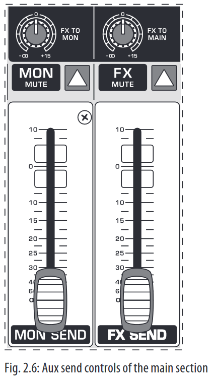
A channel signal is routed to the MON(ITOR) send bus if the MON control is turned up on the corresponding channel.
MON SEND
The aux send control MON SEND acts as master control for the monitor bus and determines the level of the summed signal that is taken from the mixer via the MON SEND connector and that can for example be fed to an amplifier for monitor purposes.
Using the audio signal from this output, you can also feed a subwoofer if you don’t require stage monitors. To this end, you should implement a crossover in your signal path pre-subwoofer and pre-amplifier, so that only low frequencies are fed into the subwoofer. You can achieve the same effect by using the built-in graphical equalizer. Lower all frequencies above 160 Hz and assign the equalizer to «Monitor».
- When you use the MAIN MIX fader to reduce the overall volume, keep in mind that the subwoofer is still receiving a signal!
FX TO MON
You can use this control to insert an effects signal from the built-in effects processor to your monitor mix. Of course, to do this, your effects processor must first receive a signal, i.e. the FX controls in the channel strips must be turned up, and the FX SEND fader (see fig. 2.6) hast to be open.
MON MUTE
If the MON MUTE switch is pressed, the monitor bus is muted, i.e. there is no signal at the MON SEND connector.
FX SEND
The FX SEND fader determines the overall level of the effects bus. Both external effects processors (via the FX SEND connector) and the built-in processor only receive an input signal if this control is open.
FX TO MAIN
Use the FX TO MAIN control to feed the effects signal into the main mix.
If the control is turned all the way to the left, no effects signal can be heard.
FX MUTE
If the FX MUTE switch is pressed, the effects channel is muted, i.e. no signal is present at the FX SEND connector and the effects processor no longer receives an input signal.
Monitor send and FX send connector
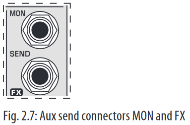
MON SEND
Connect the input of your monitor power amp or an active monitor system here to make the monitor mix audible to the musicians on the stage. The signal mix is created using the channels’ MON controls.
FX SEND
The FX SEND connector outputs the signal you picked up from the individual channels using the FX controls. You can connect this to the input of an external effects device in order to process the FX bus’ master signal. Once an effects mix is created, the processed signal can then be routed from the effects device outputs back into the AUX RETURN connectors.
- If the connected effects processor receives no input signal, the FX MUTE switch is probably pressed and/or the FX SEND control is too low. This also goes for the built-in effects processor.
- Adjust your external effects processor to 100% wet (effects signal only), because the effects signal is added to the main mix along with the «dry» channel signals.
Aux return connectors
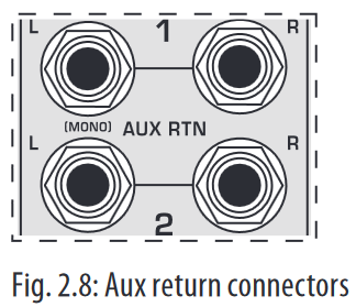
AUX RETURN 1
The AUX RETURN 1 connectors generally serve as the return path for the effects mix generated using the FX send. This is where you connect the output signal of the external effects device. If only the left connector is used, the aux return 1 automatically operates in mono.
- You can also use these connectors as additional line inputs.
AUX RETURN 2
The AUX RETURN 2 connectors are used exactly the same way as the AUX RETURN 1 connectors. If these connectors already function as additional inputs, you can route the effects signal back into the console via a different stereo channel, with the added benefit that the channel EQ can be used to adjust the frequency response of the effects return signal.
- In this instance, the FX control of the channel being used as an effects return should be turned fully counter-clockwise, otherwise feedback problems can occur!
CD/tape return channel, voice canceller and connection socket
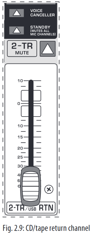
This channel, intended especially for connecting stereo signal sources (CD players, DAT recorders or even sound cards) features a particularly practical feature: the VOICE CANCELLER.
VOICE CANCELLER
Here, you have a filter circuitry that lets you almost entirely remove the vocal portion of a recording. The filter is constructed in such a way that voice frequencies are targeted without majorly affecting the rest of the signal. Additionally, the filter seizes only the middle of the stereo image, exactly there where the vocals are typically located.
Possible applications for the Voice Canceller are obvious: you can very simply stage background music for Karaoke events. Of course, you can also do this at home or at your rehearsal room before you hit the stage. Singers with their own band can practice singing difficult parts using a complete playback from a tape player or a CD, thus minimizing rehearsal time.
STANDBY
If the STANDBY switch is pressed, all input channels with a mic connector (XLR connector) are muted. During breaks or stage conversion, you can prevent noise from entering the sound system via the microphones. Such noise can in the worst-case scenario even irreparably damage loudspeaker membranes. The cool thing about this is that the main mix faders can remain open, so that you can play music from a CD at the same time. Similarly, the faders for the muted channels can also remain in their position.
To bring in other sound sources, you can use the CD/tape inputs, stereo input channels 9 to 12 and the aux return inputs.
CD/TAPE MUTE
Using this switch, the input signal from the CD/tape inputs is muted.
CD/TAPE RET(URN)
This stereo fader assigns the input signal from the CD/tape inputs into the main mix.
CD/TAPE INPUT
The CD/TAPE INPUT RCA connectors are provided for connecting a 2-track machine (e.g. DAT recorder) or also a CD player. They can also be used as stereo line input.
Alternatively, the output signal of a second XENYX or BEHRINGER ULTRALINK PRO MX882 can also be connected. If you connect a hi-fi amplifier with a source selection switch to the CD/TAPE INPUT, you can easily switch between additional sources (e.g. cassette recorder, MD player, sound card etc.).
Using the voice canceller function, you can process all signals being brought into your mixing console via these connectors.
CD/TAPE OUTPUT
These connectors are wired pre graphic EQ and pre XPQ surround function.
They carry the main mix signal (unbalanced), effects mix included. Connect the CD/TAPE OUTPUT to the inputs of your recording device. If you wish to use your mixer solely for recording purposes, the main outputs are also an alternative.
Main mix, main out connectors and headphone connector

MAIN MIX
Use the high-precision quality faders to control the output level of the main mix.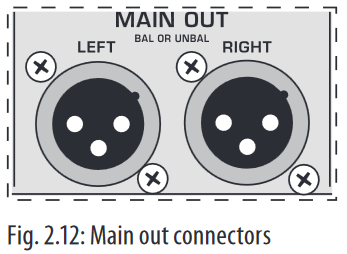
MAIN OUT
The MAIN outputs carry the MAIN MIX signal and are on balanced XLR connectors with a nominal level of +4 dBu. Depending on how you wish to use your mixer and which gear you own, you can connect the following equipment:
Live PA systems:
A stereo dynamics processor (optional), stereo equalizer (optional) and the stereo power amplifier for full-range loud-speakers with passive crossovers.
If you wish to use multi-way loudspeaker systems without an integrated crossover, you have to use an active crossover and several power amplifiers. Often, limiters are already built into active crossovers (e.g. BEHRINGER SUPER-X PRO CX2310 and ULTRADRIVE PRO DCX2496). Active crossovers are implemented directly before the power amplifier, and they divide the frequency range into several segments that are first amplified in the amplifiers and then passed onto the corresponding loudspeakers.
Recording:
For mastering, using a stereo compressor such as the COMPOSER PRO-XL MDX2600 can be recommended. Use it to custom-tailor the dynamic characteristics of your signal to the dynamic range of the recording equipment you are using. The signal is in this case passed on from the compressor into the recorder.
PHONES
The PHONES control adjusts the volume of the headphones connected to the PHONS/CTRL connector. If you connect active monitors or an amplifier, use this connector to adjust the output signal level.
- We would like to draw your attention to the fact that extreme volumes may damage your hearing and/or your headphones or loudspeakers. Turn the MAIN MIX faders and the PHONES control in the main section fully down before you switch on the unit. Always be careful to set the appropriate volume.
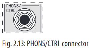
PHONS/CTRL connector
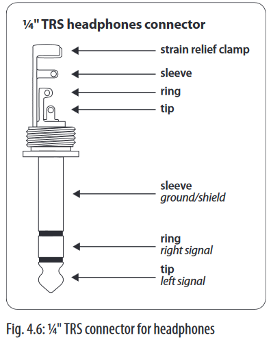
You can connect headphones to this ¼» TRS connector. The connector can also be used for feeding active monitor loudspeakers (or an amplifier) in your control room. For this purpose, the signal is taken directly before it is passed on to the main mix faders.
Level meter and level setting
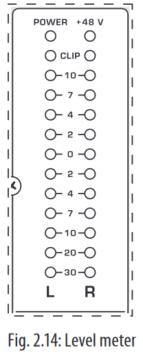
POWER
The blue POWER LED indicates that the device is switched on.
+48 V
The red «+48 V» LED lights up when the phantom power supply is switched on. The phantom power supply is necessary for condenser microphones and is activated using the corresponding switch on the rear of the device.
- Connect microphones before you switch on the phantom power supply. Please do not connect microphones to the mixer (or the stagebox/wallbox) while the phantom power supply is switched on. In addition, the monitor/PA loudspeakers should be muted before you activate the phantom power supply. After switching on, wait approx. one minute to allow for system stabilization.
LEVEL METER/CLIP
The high-precision level meter accurately displays the appropriate signal level.
LEVEL SETTING:
When recording to a digital device, the recorder’s peak meter should not exceed 0 dB. This is because, unlike analog recordings, slightly excessive levels can create unpleasant digital distortion.
When recording to an analog device, the VU meters of the recording machine should reach approx. +3 dB with low-frequency signals (e.g. kick drum). Due to their inertia VU meters tend to display too low a signal level at frequencies above 1 kHz. This is why, for example, a Hi-Hat should only be driven as far as -10 dB. Snare drums should be driven to approx. 0 dB.
- The peak meters of your XENYX display the level virtually independent of frequency. A recording level of 0 dB is recommended for all signal types.
USB input/output
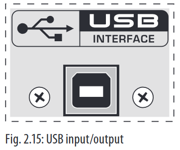
The XENYX mixer line has built-in USB connectivity, allowing stereo signals to be sent to and from the mixer and a computer. The audio sent from the mixer to a computer is identical to the MAIN MIX. Audio being sent to the mixer from a computer can be routed to the main mix with the 2-TR/USB TO MAIN button.
Connect the USB type B plug into the USB jack on the mixer, and the other end into a free USB port on your computer. There are no required drivers, but we recommend that PC users install the included ASIO driver. The driver can also be downloaded from behringer.com.
Graphic 7-band equalizer
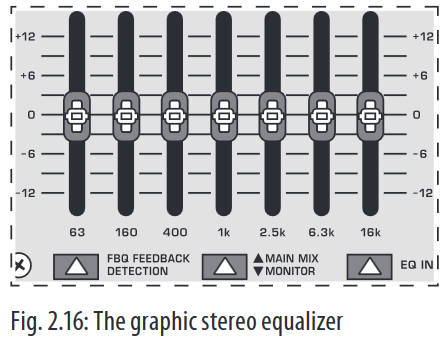
The graphic stereo equalizer allows you to tailor the sound to the room acoustics.
FBQ FEEDBACK DETECTION
The switch turns on the FBQ Feedback Detection System. It uses the LEDs in the frequency band faders to indicate the critical frequencies. On a per-need basis, lower the frequency range in question somewhat in order to avoid feedback. The graphic stereo equalizer has to be turned on in order to use this function.
- Logically, at least one (ideally several) microphone channels have to be open for feedback to occur at all!
Feedback is particularly common when stage monitors («wedges») are concerned, because monitors project sound in the direction of microphones. Therefore, you can also use the FBQ Feedback Detection for monitors by placing the equalizer in the monitor bus (see MAIN MIX/MONITOR).
EQ IN
Use this switch to activate the graphic equalizer. When activated, the fader LEDs will illuminate.
MAIN MIX/MONITOR
This toggles the graphic equalizer between the main mix and the monitor mix. With the switch up (not depressed), the equalizer is active in stereo on the main mix, and inactive on the monitor mix.
When the switch is depressed the equalizer is active in mono on the monitor mix, and inactive on the main mix.
Rear view of X1222USB
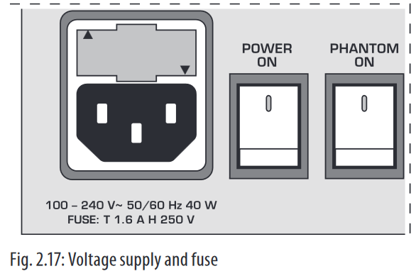
FUSE HOLDER/IEC MAINS RECEPTACLE
The console is connected to the mains via the cable supplied, which meets the required safety standards. Blown fuses must only be replaced by fuses of the same type and rating. The mains connection is made via a cable with IEC mains connector. An appropriate mains cable is supplied with the equipment.
POWER
Use the POWER switch to power up the mixing console. The POWER switch should always be in the «Off» position when you are about to connect your unit to the mains.
To disconnect the unit from the mains, pull out the main cord plug. When installing the product, ensure that the plug is easily accessible. If mounting in a rack, ensure that the mains can be easily disconnected by a plug pull or by an all-pole disconnect switch on or near the rack.
Attention: The POWER switch does not fully disconnect the unit from the mains. Unplug the power cord completely when the unit is not used for prolonged periods of time.
PHANTOM
The PHANTOM switch activates the phantom power supply for the XLR microphone inputs, which is required to operate condenser microphones. The red +48 V LED lights up when phantom power is on. As a rule, dynamic microphones can still be used with phantom power switched on, provided that they are wired in a balanced configuration. In case of doubt, contact the microphone manufacturer!
- Connect microphones before you switch on the phantom power supply. Please do not connect microphones to the mixer (or the stagebox/ wallbox) while the phantom power supply is switched on. In addition, the monitor/PA loudspeakers should be muted before you activate the phantom power supply. After switching on, wait approx. one minute to allow for system stabilization.
You must never use unbalanced XLR connectors (PIN 1 and 3 connected) on the MIC input connectors if you want to use the phantom power supply.
SERIAL NUMBER
Please note the important information on the serial number.
Digital Effects Processor and XPQ Surround Function
Digital effects processor
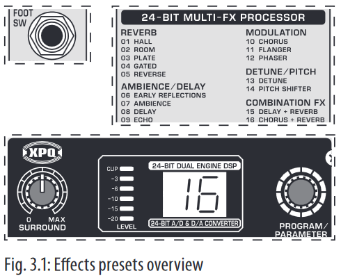
24-BIT MULTI-EFFECTS PROCESSOR
Here you can find a list of all presets stored in the multi-effects processor. This built-in effects module produces high-grade standard effects such as reverb, chorus, flanger, delay and various combination effects. The integrated effects module has the advantage of requiring no wiring. This way, the danger of creating ground loops or uneven signal levels is eliminated at the outset, completely simplifying the handling.
These effect presets are designed to be added to dry signals. If you move the FX TO MAIN control, you mix the channel signal (dry) and the effect signal.
This also goes for mixing effects signals with the monitor mix. The main difference is that the mix ratio is adjusted using the FX TO MON control. Of course, a signal has to be fed into the effects processor via the FX control in the channel strip for both applications.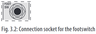
FOOTSWITCH
Connect a standard footswitch to the footswitch connector; use this to switch the effects processor on and off. A flashing dot at the bottom of the display indicates if the effects processor is muted via the footswitch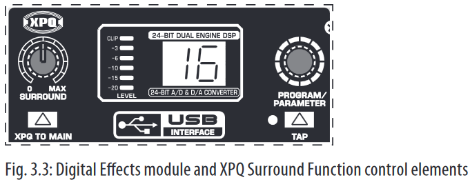
LEVEL
The LED level meter on the effects module should display a sufficiently high level. Take care to ensure that the clip LED only lights up at peak levels. If it is lit constantly, you are overloading the effects processor and this could cause unpleasant distortion. The FX SEND fader determines the level that reaches the effects module.
PROGRAM
You can select the effect preset by turning the PROGRAM control. The display flashes the number of the current preset. To recall the selected preset, press the button; the flashing stops. You can also recall the selected preset using the footswitch.
XPQ surround function
The surround function can be enabled/disabled with the XPQ TO MAIN switch. This is a built-in effect that widens the stereo width, thus making the sound more lively and transparent. Use the SURROUND control to determine the intensity of this effect.
Installation
Rack mounting
The packaging of your mixing console contains two 19″ rack mount brackets which can be installed on the side panels of the console.
Before you can attach the rack mount brackets to the mixing console, you need to remove the screws holding the left and right side panels. Use these screws to fasten the two brackets onto the console, being careful to note that each bracket fits a specific side. With the rack mount brackets installed, you can mount the mixing console in a commercially available 19″ rack. Be sure to allow for proper air flow around the unit, and do not place the mixing console close to radiators or power amps, so as to avoid overheating.
- Only use the screws holding the mixing console side panels to fasten the 19″ rack mounts.
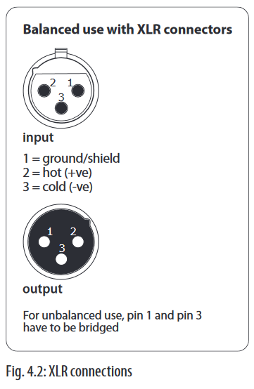
Cable connections
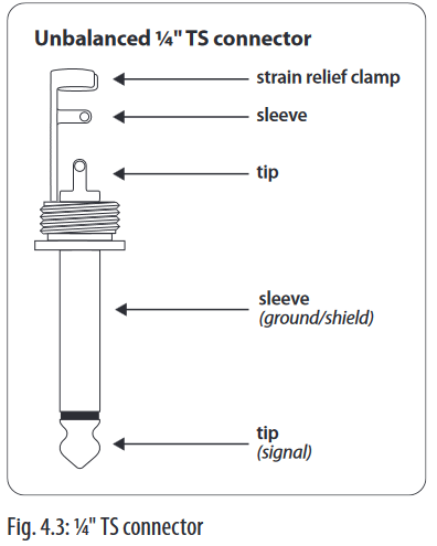
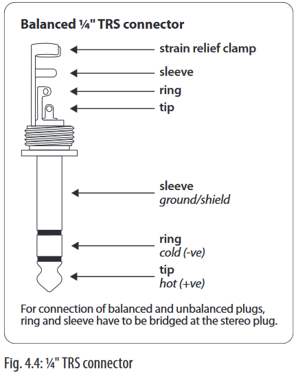
You will need a large number of cables for the various connections to and from the console. The following illustrations show the wiring of these cables. Be sure to use only high-grade cables.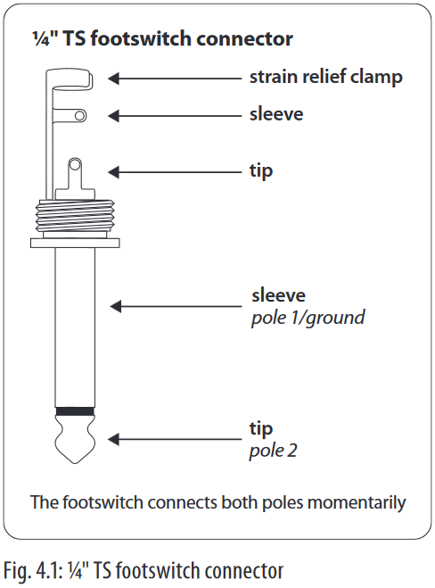
Audio connections
Please use commercial RCA cables to wire the 2-track inputs and outputs.
You can, of course, also connect unbalanced devices to the balanced input/ outputs. Use either mono plugs, or ensure that ring and sleeve are bridged inside the stereo plug (or pins 1 & 3 in the case of XLR connectors).
You must never use unbalanced XLR connectors (pins 1 and 3 connected) on the MIC inputs if you intend to use the phantom power supply.
Specifications
| Mono Inputs | |
| Microphone Inputs (XENYX Mic Preamp) | |
| Type | XLR, electronically balanced, discrete input circuitry |
| Mic E.I.N. (20 Hz — 20 kHz) | |
| @ 0 Ω source resistance | -134 dB / 135.7 dB A-weighted |
| @ 50 Ω source resistance | -131 dB / 133.5 dB A-weighted |
| @ 150 Ω source resistance | -129 dB / 130.5 dB A-weighted |
| Frequency response | <10 Hz — 150 kHz (-1 dB), <10 Hz — 200 kHz (-3 dB) |
| Gain range | +10 to +60 dB |
| Max. input level | +12 dBu @ +10 dB Gain |
| Impedance | approx. 2.6 k Ω balanced |
| Signal-to-noise ratio | 110 dB / 112 dB A-weighted (0 dBu In @ +22 dB Gain) |
| Distortion (THD + N) | 0.005% / 0.004% A-weighted |
| Line Input | |
| Type | ¼» TRS connector, electronically balanced |
| Impedance | approx. 20 kΩ balanced approx. 10 kΩ unbalanced |
| Gain range | -10 to +40 dB |
| Max. input level | +22 dBu @ 0 dB Gain |
| Fade-Out Attenuation (Crosstalk Attenuation) | |
| Main fader closed | 98 dB |
| Channel muted | 85 dB |
| Channel fader muted | 85 dB |
| Frequency Response | |
| Microphone input to main out | |
| <10 Hz — 90 kHz | +0 dB / -1 dB |
| <10 Hz — 160 kHz | +0 dB / -3 dB |
| Stereo Inputs | |
| Channels 5/6, 7/8 | |
| Microphone input | |
| Type | XLR microphone connector, electronically balanced |
| Impedance | approx. 2.6 k Ω balanced |
| Gain range | 0 dB to +40 dB |
| Max. input level | +2 dBu |
| Channels 9/10, 11/12 | |
| Stereo line inputs | |
| Type | 2 x ¼» TRS connector, unbalanced |
| Impedance | approx. 40 kΩ @ 0 dB Gain |
| Gain range | -20 dB to +20 dB |
| Max. input level | +22 dBu @ 0 dB Gain |
| CD/Tape In | |
| Type | RCA connectors |
| Impedance | approx. 10 kΩ |
| Max. input level | +22 dBu |
| EQ Mono Channels | |
| Low | 80 Hz / ±15 dB |
| Mid | 2.5 kHz / ±15 dB |
| High | 12 kHz / ±15 dB |
| Low cut | 80 Hz, 18 dB/oct. |
| EQ Stereo Channels | |
| Low | 80 Hz / ±15 dB |
| Mid | 2.5 kHz / ±15 dB |
| High | 12 kHz / ±15 dB |
| MON/FX Send | |
| Type | ¼» TS connector, unbalanced |
| Impedance | approx. 120 Ω |
| Max. output level | +22 dBu |
| Aux Returns | |
| Type | ¼» TRS connector, unbalanced |
| Impedance | approx. 10 k Ω |
| Max. input level | +22 dBu |
| Main Outputs | |
| Type | XLR, electronically balanced |
| Impedance | approx. 240 Ω balanced approx. 120 Ω unbalanced |
| Max. output level | +28 dBu |
| Headphone Output | |
| Type | ¼» TRS connector, unbalanced |
| Max. output level | +19 dBu / 150 Ω (+25 dBm) |
| CD/Tape Out | |
| Type | RCA connectors |
| Impedance | approx. 1 kΩ |
| Max. output level | +22 dBu |
| DSP | Texas Instruments |
| Converter | 24-bit Sigma-Delta 64/128-times oversampling |
| Sampling rate | 40 kHz |
| USB | |
| Audio | Stereo In/Out |
| Connector | Type B |
| Converter | 16-bit |
| Sample Rate | 48 kHz |
| Main Mix System Data | |
| Noise | |
| Main mix @ -∞, Channel fader -∞ |
-99 dB -101 dB A-weighted |
| Main mix @ 0 dB, Channel fader -∞ |
-84 dB -87 dB A-weighted |
| Main mix @ 0 dB, Channel fader @ 0 dB |
-80 dB -82 dB A-weighted |
| Power Supply | |
| Mains Voltage | 100 — 240 V~, 50 — 60 Hz |
| Power consumption | 40 W |
| Fuse | T 1.6 A H 250 V |
| Mains connection | Standard IEC receptacle |
| Physical | |
| Dimensions (H x W x D) | approx. 3 7/8 x 13 18/32 x 13 5/32″ approx. 97 x 345 x 334 mm |
| Weight (net) | approx. 8.38 lbs. approx. 3.80 kg |
Measuring conditions:
- 1 kHz rel. to 0 dBu; 20 Hz — 20 kHz; line input; main output; unity gain.
- 20 Hz — 20kHz; measured at main output. Channels 1 — 4 unity gain; EQ flat; all channels on main mix; channels 1/3 as far left as possible, channels 2/4 as far right as possible. Reference = +6 dBu.
BEHRINGER is constantly striving to manintain the highest professional standards. As a result of these efforts, modifications may be made from time to time to existing products without prior notice. Specifications and appearance may differ from those listed or illustrated.
Here you can download full pdf version of manual, it may contain additional safety instructions, warranty information, FCC rules, etc.

PT
RU
DE
PL
IT
NL
GR
SE
DK
FI
IMPORTANTE: Leia este documento
antes de utilizar o produto. Deseja mais
informação acerca deste produto?
Consulte o verso deste folheto.
ВНИМАНИЕ: Прочитайте этот
документ перед использованием
устройства. Дополнительную
информацию об устройстве вы
найдете на обратной стороне этого
буклета.
WICHTIG: Lesen sie dieses Dokument,
bevor Sie das Produkt verwenden.
Weitere Informationen zu diesem
Produkt finden Sie auf der Rückseite
dieser Broschüre.
WAŻNE: Przeczytaj niniejszy dokument
przed przystąpieniem do użytkowania.
Szczegółowe informacje dotyczące tego
produktu znajdziesz na odwrocie broszury.
IMPORTANTE: Prima di utilizzare
il prodotto, leggere il presente
documento. Desiderate ricevere
maggiori informazioni su questo
prodotto? Vi rimandiamo al retro del
presente libretto.
BELANGRIJK: lees dit document goed
door voordat u het product in gebruik
neemt. Wilt u meer informatie over dit
product? Kijk dan op de achterpagina
van dit boekje.
ΣΗΜΑΝΤΙΚΟ: Διαβάστε αυτό το έντυπο
πριν από τη χρήση του προϊόντος.
Θέλετε περισσότερες πληροφορίες για
αυτό το προϊόν; Ανατρέξτε στην πίσω
πλευρά του φυλλαδίου.
VIKTIGT: Läs det här informationen
innan produkten används. Önskas mer
information om produkten? Se baksidan
på den här broschyren.
VIGTIGT! Læs dette dokument, før
produktet tages i brug. Vil du have flere
oplysninger om produktet? Se bagsiden
af denne folder.
TÄRKEÄÄ: Lue tämä asiakirja ennen
tuotteen käyttöä. Haluatko lisätietoja
tuotteesta? Katso vihon takasivu.
Instruções de
funcionamento/
segurança
Инструкция по
эксплуатации
и технике
безопасности
Bedienungs-/
Sicherheits-
hinweise
Wskazówki
obsługi/
bezpieczeństwa
Istruzioni di
funzionamento /
sicurezza
Bedienings-/
veiligheids-
voorschriften
Οδηγίες
λειτουργίας/
ασφαλείας
Drifts-/säkerhets-
instruktioner
Betjenings-
og sikkerheds-
instruktioner
Käyttö- ja
turvallisuusohjeet
www.behringer.comA50-00000-00969
X1222USB
X1832USB

-
Contents
-
Table of Contents
-
Bookmarks
Quick Links
User Manual
X1222
Premium 16-Input 2/2-Bus Mixer with XENYX Mic Preamps
& Compressors, British EQs, 24-Bit Multi-FX Processor and
USB/Audio Interface
Related Manuals for Behringer XENYX X1222USB
Summary of Contents for Behringer XENYX X1222USB
-
Page 1
User Manual X1222 Premium 16-Input 2/2-Bus Mixer with XENYX Mic Preamps & Compressors, British EQs, 24-Bit Multi-FX Processor and USB/Audio Interface… -
Page 2: Table Of Contents
4.2 Cable connections …………13 5. Specifications …………14 Thank you Congratulations! In purchasing the BEHRINGER XENYX you have acquired a mixer whose small size belies its incredible versatility and audio performance. The XENYX Series represents a milestone in the development of mixing console technology.
-
Page 3: Important Safety Instructions
A list of authorized resellers can dangerous voltage inside the moving the cart/apparatus be found on BEHRINGER’ s website behringer. com under enclosure — voltage that may be suffi cient to constitute a combination to avoid “Where to Buy”, or you can contact the MUSIC Group offi ce risk of shock.
-
Page 4: Limitation Of Liability
XENYX X1222USB User Manual • connection or operation of the unit in any way “Support” at behringer. com. If your country is not (3) This warranty does not detract from the seller’ s listed, please check if your problem can be dealt with…
-
Page 5: Introduction
(e.g. recorder/crossover/amplifier). may damage your hearing and/or your headphones or loudspeakers. The interface of BEHRINGER mixing consoles is optimized for these tasks, Turn the MAIN MIX faders and the PHONES control in the main section enabling you to easily keep track of the signal path.
-
Page 6: The User’s Manual
Please remember that you can only use either the microphone or the line Should your BEHRINGER dealer not be located in your vicinity, you may directly input of a channel at any one time. You can never use both simultaneously! contact one of our subsidiaries.
-
Page 7: Pan, Mute Switch And Channel Fader
XENYX X1222USB User Manual LOW CUT 2.1.3 Aux sends (MON and FX) The mono channels of the mixing consoles have a high-slope LOW CUT filter for eliminating unwanted, low-frequency signal components (80 Hz, 18 dB/octave). GAIN Use the GAIN control to adjust the input gain. This control should always be turned fully counter-clockwise whenever you connect or disconnect a signal Fig.
-
Page 8: Stereo Channels
XENYX X1222USB User Manual All stereo channel strips have a GAIN control for level setting. In those channels in which a mic input is present in the channel, the GAIN control has two scales: The PAN control determines the position of the channel signal within the stereo just like in the mono channels, there is a 0 to +40 dB scale that shows the image.
-
Page 9
XENYX X1222USB User Manual MON SEND ◊ If the connected effects processor receives no input signal, the FX MUTE switch is probably pressed and/or the FX SEND control The aux send control MON SEND acts as master control for the monitor bus is too low. -
Page 10: Main Mix
The MAIN outputs carry the MAIN MIX signal and are on balanced XLR connectors Alternatively, the output signal of a second XENYX or BEHRINGER ULTRALINK with a nominal level of +4 dBu. Depending on how you wish to use your mixer PRO MX882 can also be connected.
-
Page 11: Graphic 7-Band Equalizer
XENYX X1222USB User Manual Recording: ◊ Connect microphones before you switch on the phantom power supply. Please do not connect microphones to the mixer (or the For mastering, using a stereo compressor such as the COMPOSER PRO-XL MDX2600 stagebox/wallbox) while the phantom power supply is switched on.
-
Page 12: Rear View Of X1222Usb
XENYX X1222USB User Manual FBQ FEEDBACK DETECTION PHANTOM The switch turns on the FBQ Feedback Detection System. It uses the LEDs in the The PHANTOM switch activates the phantom power supply for the XLR microphone frequency band faders to indicate the critical frequencies. On a per-need basis, inputs, which is required to operate condenser microphones.
-
Page 13: Xpq Surround Function
XENYX X1222USB User Manual FOOTSWITCH ¼» TS footswitch connector Connect a standard footswitch to the footswitch connector; use this to switch the strain relief clamp effects processor on and off. A flashing dot at the bottom of the display indicates sleeve if the effects processor is muted via the footswitch.
-
Page 14: Specifications
XENYX X1222USB User Manual 5. Specifications Balanced ¼» TRS connector strain relief clamp Mono Inputs sleeve ring Microphone Inputs (XENYX Mic Preamp) Type XLR, electronically balanced, discrete input circuitry Mic E.I.N. (20 Hz — 20 kHz) sleeve ground/shield source resistance -134 dB / 135.7 dB A-weighted…
-
Page 15
1/3 as far left as possible, channels 2/4 as far right as possible. Reference = +6 dBu. Max. output level +28 dBu BEHRINGER is constantly striving to manintain the highest professional standards. As a result of these efforts, Headphone Output modifications may be made from time to time to existing products without prior notice. Specifications and Type ¼»… -
Page 16
XENYX X1222USB User Manual FEDERAL COMMUNICATIONS COMMISSION COMPLIANCE INFORMATION XENYX X1222USB MUSIC Group Services US Inc. Responsible Party Name: 18912 North Creek Parkway, Address: Suite 200 Bothell, WA 98011, Phone: +1 425 672 0816 Phone/Fax No.: Fax: +1 425 673 7647 XENYX X1222USB complies with the FCC rules as mentioned in the following paragraph:… -
Page 17
We Hear You…
Behringer
XENYX QX1222USB Брошюра
Популярность:
6547 просмотры
Подсчет страниц:
18 страницы
Тип файла:
Размер файла:
5.23 Mb
12-канальный микшер XENYX QX1222USB – это простое решение для сложной звукооператорской работы. Совместимый с электросетями напряжения 100 — 240 V, интуитивно понятный в использовании и надёжный в эксплуатации, этот пульт обеспечивает гибкую маршрутизацию сигнала, поэтапное наложение эффектов и оперативное компьютерное редактирование без подключения дополнительных устройств. Поэтому XENYX QX1222USB позволяет не только получить звук высокого качества, но и многократно уменьшить затраты времени, сил и средств.
Основные секции консоли
В канальной секции пульта расположено 12 канальных разъёмов – 4 монофонических и 4 пары стереофонических, 4 основных микрофонных входа и 2 дополнительных, подключенных к стереоканалам. При использовании специальных wireless-переходников к пульту можно подключить два беспроводных микрофона. Хорошее качество входящего сигнала на микрофонных разъёмах обеспечивается предусилителями, а совместимость с микрофонами различного типа возможна благодаря отключаемому источнику фантомного питания 48 V. Насыщенный и громкий звук в моноканалах достигается использованием настраиваемых компрессоров студийного качества.
Коррекция частотной диаграммы сигнала осуществляется трёхполосными «британскими» эквалайзерами, расположенными на каждом из каналов. Сигналы можно заглушать и подключать динамически, при помощи канальных кнопок mute и solo. Уровень входящих сигналов задаётся логарифмическими фейдерами.
Настройка итогового микса также возможна – для этого предусмотрен семиполосный эквалайзер и фейдеры громкости правого и левого канала. Независимо от них работают фейдеры уровня сигнала на выходах Mon, FX send, USB/2-Track. Для отслеживания статуса главных выходов в главной секции консоли имеется 11-уровневая светодиодная индикация громкости.
Внутри и снаружи
XENYX QX1222USB позволяет значительно модифицировать исходный сигнал как собственными встроенными средствами, так и путём подключения дополнительных устройств. Для редактирования звука первым методом в корпус микшера установлен эффект-процессор KLARK TEKNIK. Он позволяет изменять и сохранять настройки шестнадцати программ с использованием функции Tap, причём для удобства управления эффектами рядом с главной секцией пульта расположен LCD-дисплей. Отдельно вынесены функции детектирования обратной связи, настройки трёхмерного звучания и подавления вокала.
Внешние устройства для редактирования подключаются к разъёмам FX send, Foot SW и 2-Track. Обратно сигнал поступает по входам 2-Track и двум стереофоническим AUX returns. Наконец, редактирование любой сложности можно осуществлять на компьютере, для подключения к которому микшер имеет USB-интерфейс.
CD/TAPE INPUT
The CD/TAPE INPUT RCA connectors are provided for connecting a 2-track machine (e.g. DAT recorder) or also a CD player. They can also be used as stereo line input.
Alternatively, the output signal of a second XENYX or BEHRINGER ULTRALINK PRO MX882 can also be connected. If you connect a hi-fi amplifier with a source selection switch to the CD/TAPE INPUT, you can easily switch between additional sources (e.g. cassette recorder, MD player, sound card etc.).
Using the voice canceller function, you can process all signals being brought into your mixing console via these connectors.
CD/TAPE OUTPUT
These connectors are wired pre graphic EQ and pre XPQ surround function.
They carry the main mix signal (unbalanced), effects mix included. Connect the CD/TAPE OUTPUT to the inputs of your recording device. If you wish to use your mixer solely for recording purposes, the main outputs are also an alternative.
Main mix, main out connectors and headphone connector

MAIN MIX
Use the high-precision quality faders to control the output level of the main mix.
MAIN OUT
The MAIN outputs carry the MAIN MIX signal and are on balanced XLR connectors with a nominal level of +4 dBu. Depending on how you wish to use your mixer and which gear you own, you can connect the following equipment:
Live PA systems:
A stereo dynamics processor (optional), stereo equalizer (optional) and the stereo power amplifier for full-range loud-speakers with passive crossovers.
If you wish to use multi-way loudspeaker systems without an integrated crossover, you have to use an active crossover and several power amplifiers. Often, limiters are already built into active crossovers (e.g. BEHRINGER SUPER-X PRO CX2310 and ULTRADRIVE PRO DCX2496). Active crossovers are implemented directly before the power amplifier, and they divide the frequency range into several segments that are first amplified in the amplifiers and then passed onto the corresponding loudspeakers.
Recording:
For mastering, using a stereo compressor such as the COMPOSER PRO-XL MDX2600 can be recommended. Use it to custom-tailor the dynamic characteristics of your signal to the dynamic range of the recording equipment you are using. The signal is in this case passed on from the compressor into the recorder.
PHONES
The PHONES control adjusts the volume of the headphones connected to the PHONS/CTRL connector. If you connect active monitors or an amplifier, use this connector to adjust the output signal level.
- We would like to draw your attention to the fact that extreme volumes may damage your hearing and/or your headphones or loudspeakers. Turn the MAIN MIX faders and the PHONES control in the main section fully down before you switch on the unit. Always be careful to set the appropriate volume.

PHONS/CTRL connector
You can connect headphones to this ¼» TRS connector. The connector can also be used for feeding active monitor loudspeakers (or an amplifier) in your control room. For this purpose, the signal is taken directly before it is passed on to the main mix faders.
Level meter and level setting

POWER
The blue POWER LED indicates that the device is switched on.
+48 V
The red «+48 V» LED lights up when the phantom power supply is switched on. The phantom power supply is necessary for condenser microphones and is activated using the corresponding switch on the rear of the device.
- Connect microphones before you switch on the phantom power supply. Please do not connect microphones to the mixer (or the stagebox/wallbox) while the phantom power supply is switched on. In addition, the monitor/PA loudspeakers should be muted before you activate the phantom power supply. After switching on, wait approx. one minute to allow for system stabilization.
LEVEL METER/CLIP
The high-precision level meter accurately displays the appropriate signal level.
LEVEL SETTING:
When recording to a digital device, the recorder’s peak meter should not exceed 0 dB. This is because, unlike analog recordings, slightly excessive levels can create unpleasant digital distortion.
When recording to an analog device, the VU meters of the recording machine should reach approx. +3 dB with low-frequency signals (e.g. kick drum). Due to their inertia VU meters tend to display too low a signal level at frequencies above 1 kHz. This is why, for example, a Hi-Hat should only be driven as far as -10 dB. Snare drums should be driven to approx. 0 dB.
- The peak meters of your XENYX display the level virtually independent of frequency. A recording level of 0 dB is recommended for all signal types.
USB input/output

The XENYX mixer line has built-in USB connectivity, allowing stereo signals to be sent to and from the mixer and a computer. The audio sent from the mixer to a computer is identical to the MAIN MIX. Audio being sent to the mixer from a computer can be routed to the main mix with the 2-TR/USB TO MAIN button.
Connect the USB type B plug into the USB jack on the mixer, and the other end into a free USB port on your computer. There are no required drivers, but we recommend that PC users install the included ASIO driver. The driver can also be downloaded from behringer.com.
Graphic 7-band equalizer

The graphic stereo equalizer allows you to tailor the sound to the room acoustics.
FBQ FEEDBACK DETECTION
The switch turns on the FBQ Feedback Detection System. It uses the LEDs in the frequency band faders to indicate the critical frequencies. On a per-need basis, lower the frequency range in question somewhat in order to avoid feedback. The graphic stereo equalizer has to be turned on in order to use this function.
- Logically, at least one (ideally several) microphone channels have to be open for feedback to occur at all!
Feedback is particularly common when stage monitors («wedges») are concerned, because monitors project sound in the direction of microphones. Therefore, you can also use the FBQ Feedback Detection for monitors by placing the equalizer in the monitor bus (see MAIN MIX/MONITOR).
EQ IN
Use this switch to activate the graphic equalizer. When activated, the fader LEDs will illuminate.
MAIN MIX/MONITOR
This toggles the graphic equalizer between the main mix and the monitor mix. With the switch up (not depressed), the equalizer is active in stereo on the main mix, and inactive on the monitor mix.
When the switch is depressed the equalizer is active in mono on the monitor mix, and inactive on the main mix.
Rear view of X1222USB

FUSE HOLDER/IEC MAINS RECEPTACLE
The console is connected to the mains via the cable supplied, which meets the required safety standards. Blown fuses must only be replaced by fuses of the same type and rating. The mains connection is made via a cable with IEC mains connector. An appropriate mains cable is supplied with the equipment.
POWER
Use the POWER switch to power up the mixing console. The POWER switch should always be in the «Off» position when you are about to connect your unit to the mains.
To disconnect the unit from the mains, pull out the main cord plug. When installing the product, ensure that the plug is easily accessible. If mounting in a rack, ensure that the mains can be easily disconnected by a plug pull or by an all-pole disconnect switch on or near the rack.
Attention: The POWER switch does not fully disconnect the unit from the mains. Unplug the power cord completely when the unit is not used for prolonged periods of time.
PHANTOM
The PHANTOM switch activates the phantom power supply for the XLR microphone inputs, which is required to operate condenser microphones. The red +48 V LED lights up when phantom power is on. As a rule, dynamic microphones can still be used with phantom power switched on, provided that they are wired in a balanced configuration. In case of doubt, contact the microphone manufacturer!
- Connect microphones before you switch on the phantom power supply. Please do not connect microphones to the mixer (or the stagebox/ wallbox) while the phantom power supply is switched on. In addition, the monitor/PA loudspeakers should be muted before you activate the phantom power supply. After switching on, wait approx. one minute to allow for system stabilization.
You must never use unbalanced XLR connectors (PIN 1 and 3 connected) on the MIC input connectors if you want to use the phantom power supply.
SERIAL NUMBER
Please note the important information on the serial number.
Digital Effects Processor and XPQ Surround Function
Digital effects processor

24-BIT MULTI-EFFECTS PROCESSOR
Here you can find a list of all presets stored in the multi-effects processor. This built-in effects module produces high-grade standard effects such as reverb, chorus, flanger, delay and various combination effects. The integrated effects module has the advantage of requiring no wiring. This way, the danger of creating ground loops or uneven signal levels is eliminated at the outset, completely simplifying the handling.
These effect presets are designed to be added to dry signals. If you move the FX TO MAIN control, you mix the channel signal (dry) and the effect signal.
This also goes for mixing effects signals with the monitor mix. The main difference is that the mix ratio is adjusted using the FX TO MON control. Of course, a signal has to be fed into the effects processor via the FX control in the channel strip for both applications.
FOOTSWITCH
Connect a standard footswitch to the footswitch connector; use this to switch the effects processor on and off. A flashing dot at the bottom of the display indicates if the effects processor is muted via the footswitch
LEVEL
The LED level meter on the effects module should display a sufficiently high level. Take care to ensure that the clip LED only lights up at peak levels. If it is lit constantly, you are overloading the effects processor and this could cause unpleasant distortion. The FX SEND fader determines the level that reaches the effects module.
PROGRAM
You can select the effect preset by turning the PROGRAM control. The display flashes the number of the current preset. To recall the selected preset, press the button; the flashing stops. You can also recall the selected preset using the footswitch.
XPQ surround function
The surround function can be enabled/disabled with the XPQ TO MAIN switch. This is a built-in effect that widens the stereo width, thus making the sound more lively and transparent. Use the SURROUND control to determine the intensity of this effect.
Installation
Rack mounting
The packaging of your mixing console contains two 19″ rack mount brackets which can be installed on the side panels of the console.
Before you can attach the rack mount brackets to the mixing console, you need to remove the screws holding the left and right side panels. Use these screws to fasten the two brackets onto the console, being careful to note that each bracket fits a specific side. With the rack mount brackets installed, you can mount the mixing console in a commercially available 19″ rack. Be sure to allow for proper air flow around the unit, and do not place the mixing console close to radiators or power amps, so as to avoid overheating.
- Only use the screws holding the mixing console side panels to fasten the 19″ rack mounts.
Cable connections
You will need a large number of cables for the various connections to and from the console. The following illustrations show the wiring of these cables. Be sure to use only high-grade cables.
Audio connections
Please use commercial RCA cables to wire the 2-track inputs and outputs.
You can, of course, also connect unbalanced devices to the balanced input/ outputs. Use either mono plugs, or ensure that ring and sleeve are bridged inside the stereo plug (or pins 1 & 3 in the case of XLR connectors).
You must never use unbalanced XLR connectors (pins 1 and 3 connected) on the MIC inputs if you intend to use the phantom power supply.


Specifications
| Mono Inputs | |
| Microphone Inputs (XENYX Mic Preamp) | |
| Type | XLR, electronically balanced, discrete input circuitry |
| Mic E.I.N. (20 Hz — 20 kHz) | |
| @ 0 Ω source resistance | -134 dB / 135.7 dB A-weighted |
| @ 50 Ω source resistance | -131 dB / 133.5 dB A-weighted |
| @ 150 Ω source resistance | -129 dB / 130.5 dB A-weighted |
| Frequency response | <10 Hz — 150 kHz (-1 dB), <10 Hz — 200 kHz (-3 dB) |
| Gain range | +10 to +60 dB |
| Max. input level | +12 dBu @ +10 dB Gain |
| Impedance | approx. 2.6 k Ω balanced |
| Signal-to-noise ratio | 110 dB / 112 dB A-weighted (0 dBu In @ +22 dB Gain) |
| Distortion (THD + N) | 0.005% / 0.004% A-weighted |
| Line Input | |
| Type | ¼» TRS connector, electronically balanced |
| Impedance | approx. 20 kΩ balanced approx. 10 kΩ unbalanced |
| Gain range | -10 to +40 dB |
| Max. input level | +22 dBu @ 0 dB Gain |
| Fade-Out Attenuation (Crosstalk Attenuation) | |
| Main fader closed | 98 dB |
| Channel muted | 85 dB |
| Channel fader muted | 85 dB |
| Frequency Response | |
| Microphone input to main out | |
| <10 Hz — 90 kHz | +0 dB / -1 dB |
| <10 Hz — 160 kHz | +0 dB / -3 dB |
| Stereo Inputs | |
| Channels 5/6, 7/8 | |
| Microphone input | |
| Type | XLR microphone connector, electronically balanced |
| Impedance | approx. 2.6 k Ω balanced |
| Gain range | 0 dB to +40 dB |
| Max. input level | +2 dBu |
| Channels 9/10, 11/12 | |
| Stereo line inputs | |
| Type | 2 x ¼» TRS connector, unbalanced |
| Impedance | approx. 40 kΩ @ 0 dB Gain |
| Gain range | -20 dB to +20 dB |
| Max. input level | +22 dBu @ 0 dB Gain |
| CD/Tape In | |
| Type | RCA connectors |
| Impedance | approx. 10 kΩ |
| Max. input level | +22 dBu |
| EQ Mono Channels | |
| Low | 80 Hz / ±15 dB |
| Mid | 2.5 kHz / ±15 dB |
| High | 12 kHz / ±15 dB |
| Low cut | 80 Hz, 18 dB/oct. |
| EQ Stereo Channels | |
| Low | 80 Hz / ±15 dB |
| Mid | 2.5 kHz / ±15 dB |
| High | 12 kHz / ±15 dB |
| MON/FX Send | |
| Type | ¼» TS connector, unbalanced |
| Impedance | approx. 120 Ω |
| Max. output level | +22 dBu |
| Aux Returns | |
| Type | ¼» TRS connector, unbalanced |
| Impedance | approx. 10 k Ω |
| Max. input level | +22 dBu |
| Main Outputs | |
| Type | XLR, electronically balanced |
| Impedance | approx. 240 Ω balanced approx. 120 Ω unbalanced |
| Max. output level | +28 dBu |
| Headphone Output | |
| Type | ¼» TRS connector, unbalanced |
| Max. output level | +19 dBu / 150 Ω (+25 dBm) |
| CD/Tape Out | |
| Type | RCA connectors |
| Impedance | approx. 1 kΩ |
| Max. output level | +22 dBu |
| DSP | Texas Instruments |
| Converter | 24-bit Sigma-Delta 64/128-times oversampling |
| Sampling rate | 40 kHz |
| USB | |
| Audio | Stereo In/Out |
| Connector | Type B |
| Converter | 16-bit |
| Sample Rate | 48 kHz |
| Main Mix System Data | |
| Noise | |
| Main mix @ -∞, Channel fader -∞ |
-99 dB -101 dB A-weighted |
| Main mix @ 0 dB, Channel fader -∞ |
-84 dB -87 dB A-weighted |
| Main mix @ 0 dB, Channel fader @ 0 dB |
-80 dB -82 dB A-weighted |
| Power Supply | |
| Mains Voltage | 100 — 240 V~, 50 — 60 Hz |
| Power consumption | 40 W |
| Fuse | T 1.6 A H 250 V |
| Mains connection | Standard IEC receptacle |
| Physical | |
| Dimensions (H x W x D) | approx. 3 7/8 x 13 18/32 x 13 5/32″ approx. 97 x 345 x 334 mm |
| Weight (net) | approx. 8.38 lbs. approx. 3.80 kg |
Measuring conditions:
- 1 kHz rel. to 0 dBu; 20 Hz — 20 kHz; line input; main output; unity gain.
- 20 Hz — 20kHz; measured at main output. Channels 1 — 4 unity gain; EQ flat; all channels on main mix; channels 1/3 as far left as possible, channels 2/4 as far right as possible. Reference = +6 dBu.
BEHRINGER is constantly striving to manintain the highest professional standards. As a result of these efforts, modifications may be made from time to time to existing products without prior notice. Specifications and appearance may differ from those listed or illustrated.
Here you can download full pdf version of manual, it may contain additional safety instructions, warranty information, FCC rules, etc.

PT
RU
DE
PL
IT
NL
GR
SE
DK
FI
IMPORTANTE: Leia este documento
antes de utilizar o produto. Deseja mais
informação acerca deste produto?
Consulte o verso deste folheto.
ВНИМАНИЕ: Прочитайте этот
документ перед использованием
устройства. Дополнительную
информацию об устройстве вы
найдете на обратной стороне этого
буклета.
WICHTIG: Lesen sie dieses Dokument,
bevor Sie das Produkt verwenden.
Weitere Informationen zu diesem
Produkt finden Sie auf der Rückseite
dieser Broschüre.
WAŻNE: Przeczytaj niniejszy dokument
przed przystąpieniem do użytkowania.
Szczegółowe informacje dotyczące tego
produktu znajdziesz na odwrocie broszury.
IMPORTANTE: Prima di utilizzare
il prodotto, leggere il presente
documento. Desiderate ricevere
maggiori informazioni su questo
prodotto? Vi rimandiamo al retro del
presente libretto.
BELANGRIJK: lees dit document goed
door voordat u het product in gebruik
neemt. Wilt u meer informatie over dit
product? Kijk dan op de achterpagina
van dit boekje.
ΣΗΜΑΝΤΙΚΟ: Διαβάστε αυτό το έντυπο
πριν από τη χρήση του προϊόντος.
Θέλετε περισσότερες πληροφορίες για
αυτό το προϊόν; Ανατρέξτε στην πίσω
πλευρά του φυλλαδίου.
VIKTIGT: Läs det här informationen
innan produkten används. Önskas mer
information om produkten? Se baksidan
på den här broschyren.
VIGTIGT! Læs dette dokument, før
produktet tages i brug. Vil du have flere
oplysninger om produktet? Se bagsiden
af denne folder.
TÄRKEÄÄ: Lue tämä asiakirja ennen
tuotteen käyttöä. Haluatko lisätietoja
tuotteesta? Katso vihon takasivu.
Instruções de
funcionamento/
segurança
Инструкция по
эксплуатации
и технике
безопасности
Bedienungs-/
Sicherheits-
hinweise
Wskazówki
obsługi/
bezpieczeństwa
Istruzioni di
funzionamento /
sicurezza
Bedienings-/
veiligheids-
voorschriften
Οδηγίες
λειτουργίας/
ασφαλείας
Drifts-/säkerhets-
instruktioner
Betjenings-
og sikkerheds-
instruktioner
Käyttö- ja
turvallisuusohjeet
www.behringer.comA50-00000-00969
X1222USB
X1832USB

PT
RU
DE
PL
IT
NL
GR
SE
DK
FI
IMPORTANTE: Leia este documento
antes de utilizar o produto. Deseja mais
informação acerca deste produto?
Consulte o verso deste folheto.
ВНИМАНИЕ: Прочитайте этот
документ перед использованием
устройства. Дополнительную
информацию об устройстве вы
найдете на обратной стороне этого
буклета.
WICHTIG: Lesen sie dieses Dokument,
bevor Sie das Produkt verwenden.
Weitere Informationen zu diesem
Produkt finden Sie auf der Rückseite
dieser Broschüre.
WAŻNE: Przeczytaj niniejszy dokument
przed przystąpieniem do użytkowania.
Szczegółowe informacje dotyczące tego
produktu znajdziesz na odwrocie broszury.
IMPORTANTE: Prima di utilizzare
il prodotto, leggere il presente
documento. Desiderate ricevere
maggiori informazioni su questo
prodotto? Vi rimandiamo al retro del
presente libretto.
BELANGRIJK: lees dit document goed
door voordat u het product in gebruik
neemt. Wilt u meer informatie over dit
product? Kijk dan op de achterpagina
van dit boekje.
ΣΗΜΑΝΤΙΚΟ: Διαβάστε αυτό το έντυπο
πριν από τη χρήση του προϊόντος.
Θέλετε περισσότερες πληροφορίες για
αυτό το προϊόν; Ανατρέξτε στην πίσω
πλευρά του φυλλαδίου.
VIKTIGT: Läs det här informationen
innan produkten används. Önskas mer
information om produkten? Se baksidan
på den här broschyren.
VIGTIGT! Læs dette dokument, før
produktet tages i brug. Vil du have flere
oplysninger om produktet? Se bagsiden
af denne folder.
TÄRKEÄÄ: Lue tämä asiakirja ennen
tuotteen käyttöä. Haluatko lisätietoja
tuotteesta? Katso vihon takasivu.
Instruções de
funcionamento/
segurança
Инструкция по
эксплуатации
и технике
безопасности
Bedienungs-/
Sicherheits-
hinweise
Wskazówki
obsługi/
bezpieczeństwa
Istruzioni di
funzionamento /
sicurezza
Bedienings-/
veiligheids-
voorschriften
Οδηγίες
λειτουργίας/
ασφαλείας
Drifts-/säkerhets-
instruktioner
Betjenings-
og sikkerheds-
instruktioner
Käyttö- ja
turvallisuusohjeet
www.behringer.comA50-00000-00969
X1222USB
X1832USB

-
Contents
-
Table of Contents
-
Bookmarks
Quick Links
User Manual
X1222
Premium 16-Input 2/2-Bus Mixer with XENYX Mic Preamps
& Compressors, British EQs, 24-Bit Multi-FX Processor and
USB/Audio Interface
Related Manuals for Behringer XENYX X1222USB
Summary of Contents for Behringer XENYX X1222USB
-
Page 1
User Manual X1222 Premium 16-Input 2/2-Bus Mixer with XENYX Mic Preamps & Compressors, British EQs, 24-Bit Multi-FX Processor and USB/Audio Interface… -
Page 2: Table Of Contents
4.2 Cable connections …………13 5. Specifications …………14 Thank you Congratulations! In purchasing the BEHRINGER XENYX you have acquired a mixer whose small size belies its incredible versatility and audio performance. The XENYX Series represents a milestone in the development of mixing console technology.
-
Page 3: Important Safety Instructions
A list of authorized resellers can dangerous voltage inside the moving the cart/apparatus be found on BEHRINGER’ s website behringer. com under enclosure — voltage that may be suffi cient to constitute a combination to avoid “Where to Buy”, or you can contact the MUSIC Group offi ce risk of shock.
-
Page 4: Limitation Of Liability
XENYX X1222USB User Manual • connection or operation of the unit in any way “Support” at behringer. com. If your country is not (3) This warranty does not detract from the seller’ s listed, please check if your problem can be dealt with…
-
Page 5: Introduction
(e.g. recorder/crossover/amplifier). may damage your hearing and/or your headphones or loudspeakers. The interface of BEHRINGER mixing consoles is optimized for these tasks, Turn the MAIN MIX faders and the PHONES control in the main section enabling you to easily keep track of the signal path.
-
Page 6: The User’s Manual
Please remember that you can only use either the microphone or the line Should your BEHRINGER dealer not be located in your vicinity, you may directly input of a channel at any one time. You can never use both simultaneously! contact one of our subsidiaries.
-
Page 7: Pan, Mute Switch And Channel Fader
XENYX X1222USB User Manual LOW CUT 2.1.3 Aux sends (MON and FX) The mono channels of the mixing consoles have a high-slope LOW CUT filter for eliminating unwanted, low-frequency signal components (80 Hz, 18 dB/octave). GAIN Use the GAIN control to adjust the input gain. This control should always be turned fully counter-clockwise whenever you connect or disconnect a signal Fig.
-
Page 8: Stereo Channels
XENYX X1222USB User Manual All stereo channel strips have a GAIN control for level setting. In those channels in which a mic input is present in the channel, the GAIN control has two scales: The PAN control determines the position of the channel signal within the stereo just like in the mono channels, there is a 0 to +40 dB scale that shows the image.
-
Page 9
XENYX X1222USB User Manual MON SEND ◊ If the connected effects processor receives no input signal, the FX MUTE switch is probably pressed and/or the FX SEND control The aux send control MON SEND acts as master control for the monitor bus is too low. -
Page 10: Main Mix
The MAIN outputs carry the MAIN MIX signal and are on balanced XLR connectors Alternatively, the output signal of a second XENYX or BEHRINGER ULTRALINK with a nominal level of +4 dBu. Depending on how you wish to use your mixer PRO MX882 can also be connected.
-
Page 11: Graphic 7-Band Equalizer
XENYX X1222USB User Manual Recording: ◊ Connect microphones before you switch on the phantom power supply. Please do not connect microphones to the mixer (or the For mastering, using a stereo compressor such as the COMPOSER PRO-XL MDX2600 stagebox/wallbox) while the phantom power supply is switched on.
-
Page 12: Rear View Of X1222Usb
XENYX X1222USB User Manual FBQ FEEDBACK DETECTION PHANTOM The switch turns on the FBQ Feedback Detection System. It uses the LEDs in the The PHANTOM switch activates the phantom power supply for the XLR microphone frequency band faders to indicate the critical frequencies. On a per-need basis, inputs, which is required to operate condenser microphones.
-
Page 13: Xpq Surround Function
XENYX X1222USB User Manual FOOTSWITCH ¼» TS footswitch connector Connect a standard footswitch to the footswitch connector; use this to switch the strain relief clamp effects processor on and off. A flashing dot at the bottom of the display indicates sleeve if the effects processor is muted via the footswitch.
-
Page 14: Specifications
XENYX X1222USB User Manual 5. Specifications Balanced ¼» TRS connector strain relief clamp Mono Inputs sleeve ring Microphone Inputs (XENYX Mic Preamp) Type XLR, electronically balanced, discrete input circuitry Mic E.I.N. (20 Hz — 20 kHz) sleeve ground/shield source resistance -134 dB / 135.7 dB A-weighted…
-
Page 15
1/3 as far left as possible, channels 2/4 as far right as possible. Reference = +6 dBu. Max. output level +28 dBu BEHRINGER is constantly striving to manintain the highest professional standards. As a result of these efforts, Headphone Output modifications may be made from time to time to existing products without prior notice. Specifications and Type ¼»… -
Page 16
XENYX X1222USB User Manual FEDERAL COMMUNICATIONS COMMISSION COMPLIANCE INFORMATION XENYX X1222USB MUSIC Group Services US Inc. Responsible Party Name: 18912 North Creek Parkway, Address: Suite 200 Bothell, WA 98011, Phone: +1 425 672 0816 Phone/Fax No.: Fax: +1 425 673 7647 XENYX X1222USB complies with the FCC rules as mentioned in the following paragraph:… -
Page 17
We Hear You…
Behringer
XENYX QX1222USB Брошюра
Популярность:
6547 просмотры
Подсчет страниц:
18 страницы
Тип файла:
Размер файла:
5.23 Mb
12-канальный микшер XENYX QX1222USB – это простое решение для сложной звукооператорской работы. Совместимый с электросетями напряжения 100 — 240 V, интуитивно понятный в использовании и надёжный в эксплуатации, этот пульт обеспечивает гибкую маршрутизацию сигнала, поэтапное наложение эффектов и оперативное компьютерное редактирование без подключения дополнительных устройств. Поэтому XENYX QX1222USB позволяет не только получить звук высокого качества, но и многократно уменьшить затраты времени, сил и средств.
Основные секции консоли
В канальной секции пульта расположено 12 канальных разъёмов – 4 монофонических и 4 пары стереофонических, 4 основных микрофонных входа и 2 дополнительных, подключенных к стереоканалам. При использовании специальных wireless-переходников к пульту можно подключить два беспроводных микрофона. Хорошее качество входящего сигнала на микрофонных разъёмах обеспечивается предусилителями, а совместимость с микрофонами различного типа возможна благодаря отключаемому источнику фантомного питания 48 V. Насыщенный и громкий звук в моноканалах достигается использованием настраиваемых компрессоров студийного качества.
Коррекция частотной диаграммы сигнала осуществляется трёхполосными «британскими» эквалайзерами, расположенными на каждом из каналов. Сигналы можно заглушать и подключать динамически, при помощи канальных кнопок mute и solo. Уровень входящих сигналов задаётся логарифмическими фейдерами.
Настройка итогового микса также возможна – для этого предусмотрен семиполосный эквалайзер и фейдеры громкости правого и левого канала. Независимо от них работают фейдеры уровня сигнала на выходах Mon, FX send, USB/2-Track. Для отслеживания статуса главных выходов в главной секции консоли имеется 11-уровневая светодиодная индикация громкости.
Внутри и снаружи
XENYX QX1222USB позволяет значительно модифицировать исходный сигнал как собственными встроенными средствами, так и путём подключения дополнительных устройств. Для редактирования звука первым методом в корпус микшера установлен эффект-процессор KLARK TEKNIK. Он позволяет изменять и сохранять настройки шестнадцати программ с использованием функции Tap, причём для удобства управления эффектами рядом с главной секцией пульта расположен LCD-дисплей. Отдельно вынесены функции детектирования обратной связи, настройки трёхмерного звучания и подавления вокала.
Внешние устройства для редактирования подключаются к разъёмам FX send, Foot SW и 2-Track. Обратно сигнал поступает по входам 2-Track и двум стереофоническим AUX returns. Наконец, редактирование любой сложности можно осуществлять на компьютере, для подключения к которому микшер имеет USB-интерфейс.
5
XENYX X1222USB User Manual
1.2 The user’s manual
The user’s manual is designed to give you both an overview of the controls, as
well as detailed information on how to use them. In order to help you understand
the links between the controls, we have arranged them in groups according to
their function.
1.3 Before you get started
1.3.1 Shipment
Your mixing console was carefully packed in the factory to guarantee safe
transport. Nevertheless, we recommend that you carefully examine the
packaging and its contents for any signs of physical damage, which may have
occurred during transit.
◊
If the unit is damaged, please do NOT return it to us, but notify your
dealer and the shipping company immediately, otherwise claims for
damage or replacement may not be granted.
1.3.2 Initial operation
Be sure that there is enough space around the unit for cooling purposes and to
avoid over-heating. Please do not place your mixing console on high-temperature
devices such as radiators or power amps. The console is connected to the mains
via the supplied power cable. The console meets the required safety standards.
Blown fuses must only be replaced by fuses of the same type and rating.
◊
Please note that all units must be properly grounded. For your own
safety, you should never remove any ground connectors from electrical
devices or power cables, or render them in operative.
◊
Please ensure that only qualified people install and operate the
mixing console. During installation and operation, the user must have
sufficient electrical contact to earth, otherwise electrostatic discharges
might affect the operation of the unit.
1.3.3 Online registration
Please do remember to register your new BEHRINGER equipment right after your
purchase by visiting behringer.com (alternatively behringer.de) and kindly read
the terms and conditions of our warranty carefully.
Should your BEHRINGER product malfunction, our goal is to have it repaired as
quickly as possible. To arrange for warranty service, please contact the retailer
from whom the equipment was purchased. Should your BEHRINGER dealer not
be located in your vicinity, you may directly contact one of our subsidiaries.
Corresponding contact information is included in the original equipment
packaging (Global Contact Information/European Contact Information).
Should your country not be listed, please contact the distributor nearest
you. A list of distributors can be found in the support area of our website
(behringer.com).
Registering your purchase and equipment with us helps us process your repair
claims quicker and more efficiently.
Thank you for your cooperation!
2. Control Elements and Connectors
This chapter describes the various control elements of your mixing console.
All controls, switches and connectors will be discussed in detail.
2.1 Mono channels
2.1.1 Microphone and line inputs
Fig. 2.1: Connectors and controls of mic/line inputs
MIC
Each mono input channel offers a balanced microphone input via the XLR
connector and also features switchable +48 V phantom power supply for
condenser microphones. The XENYX preamps provide undistorted and noise-free
gain as is typically known only from costly outboard preamps.
◊
Please mute your playback system before you activate the phantom
power supply to prevent switch-on thumps being directed to your
loud speakers. Please also note the instructions in chapter 2.5
“Rear view of X1222USB”.
LINE IN
Each mono input also features a balanced line input on a ¼» connector.
Unbalanced devices (mono jacks) can also be connected to these inputs.
◊
Please remember that you can only use either the microphone
or the line input of a channel at any one time. You can never use
both simultaneously!
INSERT
Insert points enable the processing of a signal with dynamic processors or
equalizers. They are sourced pre-fader, pre-EQ and pre-aux send. Unlike reverb
or other effects devices, whose signals are usually added to the dry signal,
dynamic processors are most effective on the complete signal. In this case,
aux send paths are a less-than-perfect solution. It is better to interrupt the
signal path and insert a dynamic processor and/or equalizer. After processing,
the signal is routed back to the console at precisely the same point it left.
However, the channel signal path is interrupted only if a plug is inserted into the
corresponding jack (stereo phone plug: tip = signal output; ring = return input).
All mono input channels are equipped with inserts.
Inserts can also be used as pre-EQ direct outputs, without interrupting the signal
path. To this end, you will need a cable fitted with mono phone plugs on the tape
machine or effects device end, and a bridged stereo phone plug on the console
side (tip and ring connected).
Краткое содержание страницы № 1
Small Format Mixers
XENYX X2442USB / X2222USB
X1832USB / X1622USB
X1222USB / X1204USB / 1204USB
XENYX—Premium Mixer with
XENYX Mic Preamps & Compressors,
British EQs, 24-Bit Multi-FX Processor
and USB/Audio Interface
Premium ultra-low noise,
You’ve got the talent. You’re brimming their own, even when compared to the
high headroom analog mixer
with creativity. And you’re ready to get most expensive stand-alone mic preamps.
your message out to the masses. But XENYX preamps offer a staggeri
Краткое содержание страницы № 2
Page 2 of 17 One-knob Compression Recording Bliss XENYX X2442USB Ask professional sound engineers There was a time when the recording X2222USB / X1832USB what their favorite piece of external process called for lots and lots processing gear is and the majority of expensive gear, which meant the X1622USB / X1222USB response will be virtually unanimous— average musician had to buy time at a X1204USB / 1204USB dynamic compression. What is recording studio—and that time was compression? We’re
Краткое содержание страницы № 3
Page 3 of 17 XENYX X2442USB X2222USB / X1832USB X1622USB / X1222USB X1204USB / 1204USB 1204USB X1204USB X1222USB X1622USB X1832USB X2222USB X2442USB Mic Preamps 4 4 6 4 6 8 10 Stereo Channels 2 2 4 4 4 4 4 Aux Sends 2 2 2 2 3 3 4 Stereo Aux Returns 2 2 2 2 2 3 4 Phantom Power ✓ ✓ ✓ ✓ ✓ ✓ ✓ Channel Inserts — — 4 4 6 8 8 3-band 3-band 3-band 3-band Mono Channel EQ 3-band 3-band 3-band semi-parametic mid semi-parametic mid semi-parametic mid semi-parametic mid Compressors 4 4 4 4 6 8 10 Ste
Краткое содержание страницы № 4
Page 4 of 17 XENYX X2442USB X2222USB / X1832USB X1622USB / X1222USB X1204USB / 1204USB Multi-FX Processor Preset Chart No. Effect PROGRAM Min. value Max. value Default TAP Min. value Max. value Default TAP LED Reverb 01 HALL Reverb time 01 (approx. 1.0 sec.) 10 (approx. 8.0 sec.) 03 Brilliance oF on on off/on lighting 02 ROOM Reverb time 01 (approx. 0.5 sec.) 10 (approx. 4.0 sec.) 04 Brilliance oF on oF off/on lighting 03 PLATE Reverb time 01 (approx. 0.5 sec.) 10 (approx. 5.0 sec.) 03 Brillia
Краткое содержание страницы № 5
Page 5 of 17 all mono channels feature our “one 1204USB knob” studio-grade compressor and two XENYX X2442USB Perfect for a small live-performance Aux Sends (one each pre- and post-fader). X2222USB / X1832USB mixer, as well as home-based recording Two stereo Aux Returns are included setup, the 1204USB provides four mono X1622USB / X1222USB for use with external FX modules. channels with premium XENYX mic The built-in USB audio interface provides X1204USB / 1204USB preamps, neo-classic
Краткое содержание страницы № 6
Page 6 of 17 delay, pitch shifter and multi-effects. X1204USB User-definable parameters include reverb XENYX X2442USB The compact X1204USB mixer takes time and brilliance, delay room size and X2222USB / X1832USB the 1204USB up a notch, providing repetitions, modulation depth and speed, all the same great features, plus our X1622USB / X1222USB and much more. Time-based functions new 24-bit, dual engine FX processor, can be addressed via a handy Tap button. X1204USB / 1204USB with 16 ed
Краткое содержание страницы № 7
Page 7 of 17 graphic EQ, which can be assigned to X1222USB the main or monitor buses, and our XENYX X2442USB The X1222USB ups the ante with six proprietary FBQ Feedback Detection X2222USB / X1832USB mono mic inputs. These two additional System. Other features include full-sized channels can also be used for stereo X1622USB / X1222USB faders for MON and FX SENDs, our XPQ 3D line-level devices, such as keyboards or stereo surround effect (creates a broader, X1204USB / 1204USB sound modu
Краткое содержание страницы № 8
Page 8 of 17 XENYX X2442USB X2222USB / X1832USB X1622USB / X1222USB X1204USB / 1204USB XENYX X1222USB Live/Recording Setup Acoustic Electric Guitar Guitar B412DSP Loudspeakers DI100 Laptop XM8500 Mics HPM1000 Keyboard XENYX X1222USB E-Drums
Краткое содержание страницы № 9
Page 9 of 17 enhanced fine-tuning via 4-band EQ, X1622USB which is extremely handy for adjusting XENYX X2442USB The X1622USB features four XENYX-fueled critical keyboard midrange frequencies. X2222USB / X1832USB mic inputs with channel Inserts, “one Aux 1 Sends are switchable (pre- or knob” compressors and 3-band British- X1622USB / X1222USB post-fader) and individual channels style EQs with a sweepable, can be assigned to two subgroups for X1204USB / 1204USB semi-parametric mid fr
Краткое содержание страницы № 10
Page 10 of 17 XENYX X2442USB X2222USB / X1832USB X1622USB / X1222USB X1204USB / 1204USB X1622USB Rear Panel Sub 1 & 2 Control Room IEC power Power Phantom Power Main Outputs, Outputs, ¼» TS USB/Audio Out, ¼» TS Channel 1-4 socket switch switch XLR balanced unbalanced Interface port unbalanced Inserts XENYX X1622USB Recording Setup B3031A Active Studio Monitors Laptop Acoustic Electric Guitar Guitar DI100 USB In/Out CTRL Out L CTRL Out R B-2 PRO HPS3000 Keyboard Drum Machine XENYX X1622USB
Краткое содержание страницы № 11
Page 11 of 17 in conjunction with the FBQ feedback X1832USB detection circuitry to eliminate annoying XENYX X2442USB Building on the feature set of the mic squeals. Other features include X2222USB / X1832USB X1622USB, the X1832USB comes with full-sized faders for MON and FX SENDs, two additional mic strips (including X1622USB / X1222USB along with our proprietary XPQ 3D stereo channel inserts), for a total of six XENYX surround effect and Voice Canceller. X1204USB / 1204USB mic pream
Краткое содержание страницы № 12
Page 12 of 17 XENYX X2442USB X2222USB / X1832USB X1622USB / X1222USB X1204USB / 1204USB X1832USB Rear Panel Main Outputs, IEC power Power Phantom Main Outputs, ¼» TS Sub 1 & 2 Outputs, USB/Audio Control Room Out, Channel 1-6 socket switch Power switch XLR balanced unbalanced ¼» TS unbalanced Interface port ¼» TS unbalanced Inserts XENYX X1832USB Live/Recording Setup B412DSP Loudspeakers Electric Acoustic Bass Guitar Guitar Guitar Laptop DI100 Main Out L V-AMP 3 Main Out R XM8500 Mics HPS30
Краткое содержание страницы № 13
Page 13 of 17 the X2222USB, plus four stereo line-level X2222USB channels, two convenient mix subgroups XENYX X2442USB How about eight XENYX mic channels and onboard 24-bit digital FX processing, X2222USB / X1832USB with inserts, dedicated compressors, with dual user-addressable parameter 3-band EQ with semi-parametric mids X1622USB / X1222USB controls. All this and more enclosed in a and three Aux Sends? You get all that with rack-ready, roadworthy steel chassis. X1204USB / 1204USB X2
Краткое содержание страницы № 14
Page 14 of 17 XENYX X2442USB X2222USB / X1832USB X1622USB / X1222USB X1204USB / 1204USB X2222USB Rear Panel IEC power Control Room Out, USB/Audio socket Power switch ¼» TS unbalanced Interface port Phantom Power Main Main Outputs, Sub 1 & 2 Outputs, Channel 1-8 switch Outputs, XLR ¼» TS ¼» TS unbalanced Inserts balanced unbalanced XENYX X2222USB Recording Setup E-Drums Electric Acoustic Electric Guitar Guitar Guitar Laptop USB In/Out DI100 V-AMP 3 CTRL Out LCTRL Out R B-2 PRO Mics B3031
Краткое содержание страницы № 15
Page 15 of 17 for connecting graphic equalizers X2442USB or compressor/limiters); and eight XENYX X2442USB The “Big Daddy” of the USB Series is Direct Outs and Sub Outs for analog X2222USB / X1832USB the X2442USB with its 10 state-of-the- recording purposes. art, XENYX-powered mic inputs, four X1622USB / X1222USB No matter what your audio mixing stereo channels, four Aux Sends and X1204USB / 1204USB needs are, BEHRINGER USB Series mixers four stereo Aux Returns, and our easy provide
Краткое содержание страницы № 16
L Overhead Mic R Overhead Mic Snare Mic Kick Mic Page 16 of 17 XENYX X2442USB X2222USB / X1832USB X1622USB / X1222USB X1204USB / 1204USB X2442USB Rear Panel Channel 1-8 USB/Audio Aux Sends 1-4, FX Out, ¼» TS FX Footswitch Direct Outputs, Interface port ¼» TS unbalanced unbalanced jack ¼» TS unbalanced IEC power Power Phantom Main Outputs, Main Outputs, Main Inserts, Control Room Sub 1-8 Outputs, Stereo Aux socket switch Power switch XLR balanced ¼» TS unbalanced ¼» TS unbalanced Out,
Краткое содержание страницы № 17
Page 17 of 17 XENYX X2442USB X2222USB / X1832USB X1622USB / X1222USB X1204USB / 1204USB Specifications Mono Inputs CD/Tape In Control Room Output Microphone inputs (XENYX Mic preamp) Type RCA connector Type ¼» TS connector, unbalanced Type XLR connector, electronically Impedance 10 k Ohms Impedance 120 Ohms balanced, discrete input circuit Max. input level +22 dBu Max. output level +22 dBu Mic E.I.N.1 (20 Hz — 20 kHz) Equalizer 3-band Phones Output @ 0 Ω source resistance -134 dB 135.
