
- Manuals
- Brands
- Grundfos Manuals
- Control Unit
- CU 301
- Installation and operating instructions manual
-
Contents
-
Table of Contents
-
Troubleshooting
-
Bookmarks
Quick Links
GRUNDFOS INSTRUCTIONS
CU 301
Installation and operating instructions
Related Manuals for Grundfos CU 301
Summary of Contents for Grundfos CU 301
-
Page 1
GRUNDFOS INSTRUCTIONS CU 301 Installation and operating instructions… -
Page 2: Limited Warranty
Products which are sold but not manufactured by Grundfos are subject to the warranty provided by the manu- facturer of said products and not by Grundfos’ warranty. Grundfos will not be liable for damage or wear to products caused by abnormal operating conditions, accident, abuse, misuse, unauthorized alteration or repair, or if the product was not installed in accordance with Grundfos’ printed installation and operating instructions.
-
Page 3
CU 301 Installation and operating instructions… -
Page 4: Table Of Contents
5.3.1 Sensor 5.3.2 Choice of sensor 5.3.3 Maximum pressure setting 5.3.4 Automatic restart 5.3.5 Dry-running stop 5.3.6 Maximum speed 5.3.7 Cut-in speed 5.3.8 Buttons on the CU 301 5.3.9 Indication of pump operation 5.3.10 Number Print Troubleshooting Service Technical data Electrical connection 8.1.1 Mains supply…
-
Page 5: Constant-Pressure Control
1. Constant-pressure control CU 301 The control unit CU 301 is for use only with Grundfos CU 301 SQE pumps incorporating electronic power factor correction (PFC). 1.1 Description The system maintains a constant pressure within the maximum pump performance in spite of a varying water consumption.
-
Page 6
Flow detection The pump starts as a consequence of During pump operation, i.e. when water is con- sumed, the CU 301 will adjust the pump speed to • a high flow or maintain a constant pressure. In order to stop the •… -
Page 7: System Sizing
22 SQE-80 system pressure. 22 SQE-120 Comment: If this is not fulfilled, the pressure may fall below the pressure set on the CU 301. 22 SQE-160 Maximum head at rated flow and minimum head at 22 SQE-190 no flow can be found in the following sections.
-
Page 8: Positioning The Pressure Sensor
1.6 Precharge pressure setting The CU 301 is designed to work with a 2 gal. dia- phragm tank. The precharge pressure of the diaphragm tank must be set to 70% of the pressure setting in order to use the tank to the limit of its capacity.
-
Page 9: Operating Functions
2.3 Pressure setting flashing ing with the R100. The two arrow buttons on the CU 301 front are used for the pressure setting, see fig. 10. * If the On/Off button has been used to stop the pump, this button must also be used for restarting.
-
Page 10: Button Locking
The alarm functions indicated on the Setting range: 40-100 psi. CU 301 front are described in the following sections. Arrow-up button 3.1 Service alarm When this button is pressed, the system pressure If one or more factory-set alarm values are setting is increased in steps of 10 psi.
-
Page 11: Dry-Running Protection
5 seconds, and the motor speed is within 1,000 rpm of the maximum speed setting as defined in the section 5.3.6, the CU 301 stops the pump and declares a dry-running alarm. When the motor is stopped, the dry-running indicator light is permanently on, see fig.
-
Page 12: Position Of Leds
Permanent red light when the supply voltage is out of range, see section Voltage alarm *) 8. Technical data. Permanent red light when communication between the CU 301 and the No contact to pump *) pump is impossible. *) Press the On/Off button to reset the alarm indication.
-
Page 13: Cu 301 With R100
The R100 communicates via infrared light. During communication, there must be visual contact between the CU 301 and the R100. The best visual contact between the two units is obtained by pointing the R100 at the lower arrow button or by removing the front cover and pointing the R100 at the right side of the CU 301, see fig.
-
Page 14: Menu Overview
0. GENERAL 1. OPERATION 2. STATUS 3. INSTALLATION 5.3.1 5.2.1 5.1.1 5.1.2 5.2.2 5.3.2 5.2.3 5.1.3 5.3.3 5.1.3 5.2.4 5.3.4 5.3.5 5.2.5 5.2.6 5.3.6 5.3.7 5.3.8 5.3.9 5.3.10 Fig. 16 Menu overview…
-
Page 15: Menu Operation
5.1 Menu OPERATION 5.1.3 Alarm The OPERATION menu for the CU 301 offers the possibility of setting and reading operating parame- ters. Factory settings are marked in bold-faced type under each individual display. 5.1.1 Pressure setting This display shows the current alarm status.
-
Page 16: Menu Status
5.2 Menu STATUS 5.2.3 Speed The STATUS menu for the CU 301 provides operat- ing data about pump/motor and sensor. It is not pos- sible to change or set values in this menu. When [OK] is pressed continuously in this display, the displayed value is being updated.
-
Page 17: Operating Hours And Number Of Starts
• Sensor output signal: «–» (not active), 0-20 mA, The setting of this display overrules the possibility of using the arrow button on the CU 301 front to 4-20 mA, 0-10 V, 2-10 V. increase the pressure to a setting above the •…
-
Page 18: Automatic Restart
5.3.4 Automatic restart Relation to other displays The actual pump power input can be read in display 5.2.5 Power input and power consumption. If the maximum pump speed has been reduced in display 5.3.6 Maximum speed, the dry-running stop value must be changed. 5.3.6 Maximum speed Set the automatic restart time from stop, caused by an alarm, to restart attempt.
-
Page 19: Buttons On The Cu 301
• Running light • Constant light. 5.3.10 Number Allocate a number to the CU 301 and the pump con- nected. The CU 301 and the pump must have the same number. The CU 301 control unit communicates with the SQE…
-
Page 20: Print
6. Print The actual data in the R100 can be printed on a Hewlett-Packard printer type HP82240B. Navigate the R100 to the print menu and point the R100 at the IR sensor of the printer and press [OK]. The following information will be printed:…
-
Page 21: Troubleshooting
• No contact to pump. To identify the cause of the service alarm, it is necessary to remove the front cover from the CU 301 or use the R100. Fit the front cover as shown in fig. 18 to avoid disconnecting the multi-core cable.
-
Page 22
If the pump has not started yet, proceed as follows: • Press the On/Off button for 5 seconds. If the pump starts, the CU 301 or the sensor may be defective. Note: The pressure is not controlled and may rise to a high level. -
Page 23
If the pump has already worked satisfactorily with a cates «No contact to MSE 3. CU 301 or a CU 300, the motor can be expected to be pump». an MSE 3. There is no technical way of determining the motor type. -
Page 24
7. The CU 301 indi- a) The supply voltage is Check — possibly over a period of time — that the supply cates «Overvoltage» unstable or outside voltage is according to the values below. or «Undervoltage». the voltage range • Motor type 0.5 hp = 198-315 V specified for the in- •… -
Page 25: Technical Data
100 mA. Disconnect the sensor in order to determine if it is de- fective. Replace defective sensor. No: The load is OK, but the CU 301 sensor input may be defective. 14. The pump is operat- a) No communication. Check that the LED «No contact to pump» is on.
-
Page 26: Electrical Connection
SQE-NE SQE-NE SQE-NE All models 0.5 hp 0.75 hp 1.0 hp 1.5 hp Sensor defective 4-20 mA (the value is stored in the CU 301) Overload 5.2 A 8.4 A 11.2 A 12 A 11 A Stop limit: Stop limit:…
-
Page 27: Mains Supply
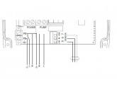
POWER PUMP Fig. 20 Electrical connection of the CU 301 In situations where multiple CU 301 pump power Legend cables are run parallel in wiring trays or conduit and less than 10-12 inches apart, the possibility for Pos. Description undesired communication between units exists.
-
Page 28: Pressure Sensor Voltage Chart
9. Pressure sensor voltage chart Voltage to pressure chart for CU 301 pressure sensors. Measure the DC voltage between «SENSOR IN» and «SENSOR GND». Voltages lower than 2 or higher than 10 indicate an incorrectly wired or a faulty sensor.
-
Page 29: Disposal
This product or parts of it must be disposed of in an environmentally sound way: 1. Use the public or private waste collection service. 2. If this is not possible, contact the nearest Grundfos company or service workshop. Subject to alterations.
-
Page 30
U.S.A. Canada Mexico GRUNDFOS Pumps Corporation GRUNDFOS Canada Inc. Bombas GRUNDFOS de Mexico 17100 West 118th Terrace 2941 Brighton Road S.A. de C.V. Olathe, Kansas 66061 Oakville, Ontario Boulevard TLC No. 15 Phone: +1-913-227-3400 L6H 6C9 Parque Industrial Stiva Telefax: +1-913-227-3500… -
Page 31
Being responsible is our foundation Thinking ahead makes it possible Innovation is the essence 5/06 L-SP-TL-019 www.grundfos.com…
- Manuals
- Brands
- Grundfos Manuals
- Water Pump
- CU 301
- Installation and operating instructions manual
-
Contents
-
Table of Contents
-
Bookmarks
Quick Links
GRUNDFOS INSTRUCTIONS
CU 301
Installation and operating instructions
CU 301
Installation and operating instructions
(all available languages)
http://net.grundfos.com/qr/i/99406808
Related Manuals for Grundfos CU 301
Summary of Contents for Grundfos CU 301
-
Page 1
GRUNDFOS INSTRUCTIONS CU 301 Installation and operating instructions CU 301 Installation and operating instructions (all available languages) http://net.grundfos.com/qr/i/99406808… -
Page 3
CU 301 English (GB) Installation and operating instructions ……..4 Español (ES) -
Page 4: Table Of Contents
Setting the product … . . 18 Grundfos installation and operating instructions, CU 301 with Grundfos GO Remote ..18 safety instructions and service instructions. Status ….. 18 Settings .
-
Page 5: Installing The Product
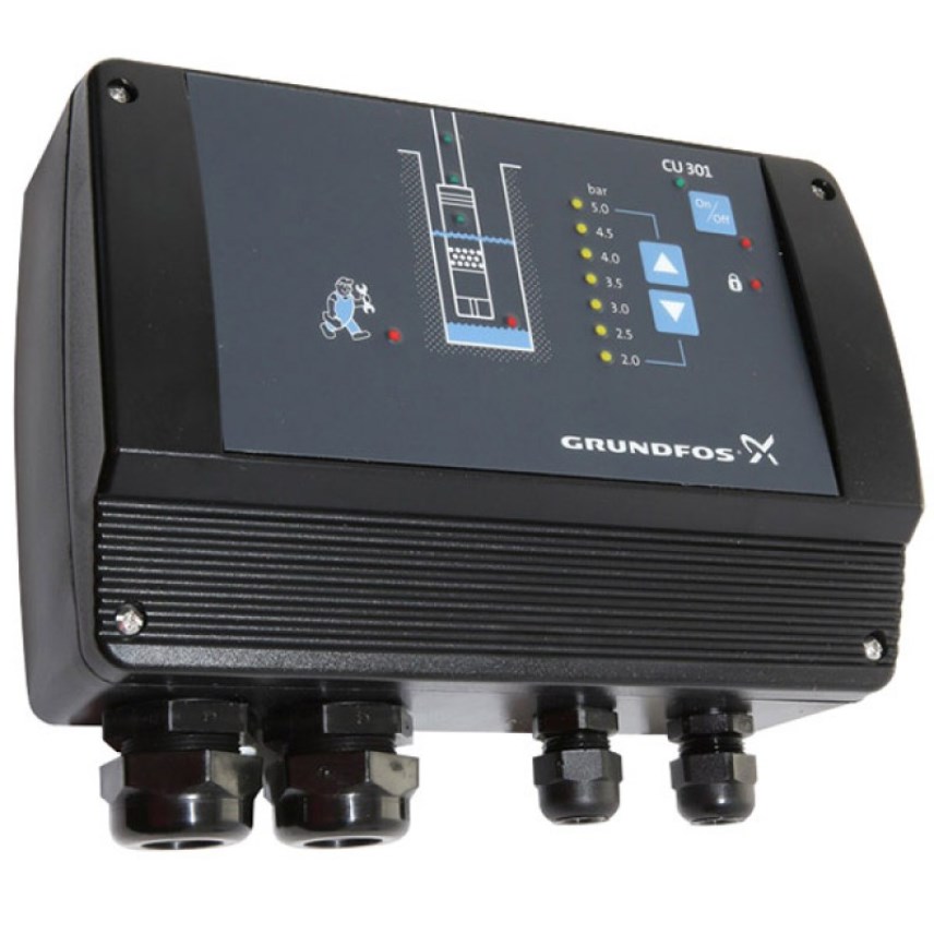
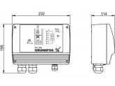
The user or the installer is responsible for correct earthing and protection 104.5 104.5 according to local regulations. Dimensions CU 301 is supplied with special gaskets for the Pg cable entries. The special gaskets are suitable for flat cables and single-core cables.
-
Page 6: Electrical Connection
(PE). Maximum cross-section of the conductors to be The on/off button on CU 301 must not be used as a connected is 6 mm safety switch when installing and servicing the pump.
-
Page 7: Positioning The Pressure Sensor
Pressure losses often cause inconvenience to the Terminals 8 and 9 (RELAY) are used for the user. CU 301 keeps the pressure constant in the connection of an external signal transmitter (sound or place where the pressure sensor is positioned.
-
Page 8: Precharge Pressure Setting
The pressure is registered by means of the pressure an overpressurization, a pressure relieve valve must sensor, which transmits a signal to CU 301. CU 301 be installed down stream of the well head. The adjusts the pump performance accordingly by setpoint of the pressure relief valve must be at least changing the pump speed.
-
Page 9
During pump operation, meaning when water is Communication signals consumed, CU 301 adjusts the pump speed to maintain a constant pressure. In order to stop the Grundfos GO Remote pump when no water is consumed, CU 301 performs flow detection every 10 seconds. -
Page 10
Time Flow 0.18 System limits Even though, CU 301 controls the pressure within ± 0.2 bar, bigger pressure variations may occur in the Pressure set system. If the consumption is suddenly changed, for example if a tap is opened, the water must start flowing before the pressure can be made constant again. -
Page 11: System Sizing
3.2 System sizing To ensure the correct function of the system, it is important that the pump is of the right type. During operation, CU 301 controls the pump speed within the range from 3000 min to 10,700 min . See fig.
-
Page 12: Intended Use
3000 min 10,700 min inside the product to escape. [m] / [feet] [m] / [feet] CU 301 is for use only with Grundfos SQE pumps SQE 1-35 18 / 59 29 / 86 incorporating electronic power factor correction SQE 1-50…
-
Page 13: Control Functions
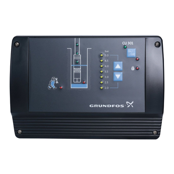
4. Control functions 4.2 Indication of pump operation On the graphical illustration on the CU 301 front, the 4.1 On/off button riser pipe shows running light when the pump is operating. Figure On/off button shows the on/off button of CU 301.
-
Page 14: Pressure Setting
4.3 Pressure setting 4.4 Button locking The two arrow buttons on the CU 301 front are used The buttons on CU 301 can be locked or unlocked by for the pressure setting. pressing the two arrow buttons simultaneously and holding them for 5 seconds or by using Grundfos GO Remote.
-
Page 15: Service Alarm
The possible alarms and how to identify them and make the relevant corrections are described in The pump performance Reduce the pump section 7.1 Fault finding with Grundfos GO Remote. is too high compared to performance using the borehole yield.
-
Page 16: Position Of Leds
Voltage alarm * • section 8. Technical data. • Permanent red light when communication between CU 301 and the No contact to pump * • pump is impossible. Press the on/off button to reset the alarm indication. Related information 6. Servicing the product 7.1 Fault finding with Grundfos GO Remote…
-
Page 17: Grundfos Go Remote Menu Overview
5.3.12 Indicator lights «Store settings» 5.3.13 Store settings «Recall settings» 5.3.14 Recall settings «Undo» 5.3.15 Undo «Unit configuration» 5.3.16 Unit configuration «Alarms and warnings» Section «Alarm log» 4.5 Alarm functions «Warning log» Related information 5.1 CU 301 with Grundfos GO Remote…
-
Page 18: Setting The Product
5.1 CU 301 with Grundfos GO Remote parameters. Grundfos GO Remote is used for wireless infrared communication with CU 301. During communication, 5.2.1 Controlled from there must be visual contact between CU 301 and This display shows the control source: Grundfos GO Remote. • CU 301 •…
-
Page 19: Settings
4-20 mA, 0-10 V, 2-10 V. • Setting range unit: bar or psi. Two CU 301 front covers are available, one for bar and another for psi. This means that a bar front cover can be replaced by a psi front cover.
-
Page 20
Setting range: 3000 — 10,700 min 5.3.7 Dry-running stop Factory setting 5.3.10 Buttons on product 10,700 min Disable the on/off button on CU 301 for protective reasons. Related information You can set the on/off button to the following: 5.3.1 Operating mode •… -
Page 21
Setting range: «Not active», 1, 2, ..199. Once a number setting is made, the factory setting (not active) is no longer available. If CU 301 and the pump do not have the same number, the alarm «No contact» will be indicated. Factory setting «Not active». -
Page 22: Servicing The Product
Related information To identify the cause of the service alarm, it is 4.8 Position of LEDs necessary to remove the front cover from CU 301. Fit the front cover as shown in fig. LEDs and alarm texts on the supply board to avoid disconnecting the multicore cable.
-
Page 23: Fault Finding The Product
If the pump has not started yet, proceed as follows: • Press the on/off button for 5 seconds. If the pump starts, CU 301 or the sensor may be defective. Note that the pressure is not controlled and may rise to a high level.
-
Page 24
12-14 inches or rewire using shielded cable. The CU 301 communication Are the three CU 301 supply board LEDs in pos. 2, 3 and 4 on part is defective. and is the control indicator LED flashing? See section 4.8 Position of… -
Page 25
Fault Possible cause Remedy CU 301 indicates The supply voltage is unstable Check — possibly over a period of time — that the supply voltage «Overvoltage» or or outside the voltage range is according to the values below. «Undervoltage». specified for the installed Voltage range for 200 — 240 V motors: motor type. -
Page 26
Disconnect the sensor in order to determine if it is defective. Replace defective sensor. • No: The load is OK, but the CU 301 sensor input may be defective. The pump is No communication. Check that the LED «No contact to pump» is on. -
Page 27: Technical Data
Voltage signal: Materials 0-10 VDC / 2-10 VDC, R = 11 kΩ. The CU 301 box is made of black PPO. Tolerance: ± 3 % at maximum voltage signal. EMC (electromagnetic compatibility) Screened cable is recommended. According to EN 60730-1.
-
Page 28
11 A 12 A 12 A Sensor alarm «No sensor used» (Grundfos GO Remote setting). See section 5.3.3 Analog input 200-240 V motors: Operation is guaranteed up to 280 VAC. 100-115 V motors: Operation is guaranteed up to 150 VAC. -
Page 29: Disposing Of The Product
1. Use the public or private waste collection service. 2. If this is not possible, contact the nearest Grundfos company or service workshop. The crossed-out wheelie bin symbol on a product means that it must be disposed of separately from household waste.
-
Page 30: Información General
Ajuste del producto … . . 45 Descripción del riesgo Unidad de control CU 301 con Grundfos Consecuencias de ignorar la advertencia GO Remote ….45 •…
-
Page 31: Instalación Del Producto
2. Instalación del producto Dimensiones PELIGRO Descarga eléctrica La unidad de control CU 301 se suministra con juntas Riesgo de muerte o lesión personal grave especiales para las entradas de cable Pg. Estas ‐ Antes de comenzar a trabajar con el juntas especiales son aptas para cables planos y producto, asegúrese de que el…
-
Page 32: Conexión Eléctrica
8. Datos técnicos. fuente de alimentación a los terminales 1 y 2. Cada terminal permite conectar cualquiera de los dos La unidad de control CU 301 tiene dos bloques de conductores. terminales: Conecte el conductor de tierra verde y amarillo el •…
-
Page 33: Ubicación Del Sensor De Presión
Si el sensor de presión se ubica más cerca del grifo de la ducha, la unidad de control CU 301 incrementará la presión cuando aumente el caudal. En ese caso, la presión en la ducha y en el grifo 2 se mantendrá…
-
Page 34: Ajuste De La Presión De Precarga
La comunicación de los datos se efectúa mediante una señal de alta frecuencia transmitida al cable de alimentación y conducida hasta los componentes electrónicos mediante bobinas de señal integradas en el motor y en la unidad de control CU 301, respectivamente.
-
Page 35
Pos. Descripción cables de alimentación de bombas conectados con Alimentación de los componentes unidades de control CU 301, tendidos en paralelo electrónicos mediante bandejas o conductos de cables y separados una distancia inferior a 25-30 cm, existe la Bobinas de señal posibilidad de que se produzca comunicación… -
Page 36
Con el fin de detener la bomba cuando no haya consumo de agua, la unidad de control CU 301 lleva a cabo la detección de caudal cada 10 segundos. La velocidad de la bomba se reducirá hasta que se registre una pequeña caída de presión, lo que… -
Page 37: Dimensionamiento Del Sistema
3.2 Dimensionamiento del sistema Para garantizar el correcto funcionamiento del sistema, es importante que la bomba sea del tipo adecuado. Durante el funcionamiento, la unidad de control CU 301 regula la velocidad de la bomba dentro de un rango comprendido entre 3.000 min y 10.700 min Consulte la fig.
-
Page 38: Uso Previsto
4-20 mA a la unidad de SQE 1-125 74 / 243 120 / 360 control CU 301. Dicha unidad de control ajusta el rendimiento de la bomba para mantener constante la SQE 1-140 81 / 266 136 / 405 presión;…
-
Page 39: Funciones De Control
4.2 Indicación de funcionamiento de la bomba En el esquema gráfico de la parte frontal de la unidad de control CU 301, aparecerán indicadores luminosos en la tubería vertical cuando la bomba esté funcionando. Cuando la bomba no esté funcionando, todos los indicadores luminosos estarán apagados.
-
Page 40: Ajuste De La Presión
4.4 Bloqueo de los botones Los dos botones de flecha situados en la parte frontal Los botones de la unidad de control CU 301 se de la unidad de control CU 301 se usan para ajustar pueden bloquear o desbloquear manteniendo la presión.
-
Page 41: Alarma De Servicio
El filtro del pozo está Lleve a cabo el obstruido. mantenimiento del pozo. Rearranque Una vez transcurridos 5 minutos (ajuste de fábrica) o el período configurado en Grundfos GO Remote, el motor volverá a arrancar automáticamente (consulte la sección 5.3.5 Rearranq. autom.).
-
Page 42: Ubicación De Los Indicadores Led
Información relacionada 5.3.7 Parada marcha en seco 8. Datos técnicos 4.8 Ubicación de los indicadores LED Pos. Indicación Descripción Indicador luminoso rojo que permanece encendido cuando existe una +24 V (sobrecarga) sobrecarga en el suministro interno de 24 V CC. Indicador luminoso verde que permanece encendido cuando el suministro +24 V interno de 24 V CC es correcto.
-
Page 43
Indicador luminoso rojo que permanece encendido cuando no se • Sin contacto con la puede establecer comunicación entre la unidad de control CU 301 y la bomba * bomba. Pulse el botón de encendido/apagado para restablecer la indicación de alarma. -
Page 44: Esquema De Los Menús De Grundfos Go Remote
5.3.13 Guardar ajustes “Recuperar config.” 5.3.14 Recuperar config. “Deshacer” 5.3.15 Anular “Conf. unidad” 5.2.9 Número de arranques “Alarma y aviso” Sección “Registro alarma” 4.5 Funciones de alarma “Registros de advertencia” Información relacionada 5.1 Unidad de control CU 301 con Grundfos GO Remote…
-
Page 45: Ajuste Del Producto
5. Ajuste del producto 5.2 Estado El menú “Estado” de Grundfos GO Remote para la unidad de control CU 301 ofrece la posibilidad de leer 5.1 Unidad de control CU 301 con Grundfos los parámetros de funcionamiento. GO Remote 5.2.1 Control. desde Grundfos GO Remote se usa para la comunicación…
-
Page 46: Ajustes
5.3 Ajustes Hay dos paneles frontales disponibles para la unidad de control CU 301: uno en bar y otro en psi. Es decir, El menú “Configuración” de Grundfos GO Remote el panel frontal en bar puede sustituirse por el panel para la unidad de control CU 301 ofrece la posibilidad frontal en psi y viceversa.
-
Page 47
Permite ajustar la velocidad máxima. Intervalo de ajuste: 3,000-10,700 min 5.3.10 Botones prod. Ajuste de fábrica Puede deshabilitar el botón de encendido/apagado de la unidad de control CU 301 por motivos de 10.700 min seguridad. Información relacionada Puede seleccionar los siguientes estados para el botón de encendido/apagado:… -
Page 48
Intervalo de ajuste: “Inactivo”, 1, 2,..199. Una vez configurado el número, el ajuste de fábrica (“Inactivo”) dejará de estar disponible. Si la unidad de control CU 301 y la bomba no tienen el mismo número, se activará la alarma “Sin contacto”. -
Page 49: Mantenimiento Y Revisión Del Producto
Para identificar la causa de la alarma de servicio, habrá que desmontar el panel frontal de la unidad de Información relacionada control CU 301. Monte el panel frontal como se 4.8 Ubicación de los indicadores LED muestra en la fig. Indicadores LED y descripciones de alarmas del panel de alimentación…
-
Page 50: Localización De Averías Del Producto
GO Remote PELIGRO La forma más sencilla de localizar averías en el Descarga eléctrica producto es mediante Grundfos GO Remote. Los Riesgo de muerte o lesión personal grave códigos de error pueden extraerse de la unidad y ‐ Antes de comenzar a trabajar con el leerse en el dispositivo.
-
Page 51
La conexión del cable • ¿Parpadea el indicador LED de control? se ilumina. multifilar es incorrecta o Si no es así, la unidad de control CU 301 presenta algún defectuosa. defecto. • Compruebe que la conexión del cable multifilar sea correcta. -
Page 52
No se está usando un motor Si la bomba ya había funcionado correctamente con una control CU 301 MSE 3. unidad de control CU 301 o CU 300, es de esperar que se tiene encendido el esté usando un motor MSE 3. indicador luminoso No existe ningún método para determinar el tipo de motor. -
Page 53
CU 301 es diferente. de control CU 301. CU 301 sigue Si la unidad de control CU 301 es nueva, es probable que su teniendo encendido número no coincida con el almacenado en la bomba SQE. Por el indicador lo tanto, el indicador luminoso “Sin contacto con la bomba”… -
Page 54
Compruebe si el indicador LED “Sin contacto con la bomba” y se detiene. está encendido. Si es así, eso significa que la unidad de control CU 301 arranca y para la bomba basándose únicamente en la señal del sensor. La unidad de control CU 301 debe restablecerse cada 250 paradas. -
Page 55: Datos Técnicos
95 %, máx. Entrada para sensores Materiales Señal de tensión: La caja de la unidad de control CU 301 está fabricada 0-10 V CC/2-10 V CC, R = 11 kΩ. en PPO negro. Tolerancia: ±3 % con la señal de tensión EMC (compatibilidad electromagnética)
-
Page 56
11 A 12 A 12 A Alarma de “No se usa sensor” (ajuste de Grundfos GO Remote); Consulte la sección 5.3.3 Entr. analóg. sensor Motores de 200-240 V: funcionamiento garantizado hasta 280 V CA. Motores de 100-115 V: funcionamiento garantizado hasta 150 V CA. -
Page 57: Eliminación Del Producto
1. Utilice un servicio público o privado de recogida de residuos. 2. Si ello no fuese posible, póngase en contacto con el distribuidor o taller de mantenimiento de Grundfos más cercano. El símbolo con el contenedor tachado que aparece en el producto significa que este no debe eliminarse junto con la basura doméstica.
-
Page 58: Généralités
Réglage du produit … . . 74 fonctionnement, dans les consignes de sécurité et les CU 301 avec Grundfos GO Remote ..74 instructions de maintenance Grundfos.
-
Page 59: Installation Du Produit
‐ Vérifier que la tension d’alimentation correspond aux valeurs indiquées sur la plaque signalétique. Le CU 301 est fourni avec des bagues spéciales pour ‐ L’utilisateur ou l’installateur est l’entrée des câbles Pg. Les bagues spéciales sont responsable de la conformité de la adaptées aux câbles plats et aux câbles unipolaires.
-
Page 60: Branchement Électrique
Serrer les bornes 5 à 7. Brancher le fil de mise à la terre vert et jaune à la De plus, le CU 301 est muni de deux bornes à visser borne PE. Chaque borne PE ne doit être connectée pour les câbles de mise à…
-
Page 61: Positionnement Du Capteur De Pression
Si le capteur de pression est placé plus près du robinet de la douche, le CU 301 augmentera la pression à mesure que le débit augmente. La pression restera alors constante au robinet 2 et à la douche, mais la pression au robinet 1 augmentera.
-
Page 62: Réglages De La Pression De Précharge
La pression est mesurée à l’aide d’un capteur de Pour assurer la protection contre une éventuelle pression, qui transmet un signal au CU 301. Le CU surpression, installer une soupape de décharge de 301 adapte les performances de la pompe en pression en aval de la tête du forage.
-
Page 63
Alimentation électrique d’alimentation (communication par courants porteurs Signaux de communication en ligne) montre le principe de communication par courants porteurs en ligne entre le CU 301 et la Grundfos GO Remote pompe. Lors du démarrage de la pompe CU 301 La pompe démarre pour l’une des raisons suivantes :… -
Page 64
0,5 bar au-dessus de la pression préréglée. Détection du débit Lors du fonctionnement de la pompe (lorsque de l’eau est consommée), le CU 301 ajuste la vitesse de la pompe pour maintenir une pression constante. Pour arrêter la pompe lorsque de l’eau n’est pas consommée, le CU 301 détecte le débit toutes les 10… -
Page 65: Dimensions De L’installation
3.2 Dimensions de l’installation Pour garantir le bon fonctionnement de l’installation, il faut veiller à ce que la pompe soit du type approprié. Lors du fonctionnement, le CU 301 contrôle la vitesse de la pompe de 3000 min à 10.700 min .
-
Page 66
La hauteur manométrique max. au débit max. ainsi Informations connexes que la hauteur manométrique min. sans débit sont 7.1 Dépannage avec Grundfos GO Remote reprises dans le tableau suivant : Hauteur mano- Hauteur mano- métrique min. à métrique max. à Type de… -
Page 67: Usage Prévu
La pression est mesurée à l’aide d’un capteur de pression, qui transmet un signal 4-20 mA au CU 301. Le CU 301 adapte les performances de la pompe en conséquence, pour maintenir une pression constante en modifiant la vitesse de pompage.
-
Page 68: Fonctions De Régulation
4. Fonctions de régulation 4.2 Indication du fonctionnement de la pompe 4.1 Bouton marche/arrêt Sur l’illustration à l’avant du CU 301, la colonne montante affiche un voyant fixe lorsque la pompe La figure Bouton marche/arrêt présente le bouton fonctionne. marche / arrêt du CU 301.
-
Page 69: Réglage De La Pression
4.3 Réglage de la pression 4.4 Verrouillage des boutons Les deux boutons fléchés sur l’avant du CU 301 sont Les boutons du CU 301 peuvent être verrouillées ou utilisés pour le réglage de la pression. déverrouillées en appuyant simultanément sur les deux boutons fléchés pendant 5 secondes ou en…
-
Page 70: Alarme De Maintenance
La maintenance du fora- bloqué. ge est nécessaire. 7.1 Dépannage avec Grundfos GO Remote Redémarrage Après 5 minutes (réglage d’usine) ou la période définie dans Grundfos GO Remote (voir paragraphe 5.3.5 Redémarrage automatique), le moteur redémarre automatiquement. Informations connexes 5.3.7 Arrêt marche à sec…
-
Page 71: Position Des Led
4.8 Position des LED Pos. Indication Description Voyant lumineux rouge fixe lorsque l’alimentation 24 VDC interne est sur- surcharge +24 V chargée. Voyant lumineux vert fixe lorsque l’alimentation 24 VCC interne est norma- +24 V Voyant lumineux vert fixe lorsque l’alimentation 10 VCC interne est norma- +10 V Voyant lumineux vert fixe lorsque l’alimentation 5 VCC interne est norma- +5 V…
-
Page 72
8. Caractéristiques techni- • ques. • Aucun contact avec la • Voyant lumineux rouge fixe lorsque la communication entre le CU 301 pompe * et la pompe est impossible. Appuyer sur le bouton marche/arrêt pour réinitialiser l’alarme. Informations connexes 6. Maintenance 7.1 Dépannage avec Grundfos GO Remote… -
Page 73: Présentation Du Menu Grundfos Go Remote
4.9 Présentation du menu Grundfos GO Remote «État» Paragraphe «Régulation depuis» 5.2.1 Régulation depuis »Valeur, capteur 1″ 5.2.2 Valeur, capteur 1 «Température du moteur» 5.2.3 Température moteur «Vitesse du moteur» 5.2.5 Vitesse du moteur »Consommation électrique» 5.2.6 Consommation électrique »Consommation énergétique» 5.2.7 Consommation énergétique…
-
Page 74: Réglage Du Produit
(tr/min). 301. Lorsque la communication entre Grundfos GO 5.2.6 Consommation électrique Remote et le CU 301 a été établie, le voyant Cet affichage montre la consommation électrique lumineux rouge (A) du bouton marche/arrêt clignote. réelle. Pour plus d’informations sur l’utilisation de Grundfos Informations connexes GO Remote, se référer aux instructions de…
-
Page 75: Réglages
5.3 Réglages • Unité de plage de réglage : bar ou psi. Deux façades sont disponibles pour le CU 301, une Le menu «Paramètres» de Grundfos GO Remote pour en bar et une en psi. La façade en bar peut être le CU 301 permet de modifier les paramètres de…
-
Page 76
Plage de réglage : 3 000 — 10 700 min 5.3.7 Arrêt marche à sec Réglage par défaut 5.3.10 Touches sur le produit 10 700 min Désactiver le bouton marche/arrêt du CU 301 pour Informations connexes une question de sécurité. Vous pouvez régler le bouton marche/arrêt comme 5.3.1 Mode de fonctionnement suit : •… -
Page 77
Plage de réglage : «Inactif», 1, 2,..199. Une fois le chiffre paramétré, le réglage par défaut (inactif) n’est plus disponible. Si le CU 301 et la pompe n’ont pas le même chiffre, l’alarme «Aucun contact» s’activera. Réglage par défaut «Inactif». -
Page 78: Maintenance
• Aucun contact avec la pompe Informations connexes Pour identifier la cause de l’alarme d’entretien, vous devez retirer la façade du CU 301. Installer la façade 4.8 Position des LED comme illustré dans la fig. LED et textes d’alarme sur le panneau d’alimentation pour éviter de débrancher…
-
Page 79: Dépannage
7. Dépannage 7.1 Dépannage avec Grundfos GO Remote La manière la plus simple de détecter les pannes est DANGER d’utiliser Grundfos GO Remote. Les codes d’erreur Choc électrique peuvent être extraits de l’unité et affichées sur Mort ou blessures graves l’appareil.
-
Page 80
Si la pompe n’a pas encore démarré, procéder comme suit : • Appuyer sur le bouton marche/arrêt pendant 5 secondes. Si la pompe démarre, le CU 301 ou le capteur peut être défectueux. Noter que la pression n’est pas contrôlée et peut atteindre un niveau élevé. -
Page 81
Oui : L’alimentation électrique est fonctionnelle. Attribuer un nouveau chiffre au système. Si cela ne fonctionne pas, le CU 301 ou le module de commu- nication du moteur est défectueux. Remplacer le CU 301 et attribuer un nouveau chiffre au systè- me, entre 1 et 64, afin d’établir une correspondance entre la… -
Page 82
Défaut Cause possible Solution Le CU 301 indique La tension d’alimentation est Vérifier (si possible pendant une certaine période) que la ten- «Surtension» ou instable ou n’entre pas dans la sion d’alimentation correspond aux valeurs ci-dessous. «Sous-tension». plage de tension spécifiée… -
Page 83
Vérifier que la LED «Aucun contact avec la pompe» est allu- ne par intermitten- mée. Si c’est le cas, le CU 301 démarre et arrête la pompe en fonc- tion du signal du capteur. Le CU 301 doit être réinitialisé tous les 250 arrêts. -
Page 84: Caractéristiques Techniques
1,35 kg. Humidité relative Maximum 95 %. Matériaux Entrée capteur Le boîtier du CU 301 est conçu en PPO noir. Signal de tension : CEM (compatibilité électromagnétique) 0-10 VCC / 2-10 VCC, R = 11 kΩ. Conformément à la norme EN 60730-1.
-
Page 85
8,4 A 11 A 12 A 12 A Alarme de «Aucun capteur utilisé» (paramètre Grundfos GO Remote). Voir paragraphe 5.3.3 Entrée analo- capteur gique Moteurs 200-240 V : Le fonctionnement est garanti jusqu’à 280 V CA. Moteurs 100-115 V : Le fonctionnement est garanti jusqu’à 150 V CA. -
Page 86: Mise Au Rebut
1. Utiliser le service de collecte des déchets public ou privé. 2. Si ce n’est pas possible, contacter Grundfos ou le réparateur agréé le plus proche. Le pictogramme représentant une poubelle à roulettes bar- rée apposé…
-
Page 87
Argentina China Greece Bombas GRUNDFOS de Argentina S.A. GRUNDFOS Pumps (Shanghai) Co. Ltd. GRUNDFOS Hellas A.E.B.E. Ruta Panamericana km. 37.500industin 10F The Hub, No. 33 Suhong Road 20th km. Athinon-Markopoulou Av. 1619 — Garín Pcia. de B.A. Minhang District P.O. Box 71 Tel.: +54-3327 414 444… -
Page 88
Fax: +66-2-725 8998 Fax: + 370 52 395 431 Москва, RU-109544, Russia Turkey Тел. (+7) 495 564-88-00 (495) 737-30-00 Malaysia GRUNDFOS POMPA San. ve Tic. Ltd. Факс (+7) 495 564 8811 GRUNDFOS Pumps Sdn. Bhd. Sti. E-mail grundfos.moscow@grundfos.com 7 Jalan Peguam U1/25 Gebze Organize Sanayi Bölgesi… -
Page 89
99406808 12.2022 ECM: 1352106 www.grundfos.com…
- Manuals
- Brands
- Grundfos Manuals
- Control Unit
- CU 301
- Installation and operating instructions manual
-
Contents
-
Table of Contents
-
Troubleshooting
-
Bookmarks
Quick Links
GRUNDFOS INSTRUCTIONS
CU 301
Installation and operating instructions
Related Manuals for Grundfos CU 301
Summary of Contents for Grundfos CU 301
-
Page 1
GRUNDFOS INSTRUCTIONS CU 301 Installation and operating instructions… -
Page 2: Limited Warranty
Products which are sold but not manufactured by Grundfos are subject to the warranty provided by the manu- facturer of said products and not by Grundfos’ warranty. Grundfos will not be liable for damage or wear to products caused by abnormal operating conditions, accident, abuse, misuse, unauthorized alteration or repair, or if the product was not installed in accordance with Grundfos’ printed installation and operating instructions.
-
Page 3
CU 301 Installation and operating instructions… -
Page 4: Table Of Contents
5.3.1 Sensor 5.3.2 Choice of sensor 5.3.3 Maximum pressure setting 5.3.4 Automatic restart 5.3.5 Dry-running stop 5.3.6 Maximum speed 5.3.7 Cut-in speed 5.3.8 Buttons on the CU 301 5.3.9 Indication of pump operation 5.3.10 Number Print Troubleshooting Service Technical data Electrical connection 8.1.1 Mains supply…
-
Page 5: Constant-Pressure Control
1. Constant-pressure control CU 301 The control unit CU 301 is for use only with Grundfos CU 301 SQE pumps incorporating electronic power factor correction (PFC). 1.1 Description The system maintains a constant pressure within the maximum pump performance in spite of a varying water consumption.
-
Page 6
Flow detection The pump starts as a consequence of During pump operation, i.e. when water is con- sumed, the CU 301 will adjust the pump speed to • a high flow or maintain a constant pressure. In order to stop the •… -
Page 7: System Sizing
22 SQE-80 system pressure. 22 SQE-120 Comment: If this is not fulfilled, the pressure may fall below the pressure set on the CU 301. 22 SQE-160 Maximum head at rated flow and minimum head at 22 SQE-190 no flow can be found in the following sections.
-
Page 8: Positioning The Pressure Sensor
1.6 Precharge pressure setting The CU 301 is designed to work with a 2 gal. dia- phragm tank. The precharge pressure of the diaphragm tank must be set to 70% of the pressure setting in order to use the tank to the limit of its capacity.
-
Page 9: Operating Functions
2.3 Pressure setting flashing ing with the R100. The two arrow buttons on the CU 301 front are used for the pressure setting, see fig. 10. * If the On/Off button has been used to stop the pump, this button must also be used for restarting.
-
Page 10: Button Locking
The alarm functions indicated on the Setting range: 40-100 psi. CU 301 front are described in the following sections. Arrow-up button 3.1 Service alarm When this button is pressed, the system pressure If one or more factory-set alarm values are setting is increased in steps of 10 psi.
-
Page 11: Dry-Running Protection
5 seconds, and the motor speed is within 1,000 rpm of the maximum speed setting as defined in the section 5.3.6, the CU 301 stops the pump and declares a dry-running alarm. When the motor is stopped, the dry-running indicator light is permanently on, see fig.
-
Page 12: Position Of Leds
Permanent red light when the supply voltage is out of range, see section Voltage alarm *) 8. Technical data. Permanent red light when communication between the CU 301 and the No contact to pump *) pump is impossible. *) Press the On/Off button to reset the alarm indication.
-
Page 13: Cu 301 With R100
The R100 communicates via infrared light. During communication, there must be visual contact between the CU 301 and the R100. The best visual contact between the two units is obtained by pointing the R100 at the lower arrow button or by removing the front cover and pointing the R100 at the right side of the CU 301, see fig.
-
Page 14: Menu Overview
0. GENERAL 1. OPERATION 2. STATUS 3. INSTALLATION 5.3.1 5.2.1 5.1.1 5.1.2 5.2.2 5.3.2 5.2.3 5.1.3 5.3.3 5.1.3 5.2.4 5.3.4 5.3.5 5.2.5 5.2.6 5.3.6 5.3.7 5.3.8 5.3.9 5.3.10 Fig. 16 Menu overview…
-
Page 15: Menu Operation
5.1 Menu OPERATION 5.1.3 Alarm The OPERATION menu for the CU 301 offers the possibility of setting and reading operating parame- ters. Factory settings are marked in bold-faced type under each individual display. 5.1.1 Pressure setting This display shows the current alarm status.
-
Page 16: Menu Status
5.2 Menu STATUS 5.2.3 Speed The STATUS menu for the CU 301 provides operat- ing data about pump/motor and sensor. It is not pos- sible to change or set values in this menu. When [OK] is pressed continuously in this display, the displayed value is being updated.
-
Page 17: Operating Hours And Number Of Starts
• Sensor output signal: «–» (not active), 0-20 mA, The setting of this display overrules the possibility of using the arrow button on the CU 301 front to 4-20 mA, 0-10 V, 2-10 V. increase the pressure to a setting above the •…
-
Page 18: Automatic Restart
5.3.4 Automatic restart Relation to other displays The actual pump power input can be read in display 5.2.5 Power input and power consumption. If the maximum pump speed has been reduced in display 5.3.6 Maximum speed, the dry-running stop value must be changed. 5.3.6 Maximum speed Set the automatic restart time from stop, caused by an alarm, to restart attempt.
-
Page 19: Buttons On The Cu 301
• Running light • Constant light. 5.3.10 Number Allocate a number to the CU 301 and the pump con- nected. The CU 301 and the pump must have the same number. The CU 301 control unit communicates with the SQE…
-
Page 20: Print
6. Print The actual data in the R100 can be printed on a Hewlett-Packard printer type HP82240B. Navigate the R100 to the print menu and point the R100 at the IR sensor of the printer and press [OK]. The following information will be printed:…
-
Page 21: Troubleshooting
• No contact to pump. To identify the cause of the service alarm, it is necessary to remove the front cover from the CU 301 or use the R100. Fit the front cover as shown in fig. 18 to avoid disconnecting the multi-core cable.
-
Page 22
If the pump has not started yet, proceed as follows: • Press the On/Off button for 5 seconds. If the pump starts, the CU 301 or the sensor may be defective. Note: The pressure is not controlled and may rise to a high level. -
Page 23
If the pump has already worked satisfactorily with a cates «No contact to MSE 3. CU 301 or a CU 300, the motor can be expected to be pump». an MSE 3. There is no technical way of determining the motor type. -
Page 24
7. The CU 301 indi- a) The supply voltage is Check — possibly over a period of time — that the supply cates «Overvoltage» unstable or outside voltage is according to the values below. or «Undervoltage». the voltage range • Motor type 0.5 hp = 198-315 V specified for the in- •… -
Page 25: Technical Data
100 mA. Disconnect the sensor in order to determine if it is de- fective. Replace defective sensor. No: The load is OK, but the CU 301 sensor input may be defective. 14. The pump is operat- a) No communication. Check that the LED «No contact to pump» is on.
-
Page 26: Electrical Connection
SQE-NE SQE-NE SQE-NE All models 0.5 hp 0.75 hp 1.0 hp 1.5 hp Sensor defective 4-20 mA (the value is stored in the CU 301) Overload 5.2 A 8.4 A 11.2 A 12 A 11 A Stop limit: Stop limit:…
-
Page 27: Mains Supply
POWER PUMP Fig. 20 Electrical connection of the CU 301 In situations where multiple CU 301 pump power Legend cables are run parallel in wiring trays or conduit and less than 10-12 inches apart, the possibility for Pos. Description undesired communication between units exists.
-
Page 28: Pressure Sensor Voltage Chart
9. Pressure sensor voltage chart Voltage to pressure chart for CU 301 pressure sensors. Measure the DC voltage between «SENSOR IN» and «SENSOR GND». Voltages lower than 2 or higher than 10 indicate an incorrectly wired or a faulty sensor.
-
Page 29: Disposal
This product or parts of it must be disposed of in an environmentally sound way: 1. Use the public or private waste collection service. 2. If this is not possible, contact the nearest Grundfos company or service workshop. Subject to alterations.
-
Page 30
U.S.A. Canada Mexico GRUNDFOS Pumps Corporation GRUNDFOS Canada Inc. Bombas GRUNDFOS de Mexico 17100 West 118th Terrace 2941 Brighton Road S.A. de C.V. Olathe, Kansas 66061 Oakville, Ontario Boulevard TLC No. 15 Phone: +1-913-227-3400 L6H 6C9 Parque Industrial Stiva Telefax: +1-913-227-3500… -
Page 31
Being responsible is our foundation Thinking ahead makes it possible Innovation is the essence 5/06 L-SP-TL-019 www.grundfos.com…
Скважинные насосы Grundfos SQE, пожалуй, знакомы многим своей надежностью и эффективностью. Но если их дополняет блок управления CU 301, они становятся еще более привлекательными. Итак, что же такое CU 301 и что он может? Рассказываем.
Содержание
- Что может блок управления CU 301
- Блок управления CU 301: принцип действия и подготовка к работе
- Регистрация и диагностика неисправностей
- Пульт дистанционного управления R100
Блок управления CU 301 разработан специально для того, чтобы использовать его со скважинными насосами Grundfos SQE.
Применение устройства дает возможность, в частности:
- стабилизировать давление воды, даже если изменяется водоотбор;
- задавать величину давления воды;
- отслеживать главные показатели работы оборудования и отображать их на панели.
Насосы Grundfos SQE комплектуются, как правило, электромоторами MSE 3. В них заложена способность изменять обороты в границах от 65 до 100 % своих технических возможностей. В результате это позволяет выбирать в этих пределах показатели расхода и давления в любой точке отбора.
Блок управления CU 301 дает возможность так варьировать обороты двигателя насоса, чтобы водяное давление в сети не менялось даже при непостоянном водопотреблении.
С подключением и подготовкой к работе блока управления CU 301, в принципе, легко справится и непрофессиональный пользователь. Потому что производитель позаботился об идеальном совмещении устройств без дополнительной настройки и лишних органов управления. Поэтому работа системы будет простой и стабильной.
Блок управления CU 301 может входить в состав комплекта насоса Grundfos SQE. Распаковку такого насоса можно увидеть на следующем видео:
Блок управления CU 301: принцип действия и подготовка к работе
Блок управления CU 301 не нуждается в отдельном кабеле для связи с насосом: она реализована через обычный сетевой шнур.
Чтобы блок в связке с насосом работали нормально, нужно подсоединить внешний датчик давления и гидроаккумулятор хотя бы небольшой емкости. Устанавливать блок управления надо в сухом месте. И, как правило, неподалеку от смонтированного на трубопроводе гидроаккумулятора и датчика. Блок с датчиком рекомендуется разместить в непосредственной близости друг к другу либо использовать для соединения экранированный кабель.
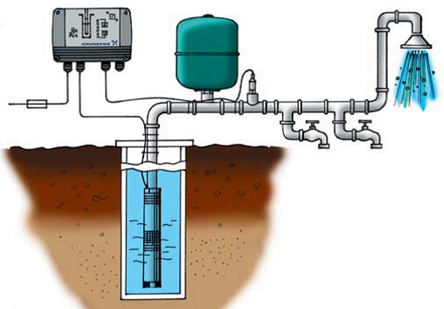
Датчик снимает показатели и отсылает их управляющему устройству. Контроллер сопоставляет их с введенной пользователем величиной. И плавно регулирует обороты электродвигателя. В результате удается:
- поддерживать стабильное давление воды;
- по желанию пользователя легко регулировать давление в границах развиваемой насосом мощности;
- снижать расход электроэнергии за счет небольших оборотов двигателя при малом водоразборе.
Блок управления включает насос, если возникают следующие ситуации:
- Во-первых, если давление воды в системе снижается быстрее, чем на 0,1 бар/с. Чем больше вместимость гидроаккумулятора, тем медленнее падает давление. Так, при установке емкости на 8 л давление упадет на 0,1 бар/с при расходе воды от 0,18 м³/ч. Если объем бака будет больше, давление при том же расходе снизится слабее.
- Во-вторых, если давление в сети стало на 0,5 бар меньше заданного. Блок управления регулирует интенсивность работы насоса, поддерживая заданное давление в интервалах ±0,2 бар. Но если расход изменяется резко и скачкообразно, показатель давления может кратковременно колебаться в больших пределах. Это нормально и не является неисправностью.
Когда отбор воды прекращается, блок управления плавно уменьшает обороты двигателя насоса. В то же время контролируя давление в системе. Если давление превысило заданное на 0,5 бар, и снижения его не происходит, устройство отключает насос.
Пределы регулировки блока CU 301 по давлению: в интервале 2 – 5 бар (с шагом 0,5 бар);
Пределы регулировки блока CU 301 по оборотам двигателя: в интервале 7000 – 10700 об/мин.
Читайте также: Какой скважинный насос выбрать
Регистрация и диагностика неисправностей
Блок реагирует, в частности, на такие ошибки и сбои в работе системы:
- отсутствие питания в сети;
- повышенное напряжение;
- перегрев;
- перегрузку;
- выход из строя датчика давления;
- прекращение связи с насосом;
- сухой ход;
- снижение производительности насоса.
Непосредственно на панель управления выводится только сигнал о работе всухую. Другие ошибки вызывают включение индикатора «Сервис». Уточнить, по какой именно причине он сработал, можно по горящему светодиодному указателю на плате питания. Возможные варианты приведены в руководстве по эксплуатации. Доступ к плате питания открывается при снятой панели управления. Как бы то ни было, блок управления в автоматическом режиме включит насос спустя 5 минут после сбоя в работе. Время перезапуска можно задать при помощи пульта дистанционного управления R100.
Читайте также: Тонкости установки скважинного насоса Grundfos
Пульт дистанционного управления R100
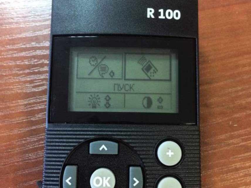
Подключение пульта дистанционного управления предоставляет блоку новые расширенные функции. Например, есть возможность изменить показатели напряжения, силы тока и параметров сигнала от датчика давления. Более того, можно узнать потребление энергии, частоту оборотов двигателя, срок его работы и количество запусков. А также задать параметры включения защиты от сухого хода, и т.д. Но блок управления может работать и без пульта.
Нажмите, пожалуйста, на одну из кнопок, чтобы узнать понравилась статья или нет.

Чтобы ознакомиться с инструкцией выберите файл в списке, который вы хотите скачать, нажмите на кнопку «Скачать» и вы перейдете на страницу, где необходимо будет ввести код с картинки. При правильном ответе на месте картинки появится кнопка для получения файла.
Если в поле с файлом есть кнопка «Просмотр», это значит, что можно просмотреть инструкцию онлайн, без необходимости скачивать ее на компьютер.
В случае если материал по вашему не полный или нужна дополнительная информация по этому устройству, например драйвер, дополнительные файлы например, прошивка или микропрограмма, то вы можете задать вопрос модераторм и участникам нашего сообщества, которые постараются оперативно отреагировать на ваш вопрос.
Также вы можете просмотривать инструкции на своем устройстве Android
Источник
CU 301 – эффективный блок управления для насосов Grundfos SQE
Скважинные насосы Grundfos SQE, пожалуй, знакомы многим своей надежностью и эффективностью. Но если их дополняет блок управления CU 301, они становятся еще более привлекательными. Итак, что же такое CU 301 и что он может? Рассказываем.
Что может блок управления CU 301
Блок управления CU 301 разработан специально для того, чтобы использовать его со скважинными насосами Grundfos SQE.
Применение устройства дает возможность, в частности:
- стабилизировать давление воды, даже если изменяется водоотбор;
- задавать величину давления воды;
- отслеживать главные показатели работы оборудования и отображать их на панели.
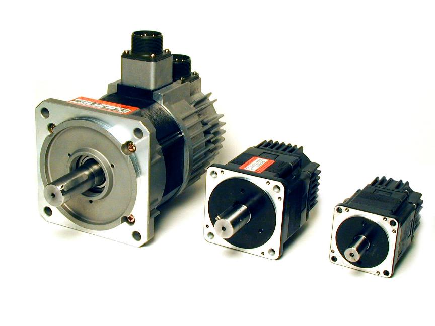
Насосы Grundfos SQE комплектуются, как правило, электромоторами MSE 3. В них заложена способность изменять обороты в границах от 65 до 100 % своих технических возможностей. В результате это позволяет выбирать в этих пределах показатели расхода и давления в любой точке отбора.
Электромоторы марки MSE
Блок управления CU 301 дает возможность так варьировать обороты двигателя насоса, чтобы водяное давление в сети не менялось даже при непостоянном водопотреблении.
С подключением и подготовкой к работе блока управления CU 301, в принципе, легко справится и непрофессиональный пользователь. Потому что производитель позаботился об идеальном совмещении устройств без дополнительной настройки и лишних органов управления. Поэтому работа системы будет простой и стабильной.
Блок управления CU 301 может входить в состав комплекта насоса Grundfos SQE. Распаковку такого насоса можно увидеть на следующем видео:
Блок управления CU 301: принцип действия и подготовка к работе
Блок управления CU 301 не нуждается в отдельном кабеле для связи с насосом: она реализована через обычный сетевой шнур.
Чтобы блок в связке с насосом работали нормально, нужно подсоединить внешний датчик давления и гидроаккумулятор хотя бы небольшой емкости. Устанавливать блок управления надо в сухом месте. И, как правило, неподалеку от смонтированного на трубопроводе гидроаккумулятора и датчика. Блок с датчиком рекомендуется разместить в непосредственной близости друг к другу либо использовать для соединения экранированный кабель.
Датчик снимает показатели и отсылает их управляющему устройству. Контроллер сопоставляет их с введенной пользователем величиной. И плавно регулирует обороты электродвигателя. В результате удается:
- поддерживать стабильное давление воды;
- по желанию пользователя легко регулировать давление в границах развиваемой насосом мощности;
- снижать расход электроэнергии за счет небольших оборотов двигателя при малом водоразборе.
Блок управления включает насос, если возникают следующие ситуации:
- Во-первых, если давление воды в системе снижается быстрее, чем на 0,1 бар/с. Чем больше вместимость гидроаккумулятора, тем медленнее падает давление. Так, при установке емкости на 8 л давление упадет на 0,1 бар/с при расходе воды от 0,18 м³/ч. Если объем бака будет больше, давление при том же расходе снизится слабее.
- Во-вторых, если давление в сети стало на 0,5 бар меньше заданного. Блок управления регулирует интенсивность работы насоса, поддерживая заданное давление в интервалах ±0,2 бар. Но если расход изменяется резко и скачкообразно, показатель давления может кратковременно колебаться в больших пределах. Это нормально и не является неисправностью.
Когда отбор воды прекращается, блок управления плавно уменьшает обороты двигателя насоса. В то же время контролируя давление в системе. Если давление превысило заданное на 0,5 бар, и снижения его не происходит, устройство отключает насос.
Пределы регулировки блока CU 301 по давлению: в интервале 2 – 5 бар (с шагом 0,5 бар);
Пределы регулировки блока CU 301 по оборотам двигателя: в интервале 7000 – 10700 об/мин.
Регистрация и диагностика неисправностей
Блок реагирует, в частности, на такие ошибки и сбои в работе системы:
- отсутствие питания в сети;
- повышенное напряжение;
- перегрев;
- перегрузку;
- выход из строя датчика давления;
- прекращение связи с насосом;
- сухой ход;
- снижение производительности насоса.
Непосредственно на панель управления выводится только сигнал о работе всухую. Другие ошибки вызывают включение индикатора «Сервис». Уточнить, по какой именно причине он сработал, можно по горящему светодиодному указателю на плате питания. Возможные варианты приведены в руководстве по эксплуатации. Доступ к плате питания открывается при снятой панели управления. Как бы то ни было, блок управления в автоматическом режиме включит насос спустя 5 минут после сбоя в работе. Время перезапуска можно задать при помощи пульта дистанционного управления R100.
Пульт дистанционного управления R100
Подключение пульта дистанционного управления предоставляет блоку новые расширенные функции. Например, есть возможность изменить показатели напряжения, силы тока и параметров сигнала от датчика давления. Более того, можно узнать потребление энергии, частоту оборотов двигателя, срок его работы и количество запусков. А также задать параметры включения защиты от сухого хода, и т.д. Но блок управления может работать и без пульта.
Источник
Блок управления Grundfos CU 301
Блок управления Grundfos CU 301
Устройство управления насосами SQE
— Блок управления Grundfos CU 301, контроля и регулирования для насосов SQE, работающих при постоянном давлении.
Система поддерживает постоянное давление при обеспечении максимальных характеристик насоса независимо от изменяющегося расхода воды.
Давление регистрируется датчиком давления, и его значение передается на CU 301. Блок управления CU 301 производит корректировку рабочих параметров насоса, если это необходимо.
Блок управления CU 301
CU 301 представляет собой блок управления, контроля и регулирования, специально разработанный для насосов SQE, работающих при постоянном давлении.
Блок управления CU 301 имеет следующие функции:
- Полное управление насосами SQE.
- Двусторонняя связь с насосами SQE.
- Возможность регулировки давления.
- Плавный останов.
- Аварийная индикация, при возникновении неисправности во время эксплуатации.
- Включение, выключение или сброс установочных параметров насоса с помощью кнопки.
- Дистанционное управление с помощью устройства беспроводной связи Grundfos GO.
CU 301 осуществляет обмен данными с насосом через сетевой кабель, поэтому нет необходимости в дополнительном кабеле
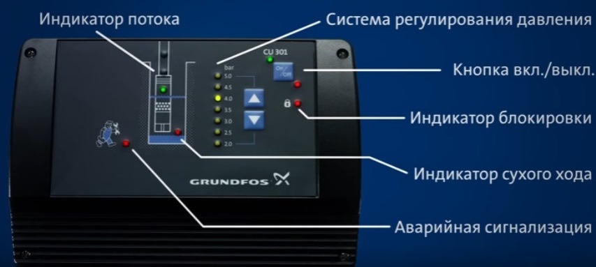
CU 301 оборудован):
1. Индикатором потока
2. Системой регулирования давления
3. Кнопкой вкл. /выкл.
4. Индикатором блокировки
5. Индикатором сухого хода
6. Аварийной сигнализацией в следующих случаях:
– Нет связи с насосом
– Перенапряжение
– Падение напряжения
– Снижение числа оборотов
– Перегрев
– Перегрузка
– Неисправность датчика
Гарантия: 12 мес.
Предлагаем Вам купить Блок управления Grundfos CU 301 по выгодной цене 25 418 р.
Блок управления Grundfos CU 301 отличается высоким качеством и оптимальной ценой. Производитель известен во всем мире и предоставляет гарантию на свою продукцию.
Чтобы купить Блок управления Grundfos CU 301 в нашем интернет магазине вам достаточно оформить заказ онлайн на сайте
Источник
Блок управления скважинным насосом Grundfos CU-301
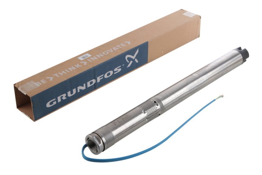
Блок управления Grundfos CU-301 представляет собой блок управления, контроля и регулирования, специально разработанный для скважинных насосов Grundfos SQE, работающих при постоянном давлении.
Блок управления CU-301 имеет следующие функции:
— Полное управление насосами SQE
— Двусторонняя связь с насосами SQE
— Возможность регулировки давления
— Аварийная индикация при возникновении неисправности в работе насоса
— Дистанционное управление с помощью пульта R100
— Включение, выключение или сброс установочных параметров насоса с помощью кнопки
CU-301 осуществляет связь с насосом через сетевой кабель (проводная ВЧ-связь), поэтому нет необходимости в дополнительном кабеле.
Блок управления CU-301 оборудован:
1. Индикатором потока
2. Системой регулирования давления
3. Кнопкой вкл./выкл.
4. Индикатором блокировки
5. Индикатором сухого хода
6. Аварийной сигнализацией в следующих случаях:
— Нет связи
— Перенапряжение
— Падение напряжения
— Снижение числа оборотов
— Перегрев
— Перегрузка
— Неисправность датчика
Блок CU-301 имеет аналоговый вход от датчика давления.
Кроме того, блок CU-301 дает возможность дистанционного управления.
Дистанционное управление R100
Инфракрасное беспроводное дистанционное управление блока CU 301 можно осуществить с помощью R100.
Источник
Блок управления Grundfos CU 301 / CU 301 Control Unit — 96436753
- Модель: CU 301
- Производитель: Grundfos
- Артикул: 96436753
- Гарантия: 2 года
- Наличие: Есть в наличии
Резерв товара
Блок управления, контроля и регулирования Grundfos CU 301 представляет собой устройство для управления насосами SQE, работающими при постоянном давлении. Постоянное давление поддерживается системой управления при обеспечении максимальных характеристик насоса вне зависимости от расхода воды, который может изменяться. Давление регистрирует специальный датчик, это значение выводится на CU 301. Блок управления CU 301 корректирует рабочие параметры насоса, если это необходимо.
Обнаружив ошибку или неточность в тексте или описании товара, выделите ее и нажмите Shift+Enter.
| Блок управления Grundfos CU 301 / CU 301 Control Unit — 96436753 — 1 шт. |
| Инструкция по эксплуатации — 1 шт. |
| Поставляется в коробке |
Обнаружив ошибку или неточность в тексте или описании товара, выделите ее и нажмите Shift+Enter.
Обнаружив ошибку или неточность в тексте или описании товара, выделите ее и нажмите Shift+Enter.
Обнаружив ошибку или неточность в тексте или описании товара, выделите ее и нажмите Shift+Enter.
Источник
Adblock
detector
Устройство управления насосами SQE
— Блок управления Grundfos CU 301, контроля и регулирования для насосов SQE, работающих при постоянном давлении.
Система поддерживает постоянное давление при обеспечении максимальных характеристик насоса независимо от изменяющегося расхода воды.
Давление регистрируется датчиком давления, и его значение передается на CU 301. Блок управления CU 301 производит корректировку рабочих параметров насоса, если это необходимо.
Блок управления CU 301
CU 301 представляет собой блок управления, контроля и регулирования, специально разработанный для насосов SQE, работающих при постоянном давлении.
Блок управления CU 301 имеет следующие функции:
- Полное управление насосами SQE.
- Двусторонняя связь с насосами SQE.
- Возможность регулировки давления.
- Плавный останов.
- Аварийная индикация, при возникновении неисправности во время эксплуатации.
- Включение, выключение или сброс установочных параметров насоса с помощью кнопки.
- Дистанционное управление с помощью устройства беспроводной связи Grundfos GO.
CU 301 осуществляет обмен данными с насосом через сетевой кабель, поэтому нет необходимости в дополнительном кабеле
CU 301 оборудован):
1. Индикатором потока
2. Системой регулирования давления
3. Кнопкой вкл. /выкл.
4. Индикатором блокировки
5. Индикатором сухого хода
6. Аварийной сигнализацией в следующих случаях:
– Нет связи с насосом
– Перенапряжение
– Падение напряжения
– Снижение числа оборотов
– Перегрев
– Перегрузка
– Неисправность датчика
Предлагаем Вам купить Блок управления Grundfos CU 301 по выгодной цене 52 020 р.
Блок управления Grundfos CU 301 отличается высоким качеством и оптимальной ценой. Производитель известен во всем мире и предоставляет гарантию на свою продукцию.
Чтобы купить Блок управления Grundfos CU 301 в нашем интернет магазине вам достаточно оформить заказ онлайн на сайте