Скачать
AMC2 4W
APC-AMC2-4W | APC-AMC2-4WCF | APC-AMC2-4WUS
en
Installation manual
|
|
Related Devices:
|
Types of Manuals:
The main types of Bosch APC-AMC2-4WCF instructions:
- User guide — rules of useing and characteristics
- Service manual — repair, diagnostics, maintenance
- Operation manual — description of the main functions of equipment
Controller, IP Access Controllers, Security System Instructions by Bosch:
-
CARDIACT CC-50
ALARMED CABINET WITH ARC APPROVED SIGNAGEThis alarmed cabinet deters would be thieves as well as announcing an emergency as soon as the door is opened. The battery operated alarm will sound once the door is opened, and a strobe light will ash. The AED is visible through the perspex cabinet front.Code: CC-50Size: HS …
CC-50 Security System, 2
-
Moog EXO
wHOUSING ENCLOSURES_CAMERA SYSTEMS_EXO™ Vandal Resistant High Denition Camera Systems For Harsh EnvironmentsThe EXO Vandal Resistant High Denition (HD) Network Camera System is the professional’s choice for capturing brilliant, 1080P full HD video in urban areas, prisons, and other high risk applications. …
EXO Security System, 2
-
Perenio Smart Security Kit
Doc Date: 15/07/2020 Version: 2.1.0 ©Perenio IoT spol s r.o. All Rights Reserved 1 Dear Customer, thank you for choosing Perenio® products! The Smart Security Kit is specially designed to detect potentially dangerous situations in the area of installation. It is used as part of the Pe …
Smart Security Kit Security System, 12
-
Pathfindr PF/H/SDA/1B2
pathfindr.io Intelligent Industrial IoTAir TransportationSafe Distancing AssistantPathfindr’s Safe Distancing Assistant (SDA) is the affordable solution to this challenge. Lightweight, accurate and simple to use, the SDA helps you keep your people safe and your business open. The device can be deployed in any environ …
PF/H/SDA/1B2 Security System, 4
-
Tyco DS-C Series
General DescriptionTYCO Series DS-C Dry Type Sprinklers, 5.6K Concealed Pendent, Standard (5 mm Bulb) and Quick Response (3 mm Bulb) and Standard Coverage, are decorative sprinklers featuring a at cover plate designed to conceal the sprinkler. This type of sprinkler is typically used to provide a sprinkler drop from …
DS-C Series Irrigation System, 7
-
Visonic POWERMASTER-10
Fully supervised wireless alarm control systemFully supervised wireless alarm control system Fully supervised wireless alarm control system Fully supervised wireless alarm control system Fully supervised wireless alarm control system Fully supervised wireless alarm control system Fully supervised wireless alarm control …
POWERMASTER-10 Security System, 76
![]()
AMC2 4W
APC-AMC2-4WCF
en Installation manual
|
AMC2 4W |
Table of Contents | en 3 |
|
|
Table of Contents |
||
|
1 |
Important Information |
5 |
|
1.1 |
Explanation of symbols in this document |
5 |
|
1.2 |
Internet |
6 |
|
2 |
Safety Instructions |
7 |
|
2.1 |
Important Safety Notes |
7 |
|
2.2 |
Safety Precautions |
9 |
|
2.3 |
Unpacking |
10 |
|
3 |
Introduction |
12 |
|
3.1 |
Description of the AMC2 4W |
12 |
|
3.2 |
Equipment Configuration |
14 |
|
3.3 |
Performance Characteristics |
17 |
|
3.4 |
System Overview |
18 |
|
4 |
Technical Data |
20 |
|
5 |
Installing |
23 |
|
5.1 |
Mounting |
23 |
|
5.2 |
Unmounting |
24 |
|
5.3 |
Opening the Case |
25 |
|
5.4 |
Closing the Case |
26 |
|
5.5 |
Cabling |
27 |
|
5.5.1 |
Conductor data |
27 |
|
5.6 |
Grounding and Shielding |
28 |
|
5.6.1 |
Host Interface |
29 |
|
5.6.2 |
Extension Interface |
30 |
|
5.7 |
Connecting Power Supply |
31 |
|
5.8 |
Ethernet Interface |
32 |
|
5.9 |
RS-485 Host Interface |
33 |
|
5.9.1 |
RS-485 Two Wire Connection |
35 |
|
5.9.2 |
RS-485 Four Wire Connection |
36 |
|
5.10 |
RS-232 Host Interface |
38 |
|
Bosch Sicherheitssysteme GmbH |
Installation manual |
V 7.6 | 2008.12 |

|
4 en | Table of Contents |
AMC2 4W |
|
|
5.11 |
DIL switch selector |
39 |
|
5.12 |
RS-485 for extension modules |
41 |
|
5.13 |
Wiegand Interface for Card Readers |
43 |
|
5.13.1 |
Connecting different reader types |
44 |
|
5.14 |
Connecting Relay Outputs |
48 |
|
5.15 |
Connecting Analog Input Devices |
51 |
|
5.16 |
Tamper Protection |
53 |
|
6 |
Operating |
54 |
|
6.1 |
Status Display of the AMC2 4W |
54 |
|
6.2 |
Configuring the Ethernet Interface |
56 |
|
6.3 |
Resetting the AMC2 4W |
57 |
|
6.3.1 |
Resetting the Software |
57 |
|
6.3.2 |
Resetting the Network Configuration |
58 |
|
7 |
Appendix |
59 |
|
Index |
64 |
|
V 7.6 | 2008.12 |
Installation manual |
Bosch Sicherheitssysteme GmbH |

|
AMC2 4W |
Important Information | en 5 |
1 Important Information
Remarks
This hardware is part of a security system. Access should be limited to authorized persons only.
Some states do not allow the exclusion or limitation of implied warranties, or limitation of liability for incidental or consequential damages, hence the above limitation or exclusion might not apply to you.
Bosch Security Systems retains all rights not expressly granted. Nothing in this license constitutes a waiver of Bosch’s rights under the U.S. Copyright laws or any other federal or state law. If you have any questions concerning this license, please, write to:
Bosch Access Systems GmbH
Adenauerstr. 20 / A3
D-52146 Würselen
Germany.
1.1Explanation of symbols in this document
Throughout this document, helpful tips, important notes, cautions and warnings are presented for the reader. These appear as follows:
WARNING!
!These warn the operator of potential damage to the program or equipment.
NOTICE!
Important Notes – must be followed to ensure successful operation and programming. Tips and shortcuts may also be included in such notes.
|
Bosch Sicherheitssysteme GmbH |
Installation manual |
| V 7.6 | 2008.12 |
|
6 en | Important Information |
AMC2 4W |
1.2Internet
If you are interested in further information on this product or information on other products, please consult our website at http://www.boschsecuritysystems.com.
|
| V 7.6 | 2008.12 |
Installation manual |
Bosch Sicherheitssysteme GmbH |

|
AMC2 4W |
Safety Instructions | en 7 |
2 Safety Instructions
NOTICE!
To build an UL approved system refer the documentation contained in the folder titled «_UL» on the delivered CD.
2.1Important Safety Notes
1.Read, follow, and retain instructions — All safety and operating instructions must be read and followed properly before putting the unit into operation. Retain instructions for future reference.
2.Do not ignore warnings — Adhere to all warnings on the unit and in the operating instructions.
3.Accessories — Use only accessories recommended by the manufacturer or those sold with the product. Accessories not recommended by the manufacturer must not be used, as they may cause hazards.
4.Installation precautions — Do not place this unit on an unstable stand, tripod, bracket, or mount. The unit may fall, causing serious injury to persons and damage to the unit. Mount the unit according to the manufacturer’s instructions.
5.Service — Do not attempt to service this unit by yourself. Opening or removing covers may expose you to dangerous voltages or other hazards. Refer all servicing to qualified service personnel.
|
Bosch Sicherheitssysteme GmbH |
Installation manual |
| V 7.6 | 2008.12 |
|
8 en | Safety Instructions |
AMC2 4W |
6.Damage which requires service — Disconnect the unit from the main AC or DC power source and refer servicing to qualified service personnel under the following conditions:
–If the power supply cord or plug is damaged.
–If liquid has been spilled or an object has fallen into the unit.
–If the unit has been exposed to water and/or inclement weather (rain, snow, etc.).
–If the unit does not operate normally when following the operating instructions. Adjust only those controls specified in the operating instructions. Improper adjustment of other controls may result in damage, and require extensive work by a qualified technician to restore the unit to normal operation.
–If the unit has been dropped or the cabinet damaged.
–If the unit exhibits a distinct change in performance
7.Replacement parts — If replacement parts are required, the service technician must use only replacement parts that are specified by the manufacturer. Unauthorized replacements may result in fire, electrical shock or other hazards.
8.Safety check — Upon completion of service or repair work on the unit, ask the service technician to perform safety checks to ensure that the unit operates properly
9.Power sources — Operate the unit only from the type of power source indicated on the label. If unsure of the type of power supply to use, contact your dealer
–For units intended to operate on battery power, refer to the operating instructions.
–For units intended to operate with external power supplies, use only the recommended approved power supplies corresponding to norm EN/UL 60950.
–For units intended to operate with a limited power source, this power source must comply with EN/UL
|
| V 7.6 | 2008.12 |
Installation manual |
Bosch Sicherheitssysteme GmbH |

|
AMC2 4W |
Safety Instructions | en 9 |
60950. Unsuitable replacements may damage the unit or cause fire or shock.
–For units intended to operate at 12V DC normal input voltage is 12V DC. Voltage input must never exceed 15V DC.
10.Lightning — For added protection during electrical storms external lightning conductors can be installed. This prevents power surges from damaging the unit.
11.The units should be installed in locations with restricted access.
2.2Safety Precautions
WARNING!
Read instructions!
! Before working with the AMC2 device, read these instructions carefully. Make sure you have understood all information described in this document.
WARNING!
Risk of electric shock!
! External power supplies must be installed and put into service by qualified personnel. Compliance with the relevant regulations must be ensured.
WARNING!
Risk of damage to equipment!
|
! |
– Always switch off power of the AMC2 device before |
|
modifying the installation. |
–Do not connect or disconnect plug connectors, data cables or screw connectors while power is on!
|
Bosch Sicherheitssysteme GmbH |
Installation manual |
| V 7.6 | 2008.12 |
|
10 en | Safety Instructions |
AMC2 4W |
WARNING! Health and Safety!
Installation of the AMC2 device must comply with any local fire, health and safety regulations. A secured door that may be part
!of an escape route from an area must be installed with:
–A fail-safe lock (A). So that the door will be released if power fails. Ideally, a magnetic lock should be used.
–A normally-closed break-glass or manual pull (B) in the lock supply wiring, so that in an emergency the fail-safe lock can be immediately powered down.
WARNING!
!You must ground the controller. Disconnect both AC and battery power supply before working on the controller.
WARNING! Risk of damage!
!Protect the hardware from electrostatic discharge by observing ESD instructions before unpacking or touching connectors or electronics.
WARNING! Lithium Battery
!Danger of explosion if battery is replaced incorrectly. Replace only with the same type as recommended by the manufacturer. Dispose used batteries according to the battery manufacturer’s instructions.
2.3Unpacking
Check the packaging for visible damage. If anything has been damaged during transport, please inform the transport agency. Unpack the unit carefully. This is an electronic device that must be handled with care to avoid damage. Do not attempt to put the unit into operation if components are damaged.
|
| V 7.6 | 2008.12 |
Installation manual |
Bosch Sicherheitssysteme GmbH |
|
AMC2 4W |
Safety Instructions | en 11 |
If any parts are missing, inform your customer service representative or a Bosch Security Systems salesperson. The shipping carton is the safest transport container for the unit. Store it and the other packaging material for future use. If the unit has to be sent back, use the original packaging.
|
Bosch Sicherheitssysteme GmbH |
Installation manual |
| V 7.6 | 2008.12 |
|
12 en | Introduction |
AMC2 4W |
3 Introduction
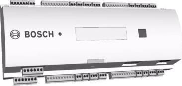
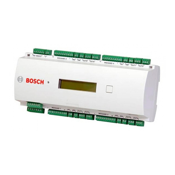
3.1Description of the AMC2 4W
The AMC2 4W (also called AMC2 or controller) is equipped with four independent interfaces for Wiegand type readers. It is able to control two doors with a reader in each direction and up to four doors with a reader in one direction only.
Figure 3.1 The Access Modular Controller AMC2 4W
All necessary information for access verification is stored in a battery buffered on-board memory and a Compact Flash (CF) memory card. This guarantees autonomous access decisions and complete access registrations even if the management host system is offline. The built in compact flash adapter provides adequate storage capability for cardholders and events.
The AMC2 electronics are completely covered by a plastic housing. The liquid crystal display provides all important status information.
Using the AMC2 gives you the full functionality and the offline capability of a complete access control system in each room. This leads to an excellent reliability and a very high redundancy without paying extra money.
|
| V 7.6 | 2008.12 |
Installation manual |
Bosch Sicherheitssysteme GmbH |
|
AMC2 4W |
Introduction | en 13 |
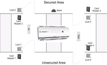
Figure 3.2 The AMC2 4W in a four door safety lock
The AMC2 can communicate upstream to the host computer using RS-485 multi-dropped, RS-232 or 10/100 Mbit/s Ethernet. It has eight analog input devices and eight relay outputs. With its analog input devices, the AMC2 verifies, for example, if a lock is closed or open. The relay outputs can be used to activate lock mechanisms if access is granted, or activate the burglar alarm system if an intrusion or system alert is detected. If the eight inputs and outputs on board are not enough to configure the system, up to three additional extensions (AMC2 8I-8O-EXT, AMC2 16I-EXT, or AMC2 16I-16O-EXT) can be connected. The extensions offer 8 or 16 additional inputs and outputs.
The setup procedure for an AMC2 is made very simple and fast by the use of door templates. Once selected, all the inputs and outputs are predefined. These settings can be changed using the Device Editor (Access Engine) of the BIS Configuration Browser or the Configurator (Access PE) to choose every free contact of the controller or a connected extension.
|
Bosch Sicherheitssysteme GmbH |
Installation manual |
| V 7.6 | 2008.12 |

|
14 en | Introduction |
AMC2 4W |
3.2Equipment Configuration
Figure 3.3 Upper circuit board with display (top side)
1.Internal tamper contact
2.DIL switch for RS-485 address selection, protocol and RS- 232/RS-485 selection
3.Lithium battery for buffering of static RAM and real time clock (RTC). The battery life is estimated at 10 years, nevertheless an error message is generated if the voltage sinks below a preset minimum level.
4.Reset push button — reachable through the casing using a screwdriver
5.Liquid Crystal Display
6.Push button, available on top of the housing, to select different display modes.
7.Jumper: Equalization of potential between different systems and earth ground (shield)
8.Jumper: Interface selector RS-485 Host connection, RS485 two wire or RS-485 four wire (depends on external wiring)
9.Configurable RS-485 host interface
10.Docking port for compact flash memory
11.Configurable RS-232 host interface (ribbon cable connector)
|
| V 7.6 | 2008.12 |
Installation manual |
Bosch Sicherheitssysteme GmbH |

|
AMC2 4W |
Introduction | en 15 |
12. Configurable 10/100 Mbit/s Ethernet interface
Figure 3.4 Overview — Interfaces
13.RS-485 extension module bus
14.External tamper contact
15.Connector for power supply
16.Wiegand interfaces for up to 4 card readers
17.Connectors for eight analog inputs
18.Connectors for eight relay outputs
NOTICE!
All connectors, with the exception of the RS232 and Ethernet host interface, are pluggable screw clamp terminals.
|
Bosch Sicherheitssysteme GmbH |
Installation manual |
| V 7.6 | 2008.12 |
|
16 en | Introduction |
AMC2 4W |
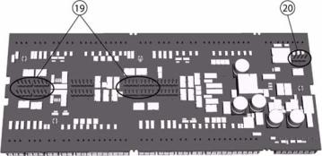
Figure 3.5 Jumper at the bottom side
19.Jumper for setting either voltage free relay output (“dry” mode) or looped-in voltage from the AMC2 internal power supply (“wet” mode).
20.Jumper: Equalization of potential between different systems and earth ground (shield) for the extension interface.
|
| V 7.6 | 2008.12 |
Installation manual |
Bosch Sicherheitssysteme GmbH |
|
AMC2 4W |
Introduction | en 17 |
3.3Performance Characteristics
–Intelligent access manager for 1 … 4 entrances (for example, doors, man traps, barriers)
–Host address selectable using DIL sliding switch
–Four possible configurable host interfaces:
–Ethernet
–RS-485 2-wire
–RS-485 4-wire
–RS-232
–Reader interfaces
–four Wiegand interfaces
–Eight relay outputs
–voltage free, power is supplied externally (dry mode)
–powered by internal power supply (wet mode)
–Eight analog inputs with internal power supply
–Battery buffered SRAM and real time clock (RTC)
–Pluggable Compact Flash from 64 MB to 1024 MB
–Liquid Crystal Display
–Transfer rate host interface RS-485: 38,4 kBit/s
–Transfer rate host interface RS-232: 38,4 kBit/s
–Transfer rate host interface Ethernet: 10/100 Mbit/s
–Transfer rate to the extension interface: 9,6 kBit/s
–Self regulating transmit/receive switching
–Power supply: 10 V to 30 Vdc, max. 5 A
–Tamper contact for internal and external covers
–If an external power supply is used then this should be an PBC-60 (F.01U.026.573) with integrated uninterruptable power supply (UPS).
|
Bosch Sicherheitssysteme GmbH |
Installation manual |
| V 7.6 | 2008.12 |
|
18 en | Introduction |
AMC2 4W |
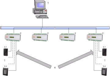
3.4System Overview
The Access Controller AMC2 4W is connected between the management host system and different peripheral devices. By default, a management host system is connected using Ethernet. A management host connection using RS-485 or RS232 is also possible. Corresponding to the available interfaces, one AMC2 can be connected to each COM port using RS-232 mode. In RS-485 mode, up to eight access controllers can be combined on one party line.
Figure 3.6 System overview
|
1 = |
Host |
|
2 = |
AMC2 4W |
|
3 = Wiegand reader (1 — 4) |
4 = Communication and power supply
5 = Ethernet
System Configurations:
–the minimum configuration consists of
–one PC with BIS or Access PE software
–one AMC2 controller
–one AMC PBC-60 power supply
–one AMC enclosure
|
| V 7.6 | 2008.12 |
Installation manual |
Bosch Sicherheitssysteme GmbH |
|
AMC2 4W |
Introduction | en 19 |
–the maximum configuration consists of
–up to two PC’s with shared BIS software [Access PE = one PC]
–up to 200 AMC2 controller [Access PE = 64]
–each controller can be extended with any combination of three AMC2 8I-8O-EXT, AMC2 16I-EXT, or AMC2 16I- 16O-EXT input/output modules [Access PE = one extension board]
–each AMC2 4W controller can be extended with an AMC2 4W-EXT extension module
–the necessary number of AMC PBC-60 power supplies
–the necessary number of AMC enclosures
Using an AMC-MUX interface extension on RS485 host connections it is possible to connect up to eight controllers to a single COM port. Up to 200 AMCs can be connected using the ethernet host connection.
Using Wiegand reader interfaces, up to four peripheral devices can be connected to each AMC2.The interfaces are point-to- point connections, meaning that only one reader can be connected to one interface.
The extension interface supports up to three additional I/O boards (AMC2 8I-8O-EXT, AMC2 16I-EXT, or AMC2 16I-16O-EXT) and one AMC2 4W-EXT. All extension boards are controlled by the AMC2 and are freely combinable.
|
Bosch Sicherheitssysteme GmbH |
Installation manual |
| V 7.6 | 2008.12 |
|
20 en | Technical Data |
AMC2 4W |
4 Technical Data
Hardware
–Integrated Microcontroller (32 bit, 30 MHz)
–SRAM (256 kB)
–Serial EEPROM
–RTC (real time clock)
–Pluggable Compact Flash from 64 MB up to 1 GB
–Battery for SRAM and RTC
–DIL switch for host settings (address and protocol mode)
–Host interfaces
–Ethernet 10/100 Mbit/s
–RS-485 2-wire or 4-wire Transfer rate: 38,4 kBit/s (even parity, 7 bit, 1 stop bit)
–RS-232
Transfer rate: 38,4 kBit/s (no parity, 8 bit, 1 stop bit)
–Four Wiegand interfaces for up to four card readers (Output rating: 280 mA)
–Eight relay outputs
–maximum ratings: switching voltage: 30 Vdc switching current: 1,25 A
–operating ratings: 1,25 A @ 30 Vdc 2 A @ 12 Vdc
1,5 A @ 24 Vdc
–Eight analog inputs with sabotage monitoring; only connect dry contacts
–RS-485 extension interface: Transfer rate: 9,6 kBit/s (no parity, 8 bit, 2 stop bit)
–Tamper contact for enclosures
Power supply
|
| V 7.6 | 2008.12 |
Installation manual |
Bosch Sicherheitssysteme GmbH |
![]()
|
AMC2 4W |
Technical Data | en 21 |
10 to 30 Vdc
Display
64,8 mm x 13,9 mm (2.551 x 0.547 in.)
1 line, 16 characters
Power consumption
AMC: 5 VA
Peripheral devices: using the PBC-60
–up to 55 VA
–constant load: 25 VA
Connectors
Pluggable screw connectors
Protection class
IP30
Environment temperature
0° C to 45° C (32° F to 113° F)
Humidity
Up to 95%, without condensation
Housing material
ABS with OC (UL 94 V-0)
Dimensions
(W/H/D) 232mm x 90mm x 63mm (8.9 x 3.5 x 2.4 in.)
Weight
app. 0,53 kg (0.9 pounds)
WARNING!
!The voltage drop from the power supply to the AMC has effect on the AMC interfaces. Their sum must be less than 2 V!
|
Bosch Sicherheitssysteme GmbH |
Installation manual |
| V 7.6 | 2008.12 |
 Loading…
-
Contents
-
Table of Contents
-
Troubleshooting
-
Bookmarks
Quick Links
Access Modular Controller 2
APC‑AMC2‑4WCF | ADS‑AMC2‑4WCF
en
Installation manual
Related Manuals for Bosch APC‑AMC2‑4WCF
Summary of Contents for Bosch APC‑AMC2‑4WCF
-
Page 1
Access Modular Controller 2 APC‑AMC2‑4WCF | ADS‑AMC2‑4WCF Installation manual… -
Page 3: Table Of Contents
Tamper Protection Operating Status Display of the AMC2 Configuring the Ethernet Interface Troubleshooting 5.3.1 Resetting the Software 5.3.2 Resetting the Device to Factory Default Technical Data Appendices Connecting Diagrams Index Bosch Security Systems B.V. Installation manual 2020-01 | V02 |…
-
Page 4: Safety Instructions
10. Lightning — For added protection during electrical storms external lightning conductors can be installed. This prevents power surges from damaging the unit. 11. The units should be installed in locations with restricted access. 2020-01 | V02 | Installation manual Bosch Security Systems B.V.
-
Page 5: Safety Precautions
0°C to 50°C. Disposal Your Bosch product is designed and manufactured with high-quality materials and components which can be recycled and reused. This symbol means that electrical and electronic equipment, at their end-of-life, should be disposed of separately from your household waste.
-
Page 6: Unpacking
Do not attempt to put the unit into operation if components are damaged. If any parts are missing, inform your customer service representative or a Bosch Security Systems salesperson. The shipping carton is the safest transport container for the unit. Store it and the other packaging material for future use.
-
Page 7: Important Information
Bosch Security Systems retains all rights not expressly granted. Nothing in this license constitutes a waiver of Bosch’s rights under the U.S. Copyright laws or any other federal or state law. If you have any questions concerning this license, please, write to:…
-
Page 8: Introduction
The relay outputs can be used to activate lock mechanisms if access is granted, or activate the burglar alarm system if an intrusion or system alert is detected. If the eight inputs and eight 2020-01 | V02 | Installation manual Bosch Security Systems B.V.
-
Page 9: Equipment Configuration
Jumper: Interface selector RS-485 host connection, RS-485 two wire or RS-485 four wire (depends on external wiring) Configurable RS-485 host interface Docking port for compact flash memory Configurable RS-232 host interface (ribbon cable connector) Configurable 10/100 Mbit/s Ethernet host interface Bosch Security Systems B.V. Installation manual 2020-01 | V02 |…
-
Page 10: Performance Characteristics
Intelligent access manager for 1 — 8 entrances (for example doors, man traps, barriers) – Host address selectable using DIL sliding switch. – Four possible configurable host interfaces: – Ethernet (= standard) – RS-485 2-wire 2020-01 | V02 | Installation manual Bosch Security Systems B.V.
-
Page 11: System Overview
Tamper contact for external covers Notice! If an external power supply is used, this should also guarantee an uninterruptable power supply (UPS). Example: Bosch power supply APS-PSU-60 (F.01U.282.970). System Overview The Access Controller AMC2-4R4 is connected between the management host system and different peripheral devices.
-
Page 12
The extension interface supports up to three additional I/O boards (AMC2-8IOE, AMC2-16IE, or AMC2-16IOE). All extension boards are controlled by the AMC2 and are freely combinable. 2020-01 | V02 | Installation manual Bosch Security Systems B.V. -
Page 13: Installing
Attach the AMC2-4W into the upper edge of the mounting rail [1], then push down the device and snap it onto the rail by pushing it towards the back [2]. Figure 4.1: Mounting the AMC2 on a mounting rail Bosch Security Systems B.V. Installation manual 2020-01 | V02 |…
-
Page 14: Unmounting
Push down the AMC2-4W until the lower edge snaps out of the mounting rail [1]. Pull the lower end of the AMC2-4W from the mounting rail [2]. Figure 4.2: Unmounting the AMC2 from a mounting rail 2020-01 | V02 | Installation manual Bosch Security Systems B.V.
-
Page 15: Opening The Case
The AMC2-4W case consists of a top cover mounted with a two-point snap-in closure on a chassis. To open the case, push down the two snap-ins with a screwdriver, then swing the cover down. Figure 4.3: Opening the AMC2 case Bosch Security Systems B.V. Installation manual 2020-01 | V02 |…
-
Page 16: Closing The Case
[1]. Please ensure that the BOSCH logo is not upside-down. The upper edge of the front cover now aligns with the two-point snap-in closures on the upper edge of the back cover [2], and may thus be clicked gently into place.
-
Page 17
These specifications apply to power supply, readers, relay outputs, and extension interface. Regarding inputs, specific voltage-drop values need to be taken into account. Refer to Connecting Analog Input Devices, page 32. Bosch Security Systems B.V. Installation manual 2020-01 | V02 |… -
Page 18: Grounding And Shielding
JP1 is set at the first device only (= A2) Settings for jumper JP2: If the ground conductor and the shield on the host are not connected and: 2020-01 | V02 | Installation manual Bosch Security Systems B.V.
-
Page 19: Grounding For Extension Interface
Jumper B connects the internal ground of the AMC2-4W to the RS-485 ground of the slave interface. Only set jumper B (B2) if the AMC2-4W powers all other peripheral devices directly connected to it. Bosch Security Systems B.V. Installation manual 2020-01 | V02 |…
-
Page 20: Connecting Power Supply
The battery status is checked every 5 minutes by the power supply unit (APS-PBC-60 or APS- PSU-60). As the battery charging/discharging levels tend to vary, the AMC2 provides information about the battery status every 10 minutes. This feature allows a more reliable battery status information. 2020-01 | V02 | Installation manual Bosch Security Systems B.V.
-
Page 21: Ethernet Host Interface
AMC2 device is recognized by the remote server. You can accelerate this process by running the following command: ipconfig /flushdns This makes the AMC2 device immediately available by its name. Bosch Security Systems B.V. Installation manual 2020-01 | V02 |…
-
Page 22: Rs-485 Host Interface
An RS-485 host system can consist of up to eight AMC2 controllers connected using 2- or 4- wire connection. Figure 4.9: Configuration of a RS-485 host system Host RS-232 connection RS-232 / RS-485 converter RS-485 bus AMC2 controller 2020-01 | V02 | Installation manual Bosch Security Systems B.V.
-
Page 23: Rs-485 Two Wire Connection
RS-485 host interface. The setting of the AMC2-4R4 must correspond with the settings of the RS-232 / RS-485 converter. Figure 4.10: RS-485 host interface 4.9.1 RS-485 Two Wire Connection Figure 4.11: Setting of the jumpers for RS-485 two wire connections Bosch Security Systems B.V. Installation manual 2020-01 | V02 |…
-
Page 24: Rs-485 Four Wire Connection
Figure 4.12: Settings for RS-485 four wire connection Notice! See the notices for setting the RS-232 / RS-485 converter. Notice! If a four-wire connection is used the interface must be set up as a crosslink. 2020-01 | V02 | Installation manual Bosch Security Systems B.V.
-
Page 25: Rs-232 Host Interface
As the AMC2 controller is conceptionally a PC, it is not possible to connect them directly using normal cables. Use instead a null modem or “crossover” cable. A complete connection diagram of the RS-232 host interface is shown in chapter Connecting Diagrams, page 43 Bosch Security Systems B.V. Installation manual 2020-01 | V02 |…
-
Page 26: Dil Switch Selector
– Ethernet host connection – RS-485 host connection, provided only one AMC2 is connected on the bus Set BPA (= DIL switch 5 to OFF) in the case of an 2020-01 | V02 | Installation manual Bosch Security Systems B.V.
-
Page 27: Rs-485 For Extension Modules
You can find further information about the extension boards in their installation manuals. A complete connection diagram of the RS-485 extension module bus is shown in Connecting Diagrams, page 43. Figure 4.16: Connection of an extension module to an AMC2 Bosch Security Systems B.V. Installation manual 2020-01 | V02 |…
-
Page 28: Wiegand Interface For Card Readers
To operate locks or alarm systems, the AMC2-4W has eight relay outputs. The outputs will be connected to the 3-pin pluggable screw connectors S5, S6, S10, S11, S17, S18, S22, and S23 — refer to chapter Connecting Diagrams, page 43. 2020-01 | V02 | Installation manual Bosch Security Systems B.V.
-
Page 29
Wiegand relay types: – Flare move 12DC1W10A – Flare move 24DC1W16A If using locally manufactured products, please ensure that the specifications of the product are identical with the those listed above. Bosch Security Systems B.V. Installation manual 2020-01 | V02 |… -
Page 30
Notice! Risk of damage to equipment Do not connect externally powered devices in wet mode. This can damage the AMC2-4W . 2020-01 | V02 | Installation manual Bosch Security Systems B.V. -
Page 31
(D1) or wet ( D2) mode. Figure 4.21: Location of relay output jumpers (bottom side) Notice! The positions of the jumpers 1 and 2 are interchanged related to the corresponding interfaces. Bosch Security Systems B.V. Installation manual 2020-01 | V02 |… -
Page 32: Connecting Analog Input Devices
The AMC2-4W can also detect the wiring conditions ‘short circuit’ and ‘broken’, and hence trigger an alarm if the appropriate devices are connected. 1. Door open: R 2. Door closed: R 3. Open wire: R = ∞ 4. Short circuit: R 2020-01 | V02 | Installation manual Bosch Security Systems B.V.
-
Page 33
1050 1100 1200 1200 1300 1300 1250 1300 1400 1500 1500 1500 1500 1500 1650 1700 1800 1900 Table 4.2: Maximum values of cable resistance per used resistor combination in Ohm Bosch Security Systems B.V. Installation manual 2020-01 | V02 |… -
Page 34: Tamper Protection
AMC2-4W provides an additional interface to connect external tamper contacts. This interface is a potential-free 2-pin pluggable screw connector marked with T. When not in use this tamper contact should be shorted. Figure 4.23: Location of the tamper protection contact 2020-01 | V02 | Installation manual Bosch Security Systems B.V.
-
Page 35: Operating
Status Display of the AMC2 The liquid crystal display delivers status information about the AMC2-4W . Push the ‘Dialog’ button to switch between different modes. Figure 5.1: Location of the ’Dialog’ button Bosch Security Systems B.V. Installation manual 2020-01 | V02 |…
-
Page 36
+ = online — = offline «C» = Counter of the received data packages from the host interface. RS 485 Bus connection: A = Address 1 … H = Address 8 2020-01 | V02 | Installation manual Bosch Security Systems B.V. -
Page 37: Configuring The Ethernet Interface
Do not use special characters or spaces. The network name must start with a letter. The names are not case sensitive. Notice! Consult the AmcIpConfig tool’s own online help for details on configuring the AMC2-4W . Bosch Security Systems B.V. Installation manual 2020-01 | V02 |…
-
Page 38: Troubleshooting
As soon as it is online again, the AMC2-4W bootloader will download a fresh copy of the application program and configuration. If the problem persists please request technical support. Figure 5.2: Resetting the AMC2 2020-01 | V02 | Installation manual Bosch Security Systems B.V.
-
Page 39: Resetting The Device To Factory Default
IP = [assigned by DHCP server or “0.0.0.0” if not available] – Subnet mask = [assigned by DHCP server or “0.0.0.0” if not available] – Password = no password Figure 5.3: Resetting the AMC2 to delivery state Bosch Security Systems B.V. Installation manual 2020-01 | V02 |…
-
Page 40: Technical Data
64,8 mm x 13,9 mm (2.551 x 0.547 in.) 1 line, 16 characters Power consumption AMC: 5 VA Peripheral devices: using the PSU-60 – up to 55 VA – constant load: 25 VA Connectors Pluggable screw connectors 2020-01 | V02 | Installation manual Bosch Security Systems B.V.
-
Page 41
To determine the environmental impact of an installation, take into account the most extreme values of all participating devices. To determine the vulnerability of an installation, take into account the most restrictive values of all participating devices. Bosch Security Systems B.V. Installation manual 2020-01 | V02 |… -
Page 42
| Technical Data Access Modular Controller 2 2020-01 | V02 | Installation manual Bosch Security Systems B.V. -
Page 43: Appendices
Figure 7.1: Connectors on upper PCB Shield Data RxTx+ (2-wire) Data Rx+ (4-wire) Data RxTx- (2-wire) Data Rx- (4-wire) Ground (PAG) Data Tx+ (4-wire) Data Tx- (4-wire) Tab. 7.3: RS-485 host on upper PCB Bosch Security Systems B.V. Installation manual 2020-01 | V02 |…
-
Page 44
| Appendices Access Modular Controller 2 TXD+ TXD- RXD+ not connected not connected RXD- not connected not connected Tab. 7.4: Ethernet Network socket (RJ45) Figure 7.2: Interconnect diagram of the RS-232 serial interface 2020-01 | V02 | Installation manual Bosch Security Systems B.V. -
Page 45
Access Modular Controller 2 Appendices | en Figure 7.3: Connector blocks of the AMC2-4W Bosch Security Systems B.V. Installation manual 2020-01 | V02 |… -
Page 46
For reader settings refer to the respective reader manual. Analog Input, in Analog Input, out Tab. 7.7: Analog input Relay Output, normally open Relay Output, common Relay Output, normally closed Tab. 7.8: Relay output 2020-01 | V02 | Installation manual Bosch Security Systems B.V. -
Page 47
Power supply for external devices (10V — 30V) Power supply for external devices (0V) Shield Data RxTx+ Data RxTx- Ground (PAG) Tab. 7.9: Host / Extension interface Tamper Contact, in Tamper Contact, out Tab. 7.10: External tamper contact Bosch Security Systems B.V. Installation manual 2020-01 | V02 |… -
Page 48
| Appendices Access Modular Controller 2 2020-01 | V02 | Installation manual Bosch Security Systems B.V. -
Page 49
Access Modular Controller 2 Appendices | en Bosch Security Systems B.V. Installation manual 2020-01 | V02 |… -
Page 50: Index
11 power supply 16, 20 reader interfaces 11, 28, 40 Wiegand 28 resetting 38 resistor 32 RS-232 host interface 10, 25 RS-485 host interface 9, 10, 22 shielding 18 2020-01 | V02 | Installation manual Bosch Security Systems B.V.
-
Page 51
Access Modular Controller 2 Index | Bosch Security Systems B.V. Installation manual 2020-01 | V02 |… -
Page 52
| Index Access Modular Controller 2 2020-01 | V02 | Installation manual Bosch Security Systems B.V. -
Page 54
Bosch Security Systems B.V. Torenallee 49 5617 BA Eindhoven Netherlands www.boschsecurity.com © Bosch Security Systems B.V., 2020…
Устройство:
Bosch Appliances APC-AMC2-4WCF
Размер: 4,78 MB
Добавлено: 2023-05-15
Количество страниц: 60
Как пользоваться?
Наша цель — обеспечить Вам самый быстрый доступ к руководству по эксплуатации устройства Bosch Appliances APC-AMC2-4WCF. Пользуясь просмотром онлайн Вы можете быстро просмотреть содержание и перейти на страницу, на которой найдете решение своей проблемы с Bosch Appliances APC-AMC2-4WCF.
Для Вашего удобства
Если просмотр руководства Bosch Appliances APC-AMC2-4WCF непосредственно на этой странице для Вас неудобен, Вы можете воспользоваться двумя возможными решениями:
- Полноэкранный просмотр -, Чтобы удобно просматривать инструкцию (без скачивания на компьютер) Вы можете использовать режим полноэкранного просмотра. Чтобы запустить просмотр инструкции Bosch Appliances APC-AMC2-4WCF на полном экране, используйте кнопку Полный экран.
- Скачивание на компьютер — Вы можете также скачать инструкцию Bosch Appliances APC-AMC2-4WCF на свой компьютер и сохранить ее в своем архиве. Если ты все же не хотите занимать место на своем устройстве, Вы всегда можете скачать ее из ManualsBase.
Bosch Appliances APC-AMC2-4WCF Руководство пользователя — Online PDF
Ознакомьтесь с подробным руководством пользователя для замечательного творения Bosch Appliances, модель APC-AMC2-4WCF. Получите ценную информацию и инструкции, чтобы максимально использовать возможности вашего устройства и оптимизировать взаимодействие с пользователем. Раскройте весь потенциал своего устройства Bosch Appliances APC-AMC2-4WCF с помощью этого подробного руководства пользователя, в котором содержатся пошаговые инструкции и советы экспертов, которые сделают работу с ним легкой и приятной.
Печатная версия
Многие предпочитают читать документы не на экране, а в печатной версии. Опция распечатки инструкции также предусмотрена и Вы можете воспользоваться ею нажав на ссылку, находящуюся выше — Печатать инструкцию. Вам не обязательно печатать всю инструкцию Bosch Appliances APC-AMC2-4WCF а только некоторые страницы. Берегите бумагу.
Резюме
Ниже Вы найдете заявки которые находятся на очередных страницах инструкции для Bosch Appliances APC-AMC2-4WCF. Если Вы хотите быстро просмотреть содержимое страниц, которые находятся на очередных страницах инструкции, Вы воспользоваться ими.