УСТАНОВКА, ЭКСПЛУАТАЦИЯ И ТЕХОБСЛУЖИВАНИЕ
КОМПЬЮТЕР СЕРИИ BRAVO 400S
СО ВСТРОЕННЫМ GPS-НАВИГАТОРОМ
Версия ПО 2.3X
4674A2XX1
-
Contents
-
Table of Contents
-
Troubleshooting
-
Bookmarks
Quick Links
GPS GUIDANCE MONITOR
4674A0000
Software rel. 2.3X
INSTALLATION, USE AND MAINTENANCE
Related Manuals for ARAG navigator Bravo 400S
Summary of Contents for ARAG navigator Bravo 400S
-
Page 1
GPS GUIDANCE MONITOR 4674A0000 Software rel. 2.3X INSTALLATION, USE AND MAINTENANCE… -
Page 2
This manual is an integral part of the equipment to which it refers and must accompany the equipment in case of sale or change of ownership. Keep it for any future reference; ARAG reserves the right to modify product specifications and instructions at any moment and without notice. -
Page 3: Table Of Contents
CONTENTS Risks and protections before assembly ………4 10.4 General options ………….28 10.4.1 Language …………….28 Intended use …………….4 10.4.2 Unit of measurement …………28 10.4.3 Date and time GPS updating ……….29 Precautions …………….4 10.4.4 Date and Time …………..29 Package content ……………4 10.5 Device status …………..30…
-
Page 4: Risks And Protections Before Assembly
• Comply with the specified power voltage (12 VDC). • In case of voltaic arc welding, remove connectors from Navigator and disconnect the power cables. • Only use ARAG genuine spare parts and accessories. PACKAGE CONTENT The table below indicates the components that you will find in the Navigator package:…
-
Page 5: Position On Farming Machine
INSTALLATION POSITION ON FARMING MACHINE System recommended composition Connect the power cable directly to the battery using the suitable eyelets. WARNING! DO NOT connect to key-operated switch (15/54). SYSTEM FOR GPS GUIDANCE MONITOR Legend of connection cables: Power cable Cameras / spraying activation GPS receiver Fig.
-
Page 6: Wiring Connections
Camera connection Navigator can be connected to one or two cameras code 46700100 (purchased separately) using the suitable cables listed in the ARAG general catalog. Connect the connector to the monitor (see connection points at par. 5.2) and the other cable end to the camera: ensure it is correctly in place and turn the ring nut clockwise until blocking it.
-
Page 7: Setup
SETUP SETUP Setup preparation Before computer setup, check: • that all components are correctly installed; • the correct connection to the power source; • the component connection. Failure to correctly connect system components or to use specified components might damage the device or its components. Switching on SOFTWARE VERSION Keep key pressed until Navigator…
-
Page 8: Switching Off
SETUP Switching off Keep key pressed until Navigator is switched off. During switching off, Navigator automatically saves the current job: Do NOT press any other key and do NOT disconnect the power supply until Navigator turns off. WARNING: ALWAYS use the special key to switch off the device; otherwise ALL data concerning the spraying and the setup will be lost.
-
Page 9: Menu Structure
SETUP MENU STRUCTURE Upon first switching on, press and enter the device basic settings (chap. 9). Afterwards, it will be possible to select the preset settings by pressing chap. 12 «Home» Menu chap. 9 chap. 10 Basic settings Advanced setup Select / Create settings: Edit settings: Implement…
-
Page 10: Basic Settings
SETUP «BASIC SETTINGS» BASIC SETTINGS GUIDED SETUP PROCEDURE UPON FIRST SWITCHING ON 1 LANGUAGE SETTING Settings — In the «Home» screen (Fig. 19) press to enter the menu (Fig. 20). General options > Language — Select and set the language of Navigator. Settings Implement — Press…
-
Page 11
Fig. 24 Fig. 25 Fig. 26 BASIC TRACTOR SETTINGS • A100 : ARAG receiver code 520100.693. • Smart-Ag / Smart 6 : ARAG receivers code 467016xx. • NMEA : all GPS receivers with NMEA183 protocol and with the following features: — 10 Hz GGA message;… -
Page 12: Advanced Setup
ADVANCED SETUP ADVANCED SETUP ACTIVE SETTINGS Before carrying out the advanced setup procedure, select the type of Implement, Tractor and User you wish to use: all modifications made to the advanced setup will be applied to the ACTIVE SETTINGS (in the example here imp00, tra00, usr00). Fig.
-
Page 13
ADVANCED SETUP 3c SETUP SELECTION: Instead of saving, you can select a previously saved setup. imp00 Select the setup from the names on the list ( in the example of Fig. 36: ) and press The selected setup is now active on the computer (Fig. 37). Proceed to advanced setup. Tractor User You can follow the same procedure for… -
Page 14: Implement
ADVANCED SETTINGS «IMPLEMENT» The type of implement displayed depends on the selected basic settings (chap. 9), affecting which items are displayed in Fig. 41. 10.1 Implement Advanced implement settings Sections configuration • (par. 10.1.1). Working parameters • (par. 10.1.2). Carried implement geometry settings Geometry settings •…
-
Page 15: Working Parameters
ADVANCED SETTINGS «IMPLEMENT» 10.1.2 Working parameters Set the farming machine job limits. • Sections overlapping limit Set the acceptable threshold for overlapping of already-sprayed areas. When this threshold is exceeded, Navigator will prompt the operator to close the relevant valves. Fig.
-
Page 16: Spray Closing Delay
ADVANCED SETTINGS «IMPLEMENT» > > > 10.1.2 Working parameters • Spray closing delay Indicate the distance corresponding to the delayed closing of sections during spraying, to ensure correct spraying range. NOTE: Negative values indicate that sections are closed in advance with respect to the calculated point. Closing delay: 0.3 m Fig.
-
Page 17: Reference Line Distance Compensation
ADVANCED SETTINGS «IMPLEMENT» • Reference line distance compensation This value allows changing the distance between the reference tracks. +0.5 m +0.5 m When the value is positive, the distance between the reference tracks (black lines) decreases. The spray lateral sides overlap. Fig.
-
Page 18: Towed Implement Geometry Settings (System With 3-Point Hitch Rear/Front)
ADVANCED SETTINGS «IMPLEMENT» The geometry of the displayed implement depends on the selected basic settings (chap. 9). 10.1.3 Towed implement geometry settings (SYSTEM WITH 3-POINT HITCH REAR/FRONT) Enter farming machine measures: — Press the arrow keys (UP, DOWN, LEFT, RIGHT) to move across different implement views. — Confirm by pressing to enter setup.
-
Page 19: Implement Rear View
ADVANCED SETTINGS «IMPLEMENT» > > > 10.1.3 Towed implement geometry settings (SYSTEM WITH 3-POINT HITCH REAR/FRONT) • Implement rear view — Confirm by pressing to enter setup. — Enter the value. Fig. 65 Fig. 66 Implement width The width set for the implement is shown on the display in the guidance screen: usually it is Implement width 20.00 m equal to the boom width, and thus to the covered area diagram.
-
Page 20: Towed Implement Geometry Settings (System With Towing Hitch)
ADVANCED SETTINGS «IMPLEMENT» The geometry of the displayed implement depends on the selected basic settings (chap. 9). 10.1.4 Towed implement geometry settings (SYSTEM WITH TOWING HITCH) Enter farming machine measures: — Press the arrow keys (UP, DOWN, LEFT, RIGHT) to move across different implement views. — Confirm by pressing to enter setup.
-
Page 21: Implement Rear View
ADVANCED SETTINGS «IMPLEMENT» > > > 10.1.4 Towed implement geometry settings (SYSTEM WITH TOWING HITCH) • Implement rear view — Confirm by pressing to enter setup. — Enter the value. Fig. 73 Fig. 74 Implement width The width set for the implement is shown on the display in the guidance screen: usually it is Implement width 20.00 m equal to the boom width, and thus to the covered area diagram.
-
Page 22: Tractor
10.2.3 Tilt compensation Fig. 79 Fig. 80 Allows to enable/disable the tilt compensation function of the vehicle (with antenna only. See ARAG catalog). Tilt compensation enabled / Tilt compensation disabled). Navigator can set off any measurement errors due to ground inclination.
-
Page 23: Tilt Calibration Procedure
Omnistar correction signal is available worldwide for a fee and allows to obtain high working accuracy. ® WARNING! The differential correction service subscription is not managed by ARAG, but directly by Omnistar ® For more information on the subscription, visit Omnistar ‘s website.
-
Page 24: Camera
ADVANCED SETUP «TRACTOR» 10.2.8 Camera Navigator can connect to up to 2 cameras in order to monitor the working areas that the operator is unable to see (e.g., when driving in reverse). From the menu it is possible to enable/disable each single camera individually or both cameras: No camera connected 1 camera connected to input no.1 1 camera connected to input no.2…
-
Page 25: Tractor Rear View
ADVANCED SETUP «TRACTOR» • Tractor rear view — Press the arrow keys (UP, DOWN, LEFT, RIGHT) to move across values: the description of the selected value will appear on the display. — Confirm by pressing to enter setup. — Enter the value. — Select and enter, one by one, all values.
-
Page 26: User
ADVANCED SETUP «USER» 10.3 User Alarm Navigator features an menu (Fig. 97, accessible from the «Home» menu by pressing ). This page displays all active notifications for the operator. User From the menu it is possible to enable / disable acoustic alarms for each notification: Fig.
-
Page 27: Steering Warning
ADVANCED SETUP «USER» 10.3.4 Steering warning It allows to enable/disable the acoustic signal when the operator must steer in order to align the machine Steering with the following track, avoiding unsprayed or overlapping areas between the two sprays ( radius set in par.
-
Page 28: General Options
ADVANCED SETUP «GENERAL OPTIONS» 10.4 General options Set the device system options: Language • (par. 10.4.1). Unit of measurement • (par. 10.4.2). Date and time GPS updating • (par. 10.4.3). Date and time • (par. 10.4.4). Fig. 106 10.4.1 Language Set the computer language.
-
Page 29: Date And Time Gps Updating
ADVANCED SETUP «GENERAL OPTIONS» 10.4.3 Date and time GPS updating Allows to enable / disable computer automatic date and time updating. Acquisition enabled The local time, date and timezone will be constantly updated thanks to the signal picked up by the GPS receiver.
-
Page 30: Device Status
ADVANCED SETUP «DEVICE STATUS» The aspect of this menu depends on the selected basic settings (chap. 9), which affect which items are displayed in Fig. 111. 10.5 Device status Allows checking the correct operation of Navigator: the description of the selected item will appear on the display.
-
Page 31: Power Supply Data
ADVANCED SETUP «DEVICE STATUS» POWER SUPPLY DATA The device checks the status of the power supply. Fig. 114 FIRMWARE VERSIONS Navigator displays firmware versions. Fig. 115…
-
Page 32: Use
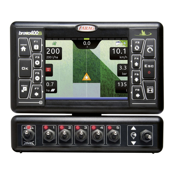
IMPORTANT: Navigator does not control the status of each section: any intervention on the valves must be made separately, by consulting the instruction manual of the relevant control. By communicating what happens on the field, Navigator will collect data on the job. 11.1 Controls on computer Legend:…
-
Page 33: Boom Section Management
11.3 Boom section management Navigator does not automatically manage the closing/opening of sections, which must always be controlled manually. TREATMENT AND BOOM SECTION STATUS Main control OFF Main control OFF Section ON Section OFF Zone to be sprayed Zone already sprayed Sections OFF Sections ON OPEN SECTION…
-
Page 34: Spraying A Field
11.4 Spraying a field • Go the beginning of the field to be sprayed. • Switch Navigator on (par. 7.2). Let us assume we want to spray a field After self-diagnostics, Navigator displays the «Home» along parallel lines, but only once the screen (Fig.
-
Page 35: 12 «Home» Menu
«HOME» MENU — STRUCTURE «HOME» MENU Fig. 127 Home To enter the menu press the key: once inside the menu, pressing each key will enable the corresponding function. The table below sums up all menu items and corresponding keys: Par. Par.
-
Page 36: F1 Continue Last Job
«HOME» MENU — F1 CONTINUE LAST JOB 12.1 Continues last job. Continue last job 1 Press to continue the last job, from the point where it has been interrupted. 2 Select and press to switch to guidance mode. 3 Complete the job (Fig. 129). Fig.
-
Page 37: F2 Save Job
«HOME» MENU — F2 SAVE JOB 12.2 Save current job. Save job Fig. 130 Fig. 131 1 Press to save current job: the name edit screen is displayed (Fig. 130). Type the name. 2A Press in succession to select the character you wish to type (UP / DOWN) 2B Press in succession to select the character you wish to type (RIGHT / LEFT).
-
Page 38: F3 New Job
«HOME» MENU — F3 NEW JOB 12.3 Start a new spraying. New job 1 Press to start a new spraying. If the current job has not been saved yet, Navigator will prompt the user to save it (Fig. 133). Press to continue without saving (2A) or to interrupt the procedure and save (2B).
-
Page 39: Memories Management
«HOME» MENU — F4 MEMORIES MANAGEMENT 12.4 Manages and copies data between internal and external memories (SD card, Pendrive). Memories management Allows to upload, save and/or delete the data memorized on Navigator or on an external memory (SD card / pendrive); said data concern jobs carried out or machine configurations.
-
Page 40: Internal Memory
«HOME» MENU — F4 MEMORIES MANAGEMENT > INTERNAL MEMORY 12.4.1 Internal memory It allows to transfer the saved data (Fig. 139) from the internal memory of Navigator onto an «external» support (SD card or USB pendrive). Implements Tractors, Users, The following paragraphs will use as an example: the same procedure will be valid for all other cases ( etc., Fig.
-
Page 41: Sd Card
«HOME» MENU — F4 MEMORIES MANAGEMENT > SD CARD 12.4.2 SD card It allows transferring the saved data (Fig. 146) from the SD card onto the internal memory of Navigator. Implements Tractors Users The following paragraphs will use as an example: the same procedure will be valid for all other cases ( , etc., Fig.
-
Page 42: Usb Pendrive
«HOME» MENU — F4 MEMORIES MANAGEMENT > USB PENDRIVE 12.4.3 USB pendrive It allows transferring the saved data (Fig. 154) from the pendrive onto the internal memory of Navigator. Implements Tractors Users The following paragraphs will use as an example: the same procedure will be valid for all other cases ( , etc., Fig.
-
Page 43: Exports
«HOME» MENU — F4 MEMORIES MANAGEMENT > EXPORTS 12.4.4 Exports Allows to export saved data to the USB pendrive. • KML on SD It allows to export the current job onto a map in «KML» format and to save it on the USB pendrive. Data in the file can be displayed on a Personal Computer with Google Earth ®…
-
Page 44: F5 Resume Job
«HOME» MENU — F5 RESUME JOB 12.5 Enables procedure for resuming a previously saved job. Resume job 1 Press to resume a previous job, from the list of saved jobs. New job As for the function (par. 12.3), if the current job has not been saved yet, Navigator will prompt the user to save it. 2 Select the job among those in the list (Fig.
-
Page 45: F6 Info / Alarms
«HOME» MENU — F6 INFO / ALARMS 12.6 Displays job information / alarms. Info / Alarms Info / Alarms 1 Press to view the menu (Fig. 167). A description of the selected notification is shown at the bottom of the display. Fig.
-
Page 46: Job Menu
«JOB MENU» — STRUCTURE JOB MENU New job Resume job Continue last job To access job menu start a job ( Menu chap. 12 «Home» Menu); in the guidance screen press In the job menu (Fig. 168), pressing any key at the side will enable the relevant function.
-
Page 47: F1 Info / Alarms
«JOB MENU» — F1 INFO / ALARMS 13.1 Displays job information / alarms. Info / Alarms 1 In the guidance screen, press Menu Info / Alarms 2 Press to view the menu (Fig. 170). A description of the selected notification is shown at the bottom of the display.
-
Page 48: F2 Job Data
«JOB MENU» — F2 JOB DATA 13.2 Displays job data. Job data Menu 1 In the guidance screen, press 2 Press to view the job data (Fig. 172). 3 Press to scroll data. Displayed data and relevant units of measurement are indicated in par. 16.1. A description of the selected data is shown at the bottom of the display.
-
Page 49: F4 Gps Data
(Fig. 174). This screen shows the data sent to the GPS receiver. Enabled for GPS receiver Smart-Ag Tilt model only. (see General ARAG Cat.) A description of the selected data is shown at the bottom of the display. Fig. 173 Fig.
-
Page 50: F5 Camera
«JOB MENU» — F5 CAMERA 13.4 Displays images from connected cameras. Camera Menu 1 In the guidance screen, press Camera 2 Press to view the menu (Fig. 176). By connecting one or more cameras, it is possible to monitor working areas and at the same time view spraying data. Enable camera view during advanced setup (par.
-
Page 51: F7 Zoom All
«JOB MENU» — F7 ZOOM ALL 13.5 Overview of the field during spraying. Zoom all Menu 1 In the guidance screen, press Zoom all 2 Press to view the menu (Fig. 178). Fig. 177 INDICATORS AND POINTS OF INTEREST ON THE FIELD Job interruption point, enabled with the «PAUSE»…
-
Page 52
«JOB MENU» — F7 ZOOM ALL MARKING POINTS OF INTEREST The general points of interest can be memorized with this procedure or with the specific function (par. 14.2.2). It is possible to mark more points. In this screen it is possible to memorize one point of the field even if the tractor is in another position: 1 In field overview screen (Fig. -
Page 53: F8 Menu
«JOB MENU» — F8 MENU 13.6 Job settings menu. Menu Menu 1 In the guidance screen, press Settings menu 2 Press to view the (Fig. 185). In this screen it is possible to access several different menus, which can be useful during spraying: •…
-
Page 54: Job Functions
«JOB FUNCTIONS» — STRUCTURE JOB FUNCTIONS New job Resume job Continue last job To access job functions start a job ( Func chap. 12 «Home» Menu); in the guidance screen press When the list is active (Fig. 186), pressing the key at the side will enable the relevant function.
-
Page 55: F2 Guidance Mode
«JOB FUNCTIONS» — F2 GUIDANCE MODE 14.1 Guidance mode Selecting guidance mode: Func 1 In the guidance screen, press 2 Press to enable the function. 3 Select a guidance mode (Fig. 188): press to move across the available items — Straight guidance mode — Curved guidance mode — Pivot mode — Free guidance mode…
-
Page 56: F3 Point Marking
«JOB FUNCTIONS» — F3 PAUSE 14.2 It groups the available options for marking points of interest. Point marking 1 In the guidance screen, press Func 2 Press . A list with options for marking the points will appear (Fig. 194). Pressing each key will enable the corresponding function.
-
Page 57: F4 Surface
«JOB FUNCTIONS» — F4 SURFACE 14.3 Surface Enables the procedure to calculate field surface by driving along its perimeter. 1 In the guidance screen, press Func 2 Press to start the surface calculation procedure (function list disappears). Field edge side selection The following message will appear: prompting the operator to select which side of the machine to use as a reference to define the field perimeter.
-
Page 58: Resume From Pause
«JOB FUNCTIONS» — F5 RESUME FROM PAUSE Guidance indications to return to job breaking point 14.4 Resume from pause previously saved with function » Pause» (par. 14.2.1). Func 1 In the guidance screen, press 2 Press to obtain guidance information and enable the return to job breaking point procedure The fuchsia line in Fig.
-
Page 59: F6 Align
«JOB FUNCTIONS» — F6 ALIGN Moves the closest reference track, re-aligning it to the position of the machine. 14.5 Align This function is useful when you need to re-align the machine, whilst continuing to drive in the same direction (for example, for corn, sugar cane). Func 1 In the guidance screen, press 2 Press…
-
Page 60: F7 New Ab
«JOB FUNCTIONS» — F7 NEW AB Saves two points A and B on the field, which Navigator uses to draw a line that will act as a 14.6 New AB reference track ( , Fig. 209) for the current job. Func 1 In the guidance screen, press 2 Drive along the stretch you wish to use as a reference for the job.
-
Page 61: F8 Display
«JOB FUNCTIONS» — F8 DISPLAY Allows to select different display modes. Includes several functions: 14.7 Display 1 In the guidance screen, press Func 2 Press . A list of options concerning display modes will appear (Fig. 210). Pressing each key will enable the corresponding function: changes tractor themes (par.
-
Page 62: F4 Spraying Themes
«JOB FUNCTIONS» — F8 DISPLAY 14.7.2 Spraying themes Func 1 In the guidance screen, press 2 Press to view the available options. 3 Press in succession to scroll spraying color combinations. SPRAYING THEME 1 (DEFAULT) Fig. 219 THEME 2 THEME 3 Fig.
-
Page 63: Maintenance / Diagnostics / Repairs
MAINTENANCE / DIAGNOSTICS / REPAIRS MAINTENANCE / DIAGNOSTICS / REPAIRS 15.1 Error messages MESSAGE ON DISPLAY CAUSE REMEDY Wrong connection of receiver cable to Navigator • Check connection to receiver (par. 5.2). GPS receiver not connected! The receiver connection cable is damaged •…
-
Page 64: Technical Data
TECHNICAL DATA TECHNICAL DATA Description Navigator Display LCD 5,7″, 65000 colors, 500 cd/m Rated supply voltage 12 Vdc (9 ÷ 15 Vdc) Consumption (valves excluded) monitor: 0.4 A 0 °C ÷ 45 °C Operating temperature +32 °F ÷ +113 °F -20 °C ÷…
-
Page 65
TECHNICAL DATA > > > 16.1 Data and units of measurement shown Tractor Menu Data Min. Max. DEFAULT Other values that can be set / Notes DGPS Disabled Enabled A100 PDOP alarm 10.0 Tilt Disabled Enabled compensation PDOP alarm 10.0 GPS receiver Smart-Ag / Smart 6 Correction type… -
Page 66: End-Of-Life Disposal
GUARANTEE TERMS 1. ARAG s.r.l. guarantees this apparatus for a period of 360 days (1 year) from the date of sale to the client user (date of the goods delivery note). The components of the apparatus, that in the unappealable opinion of ARAG are faulty due to an original defect in the material or production process, will be repaired or replaced free of charge at the nearest Assistance Center operating at the moment the request for intervention is made.
-
Page 67
Conformity Declaration ARAG s.r.l. Via Palladio, 5/A 42048 Rubiera (RE) — Italy P.IVA 01801480359 Dichiara che il prodotto descrizione: Computer modello: Bravo 400S / Navigator / Navigator LT serie: 4674Axxxx e 4674ACSTExx risponde ai requisiti di conformità contemplati nelle seguenti Direttive Europee: 2004/108/CE (Compatibilità… -
Page 68
Only use genuine ARAG accessories or spare parts to make sure manufacturer guaranteed safety conditions are maintained in time. Always refer to ARAG spare parts catalog. 42048 RUBIERA (Reggio Emilia) — ITALY Via Palladio, 5/A Tel. +39 0522 622011 Fax +39 0522 628944 www.aragnet.com…

УСТАНОВКА, ЭКСПЛУАТАЦИЯ И ТЕХОБСЛУЖИВАНИЕ
4674A9DX0.950
КОМПЬЮТЕР СЕРИИ
BRAVO 400S
СО ВСТРОЕННЫМ GPS-НАВИГАТОРОМ
Версия ПО 2.3X
Вы здесь
Каталог инструкций » A » ARAG » GPS-навигаторы ARAG » ARAG Bravo 400S Crop sprayer » Страница инструкции 1
-

1
-

2
-

3
-

4
-

5
-

6
-

7
-

8
-

9
-

10
-

11
-

12
-

13
-

14
-

15
-

16
-

17
-

18
-

19
-

20
-

21
-

22
-

23
-

24
-

25
-

26
-

27
-

28
-

29
-

30
-

31
-

32
-

33
-

34
-

35
-

36
-

37
-

38
-

39
-

40
-

41
-

42
-

43
-

44
-

45
-

46
-

47
-

48
-

49
-

50
- 1
- 2
- 3
- ››
Распечатать
- << Предыдущая
- Следующая >>

GPS-навигаторы ARAG в инструкции по эксплуатации ARAG Bravo 400S Crop sprayer
УСТАНОВКА ЭКСПЛУАТАЦИЯ И ТЕХОБСЛУЖИВАНИЕ
КОМПЬЮТЕР СЕРИИ BRAVO 400S
СО ВСТРОЕННЫМ GPS-НАВИГАТОРОМ
Версия ПО 2.3X
4674A2XX1
- << Предыдущая
- Следующая >>
-
Page 1
GPS GUIDANCE MONITOR 4674A0000 Software rel. 2.3X INSTALLATION, USE AND MAINTENANCE… -
Page 2
This manual is an integral part of the equipment to which it refers and must accompany the equipment in case of sale or change of ownership. Keep it for any future reference; ARAG reserves the right to modify product specifications and instructions at any moment and without notice. -
Page 3: Table Of Contents
CONTENTS Risks and protections before assembly ………4 10.4 General options ………….28 10.4.1 Language …………….28 Intended use …………….4 10.4.2 Unit of measurement …………28 10.4.3 Date and time GPS updating ……….29 Precautions …………….4 10.4.4 Date and Time …………..29 Package content ……………4 10.5 Device status …………..30…
-
Page 4: Risks And Protections Before Assembly
• Comply with the specified power voltage (12 VDC). • In case of voltaic arc welding, remove connectors from Navigator and disconnect the power cables. • Only use ARAG genuine spare parts and accessories. PACKAGE CONTENT The table below indicates the components that you will find in the Navigator package:…
-
Page 5: Position On Farming Machine
INSTALLATION POSITION ON FARMING MACHINE System recommended composition Connect the power cable directly to the battery using the suitable eyelets. WARNING! DO NOT connect to key-operated switch (15/54). SYSTEM FOR GPS GUIDANCE MONITOR Legend of connection cables: Power cable Cameras / spraying activation GPS receiver Fig.
-
Page 6: Wiring Connections
Camera connection Navigator can be connected to one or two cameras code 46700100 (purchased separately) using the suitable cables listed in the ARAG general catalog. Connect the connector to the monitor (see connection points at par. 5.2) and the other cable end to the camera: ensure it is correctly in place and turn the ring nut clockwise until blocking it.
-
Page 7: Setup
SETUP SETUP Setup preparation Before computer setup, check: • that all components are correctly installed; • the correct connection to the power source; • the component connection. Failure to correctly connect system components or to use specified components might damage the device or its components. Switching on SOFTWARE VERSION Keep key pressed until Navigator…
-
Page 8: Switching Off
SETUP Switching off Keep key pressed until Navigator is switched off. During switching off, Navigator automatically saves the current job: Do NOT press any other key and do NOT disconnect the power supply until Navigator turns off. WARNING: ALWAYS use the special key to switch off the device; otherwise ALL data concerning the spraying and the setup will be lost.
-
Page 9: Menu Structure
SETUP MENU STRUCTURE Upon first switching on, press and enter the device basic settings (chap. 9). Afterwards, it will be possible to select the preset settings by pressing chap. 12 «Home» Menu chap. 9 chap. 10 Basic settings Advanced setup Select / Create settings: Edit settings: Implement…
-
Page 10: Basic Settings
SETUP «BASIC SETTINGS» BASIC SETTINGS GUIDED SETUP PROCEDURE UPON FIRST SWITCHING ON 1 LANGUAGE SETTING Settings — In the «Home» screen (Fig. 19) press to enter the menu (Fig. 20). General options > Language — Select and set the language of Navigator. Settings Implement — Press…
-
Page 11
Fig. 24 Fig. 25 Fig. 26 BASIC TRACTOR SETTINGS • A100 : ARAG receiver code 520100.693. • Smart-Ag / Smart 6 : ARAG receivers code 467016xx. • NMEA : all GPS receivers with NMEA183 protocol and with the following features: — 10 Hz GGA message;… -
Page 12: Advanced Setup
ADVANCED SETUP ADVANCED SETUP ACTIVE SETTINGS Before carrying out the advanced setup procedure, select the type of Implement, Tractor and User you wish to use: all modifications made to the advanced setup will be applied to the ACTIVE SETTINGS (in the example here imp00, tra00, usr00). Fig.
-
Page 13
ADVANCED SETUP 3c SETUP SELECTION: Instead of saving, you can select a previously saved setup. imp00 Select the setup from the names on the list ( in the example of Fig. 36: ) and press The selected setup is now active on the computer (Fig. 37). Proceed to advanced setup. Tractor User You can follow the same procedure for… -
Page 14: Implement
ADVANCED SETTINGS «IMPLEMENT» The type of implement displayed depends on the selected basic settings (chap. 9), affecting which items are displayed in Fig. 41. 10.1 Implement Advanced implement settings Sections configuration • (par. 10.1.1). Working parameters • (par. 10.1.2). Carried implement geometry settings Geometry settings •…
-
Page 15: Working Parameters
ADVANCED SETTINGS «IMPLEMENT» 10.1.2 Working parameters Set the farming machine job limits. • Sections overlapping limit Set the acceptable threshold for overlapping of already-sprayed areas. When this threshold is exceeded, Navigator will prompt the operator to close the relevant valves. Fig.
-
Page 16: Spray Closing Delay
ADVANCED SETTINGS «IMPLEMENT» > > > 10.1.2 Working parameters • Spray closing delay Indicate the distance corresponding to the delayed closing of sections during spraying, to ensure correct spraying range. NOTE: Negative values indicate that sections are closed in advance with respect to the calculated point. Closing delay: 0.3 m Fig.
-
Page 17: Reference Line Distance Compensation
ADVANCED SETTINGS «IMPLEMENT» • Reference line distance compensation This value allows changing the distance between the reference tracks. +0.5 m +0.5 m When the value is positive, the distance between the reference tracks (black lines) decreases. The spray lateral sides overlap. Fig.
-
Page 18: Towed Implement Geometry Settings (System With 3-Point Hitch Rear/Front)
ADVANCED SETTINGS «IMPLEMENT» The geometry of the displayed implement depends on the selected basic settings (chap. 9). 10.1.3 Towed implement geometry settings (SYSTEM WITH 3-POINT HITCH REAR/FRONT) Enter farming machine measures: — Press the arrow keys (UP, DOWN, LEFT, RIGHT) to move across different implement views. — Confirm by pressing to enter setup.
-
Page 19: Implement Rear View
ADVANCED SETTINGS «IMPLEMENT» > > > 10.1.3 Towed implement geometry settings (SYSTEM WITH 3-POINT HITCH REAR/FRONT) • Implement rear view — Confirm by pressing to enter setup. — Enter the value. Fig. 65 Fig. 66 Implement width The width set for the implement is shown on the display in the guidance screen: usually it is Implement width 20.00 m equal to the boom width, and thus to the covered area diagram.
-
Page 20: Towed Implement Geometry Settings (System With Towing Hitch)
ADVANCED SETTINGS «IMPLEMENT» The geometry of the displayed implement depends on the selected basic settings (chap. 9). 10.1.4 Towed implement geometry settings (SYSTEM WITH TOWING HITCH) Enter farming machine measures: — Press the arrow keys (UP, DOWN, LEFT, RIGHT) to move across different implement views. — Confirm by pressing to enter setup.
-
Page 21: Implement Rear View
ADVANCED SETTINGS «IMPLEMENT» > > > 10.1.4 Towed implement geometry settings (SYSTEM WITH TOWING HITCH) • Implement rear view — Confirm by pressing to enter setup. — Enter the value. Fig. 73 Fig. 74 Implement width The width set for the implement is shown on the display in the guidance screen: usually it is Implement width 20.00 m equal to the boom width, and thus to the covered area diagram.
-
Page 22: Tractor
10.2.3 Tilt compensation Fig. 79 Fig. 80 Allows to enable/disable the tilt compensation function of the vehicle (with antenna only. See ARAG catalog). Tilt compensation enabled / Tilt compensation disabled). Navigator can set off any measurement errors due to ground inclination.
-
Page 23: Tilt Calibration Procedure
Omnistar correction signal is available worldwide for a fee and allows to obtain high working accuracy. ® WARNING! The differential correction service subscription is not managed by ARAG, but directly by Omnistar ® For more information on the subscription, visit Omnistar ‘s website.
-
Page 24: Camera
ADVANCED SETUP «TRACTOR» 10.2.8 Camera Navigator can connect to up to 2 cameras in order to monitor the working areas that the operator is unable to see (e.g., when driving in reverse). From the menu it is possible to enable/disable each single camera individually or both cameras: No camera connected 1 camera connected to input no.1 1 camera connected to input no.2…
-
Page 25: Tractor Rear View
ADVANCED SETUP «TRACTOR» • Tractor rear view — Press the arrow keys (UP, DOWN, LEFT, RIGHT) to move across values: the description of the selected value will appear on the display. — Confirm by pressing to enter setup. — Enter the value. — Select and enter, one by one, all values.
-
Page 26: User
ADVANCED SETUP «USER» 10.3 User Alarm Navigator features an menu (Fig. 97, accessible from the «Home» menu by pressing ). This page displays all active notifications for the operator. User From the menu it is possible to enable / disable acoustic alarms for each notification: Fig.
-
Page 27: Steering Warning
ADVANCED SETUP «USER» 10.3.4 Steering warning It allows to enable/disable the acoustic signal when the operator must steer in order to align the machine Steering with the following track, avoiding unsprayed or overlapping areas between the two sprays ( radius set in par.
-
Page 28: General Options
ADVANCED SETUP «GENERAL OPTIONS» 10.4 General options Set the device system options: Language • (par. 10.4.1). Unit of measurement • (par. 10.4.2). Date and time GPS updating • (par. 10.4.3). Date and time • (par. 10.4.4). Fig. 106 10.4.1 Language Set the computer language.
-
Page 29: Date And Time Gps Updating
ADVANCED SETUP «GENERAL OPTIONS» 10.4.3 Date and time GPS updating Allows to enable / disable computer automatic date and time updating. Acquisition enabled The local time, date and timezone will be constantly updated thanks to the signal picked up by the GPS receiver.
-
Page 30: Device Status
ADVANCED SETUP «DEVICE STATUS» The aspect of this menu depends on the selected basic settings (chap. 9), which affect which items are displayed in Fig. 111. 10.5 Device status Allows checking the correct operation of Navigator: the description of the selected item will appear on the display.
-
Page 31: Power Supply Data
ADVANCED SETUP «DEVICE STATUS» POWER SUPPLY DATA The device checks the status of the power supply. Fig. 114 FIRMWARE VERSIONS Navigator displays firmware versions. Fig. 115…
-
Page 32: Use
IMPORTANT: Navigator does not control the status of each section: any intervention on the valves must be made separately, by consulting the instruction manual of the relevant control. By communicating what happens on the field, Navigator will collect data on the job. 11.1 Controls on computer Legend:…
-
Page 33: Boom Section Management
11.3 Boom section management Navigator does not automatically manage the closing/opening of sections, which must always be controlled manually. TREATMENT AND BOOM SECTION STATUS Main control OFF Main control OFF Section ON Section OFF Zone to be sprayed Zone already sprayed Sections OFF Sections ON OPEN SECTION…
-
Page 34: Spraying A Field
11.4 Spraying a field • Go the beginning of the field to be sprayed. • Switch Navigator on (par. 7.2). Let us assume we want to spray a field After self-diagnostics, Navigator displays the «Home» along parallel lines, but only once the screen (Fig.
-
Page 35: 12 «Home» Menu
«HOME» MENU — STRUCTURE «HOME» MENU Fig. 127 Home To enter the menu press the key: once inside the menu, pressing each key will enable the corresponding function. The table below sums up all menu items and corresponding keys: Par. Par.
-
Page 36: F1 Continue Last Job
«HOME» MENU — F1 CONTINUE LAST JOB 12.1 Continues last job. Continue last job 1 Press to continue the last job, from the point where it has been interrupted. 2 Select and press to switch to guidance mode. 3 Complete the job (Fig. 129). Fig.
-
Page 37: F2 Save Job
«HOME» MENU — F2 SAVE JOB 12.2 Save current job. Save job Fig. 130 Fig. 131 1 Press to save current job: the name edit screen is displayed (Fig. 130). Type the name. 2A Press in succession to select the character you wish to type (UP / DOWN) 2B Press in succession to select the character you wish to type (RIGHT / LEFT).
-
Page 38: F3 New Job
«HOME» MENU — F3 NEW JOB 12.3 Start a new spraying. New job 1 Press to start a new spraying. If the current job has not been saved yet, Navigator will prompt the user to save it (Fig. 133). Press to continue without saving (2A) or to interrupt the procedure and save (2B).
-
Page 39: Memories Management
«HOME» MENU — F4 MEMORIES MANAGEMENT 12.4 Manages and copies data between internal and external memories (SD card, Pendrive). Memories management Allows to upload, save and/or delete the data memorized on Navigator or on an external memory (SD card / pendrive); said data concern jobs carried out or machine configurations.
-
Page 40: Internal Memory
«HOME» MENU — F4 MEMORIES MANAGEMENT > INTERNAL MEMORY 12.4.1 Internal memory It allows to transfer the saved data (Fig. 139) from the internal memory of Navigator onto an «external» support (SD card or USB pendrive). Implements Tractors, Users, The following paragraphs will use as an example: the same procedure will be valid for all other cases ( etc., Fig.
-
Page 41: Sd Card
«HOME» MENU — F4 MEMORIES MANAGEMENT > SD CARD 12.4.2 SD card It allows transferring the saved data (Fig. 146) from the SD card onto the internal memory of Navigator. Implements Tractors Users The following paragraphs will use as an example: the same procedure will be valid for all other cases ( , etc., Fig.
-
Page 42: Usb Pendrive
«HOME» MENU — F4 MEMORIES MANAGEMENT > USB PENDRIVE 12.4.3 USB pendrive It allows transferring the saved data (Fig. 154) from the pendrive onto the internal memory of Navigator. Implements Tractors Users The following paragraphs will use as an example: the same procedure will be valid for all other cases ( , etc., Fig.
-
Page 43: Exports
«HOME» MENU — F4 MEMORIES MANAGEMENT > EXPORTS 12.4.4 Exports Allows to export saved data to the USB pendrive. • KML on SD It allows to export the current job onto a map in «KML» format and to save it on the USB pendrive. Data in the file can be displayed on a Personal Computer with Google Earth ®…
-
Page 44: F5 Resume Job
«HOME» MENU — F5 RESUME JOB 12.5 Enables procedure for resuming a previously saved job. Resume job 1 Press to resume a previous job, from the list of saved jobs. New job As for the function (par. 12.3), if the current job has not been saved yet, Navigator will prompt the user to save it. 2 Select the job among those in the list (Fig.
-
Page 45: F6 Info / Alarms
«HOME» MENU — F6 INFO / ALARMS 12.6 Displays job information / alarms. Info / Alarms Info / Alarms 1 Press to view the menu (Fig. 167). A description of the selected notification is shown at the bottom of the display. Fig.
-
Page 46: Job Menu
«JOB MENU» — STRUCTURE JOB MENU New job Resume job Continue last job To access job menu start a job ( Menu chap. 12 «Home» Menu); in the guidance screen press In the job menu (Fig. 168), pressing any key at the side will enable the relevant function.
-
Page 47: F1 Info / Alarms
«JOB MENU» — F1 INFO / ALARMS 13.1 Displays job information / alarms. Info / Alarms 1 In the guidance screen, press Menu Info / Alarms 2 Press to view the menu (Fig. 170). A description of the selected notification is shown at the bottom of the display.
-
Page 48: F2 Job Data
«JOB MENU» — F2 JOB DATA 13.2 Displays job data. Job data Menu 1 In the guidance screen, press 2 Press to view the job data (Fig. 172). 3 Press to scroll data. Displayed data and relevant units of measurement are indicated in par. 16.1. A description of the selected data is shown at the bottom of the display.
-
Page 49: F4 Gps Data
(Fig. 174). This screen shows the data sent to the GPS receiver. Enabled for GPS receiver Smart-Ag Tilt model only. (see General ARAG Cat.) A description of the selected data is shown at the bottom of the display. Fig. 173 Fig.
-
Page 50: F5 Camera
«JOB MENU» — F5 CAMERA 13.4 Displays images from connected cameras. Camera Menu 1 In the guidance screen, press Camera 2 Press to view the menu (Fig. 176). By connecting one or more cameras, it is possible to monitor working areas and at the same time view spraying data. Enable camera view during advanced setup (par.
-
Page 51: F7 Zoom All
«JOB MENU» — F7 ZOOM ALL 13.5 Overview of the field during spraying. Zoom all Menu 1 In the guidance screen, press Zoom all 2 Press to view the menu (Fig. 178). Fig. 177 INDICATORS AND POINTS OF INTEREST ON THE FIELD Job interruption point, enabled with the «PAUSE»…
-
Page 52
«JOB MENU» — F7 ZOOM ALL MARKING POINTS OF INTEREST The general points of interest can be memorized with this procedure or with the specific function (par. 14.2.2). It is possible to mark more points. In this screen it is possible to memorize one point of the field even if the tractor is in another position: 1 In field overview screen (Fig. -
Page 53: F8 Menu
«JOB MENU» — F8 MENU 13.6 Job settings menu. Menu Menu 1 In the guidance screen, press Settings menu 2 Press to view the (Fig. 185). In this screen it is possible to access several different menus, which can be useful during spraying: •…
-
Page 54: Job Functions
«JOB FUNCTIONS» — STRUCTURE JOB FUNCTIONS New job Resume job Continue last job To access job functions start a job ( Func chap. 12 «Home» Menu); in the guidance screen press When the list is active (Fig. 186), pressing the key at the side will enable the relevant function.
-
Page 55: F2 Guidance Mode
«JOB FUNCTIONS» — F2 GUIDANCE MODE 14.1 Guidance mode Selecting guidance mode: Func 1 In the guidance screen, press 2 Press to enable the function. 3 Select a guidance mode (Fig. 188): press to move across the available items — Straight guidance mode — Curved guidance mode — Pivot mode — Free guidance mode…
-
Page 56: F3 Point Marking
«JOB FUNCTIONS» — F3 PAUSE 14.2 It groups the available options for marking points of interest. Point marking 1 In the guidance screen, press Func 2 Press . A list with options for marking the points will appear (Fig. 194). Pressing each key will enable the corresponding function.
-
Page 57: F4 Surface
«JOB FUNCTIONS» — F4 SURFACE 14.3 Surface Enables the procedure to calculate field surface by driving along its perimeter. 1 In the guidance screen, press Func 2 Press to start the surface calculation procedure (function list disappears). Field edge side selection The following message will appear: prompting the operator to select which side of the machine to use as a reference to define the field perimeter.
-
Page 58: Resume From Pause
«JOB FUNCTIONS» — F5 RESUME FROM PAUSE Guidance indications to return to job breaking point 14.4 Resume from pause previously saved with function » Pause» (par. 14.2.1). Func 1 In the guidance screen, press 2 Press to obtain guidance information and enable the return to job breaking point procedure The fuchsia line in Fig.
-
Page 59: F6 Align
«JOB FUNCTIONS» — F6 ALIGN Moves the closest reference track, re-aligning it to the position of the machine. 14.5 Align This function is useful when you need to re-align the machine, whilst continuing to drive in the same direction (for example, for corn, sugar cane). Func 1 In the guidance screen, press 2 Press…
-
Page 60: F7 New Ab
«JOB FUNCTIONS» — F7 NEW AB Saves two points A and B on the field, which Navigator uses to draw a line that will act as a 14.6 New AB reference track ( , Fig. 209) for the current job. Func 1 In the guidance screen, press 2 Drive along the stretch you wish to use as a reference for the job.
-
Page 61: F8 Display
«JOB FUNCTIONS» — F8 DISPLAY Allows to select different display modes. Includes several functions: 14.7 Display 1 In the guidance screen, press Func 2 Press . A list of options concerning display modes will appear (Fig. 210). Pressing each key will enable the corresponding function: changes tractor themes (par.
-
Page 62: F4 Spraying Themes
«JOB FUNCTIONS» — F8 DISPLAY 14.7.2 Spraying themes Func 1 In the guidance screen, press 2 Press to view the available options. 3 Press in succession to scroll spraying color combinations. SPRAYING THEME 1 (DEFAULT) Fig. 219 THEME 2 THEME 3 Fig.
-
Page 63: Maintenance / Diagnostics / Repairs
MAINTENANCE / DIAGNOSTICS / REPAIRS MAINTENANCE / DIAGNOSTICS / REPAIRS 15.1 Error messages MESSAGE ON DISPLAY CAUSE REMEDY Wrong connection of receiver cable to Navigator • Check connection to receiver (par. 5.2). GPS receiver not connected! The receiver connection cable is damaged •…
-
Page 64: Technical Data
TECHNICAL DATA TECHNICAL DATA Description Navigator Display LCD 5,7″, 65000 colors, 500 cd/m Rated supply voltage 12 Vdc (9 ÷ 15 Vdc) Consumption (valves excluded) monitor: 0.4 A 0 °C ÷ 45 °C Operating temperature +32 °F ÷ +113 °F -20 °C ÷…
-
Page 65
TECHNICAL DATA > > > 16.1 Data and units of measurement shown Tractor Menu Data Min. Max. DEFAULT Other values that can be set / Notes DGPS Disabled Enabled A100 PDOP alarm 10.0 Tilt Disabled Enabled compensation PDOP alarm 10.0 GPS receiver Smart-Ag / Smart 6 Correction type… -
Page 66: End-Of-Life Disposal
GUARANTEE TERMS 1. ARAG s.r.l. guarantees this apparatus for a period of 360 days (1 year) from the date of sale to the client user (date of the goods delivery note). The components of the apparatus, that in the unappealable opinion of ARAG are faulty due to an original defect in the material or production process, will be repaired or replaced free of charge at the nearest Assistance Center operating at the moment the request for intervention is made.
-
Page 67
Conformity Declaration ARAG s.r.l. Via Palladio, 5/A 42048 Rubiera (RE) — Italy P.IVA 01801480359 Dichiara che il prodotto descrizione: Computer modello: Bravo 400S / Navigator / Navigator LT serie: 4674Axxxx e 4674ACSTExx risponde ai requisiti di conformità contemplati nelle seguenti Direttive Europee: 2004/108/CE (Compatibilità… -
Page 68
Only use genuine ARAG accessories or spare parts to make sure manufacturer guaranteed safety conditions are maintained in time. Always refer to ARAG spare parts catalog. 42048 RUBIERA (Reggio Emilia) — ITALY Via Palladio, 5/A Tel. +39 0522 622011 Fax +39 0522 628944 www.aragnet.com…