-
Contents
-
Table of Contents
-
Bookmarks
Quick Links
Chapters
-
Control and Display Elements, Operating Modes T C
32 -
Installation T C
40 -
Start-Up and Operation of the Position Controller Type 8692 T C
52 -
Start-Up and Operation of the Position Controller Type 8693 T C
92 -
Profibus-Dp T C
126 -
Devicenet T C
140 -
Servicing and Troubleshooting the Process Controller Type 8693 T C
162 -
General Rules (Appendix) T C
168
Related Manuals for Burkert 8692
Summary of Contents for Burkert 8692
-
Page 2
Type 8692, 8693 Positioner Electropneumatic positioner Operating Instructions Bedienungsanleitung Manuel d‘ utilisation… -
Page 3
We reserve the right to make technical changes without notice. Technische Änderungen vorbehalten. Sous resérve de modification techniques. © 2008 Bürkert Werke GmbH & Co. KG Operating Instructions 0804/00_EU-ML_00806169… -
Page 4
Electrical Connection — Multipole Plug Model ……………………….42 Electrical Connection — Terminal Model for Cable Gland ………………….45 Initial Start-up ………………………………….48 START-UP AND OPERATION OF THE POSITION CONTROLLER TYPE 8692 ……………….51 Safety instructions ………………………………..53 Starting up and installing the position controller Type 8692 …………………54 Operation of the position controllerS …………………………60… -
Page 5
Configuration of the Process Data…………………………..148 Bus Status Display ………………………………..151 Configuration Example 1 ………………………………152 Configuration Example 2 ………………………………155 SERVICING AND TROUBLESHOOTING THE POSITION CONTROLLER TYPE 8692 …………..157 Maintenance ………………………………….158 Error Messages and Malfunctions……………………………158 SERVICING AND TROUBLESHOOTING THE PROCESS CONTROLLER TYPE 8693 …………..161 Maintenance ………………………………….162… -
Page 6
Adjustment rules for PID Controllers …………………………175 OPERATING STRUCTURE OF THE POSITIONER (APPENDIX) ………………….179 Operating Structure of the Positioner …………………………180 POSITION CONTROLLER TABLE TYPE 8692 (APPENDIX) ……………………187 Table for Your Settings on the Position Controller ……………………188 PROCESS CONTROLLER TABLE TYPE 8693 (APPENDIX) ……………………189 Table for Your Settings on the Process Controller ……………………190… -
Page 7
Type 8692, 8693 Table of Contents english… -
Page 8
Type 8692, 8693 General Information Safety Instructions General Information and Safety Instructions ABLE OF ONTENTS THE OPERATING INSTRUCTIONS …………………………….. 8 Symbols …………………………………….. 8 INTENDED USE ……………………………………9 Restrictions ……………………………………9 Foreseeable Misuse ………………………………..9 GENERAL SAFETY INSTRUCTIONS …………………………….10 GENERAL INFORMATION ………………………………..11 Scope of supply …………………………………..11… -
Page 9
Type 8692, 8693 General Information Safety Instructions 1 THE OPERATING INSTRUCTIONS The operating instructions describe the entire life cycle of the device. Keep these instructions in a location which is easily acces- sible to every user and make these instructions available to every new owner of the device. -
Page 10
If exporting the system/device, observe any existing restrictions. 2.2 Foreseeable Misuse • The positioner Type 8692 and Type 8693 must not be used in areas where there is a risk of explosion. • Do not introduce any aggressive or flammable media into the system’s media connections. -
Page 11
Also ensure that you do not touch electronic components when the power supply voltage is present! The positioners Type 8692 and Type 8693 were developed with due consideration given to the accepted safety rules and are state-of-the-art. However, dangers can still arise. -
Page 12
This document does not offer any form of warranty. Please refer to our general terms of sales and business. The warranty is only valid if the positioner Type 8692 and Type 8693 is used as intended in accordance with the specified application conditions. -
Page 13
Type 8692, 8693 General Information Safety Instructions english… -
Page 14
Features ……………………………………17 Function diagram of the positioner with single-acting actuator ……………….18 TYPE 8692 POSITIONER WITH POSITION CONTROLLER ……………………19 Schematic representation of the positioner Type 8692 ………………….20 Properties of the position controller software ……………………..21 TYPE 8693 POSITIONER WITH PROCESS CONTROLLER ……………………22 Schematic representation of the process control ……………………23… -
Page 15
1 FUNCTION OF THE POSITIONER AND COMBINATION WITH VALVE TYPES Positioners Type 8692 and Type 8693 are electropneumatic positioner for pneumatically actuated control valves with single- acting or double-acting actuators. Together with the pneumatic actuator the positioner forms an optical and functional unit. -
Page 16
Type 8692, 8693 Description of System Pneumatically actuated piston actuators and rotary actuators can be used as a actuator. Both single-acting and double-acting actuators are offered in combination with the positioner. For single-acting actuators, only one chamber is aerated and deaerated during actuation. The generated pressure works against a spring. -
Page 17
Description of System 2 STRUCTURE OF THE POSITIONER The positioners Type 8692 and Type 8693 consist of the micro-processor controlled electronics, the position measuring system and the control system. The appliance is designed using three-wire technology. Operation of the positioner is controlled by four keys and a 128×64 dot matrix graphic display. -
Page 18
Type 8692, 8693 Description of System 2.2 Features • Models for single-acting or double-acting valve actuators. • Position measuring system Non-contact and therefore non-wearing position measuring system. • Microprocessor-controlled electronics for signal processing, control and valve control. • Control module Operation of the device is controlled by four keys. -
Page 19
Description of System 2.3 Function diagram of the positioner with single-acting actuator The black lines describe the function of the position controller (Type 8692). The process controller (Type 8693) includes the position controller and the functions which are illustrated in grey. -
Page 20
Type 8692, 8693 Description of System 3 TYPE 8692 POSITIONER WITH POSITION CONTROLLER The position measuring system records the current position (POS) of the pneumatic actuator. The position controller compares this actual position value with the set-point value (CMD), which is definable as norm signal. In case of a control deviation (Xd1), a pulse-width modulated voltage signal is sent to the control system as a manipulated variable. -
Page 21
Type 8692, 8693 Description of System 3.1 Schematic representation of the positioner Type 8692 Fig. 5: Schematic representation of position control english… -
Page 22
Type 8692, 8693 Description of System 3.2 Properties of the position controller software Additional function Action Position controller with additional function Sealing function Valve closes tight outside the control range. Specification of the value (in %), from which the actuator is completely de- CUTOFF aerated (when 0%) or aerated (when 100%). -
Page 23
Type 8692, 8693 Description of System 4 TYPE 8693 POSITIONER WITH PROCESS CONTROLLER If the positioner is operated with process controller Type 8693, the aforementioned position control becomes the subordinate auxiliary control circuit; this results in a cascade control. The process controller in the main control circuit of the positioner has a PID function. -
Page 24
Type 8692, 8693 Description of System 4.1 Schematic representation of the process control Fig. 7: Schematic representation of process control english… -
Page 25
Type 8692, 8693 Description of System 4.2 Properties of the process controller software Additional function Action Position controller with additional function Sealing function Valve closes tight outside the control range. Specification of the value (in %), from which the actuator is completely deaerated CUTOFF (when 0%) or aerated (when 100%). -
Page 26
Frequency Pt100 Binary input 24 V DC Operation Fig. 10: Interfaces for the multipole model The positioners Type 8692 and Type 8693 are 3-wire devices, i.e. the power (24 V DC) is supplied separately from the set-point value signal. english… -
Page 27
Operation Fig. 11: Interfaces for the model with cable gland The positioners Type 8692 and Type 8693 are 3-wire devices, i.e. the power (24 V DC) is supplied separately from the set-point value signal. *Type 8693: The switch can be used to supply power to a connected sensor… -
Page 28
Type 8692, 8693 Description of System 7 TECHNICAL DATA Safety positions after failure of the electrical or pneumatic auxiliary power Safety positions after failure of the auxiliary power Actuator system Designation electrical pneumatic single-acting down down control function A down… -
Page 29
Type 8692, 8693 Description of System 7.2 Factory settings of the positioner Function Factory setting Function Factory setting ACTUATOR SINGLE or DOUBLE* X.CONTROL DBND 1.0 % INPUT 4-20 mA KXopn (1) Values of X.TUNE determined KXcls (1) Values of X.TUNE determined… -
Page 30
Type 8692, 8693 Description of System 7.3 Specifications of the Positioner 7.3.1 Operating Conditions CAUTION! If used outside, the device may be exposed to direct sunlight and temperature fluctuations which may cause mal- functions or leaks! • The device must not be used outside. -
Page 31
Type 8692, 8693 Description of System 7.3.5 Pneumatic Data Control medium Quality classes in accordance with DIN ISO 8573-1 Dust content Class 5 max. particle size 40 µm, max. particle density 10 mg/m³ Water content Class 3 max. pressure dew point — 20 °C or min. -
Page 32: Table Of Contents
Configuration of the keys ………………………………33 Information on the Display ……………………………..34 OPERATING MODES ………………………………….35 Operating state ………………………………….35 AUTOMATIC Operating State for Type 8692 ……………………….35 AUTOMATIC Operating State for Type 8693 ……………………….36 MANUAL Operating State ……………………………….37 OPERATING LEVELS ………………………………….38 Switching between the Operating Levels ……………………….38…
-
Page 33: Control And Display Elements
Further information on the control of the positioner can be found in the chapters entitled “Installation”, “Start-up and operation of the position controller Type 8692” and “Start-up and operation of the process controller Type 8693”. 1.1 Control and display elements of the positioner…
-
Page 34: Configuration Of The Keys
Type 8692, 8693 Control and display elements, operating modes 1.2 Configuration of the keys The assignment of the 4 keys on the control panel differs depending on the operating status (AUTOMATIC / MANUAL) or operating level (Operate process / Parameterization and Configuration) of the positioner.
-
Page 35: Information On The Display
Type 8692, 8693 Control and display elements, operating modes 1.3 Information on the Display The following representation describes the information on the display: Description of the Display for AUTOMATIC mode: value Bar running from left to right Value Unit or percent-…
-
Page 36: Operating Modes
Type 8693. On the SP display only for external process set-point value (see also Configuration of the keys). 2.2 AUTOMATIC Operating State for Type 8692 (Bar runs along the upper edge of the display from left to right) Normal controller mode is implemented and monitored in AUTOMATIC operating state.
-
Page 37: Automatic Operating State For Type 8693
MENU POS INPUT* If the P.CONTROL additional function is not active, the displays are represented as under Type 8692. * INPUT is indicated here if the internal nominal value default has been selected (P.CONTROL — SP-INPUT — internal). MANU is indicated here if the external nominal value default has been selected (P.CONTROL — SP-INPUT — external).
-
Page 38: Manual Operating State
Type 8692, 8693 Control and display elements, operating modes 2.4 MANUAL Operating State (no bar running along upper edge of display) In MANUAL operating state the valve can be opened and closed manually via the arrow keys. Meaning of the arrow keys in MANUAL operating state:…
-
Page 39: Operating Levels
Type 8692, 8693 Control and display elements, operating modes 3 OPERATING LEVELS The menu structure in the control module of the positioner contains 2 operating levels: • Level 1: Operate process → Operating mode AUTOMATIC Process / input data displayed →…
-
Page 40
FLUID CONNECTION OF THE POSITIONER …………………………41 ELECTRICAL CONNECTION — MULTIPOLE PLUG MODEL ……………………42 Type 8692 — Designation of the multipole plugs and the contacts ………………42 Connection of the Position Controller Type 8692 ……………………..43 4.2.1 Input signals of the control centre (e.g. PLC) — circular plug M 12 — 8-pole …………43 4.2.2 Output signals to the control centre (e.g. -
Page 41: Installing The Valve
Type 8692, 8693 Installation 1 INSTALLING THE VALVE 1.1 Safety Instructions DANGER! Danger – high pressure in the equipment! There is a serious risk of injury when reaching into the equipment. • Before loosening the lines and valves, turn off the pressure and vent the lines.
-
Page 42: Fluid Connection Of The Positioner
Type 8682, 8693 Installation 3 FLUID CONNECTION OF THE POSITIONER DANGER! Danger – high pressure in the equipment! There is a serious risk of injury when reaching into the equipment. • Before loosening the lines and valves, turn off the pressure and vent the lines. WARNING! Danger — improper installation! Improper installation may result in injuries as well as damage to the device and the area around it.
-
Page 43: Electrical Connection — Multipole Plug Model
If PROFIBUS DP or DeviceNet:The designation of the multipole plugs and sockets and the contacts can be found in the respective chapters. 4.1 Type 8692 — Designation of the multipole plugs and the contacts Output signals to PLC Operating voltage…
-
Page 44: Connection Of The Position Controller Type 8692
When the power supply voltage is applied, the positioner is operating. → Now implement the required basic settings and activate automatic adjustment of the positioner as described in the chapter entitled “Initial Start-up” or “Starting and Setting Up the Position Controller Type 8692”. english…
-
Page 45: Type 8693 — Designation Of The Multipole Plugs And The Contacts
Fig. 3: Designation of the multipole plugs and contacts 8693 4.4 Connection of the Process Controller Type 8693 → First connect the process controller as described in the chapter entitled “4.2 Connecting the Position Controller Type 8692”. 4.4.1 Process Actual Value (circular plug M
 Input type*…
 -
Page 46: Electrical Connection — Terminal Model For Cable Gland
The connection terminals can be accessed by removing the cover from the cable glands. To do this, unscrew the 4 screws. → Connect the positioner accordingly: Type 8692: see chapter entitled “Terminal Assignment for Cable Gland — Position Controller Type 8692” Type 8693: see chapter entitled “Terminal Assignment for Cable Gland — Process Controller Type 8693” english…
-
Page 47: Terminal Assignment For Cable Gland — Position Controller Type 8692
When the power supply voltage is applied, the positioner is operating. → Now implement the required basic settings and activate automatic adjustment of the positioner as described in the chapter entitled “Initial Start-up” or “Starting and Setting Up the Position Controller Type 8692”. english…
-
Page 48: Terminal Assignment For Cable Gland — Process Controller Type 8693
5.3 Terminal Assignment for Cable Gland — Process Controller Type 8693 → First connect the process controller as described in the chapter entitled “ 5.2 Terminal Assignment for Cable Gland — Posi- tion Controller Type 8692”. 5.3.1 Terminal Assignment when Selecting the Process Actual Value Input Input type* Switch**…
-
Page 49: Initial Start-Up
Type 8692, 8693 Installation 6 INITIAL START-UP This section enables you to start up the positioner quickly in order to perform a function check. Additional functions which are not required are not dealt with in this context. 6.1 Safety Instructions DANGER! Danger –…
-
Page 50: Setting The Input Signal (Standard Signal)
6.3.2 Running the Automatic Adjustment X.TUNE: An exact description of the X.TUNE function can be found in the chapters entitled «Start-up and Operating the Position Controller Type 8692» WARNING! While the X.TUNE function is running, the valve automatically moves from its current position! •…
-
Page 51: Overview Of Operating Structure Initial Start-Up
Type 8692, 8693 Installation 6.3.3 Overview of Operating Structure Initial Start-up Operate process Configuration Selection menu Main menu (ACTUATOR, INPUT, …) MAIN Operating state approx. 3s MENU AUTOMATIC ACTUATOR Operating mode of the actua- tor preset at the factory MANUAL…
-
Page 52
Start-up and operation of the position controller Type 8692 ABLE OF ONTENTS SAFETY INSTRUCTIONS ………………………………..53 STARTING UP AND INSTALLING THE POSITION CONTROLLER TYPE 8692 …………….54 Description of the procedure …………………………….54 Factory settings of the position controller ……………………….55 Specifying the Basic Settings…………………………….55 Description of the basic functions in the main menu ……………………56… -
Page 53
CHARACT Select the transfer characteristic between input signal (position set-point value) and stroke . 4.3.2 CUTOFF Sealing function for the position controller Type 8692 …………..71 4.3.3 DIR.CMD Effective sense of direction of the position controller set-point value ……… 72 4.3.4… -
Page 54: Safety Instructions
Type 8692, 8693 Start-up, operation position controller Type 8692 1 SAFETY INSTRUCTIONS DANGER! Danger – high pressure in the equipment! There is a serious risk of injury when reaching into the equipment. • Before loosening the lines and valves, turn off the pressure and vent the lines.
-
Page 55: Starting Up And Installing The Position Controller Type 8692
Type 8692, 8693 Start-up, operation position controller Type 8692 2 STARTING UP AND INSTALLING THE POSITION CONTROLLER TYPE 8692 → Before starting up the device, carry out the fluid and electrical installations as described in the chapter entitled “Installation”. 2.1 Description of the procedure When the operating voltage has been switched on, the positioner is at the process operating level in the AUTOMATIC operat- ing state.
-
Page 56: Factory Settings Of The Position Controller
Type 8692, 8693 Start-up, operation position controller Type 8692 2.2 Factory settings of the position controller Function Factory setting Function Factory setting ACTUATOR SINGLE or DOUBLE* X.CONTROL DBND 1.0 % INPUT 4-20 mA KXopn (1) Values of X.TUNE determined KXcls (1) Values of X.TUNE determined…
-
Page 57: Description Of The Basic Functions In The Main Menu
Type 8692, 8693 Start-up, operation position controller Type 8692 2.4 Description of the basic functions in the main menu 2.4.1 Main menu of the positioner Operate process Configuration Main menu Selection menu (ACTUATOR, INPUT, …) MAIN Operating state approx. 3s…
-
Page 58: Inputting The Operating Mode Of The Pneumatic Actuator
Type 8692, 8693 Start-up, operation position controller Type 8692 2.4.2 Inputting the operating mode of the pneumatic actuator ACTUATOR — Operating mode of the actuator The operating mode of the pneumatic valve actuator used in combination with the positioner can be input in this menu option.
-
Page 59: Automatic Adjustment (Autotune) Of The Position Controller
Type 8692, 8693 Start-up, operation position controller Type 8692 2.4.4 Automatic adjustment (autotune) of the position controller X.TUNE — Autotune for position controller WARNING! While the X.TUNE function is running, the valve automatically moves from its current position! • Never run X.TUNE while a process is running!
-
Page 60: Adding Auxiliary Functions
Type 8692, 8693 Start-up, operation position controller Type 8692 2.4.5 Adding auxiliary functions ADD.FUNCTION With ADD.FUNCTION auxiliary functions can be included in the main menu. See chapter entitled «Configuration of auxiliary functions». → Skip this menu option during the initial start-up.
-
Page 61: Operation Of The Position Controllers
Type 8692, 8693 Start-up, operation position controller Type 8692 3 OPERATION OF THE POSITION CONTROLLERS A precise description of the control and display elements, as well as the configuration of the keys can be found in the chapter entitled «Control and display elements».
-
Page 62: Automatic Operating State
Type 8692, 8693 Start-up, operation position controller Type 8692 3.3 AUTOMATIC operating state Bar running from left to right along the upper edge of the display. Normal control mode is implemented and monitored in AUTOMATIC operating state. 3.3.1 Meaning of the keys…
-
Page 63: Manual Operating State
Type 8692, 8693 Start-up, operation position controller Type 8692 3.4 MANUAL operating state Without bar running from left to right along the upper edge of the display. In MANUAL operating state the valve can be opened or closed manually. 3.4.1 Meaning of the keys…
-
Page 64: Configuring The Auxiliary Functions
Type 8692, 8693 Start-up, operation position controller Type 8692 4 CONFIGURING THE AUXILIARY FUNCTIONS The operating concept for the positioner is based on a strict division between basic and auxiliary functions. When the device is delivered, only the basic functions are activated. They are used during the initial start-up to implement basic settings specific to the device.
-
Page 65: Configuration Menu
Type 8692, 8693 Start-up, operation position controller Type 8692 4.2 Configuration menu 4.2.1 Switching between Process operating level and Configuration level left selection key >3s MENU Process operating level Configuration level MANUAL AUTOMATIC Basic Auxiliary functions functions left selection key EXIT Fig.
-
Page 66: Principle Of Including Auxiliary Functions In The Main Menu
Type 8692, 8693 Start-up, operation position controller Type 8692 SET VALUE y 0 -> : Previously set value Changeable value Accept the set value Reduce value Increase value Return without change SET VALUE Access Code: 0000 Changeable number <- Accept the set value…
-
Page 67: Spltrng Signal Split Range
Type 8692, 8693 Start-up, operation position controller Type 8692 4.3 Auxiliary functions Overview of auxiliary functions for the position controller Type 8692 ENTER Selection of the transfer characteristic between input CHARACT ADD.FUNCTION signal and stroke (correction characteristic) Sealing function for position controller…
-
Page 68
Type 8692, 8693 Start-up, operation position controller Type 8692 4.3.1 CHARACT Select the transfer characteristic between input signal (position set-point value) and stroke Characteristic (customer-specific characteristic) Use this auxiliary function to select a transfer characteristic with reference to set-point value (nominal position, CMD) and valve stroke (POS) for correction of the flow or operating characteristic. -
Page 69
Type 8692, 8693 Start-up, operation position controller Type 8692 Standardised valve stroke [%] (POS) In the case of control tasks for closed-loop control systems it is usually particular demands which are placed on the course of the operating characteristic, e.g. linearity. For this reason it is occasionally necessary to correct the course of the operating characteristic in a suitable way. -
Page 70
Type 8692, 8693 Start-up, operation position controller Type 8692 Procedure: → To input the characteristic points (function values), select the FREE sub-menu option using the arrow keys and confirm by pressing the selection key on the right (SELEC). Another sub-menu (FREE) opens in which the individual nodes are listed (as %). -
Page 71
Type 8692, 8693 Start-up, operation position controller Type 8692 Example of a programmed characteristic Valve stroke [&] (POS) Unit signal [%] (CMD) 90 100 4 … 20 mA 0 … 20 mA 0 … 10 V 0 … 5 V Fig. -
Page 72
4.3.2 CUTOFF Sealing function for the position controller Type 8692 The sealing function for the process controller Type 8693 can be found in the chapter entitled «Start-up, operation of the process controller Type 8693» — «Auxiliary functions for the process controller». -
Page 73
Type 8692, 8693 Start-up, operation position controller Type 8692 4.3.3 DIR.CMD Effective sense of direction of the position controller set-point value Use this auxiliary function to set the effective sense of direction between the input signal (INPUT) and the nominal position (CMD) of the actuator. -
Page 74
Type 8692, 8693 Start-up, operation position controller Type 8692 4.3.4 DIR.ACT Effective sense of direction of the actuator Use this auxiliary function to set the effective sense of direction between the aeration state of the actuator and the actual posi- tion (POS). -
Page 75
Type 8692, 8693 Start-up, operation position controller Type 8692 4.3.5 SPLTRNG Signal split range Min. and max. values of the input signal as % for which the valve runs through the entire stroke range. Factory setting: Min = 0 %;… -
Page 76
Type 8692, 8693 Start-up, operation position controller Type 8692 4.3.6 X.LIMIT Lmits the mechanical stroke range This auxiliary function limits the (physicali) stroke to specified % values (minimum and maximum). In doing so, the stroke range of the limited stroke is set equal to 100 %. If the limited stroke range is left during operation, negative POS values or POS values are indicated greater than 100 %. -
Page 77
Type 8692, 8693 Start-up, operation position controller Type 8692 4.3.7 X.TIME Limiting the control speed Use this auxiliary function to specify the opening and closing times for the entire stroke and limit the control speeds. When the X.TUNE function is running, the minimum opening and closing time for the entire stroke is automatically entered for Open and Close. -
Page 78
Type 8692, 8693 Start-up, operation position controller Type 8692 4.3.8 X.CONTROL Parameterisation of the position controller Use this function to set the parameters for the position controller (dead band and amplification factors). ENTER INPUT X.CONTROL DBND DBND INPUT KXopn KXopn… -
Page 79
Type 8692, 8693 Start-up, operation position controller Type 8692 4.3.9 SECURITY Code protection for the settings Use the SECURITY function to prevent the positioner or individual functions from being accessed unintentionally. Factory setting: Access Code: 0000 If the code protection is activated, the code (set access code or master code) must be input whenever operator action is disabled. -
Page 80: Safepos Input The Safety Position
Type 8692, 8693 Start-up, operation position controller Type 8692 4.3.10 SAFEPOS Input the safety position This function specifies the actuator safety position which is started at defined signals. The set safety position is not started unless there is a corresponding signal at the binary input (for configuration see BINARY-IN) or if a signal error occurs (for configuration see SIG-ERROR).
-
Page 81: Sig-Error Configuration Of Signal Level Fault Detection
Type 8692, 8693 Start-up, operation position controller Type 8692 4.3.11 SIG-ERROR Configuration of signal level fault detection The SIG-ERROR function is used to detect a fault on the input signal. Fault detection Fault detection can be selected at 4 – 20 mA signal only: Fault with input signal ≤…
-
Page 82: Binary-In Activation Of The Binary Input
Type 8692, 8693 Start-up, operation position controller Type 8692 4.3.12 BINARY-IN Activation of the binary input This function activates the binary input. The following settings can be implemented for this: • Approaching the safety position • Switching over the MANUAL/AUTOMATIC operating mode…
-
Page 83: Output (Option) Configuring The Outputs
Type 8692, 8693 Start-up, operation position controller Type 8692 4.3.13 OUTPUT (option) Configuring the outputs The OUTPUT menu option is only indicated in the selection menu of ADD.FUNCTION if the positioner has outputs (option). The outputs can be used for the following feedback signals: Analogue output: Feedback signal of the current position (POS) or of the set-point value (CMD) to the control centre.
-
Page 84
Type 8692, 8693 Start-up, operation position controller Type 8692 OUT ANALOG — Configuration of the analogue output Only for the versions: • one analogue output • one analogue and two binary outputs The feedback signal of the current position (POS) or of the set-point value (CMD) can be transmitted to the control centre via the analogue output. -
Page 85
Type 8692, 8693 Start-up, operation position controller Type 8692 OUT BIN1 — Configuration of the binary output 1 OUT BIN2 — Configuration of the binary output 2 The following description is valid for both binary outputs OUT BIN 1 and OUT BIN 2, as the operation in the menu is identical. -
Page 86
Type 8692, 8693 Start-up, operation position controller Type 8692 Alarm output for excessively large control deviation of the position controller: OUT DEV.X → Press the arrow keys to mark the OUT DEV.X menu option and confirm with the selection key on the right (SELEC). -
Page 87
Type 8692, 8693 Start-up, operation position controller Type 8692 4.3.14 CAL.USER Calibrating the actual value display and the inputs for the position set-point value The following points can be manually calibrated with this function: • Position display ( POS) 0 – 100% •… -
Page 88: Set.factory Resetting To The Factory Settings
Type 8692, 8693 Start-up, operation position controller Type 8692 Procedure: Calibrating the actual value display POS (0 — 100 %): calibr. POS → In the CAL. USER menu press the arrow keys to select the calibr. POS menu option and confirm with the selection key on the right (ENTER).
-
Page 89: Ser. IO Settings Of The Serial Interface
Type 8692, 8693 Start-up, operation position controller Type 8692 4.3.16 SER. IO Settings of the serial interface This function can be used to set the type of the serial interface and the baud rate. ENTER SELEC ENTER SER. IO BAUD-RATE…
-
Page 90: Extras
Type 8692, 8693 Start-up, operation position controller Type 8692 4.3.17 EXTRAS This function can be used to set the representation on the display. SELEC ENTER ENTER Black font on light EXTRAS normal DISPLAY background EXIT White font on dark invers background Fig.
-
Page 91
Type 8692, 8693 Start-up, operation position controller Type 8692 english… -
Page 92
Type 8692, 8693 Start-up, operation process controller Type 8693 Start-up and operation of the position controller Type 8693 ABLE OF ONTENTS SAFETY INSTRUCTIONS ………………………………..93 STARTING UP AND SETTING UP THE PROCESS CONTROLLER TYPE 8693 …………….93 Description of the procedure …………………………….93 Factory settings of the process controller ……………………….94… -
Page 93
Type 8692, 8693 Start-up, operation process controller Type 8693 MANUAL operating state ………………………………111 3.4.1 Meaning of the keys …………………………..111 3.4.2 Information on the Display ………………………….111 3.4.3 Operating structure …………………………..111 AUXILIARY FUNCTIONS FOR THE PROCESS CONTROLLER ………………….112 Overview of the auxiliary functions………………………….112 4.1.1 Including auxiliary functions in the main menu ………………….113… -
Page 94: Safety Instructions
Type 8692, 8693 Start-up, operation process controller Type 8693 1 SAFETY INSTRUCTIONS DANGER! Danger – high pressure in the equipment! There is a serious risk of injury when reaching into the equipment. • Before loosening the lines and valves, turn off the pressure and vent the lines.
-
Page 95: Factory Settings Of The Process Controller
FILTER The factory settings of the position controller can be found in the chapter entitled «Start-up and operation of the posi- tion controller Type 8692» — «Factory settings of the position controller». 2.3 Procedure for setting up a process control CAUTION! The process control cannot be implemented until the position controller has been automatically adjusted (X.TUNE)!
-
Page 96: Setting Up The Position Controller
The exact description of the functions INPUT and X.TUNE can be found in the chapter entitled «Start-up and opera- tion of the position controller Type 8692“ -«Description of the functions of the main menu”. The basic settings for the positioner are implemented at the factory. During start-up, however, it is essential to input the unit signal (INPUT) and run X.TUNE .
-
Page 97: Basic Settings For The P.control Function
Type 8692, 8693 Start-up, operation process controller Type 8693 2.5.2 Basic settings for the P.CONTROL function ENTER ENTER INPUT P.CONTROL PARAMETER DBND 1.00 999.9 0.0% EXIT FILTER ENTER ENTER EXIT SETUP PV INPUT PV SCALE INPUT SP SCALE* P.CO INIT EXIT Fig.
-
Page 98: Parameter Setting Of The Process Controller — Parameter
Type 8692, 8693 Start-up, operation process controller Type 8693 2.5.3 Parameter setting of the process controller — PARAMETER These positioner functions are used to specify the control parameters of the process controller. The basic principles of setting a controller can be found in the chapter entitled «General rules» — «Properties of PID controllers».
-
Page 99: Kp — Amplification Factor Of The Process Controller
Type 8692, 8693 Start-up, operation process controller Type 8693 KP — Amplification factor of the process controller The amplification factor specifies the P-contribution of the PID controller. Factory setting: 1.00 INPUT 1.00 Adjustment range: 1.00 0 – 99.99 ← (% / set unit) Fig.
-
Page 100: X0 — Working Point Of The Process Controller
Type 8692, 8693 Start-up, operation process controller Type 8693 X0 — Working point of the process controller Operating point in rest state. Factory setting: 0.0 % INPUT 0.0% Adjustment range: 0.0% 0 – 100 % Fig. 7: Operating structure P.CONTROL — X0 The «Process controller tables»…
-
Page 101: Setting Up The Process Controller — Setup
Type 8692, 8693 Start-up, operation process controller Type 8693 2.5.4 Setting up the process controller — SETUP These functions specify the type of control. PV INPUT — Indication of the signal type for the process actual value The PV INPUT function specifies the signal type of the process actual value: •…
-
Page 102: Pv-Scale — 1 — Scaling Of The Process Controller For Signal Type 4 — 20 Ma (Pv-Input 4 — 20 Ma)
Type 8692, 8693 Start-up, operation process controller Type 8693 PV-SCALE — 1 — Scaling of the process controller for signal type 4 – 20 mA (PV-INPUT 4 — 20 mA) With the PV-SCALE function for signal type 4 – 20 mA the following settings are specified: •…
-
Page 103: Pv-Scale — 2 — Scaling Of The Process Controller For Frequency Input Signal Type (Pv Input Frequency)
Type 8692, 8693 Start-up, operation process controller Type 8693 PV-SCALE — 2 — Scaling of the process controller for frequency input signal type (PV INPUT frequency) The PV-SCALE function specifies the following settings for frequency input signal type: • The unit of the process actual value.
-
Page 104
Type 8692, 8693 Start-up, operation process controller Type 8693 Upper scaling value for the process actual value PVmax X x/x Settings: The unit for flow and the position for the decimal point is transferred from the inputs of the lower scaling value. -
Page 105: Pv-Scale — 3 — Scaling Of The Process Controller For Selection Of The Pt 100 Input (Pv Input Pt 100)
Type 8692, 8693 Start-up, operation process controller Type 8693 PV-SCALE — 3 — Scaling of the process controller for selection of the Pt 100 input (PV INPUT PT 100) The PV-SCALE function specifies the following settings for the PT 100 signal type: •…
-
Page 106: Sp Input — Type Of Set-Point Value Default (Internal / External)
Type 8692, 8693 Start-up, operation process controller Type 8693 Upper scaling value for the process actual value PVmax X *X Settings: The unit for the temperature and the position for the decimal point is transferred from the inputs of the lower scaling value.
-
Page 107: Sp — Scale — Scaling Of The Position Controller
Type 8692, 8693 Start-up, operation process controller Type 8693 SP — SCALE — Scaling of the position controller This function is indicated in the selection menu only if the external set-point value default (external) has been selected in the SP INPUT menu option.
-
Page 108: Linearisation Of The Process Characteristic P.q’lin
Type 8692, 8693 Start-up, operation process controller Type 8693 2.5.5 Linearisation of the process characteristic P.Q’LIN This function automatically linearises the process characteristic of a flow control. This function is only meaningful if a flow control is to be implemented.
-
Page 109: Operation Of The Process Controller
A precise description of the individual functions can be found in the chapters entitled «Start-up, operation of the posi- tion controller Type 8692» — «Specifying the basic settings» and in «Configuring the auxiliary functions». Configuration level -> Process operating level Press the left selection key (EXIT) to switch from the Configuration level to the Process operating level.
-
Page 110: Automatic Operating State
Type 8692, 8693 Start-up, operation process controller Type 8693 3.3 AUTOMATIC operating state Bar running from left to right along the upper edge of the display. Normal control mode is implemented and monitored in AUTOMATIC operating state. 3.3.1 Meaning of the keys…
-
Page 111: Operating Structure
Type 8692, 8693 Start-up, operation process controller Type 8693 3.3.3 Operating Structure AUTOMATIC operating state Configuration Switch between the MENU Display displays* Menu option (no operator action) EXIT EXIT TEMP INPUT active** Set process set- point value MANU AUTO MANUAL operating state Fig.
-
Page 112: Manual Operating State
Type 8692, 8693 Start-up, operation process controller Type 8693 3.4 MANUAL operating state Without bar running from left to right along the upper edge of the display. In MANUAL operating state the valve can be opened or closed manually. 3.4.1 Meaning of the keys…
-
Page 113: Auxiliary Functions For The Process Controller
4 AUXILIARY FUNCTIONS FOR THE PROCESS CONTROLLER In this chapter only those auxiliary functions are described which differ from the position controller Type 8692. All other auxil- iary functions and their settings can be found in the chapters entitled «Start-up, operation of the position controller Type 8692″…
-
Page 114: Including Auxiliary Functions In The Main Menu
After pressing the selection key on the left (EXIT), the auxiliary function is deactivated and removed from the main menu. A precise description on the operation of the auxiliary functions can be found in the chapters entitled «Start-up, operation of the position controller Type 8692» — «Specifying the basic settings» and in «Configuring the auxiliary functions».
-
Page 115: Cutoff Sealing Function For The Position Controller Type 8693
Type 8692, 8693 Start-up, operation process controller Type 8693 4.2 CUTOFF Sealing function for the position controller Type 8693 This function causes the valve to be sealed outside the control area. This is where you input the limits for the position set-point value (CMD) as a percentage or for the process set-point value (SP) as a percentage of the scaling range, from which the actuator is fully deaerated or aerated.
-
Page 116: Security Code Protection For The Settings
Type 8692, 8693 Start-up, operation process controller Type 8693 4.3 SECURITY Code protection for the settings Use the SECURITY function to prevent the positioner or individual functions from being accessed unintentionally. Factory setting: Access Code: 0000 If the code protection is activated, the code (set access code or master code) must be input whenever operator action is disabled.
-
Page 117: Sig-Error Configuration Of Signal Level Fault Detection
Type 8692, 8693 Start-up, operation process controller Type 8693 4.4 SIG-ERROR Configuration of signal level fault detection The SIG-ERROR function is used to detect a fault on the input signal. ENTER ENTER Signal fault detection SP/CMD Input SIG.ERROR Process set-point value / nominal position…
-
Page 118: Output (Option) Configuring The Outputs
Type 8692, 8693 Start-up, operation process controller Type 8693 Fault detection Fault detection can be selected at 4 – 20 mA and with a PT100 signal. 4 – 20 mA Fault with input signal ≤ 3.5 mA (± 0.5 % of end value, hysteresis 0.5 % of end value) PT100 Fault with input signal 225 °C (±…
-
Page 119
Type 8692, 8693 Start-up, operation process controller Type 8693 OUT ANALOG — Configuration of the analogue output Only for the versions: • one analogue output • one analogue output and two binary outputs The feedback of the current position (POS), the position set-point value (CMD), the process actual value (PV) or the process set-point value (SP) can be transmitted to the control centre via the analogue output. -
Page 120
Type 8692, 8693 Start-up, operation process controller Type 8693 OUT BIN1 — Configuration of the binary output 1 OUT BIN2 — Configuration of the binary output 2 Only for the versions: • one analogue output and two binary outputs •… -
Page 121
Type 8692, 8693 Start-up, operation process controller Type 8693 Alarm output for excessively large control deviation of the position controller: OUT DEV.X → Press the arrow keys to mark the OUT DEV.X menu option and confirm with the selection key on the right (SELEC). -
Page 122: Cal.user Calibrating The Actual Value Display And The Inputs For The Process Values
Type 8692, 8693 Start-up, operation process controller Type 8693 4.6 CAL.USER Calibrating the actual value display and the inputs for the process values The following points can be manually calibrated with this function: • Position display ( POS) 0 – 100% •…
-
Page 123
Type 8692, 8693 Start-up, operation process controller Type 8693 Procedure: Calibrating the actual value display POS (0 — 100 %): calibr. POS → In the CAL. USER menu press the arrow keys to select the calibr. POS menu option and confirm with the selection key on the right (ENTER). -
Page 124
Type 8692, 8693 Start-up, operation process controller Type 8693 Accept the maximum input signal (20 mA): → Press the arrow keys to select the PV 20 mA menu option and confirm with the selection key on the right (INPUT). →… -
Page 125
Type 8692, 8693 Start-up, operation process controller Type 8693 english… -
Page 126
BUS STATUS DISPLAY………………………………..136 10 CONFIGURATION WITH SIEMENS STEP7 …………………………137 10.1 Example 1 for a Position controller (Type 8692): Transfer of nominal and actual values……..137 10.2 Example 2 for a Position controller (Type 8693): Transfer of several process values……….138 english… -
Page 127: General Information
Type 8692, 8693 PROFIBUS-DP 1 GENERAL INFORMATION The following sections of the general operating instructions do not apply to the positioner with PROFIBUS-DP: • Variants of the positioner • Initial start-up • Electrical connection • Specifying the standard settings Function INPUT…
-
Page 128: Safety Settings If The Bus Fails
Type 8692, 8693 PROFIBUS-DP 3 SAFETY SETTINGS IF THE BUS FAILS The position is approached which corresponds to the set-point value last transferred (default setting). Other setting optioins (see chapter entitled Settings on the positioner). 4 INTERFACES Positioner Inputs for…
-
Page 129: Electrical Connections
For operation of the device always connect the 5-pole, inversely coded M12 round socket and the 4-pole M12 round plug (power supply). The connection module of Type 8692 and 8693 features a setscrew with nut which is used to connect the Technical Earth (see diagram).
-
Page 130: Connection Diagram Type 8693
Type 8692, 8693 PROFIBUS-DP 5.2 Connection Diagram Type 8693 Plug M8 Plug M12 4-pole 4-pole (process actual value) (operating voltage) Technical Earth Socket M12 (TE) 5-pole (inversly-coded) Switch (PROFIBUS-DP) (behind the screw) Fig. 3: Connection Profibus 8693 5.3 Operating Voltage (Round Plug M12, 4-pole)
-
Page 131: Process Actual Value (Round Plug M
— Only Type 8693Type 8692, 8693 PROFIBUS-DP 5.5 Process Actual Value (Round Plug M
— only Type 8693 Input type* Configuration Switch** External circuit 4 – 20 mA + 24 V transmitter supply — internally supplied Output from transmitter Transmitter Switch on… -
Page 132: Settings On The Positioner
The specification of the basic settings on the positioner can be found in the following chapters: • Type 8692: «Starting up and operating the position controller Type 8692» / «Starting up and setting up the position controller Type 8692» •…
-
Page 133: Explanations Of The Menu Options In The Bus.comm Menu
Type 8692, 8693 PROFIBUS-DP 6.1 Explanations of the Menu Options in the BUS.COMM Menu 6.1.1 BUS.COMM Menu for Type 8692 ENTER INPUT BUS.COMM Address Address: ENTER SafePos off SELEC BUS FAIL EXIT SafePos on ENTER BUS PDI Position ENTER Temperature…
-
Page 134: Bus.comm Menu For Type 8693
Type 8692, 8693 PROFIBUS-DP 6.1.2 BUS.COMM Menu for Type 8693 ENTER INPUT BUS.COMM Address Address: ENTER SafePos off SELEC BUS FAIL EXIT SafePos on ENTER BUS PDI Position ENTER Process value * Setpoint * Temperature Operation mode Errors EXIT P.CONTRL active…
-
Page 135: Functional Deviations From The Standard Model
Type 8692, 8693 PROFIBUS-DP Address XXX Input the device address Press the arrow keys (+/-) to set values from 0 – 126; Confirm by pressing the selection key on the right (OK). BUS FAIL Activate to approach the safety position if the bus communication fails SafePos off The position is approached which corresponds to the set-point value last transferred.
-
Page 136: Configuration In The Profibus-Dp Master
The value is retained until it is deleted with PDO:ERR. 14 PDO:CMD / SP 16 PDO:MODE Identifier (HEX): 41, 00, 06 PDI: 0: Position controller (8692) GSD file: PDI:PCONact PCONact 1: Process controller (8693) Identifier (HEX): 41, 00, 0A PDI:PV and PDI:SP can be selected for Type 8693 (process controller) only and are beneficial only when process controller activated.
-
Page 137: Bus Status Display
(From the controller to the positioner) Name Description Identifier PDO:CMD / For position controller Type 8692: GSD file: PDO:CMD/SP Nominal position (input) Set-point value of position controller as ‰. Value range 0 – 1000 Identifier (HEX): 81, 40, 14 If the value is too small or too large, the last valid value is used and is indicated in ERR with HEX 14.
-
Page 138: Configuration With Siemens Step7
Type 8692 / 8693 by Drag & Drop to the bus line. Fig. 8: Screenshot of position controller Fig. 2 → pull the modules PDI:POS and PDO:CMD/SP into the slave Type 8692 / 8693 by Drag & Drop. english…
-
Page 139: Example 2 For A Position Controller (Type 8693): Transfer Of Several Process Values
Transfer of several process values. Procedure as in example 1. → pull the slave Type 8692 / 8693 by Drag & Drop to the bus line. Fig. 9: Screenshot of position controller Fig. 3 → pull the modules into the slave Type 8692 / 8693 by Drag & Drop.
-
Page 140
TECHNICAL DATA ………………………………….140 SAFETY SETTINGS IF THE BUS FAILS …………………………..141 INTERFACES …………………………………….141 ELECTRICAL CONNECTIONS ………………………………142 Connection Diagram Type 8692 …………………………..142 Connection Diagram Type 8693 …………………………..143 Operating Voltage (M12 Round Plug, 4-pole) ……………………..143 Bus Connection (M12 Round Plug, 5-pole) ……………………….143 Process Actual Value (M 8 Round Plug) ……………………….144 Terminating Circuit for DeviceNet Systems ………………………..144… -
Page 141: General Information
Type 8692, 8693 DeviceNet 1 GENERAL INFORMATION The following sections of the general operating instructions do not apply to the DeviceNet variant of the positioner 8692 / 8693: • Variants of the positioner • Initial start-up • Electrical connection •…
-
Page 142: Safety Settings If The Bus Fails
Type 8692, 8693 DeviceNet Total line length according to DeviceNet Specification (Total line length = total of all trunk and drop lines) Maximum total line length Baudrate Thick cable Thin cable 125 kbaud 500 m 100 m for all baudrates…
-
Page 143: Electrical Connections
For operation of the device always connect the 5-pole (bus) and the 4-pole M12 round plug (power supply). The connection module of Type 8692 and 8693 features a setscrew with nut which is used to connect the Technical Earth (see diagram).
-
Page 144: Connection Diagram Type 8693
Type 8692, 8693 DeviceNet 6.2 Connection Diagram Type 8693 Socket M8 Socket M12 4-pole 4-pole (process actual value) (operating voltage) Technical Earth (TE) Switch Buchse M12 (behind the screw) 5-polig (DeviceNet) Fig. 3: Connection of DeviceNet-8693 The power supply to the device is not supplied via the DeviceNet voltage V+ und V-, but via the operating voltage galvanically isolated from the DeviceNet.
-
Page 145: Process Actual Value (M 8 Round Plug)
Type 8692, 8693 DeviceNet 6.5 Process Actual Value (M 8 Round Plug) Input type* Configuration Switch** External circuit 4 – 20 mA + 24 V transmitter supply — internally supplied Output from transmitter Transmitter Switch on Bridge after GND (GND from…
-
Page 146: Network Topology Of A Devicenet System
Type 8692, 8693 DeviceNet 6.7 Network Topology of a DeviceNet System Line with one trunk line and several drop lines. Trunk lines and drop lines consist of identical material (see diagram). Trunk line DeviceNet cable V + * V –*…
-
Page 147: Settings On The Positioner In The Main Menu
The specification of the basic settings on the positioner can be found in the following chapters: • Type 8692: «Starting up and operating the position controller Type 8692» / «Starting up and setting up the position controller Type 8692» •…
-
Page 148: Explanations Of The Menu Options In The Bus.comm Menu
Type 8692, 8693 DeviceNet 7.1 Explanations of the Menu Options in the BUS.COMM Menu ENTER INPUT BUS.COMM Address Address: ENTER BAUDRATE 125 kBd SELEC 250 kBd EXIT 500 kBd ENTER SafePos off BUS FAIL SELEC EXIT EXIT SafePos on Fig. 6: Operating structure — BUS-COMM — DeviceNet…
-
Page 149: Functional Deviations From The Standard Model
Type 8692, 8693 DeviceNet 8 FUNCTIONAL DEVIATIONS FROM THE STANDARD MODEL It is possible to switch between the MANUAL and AUTOMATIC operating states on the process operating level either via the keyboard on the positioner or via the bus. It is no longer possible to switch between MANUAL / AUTOMATIC on the keyboard if an operating mode (under PDO MODE) is transferred to the positioner via the bus.
-
Page 150
Type 8692, 8693 DeviceNet Name Description of the input data attributes Attribute Address Class, Instance, Attribute; Data type, Length Actual position 111, 1, 59; Actual value of position controller as ‰. Value range 0–1000. However, values <0 or >1000 also possible if e.g. Autotune has not run through INT, 2 byte correctly. -
Page 151: Static Output Assemblies
Type 8692, 8693 DeviceNet 9.2 Static Output Assemblies Name Address of data attribute of the assemblies Format of the for read access. Class, Instance, Attribute data attribute INP (factory setting) 4, 21, 3 Byte 0: INP low Byte 1: INP high…
-
Page 152: Bus Status Display
Type 8692, 8693 DeviceNet 10 BUS STATUS DISPLAY The bus status is indicated on the display on the device. Display Device status Explanation/Troubleshooting BUS offline offline Device is not connected to the bus, the network access procedure (duplicate MAC-ID test, duration approx. 2 s) has still not ended or…
-
Page 153: Configuration Example 1
Type 8692, 8693 DeviceNet 11 CONFIGURATION EXAMPLE 1 The example describes the principle procedure when configuring the device using the software RSNetWorx for DeviceNet (Rev. 4.12.00). 11.1 Installation of the EDS File The EDS file supplied on the CD is installed with the aid of the EDS Installation Wizard Tool associated with RSNetWorx.
-
Page 154: Offline Parameterisation Of The Device
Type 8692, 8693 DeviceNet 11.3 Offline Parameterisation of the Device When a device has been inserted into the DeviceNet configuration of RSNetWorx, the device can be parameterised offline. Fig. 8 indicates how, for example, an input assembly which deviates from the factory setting (input process data can be transferred via I/O connection) can be selected.
-
Page 155: Offline Parameterisation Of The Device
Type 8692, 8693 DeviceNet 10.4 Offline Parameterisation of the Device Devices can also be parameterised online. In doing so, you can also select whether only individual parameters (single) or all parameters (all) of a group are read from the device (upload) or are loaded into the device (download).
-
Page 156: Configuration Example 2
Type 8692, 8693 DeviceNet 12 CONFIGURATION EXAMPLE 2 This example describes the principle procedure for setting up the process image of a DeviceNet master/scanner using the soft- ware RSNetWorx for DeviceNet (Rev. 4.12.00). Setting up the scan list and setting the I/O parameters First of all the scan list of the DeviceNet master/scanner is set up.
-
Page 157: Setting Up The Process Image (Mapping)
Type 8692, 8693 DeviceNet 12.1 Setting up the Process Image (Mapping) The AUTOMAP function is used to assign the input data of the devices specified in the scan list to the process image of the DeviceNet master/scanner. Our example of the assignment is indicated in Fig. 11.
-
Page 158
Type 8692, 8693 Servicing and Troubleshoot- ing the Position Controller Servicing and Troubleshooting the Position Controller Type 8692 ABLE OF ONTENTS MAINTENANCE ……………………………………158 ERROR MESSAGES AND MALFUNCTIONS …………………………158 Error Messages on the Display …………………………..158 2.1.1 General Error Messages …………………………158 2.1.2 Error Messages while the X.TUNE Function is Running ………………158 Other Malfunctions ………………………………..159… -
Page 159
Servicing and Troubleshoot- ing the Position Controller 1 MAINTENANCE The positioner Type 8692 is maintenance-free when operated according to the instructions indicated in this manual. 2 ERROR MESSAGES AND MALFUNCTIONS 2.1 Error Messages on the Display 2.1.1 General Error Messages… -
Page 160
Type 8692, 8693 Servicing and Troubleshoot- ing the Position Controller 2.2 Other Malfunctions Problem Possible causes Remedial action POS = 0 (when CMD > 0 %) or Sealing function (CUTOFF) has been Deactivate sealing function POS = 100 %, (when CMD < 100 %) -
Page 161
Type 8692, 8693 Servicing and Troubleshoot- ing the Position Controller english… -
Page 162
Type 8692, 8693 Servicing and Troubleshoot- ing the Process Controller Servicing and Troubleshooting the Process Controller Type 8693 ABLE OF ONTENTS MAINTENANCE ……………………………………162 ERROR MESSAGES AND MALFUNCTIONS …………………………162 Error Messages on the LC Display ………………………….162 2.1.1 General Error Messages …………………………162 2.1.2 Error Messages while the X.TUNE Function is Running ………………163… -
Page 163: Maintenance
Type 8692, 8693 Servicing and Troubleshoot- ing the Process Controller 1 MAINTENANCE The positioner type 8693 is maintenance-free when operated according to the instructions indicated in this manual. 2 ERROR MESSAGES AND MALFUNCTIONS 2.1 Error Messages on the LC Display 2.1.1 General Error Messages…
-
Page 164: Error Messages While The X.tune Function Is Running
Type 8692, 8693 Servicing and Troubleshoot- ing the Process Controller 2.1.2 Error Messages while the X.TUNE Function is Running Display Causes of error Remedial action X.TUNE locked The X.TUNE function is blocked Input access code X.TUNE No compressed air connected…
-
Page 165: Error Messages On Field Bus Devices
Type 8692, 8693 Servicing and Troubleshoot- ing the Process Controller 2.1.4 Error Messages on Field Bus Devices Display Device status Explanation/Troubleshooting BUS offline offline Device is not connected to the bus, the network access procedure (duplicate MAC-ID test, duration approx. 2 s) has still not ended or…
-
Page 166
Type 8692, 8693 Packaging, Storage and Disposal Packaging, Storage and Disposal ABLE OF ONTENTS PACKAGING AND TRANSPORT ……………………………..166 STORAGE ……………………………………..166 DISPOSAL ……………………………………..166 english… -
Page 167
Type 8692, 8693 Packaging, Storage and Disposal 1 PACKAGING AND TRANSPORT NOTICE! Transport damages! Inadequately protected equipment may be damaged during transport. • Protect the unit against wet and dirt during transport and pack safely in shock-resistant packaging. • Avoid the effects of heat and cold which could result in temperatures above or below the permitted storage temperature. -
Page 168
Type 8692, 8693 General Rules — Appendix General Rules (Appendix) ABLE OF ONTENTS SELECTION CRITERIA FOR CONTINUOUS VALVES ……………………..168 PROPERTIES OF PID CONTROLLERS …………………………..170 P Portion ……………………………………170 I Portion ……………………………………171 D Portion ……………………………………172 Superposition of P, I and D Portions …………………………173 Implemented PID Controller …………………………….174… -
Page 169: Selection Criteria For Continuous Valves
Type 8692, 8693 General Rules — Appendix 1 SELECTION CRITERIA FOR CONTINUOUS VALVES The following criteria are crucial for optimum control behaviour and to ensure that the required maximum flow is reached: • the correct selection of the flow coefficient which is defined primarily by the nominal width of the valve;…
-
Page 170
Type 8692, 8693 General Rules — Appendix The k value of the continuous valve should have at least the value which is calculated according to equation (1) or (2) which is appropriate to the application, however it should never be far above the calculated value. -
Page 171: Properties Of Pid Controllers
Type 8692, 8693 General Rules — Appendix 2 PROPERTIES OF PID CONTROLLERS A PID controller has a proportional, an integral and a differential portion (P, I and D portion). 2.1 P Portion Function: ⋅ Kp is the proportional coefficient (amplification factor). It is the ratio of the adjusting range ΔY to the proportional range ΔXd.
-
Page 172: I Portion
Type 8692, 8693 General Rules — Appendix 2.2 I Portion Function: ∫ Ti is the integral action time or actuating time. It is the time which passes until the actuating variable has run through the whole adjustment range. Characteristic and step response of the I portion of a PID controller…
-
Page 173: D Portion
Type 8692, 8693 General Rules — Appendix 2.3 D Portion Function: ⋅ Kd is the derivative action coeffficient. The larger Kd is, the greater the D-effect is. Characteristic and step response of the I portion of a PID controller Step response Ramp response Fig.
-
Page 174: Superposition Of P, I And D Portions
Type 8692, 8693 General Rules — Appendix 2.4 Superposition of P, I and D Portions Function: ∫ ⋅ Where Kp · Ti = Tn and Kd/Kp = Tv the function of the PID controller is calculated according to the following equation: ∫…
-
Page 175: Implemented Pid Controller
Type 8692, 8693 General Rules — Appendix 2.5 Implemented PID Controller 2.5.1 D Portion with Delay In the process controller of the positioner the D portion is implemented with a delay T. Function: ⋅ ⋅ Superposition of P, I and DT Portions Fig.
-
Page 176: Adjustment Rules For Pid Controllers
Type 8692, 8693 General Rules — Appendix 3 ADJUSTMENT RULES FOR PID CONTROLLERS The regulatory literature includes a series of adjustment rules which can be used in experimental ways to determine a favour- able setting for the controller parameters. To avoid incorrect settings, always observe the conditions under which the particular adjustment rules have been drawn up.
-
Page 177: Adjustment Rules According To Chien, Hrones And Reswick (Actuating Variable Jump Method)
Type 8692, 8693 General Rules — Appendix 3.2 Adjustment Rules according to Chien, Hrones and Reswick (Actuating Variable Jump Method) With this method the controller parameters are adjusted on the basis of the transient behaviour of the controlled system. An actuating variable jump of 100 % is output.
-
Page 178
Type 8692, 8693 General Rules — Appendix Adjustment of the parameters according to Chien, Hrones and Reswick Adjustment of the parameters Controller type for aperiodic control process for control process (0 % overshoot) with 20 % overshoot Reference Malfunction Reference Malfunction ⋅… -
Page 179
Type 8692, 8693 General Rules — Appendix english… -
Page 180
Type 8692, 8693 Operating structure — Appendix Operating structure of the positioner (Appendix) ABLE OF ONTENTS OPERATING STRUCTURE OF THE POSITIONER ……………………….180 english… -
Page 181
Type 8692, 8693 Operating structure — Appendix 1 OPERATING STRUCTURE OF THE POSITIONER ACTUATOR SINGLE DOUBLE INPUT 4-20 mA 0-20 mA 0-10 V 0- 5 V BUS.COMM * Address Address: BAUDRATE * 125 kBd 250 kBd 500 kBd BUS FAIL… -
Page 182
100 % CUT type* Type PCO Type XCO DIR.CMD Rise Fall DIR.ACT Rise Fall SPLTRNG* 100 % 100 % X.LIMIT 100 % 100 % Fig. 2: Operating structure — 2 *1 only process controller 8693 *2 only position controller 8692 english… -
Page 183
Type 8692, 8693 Operating structure — Appendix X.TIME Open Open Close Close DBND X.CONTROL DBND KXopn 0001 KXopn KXcls KXcls 0001 P.CONTROL* PARAMETER DBND DBND 1.00 1.00 999.9 999.9 0.0% 0.0% FILTER FILTER SETUP PV INPUT 4-20 mA Frequency PT 100… -
Page 184
Type 8692, 8693 Operating structure — Appendix SP SCALE* SPmin 0.0 bar SPmin SPmax 100.0 bar SPmax 100.0 P.CO INIT bumpless standard SECURITY Access Code CODE CODE MAIN MANU/AUTO ADDFUNCT X.TUNE P.Q‘LIN * Safepos Safepos 0% Safepos SIG.ERROR SP/CMD Input… -
Page 185
Type 8692, 8693 Operating structure — Appendix BINARY-IN SAFEPOS MANU/AUTO BIN.IN TYPE normally opened normally closed OUTPUT OUT ANALOG Out POS Out CMD Out PV Out SP OUT type 4 — 20 mA 0 — 20 mA 0 — 10 V… -
Page 186
Fig. 6: Operating structure — 6 *1 only process controller 8693 *2 only position controller 8692 *3 The signal type is displayed which is selected in the INPUT menu *4 only 8693, only for external set-point value default (P.CONTROL / SETUP / SP-INPUT / external) *5 only 8693, only for signal type 4 –… -
Page 187
Type 8692, 8693 Operating structure — Appendix SER. IO BAUD-RATE 1200 2400 4800 9600 19200 38400 I / O — MODE RS232-HART NONE par.,1Stop EVEN par.,1Stop ODD par.,1Stop NONE par.,2Stop EVEN par.,2Stop ODD par.,2Stop Burst EXTRAS DISPLAY normal invers SERVICE Fig. -
Page 188
Type 8692, 8693 Position Controller Table Type 8692 — Appendix Position Controller Table Type 8692 (Appendix) ABLE OF ONTENTS TABLE FOR YOUR SETTINGS ON THE POSITION CONTROLLER ………………..188 Settings of the Freely Programmable Characteristic……………………188 english… -
Page 189
Type 8692, 8693 Position Controller Table Type 8692 — Appendix 1 TABLE FOR YOUR SETTINGS ON THE POSITION CONTROLLER 1.1 Settings of the Freely Programmable Characteristic Node Valve stroke [%] (position set-point Date: Date: Date: Date: value as %) english… -
Page 190
Type 8692, 8693 Process Controller Table Type 8693 — Appendix Process Controller Table Type 8693 (Appendix) ABLE OF ONTENTS TABLE FOR YOUR SETTINGS ON THE PROCESS CONTROLLER ………………..190 Settings of the Freely Programmable Characteristic……………………190 Set Parameters of the Process Controller ……………………….190… -
Page 191
Type 8692, 8693 Process Controller Table Type 8693 — Appendix 1 TABLE FOR YOUR SETTINGS ON THE PROCESS CONTROLLER 1.1 Settings of the Freely Programmable Characteristic Node Valve stroke [%] (position set-point Date: Date: Date: Date: value as %) 1.2 Set Parameters of the Process Controller… -
Page 192
Type 8692, 8693 Master code (Appendix) Master code (Appendix) ABLE OF ONTENTS MASTER CODE ……………………………………192 english… -
Page 193
Type 8692, 8693 Master code (Appendix) 1 MASTER CODE Mastercode 3108 english… -
Page 195
www.burkert.com…
This manual is also suitable for:
8693
 Цифровой электропневматический позиционер Burkert 8692 разработан специально для регулирующих пневмоклапанов Burkert 23XX/2103. Позиционер изготовлен из нержавеющей стали и полисульфона, что позволяет использовать его в CIP-процессах.
Позиционер оснащен ЖК-дисплеем с подсветкой и 4 клавишами управления.
Технические данные ![]()
производитель
Burkert
Если вы хотите купить цифровой электропневматический позиционер burkert 8692 , вы можете:
Ещё из раздела Позиционеры для регулирующих клапанов Burkert

Электропневматический позиционер/ПИД-регулятор Burkert 1067 применяется совместно с регулирующими пневмоклапанами Burkert . Позиционер 1067 может устанавливаться как на регулирующие клапаны Burkert серии 2702/2712, так и на линейные пневмоприводы и …

Электропневматический позиционер/ПИД-регулятор Burkert 8630 Top Control применяется для регулирующих пневмоклапанов. Позиционер 8630 Top Control устанавливается на регулирующие клапаны Burkert серии 2702/2712. Технические данные Инструкция по …

Электропневматический позиционер/ПИД-регулятор Burkert 8635 SideControl применяется совместно с регулирующими пневмоклапанами Burkert . Позиционер 8635 может устанавливаться как на регулирующие клапаны Burkert серии 2702/2712, так и на линейные …

Цифровой электропневматический позиционер Burkert 8696 разработан специально для регулирующих пневмоклапанов Burkert 23XX/2103 с приводом Ø 50 мм. Позиционер 8696 изготовлен из нержавеющей стали и полисульфона, что позволяет использовать его в …

Электропневматический позиционер (регулятор положения) Burkert 8792 используется для регулирующих пневмоклапанов как простого, так и двойного действия. Позиционер 8792 является усовершенствованной моделью 1067. Позиционер 8792 выгодно отличается от …

Электропневматический позиционер (ПИД-регулятор) Burkert 8793 используется для регулирующих пневмоклапанов как простого, так и двойного действия. Позиционер 8793 является усовершенствованной моделью 1067. Отличие от позиционера 8792 заключается в …

Описание типаКомпактный датчик фактического положения типа 8692 разработан для интегрированной установки на пневматические приводы серий регулирующих прямоточных клапанов типа 23XX/2103 и специально для технологических условий гигиенических процессов. Подвод воздуха системы управления в привод происходит интегрированно, без использования внешних гибких трубопроводов. Легкое обслуживание и широкий выбор дополнительных программных функций осуществляются на большом графическом дисплее с фоновой подсветкой и через сенсорную клавиатуру или интерфейс ПК. Датчик фактического положения определяет положение клапана, не подвергаясь износу, через бесконтактный аналоговый сенсор. Благодаря наличию диагностических функций можно контролировать условия эксплуатации регулирующего клапана. Диагностические сообщения о клапане через сигналы о состоянии направляются согласно NE107 (NAMUR) и сохраняются в форме хронологических записей. Корпус из материалов, устойчивых к воздействию химии, легко подвергается чистке и предлагает зарекомендовавшую себя на практике защиту оболочки для эксплуатации в гигиеническом технологическом оборудовании продовольственной и фармацевтической отраслей. В комбинации с приводами Bürkert серии ELEMENT пневматическая система управления позволяет осуществлять вентиляцию полости установки пружины, препятствуя при этом загрязнению пневматических камер исполнительного механизма со стороны окружающей среды. |
||
 |
Type 8692 data sheet | digital electropneumatic positioner | описание |
|
|
Type KK01 data sheet | adapterkits for hygienic process valves | описание |
|
|
burkert | руководство |
Почему вы выбрали именно этот товар?
Для каких целей планируете использовать?
Устраивает ли вас соотношение цены и качества?
Не терпим нечестные отзывы, а также:
Мат, ругательства, оскорбления и угрозы
Контактную информацию, рекламу и прочее, не относящиеся к теме
Обсуждение цены товара и ее изменение
Отзывы по обслуживанию и сервису следует оставлять через раздел Гарантийное обслуживание, там они будут рассмотрены в обязательном порядке
-
Contents
-
Table of Contents
-
Bookmarks
Quick Links
Type 8692 / 8693
Positioner / Process Controller
Positioner / Prozessregler
Positionneur / Régulateur de process
Quickstart
Related Manuals for Burkert 8692
Summary of Contents for Burkert 8692
-
Page 1
Type 8692 / 8693 Positioner / Process Controller Positioner / Prozessregler Positionneur / Régulateur de process Quickstart… -
Page 2
We reserve the right to make technical changes without notice. Technische Änderungen vorbehalten. Sous réserve de modifications techniques. © 2008 — 2014 Bürkert Werke GmbH Quickstart 1411/04_EU-ML_00805803 / Original DE… -
Page 3: Table Of Contents
Electrical data …………….11 13 START-UP …………………. 31 7 OPERATION ………………..12 13.1 Safety instructions …………..31 Description of the operating and display elements ..12 13.2 Starting-up Type 8692 …………31 Function of the keys …………..13 13.3 Starting-up Type 8693 …………33 English…
-
Page 4: Quickstart Guide
A detailed description can be found 15.1 Disconnecting the pneumatic connections …….36 in the operating instructions for Type 8692/8693. 15.2 Disconnecting electrical connections ……..37 Keep the quickstart guide in a location which is easily accessible to 15.3 Removing Type 8692/8693 ……….37…
-
Page 5: Symbols
▶ Failure to observe the warning will result in a fatal or serious injury. process valves for the control of media. ▶ In a potentially explosive area, Type 8692 and 8693 may be used only in accordance with the specification on the separate Ex rating WARNING! plate.
-
Page 6: Basic Safety Instructions
▶ When unscrewing and screwing the housing jacket (with transparent cap) in, do not hold the actuator but the elec- trical connection housing of Type 8692/8693. Risk of injury from high pressure in the system/device. ▶ Do not supply the pilot air port with aggressive or flammable ▶…
-
Page 7: General Information
4.2 Warranty Together with the pneumatic actuator the positioner and process The warranty is only valid if the Types 8692/8693 are used as intended controller form an optical and functional unit. in accordance with the specified application conditions. The control valve systems can be used for a wide range of control tasks in fluid technology and, depending on the application conditions, 4.3…
-
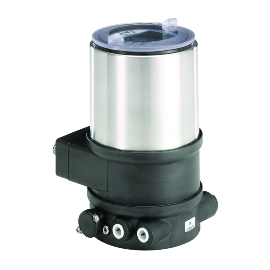
Page 8: Functions
Functions Transparent cap (below control module with display and keys) Type 8692 — Positioner (position controller) The position of the actuator (stroke) is regulated according to the Housing jacket position set-point value. The position set-point value can be specified by an external standard signal (or via field bus).
-
Page 9: Technical Data
6.1 Conformity Degree of protection Types 8692/8693 conform to the EC directives according to the EC Declaration of Conformity. Evaluated by the manufacturer: Evaluated by UL: IP65 / IP67 according to EN 60529 * UL Type 4x Rating * 6.2…
-
Page 10: Mechanical Data
Type 8692, 8693 Technicaldata 6.5.1 UL additional label Oil content Quality class X: max. 25 mg/m3 Example: Temperature range control medium 0 … + 50 °C Degree of protection Type 4X enclosure Pressure range NEC Class 2 only Circuit with limited power control medium 3 …
-
Page 11: Electrical Data
Type 8692, 8693 Technicaldata 6.8 Electrical data Input data for set-point value signal 180 Ω 0/4 … 20 mA: Input resistance WARNING! Resolution 12 bit Only circuits with limited power may be used for UL approved 0 … 5/10 V: Input resistance 19 kΩ…
-
Page 12: Operation
Designation for the function Symbol for the AUTOMATIC operating state of the keys Other symbols are displayed according to the activated functions. Operating elements: See operating instructions type 8692/8693 For description see «Fig. 5» Abbreviated designation for the displayed process value Fig. 6:…
-
Page 13: Function Of The Keys
Type 8692, 8693 Operation 7.2 Function of the keys Function of the keys on the setting level: The function of the 4 keys in the control field differs depending Function of the Description of the function on the operating state (AUTOMATIC or MANUAL) and keys operating level (process level or setting level). Arrow key Scroll up in the menus The function of the keys is displayed in the gray text field which is above the key.
-
Page 14: Operating States
Type 8692, 8693 Operatingstates OPERATING STATES 8.2 Displays in the AUTOMATIC operating state Type 8692/8693 has 2 operating states: AUTOMATIC and MANUAL. Type 8692 Description of the display Type 8693 AUTOMATIC Actual position of the valve In the AUTOMATIC operating state normal actuator (0 … 100%) controlled operation is implemented. MENU CMD MANU…
-
Page 15: Master Code
Type 8692, 8693 Operatingstates Type 8692 Description of the display Type 8693 Type 8692 Description of the display Type 8693 Automatic linearization of the P.LIN Graphical display of SP and PV process characteristics with time axis MENU SP / PV (t) HOLD MENU P.TUNE CMD/POS Simultaneous display of the Graphical display of POS…
-
Page 16: Operating Levels
Only for positioners and process controllers without There is the process level and the setting level for the operation and pre-assembled process valve. setting of type 8692/8693. Process level: 10.1 Installation of devices for the Ex area The running process is displayed and operated on this level.
-
Page 17: Installation On Process Valves, Types 2103, 2300 And 2301
1. Align the pilot air ports of the actuator with the the process valve. connection pieces of Type 8692/8693 (see «Fig. 8»). The installation of the switch spindle and the form seal is described in the operating instructions for Type 8692/8693.
-
Page 18: Installation On Process Valves, Series 26Xx And 27Xx
Attach Type 8692/8693 to the actuator using the two side fas- → tening screws. In doing so, tighten the screws only hand-tight Press Type 8692/8693 all the way down as far as the actuator and (max. tightening torque: 1.5 Nm). turn it into the required position.
-
Page 19
→ Attach Type 8692/8693 to the actuator using the two side fas- tening screws. In doing so, tighten the screws only hand-tight «In rest position» means that the pilot valves of Type 8692/ (max. -
Page 20: Pneumatic Connection
Type 8692, 8693 Installation 10.5 Pneumatic connection Control function Pneumatic connection Type 8692, 8693 with actuator DANGER! Pilot air Pilot air port actuator Risk of injury from high pressure in the system/device. outlet ▶ Before working on the system or device, switch off the pressure Types 8692 and vent/drain lines. and 8693 lower pilot air port of the Process valve Observe the following for the proper functioning of the actuator closed in rest…
-
Page 21: Electrical Installation
Type 8692, 8693 Electricalinstallation 11 ELECTRICAL INSTALLATION Exhaust air There are 2 connection options for Type 8692/8693: port • Multi-pole with circular plug-in connector Label: 3 • Cable gland with connection terminals Pilot air port Label: 1 Signal values Operating voltage: 24 V DC…
-
Page 22: Electrical Installation With Circular Plug-In Connector
In designs with proximity switch: Option: proximity switch Set the proximity switch (see «11.2.1 Setting the proximity switch — optional») Switch When the operating voltage is applied, Type 8692/8693 is (to operate loosen the screw operating. connection) → Now make the required basic settings and adjustments for the Fig.
-
Page 23
* The indicated colors refer to the connection cable available as an ** Can be adjusted via software (see operating instructions accessory (918038). Type 8692/8693 «Setting the input signal»). Tab. 4: X6 — M12 circular connector, 4-pole (operating voltage) Tab. 5:… -
Page 24
Fig. 14: Removing housing jacket and electronics module. and secure to prevent reactivation! ▶ Observe applicable accident prevention and safety regulations for electrical equipment! 1. Removing housing jacket and electronics module: → Disconnect operating voltage at Type 8692/8693 and prox- imity switch connector. English… -
Page 25
A and I → bottom end position ▶ Never adjust the proximity switch while the process is running! B → top end position → Connect operating voltage at Type 8692/8693 and proximity Jumper set switch connector. → Move actuator to the bottom end position. -
Page 26
Fig. 16: Position seal housing jacket ▶ Never adjust the proximity switch while the process is running! NOTE! → Connect operating voltage at Type 8692/8693 and proximity Breakage of the pneumatic connection pieces due to switch connector. rotational impact! → Move valve to the top end position (for control function A and I) ▶… -
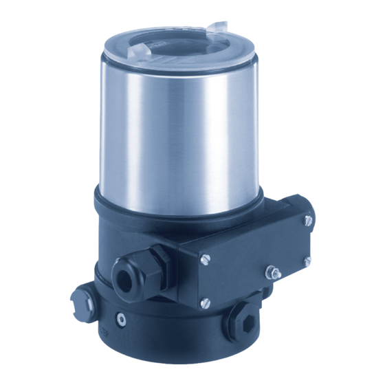
Page 27: Electrical Installation With Cable Gland
▶ Only screw on connection cover with the seal inserted. Binary output 1 Tightening torque max. 0.7 Nm. Binary output GND When the operating voltage is applied, Type 8692/8693 is operating. Binary output 2 → Now make the required basic settings and adjustments for the Tab.
-
Page 28: Electrical Installation Of Fluid Quantity Controller Type 8750
Profibus DP»). Process actual 3 (GND) → * Can be adjusted via software (see operating instructions Type 8692/8693 Connect setscrew to a suitable grounding point. To ensure «Setting the input signal»). electromagnetic compatibility (EMC), ensure that the cable is as Tab.
-
Page 29
Type 8692, 8693 Electricalinstallation Designation of the circular plug-in connectors — PROFIBUS DP: Designation of the circular plug-in connectors — DeviceNet: X3 — M12 circular connector, X2 — M12 socket, 5-pole 5-pole (inversely coded) DeviceNet (PROFIBUS DP) X5 — M8 circular connector, X5 — M8 circular connector, 4-pole (only Type 8693) 4-pole (only Type 8693) Input signals Input signals Process actual value Process actual value X6 — M12 circular connector, X6 — M12 circular connector, 4-pole 4-pole Operating voltage Operating voltage Earthing screw (TE) Earthing screw (TE) -
Page 30
The indicated colors refer to the connection cable available as an accessory (92903474). ** Can be adjusted via software (see operating instructions Type 8692/8693 «Setting up the process controller»). Tab. 11: X5 — M8 circular connector, 4-pole (process actual value) — Type 8693… -
Page 31: Start-Up
Improper operation may result in injuries as well as damage to the device and the area around it. In general, Type 8692/8693 is supplied with a pre- ▶ Before start-up, ensure that the operating personnel are familiar assembled process valve. In this case the operating mode with and completely understand the contents of the operating of the actuator is already pre-set.
-
Page 32
• Adjustment of the sensor signal to the (physical) stroke of the actuator used. 0-10 V • Determination of parameters of the PWM signals to control the 0-5 V solenoid valves integrated in type 8692/8693. EXIT Fig. 20: Operating structure INPUT; setting the input signal English… -
Page 33: Starting-Up Type 8693
Type 8692, 8693 Start-up 13.3 Starting-up Type 8693 • Setting of the controller parameters of the positioner. Optimization occurs according to the criteria of the shortest possible transient To operate the positioner as a process controller, implement the fol- time with simultaneous freedom from overshoot.
-
Page 34
Tab. 14: Basic settings of the process controller P.CO-INIT EXIT activated under SP INPUT. The parameter settings can be created automatically with the help of the P.TUNE function (description see «operating instruc- Fig. 21: Operating structure — basic settings for process controller tions for Type 8692/8693»). English… -
Page 35: Safety End Positions
Type 8692, 8693 Safetyendpositions 13.3.2 Manually changing the process 14 SAFETY END POSITIONS set-point value Safety end positions after failure Procedure: Actuator Desig- of the auxiliary power 1. S et the set-point value default on the setting level: system nation electrical pneumatic In the main menu (MAIN), select the P.CONTROL function control system for high ENTER SETUP ENTER P.CONTROL SP-INPUT internal air flow rate (DN 2,5):…
-
Page 36: Disassembly Of Type 8692/8693
▶ Following disassembly, ensure a controlled restart. Sequence: Pneumatic 1. Remove the pneumatic connections. connections 2. Disconnect the electrical connection. 3. Remove Type 8692/8693. Valve actuator Type 8692/8693 with Type 8692/8693 with process valve process valve Type 2103, 2300 or 2301 of series 26xx or 27xx Fig.
-
Page 37: Disconnecting Electrical Connections
Fastening screws Connection with Connection with circular connection terminals plug-in connector Fastening screws Type 8692/8693 with Type 8692/8693 with process valve Type 2103, process valve of series 2300 or 2301 26xx or 27xx Cable gland Connection coverl Electrical connection Fig.
-
Page 38: Accessories
Type 8692, 8693 Accessories 16 ACCESSORIES 17 TRANSPORT, STORAGE, DISPOSAL Designation Order no. NOTE! Connection cable with M12 socket, 8-pole, (length 2 m) 919061 Transport damage! Connection cable with M12 socket, 4-pole, (length 5 m) 918038 Inadequately protected devices may be damaged during Connection cable with M8 circular connector, 4-pole, transportation.
-
Page 39
12.1 Elektrische Installation …………66 Elektrische Daten …………..47 13 INBETRIEBNAHME ………………. 68 7 BEDIENUNG ………………..48 13.1 Sicherheitshinweise …………..68 Beschreibung der Bedien- und Anzeigeelemente …48 13.2 Inbetriebnahme Typ 8692 ………….69 Funktion der Tasten …………..49 13.3 Inbetriebnahme Typ 8693 …………71 deutsch… -
Page 40: Der Quickstart
15 DEMONTAGE DES TYPS 8692/8693 ……….73 Hinweise für den Gebrauch des Geräts. Die ausführliche Beschreibung 15.1 Pneumatische Verbindungen trennen ………74 finden Sie in der Bedienungsanleitung für den Typ 8692/8693. 15.2 Elektrische Verbindungen trennen……..74 Bewahren Sie den Quickstart so auf, dass er für jeden Benutzer gut 15.3 Typ 8692/8693 abmontieren ……….75…
-
Page 41: Darstellungsmittel
Das Gerät ist für den Anbau an pneumatische Antriebe von Pro- WARNUNG! zessventilen zur Steuerung von Medien konzipiert. ▶ Im explosionsgefährdeten Bereich darf der Typ 8692 und 8693 Warnt vor einer möglicherweise gefährlichen Situation! nur entsprechend der Spezifikation auf dem separaten Ex-Typ- ▶ Bei Nichtbeachtung drohen schwere Verletzungen oder Tod.
-
Page 42: Beschränkungen
Transport, sachgemäße Lagerung und Instal- lation sowie sorgfältige Bedienung und Instandhaltung. Diese Sicherheitshinweise berücksichtigen keine ▶ Setzen Sie den Typ 8692 und 8693 nur bestimmungsgemäß • Zufälligkeiten und Ereignisse, die bei Montage, Betrieb und Wartung ein. der Geräte auftreten können.
-
Page 43: Allgemeine Hinweise
Personen oder Gegenständen Voraussetzung für die Gewährleistung ist der bestimmungsgemäße gefährdet diese Bauelemente. Im schlimmsten Fall werden sie Gebrauch des Typs 8692/8693 unter Beachtung der spezifizierten sofort zerstört oder fallen nach der Inbetriebnahme aus. Einsatzbedingungen. • Die Anforderungen nach DIN EN 61340-5-1 beachten, um die Möglichkeit eines Schadens durch schlagartige, elektrostatische…
-
Page 44: Systembeschreibung
Ventilgehäuse (Beschriftung: 3) Steuerluftanschluss (Beschriftung: 1) Bild 1: Aufbau, Typ 8692/8693 mit Prozessventil Der Positioner Typ 8692 und der Prozessregler Typ 8693 sind elektro- Elektrisches Anschlussgehäuse pneumatische Stellungsregler für pneumatisch betätigte Stellventile (Anschlussvariante mit mit einfach- oder doppeltwirkenden Antrieben. Anschlussklemmen) Der Positioner und der Prozessregler bildet mit dem pneumatischen Antrieb eine optische und funktionelle Einheit.
-
Page 45: Funktionen
5.1 Funktionen TECHNISCHE DATEN 6.1 Konformität Typ 8692 — Positioner (Stellungsregler) Der Typ 8692/8693 ist konform zu den EG-Richtlinien entsprechend Die Stellung des Antriebs (Hub) wird entsprechend des Stellungs- der EG-Konformitätserklärung. Sollwerts geregelt. Der Stellungs-Sollwert kann durch ein externes 6.2 Normen Normsignal vorgegeben werden (bzw.
-
Page 46: Typschild
Typ 8692, 8693 TechnischeDaten 6.5.1 UL-Zusatzschild Umgebungstemperatur der zulässige Temperaturbereich ist auf dem Typschild des Geräts angegeben. Beispiel: Schutzart Schutzart Type 4X enclosure NEC Class 2 only Vom Hersteller bewertet: Von UL bewertet: Stromkreis mit begrenzter Leistung IP65 / IP67 nach EN 60529 *…
-
Page 47: Elektrische Daten
Typ 8692, 8693 TechnischeDaten 6.8 Elektrische Daten Ölgehalt Qualitätsklasse X, max. 25 mg/m³ Temperaturbereich WARNUNG! Steuermedium 0 … + 50 °C Bei UL zugelassenen Komponenten dürfen nur Stromkreise Druckbereich begrenzter Leistung nach „NEC Class 2“ verwendet werden. Steuermedium 3 … 7 bar…
-
Page 48: Bedienung
Symbol für den Betriebszustand AUTOMATIK 0 … 560 Ω Bürde (Last) Weitere Symbole werden entsprechend der aktivierten Funktionen (für Stromausgang 0/4 … 20 mA) angezeigt. Siehe Bedienungsanleitung Typ 8692/8693 Induktive Näherungsschalter 100 mA Strombegrenzung Kurzbezeichnung für den ange- zeigten Prozesswert Binärausgänge…
-
Page 49: Funktion Der Tasten
AUTO MENU HAND taste stand AUTOMATIK * Welche Prozesswerte im Betriebszustand AUTOMATIK angezeigt werden können ist typenabhängig. Wechsel in den Betriebszu- HAND MENU AUTOMATIK Eine detaillierte Beschreibung dazu, finden Sie in der Bedienungs- stand HAND anleitung für Typ 8692/8693. deutsch…
-
Page 50: Betriebszustände
Typ 8692, 8693 Betriebszustände BETRIEBSZUSTÄNDE Funktion der Tasten in der Einstellebene: Funktion der Der Typ 8692/8693 verfügt über 2 Betriebszustände: Taste Beschreibung der Funktion Tasten AUTOMATIK und HAND. Pfeiltaste Blättern in den Menüs nach oben AUTOMATIK Im Betriebszustand AUTOMATIK wird Vergrößern von Zahlenwerten MENU der normale Regelbetrieb ausgeführt.
-
Page 51: Anzeigen Im Betriebszustand Automatik
Sollposition (0 … 5/10 V / 0/4 … 20 mA) TEMP TEMP MENU CLOCK CMD/POS Innentemperatur im Gehäuse Uhrzeit, Wochentag und des Typs 8692/8693 ( °C) CLOCK CLOCK 12:00 12:00 Datum MENU CMD MENU CMD CMD/POS Thu. 01 . 09 . 11 Thu. 01 . 09 . 11…
-
Page 52: Mastercode
Typ 8692, 8693 Bedienebenen BEDIENEBENEN Typ 8692 Beschreibung der Anzeige Typ 8693 Für die Bedienung und Einstellung des Typs 8692/8693 gibt es die Automatische Linearisierung P.LIN Prozessebene und die Einstellebene. der Prozesskennlinien Prozessebene: MENU P.TUNE CMD/POS In dieser Ebene wird der laufende Prozess angezeigt und bedient.
-
Page 53: Montage
10.2 Sicherheitshinweise Die Montage der Schaltspindel und der Formdichtung ist in GEFAHR! der Bedienungsanleitung für Typ 8692/8693 beschrieben. Verletzungsgefahr durch hohen Druck in Anlage/Gerät. Sie finden diese auf der Bürkert-Homepage. ▶ Vor Arbeiten an Anlage oder Gerät, den Druck abschalten und Leitungen entlüften/entleeren.
-
Page 54
Beschädigung der Platine oder Funktionsausfall! Steuerluftanschlüsse ▶ Darauf achten, dass der Puck plan auf der Führungsschiene aufliegt. → Den Typ 8692/8693 ohne Drehbewegung soweit auf den Antrieb Bild 8: Ausrichten der Steuerluftanschlüsse schieben, dass an der Formdichtung kein Spalt mehr sichtbar ist. HINWEIS! 2. Den Puck des Antriebs zur Führungsschiene des Typs 8692/8693 (siehe „Bild 9“) -
Page 55: Montage An Prozessventile Der Reihe 26Xx Und 27Xx
Typ 8692/8693 beschrieben. Sie finden diese übereinander liegen (siehe „Bild 11“). auf der Bürkert-Homepage. HINWEIS! → Den Typ 8692/8693 auf den Antrieb platzieren. Dabei den Puck Zur Sicherstellung der Schutzart IP65 /IP67 die Befesti- des Antriebs passend zur Führungsschiene des Typ 8692/8693 gungsschrauben nicht zu stark anziehen. ausrichten (siehe „Bild 10“).
-
Page 56
Steuerluftanschluss des Antriebs des Antriebs in Ruhestellung hergestellt werden. oberer Steuerluftanschluss geschlossen Dadurch wird die Federkammer des Antriebs mit trockener des Antriebs Luft aus dem Entlüftungskanal des Typs 8692/8693 versorgt. oberer Steuerluftanschluss Prozessventil des Antriebs in Ruhestellung unterer Steuerluftanschluss offen des Antriebs Tab. -
Page 57: Pneumatischer Anschluss
Typ 8692, 8693 Montage 10.5 Pneumatischer Anschluss GEFAHR! Verletzungsgefahr durch hohen Druck in Anlage/Gerät. Abluftanschluss ▶ Vor Arbeiten an Anlage oder Gerät, den Druck abschalten und Beschriftung: 3 Leitungen entlüften/entleeren. Steuerluftanschluss Für die einwandfreie Funktion des Geräts beachten: Beschriftung: 1 ▶ Durch die Installation darf sich kein Rückdruck aufbauen. Zusätzlicher ▶ Für den Anschluss einen Schlauch mit ausreichendem Abluftanschluss Querschnitt wählen.
-
Page 58: Elektrische Installation 24 V Dc
Den Typ 8692/8693 entsprechend den Tabellen anschließen. Bei Ausführung mit Initiator: 11.1 Sicherheitshinweise Initiator einstellen (siehe „11.2.1 Einstellen des Initiators — Option“) GEFAHR! Nach Anlegen der Betriebsspannung ist der Typ 8692/8693 in Betrieb. Verletzungsgefahr durch elektrische Spannung! → Nun die erforderlichen Grundeinstellungen und Anpassungen für ▶…
-
Page 59
Typ 8692, 8693 ElektrischeInstallation24VDC Bezeichung der Rundsteckverbinder: X1 — Rundstecker M12, 8-polig Pin Aderfarbe* Belegung X1 — Rundstecker M12, 8-polig Eingangssignale der Leitstelle (z. B. SPS) Eingangssignale der Leitstelle Sollwert + (0/4 … 20 mA / 0 … 5/10 V) Ausgangssignale der Leitstelle blau Sollwert GND (optional) weiß Binäreingang + Ausgangssignale zur Leitstelle (z. B. SPS) — (nur bei Option X5 — Rundstecker M8, 4-polig Analogausgang und/oder Binärausgang erforderlich) (nur Typ 8693) rosa Analoge Stellungsrückmeldung +… -
Page 60
Die angegebenen Farben beziehen sich auf das als Zubehör erhältliche 1. Gehäusemantel und Elektronikmodul demontieren: Anschlusskabel (92903474). → Betriebsspannung am Typ 8692/8693 und Initiatorstecker ** Über Software einstellbar (siehe Bedienungsanleitung Typ 8692/8693 abschalten. „Einstellung des Eingangssignals“). Tab. 5: X5 — Rundstecker M8, 4-polig (Prozess-Istwert) — Typ 8693… -
Page 61
Typ 8692, 8693 ElektrischeInstallation24VDC 2. Einstellen des Initiators HINWEIS! Bruch der pneumatischen Verbindungsstutzen durch Der Initiator kann auf die untere oder obere Endstellung Dreheinwirkung! eingestellt werden. Die Handhabung zur Einstellung ist für die Steuerfunktionen unterschiedlich. ▶ Zum Abschrauben des Gehäusemantels nicht am Antrieb sondern am darüberliegenden elektrischen Anschlussgehäuse Stellschraube gegenhalten. -
Page 62
→ Steuerluft anschließen. ▶ Den Initiator nie bei laufendem Prozess einstellen! WARNUNG! → Betriebsspannung am Typ 8692/8693 und Initiatorstecker einschalten. Ventilbewegung nach Anlegen der elektrische Spannung! → Ventil in obere Endstellung (für Steuerfunktion A und I) bzw. Nach Anlegen der elektrischen Spannung fährt der Antrieb in die untere Endstellung (für Steuerfunktion B) bringen. -
Page 63
→ Elektronikmodul vorsichtig aufsetzen und gleichmäßig herunter- Betriebsspannung am Gerät und Initiatorstecker einschalten. → drücken bis die Halterungen einrasten. Typ 8692/8693 wieder in Betrieb nehmen. → Die korrekte Position der Dichtung am Gehäusemantel prüfen. Dichtung Gehäusemantel Bild 16: Position Dichtung Gehäusemantel… -
Page 64: Elektrische Installation Mit Kabelverschraubung
Anziehdrehmoment abhängig von Kabelgröße oder Blindstopfen Analoge Stellungsrückmeldung GND ca. 1,5 Nm. Binärausgang 1 ▶ Anschlussdeckel nur bei eingelegter Dichtung anschrauben. Binärausgang GND Anziehdrehmoment maximal 0,7 Nm. Binärausgang 2 Nach Anlegen der Betriebsspannung ist der Typ 8692/8693 in Tab. 7: Anschluss Kabelverschraubung Betrieb. deutsch…
-
Page 65: Elektrische Installation Für Fluidmengenregler Typ 8750
Schalter Hinweis) Prozess-Ist 2 (Kompensation) rechts Prozess-Ist 3 (GND) * Über Software einstellbar (siehe Bedienungsanleitung Typ 8692/8693 „Einrichten des Prozessreglers“). Tab. 8: Prozess-Istwert — Typ 8693 ** Den Sensor Pt 100, zur Kompensation des Leitungs- widerstands, über 3 Leitungen anschließen.
-
Page 66: Rofibus Dp / Devicenet
Zur Gewährleistung der elektromagnetischen Verträg- (zur Bedienung Verschraubung lösen) lichkeit (EMV) darauf achten, dass das Kabel möglichst kurz ist (max. 30 cm, Ø 1,5 mm Bild 18: Elektrischer Anschluss Profibus DP Nach Anlegen der Betriebsspannung ist der Typ 8692/8693 in X2 — Buchse M12, 5-polig (Bus-Anschluss) Betrieb. Signal →…
-
Page 67
Schirm Die angegebenen Farben beziehen sich auf das als Zubehör erhältliche Anschlusskabel (92903474). CAN H ** Über Software einstellbar (siehe Bedienungsanleitung Typ 8692/8693 CAN L „Einrichten des Prozessreglers“).. Tab. 11: X5 — Rundstecker M8, 4-polig (Prozess-Istwert) — Typ 8693 Tab. 10: X3 — Rundstecker M12, 5-polig (Bus-Anschluss — DeviceNet) -
Page 68: Inbetriebnahme
24 V DC Bedienung finden Sie auf unserer Homepage in der Bedie- blau Betriebsspannung nungsanleitung von Typ 8692/8693. * Die angegebenen Farben beziehen sich auf das als Zubehör erhältliche Anschlusskabel (918038). X6 — Rundstecker M12, 4-polig (Betriebsspannung) *** Den Sensor Pt 100, zur Kompensation des Leitungs- widerstands, über 3 Leitungen anschließen.
-
Page 69: Inbetriebnahme Typ 8692
Menü ACTUATOR , ist in der Bedienungsanleitung des Typs 8692/8693 beschrieben. Auswahl des Eingangssignals SELEC In der Regel wird der Typ 8692/8693 mit vormontiertem 4-20 mA Prozessventil ausgeliefert, dabei ist die Funktionsweise des Antriebs bereits eingestellt. 0-20 mA Die Eingabe der Steuerfunktion (A, B oder I) ist bei vormon- tiertem Prozessventil daher nicht erforderlich.
-
Page 70
Daten in dem EXIT verwendeten Stellgliedes. Speicher (EEPROM) abgelegt. Während des Speichervor- • Ermittlung von Parametern der PWM-Signale zur Ansteuerung der gangs erscheint das Speichersymbol auf dem Display. im Typ 8692/8693 integrierten Magnetventile. „TUNE err/break“ bei Auftreten eines Fehlers. deutsch… -
Page 71: Inbetriebnahme Typ 8693
Typ 8692, 8693 Inbetriebnahme 13.3 Inbetriebnahme Typ 8693 13.3.1 Grundeinstellungen des Prozessreglers Um den Positioner als Prozessregler betreiben zu können, führen Sie → folgende Schritte aus: Im Hauptmenü (MAIN) die Funktion P.CONTROL auswählen und die Grundeinstellungen vornehmen. 1. E inrichten des Positioners (Stellungsreglers): Beschreibung siehe „13.2.1 Festlegen der Grundeinstellungen“…
-
Page 72
Betriebszustand AUTOMATIK und HAND Wechsel um eine Stelle nach links Rückkehr Tab. 14: Grundeinstellungen des Prozessreglers ohne Eine automatische Parametereinstellung kann mit Hilfe der Änderung Ziffer erhöhen Funktion P.TUNE erfolgen (Beschreibung siehe „Bedienungs- anleitung für Typ 8692/8693“). Bild 22: Eingabe von Werten deutsch… -
Page 73: Sicherheitsendlagen
Reihenfolge: Stellsystem mit großer 1. Pneumatische Verbindungen demontieren. Luftleistung (DN 2,5): einfach- 2. Elektrische Verbindung trennen. wirkend 3. Typ 8692/8693 abmontieren. Steuer- Stellsystem mit kleiner funktion B Luftleistung (DN 0,6): down nicht definiert down / up doppelt-…
-
Page 74: Pneumatische Verbindungen Trennen
Typ 8692, 8693 DemontagedesTyps8692/8693 15.1 Pneumatische Verbindungen 15.2 Elektrische Verbindungen trennen trennen GEFAHR! GEFAHR! Verletzungsgefahr durch elektrische Spannung! Verletzungsgefahr durch hohen Druck! ▶ Vor Eingriffen in das Gerät oder in die Anlage die Spannung abschalten und vor Wiedereinschalten sichern! ▶ Vor dem Lösen von Leitungen und Ventilen den Druck ▶…
-
Page 75: Typ 8692/8693 Abmontieren
Typ 8692, 8693 Zubehör 15.3 Typ 8692/8693 abmontieren 16 ZUBEHÖR Bezeichnung Bestell-Nr. Typ 8692/8693 Anschlusskabel mit Buchse M12, 8-polig, 919061 (Länge 2 m) Befestigungschrauben Anschlusskabel mit Buchse M12, 4-polig, 918038 (Länge 5 m) Anschlusskabel mit Rundstecker M8, 4-polig, Befestigungs- 92903475 (Länge 5 m) schrauben Anschlusskabel mit Buchse M8, 4-polig, (Länge…
-
Page 76: Kommunikationssoftware
Typ 8692, 8693 Transport,Lagerung,Entsorgung 16.1 Kommunikationssoftware 17 TRANSPORT, LAGERUNG, ENTSORGUNG Das PC-Bedienungsprogramm „Communicator“ ist für die Kommu- nikation mit Geräten aus der Positioner-Familie der Firma Bürkert HINWEIS! konzipiert (ab Seriennummer 20000). Transportschäden! Eine detaillierte Beschreibung zur Installation und Bedienung der Unzureichend geschützte Geräte können durch den Transport Software finden Sie in der zugehörigen Bedienungsanleitung.
-
Page 77
Types 8692, 8693 Sommaire 1 À PROPOS DU QUICKSTART …………. 79 8 ÉTATS DE MARCHE …………….. 89 Définition du terme appareil ……….79 Changement d’état de marche ……….89 Symboles ……………….79 Affichages dans l’état de marche AUTOMATIQUE … 89 Mastercode …………….90 2 UTILISATION CONFORME …………..80 9 NIVEAUX DE COMMANDE …………..91 Limitations ……………..80 Passage entre les niveaux de commande ……91… -
Page 78
Types 8692, 8693 13 MISE EN SERVICE …………….. 107 13.1 Consignes de sécurité …………107 13.2 Mise en service du type 8692 ……….. 108 13.3 Mise en service du type 8693 ………. 110 14 POSITIONS FINALE DE SÉCURITÉ ……….112 15 DÉMONTAGE DU TYPE 8692/8693 ……….112 15.1 Couper les raccordements pneumatiques….. 113 15.2 Couper les connexions électriques …….. -
Page 79: À Propos Du Quickstart
Les moyens de représentation suivants sont utilisés dans les pré- sentes instructions. plus importantes relatives à l’utilisation de l’appareil. Vous trouverez la description détaillée dans le manuel d’utilisation du type 8692/8693. DANGER ! Conservez ce Quickstart de sorte qu’il soit accessible à tout utilisateur et à…
-
Page 80: Utilisation Conforme
L’utilisation non conforme du positionneur de type 8692 et utilisation et une maintenance parfaites. du régulateur de process de type 8693 peut présenter des ▶ Veillez à ce que l’utilisation des types 8692 et 8693, soit tou- dangers pour les personnes, les installations proches et jours conforme. l’environnement. L’appareil est conçu pour être monté sur les actionneurs pneuma- 2.1…
-
Page 81: Consignes De Sécurité Fondamentales
électrique de raccordement du faire respecter entre autres par le personnel chargé du montage. type 8692/8693. ▶ Ne pas alimenter le raccord d’air de pilotage du système en fluides agressifs ou inflammables ni en liquides.
-
Page 82: Indications Générales
Structure, type 8692/8693 avec vanne de process Également sur Internet sous : www.burkert.com Le positionneur type 8692 et le régulateur de process type 8693, sont des régulateurs de position électropneumatiques pour vannes de régulation à commande pneumatique avec actionneurs simple ou 4.2…
-
Page 83: Fonctions
Capot transparent (en-dessous module de commande avec écran et touches) Positionneur type 8692 (régulateur de position) La position de l’actionneur (course) est réglée selon la valeur de Enveloppe de corps consigne de la position. La valeur de consigne de la position est prescrite par un signal normalisé…
-
Page 84: Caractéristiques Techniques
Température ambiante : Respectez la plage de températures admissible indiquée sur la plaque signalé- 6.1 Conformité tique de l’appareil. Le type 8692/8693 respecte les directives CE conformément à la Degré de protection déclaration de conformité CE. Évalué par le fabricant : Évalué par UL : 6.2…
-
Page 85: Caractéristiques Mécaniques
Types 8692, 8693 Caractéristiquestechniques 6.5.1 Plaque supplémentaire UL Teneur en eau Classe de qualité 3, point de rosée maximal — 20 °C Exemple : ou minimal 10 °C sous la température de Degré de protection Type 4X enclosure service la plus basse NEC Class 2 only Circuit électrique à…
-
Page 86: Caractéristiques Électriques
Types 8692, 8693 Caractéristiquestechniques 6.8 Caractéristiques électriques Pt 100 : Plage de mesure -20 … +220 °C Résolution < 0,1 °C AVERTISSEMENT ! Courant de mesure < 1 mA Dans le cas des composants à homologation UL, seuls des circuits Données d’entrée pour le signal valeur de consigne électriques à…
-
Page 87: Commande
Désignation de la fonction Symbole pour l’état de marche AUTOMATIQUE des touches D’autres symboles sont affichés selon les fonctions activées. Éléments de commande : Voir Manuel d’utilisation, Type 8692/8693 Description voir « Fig. 5 » Abréviation pour la valeur de process affichée Fig. 6 : Éléments d’affichage du niveau de réglage…
-
Page 88: Fonction Des Touches
Types 8692, 8693 Commande 7.2 Fonction des touches Fonction des touches au niveau de réglage : Les fonctions des 4 touches du pupitre diffèrent suivant Fonction des l’état de marche (AUTOMATIQUE ou MANUEL) et le Touche Description de la fonction touches niveau de commande (niveau de process ou niveau de réglage). Les fonctions de touches actives sont affichées dans le champ de…
-
Page 89: États De Marche
Types 8692, 8693 Étatsdemarche ÉTATS DE MARCHE 8.2 Affichages dans l’état de marche AUTOMATIQUE Le Type 8692/8693 dispose de 2 états de marche : AUTOMATIQUE et MANUEL. Type 8692 Description de l’affichage Type 8693 AUTOMATIQUE Position effective de En mode AUTOMATIQUE, le fonction- l’actionneur de vanne nement normal du régulateur est exécuté.
-
Page 90: Mastercode
Types 8692, 8693 Étatsdemarche Type 8692 Description de l’affichage Type 8693 Type 8692 Description de l’affichage Type 8693 Linéarisation automatique des P.LIN Représentation graphique caractéristiques de processus de SP et PV avec axe de temps MENU P.TUNE MENU SP / PV (t) HOLD CMD/POS Affichage simultané de la Représentation graphique…
-
Page 91: Niveaux De Commande
Types 8692, 8693 Niveauxdecommande NIVEAUX DE COMMANDE 10 MONTAGE La commande et le réglage du Type 8692/8693 sont effectués au Uniquement pour le positionneur et le régulateur de process niveau de process et au niveau de réglage. sans vanne de process pré-installée. Niveau de process : Le process en cours est affiché et piloté à ce niveau de process.
-
Page 92: Montage Sur Les Vannes De Process Des Types 2103, 2300 Et 2301
8692/8693. → Aligner l’actionneur et le type 8692/8693 l’un par rapport à l’autre : Ces instructions peuvent être téléchargées sur le site 1. Les raccords d’air de pilotage de l’actionneur par rapport aux Internet de Bürkert.
-
Page 93: Montage Sur Les Vannes De Process Des Séries 26Xx Et 27Xx
Alignement des raccords d’air de pilotage → Fixer le type 8692/8693 sur l’actionneur à l’aide des deux vis de 2. Le rouleau presseur de l’actionneur par rapport au rail de fixation latérales. Ne serrer les vis que légèrement (couple de guidage du type 8692/8693 (voir «…
-
Page 94
Types 8692, 8693 Montage → Fixer le type 8692/8693 sur l’actionneur à l’aide des deux vis de Rail de guidage fixation latérales. Ne serrer les vis que légèrement (couple de serrage maximum : 1,5 Nm. Type Sortie d’air de pilotage 2 8692/… -
Page 95
Ainsi, la chambre à ressort de l’actionneur est alimentée en en position doit être raccordé au air sec à partir du canal de purge d’air du type 8692/8693. de repos raccord d’air de pilotage (par ressort) supérieur de l’actionneur… -
Page 96: Raccordement Pneumatique
Types 8692, 8693 Montage 10.5 Raccordement pneumatique DANGER ! Raccord Risque de blessures dû à la présence de haute pression dans d’évacuation d’air l’installation/l’appareil. Légende : 3 ▶ Avant d’intervenir dans l’installation ou l’appareil, couper la Raccord pression et désaérer/vider les conduites. d’air de pilotage Important pour le fonctionnement de l’appareil : Légende : 1 ▶ L’installation ne doit pas générer de contre-pression.
-
Page 97: Installation Électrique 24 V Dc
AVERTISSEMENT ! 24 V DC Risque de blessures dû à une installation non conforme ! ▶ L’installation doit être effectuée uniquement par un personnel 2 variantes de raccordement sont possibles pour le type 8692/8693 : qualifié et habilité disposant de l’outillage approprié ! • Multipôle avec connecteur rond Risque de blessures dû à la mise en marche involontaire de • Passe-câbles à vis avec bornes de raccordement l’installation et au redémarrage non contrôlé !
-
Page 98
Types 8692, 8693 Installationélectrique24VDC Désignation des connecteurs ronds : X1 — connecteur rond M12, 8 pôles Broche Couleur Affectation X1 — connecteur rond M12, du brin* 8 pôles Signaux d’entrée du poste de Signaux d’entrée du poste de commande (par ex. API) commande rouge Valeur de consigne + Signaux de sortie du poste de (0/4 … 20 mA / 0 … 5/10 V) commande (en option) -
Page 99
Les couleurs indiquées se rapportent aux câbles de raccordement disponibles en tant qu’accessoires (92903474). ** Réglable avec le logiciel (voir dans le manuel d’utilisation du type 8692/8693 « Réglage du signal d’entrée »). Tab. 5 : X5 — connecteur rond M8, 4 pôles (valeur effective de process) — type 8693 français… -
Page 100
Fig. 14 : Retirer l’enveloppe de corps et le module électronique. 1. Démonter l’enveloppe de corps et le module électronique : → Couper la tension de service au type 8692/8693 et à la prise du détecteur de proximité. REMARQUE ! Rupture des raccords de liaison pneumatiques due à la… -
Page 101
▶ Ne jamais effectuer le réglage du détecteur de proximité lorsque le process est en cours ! Cavalier fixé → Activer la tension de service au type 8692/8693 et à la prise du détecteur de proximité. → Réglage de la fonction : Amener l’actionneur en position finale inférieure. -
Page 102
▶ Ne jamais effectuer le réglage du détecteur de proximité lorsque REMARQUE ! le process est en cours ! → Activer la tension de service au type 8692/8693 et à la prise du Rupture des raccords de liaison pneumatiques due à la torsion ! détecteur de proximité. ▶ Pour l’insertion de l’enveloppe de corps, ne pas exercer de →… -
Page 103: Installation Électrique Avec Passe-Câbles À Vis
▶ Visser le couvercle de raccordement uniquement avec le joint Sortie binaire 1 inséré. Couple de serrage maximum 0,7 Nm. Sortie binaire GND Après application de la tension de service, le type 8692/8693 est Sortie binaire 2 en marche. Tab. 7 : Raccord passe-câble à…
-
Page 104: Installation Électrique Du Régulateur De Débit Fluidique Type 8750
Eff. process 2 (compensation) Eff. process 3 (GND) * Réglable avec le logiciel (voir dans le manuel d’utilisation du type 8692/8693 « Réglage du signal d’entrée »). Tab. 8 : Valeur effective de process — Type 8693 ** Pour des raisons de compensation de résistance de lignes, raccordez le capteur Pt 100 à…
-
Page 105: Rofibus Dp / Devicenet
12 P ROFIBUS DP / DEVICENET Désignation des connecteurs ronds — PROFIBUS DP : X2 — douille M12, 5 pôles Le guide de démarrage rapide décrit uniquement l’installation électrique du type 8692/8693 et la définition des réglages de base. (codage inverse) (PROFIBUS DP) Les réglages de la communication par bus à l’aide du menu BUS.COM sont décrits dans le manuel d’utilisation du type…
-
Page 106
Blindage disponibles en tant qu’accessoires (92903474). ** Réglable avec le logiciel (voir dans le manuel d’utilisation du type 8692/8693 « Réglage de régalateur de process »). CAN H CAN L Tab. 11 : X5 — connecteur rond M8, 4 pôles (valeur effective de process) — type 8693 Tab. -
Page 107: Mise En Service
Tension de service + 24 V DC type 8692/8693, disponibles sur notre site Internet. bleu Tension de service * Les couleurs indiquées se rapportent aux câbles de raccordement disponibles en tant qu’accessoires (918038).
-
Page 108: Mise En Service Du Type 8692
ACTUATOR est décrit dans le manuel d’utilisation du type 8692/8693. Sélection du signal d’entrée En règle générale, le type 8692/8693 est livré avec vanne SELEC de process pré-installée, le mode de fonctionnement de 4-20 mA l’actionneur est donc déjà configuré.
-
Page 109
(EEPROM). Pendant l’enregis- • Calcul des paramètres des signaux PWM pour la commande des trement, le symbole d’enregistrement apparaît à l’écran. électrovannes intégrées dans le Type 8692/8693. « TUNE err/break » lors de l’apparition d’un défaut. français… -
Page 110: Mise En Service Du Type 8693
Types 8692, 8693 Miseenservice 13.3 Mise en service du type 8693 13.3.1 Réglages de base du régulateur de process Pour pouvoir utiliser le positionneur en tant que régulateur de process, → il convient d’exécuter les étapes suivantes : Sélectionner dans le menu principal (MAIN) la fonction P.CONTROL et effectuer les réglages de base standard.
-
Page 111
Un paramétrage automatique du régulateur de process PID peut être effectué à l’aide de la fonction P.TUNE (description, voir le Augmenter le chiffre « Manuel d’utilisation pour le type 8692/8693 »). Fig. 22 : Saisie de valeurs français… -
Page 112: Positions Finale De Sécurité
1. Démonter les raccordements pneumatiques. système de réglage pour débit d’air élevé (DN 2. Couper la connexion électrique. 2,5) : 3. Démonter le type 8692/8693. simple effet Fonction système de réglage pour faible débit d’air (DN 0,6) : down non défini…
-
Page 113: Couper Les Raccordements Pneumatiques
Raccordements pneumatiques Actionneur de Presse- vanne étoupe Type 8692/8693 avec vanne Type 8692/8693 avec de process de type 2103, vanne de process Couvercle de Boîtier électrique 2300 ou 2301 de la série 26xx ou 27xx raccordement de raccordement Fig.
-
Page 114: Démonter Le Type 8692/8693
92903474 4 pôles, (5 m de long) Adaptateur USB pour le raccordement d’un Vis de fixation 227093 PC en liaison avec un câble de rallonge Type 8692/8693 avec vanne Type 8692/8693 avec Infos sur Communicator de process vanne de process www.buerkert.fr…
-
Page 115: Interface Usb
Types 8692, 8693 Transport,stockage,Élimination 16.2 Interface USB 17 TRANSPORT, STOCKAGE, ÉLIMINATION Le PC nécessite une interface USB pour la communication avec les positionneurs ainsi qu’un adaptateur supplémentaire avec pilote REMARQUE ! interface (voir « Tab. 16 ») Dommages dus au transport ! La transmission de données se faire selon la spécification HART.
-
Page 116
www.burkert.com…
This manual is also suitable for:
8693