- Home
- Инструкции
- Автоматика для ворот
- CAME
- VER V900E
![]() Автоматика для гаражных ворот CAME VER V900E инструкция по эксплуатации и монтажу на русском языке в формате pdf, размер файла 3.4 Mb. Используйте кнопки «Скачать инструкцию» или «Открыть в новом окне» (документ откроется в новом окне или вкладке браузера). Функция просмотра доступна при наличии плагина Adobe Acrobat в вашем браузере.
Автоматика для гаражных ворот CAME VER V900E инструкция по эксплуатации и монтажу на русском языке в формате pdf, размер файла 3.4 Mb. Используйте кнопки «Скачать инструкцию» или «Открыть в новом окне» (документ откроется в новом окне или вкладке браузера). Функция просмотра доступна при наличии плагина Adobe Acrobat в вашем браузере.
CAME VER V900E инструкция
Язык: Русский
Размер : 3.4 Mb
Формат файла: pdf
Добавлен: 08.06.2015
Руководство по установке и использованию
Предварительный просмотр
Информация, описание, технические характеристики изделия
ТЕХНИЧЕСКИЕ ХАРАКТЕРИСТИКИ
Напряжение питания: -230В, 50/60Hz;
Питание двигателя: =24В;
Макс. мощность аксессуаров: 40Вт;
Номинальная мощность : 1 30Вт ;
Макс. крутящий момент: 500Нм;
Средняя скорость: 6 м/мин;
Интенсивность использования: 50 %;
Класс защиты: IP40;
Вес: 5,7 кг .
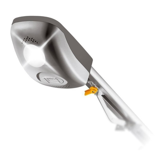
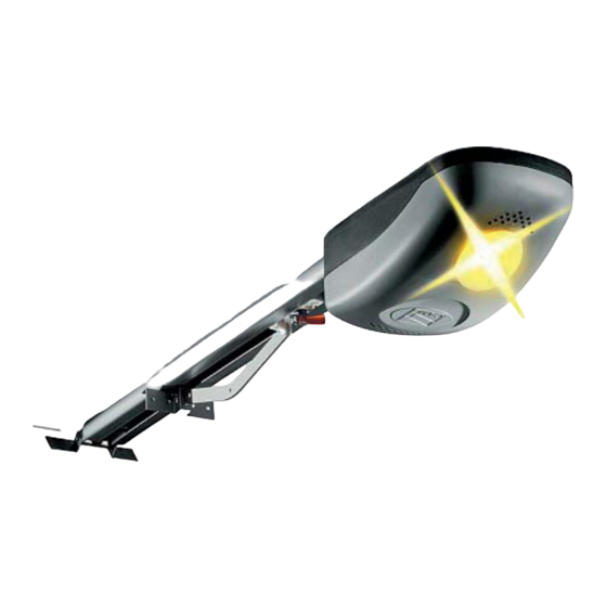
Система CAME VER V900E состоит из привода, направляющей с цепной или ременной передачей и передающего рычага. В корпусе привода из АВS-пластика находится моторедуктор, плата блока управления и сигнальная лампа. Мотаредуктор не нуждается в замене смазки. Направляющая включает в себя механизм разблокировки и кронштейн крепления передающего рычага. С одной стороны направляющей находится механизм натяжения цепи/ремня, с другой стороны ведущая звёздочка. Передающий рычаг может быть нескольких типоразмеров в зависимости от особенностей ворот.
Отзывы по оборудованию и комментарии к материалу
Здесь можно оставить свои отзывы по оборудованию «CAME VER V900E — Гаражные ворота», а также написать комментарии к материалу.
-
Contents
-
Table of Contents
-
Bookmarks
Quick Links
OVERHEAD GARAGE DOORS
VER
SERIES
INSTALLATION MANUAL
V900E
Related Manuals for CAME V900E
Summary of Contents for CAME V900E
- Page 1
AUTOMATION FOR SECTIONAL AND OVERHEAD GARAGE DOORS SERIES INSTALLATION MANUAL V900E… - Page 2
2.1 Intended use The V900E automated kit is designed to power sectional and overhead doors installed in condominiums and residential homes. The use of this product for purposes other than as described above and installation executed in a manner other than as instructed in this technical manual are prohibited. - Page 3
2) 001V0670 – Emergency battery start-up card, houses 2 (12V-1,2Ah not included) batteries ; Important! Check that the safety equipment and accessories are CAME originals; this is a guarantee that also makes the system easy to set up and upkeep. - Page 4
4.4 Dimensions 5 Installation The installation must be carried out by export, qualified personnel in total compliance with the norms in effect. 5.1 Preliminary checks Before proceeding with the installation, it is necessary to: • Make sure the area selected for the mounting of the base and for the unit itself is hazard free; •… - Page 5
5.3 Cable list and minimum thickness Connections Type of cable Length of cable 1 < 10 m L. of cable 10 < 20 m L. of cable 20 < 30 m 230V power supply 3G x 1,5 mm 3G x 2,5 mm 3G x 4 mm Flashing lamp 2 x 0,5 mm… - Page 6
5.5 Preparing the transmission guide The following applications are only examples, as the space required for unit installation and the accessories vary depending on dimensions and therefore it is up to the installer to select the best solution. 1) Fasten the bracket to the tension device on the transmission guide using the supplied bolts and washers. M6 x 20 2) Position the transmission guide in the following manner: — for sectional doors directly above spring-release coiling shaft (between 20 and 30 mm of the shaft’s axis). - Page 7
5.6 Fastening the transmission guide 1) Fasten the transmission guide to the centre of the doorway using the proper screws. Raise the guide until it is horizontal with the ceiling so as to choose the proper type of fastener. 2) If the angle brackets are not suffi cient, cut the tension brackets down to the right length and fasten them to the ceiling. N.B.: to strengthen the bar additional angle or tension brackets may be installed. - Page 8
5.7 Fastening the guide arm to the transmission guide 1) Fasten the guide arm to the top of the door frame, perpendicularly to the transmission guide. Use the supplied rivets and other suitable bolts and screws. 2) Release the traction slide by turning the small level clockwise. Move the slide towards the door and hook it onto the guide arm with the supplied bolt. - Page 9
5.8 Fastening the gearmotor to the transmission guide 1) Remove the cover of the motor unit. UNI 6954 ø 3.9 x 13 2) Fasten the motor unit to guide’s support racket using the three screws supplied with the kit. N.B.: if needed, the unit may be fasten in the other three perpendicular positions, as per the drawings. UNI 6955 ø… - Page 10
6 Electronic control panel 6.1 General description The control panel is powered by 230V on the L-N terminals, with a 50/60 Hz frequency. The command devices and accessories run on 24V. Moreover, the total accessories cannot run on more than 40W. The panel controls a service light to light up the service area;… - Page 11
6.2 Main components 1) Line fuse 1.6A 2) Emergency batteries’ slot 3) Gearmotor 4) Transformer 5) Transformer connection terminal board 6) Motor fuse 7.5A 7) Gearmotor connection terminal board Encoder connection terminal board 9) Signal Led for radio-code and encoder programming 10) Radio-code save button 11) SLOW. - Page 12
Gearmotor, encoder and transformer (only for possibile maintenance) Gearmotor Transformer 24V d.c. with encoder Command and safety devices If a button is connected, then remove the fuse-bridge. Stop button (N.C. contact) — Stops movement, excludes the automatic closing functions. To restart the automated kit, press a command button or a remote control button. Key and/or push button selector switch (N.O. - Page 13
Warning devices Movement Flasher (contact capacity: 24V – 25W max.) Flashes during the opening and closing phases. 6.4 Function selection 1 ON – Encoder programming — activates the opening and closing end-stops adjustment procedure. deactivated. Keep the dip-switch in OFF position 6.5 Adjustments Trimmer SLOW.SENS. -
Page 14: Programming The End-Stops
7 Programming the end-stops IMPORTANT: before performing any programming, read the instructions carefully. Carry out the following instructions in the proper order otherwise the programming will fail. Preliminary operations — Release the automation and position the door in the fully opened position. — When the door is fully opened, fasten the mechanical stop to the traction slide.
- Page 15
…then briefly press the ENC/RADIO button (if the signal led stays on for some seconds and then starts flashing again, the programming operation is satisfactorily complete). Programming the end-stop in the opening phase — Push and keep pressed the OPEN button until the door is fully open..then briefly press the ENC/RADIO button (if the signal led stay on the programming operations is satisfactorily complete). - Page 16
8 Activating the remote control Antenna Connect the antenna with the RG58 cable to the apposite terminals on the board. Radiofrequecy card Only for highlighted cards. Position the jumper as show in the illustration depending on the series of transmitters used (see figure). Radiofrequency Series of Frequency/MHz… - Page 17
Transmitters TOP SERIES T432M — T312M Input the code into the C selector and set the channel on D (P1 = CH1 and P2 = CH2: default setting) T432S — T432SA — T434MA — T432NA — T434NA T434M — T314M Input only the code See instructions attached P1 = CH1… - Page 18
QUARZ TOP SERIES Common coding operations for transmitters: 1 note down the selected code (for future need) 2 insert the J coding jumper to activate the procedure 3 memorise the code, pressing P1 and/or P2 in the above sequence. At the end, a double sound will confirm the memorisation. 4 remove the J jumper T262M — T302M The fi… - Page 19
T2622M — T3022M T264M — T304M 1° Code P1 = CH1 P1 = CH1 P2 = CH2 P2 = CH2 P3 = CH3 P4 = CH4 2° Code P3 = CH1 P4 = CH2 Memorisation 1) Keep the ENC/RADIO pressed on the circuit board. The led indicator will fl ash. ENC/RADIO LED flash 2) press the transmitter button to be memorised. - Page 20
UNI EN ISO 14001 standard to ensure environmental protection. Please continue our efforts to protect the environment—which CAME considers one of the cardinal elements in the development of its operational and market strategies—simply by observing brief recommendations as regards disposal: DISPOSAL OF PACKAGING –… - Page 21
Declares under its own responsibility that the equipments for automatic garage doors and gates listed below: AUTOMATION DRAW SYSTEM FOR V900E OVERHEAD AND SECTIONAL DOORS CONTAINING SOME OF THE FOLLOWING ACCESSORIES V201 — V121 — V122 — V0670 — V0679 — V0682 — V0683 — V0684… - Page 22
CAME UNITED KINGDOM LTD UNIT 3, ORCHARD BUSINESS PARK TOWN STREET, SANDIACRE NOTTINGHAM — NG10 5BP — U.K. Tel 0044 115 9210430 Fax 0044 115 9210431…
- Home
- Инструкции
- Автоматика для ворот
- CAME
- VER V900E
![]() Автоматика для гаражных ворот CAME VER V900E инструкция по эксплуатации и монтажу на русском языке в формате pdf, размер файла 3.4 Mb. Используйте кнопки «Скачать инструкцию» или «Открыть в новом окне» (документ откроется в новом окне или вкладке браузера). Функция просмотра доступна при наличии плагина Adobe Acrobat в вашем браузере.
Автоматика для гаражных ворот CAME VER V900E инструкция по эксплуатации и монтажу на русском языке в формате pdf, размер файла 3.4 Mb. Используйте кнопки «Скачать инструкцию» или «Открыть в новом окне» (документ откроется в новом окне или вкладке браузера). Функция просмотра доступна при наличии плагина Adobe Acrobat в вашем браузере.
CAME VER V900E инструкция
Язык: Русский
Размер : 3.4 Mb
Формат файла: pdf
Добавлен: 08.06.2015
Руководство по установке и использованию
Предварительный просмотр
Информация, описание, технические характеристики изделия
ТЕХНИЧЕСКИЕ ХАРАКТЕРИСТИКИ
Напряжение питания: -230В, 50/60Hz;
Питание двигателя: =24В;
Макс. мощность аксессуаров: 40Вт;
Номинальная мощность : 1 30Вт ;
Макс. крутящий момент: 500Нм;
Средняя скорость: 6 м/мин;
Интенсивность использования: 50 %;
Класс защиты: IP40;
Вес: 5,7 кг .
Система CAME VER V900E состоит из привода, направляющей с цепной или ременной передачей и передающего рычага. В корпусе привода из АВS-пластика находится моторедуктор, плата блока управления и сигнальная лампа. Мотаредуктор не нуждается в замене смазки. Направляющая включает в себя механизм разблокировки и кронштейн крепления передающего рычага. С одной стороны направляющей находится механизм натяжения цепи/ремня, с другой стороны ведущая звёздочка. Передающий рычаг может быть нескольких типоразмеров в зависимости от особенностей ворот.
Отзывы по оборудованию и комментарии к материалу
Здесь можно оставить свои отзывы по оборудованию «CAME VER V900E — Гаражные ворота», а также написать комментарии к материалу.
- Manuals
- Brands
- CAME Manuals
- Garage Door Opener
- V900E
Manuals and User Guides for CAME V900E. We have 3 CAME V900E manuals available for free PDF download: Installation Manual, Standard Installation

CAME V900E Installation Manual (105 pages)
Brand: CAME
|
Category: Gate Opener
|
Size: 10.88 MB
Table of Contents
-
Descrizione Delle Parti
5
-
Collegamenti Elettrici
13
-
Indicazioni DI Sicurezza
22
-
Manutenzione Periodica
22
-
Risoluzione Dei Problemi
23
-
Manutenzione Straordinaria
24
-
Smaltimento del Prodotto
25
-
Electrical Connections
39
-
Activating the Radiocommand
46
-
Extraordinary Maintenance
50
-
Dismantling and Disposal
51
-
Disposing of the Packaging
51
-
Description des Parties
57
-
Contrôles Préliminaires
58
-
Branchements Électriques
65
-
Indications de Sécurité
74
-
Résolution des Problèmes
75
-
Élimination de L’emballage
77
-
Дополнительные Аксессуары
83
-
Электрические Подключения
91
-
Инструкции По Безопасности
100
-
Техническое Обслуживание
100
-
Возможные Неисправности И Способы Их Устранения
101
Advertisement

CAME V900E Installation Manual (23 pages)
VER SERIES AUTOMATION FOR SECTIONAL AND OVERHEAD GARAGE DOORS
Brand: CAME
|
Category: Garage Door Opener
|
Size: 2.57 MB
Table of Contents
-
Important Safety Instructions for Installation
2
-
Destination and Limits of Use
2
-
Description of the Parts
2
-
Technical Specifications
3
-
Optional Transmission Arms
3
-
Installation Preliminary Checks
4
-
Installation Tools and Materials
4
-
Cable List and Minimum Thickness
5
-
Preparing the Transmission Guide
6
-
Fastening the Transmission Guide
7
-
Fastening the Guide Arm to the Transmission Guide
8
-
Fastening the Gearmotor to the Transmission Guide
9
-
Electronic Control Panel General Description
10
-
Electronic Control Panel Main Components
11
-
Electrical Connections
11
-
Gearmotor, Encoder and Transformer
12
-
Command and Safety Devices
12
-
Electronic Control Panel Function Selection
13
-
Electronic Control Panel Adjustments
13
-
Programming the End-Stops
14
-
Programming the End-Stop in the Closing Phase
14
-
Preliminary Operations
14
-
Programming the End-Stop in the Opening Phase
15
-
Activating the Remote Control
16
-
Demolition and Disposal
20
-
Manufacturer’s Warranty
21
CAME V900E Standard Installation (13 pages)
AUTOMATIC TRACTION SYSTEM FOR OVERHEAD AND SECTIONAL DOORS
Brand: CAME
|
Category: Garage Door Opener
|
Size: 1.64 MB
Table of Contents
-
Technical Specifications
2
-
Radio Control Installation
10
-
Manufacturer’s Declaration
12
Advertisement
Advertisement
Related Products
-
CAME VER V900E
-
CAME VER13DMS
-
CAME V6000P
-
CAME VER12
-
CAME V700
-
CAME VER10
-
CAME V1000P
-
CAME VER08DES
-
CAME VER06DES
-
CAME VER Series
CAME Categories
Gate Opener
Control Panel
Garage Door Opener
Control Unit
Control Systems
More CAME Manuals
Главная » Инструкции » Автоматика для ворот » CAME
![]()
CAME V900E — Инструкция по установке и эксплуатации (RU) в формате pdf. Руководства по установке, настройке и эксплуатации оборудования.
Дата добавления: 27.12.2017
Размер файла: 3.2 Mb
Формат файла: pdf
Просмотров: 956
Загрузок: 38
Дополнительная информация
По данному материалу пока нет информации.
Отзывы и комментарии
Отзывы и комментарии к материалу «CAME V900E — Инструкция по установке и эксплуатации (RU)».
- Manuals
- Brands
- CAME Manuals
- Garage Door Opener
- V900E
Manuals and User Guides for CAME V900E. We have 3 CAME V900E manuals available for free PDF download: Installation Manual, Standard Installation
CAME V900E Installation Manual (105 pages)
Brand: CAME
|
Category: Gate Opener
|
Size: 10.88 MB
Table of Contents
-
Descrizione Delle Parti
5
-
Collegamenti Elettrici
13
-
Indicazioni DI Sicurezza
22
-
Manutenzione Periodica
22
-
Risoluzione Dei Problemi
23
-
Manutenzione Straordinaria
24
-
Smaltimento del Prodotto
25
-
Electrical Connections
39
-
Activating the Radiocommand
46
-
Extraordinary Maintenance
50
-
Dismantling and Disposal
51
-
Disposing of the Packaging
51
-
Description des Parties
57
-
Contrôles Préliminaires
58
-
Branchements Électriques
65
-
Indications de Sécurité
74
-
Résolution des Problèmes
75
-
Élimination de L’emballage
77
-
Дополнительные Аксессуары
83
-
Электрические Подключения
91
-
Инструкции По Безопасности
100
-
Техническое Обслуживание
100
-
Возможные Неисправности И Способы Их Устранения
101
CAME V900E Installation Manual (23 pages)
VER SERIES AUTOMATION FOR SECTIONAL AND OVERHEAD GARAGE DOORS
Brand: CAME
|
Category: Garage Door Opener
|
Size: 2.57 MB
Table of Contents
-
Important Safety Instructions for Installation
2
-
Destination and Limits of Use
2
-
Description of the Parts
2
-
Technical Specifications
3
-
Optional Transmission Arms
3
-
Installation Preliminary Checks
4
-
Installation Tools and Materials
4
-
Cable List and Minimum Thickness
5
-
Preparing the Transmission Guide
6
-
Fastening the Transmission Guide
7
-
Fastening the Guide Arm to the Transmission Guide
8
-
Fastening the Gearmotor to the Transmission Guide
9
-
Electronic Control Panel General Description
10
-
Electronic Control Panel Main Components
11
-
Electrical Connections
11
-
Gearmotor, Encoder and Transformer
12
-
Command and Safety Devices
12
-
Electronic Control Panel Function Selection
13
-
Electronic Control Panel Adjustments
13
-
Programming the End-Stops
14
-
Programming the End-Stop in the Closing Phase
14
-
Preliminary Operations
14
-
Programming the End-Stop in the Opening Phase
15
-
Activating the Remote Control
16
-
Demolition and Disposal
20
-
Manufacturer’s Warranty
21
CAME V900E Standard Installation (13 pages)
AUTOMATIC TRACTION SYSTEM FOR OVERHEAD AND SECTIONAL DOORS
Brand: CAME
|
Category: Garage Door Opener
|
Size: 1.64 MB
Table of Contents
-
Technical Specifications
2
-
Radio Control Installation
10
-
Manufacturer’s Declaration
12
Related Products
-
CAME VER V900E
-
CAME VER13DMS
-
CAME V6000P
-
CAME VER12
-
CAME V700
-
CAME VER10
-
CAME V1000P
-
CAME VER08DES
-
CAME VER06DES
-
CAME VER Series
CAME Categories
Gate Opener
Control Panel
Garage Door Opener
Control Systems
Control Unit
More CAME Manuals
-
Contents
-
Table of Contents
-
Bookmarks
Quick Links
OVERHEAD GARAGE DOORS
VER
SERIES
INSTALLATION MANUAL
V900E
Related Manuals for CAME V900E
Summary of Contents for CAME V900E
-
Page 1
AUTOMATION FOR SECTIONAL AND OVERHEAD GARAGE DOORS SERIES INSTALLATION MANUAL V900E… -
Page 2
2.1 Intended use The V900E automated kit is designed to power sectional and overhead doors installed in condominiums and residential homes. The use of this product for purposes other than as described above and installation executed in a manner other than as instructed in this technical manual are prohibited. -
Page 3
2) 001V0670 – Emergency battery start-up card, houses 2 (12V-1,2Ah not included) batteries ; Important! Check that the safety equipment and accessories are CAME originals; this is a guarantee that also makes the system easy to set up and upkeep. -
Page 4
4.4 Dimensions 5 Installation The installation must be carried out by export, qualified personnel in total compliance with the norms in effect. 5.1 Preliminary checks Before proceeding with the installation, it is necessary to: • Make sure the area selected for the mounting of the base and for the unit itself is hazard free; •… -
Page 5
5.3 Cable list and minimum thickness Connections Type of cable Length of cable 1 < 10 m L. of cable 10 < 20 m L. of cable 20 < 30 m 230V power supply 3G x 1,5 mm 3G x 2,5 mm 3G x 4 mm Flashing lamp 2 x 0,5 mm… -
Page 6
5.5 Preparing the transmission guide The following applications are only examples, as the space required for unit installation and the accessories vary depending on dimensions and therefore it is up to the installer to select the best solution. 1) Fasten the bracket to the tension device on the transmission guide using the supplied bolts and washers. M6 x 20 2) Position the transmission guide in the following manner: — for sectional doors directly above spring-release coiling shaft (between 20 and 30 mm of the shaft’s axis). -
Page 7
5.6 Fastening the transmission guide 1) Fasten the transmission guide to the centre of the doorway using the proper screws. Raise the guide until it is horizontal with the ceiling so as to choose the proper type of fastener. 2) If the angle brackets are not suffi cient, cut the tension brackets down to the right length and fasten them to the ceiling. N.B.: to strengthen the bar additional angle or tension brackets may be installed. -
Page 8
5.7 Fastening the guide arm to the transmission guide 1) Fasten the guide arm to the top of the door frame, perpendicularly to the transmission guide. Use the supplied rivets and other suitable bolts and screws. 2) Release the traction slide by turning the small level clockwise. Move the slide towards the door and hook it onto the guide arm with the supplied bolt. -
Page 9
5.8 Fastening the gearmotor to the transmission guide 1) Remove the cover of the motor unit. UNI 6954 ø 3.9 x 13 2) Fasten the motor unit to guide’s support racket using the three screws supplied with the kit. N.B.: if needed, the unit may be fasten in the other three perpendicular positions, as per the drawings. UNI 6955 ø… -
Page 10
6 Electronic control panel 6.1 General description The control panel is powered by 230V on the L-N terminals, with a 50/60 Hz frequency. The command devices and accessories run on 24V. Moreover, the total accessories cannot run on more than 40W. The panel controls a service light to light up the service area;… -
Page 11
6.2 Main components 1) Line fuse 1.6A 2) Emergency batteries’ slot 3) Gearmotor 4) Transformer 5) Transformer connection terminal board 6) Motor fuse 7.5A 7) Gearmotor connection terminal boardEncoder connection terminal board 9) Signal Led for radio-code and encoder programming 10) Radio-code save button 11) SLOW.
-
Page 12
Gearmotor, encoder and transformer (only for possibile maintenance) Gearmotor Transformer 24V d.c. with encoder Command and safety devices If a button is connected, then remove the fuse-bridge. Stop button (N.C. contact) — Stops movement, excludes the automatic closing functions. To restart the automated kit, press a command button or a remote control button. Key and/or push button selector switch (N.O. -
Page 13
Warning devices Movement Flasher (contact capacity: 24V – 25W max.) Flashes during the opening and closing phases. 6.4 Function selection 1 ON – Encoder programming — activates the opening and closing end-stops adjustment procedure. deactivated. Keep the dip-switch in OFF position 6.5 Adjustments Trimmer SLOW.SENS. -
Page 14: Programming The End-Stops
7 Programming the end-stops IMPORTANT: before performing any programming, read the instructions carefully. Carry out the following instructions in the proper order otherwise the programming will fail. Preliminary operations — Release the automation and position the door in the fully opened position. — When the door is fully opened, fasten the mechanical stop to the traction slide.
-
Page 15
…then briefly press the ENC/RADIO button (if the signal led stays on for some seconds and then starts flashing again, the programming operation is satisfactorily complete). Programming the end-stop in the opening phase — Push and keep pressed the OPEN button until the door is fully open..then briefly press the ENC/RADIO button (if the signal led stay on the programming operations is satisfactorily complete). -
Page 16
8 Activating the remote control Antenna Connect the antenna with the RG58 cable to the apposite terminals on the board. Radiofrequecy card Only for highlighted cards. Position the jumper as show in the illustration depending on the series of transmitters used (see figure). Radiofrequency Series of Frequency/MHz… -
Page 17
Transmitters TOP SERIES T432M — T312M Input the code into the C selector and set the channel on D (P1 = CH1 and P2 = CH2: default setting) T432S — T432SA — T434MA — T432NA — T434NA T434M — T314M Input only the code See instructions attached P1 = CH1… -
Page 18
QUARZ TOP SERIES Common coding operations for transmitters: 1 note down the selected code (for future need) 2 insert the J coding jumper to activate the procedure 3 memorise the code, pressing P1 and/or P2 in the above sequence. At the end, a double sound will confirm the memorisation. 4 remove the J jumper T262M — T302M The fi… -
Page 19
T2622M — T3022M T264M — T304M 1° Code P1 = CH1 P1 = CH1 P2 = CH2 P2 = CH2 P3 = CH3 P4 = CH4 2° Code P3 = CH1 P4 = CH2 Memorisation 1) Keep the ENC/RADIO pressed on the circuit board. The led indicator will fl ash. ENC/RADIO LED flash 2) press the transmitter button to be memorised. -
Page 20
UNI EN ISO 14001 standard to ensure environmental protection. Please continue our efforts to protect the environment—which CAME considers one of the cardinal elements in the development of its operational and market strategies—simply by observing brief recommendations as regards disposal: DISPOSAL OF PACKAGING –… -
Page 21
Declares under its own responsibility that the equipments for automatic garage doors and gates listed below: AUTOMATION DRAW SYSTEM FOR V900E OVERHEAD AND SECTIONAL DOORS CONTAINING SOME OF THE FOLLOWING ACCESSORIES V201 — V121 — V122 — V0670 — V0679 — V0682 — V0683 — V0684… -
Page 22
CAME UNITED KINGDOM LTD UNIT 3, ORCHARD BUSINESS PARK TOWN STREET, SANDIACRE NOTTINGHAM — NG10 5BP — U.K. Tel 0044 115 9210430 Fax 0044 115 9210431…
-
#1
Уважаемые знатоки! Не могу перепрограммировать конечную точку закрытия ворот. Действую точно по инструкции. Но не получается.
Есть расхождение с инструкцией, по симптоматике.
Открытое положение выставляется, а нижнее нет.
Внимание вопрос: что делаю не так?
-

IMAG4067.jpg
3.4 MB
· Просмотры: 296
-

IMAG4068.jpg
1.8 MB
· Просмотры: 206
-

IMAG4069.jpg
2.4 MB
· Просмотры: 168
-
#2
Попробуй частичное закрывание, дип 2 поднять …
-
#3
Был похожий случай именно с этим мотором. Я пытался конечную точку «подвесить» в воздухе. Не получилось. А вот когда прижал ворота к полу как следует — сработало. У меня создалось впечатление, что привод определяет нагрузку и именно по ее возрастанию признает конечную точку. Для себя поставил ему за это жирный минус.
-
#4
Попробуй частичное закрывание, дип 2 поднять …
Дип 2=частичное открывание и замедление при закрывания.
Выставил их на 1/3 открытых ворот. Замедляться стали раньше, но точка закрытия не изменилась
А то что маячок при программировании иначе чем в инструкции себя ведёт — это не важно?
-
#5
Был похожий случай именно с этим мотором. Я пытался конечную точку «подвесить» в воздухе. Не получилось. А вот когда прижал ворота к полу как следует — сработало. У меня создалось впечатление, что привод определяет нагрузку и именно по ее возрастанию признает конечную точку. Для себя поставил ему за это жирный минус.
Именно так!!! Пока не упрётся, до хруста в траверсах/консолях не останавливается. Я хотел уменьшить нагрузку, создав «подвис» — недовод на 1-2 см. Значит нет выхода?
-
#6
Подложите подкладку при программировании — потом уберете.
-
#7
Именно так!!! Пока не упрётся, до хруста в траверсах/консолях не останавливается. Я хотел уменьшить нагрузку, создав «подвис» — недовод на 1-2 см. Значит нет выхода?
А если на штанге (по которой двигается цепь) установить упор? Или так можно вообще «голову свернуть» всей установке?
-
#8
Подложите подкладку при программировании — потом уберете.
Вы так делали? Или гипотеза?
-
#9
А если на штанге (по которой двигается цепь) установить упор? Или так можно вообще «голову свернуть» всей установке?
По инстркуции упор на открывание ставится. Но можно.
-
#10
Вы так делали? Или гипотеза?
Почему гипотеза ? Программируем с хрустом, убираем упор — и ворота зависают в воздухе. Проблема то только при запоминании. Они и з задним упором так себя ведут. При программировании — упираются, а потом тормозят заранее.
-
#11
Почему гипотеза ? Программируем с хрустом, убираем упор — и ворота зависают в воздухе. Проблема то только при запоминании. Они и з задним упором так себя ведут. При программировании — упираются, а потом тормозят заранее.
Завтра попробую. По результату сообщу…
Смущает то, что открывание программируется без упоров и каких-либо импровизаций.
-
#12
Завтра попробую. По результату сообщу…
Смущает то, что открывание программируется без упоров и каких-либо импровизаций.
Ничего не поменяется. Если хотите сместить нижнюю точку, нужен передний упор.
-
#13
Ничего не поменяется. Если хотите сместить нижнюю точку, нужен передний упор.
Признаюсь, как раз сейчас хотел попробовать (что-нибудь подложить при закрытии, но боюсь сломать редуктор). И не понимаю в сути подкладывания — ведь при программировании ворота и без всякиз приспособ выставляются на нужной точке закрытия, а вот после программирования — тутже запираются до предела.
А что значит «нужен передний упор»? Ведь положение открытых ворот программируется на любой высоте без проблем.
-
#14
Крутить SENS не пробовали при настройке? Попробуйте поставить высокую степень чувствительности или низкую, соответственно крутить по часовой стрелке для увеличения.
-
#15
Крутить SENS не пробовали при настройке? Попробуйте поставить высокую степень чувствительности или низкую, соответственно крутить по часовой стрелке для увеличения.
Его можно просто крутить, или надо один из ДИНов включать?
Нет, не пробовал. Вечером попробую (наверное — убавить?)…
Дмитрий, а то что маячок ведёт себя не «по писаному» (первое сообщение в этой теме с картинками) при программировании не имеет значения?
-
#16
Не понятна причина, по которой необходимо создать щель в несколько сантиметров. Подвесить ворота не получится без упора на закрытие (как писал MobyDick). Если нет второго упора, попробуйте подложить две дощечки под полотно, настроить, заменить на стационарные упоры. С 900-м никогда проблем не возникало. Хороший моторчик. Вопрос возник. Какие у Вас ворота (тип подъема, какие пружины)? Может не отрегулированы ролики верхней панели как положено?
-
#17
Не понятна причина, по которой необходимо создать щель в несколько сантиметров. Подвесить ворота не получится без упора на закрытие (как писал MobyDick). Если нет второго упора, попробуйте подложить две дощечки под полотно, настроить, заменить на стационарные упоры. С 900-м никогда проблем не возникало. Хороший моторчик. Вопрос возник. Какие у Вас ворота (тип подъема, какие пружины)? Может не отрегулированы ролики верхней панели как положено?
Сейчас как раз «упражняюсь» с автоматикой. Причина — штанга привода (где цепь) имеет пластиковый наконечник, который при закрывании до упора норовит сломаться. Закрывается так что уплотнитель сжимает «в ноль».
Сейчас фоты скину…
-
#18
Как вариант, удлинить тягу привода, чтобы изменить направление вектора приложения силы.
-
#19
Как вариант, удлинить тягу привода, чтобы изменить направление вектора приложения силы.
Вот это мудро! Видно по фото, что тяга при закрытых воротах стоит вертикально.
-

IMAG4146.jpg
2.6 MB
· Просмотры: 216
-
#20
Крутить SENS не пробовали при настройке? Попробуйте поставить высокую степень чувствительности или низкую, соответственно крутить по часовой стрелке для увеличения.
Полурешение есть! SLOW SENS — максимально на «+». И закрывает без фанатичного старания. Спасибо!
- Home
- Инструкции
- Автоматика для ворот
- CAME
- VER V900E
| CAME VER V900E инструкция | |
|---|---|
| Тип инструкции: | Руководство по установке и использованию |
| Категория: | Автоматика для ворот CAME |
| Язык: | Русский |
| Размер: | 3.4 Mb |
| Формат файла: | |
| Дата добавления: | 08.06.2015 |
Информация, описание, технические характеристики изделия
ТЕХНИЧЕСКИЕ ХАРАКТЕРИСТИКИ
Напряжение питания: -230В, 50/60Hz;
Питание двигателя: =24В;
Макс. мощность аксессуаров: 40Вт;
Номинальная мощность : 1 30Вт ;
Макс. крутящий момент: 500Нм;
Средняя скорость: 6 м/мин;
Интенсивность использования: 50 %;
Класс защиты: IP40;
Вес: 5,7 кг .
Система CAME VER V900E состоит из привода, направляющей с цепной или ременной передачей и передающего рычага. В корпусе привода из АВS-пластика находится моторедуктор, плата блока управления и сигнальная лампа. Мотаредуктор не нуждается в замене смазки. Направляющая включает в себя механизм разблокировки и кронштейн крепления передающего рычага. С одной стороны направляющей находится механизм натяжения цепи/ремня, с другой стороны ведущая звёздочка. Передающий рычаг может быть нескольких типоразмеров в зависимости от особенностей ворот.
Отзывы по оборудованию и комментарии к материалу
- Manuals
- Brands
- CAME Manuals
- Gate Opener
- V900E
- Installation manual
-
Contents
-
Table of Contents
-
Troubleshooting
-
Bookmarks
Quick Links
1 19E T9 7
IT
Italiano
EN
English
FR
Français
RU
Русский
AUTOMAZIONE
PER PORTE BASCULANTI E SEZIONALI
MANUALE D’INSTALLAZIONE
V900E
Related Manuals for CAME V900E
Summary of Contents for CAME V900E
-
Page 1
AUTOMAZIONE 1 19E T9 7 PER PORTE BASCULANTI E SEZIONALI Italiano English Français Русский MANUALE D’INSTALLAZIONE V900E… -
Page 2
Avvertimento (es. targa cancello). stato espressamente concepito. Ogni altro uso è da conside- Istruzioni e raccomandazioni rarsi quindi pericoloso. La CAME cancelli automatici s.p.a. non particolari per gli utenti è responsabile per eventuali danni causati da usi impropri, er- • Tenete libere da ingombri e pulite le aree di manovra del can- ronei ed irragionevoli •… -
Page 4: Legenda Simboli
— porte sezionali fi no a 3,20 m di altezza 3 Riferimenti normativi Came Cancelli Automatici è una azienda certificata per il sistema di gestione della qualità aziendale ISO 9001 e di gestione ambientale ISO 14001. Came progetta e produce interamente in Italia.
-
Page 5: Descrizione Delle Parti
4.3 Descrizione delle parti GRUPPO MOTORIDUTTORE Coperchio di protezione Motoriduttore Trasformatore Scheda elettronica ZL56 Braccio di trasmissione standard GUIDE DI SCORRIMENTO 001V0679 — Gruppo guida con catena L = 3.02 m 001V0684 — come 001V0679 ma in due pezzi da assemblare: — porte basculanti a contrappesi fi…
-
Page 6: Installazione
4.4 Dimensioni 400 mm 3020 mm min. ÷ 4020 mm max. 5 Installazione L’installazione deve essere effettuata da personale qualificato ed esperto e nel pieno rispetto delle normative vigenti. 5.1 Verifiche preliminari Prima di procedere all’installazione dell’automatismo è necessario: • Verificare che l’installazione dell’automazione non generi situazioni di pericolo; •…
-
Page 7
5.3 Tipo cavi e spessori minimi Lunghezza cavo Lunghezza cavo Lunghezza cavo Collegamento Tipo cavo 1 < 10 m 10 < 20 m 20 < 30 m Alimentazione 3G x 1,5 mm 3G x 2,5 mm 3G x 4 mm Lampeggiatore 2 x 0,5 mm 2 x 1 mm… -
Page 8
5.5 Predisposizione della guida di trasmissione Le seguenti illustrazioni sono solo esempi, in quanto lo spazio per il fissaggio dell’automazione e degli accessori varia a seconda degli ingombri. Spetta quindi all’installatore scegliere la soluzione più adatta 1) Fissare la staff a al dispositivo di tensionamento della guida di trasmissione con le viti e i dadi in dotazione. M6 x 20 2) Posizionare la guida di scorrimento nel seguente modo: — per porte sezionali sopra l’ingombro della staff a del palo-molla. -
Page 9
5.6 Fissaggio della guida di scorrimento 1) Fissare la barra di scorrimento al centro del vano porta con viti adeguate. Sollevare la barra e disporla orizzontalmente per rilevare la distanza dal soffi tto allo scopo di scegliere il tipo di fi ssaggio. 2) Se gli angolari non sono suffi cienti, tagliare i tiranti nella misura necessaria e fi… -
Page 10
5.7 Fissaggio del braccio di trasmissione alla barra di scorrimento 1) Fissare braccio di trasmissione al traverso superiore della porta perpendicolarmente alla barra di scorrimento. Utilizzare i rivetti in dotazione o altre viti adeguate. 2) Sbloccare la slitta di trascinamento girando la levetta in senso orario. Spostare la slitta verso la porta e agganciarla al braccio di trasmissione con il bullone in dotazione UNI 5739 M6 x 20… -
Page 11
5.8 Fissaggio del motoriduttore alla barra di trasmissione 1) Togliere il coperchio del contenitore del gruppo motore. UNI 6954 ø 3.9 x 13 2) Fissare il gruppo motore al supporto di sostegno della barra con le tre viti in dotazione. N.B.: se necessario, il gruppo può… -
Page 12: Descrizione Generale
6 Scheda elettronica di comando 6.1 Descrizione generale La scheda di comando va alimentata a 230 V sui morsetti L-N, frequenza 50 / 60 Hz. I dispositivi di comando e gli accessori sono a 24 V. Inoltre gli accessori non devono superare complessivamente i 40 W. La scheda controlla una lampada di servizio per illuminare la zona di manovra;…
-
Page 13: Componenti Principali
6.2 Componenti principali Fusibile di linea 1.6 A Spazio per batterie d’emergenza Motoriduttore Trasformatore Morsettiera collegamento trasformatore Fusibile motore 8 A Morsettiera collegamento motoriduttore Morsettiera collegamento encoder Led segnalazione radio e programmazione encoder 10. Pulsante di memorizzazione codice radio 11. Trimmer SLOW.SENS: regolazione della sensibilità amperometri- ca in rallentamento 12.
-
Page 14
Motoriduttore, encoder e trasformatore (solo per eventuali manutenzioni) Trasformatore Motoriduttore 24 V DC con encoder Dispositivi di comando e sicurezza Se viene collegato un dispositivo, togliere il ponticello Pulsante di stop (contatto NC) — Arresta il movimento, escludendo la chiusura automa- tica. -
Page 15
Dispositivi di segnalazione Lampeggiatore di movimento (portata contatto: 24 V — 25 W max.) — Lampeggia in fase di apertura e chiusura 6.4 Selezione funzioni 1 ON — Attiva la procedura di regolazione dei fi necorsa di apertura e di chiusura e la procedura di programmazione per la par- tenza rallentata in apertura 2 ON — Attiva la procedura di regolazione per l’apertura parziale e la procedura di programmazione per il rallentamento a fi… -
Page 16
7 Programmazione 7.1 Programmazione dei finecorsa di chiusura e apertura IMPORTANTE: prima di procedere con la programmazione dei fi necorsa, leggere attentamente le istruzioni. Seguire nell’ordine le successive istruzioni altrimenti la programmazione non avrà esito positivo 1 — Operazioni preliminari — Sbloccare l’automazione e posizionare la porta nel punto di massima apertura. -
Page 17
…quindi premere il tasto ENC/RADIO fino a quando il led di segnalazione rimane acceso per alcuni secondi e poi riprende a lam- peggiare (l’operazione di programmazione si è conclusa positivamente). 3 — Programmazione del finecorsa in apertura — Premere e tenere premuto il tasto OPEN fino a che la porta arriva al punto di massima apertura..quindi premere il tasto ENC/RADIO fino a quando il led di segnalazione rimane acceso (l’operazione di programmazione si è… -
Page 18
7.2 Programmazione per l’apertura parziale A portone completamente chiuso, posizionare il dip 2 in ON (il led di segnalazione programmazione lampeggia). Premere e tenere premuto il tasto OPEN fi no a quando il portone raggiunge il punto di apertura desiderata .. -
Page 19
Premere il tasto OP/CL fi no a quando il portone raggiunge il punto di fi ne rallentamento desiderato; premere poi il tasto ENC/RADIO fi no a quando il led di segnalazione rimane acceso (l’operazione di programmazione si è conclusa positivamente). Riportare il dip 1 in OFF. -
Page 20
8 Attivazione del radiocomando 1 — Antenna Collegare l’antenna con il cavo agli appositi morsetti sulla scheda. 2 — Scheda di radiofrequenza Innestare la scheda di radiofrequenza sulla scheda elettronica DOPO AVER TOLTO LA TENSIONE (o scollegato le batterie). N.B.: La scheda elettronica riconosce la scheda di radiofrequenza solo quando viene alimentata. Scheda radiofrequenza AF Scheda elettronica 3 — Trasmettitori… -
Page 21
4 — Memorizzazione e cancellazione utenti radio Attivazione comando sequenziale (2-7) Tenere premuto il tasto ENC/RADIO sulla scheda elettronica. Il led lampeggia. Premere il tasto (T1) del trasmettitore da memorizzare. Il led rimarrà acceso a segnalare l’avvenuta memorizzazione. ENC/RADIO LED acceso Scheda radio AF LED intermittente Attivazione comando di apertura parziale (2-3P) -
Page 22: Indicazioni Di Sicurezza
9 Indicazioni di sicurezza Importanti indicazioni generali di sicurezza Questo prodotto deve essere destinato solo all’uso per il quale è stato espressamente studiato. Ogni altro uso è da considerarsi improprio e quindi pericoloso. Il costruttore non può essere considerato responsabile per eventuali danni causati da usi impropri, erronei ed irragionevoli.
-
Page 23: Risoluzione Dei Problemi
-Per la pulizia delle fotocellule utilizzare un panno leggermente inumidito con acqua, non utilizzare solventi o altri prodotti chimici perchè potrebbero rovinare i dispositivi. -Lubrificare i punti di snodo con del grasso, ogni qual volta si manifestino vibrazioni anomale e cigolii, come rappresentato di seguito.
-
Page 24: Manutenzione Straordinaria
Registro manutenzione periodico a cura dell’utente (ogni 6 mesi) Data Annotazioni Firma 10.3 Manutenzione straordinaria La seguente tabella serve per registrare gli interventi di manutenzione straordinaria, di riparazione e di miglioramento eseguiti da ditte esterne specializzate. N.B. Gli interventi di manutezione straordinaria devono essere effettuati da tecnici specializzati. Registro manutenzione straordinaria Timbro installatore Nome operatore…
-
Page 25: Smaltimento Del Prodotto
UNI EN ISO 14001 a garanzia del rispetto e della tutela dell’ambiente. Vi chiediamo di continuare l’opera di tutela dell’ambiente, che CAME considera uno dei fondamenti di sviluppo delle proprie strate- gie operative e di mercato, semplicemente osservando brevi indicazioni in materia di smaltimento: SMALTIMENTO DELL’IMBALLO…
-
Page 26
HR • Za sve dodatne informacije o poduzeću, proizvodima i tehničkoj podršci: UK • Для отримання будь-якої іншої інформації про компанію, продукцію та технічну підтримку: www. came.com www. came.com CAME Cancelli Automatici S.p.a. CAME Cancelli Automatici S.p.a. Via Martiri Della Libertà, 15 31030 Dosson Di Casier… -
Page 27
OPERATOR 11 9E T9 7E N FOR OVERHEAD AND SECTIONAL DOORS INSTALLATION MANUAL V900E English… -
Page 28: Read Carefully
Warning Sings (e.g. gate plate). (i.e. that for which it was expressly built for). Any other use is Special instructions and to be considered dangerous. Came Cancelli Automatici S.p.A. advice for users is not liable for any damage resulting from improper, wrongful •…
-
Page 30: Legend Of Symbols
2 Intended use and limits to use 2.1 Intended use The V900E operator is engineered to power overhead and sectional doors in individual homes and apartment complexes. Any installation and use other than that specified in this manual is forbidden.
-
Page 31: Description Of Parts
4.3 Description of parts GEARMOTOR ASSEMBLY Protective cover Gearmotor Transformer ZL56 Electronic card Standard transmission arm SLIDE GUIDES 001V0679 — Guide assembly with chain L = 3.02 m 001V0684 — like the 001V0679 but in two pieces to assemble: — counterweighted overhead doors up to 2.4 m high; — spring-loaded overhead doors up to 2.25 m high;…
-
Page 32: Preliminary Checks
4.4 Dimensions 400 mm 3020 mm min. ÷ 4020 mm max. 5 Installation Installation must be carried by skilled, qualified technicians in accordance with current regulations. 5.1 Preliminary checks Before installing the operator, do the following: • Check that the installing the operator does not create and hazardous situations; Set up a suitable omnipolar cut-off device, with distances greater than 3 mm between contacts, with sectioned power source;…
-
Page 33: Application Examples
5.3 Cable types and minimum thickness Cable length Cable length Cable length Connection Cable type 1 < 10 m 10 < 20 m 20 < 30 m Power supply 3G x 1.5 mm 3G x 2.5 mm 3G x 4 mm Flashing light 2 x 0.5 mm 2 x 1 mm…
-
Page 34
5.5 Setting up the transmission guide The following illustrations are just examples, in that the space for securing the operator and accessories depends on the overall measurements. It is up to the installer to choose the most suited solution 1) Fasten the bracket to the transmission guide’s tensioning device using the issued nuts and bolts. M6 x 20 2) Position the slide guide in the following way: — for sectional doors above the footprint of the spring-post bracket. -
Page 35
5.6 Fastening to the slide rail 1) Fasten the slide bar to the centre of the door opening using suitable bolts. . Raise the bar and position it horizontally to detect the distance from the ceiling to help you choose the type of fastening. 2) If the angle-rods are not enough, cut the rods to the required length and fasten them to the ceiling. -
Page 36
5.7 Fastening the transmission arm to the slide bar 1) Fasten the transmission arm to the door’s upper crossbeam, perpendicularly to the slide bar. Use the supplied rivets or any other suitable screws. 2) Release the drag-sled by turning the small tab clockwise. Move the sled towards the door and hook it up to the transmission arm using the supplied nut. -
Page 37
5.8 Fastening the gearmotor to the transmission bar 1) Remove the motor assembly’s container cover. UNI 6954 ø 3.9 x 13 2) Fasten the motor assembly to the bar support using the three supplied screws. N.B.: if necessary, the group can be fastened in three other perpendicular positions, as shown in the drawing. UNI 6955 ø… -
Page 38: General Description
6 Electronic command card 6.1 General description The command card is 230 V powered on terminals L-N, 50 / 60 Hz frequency. the command devices and accessories are powered by 24 V. Moreover, accessories must not exceed 40 W overall. The card control a duty lamp to illuminate the driving/parking area.
-
Page 39: Main Components
6.2 Main components 1.6 A line fuse Space for emergency batteries Gearmotor Transformer Transformer connection terminals 8 A motor fuse Gearmotor connection terminals Encoder connection terminals Radio and encoder programming led signal light 10. Button to memorise the radio code 11.
-
Page 40
Gearmotor, encoder and transformer (only for possible maintenance actions) Transformer 24 V DC gearmotor with encoder Command and safety devices If any device is connected, remove the bridge. Stop button (NC contact) — Halts movement, and excluded automatic closing. To restore the operator, press a command button or a radio command button. -
Page 41: Selecting Functions
Warning devices Movement Flasher (contact rated for: 24 V — 25 W Max.) — Flashes in the opening and closing phases 6.3 Selecting functions 1 ON — It activates the opening and closing endpoint adjusting procedure and the programming procedure for starting slow- down when opening.
-
Page 42
7 Programming 7.1 Programming the closing / opening endpoints IMPORTANT: before proceeding with endpoint programming, read instructions carefully. Follow the order of the instructions below otherwise the memorisation will not work. 1- Preliminary operations — Release the operator and open the door completely. — With door fully open, fasten the mechanical stop to the drag sled. -
Page 43
… then press the ENC/RADIO button until the led signal light stays lit for some seconds and then starts to flash again (the pro- gramming procedure is successfully completed). 3 — Programming the opening endpoint — Press and keep pressed the OPEN button until the door reaches the maximum opening point … then press the ENC/RADIO button until the led signal light stays on (the programming procedure is successfully finished). -
Page 44
7.2 Programming the partial opening With door completely closed, position dip-switch 2 to ON (the led signal light will fl ash). Press and keep pressed the OPEN button until the door reaches the required opening point..then press the ENC/RADIO button until the led signal light stays on (the programming procedure is successfully finished). Set dip-switch 2 back to OFF. -
Page 45
Press the OP/CL button until the door reaches the required slow-down point; then press the ENC/RADIO button until the led signal light stays on (the programming procedure is successfully fi nished). Set dip-switch 1 back to OFF. 7.4 Programming closing slow-downs . -
Page 46: Activating The Radiocommand
8 Activating the radiocommand 1 — Antenna Connect the antenna with cable to the apposite terminals on the card. 2 — Radio-frequency card Plug in the radio-frequency card onto the electronic board AFTER CUTTING OFF THE MAIN POWER SUPPLY (or disconnecting the emergency batteries).
-
Page 47
4 — Memorising and cancelling radio users Activating the sequential (2-7) command Keep buttonENC/RADIO button pressed on the electronic card. The LED fl ashes ON and OFF. Press the (T1) button on the transmitter you want to memorise. The LED will stay ON to confi rm memorisation is OK. ENC/RADIO LED on AF radio card… -
Page 48: Safety Instructions
9 Safety instructions Important general safety instructions This product is only intended to be used for the purpose it was designed. Any other use is therefore improper and dangerous. The manufacturer is not liable for any damage caused by improper, wrongful or unreasonable use. Work well away from the gate hinges or mechanical moving parts.
-
Page 49: Troubleshooting
-To wipe clean the photocell glass, use a slightly damp cloth, and do not use any solvents or other chemical products that may ruin the device. Lubricate all joints with grease, any time strange vibrations or noises are manifested, as shown below. -Check that the photocells are free of any vegetaion blocking them, and that there are no obstacles to the free movement of the door.
-
Page 50: Extraordinary Maintenance
Periodic maintenance log to be done by users (every 6 months) Date Notes Signature 10.3 Extraordinary maintenance The following table is used to log extraordinary maintenance, repair and improvement jobs done by the specialised external firms. N.B. All extraordinary maintenance jobs must be carried out by skilled technicians. Extraordinary maintenance log Installer’s stamp Product name…
-
Page 51: Dismantling And Disposal
UNI EN ISO 14001 standard to ensure environmental protection. Please help us to safeguard the environment. At CAME we believe this to be one of the fundamentals in its market operations and development strategies. Just follow these short disposal instructions: DISPOSING OF THE PACKAGING The components of the packaging (i.e.
-
Page 52
HR • Za sve dodatne informacije o poduzeću, proizvodima i tehničkoj podršci: UK • Для отримання будь-якої іншої інформації про компанію, продукцію та технічну підтримку: www. came.com www. came.com CAME Cancelli Automatici S.p.a. CAME Cancelli Automatici S.p.a. Via Martiri Della Libertà, 15 31030 Dosson Di Casier… -
Page 53: Manuel D’installation
AUTOMATISME 11 9ET 9 7F R POUR PORTES BASCULANTES ET SECTIONNELLES MANUEL D’INSTALLATION V900E Français…
-
Page 54
été spécifi quement conçu. Tout autre usage sera • Conservez la zone de manœuvre du portail propre et sans rien donc considéré comme dangereux. La société CAME Cancelli qui risque de l’encombrer. Retirez la végétation se trouvant dans Automatici S.p.A. -
Page 56: Limites D’utilisation
— portes sectionnelles jusqu’à 3,20 m de haut 3 Références normatives Came Cancelli Automatici est une société certifiée pour le système de gestion de la qualité ISO 9001 et de gestion environnementale ISO 14001. La société Came conçoit et produit entièrement en Italie.
-
Page 57: Description Des Parties
4.3 Description des parties GROUPE MOTORÉDUCTEUR Couvercle de protection Motoréducteur Transformateur Carte électronique ZL56 Bras de transmission standard GLISSIÈRES 001V0679 — Groupe glissière avec chaîne L = 3,02 m 001V0684 — comme 001V0679 mais en deux pièces à assembler : — portes basculantes à…
-
Page 58: Contrôles Préliminaires
4.4 Dimensions 400 mm 3020 mm min. ÷ 4020 mm max. 5 Installation L’installation doit être effectuée par du personnel qualifié et dans le plein respect des normes en vigueur. 5.1 Contrôles préliminaires Avant d’installer l’automatisme, il faut : • S’assurer que l’installation de l’automatisme ne provoque aucune situation dangereuse ; •…
-
Page 59
5.3 Types de câbles et épaisseurs minimum Longueur câble Longueur câble Longueur câble Connexion Type câble 1 < 10 m 10 < 20 m 20 < 30 m Alimentation 3G x 1,5 mm 3G x 2,5 mm 3G x 4 mm Clignotant 2 x 0,5 mm 2 x 1 mm… -
Page 60
5.5 Adaptation du rail de transmission Les illustrations suivantes ne sont que des exemples étant donné que l’espace pour la fixation de l’automatisme et des accessoires varie en fonction des encombrements. C’est donc l’installateur qui doit choisir la solution la plus indiquée. 1) Fixer la bride au dispositif tendeur du rail de transmission à… -
Page 61
5.6 Fixation du rail de glissement 1) Fixer la barre de glissement au centre du logement de la porte avec des vis spécifi ques Soulever la barre et la positionner horizontalement pour détecter la distance par rapport au plafond afi n de choisir le type de fi… -
Page 62
5.7 Fixation du bras de transmission à la barre de défilement 1) Fixer le bras de transmission à la traverse supérieure de la porte, perpendiculairement à la barre de glissement. Utiliser les rivets fournis ou d’autres vis spécifi ques. 2) Débloquer le rail de guidage en tournant le levier dans le sens des aiguilles d’une montre. Déplacer le rail vers la porte et l’accrocher au bras de transmission à… -
Page 63
5.8 Fixation du motoréducteur à la barre de transmission 1) Enlever le couvercle du boîtier du groupe moteur. UNI 6954 ø 3.9 x 13 2) Fixer le groupe moteur au support de la barre à l’aide des trois vis fournies. N.B. -
Page 64: Description Générale
6 Carte électronique de commande 6.1 Description générale La carte de commande doit être alimentée à 230 V sur les bornes L-N, fréquence 50 / 60 Hz. Les dispositifs de commande et les accessoires sont à 24 V. En outre, les accessoires ne doivent pas dépasser, tous ensemble, 40 W. La carte contrôle une lampe d’accueil permettant d’éclairer la zone de manœuvre ;…
-
Page 65: Composants Principaux
6.2 Composants principaux Fusible de ligne 1,6 A Espace pour batteries de secours Motoréducteur Transformateur Barrette de connexion du transformateur Fusible moteur 8 A Barrette de connexion du motoréducteur Barrette de connexion de l’encodeur Voyant de signalisation radio et programmation encodeur 10.
-
Page 66
Motoréducteur, encodeur et transformateur (uniquement en cas d’éventuels entretiens) Transformateur Motoréducteur 24 V CC avec encodeur Dispositifs de commande et de sécurité En cas de connexion d’un dispositif, éliminer le shunt Bouton d’arrêt (contact NF) — Arrête le mouvement en désactivant la fermeture auto- matique. -
Page 67
Dispositifs de signalisation Clignotant de mouvement (portée contact : 24 V — 25 W max.) — Clignote en phase d’ouverture et de fermeture 6.4 Sélection fonctions 1 ON — Active la procédure de réglage des butées de fi n de course d’ouverture et de fermeture ainsi que la procédure de pro- grammation pour un début d’ouverture au ralenti 2 ON — Active la procédure de réglage pour l’ouverture partielle et la procédure de programmation pour le ralentissement à… -
Page 68
7 Programmation 7.1 Programmation des butées de fin de course de fermeture et d’ouverture IMPORTANT : avant de lancer la programmation des butées de fi n de course, lire attentivement les instructions. Suivre dans l’ordre les instructions suivantes en vue d’une exécution correcte de la programmation. 1 — Opérations préliminaires — Débloquer l’automatisme et positionner la porte à… -
Page 69
…puis appuyer sur la touche ENC/RADIO jusqu’à ce que le voyant de signalisation reste allumé pendant quelques secondes pour clignoter à nouveau immédiatement après (l’opération de programmation a été correctement effectuée). 3 — Programmation de la butée de fin de course en phase d’ouverture — Appuyer sur la touche OPEN et la maintenir enfoncée jusqu’à… -
Page 70
7.2 Programmation pour l’ouverture partielle Lorsque le portail est complètement fermé, positionner le commutateur DIP 2 sur ON (le voyant de signalisation de la programmation clignote). Appuyer sur la touche OPEN et la maintenir enfoncée jusqu’à ce que le portail atteigne l’angle d’ouverture souhaité ..puis appuyer sur la touche ENC/RADIO (si le voyant de signalisation reste allumé, l’opération de programmation a été… -
Page 71
Appuyer sur la touche OP/CL jusqu’à ce que le portail arrête son ralentissement au point souhaité ; appuyer ensuite sur la touche ENC/RADIO jusqu’à ce que le voyant de signalisation reste allumé (l’opération de programmation a été correctement eff ectuée). Positionner de nouveau le commutateur DIP 1 sur OFF. -
Page 72
8 Activation de la radiocommande 1 — Antenne À l’aide du câble connecter l’antenne aux bornes spécifi ques sur la carte. 2 — Carte de radiofréquence Insérer la carte de radiofréquence sur la carte électronique APRÈS AVOIR MIS HORS TENSION (ou déconnecté les batteries). N.B. -
Page 73
4 — Mémorisation et suppression utilisateurs radio Activation commande séquentielle (2-7) — Maintenir enfoncée la touche ENC/RADIO sur la carte électronique. Le voyant clignote. Appuyer sur la touche (T1) de l’émetteur à mémoriser. Le voyant restera allumé pour signaler l’exécution eff ective de la mémorisation. ENC/RADIO Voyant allumé… -
Page 74: Indications De Sécurité
9 Indications de sécurité Importantes indications générales sur la sécurité Ce produit ne devra être destiné qu’à l’utilisation pour laquelle il a été expressément conçu. Toute autre utilisation est à considérer comme impropre et donc dangereuse. Le fabricant décline toute responsabilité en cas d’éventuels dommages provoqués par des utilisations impropres, incorrectes et déraisonnables.
-
Page 75: Résolution Des Problèmes
— Pour nettoyer les photocellules, se servir d’un chiffon légèrement humidifié d’eau, ne pas utiliser de solvants ni d’autres produits chimiques de manière à ne pas abîmer les dispositifs. — Lubrifier les points d’articulation avec de la graisse en présence de vibrations anormales et de grincements comme indiqué ci- après.
-
Page 76
Registre entretien périodique tenu par l’utilisateur (tous les 6 mois) Date Remarques Signature 10.3 Entretien curatif Le tableau suivant permet d’enregistrer les interventions d’entretien curatif, de réparation et d’amélioration effectuées par des sociétés externes spécialisées. N.B. les interventions d’entretien curatif doivent être effectuées par des techniciens qualifiés. Registre entretien curatif Timbre installateur Nom opérateur… -
Page 77: Élimination De L’emballage
à la norme UNI EN ISO 14001 qui garantit le respect et la sauvegarde de l’environnement. Nous vous demandons de poursuivre ces efforts de sauvegarde de l’environnement, que CAME considère comme l’un des fondements du développement de ses propres stratégies opérationnelles et de marché, en observant tout simplement de brèves indications en matière d’élimination :…
-
Page 78
HR • Za sve dodatne informacije o poduzeću, proizvodima i tehničkoj podršci: UK • Для отримання будь-якої іншої інформації про компанію, продукцію та технічну підтримку: www. came.com www. came.com CAME Cancelli Automatici S.p.a. CAME Cancelli Automatici S.p.a. Via Martiri Della Libertà, 15 31030 Dosson Di Casier… -
Page 79: Инструкция По Монтажу
АВТОМАТИКА 119 E T9 7 RU ДЛЯ ПОДЪЁМНО-ПОВОРОТНЫХ И СЕКЦИОННЫХ ВОРОТ ИНСТРУКЦИЯ ПО МОНТАЖУ V900E Русский…
-
Page 80
видном месте, где это необходимо, предупреждающие знаки (например, Любое другое применение, не предусмотренное в данной инструкции, табличку ворот). рассматривается как опасное. CAME cancelli automatici S.p.A. снимает Специальные инструкции и рекомендации с себя какую-либо ответственность за возможный ущерб, нанесенный для пользователей… -
Page 82: Условные Обозначения
Этот символ обозначает раздел, предназначенный для ознакомления конечного пользователя. 2. Назначение и ограничения по применению 2.1 Назначение Привод V900E разработан для автоматизации подъемно-поворотных и секционных ворот в частном секторе и кондоминиумах. Запрещается использовать устройство не по назначению и устанавливать его методами, отличными от описанных в на- стоящей инструкции.
-
Page 83: Основные Компоненты
4.2 Основные компоненты ПРИВОДНАЯ ГРУППА Крышка корпуса Привод Трансформатор Блок управления ZBX8 Стандартный передающий рычаг НАПРАВЛЯЮЩИЕ ПРОФИЛИ 001V0679 — Цепная передача, L = 3,02 м 001V0684 — Цепная передача, аналогичная 001V0679, но состоящая из двух частей и пред- назначенная для: — подъёмно-поворотных…
-
Page 84
4.4 Габаритные размеры 400 mm 3020 mm min. ÷ 4020 mm max. 5. Монтаж Монтаж должен производиться квалифицированным персоналом в полном соответствии с требованиями действу- ющих норм безопасности. 5.1 Предварительные проверки Перед началом монтажных работ выполните следующее: • Убедитесь, что область монтажа привода и направляющей свободна и безопасна. •… -
Page 85
5.3 Тип и сечение кабелей Тип кабе- Длина кабеля Длина кабеля Длина кабеля Подключения ля 1 < 10 м 10 < 20 м 20 < 30 м Электропитание 3G x 1,5 мм 3G x 2,5 мм 3G x 4 мм Cигнальная… -
Page 86
5.5 Сборка направляющего профиля Приведенные ниже рисунки носят иллюстративный характер, так как пространство для крепления автоматики и дополнительных принадлежностей может меняться от случая к случаю. Таким образом, выбор наиболее подходящего решения должен осуществляться монтажником на месте. 1) Прикрепите кронштейн к устройству натяжения на направляющем профиле с помощью прилагаемых болтов и шайб. M6 x 20 2) Закрепите… -
Page 87
5.6 Крепление направляющего профиля 1) Закрепите направляющий профиль к притолоке по центру ворот, используя соответствующие винты. Поднимите направляющий профиль в горизонтальное положение под потолком для определения размеров крепежных элементов. 2) Если для крепления недостаточно угловых кронштейнов, нарежьте крепежные скобы на необходимую длину и прикрепите… -
Page 88
5.7 Крепление рычага передачи к направляющему профилю 1) Установите рычаг передачи по центру верхнего края ворот. Закрепите его с помощью заклепок (поставляются в комплекте) или других подходящих крепежных элементов. 2) Разблокируйте каретку, повернув рычаг разблокировки по часовой стрелке. Переместите каретку к воротам и прикрепите ее к передающему рычагу, используя болт из комплекта поставки. UNI 5739 M6 x 20… -
Page 89
5.8 Установка привода на направляющий профиль 1) Снимите крышку с привода. UNI 6954 ø 3.9 x 13 2) Закрепите привод на направляющей с помощью трех винтов, входящих в комплект поставки. Важное примечание: при необходимости привод может быть установлен в одном из трех перпендикулярных положений так, как… -
Page 90: Общее Описание
6. Плата блока управления 6.1 Общее описание Электропитание блока управления осуществляется через контакты L-N напряжением 230 В с частотой 50/60. Устройства управления, безопасности и прочие аксессуары питаются напряжением 24 В. Внимание! Общая мощность аксессуаров не должна превышать 40 Вт. Плата блока управления имеет встроенную лампу для освещения; при каждом открывании лампа горит в течение 2,5 минуты.
-
Page 91: Электрические Подключения
6.2 Основные компоненты Сетевой предохранитель, 1,6 А Место для аккумуляторов аварийного питания Двигатель с редуктором Трансформатор Колодка подключения трансформатора Предохранитель цепи питания двигателя, 8 A Колодка подключения двигателя Колодка подключения энкодера Индикатор программирования радиоуправления и энкодера 10. Кнопка программирования радиоуправления 11.
-
Page 92
Привод, энкодер и трансформатор (информация для сервисных центров) Трансформатор Привод =24 В с энкодером Устройства управления и безопасности При подключении устройства удалить перемычку Кнопка «Стоп» (НЗ контакты) — Кнопка остановки движения ворот, исключающая цикл автоматического закрывания. Для возобновления движения необходимо на- жать… -
Page 93
Устройства сигнализации Сигнальная лампа (макс. нагрузка контакта: 24 В, 25 Вт) — Лампа мигает во время открывания и закрывания ворот. 6.4. Выбор функций 1 ON — Активация процедуры программирования конечных положений ворот при открывании и закрывании, а также процедуры программирования замедления при открывании. 2 ON — Активация… -
Page 94
7. Программирование 7.1 Программирование конечных положений при открывании и закрывании ВНИМАНИЕ: перед тем как приступить к программированию, внимательно прочитайте инструкцию. Строго следуйте приведенным указаниям, иначе программирование системы не будет успешным. 1 — Предварительные действия — Разблокируйте привод и полностью откройте ворота. — Когда… -
Page 95
… после этого нажмите кнопку ENC/RADIO и удерживайте ее нажатой до тех пор, пока светодиодный индикатор не за- горится ровным светом на несколько секунд, а затем снова начнет мигать (программирование завершено успешно). 3 — Программирование положения «Открыто» — Нажмите и удерживайте нажатой кнопку OPEN до тех пор, пока ворота полностью не откроются.. -
Page 96
7.2 Программирование частичного открывания Когда ворота полностью закроются, установите DIP-переключатель № 2 в положение ON (светодиодный индикатор начнет мигать). Нажмите и удерживайте нажатой кнопку OPEN до тех пор, пока ворота не достигнут желаемого положения при открывании … Затем нажмите кнопку ENC/RADIO (если светодиодный индикатор загорится ровным светом, процедура программиро- вания… -
Page 97
Нажмите и удерживайте нажатой кнопку OP/CL до тех пор, пока ворота не достигнут желаемой точки конца замедления; затем нажмите и удерживайте кнопку ENC/RADIO в нажатом положении до тех пор, пока светодиодный индикатор не за- горится ровным светом, указывая на успешное завершение программирования. Установите… -
Page 98
8. Подключение радиоуправления 1 — Антенна Подключите антенну с помощью кабеля к соответствующим контактам платы. 2 — Плата радиоприемника ОТКЛЮЧИТЕ ЭЛЕКТРОПИТАНИЕ (или аккумуляторы), прежде чем вставить плату радиоприемника в разъем платы блока управления. Важное примечание: плата блока управления распознает плату радиоприемника при последующем включении элек- тропитания. -
Page 99
4 — Программирование и стирание брелоков-передатчиков Включение функции пошагового управления (2-7) Нажмите и удерживайте в данном положении кнопку ENC/RADIO на плате блока управления. Светодиодный индикатор мигает. Нажмите кнопку Т1 на программируемом брелоке-передатчике. Если индикатор горит ровным светом, запоминание про- шло успешно. ENC/RADIO Светодиодный… -
Page 100: Инструкции По Безопасности
9. Инструкции по безопасности Важные инструкции по безопасности! Это изделие должно использоваться исключительно по прямому назначению. Любое другое применение, не предусмо- тренное в данной инструкции, рассматривается как опасное. Фирма-изготовитель не несет никакой ответственности за ущерб, нанесенный неправильным, ошибочным или небрежным использованием изделия. Не…
-
Page 101: Возможные Неисправности И Способы Их Устранения
Для чистки фотоэлементов используйте увлажненную водой мягкую тряпку. Запрещается использовать растворители или другие химические вещества, так как они могут вывести устройства из строя. — При возникновении странных вибраций или скрипа следует смазать узлы автоматической системы так, как показано на рисунке. — Проверьте, чтобы…
-
Page 102
Бланк регистрации работ по периодическому техническому обслуживанию, заполняемый пользователем (каждые 6 меся- цев) Дата Заметки Подпись 10.3 Внеплановое техническое обслуживание Эта таблица необходима для записи внеплановых работ по обслуживанию и ремонту оборудования, выполненных специализированными предприятиями. Важное примечание: ремонт оборудования должен осуществляться квалифицированными специалистами. Бланк… -
Page 103: Утилизация Упаковки
__________________________________________________________________________________________________ __________________________________________________________________________________________________ 11. Утилизация CAME CANCELLI AUTOMATICI S.p.A. имеет сертификат системы защиты окружающей среды UNI EN ISO 14001, гаран- тирующий экологическую безопасность на ее заводах. Мы просим, чтобы вы продолжали защищать окружающую среду. САМЕ считает одним из фундаментальных пунктов стратегии рыночных отношений выполнение этих кратких руководящих принципов: УТИЛИЗАЦИЯ…
-
Page 104
HR • Za sve dodatne informacije o poduzeću, proizvodima i tehničkoj podršci: UK • Для отримання будь-якої іншої інформації про компанію, продукцію та технічну підтримку: www. came.com www. came.com CAME Cancelli Automatici S.p.a. CAME Cancelli Automatici S.p.a. Via Martiri Della Libertà, 15 31030 Dosson Di Casier…
-
Contents
-
Table of Contents
-
Bookmarks
Quick Links
OVERHEAD GARAGE DOORS
VER
SERIES
INSTALLATION MANUAL
V900E
Related Manuals for CAME V900E
Summary of Contents for CAME V900E
-
Page 1
AUTOMATION FOR SECTIONAL AND OVERHEAD GARAGE DOORS SERIES INSTALLATION MANUAL V900E… -
Page 2
2.1 Intended use The V900E automated kit is designed to power sectional and overhead doors installed in condominiums and residential homes. The use of this product for purposes other than as described above and installation executed in a manner other than as instructed in this technical manual are prohibited. -
Page 3
2) 001V0670 – Emergency battery start-up card, houses 2 (12V-1,2Ah not included) batteries ; Important! Check that the safety equipment and accessories are CAME originals; this is a guarantee that also makes the system easy to set up and upkeep. -
Page 4
4.4 Dimensions 5 Installation The installation must be carried out by export, qualified personnel in total compliance with the norms in effect. 5.1 Preliminary checks Before proceeding with the installation, it is necessary to: • Make sure the area selected for the mounting of the base and for the unit itself is hazard free; •… -
Page 5
5.3 Cable list and minimum thickness Connections Type of cable Length of cable 1 < 10 m L. of cable 10 < 20 m L. of cable 20 < 30 m 230V power supply 3G x 1,5 mm 3G x 2,5 mm 3G x 4 mm Flashing lamp 2 x 0,5 mm… -
Page 6
5.5 Preparing the transmission guide The following applications are only examples, as the space required for unit installation and the accessories vary depending on dimensions and therefore it is up to the installer to select the best solution. 1) Fasten the bracket to the tension device on the transmission guide using the supplied bolts and washers. M6 x 20 2) Position the transmission guide in the following manner: — for sectional doors directly above spring-release coiling shaft (between 20 and 30 mm of the shaft’s axis). -
Page 7
5.6 Fastening the transmission guide 1) Fasten the transmission guide to the centre of the doorway using the proper screws. Raise the guide until it is horizontal with the ceiling so as to choose the proper type of fastener. 2) If the angle brackets are not suffi cient, cut the tension brackets down to the right length and fasten them to the ceiling. N.B.: to strengthen the bar additional angle or tension brackets may be installed. -
Page 8
5.7 Fastening the guide arm to the transmission guide 1) Fasten the guide arm to the top of the door frame, perpendicularly to the transmission guide. Use the supplied rivets and other suitable bolts and screws. 2) Release the traction slide by turning the small level clockwise. Move the slide towards the door and hook it onto the guide arm with the supplied bolt. -
Page 9
5.8 Fastening the gearmotor to the transmission guide 1) Remove the cover of the motor unit. UNI 6954 ø 3.9 x 13 2) Fasten the motor unit to guide’s support racket using the three screws supplied with the kit. N.B.: if needed, the unit may be fasten in the other three perpendicular positions, as per the drawings. UNI 6955 ø… -
Page 10
6 Electronic control panel 6.1 General description The control panel is powered by 230V on the L-N terminals, with a 50/60 Hz frequency. The command devices and accessories run on 24V. Moreover, the total accessories cannot run on more than 40W. The panel controls a service light to light up the service area;… -
Page 11
6.2 Main components 1) Line fuse 1.6A 2) Emergency batteries’ slot 3) Gearmotor 4) Transformer 5) Transformer connection terminal board 6) Motor fuse 7.5A 7) Gearmotor connection terminal boardEncoder connection terminal board 9) Signal Led for radio-code and encoder programming 10) Radio-code save button 11) SLOW.
-
Page 12
Gearmotor, encoder and transformer (only for possibile maintenance) Gearmotor Transformer 24V d.c. with encoder Command and safety devices If a button is connected, then remove the fuse-bridge. Stop button (N.C. contact) — Stops movement, excludes the automatic closing functions. To restart the automated kit, press a command button or a remote control button. Key and/or push button selector switch (N.O. -
Page 13
Warning devices Movement Flasher (contact capacity: 24V – 25W max.) Flashes during the opening and closing phases. 6.4 Function selection 1 ON – Encoder programming — activates the opening and closing end-stops adjustment procedure. deactivated. Keep the dip-switch in OFF position 6.5 Adjustments Trimmer SLOW.SENS. -
Page 14: Programming The End-Stops
7 Programming the end-stops IMPORTANT: before performing any programming, read the instructions carefully. Carry out the following instructions in the proper order otherwise the programming will fail. Preliminary operations — Release the automation and position the door in the fully opened position. — When the door is fully opened, fasten the mechanical stop to the traction slide.
-
Page 15
…then briefly press the ENC/RADIO button (if the signal led stays on for some seconds and then starts flashing again, the programming operation is satisfactorily complete). Programming the end-stop in the opening phase — Push and keep pressed the OPEN button until the door is fully open..then briefly press the ENC/RADIO button (if the signal led stay on the programming operations is satisfactorily complete). -
Page 16
8 Activating the remote control Antenna Connect the antenna with the RG58 cable to the apposite terminals on the board. Radiofrequecy card Only for highlighted cards. Position the jumper as show in the illustration depending on the series of transmitters used (see figure). Radiofrequency Series of Frequency/MHz… -
Page 17
Transmitters TOP SERIES T432M — T312M Input the code into the C selector and set the channel on D (P1 = CH1 and P2 = CH2: default setting) T432S — T432SA — T434MA — T432NA — T434NA T434M — T314M Input only the code See instructions attached P1 = CH1… -
Page 18
QUARZ TOP SERIES Common coding operations for transmitters: 1 note down the selected code (for future need) 2 insert the J coding jumper to activate the procedure 3 memorise the code, pressing P1 and/or P2 in the above sequence. At the end, a double sound will confirm the memorisation. 4 remove the J jumper T262M — T302M The fi… -
Page 19
T2622M — T3022M T264M — T304M 1° Code P1 = CH1 P1 = CH1 P2 = CH2 P2 = CH2 P3 = CH3 P4 = CH4 2° Code P3 = CH1 P4 = CH2 Memorisation 1) Keep the ENC/RADIO pressed on the circuit board. The led indicator will fl ash. ENC/RADIO LED flash 2) press the transmitter button to be memorised. -
Page 20
UNI EN ISO 14001 standard to ensure environmental protection. Please continue our efforts to protect the environment—which CAME considers one of the cardinal elements in the development of its operational and market strategies—simply by observing brief recommendations as regards disposal: DISPOSAL OF PACKAGING –… -
Page 21
Declares under its own responsibility that the equipments for automatic garage doors and gates listed below: AUTOMATION DRAW SYSTEM FOR V900E OVERHEAD AND SECTIONAL DOORS CONTAINING SOME OF THE FOLLOWING ACCESSORIES V201 — V121 — V122 — V0670 — V0679 — V0682 — V0683 — V0684… -
Page 22
CAME UNITED KINGDOM LTD UNIT 3, ORCHARD BUSINESS PARK TOWN STREET, SANDIACRE NOTTINGHAM — NG10 5BP — U.K. Tel 0044 115 9210430 Fax 0044 115 9210431…
- Home
- Инструкции
- Автоматика для ворот
- CAME
- VER V900E
![]() Автоматика для гаражных ворот CAME VER V900E инструкция по эксплуатации и монтажу на русском языке в формате pdf, размер файла 3.4 Mb. Используйте кнопки «Скачать инструкцию» или «Открыть в новом окне» (документ откроется в новом окне или вкладке браузера). Функция просмотра доступна при наличии плагина Adobe Acrobat в вашем браузере.
Автоматика для гаражных ворот CAME VER V900E инструкция по эксплуатации и монтажу на русском языке в формате pdf, размер файла 3.4 Mb. Используйте кнопки «Скачать инструкцию» или «Открыть в новом окне» (документ откроется в новом окне или вкладке браузера). Функция просмотра доступна при наличии плагина Adobe Acrobat в вашем браузере.
CAME VER V900E инструкция
Язык: Русский
Размер : 3.4 Mb
Формат файла: pdf
Добавлен: 08.06.2015
Руководство по установке и использованию
Предварительный просмотр
Информация, описание, технические характеристики изделия
ТЕХНИЧЕСКИЕ ХАРАКТЕРИСТИКИ
Напряжение питания: -230В, 50/60Hz;
Питание двигателя: =24В;
Макс. мощность аксессуаров: 40Вт;
Номинальная мощность : 1 30Вт ;
Макс. крутящий момент: 500Нм;
Средняя скорость: 6 м/мин;
Интенсивность использования: 50 %;
Класс защиты: IP40;
Вес: 5,7 кг .
Система CAME VER V900E состоит из привода, направляющей с цепной или ременной передачей и передающего рычага. В корпусе привода из АВS-пластика находится моторедуктор, плата блока управления и сигнальная лампа. Мотаредуктор не нуждается в замене смазки. Направляющая включает в себя механизм разблокировки и кронштейн крепления передающего рычага. С одной стороны направляющей находится механизм натяжения цепи/ремня, с другой стороны ведущая звёздочка. Передающий рычаг может быть нескольких типоразмеров в зависимости от особенностей ворот.
Отзывы по оборудованию и комментарии к материалу
Здесь можно оставить свои отзывы по оборудованию «CAME VER V900E — Гаражные ворота», а также написать комментарии к материалу.
- Manuals
- Brands
- CAME Manuals
- Garage Door Opener
- V900E
Manuals and User Guides for CAME V900E. We have 3 CAME V900E manuals available for free PDF download: Installation Manual, Standard Installation
CAME V900E Installation Manual (105 pages)
Brand: CAME
|
Category: Gate Opener
|
Size: 10.88 MB
Table of Contents
-
Descrizione Delle Parti
5
-
Collegamenti Elettrici
13
-
Indicazioni DI Sicurezza
22
-
Manutenzione Periodica
22
-
Risoluzione Dei Problemi
23
-
Manutenzione Straordinaria
24
-
Smaltimento del Prodotto
25
-
Electrical Connections
39
-
Activating the Radiocommand
46
-
Extraordinary Maintenance
50
-
Dismantling and Disposal
51
-
Disposing of the Packaging
51
-
Description des Parties
57
-
Contrôles Préliminaires
58
-
Branchements Électriques
65
-
Indications de Sécurité
74
-
Résolution des Problèmes
75
-
Élimination de L’emballage
77
-
Дополнительные Аксессуары
83
-
Электрические Подключения
91
-
Инструкции По Безопасности
100
-
Техническое Обслуживание
100
-
Возможные Неисправности И Способы Их Устранения
101
Advertisement
CAME V900E Installation Manual (23 pages)
VER SERIES AUTOMATION FOR SECTIONAL AND OVERHEAD GARAGE DOORS
Brand: CAME
|
Category: Garage Door Opener
|
Size: 2.57 MB
Table of Contents
-
Important Safety Instructions for Installation
2
-
Destination and Limits of Use
2
-
Description of the Parts
2
-
Technical Specifications
3
-
Optional Transmission Arms
3
-
Installation Preliminary Checks
4
-
Installation Tools and Materials
4
-
Cable List and Minimum Thickness
5
-
Preparing the Transmission Guide
6
-
Fastening the Transmission Guide
7
-
Fastening the Guide Arm to the Transmission Guide
8
-
Fastening the Gearmotor to the Transmission Guide
9
-
Electronic Control Panel General Description
10
-
Electronic Control Panel Main Components
11
-
Electrical Connections
11
-
Gearmotor, Encoder and Transformer
12
-
Command and Safety Devices
12
-
Electronic Control Panel Function Selection
13
-
Electronic Control Panel Adjustments
13
-
Programming the End-Stops
14
-
Programming the End-Stop in the Closing Phase
14
-
Preliminary Operations
14
-
Programming the End-Stop in the Opening Phase
15
-
Activating the Remote Control
16
-
Demolition and Disposal
20
-
Manufacturer’s Warranty
21
CAME V900E Standard Installation (13 pages)
AUTOMATIC TRACTION SYSTEM FOR OVERHEAD AND SECTIONAL DOORS
Brand: CAME
|
Category: Garage Door Opener
|
Size: 1.64 MB
Table of Contents
-
Technical Specifications
2
-
Radio Control Installation
10
-
Manufacturer’s Declaration
12
Advertisement
Advertisement
Related Products
-
CAME VER V900E
-
CAME VER13DMS
-
CAME V6000P
-
CAME VER12
-
CAME V700
-
CAME VER10
-
CAME V1000P
-
CAME VER08DES
-
CAME VER06DES
-
CAME VER Series
CAME Categories
Gate Opener
Control Panel
Garage Door Opener
Control Unit
Control Systems
More CAME Manuals
Главная » Инструкции » Автоматика для ворот » CAME
![]()
CAME V900E — Инструкция по установке и эксплуатации (RU) в формате pdf. Руководства по установке, настройке и эксплуатации оборудования.
Дата добавления: 27.12.2017
Размер файла: 3.2 Mb
Формат файла: pdf
Просмотров: 956
Загрузок: 38
Дополнительная информация
По данному материалу пока нет информации.
Отзывы и комментарии
Отзывы и комментарии к материалу «CAME V900E — Инструкция по установке и эксплуатации (RU)».
- Manuals
- Brands
- CAME Manuals
- Garage Door Opener
- V900E
Manuals and User Guides for CAME V900E. We have 3 CAME V900E manuals available for free PDF download: Installation Manual, Standard Installation
CAME V900E Installation Manual (105 pages)
Brand: CAME
|
Category: Gate Opener
|
Size: 10.88 MB
Table of Contents
-
Legenda Simboli
4
-
Riferimenti Normativi
4
-
Descrizione Delle Parti
5
-
Accessori Opzionali
5
-
Installazione
6
-
Verifiche Preliminari
6
-
Descrizione Generale
12
-
Componenti Principali
13
-
Collegamenti Elettrici
13
-
Indicazioni DI Sicurezza
22
-
Manutenzione Periodica
22
-
Risoluzione Dei Problemi
23
-
Manutenzione Straordinaria
24
-
Smaltimento del Prodotto
25
-
Read Carefully
28
-
Installation
28
-
Legend of Symbols
30
-
Reference Standards
30
-
Description of Parts
31
-
Gearmotor Assembly
31
-
Optional Accessories
31
-
Preliminary Checks
32
-
Tools and Equipment
32
-
Application Examples
33
-
General Description
38
-
Main Components
39
-
Electrical Connections
39
-
Selecting Functions
41
-
Activating the Radiocommand
46
-
Safety Instructions
48
-
Periodic Maintenance
48
-
Troubleshooting
49
-
Extraordinary Maintenance
50
-
Dismantling and Disposal
51
-
Disposing of the Packaging
51
-
Product Disposal
51
-
Manuel D’installation
53
-
Limites D’utilisation
56
-
Références Normatives
56
-
Description des Parties
57
-
Accessoires en Option
57
-
Contrôles Préliminaires
58
-
Outils Et Matériel
58
-
Description Générale
64
-
Composants Principaux
65
-
Branchements Électriques
65
-
Indications de Sécurité
74
-
Entretien Périodique
74
-
Résolution des Problèmes
75
-
Élimination de L’emballage
77
-
Инструкция По Монтажу
79
-
Условные Обозначения
82
-
Основные Компоненты
83
-
Дополнительные Аксессуары
83
-
Общее Описание
90
-
Электрические Подключения
91
-
Инструкции По Безопасности
100
-
Техническое Обслуживание
100
-
Возможные Неисправности И Способы Их Устранения
101
-
Утилизация Упаковки
103
-
Утилизация Изделия
103
Advertisement
CAME V900E Installation Manual (23 pages)
VER SERIES AUTOMATION FOR SECTIONAL AND OVERHEAD GARAGE DOORS
Brand: CAME
|
Category: Garage Door Opener
|
Size: 2.57 MB
Table of Contents
-
Important Safety Instructions for Installation
2
-
Destination and Limits of Use
2
-
Automation
2
-
Description of the Parts
2
-
Technical Specifications
3
-
Transmission Guides
3
-
Optional Transmission Arms
3
-
Optional Accessories
3
-
Dimensions
4
-
Installation Preliminary Checks
4
-
Installation Tools and Materials
4
-
Cable List and Minimum Thickness
5
-
Applicative Examples
5
-
Preparing the Transmission Guide
6
-
Fastening the Transmission Guide
7
-
Fastening the Guide Arm to the Transmission Guide
8
-
Fastening the Gearmotor to the Transmission Guide
9
-
Electronic Control Panel General Description
10
-
Electronic Control Panel Main Components
11
-
Electrical Connections
11
-
Gearmotor, Encoder and Transformer
12
-
Command and Safety Devices
12
-
Electronic Control Panel Function Selection
13
-
Electronic Control Panel Adjustments
13
-
Warning Devices
13
-
Programming the End-Stops
14
-
Programming the End-Stop in the Closing Phase
14
-
Preliminary Operations
14
-
Programming the End-Stop in the Opening Phase
15
-
Activating the Remote Control
16
-
Antenna
16
-
Radiofrequency Card
16
-
Transmitters
17
-
Quartz Top Series
18
-
Memorisation
19
-
Demolition and Disposal
20
-
Periodic Maintenance
20
-
Problem Solving
20
-
Manufacturer’s Warranty
21
CAME V900E Standard Installation (13 pages)
AUTOMATIC TRACTION SYSTEM FOR OVERHEAD AND SECTIONAL DOORS
Brand: CAME
|
Category: Garage Door Opener
|
Size: 1.64 MB
Table of Contents
-
General Specifications
2
-
Technical Specifications
2
-
External Dimensions
2
-
Unit Assembly
3
-
Gearmotor Installation
5
-
Electrical Connections
7
-
Selection of Functions
7
-
Green Led
7
-
Radio Control Installation
10
-
Manufacturer’s Declaration
12
Advertisement
Advertisement
Related Products
-
CAME VER V900E
-
CAME VER13DMS
-
CAME V6000P
-
CAME VER12
-
CAME V700
-
CAME VER10
-
CAME V1000P
-
CAME VER08DES
-
CAME VER06DES
-
CAME VER Series
CAME Categories
Gate Opener
Control Panel
Garage Door Opener
Control Systems
Control Unit
More CAME Manuals