Хотел бы протестировать приборчики которые я покупал год назад, но тогда я их не обозревал из за того что по ним у меня просто не было достаточной информации. После того как я занялся LI ion аккумуляторами, у меня наконец то появилась такая возможность. Данный прибор не является контроллером! А изначально из за отсутствия полноценной информации я верил тому что написано на данном приборе!
В общем, в паре слов данный прибор можно охарактеризовать как универсальный тестер и не более того. Он может показать степень заряда, отношение по напряжению между банками, максимальное напряжение банки. Ну и еще кучу мелочей. Одновременно может работать с 7 Аккумуляторными блоками, а это 4.2 В* 7 штук =29.4 В но не более того.
Вот описание продавца производителя :
описание
Это RC CellMeter-7 цифровой проверки емкости аккумулятора, может быть использован для LiPo LiFe литий-ионный NiMH никель-кадмиевых аккумуляторов
Особенности:
Используйте для LiPo LiFe литий-ионный NiMH Nicd батареи.
Режим отображения: напряжение элемента батареи, общего напряжения, низкое напряжение ячейки, высокая разрыв напряжение ячейки между большим напряжением элемента и низким напряжением элементов, оставшийся заряд аккумулятора (В %).
Высокое качество, надежным и долговечным.
Спецификация по работе с аккумуляторами :

Купить можно по ссылке :http://ali.pub/322ech
В общем в видео вы все увидите как есть без прикрас и в работе :

Capacity ControllerAK-PC 351
ManualРуководство по эксплуатации
Контроллер производительности AK-PC 351

2
Introduction
ApplicationThe controller is used for capacity regulation of compressors and condensers in small refrigeration applications. A maximum of 4 compressors and one condenser can be regulated. For example:• One suction group + one condenser group, max. 6 steps total• One compressor group, max. 4 steps• One condenser group, max. 4 steps
Advantages• Energy savings via:
— Optimisation of suction pressure- Night set back- Floating condensing pressure
Input and outputThere are a limited number of available inputs and outputs. For each signal type, though, the following can be connected:• Analogue inputs, max. 4 pcs.
Signal from 2 pressure transmitters and 2 temperature sensors• Digital inputs, max. 8 pcs.
Signal from automatic safety control, external start stop, night signal, general alarm.
• Relay outputs, max. 5 pcs.Connection of compressors, condenser fans, alarm relay
• Solid state outputs, max. 1 pcs.Control of bypass on a digital scroll or for controlling unloader on a stream compressor. If the output is not used for this func-tion, it can be used as ordinary relay output
• Analogue outputs, max. 2 pcs.Speed control of compressors and condenser fans.
OperationThe daily operation can be set up directly on the controller.During set-up, the display images will be adjusted so that only the relevant images are opened for additional setting and end-user operation.The operation is password protected, and three levels of access can be granted. The controller contains several languages. Select the preferred language at start-up.
Data communicationThe controller has built-in Modbus data communication, and it can be connected to an AK-SM 800 type system device.
Введение
Применение Контроллер используется для регулирования холодопроиз-водительности компрессоров и конденсаторов в небольших холодильных системах. Может регулироваться работа мак-симум 4 компрессоров и одного конденсатора. Например:• Одна группа всасывания + одна группа конденсатора, макс. 6
ступеней (6 реле) • Одна группа компрессоров, макс. 4 ступени (тогда на
конденсатор остаётся 2 реле)• Одна группа конденсатора, макс. 4 ступеней (тогда на
компрессора остаётся 2 реле)
Преимущества • Экономия энергии благодаря:
— Оптимизации давления всасывания — Корректировке работы в ночное время — Плавающему давлению конденсации
Входы и выходы Имеется ограниченное количество доступных входов и выходов. Для каждого типа сигналов могут быть использованы следующие подключения:• Аналоговые входы, макс. 4 входа. Сигналы от 2 измерительных преобразователей давления и 2
датчиков температуры • Дискретные входы, макс. 8 входов. Сигнал от автоматической системы защиты, сигнал
внешнего пуска / останова, сигнал ночного времени, предупредительный сигнал общего назначения.
• Выходы реле, макс. 5 выходов. Подключение компрессоров, вентиляторов конденсатора,
реле предупредительной сигнализации • Полупроводниковые выходы, макс. 1 выход. Управление перепуском компрессора Digital Scroll или
управление разгрузочным устройством компрессора Stream. Если выход не используется для данных функции, он может применяться в качестве обычного выхода реле
• Аналоговые выходы, макс. 2 выхода. Регулирование частоты вращения компрессоров и
вентиляторов конденсатора.
Эксплуатация Настройка может осуществляться непосредственно с кнопок контроллера. Во время настройки параметры на дисплее могут задаваться таким образом, что только необходимые параметры будут открываться для дополнительных настроек и выполнения операций пользователем.Функции управления защищены паролем, и может быть предоставлено три уровня доступа.В контроллере предусматривается использование нескольких языков. Требуемый язык может быть выбран при вводе в эксплуатацию.
Передача данных В контроллере предусмотрена передача данных с использованием сети Modbus (сетевая карта встроена в контроллер), и он может быть подключен к блокам мониторинга типа AK-SM 800 и AK SC 355.
Руководство по эксплуатации RS8GZ102 © Danfoss 06-2014 AK-PC 351

3
Suction Group
Compressor typesThe following types of compressor combinations can be used for regulation:• Single-step compressors• Speed controlled compressor together with single-step• Digital scroll compressor together with single-step• Stream 4 cylinder compressor together with single-step• Compressors with an equal number of unloaders.
Capacity regulationThe cut-in capacity is controlled by signals from the connected pressure transmitter/temperature sensor and the set reference.Set a neutral zone around the reference .In the neutral zone, the regulating compressor controls the capacity so that pressure can be maintained. When it can no longer maintain the pressure within the neutral zone, the control-ler will cut out or cut in the next compressor in the sequence. When further capacity is either cut out or cut in, the capacity from the regulating compressor will be modified accordingly to maintain the pressure within the neutral zone (only where the compressor has variable capacity).– When the pressure is higher than the “reference + a half neutral
zone”, cut-in of the next compressor (arrow up) is permitted.– When the pressure is lower than the “reference — a half neutral
zone”, cut-out of a compressor (arrow down) is permitted.– When the pressure is within the neutral zone, the process
will continue with the currently activated compressors.
Control sensorNormally, a suction group is controlled based on a signal from the Po pressure transmitter. If control on a brine, the S4 sensor must be the control sensor. An external, low-pressure thermostat can be connected to DI7 for frost protection.
The referenceAt set or variable reference can be used for regulation. For example, the variable reference can be used for a night time increase or Po optimisation. Enter a set point here so that a contribution from the Po optimisation or night time increase is added. This contribution can raise or lower the reference, as determined by the momentary cooling need. To limit the reference from values that are too high or too low, set a max. and min. limit.
Min.
Max.
Po ref.
Типы компрессоров Может вестись регулирование для следующих сочетаний типов компрессоров:• Одноступенчатые компрессоры • Компрессоры с регулируемой частотой вращения совместно
с одноступенчатыми компрессорами • Компрессоры типа Digital Scroll совместно с
одноступенчатыми компрессорами • 4-цилиндровые компрессоры Stream совместно с
одноступенчатыми компрессорами • Компрессоры с равным количеством разгрузочных устройств.
Регулирование холодопроизводительности Холодопроизводительность включения определяется сигналами от подключенного датчика давления / датчика температуры и заданной уставкой. Вблизи уставки должна быть задана нейтральная зона.Внутри нейтральной зоны холодопроизводительность компрессора регулируется таким образом, чтобы можно было поддерживать давление. Когда станет невозможным поддержание давления в пределах нейтральной зоны, контроллер выключит или включит следующий компрессор.При дальнейшем подключении или отключении дополнительной холодопроизводительности, холодопроизводительность регулируемого компрессора будет соответствующим образом изменяться, чтобы поддерживать давление в пределах нейтральной зоны (только в том случае, если можно плавно регулировать холодопроизводительность компрессора).– Если давление выше величины “уставка + половина
нейтральной зоны”, разрешается включение следующего компрессора (стрелка вверх).
– Если давление ниже величины “уставка — половина нейтральной зоны”, разрешается выключение компрессора (стрелка вниз).
– Если давление находится в нейтральной зоне, продолжается работа с включенными в данное время компрессорами.
Датчик регулирования Обычно для управления группой всасывания используется сигнал измерительного преобразователя давления Po.При использовании регулирования параметров рассола, в качестве датчика регулировании должен использоваться датчик S4.Для защиты от замерзания к DI7 может быть подключен внешний термостат низкого давления.
Опорное значениеДля регулирования может использоваться фиксированное или изменяемое опорное значение (уставка). Изменяемое опорное значение может использоваться, например, для увеличения продолжительности ночного времени или для оптимизации Po. Введите уставку степени смещения, чтобы можно было добавить смещение при оптимизации Po или увеличения продолжительности ночного времени. Эта уставка может увеличить или уменьшить опорное значение, что определяется мгновенной потребностью в охлаждении.Чтобы опорное(плавающее давление Ро) значение не могло стать слишком высоким или слишком низким, задайте макс. и мин. пределы.
Группа всасывания
Min.
Max.
Po ref.
Руководство по эксплуатации RS8GZ102 © Danfoss 06-2014AK-PC 351

4 Руководство по эксплуатации RS8GZ102 © Danfoss 06-2014 AK-PC 351
Condenser
Fan controlThe fans can be controlled incrementally using the controller’s relays, or they can be speed-controlled via the controller’s analogue output.Speed control can be via a frequency VLT-type transformer.If the fans have EC motors, the 0-10 V signal can be used directly.
ControlRegulation is carried out based on a signal from the Pc pressure transmitter or an S7 media temperature sensor. The signal is com-pared with the regulation reference.
The regulation reference can originate from one or more of the following functions:• Fixed reference • Variable reference, which follows the outdoor temperature.
When the outdoor temperature drops, the reference will drop by a corresponding amount.This variable reference requires the installation of an Sc3 outdoor temperature sensor. The sensor must be positioned so that it registers the correct outdoor temperature. In other words, it must be shielded from direct sunlight and located near the airway of the condenser.This regulation requires setting a min. and max. reference, so that the regulation process is kept within the given limits.
Media temperatureIf controlling a media temperature, the control sensor must be set to S7. This temperature sensor must be located in the desired medium.High-pressure monitoring can occur with an external, high-pressure pressure switch on DI8.
Min. ref.
Max. ref.
Конденсатор
Управление вентилятором Может использоваться инкрементное управление вентиляторами с помощью реле контроллера или регулирование частоты их вращения с помощью аналогового выхода контроллера.Для регулирования частоты вращения может использоваться частотно регулируемый привод типа VLT или фазорезка.Если в вентиляторах применяются бесколлекторные двигатели постоянного тока, может непосредственно использоваться сигнал 0-10 В.
Регулирование Для регулирования используется сигнал измерительного преобразователя давления Pc или датчика температуры среды S7. Сигнал сравнивается с опорным значением (уставка) регулирования.
Опорное значение регулирования может быть получено на основании одной или нескольких следующих функций:• Фиксированная уставка.• Изменяемое опорное значение (уставка), следующее за
наружной температурой. Когда наружная температура снижается, опорное значение также снижается на соответствующую величину.
Для использования изменяемого опорного значения должен быть установлен датчик наружной температуры Sc3. Этот датчик должен быть размещен таким образом, чтобы он регистрировал правильную наружную температуру. Другими словами, он должен быть защищен от прямого солнечного света и расположен вблизи воздуховода конденсатора.
Для данного вида регулирования должны быть установлены минимум и максимум опорного значения, чтобы процесс регулирования поддерживался в определенных пределах.
Температура среды При регулировании температуры среды для датчика регулирования должно быть задано S7. Датчик температуры должен находиться в требуемой среде.Для мониторинга высокого давления может использоваться подключаемое к входу DI8 внешнее реле высокого давления.
ВКЛ./ВЫКЛ.ВКЛ./ВЫКЛ.
Макс. опорное Макс. опорное значениезначение
Мин. опорное Мин. опорное значениезначение
Смещение Sc3Смещение Sc3
Опорное Опорное значение значение Sc3Sc3

5Руководство по эксплуатации RS8GZ102 © Danfoss 06-2014AK-PC 351
Safety functions
Min./max. suction pressure PoThe suction pressure is recorded continuously. If the measured value falls below the set minimum limit, the compressors will immediately cut out.If it exceeds the max. value, an alarm will be generated once the time delay has elapsed.
Max. condensing pressure PcIf the condensing pressure reaches the upper permissible value, the controller will connect all condenser fans to keep the pressure down. At the same time, a portion of the compressor capacity will be disconnected. If the pressure remains near the threshold value, even more compressors will be disconnected.All compressors will be disconnected immediately if the threshold value is exceeded.
LP switchOn/off signal on a DI7 inputIf a signal is received, all compressors will immediately be stopped.
HP switchOn/off signal on a DI8 inputIf a signal is received, all compressors will immediately be stopped. Fan capacity will increase depending on how much the Pc measurement exceeds the reference.
Max. discharge gas temperature Sd for digital scroll / streamTemperature sensor on an AI input.A signal can be received from a Pt 1000 Ohm sensor on the pres-sure pipe.If the temperature nears the set max. temperature, the capacity of the compressor will be increased so that the compressor can cool down itself.The compressors will be stopped if the temperature nears the set max. temperature value.
Sensor failureIf lack of signal from one of the connected temperature sensors orpressure transmitters is registered an alarm will be given. • In the event of a Po error (S4 error), regulation will continue with
a set capacity in daytime operation (e.g. 50%), and a set capacity in night operation (e.g. 25%), but with a minimum of one step.
• In the event of a Pc error, the condenser capacity that corresponds to how much compressor capacity is connected will cut in. Compressor regulation will remain normal.
• When there is an error on the Sd sensor the safety monitoring of the discharge gas temperature will be discontinued.
• In the event of an error on the outdoor temperature sensor, Sc3, the permanent setting value will be used as a reference.
NB: A faulty sensor must be OK within 10 minutes before a sensor alarm is cancelled.
General DI alarmOn/off signal on a DI8 inputIf the input is used as general alarm input alarm text and delay times can be connected. Alarm and text will appear when the delay time has elapsed.
Функции защиты
Мин./макс. давление всасывания PoДавление всасывания непрерывно контролируется.Если измеренное значение становится ниже заданного минимального предела, компрессоры будут немедленно отключены.При превышении макс. значения и после истечения времени задержки будет выдан предупредительный сигнал.
Макс. давление конденсации PcЕсли давление конденсации достигнет верхнего допустимого значения, контроллер включит все вентиляторы конденсатора, чтобы снизить давление. Одновременно с этим будет отключена часть компрессоров. Если давление будет продолжать оставаться вблизи порогового значения, будет отключено еще больше компрессоров.В случае превышения порогового значения все компрессоры будут немедленно отключены.
Реле низкого давления Дискретный сигнал для входа DI7 При получении такого сигнала все компрессоры будут немедленно остановлены.
Реле высокого давления Дискретный сигнал для входа DI8 При получении такого сигнала все компрессоры будут немедленно остановлены. Производительность вентилятора будет увеличена в зависимости от того, насколько измерение Pc превышает опорное значение.
Макс. температура нагнетаемого газа для компрессоров типа Digital Scroll / Stream Датчик температуры, подключаемый к входу AI.Сигнал может быть получен от датчика Pt 1000 Ом в нагнетательном трубопроводе.Если температура близка к заданной макс. температуре, холодопроизводительность компрессора будет увеличена, чтобы он мог охладиться.Компрессоры будут остановлены, если температура близка к заданной макс. температуре.
Отказ датчика Отсутствие сигнала от одного из подключенных датчиков температуры или измерительных преобразователей давления будет зарегистрировано, и будет направлен предупредительный сигнал.• В случае ошибки Po (ошибка S4) регулирование продол- жится с использованием заданного значения холодопроиз- водительности для дневного времени (например, 50%), и
заданного значения холодопроизводительности для ночного времени (например, 25%), но с использованием минимум одной ступени (компрессора).
• В случае ошибки Pc будет подключена холодопроизводитель- ность конденсатора, соответствующая подключенной
холодопроизводительности компрессора. Регулирование работы компрессора будет производиться обычным образом.
• В случае ошибки датчика Sd будет прекращен защитный мониторинг температуры нагнетаемого газа.
• В случае ошибки датчика наружной температуры Sc3, в качестве опорного значения будет использоваться значение постоянной настройки.
Примечание: Неисправный датчик должен быть в норме в течение 10 минут, прежде чем может быть сброшен предупредительный сигнал датчика.
Общие предупредительные сигналы для DI Дискретный сигнал для входа DI8 Если вход используется в качестве входа предупредительного сигнала общего назначения, для него может быть задан текст предупредительного сообщения и время задержки.Предупредительный сигнал и текст сообщения появятся после истечения времени задержки.

6
Display overview
End-user overview The images in this daily user interface will depend on how the set-up is made. They will illustrate what is regulated. For example: One suction group, one condenser group, or a combination. See examples below:
1 condenser group
1 suction groupe
1 suction group and
1 condenser group
When an alarm is sent from the controller, you must advance to this display to see the alarm text.
Status = either 1 suction group or 1 condenser group or Both suction group and condenser group
Parameters Access to the menus requires pass-word.Level 1: Only view (100)Level 2: Change values (200)Level 3: Change configuration (300).
Select a line and press «Enter»
Press «Enter» to get to the overview
Руководство по эксплуатации RS8GZ102 © Danfoss 06-2014 AK-PC 351
Обзор для конечного пользователя Изображения данного интерфейса пользователя для повседневного применения будут зависеть от выполненной настройки.Они показывают, что именно регулируется.Например: Одна группа всасывания, одна группа конденсатора или их сочетание. Смотрите примеры ниже:
Обзор использования дисплея
1 группа всасывания
1 группа конденсатора
1 группа всасывания и 1 группа конденсатора
Нажмите кнопку “Enter” , чтобы перейти к обзору
Выберите строку и нажмите кнопку “Enter”
При появлении предупредительного сигнала контролером необходимо перейти к этому дисплею, чтобы прочитать текст предупредительного сообщения.
Статус = 1 группа всасывания или 1 группа конденсатора или Группа всасывания и группа конденсатора
Параметры Для доступа к меню требуется пароль Уровень 1: Только просмотр (100)Уровень 2: Изменение значений (200)Уровень 3: Изменение конфигурации (300)

7
Start screen upon delivery
Set-up overviewThere are two ways in which the controller can be set up. Select the one that is easiest for you: either “Wizard” or a review of “all parameters”.
Hold “Enter” down for 2 sec-onds to come to password entry
Press “Enter”
Operating principles1. Select position using arrow keys2. Select using “Enter” 3. Use the “X” to return
WizardHere you will be led through a series of settings, after which the controller will be ready for start.Image 1 of 22 is displayed here.
The following options are available here:• Comp. + Cond. = suction group and condenser• Condenser = ondenser only• Compressor = suction group only• None
Main MenuThe first setting is the Plant type
When the Plant type has been selected, it will al-low several settings to be made.For example:
Continue to the next menus.All settings are explained on the pages that follow
The default password upon delivery is 300. Use the arrow keys to set the password. End by pressing “Enter”
Select a set-up method. End by pressing “Enter”
Руководство по эксплуатации RS8GZ102 © Danfoss 06-2014AK-PC 351
Обзор настройки Имеется два способа выполнения настройки контроллера. Выберите тот, которые представляется наиболее простым: с использованием “Мастера” или рассмотрения “всех параметров”.
Начальный экран при доставке
Нажмите кнопку “Enter” Нажмите кнопку “Enter” на 2 секунды, чтобы перейти к вводу пароля.
Принципы управления 1. Выберите положение с помощью
кнопок со стрелками. 2. Для подтверждения используйте
“Enter” 3. Для возврата используйте “X”
По умолчанию при установлен пароль 300. Для ввода пароля используйте кнопки со стрелками. Нажмите кнопку “Enter” для завершения.
“Мастер” Будет предложена серия настроек, после прохождения которой контроллер будет готов к работе.Здесь показан экран 1 из 22.
Выберите метод настройки. Нажмите кнопку “Enter” для завершения.
Главное менюПервой настройкой является выбор типа оборудования
После выбора типа оборудования для него можно будет сделать несколько настроек.Например:
Перейдите к следующим меню.Все настройки объясняются на следующих страницах.
Здесь доступны следующие опции:• Comp. + Cond. = группа всасывания и конденсатор• Condenser = только конденсатор • Compressor = только группа всасывания • Нет

8 Руководство по эксплуатации RS8GZ102 © Danfoss 06-2014 AK-PC 351
Start/stop
Main switch Main switchStart and stop regulating here.The configuration settings will require that regulating is stopped. If you try to enter a configuration setting when regulating has started, the controller will ask if regulating should be stopped.When all settings have been made and the main switch is set to “ON”, the controller will enable the display of the various measurements. Regulation will start. (If an external main switch has been defined, it must also be “ON” before regulating starts.)
On / Off
Extern Main swich External main switchOn DI6 an external switch can be connected which can be used to start and stop regulating.If a switch is not connected, the input must be shorted.Both the internal and external main switch must be ON before regulating starts.
Plant type
Select Plant type Plant settings:The following must be regulated:• Compressor group• Condenser group• One compressor group + One condenser group
Fac: None
Refrigerant type Refrigerant settingBefore refrigeration is started, the refrigerant must be defined. You may choose between the following refrigerants:R12, R22, R134a, R502, R717, R13, R13b1, R23, R500, R503, R114, R142b, user defined, R32, R227, R401A, R507, R402A, R404A, R407C, R407A, R407B, R410A, R170, R290, R600, R600a, R744, R1270, R417A, R422A, R413A, R422D, R427A, R438A, XP10, R407F.Warning: Wrong selection of refrigerant may cause damage to the compressor.Other refrigerants: Here Setting «user defined» is selected and then three factors — fac1, fac2 and fac3 and temperature glide (if necessary).
Fac: None
Unit of setpoints Define reference settings and readings for saturation temperature or pressureSelect pressure or saturation temperature.(Can be set during initial set-up and must not be subsequently changed.)
Temp. / pressFac: Saturated
Mains frequency FrequencySet the net frequency
50 Hz / 60 HzFac: 50 Hz
Alarm output Alarm relayDefine an alarm relay here that will be activated in the event of an alarm.1. Select the alarm priority that will activate the relay
• No relay• Critical alarms• Critical and serious alarms• All alarms
Select whether the relay will be active (pulled) when the alarm is ON, or when it is OFF.(If all relays are used to start/stop compressors and condenser fans, it will not be possible to use an alarm relay.)
DO-demand
Fac: No relay
Suction
Control status Regulation status
Control status Read the status of the control circuit here e.g.:No comp=no capacity available (error). Normal=regulation. Alarm comp=alarm situa-tion where the compressor not starts. ON timer=await timer function. Start timer= await timer function. Normal ctrl=regulation in neutral zone. Inj. ON delay=await time delay, Cascade=slave or master. 1st comp. del=await first compressor timer. Pump down=suction down until the set limit before compressor stops. Sensor error=emergency cooling due to defective signal. Load shed=power limitation function is active. Sd High=temperature moni-toring effect the regulation. Pc High= temperature monitoring effect the regulation. Manual ctrl=manuel operation. Main switch off=regulation stops.
Actuel zone You will be able to see how the regulation is in relation to the reference here: P0 error: No regulation- Zone: The desired pressure is below the neutral zoneNZ: The pressure is in the neutral zone+ Zone: The desired pressure is above the neutral zone
Control temp. / Control pres.
The current value of the regulation sensor can be read here
Reference The total regulation reference can be read here
Running capacity Here the connected capacity can be read as a % of total capacity
Requested capacity Here the preferred connected capacity can be read as a % of total capacity
MenuSW: 1.0x
Меню SW: 1.0x
Start/stop (Пуск / останов)Main switch(Главный выключатель)
Главный выключатель Используется для включения и выключения процесса регулирования.При проведении настройки конфигурации регулирование должно быть остановлено.При попытке входа в режим настройки конфигурации при ведущемся регулировании появится запрос на остановку регулирования.sПосле выполнения всех настроек и установки главного выключателя в положение “ON”, контроллер активизирует отображение различных измерений. Начнется процесс регулирования. (Если было задано наличие внешнего главного выключателя, он также должен быть установлен в положение “ON”, прежде чем начнется регулирование).
Вкл./Выкл.
Extern Main switch (Внешний главный выключатель)
Внешний главный выключатель К входу DI6 можно подключить внешний выключатель, который может использоваться для включения и выключения регулирования. Если выключатель не подключен, вход должен быть закорочен.До начала регулирования в положение ON должны быть установлен как внутренний, так и внешний главный выключатель.
Plant type (Тип оборудования)Select Plant type(Выберите тип оборудования)
Настройки оборудования:Может вестись регулирование следующего:• Группа компрессоров • Группа конденсатора • Одна группа компрессоров + одна группа конденсатора
Факт.: Нет
Refrigerant type(Тип хладагента)
Настройки хладагента До начала охлаждения должен быть задан хладагент. Могут выбираться следующие хладагенты:R12, R22, R134a, R502, R717, R13, R13b1, R23, R500, R503, R114, R142b, определяемый пользователем, R32, R227, R401A, R507, R402A, R404A, R407C, R407A, R407B, R410A, R170, R290, R600, R600a, R744, R1270, R417A, R422A, R413A, R422D, R427A, R438A, XP10, R407F.Предупреждение: Неправильный выбор хладагента может привести к повреждению компрессора.Другие хладагенты: Выбирается настройка «user defi ned» (определяемый пользователем) и затем три коэффициента — fac1, fac2, fac3 и температурный гистерезис (при необходимости).
Факт.: Нет
Unit of setpoints(Единицы задания уставок)
Задайте уставки опорного значения и отсчеты для температуры насыщения или давления. Выберите давление или температуру насыщения.(Это значение должно быть задано во время первоначальной настройки и не должно изменяться после этого).
Темп. / давление Факт.: Насыщение
Mains frequency(Частота сети питания)
Частота Задайте частоту сети
50/60 Гц Факт.: 50 Гц
Alarm output(Выход предупредительной сигнализации)
Реле предупредительной сигнализации Задайте реле предупредительной сигнализации, которое будет срабатывать при подаче предупредительного сигнала.1. Выберите степень серьезности предупредительного сигнал для срабатывания реле
• Нет реле • Критические предупредительные сигналы • Критические и серьезные предупредительные сигналы • Все предупредительные сигналы
Выберите, будет ли реле активным (сработавшим) при наличии или отсутствии предупредительного сигнала.(Если все реле будут использоваться для пуска / останова компрессоров и вентиляторов конденсатора, будет невозможно использовать реле предупредительной сигнализации).
Потребность в выходе DO
Факт.: Нет реле
Suction (Всасывание) Control status(Статус управления)
Статус регулирования
Control status(Статус управления)
Здесь можно определить статус контура регулирования, например:No comp= отсутствие доступной холодопроизводительности (ошибка). Normal= регулирование. Alarm comp= подача предупредительного сигнала, когда компрессор не запускается. ON timer= ожидание срабатывания таймера. Start timer= ожидание срабатывания таймера. Normal ctrl= регулирование в нейтральной зоне. Inj. ON delay= ожидание срабатывания таймера задержки. Cascade= подчиненное или главное устройство. 1st comp. del= ожидание срабатывания таймера первого компрессора. Pump down= ведение откачки до заданного предела, прежде чем будет остановлен компрессор. Sensor error= аварийное охлаждение в связи с неисправным/отключённым датчиком. Load shed= активное состояние функции ограничения мощности. Sd High= регулирование с учетом мониторинга температуры. Pc High= регулирование с учетом мониторинга температуры. Manual ctrl= ручное управление. Main switch off = остановка регулирования.
Actuel zone(Фактическая зона)
Показывается ведение регулирования по отношению к опорному значению: P0 error: Регулирование не ведется — Zone: Желаемое давление находится ниже нейтральной зоны NZ: Давление в нейтральной зоне + Zone: Желаемое давление находится выше нейтральной зоны
Control temp. / Control pres. (Температура регулирования / давление регулирования)
Текущее значение для датчика регулирования
Reference(Опорное значение)
Опорное значение регулирования
Running capacity(Используемая холодо-производительность)
Используемая холодопроизводительность в % от полной холодопроизводительности
Requested capacity(Задаваемая холодо-производительность)
Предпочтительная используемая холодопроизводительность в % от полной холодопроизводительности

9Руководство по эксплуатации RS8GZ102 © Danfoss 06-2014AK-PC 351
No. of running comp. The number of compressors in operation can be read here
Po Pressure The measured pressure for the Po pressure transmitter can be read here
To Saturated temp. The measured Po pressure converted to temperature can be read here
S4 media temp. The measured S4 sensors actual value can be read here
MC Po offset The size of a reference displacement on Po required from the system unit (suction pressure optimisation function) can be read here
Pc Pressure The measured pressure for pressure transmitter Pc can be read here
Tc Saturated temp. The measured Pc pressure converted to temperature can be read here
Day / Night status The status of the day/night function can be read here
LP switch The measured status on the connected low pressure switch can be read here
HP switch The measured status on the connected high pressure switch can be read here
Injection ON The status of the injection ON signal sent via the system unit to the evaporator controllers can be read here
MC Night Setback The status of the night increase signal received from the system device can be read here
Control settings Regulation settings
Control mode Regulation typeThe regulation is normally set to “Auto”, but it can be changed to “Off” or “Manual”. When setting to “Manual”, a forced capacity setting can subsequently be entered in %.
MAN / OFF / AUTOFac: AUTOMin: 0 %Max: 100%
Setpoint Enter the set point for the regulation (regulation reference = set point + different offsets) hereAn offset can originate from a night increase signal or from an override function on the system device.
Min: -80°C (-1.0 bar)Max: 30°C (50 bar)Fac: -15°C (3.5 bar)
Neutral zone Set the neutral zone around the reference here. Also see the illustration on page 3. Min: 0,1 K (0.1 bar)Max: 20 K (5.0 bar)Fac: 6 K (0.4 bar)
Night offset If necessary, set the value by which the reference will be raised at night. Keep the setting at 0 if regulating with Po optimisation from a system device.
Min: -25 K (-5.0 bar)Max: 25 K (5.0 bar)Fac: 0 K (0.0 bar)
Max Reference Set the highest permissible regulation reference here Min: -50°C (-1.0 bar)Max: 80°C (50.0 bar)Fac: 80°C (40.0 bar)
Min Reference Set the lowest permissible regulation reference here Min: -80°C (-1.0 bar)Max: 25°C (40.0 bar)Fac: -80°C (-1.0 bar)
PI control selection Set how quickly the PI regulation must react here: 1 = slowly, 10 = very quickly.(For “Custom” setting 0, the special settings options will open, i.e. Kp, Tn and time settings around the neutral zone. These options are only for trained staff.)
Min: 0 (custom)Max: 10Fac: 5
First step runtime At start-up, the cooling system must have time to cool down before PI regulation takes over the regulation role and can cut in the next compressor step.Set the time before the next compressor may be started here.
Min: 0 sMax: 300 sFac: 120 s
Pump down Pump-down functionTo avoid too many compressor starts/stops at a low load, it is possible to define a pump-down function for the last compressor. In this case, the compressor will only be cut out when the current suction pressure is down at the set “Pump-down limit Po”.(The setting must be greater than the safety limit for low suction pressure “Po Min Limit”.)
Yes /NoFac: No
Min: -80°C (-1.0 bar)Max: 30°C (50.0 bar)Facb: -40°C (0.3 bar)
Emergency cap. day Emergency capacity in the event of a malfunction of the regulation sensor (suction pressure sensor)Set the desired capacity that will apply during daytime operation.
Min: 0 %Max: 100%Fac: 50%
Emergency cap. night Emergency capacity in the event of a malfunction of the regulation sensor (suction pressure sensor)Set the desired capacity that will apply during night operation.
Min: 0 %Max: 100%Fac: 25%
Comp. start delay Delay of compressor start after forced closing of expansion valves (at the end of a forced close signal)The delay will result in the system device receiving a start signal for all the evaporator con-trols involved before the first compressor is started.
Min: 0 sMax: 180 sFac: 30 s
Injection OFF delay Delay of the forced closing of expansion valves, if the controller calls for cut in of compres-sors, but the compressors are in a locked situation and therefore cannot start.
Min: 0 sMax: 300 sFac: 120 s
Configuration Configuration
Control sensor Select the regulating sensor for the suction circuit:• Pressure transmitter Po — Ratiometric (AKS 32R), 1-5V (AKS 32), 0-20mA, 4-20mA (AKS 33) • Temperature sensor S4 (brine regulation). (Pt 1000 ohm)
AI-demand
Po / S4Fac: Po ratiometric
No. of running comp. (Кол-во работающих компрессоров)
Количество работающих компрессоров
Po Pressure (Давление Po) Измеренное давление для измерительного преобразователя давления Po
To Saturated temp. (Температура насыщения To)
Пересчитанное в температуру измеренное давление Po
S4 media temp.(Температура среды S4)
Фактическое значение, измеренное датчиками S4
MC Po off set(Смещение MC Po)
Смещение опорного значения для Po, требуемого от блока системы (функция оптимизации давления всасывания)
Pc Pressure (Давление Pc) Измеренное давление для измерительного преобразователя давления Pc
Tc Saturated temp. (Температура насыщения Tc)
Пересчитанное в температуру измеренное давление Pc
Day / Night status (Статус дневного / ночного времени)
Статус функции дневного / ночного времени
LP switch (Реле НД) Измеренное состояние подключенного реле низкого давления
HP switch (Реле ВД) Измеренное состояние подключенного реле высокого давления
Injection ON(Включение впрыска)
Статус сигнала включения впрыска, направляемый контроллерам испарителя через блок системы.
MC Night Setback(Ночная поправка от MC)
Статус сигнала ночного смещения, принимаемого от устройства
Control settings(Настройки управления)
Настройки регулирования
Control mode(Режим управления)
Тип регулирования Обычно задается режим регулирования “Auto” (Авто), однако, он может быть изменен на “Off ” или “Manual” (Ручной). При выборе варианта “Manual”, значение холодопроизводительности может принудительно задаваться в процентах.
MAN / OFF / AUTO Факт.: AUTOМин.: 0 %Макс.: 100%
Setpoint(Уставка)
Введите уставку регулирования (опорное значение регулирования = уставка + различные смещения). Смещение может задаваться сигналом ночного смещения или функцией блокировки устройства системы.
Мин.: -80°C (-1,0 бар)Макс.: 30°C (50 бар)Факт.: -15°C (3,5 бар)
Neutral zone(Нейтральная зона)
Задайте нейтральную зону для опорного значения. Также смотрите рисунок на стр. 3. Мин.: 0,1 K (0,1 бар)Макс.: 20 K (5,0 бар)Факт.: 6 K (0,4 бар)
Night off set(Ночное смещение)
При необходимости задайте величину, на которую опорное значение будет повышаться ночью. Задайте 0, если регулирование с оптимизацией Po выполняется устройством системы.
Мин.: -25 K (-5,0 бар)Макс.: 25 K (5,0 бар)Факт.: 0 K (0,0 бар)
Max Reference(Макс. опорное значение)
Задайте максимально допустимое опорное значение (уставку) регулирования Мин.: -50 °C (-1,0 бар) Макс.: 80 °C (50,0 бар) Факт.: 80 °C (40,0 бар)
Min Reference(Мин. опорное значение)
Задайте минимально допустимое опорное значение (уставку) регулирования Мин.: -80 °C (-1,0 бар) Макс.: 25 °C (40,0 бар) Факт.: -80 °C (-1,0 бар)
PI control selection(Выбор ПИ-регулирования)
Задайте, насколько быстро должно действовать ПИ-регулирование: 1 = медленно, 10 = очень быстро.(Для специальной настройки “Custom” = 0, появятся специальные опции настройки, например, Kp, Tn и настройки времени для области вблизи нейтральной зоны. Эти опции предназначены только для квалифицированного персонала).
Мин.: 0 (специальная)Макс.: 10Факт.: 5
First step runtime(Работа на первом шаге)
При пуске должно иметься достаточно времени для охлаждения холодильной системы, прежде чем включится ПИ-регулирование, и оно сможет подключить следующий компрессор.Задайте время, после истечения которого может быть включен следующий компрессор.
Мин.: 0 сМакс.: 300 сФакт.: 120 с
Pump down(Откачка)
Функция откачки Чтобы избежать слишком большого числа включений / выключений компрессора при малой нагрузке, можно задать функцию откачки для последнего компрессора. В этом случае компрессор будет выключен, когда текущее давление всасывания снизится до заданного значения “Pump-down limit Po” (предел откачки Po).(Эта настройка должна быть выше предела защиты для низкого давления всасывания “Po Min Limit”).
Да / НетФакт.: Нет Мин.: -80 °C (-1,0 бар) Макс.: 30 °C (50,0 бар)Факт: -40 °C (0,3 бар)
Emergency cap. day (Аварийная холодопроизводительность в дневное время)
Аварийная холодопроизводительность в случае неисправности датчика регулирования (датчика давления всасывания)Задайте желаемую холодопроизводительность, которая будет использоваться при работе в дневное время.
Мин.: 0 %Макс.: 100%Факт.: 50%
Emergency cap. night(Аварийная холодопроизво-дительность в ночное время)
Аварийная холодопроизводительность в случае неисправности датчика регулирования (датчика давления всасывания)Задайте желаемую холодопроизводительность, которая будет использоваться при работе в ночное время.
Мин.: 0 %Макс.: 100%Факт.: 25%
Comp. start delay(Задержка пуска компрессора)
Задержка пуска компрессора после принудительного закрытия терморегулирующих вентилей (в конце действия сигнала принудительного закрытия)Задержка приведет к тому, что устройство системы получит сигнал пуска для всех участвующих испарителей до пуска первого компрессора.
Мин.: 0 сМакс.: 180 сФакт.: 30 с
Injection OFF delay(Задержка выключения впрыска)
Задержка принудительного закрытия терморегулирующих вентилей, если контроллер подает команду на включение компрессоров, однако, компрессоры находятся в заблокированном состоянии и не могут быть запущены.
Мин.: 0 сМакс.: 300 сФакт.: 120 с
Confi guration (Конфигурация)
Конфигурация
Control sensor(Датчик регулирования)
Выберите тип датчика для регулирования контура всасывания:• Измерительный преобразователь давления Po — отношение (AKS 32R), 1-5 В (AKS 32), 0-20 мА, 4-20 мА
(AKS 33)• Датчик температуры S4 (регулирование температуры рассола). (Pt 1000 Ом)
Потребность во входе AI
Po / S4Факт.: Po, датчик отношения

10 Руководство по эксплуатации RS8GZ102 © Danfoss 06-2014 AK-PC 351
Compressor mode(Режим компрессора)
Задайте тип компрессора, который будет использоваться для регулирования: Нет 1-один одноступенчатый, 2-два одноступенчатых, 3-три одноступенчатых, 4-четыре одноступенчатых 1-один с рег. частоты, 2-два с рег. частоты, 3-три с рег. частоты, 4-четыре с рег. частоты1-один с Digital scroll , 2-два с Digital scroll, 3-три с Digital scroll 1-один потоковый, 2-два потоковых, 3-три потоковых1×1 разгр. устройство, 1×2 разгр. устройство, 1×3 разгр. устройство, 2×1 разгр. устройство
Потребность в выходе DO / Потребность в выходе AO
Факт.:2 дискретных
Po sensor max range (Максимум диапазона датчика Po)
Рабочий диапазон измерительного преобразователя давления Задайте верхнее значение для измерительных преобразователей давления. Задается в виде относительного давления.
Мин.: -1 бар Макс.: 159 бар Факт.: 12 бар
Po sensor min range (Минимум диапазона датчика Po)
Рабочий диапазон измерительного преобразователя давления Задайте нижнее значение для измерительных преобразователей давления. Задается в виде относительного давления.
Мин.: -1 бар Макс.: 159 бар Факт.: -1 бар
Lead comp. size(Мощность ведущего компрессора)
Задайте номинальную холодопроизводительность первого компрессора (задается в разделе “Compressor mode”)Может быть выбран вариант “Digital scroll”, “Stream” или “Variable speed”
Мин.: 1 кВтМакс.: 100 кВтФакт.: 1 кВт
Comp. size(Мощность компрессора)
Задайте номинальную холодопроизводительность других компрессоров. Для всех одноступенчатых: Все компрессоры, включая первый, имеют одну и ту же мощность. Для всех с разгрузочными устройствами: Все компрессоры, включая первый, имеют одну и ту же мощность.
Мин.: 1 кВтМакс.: 100 кВтФакт.: 1 кВт
VSD Min. speed(Мин. частота частотно-регулируемого привода)
Для частоты Мин. частота для компрессора с регулируемой частотой вращения
Мин.: 10 Гц Макс.: 60 Гц Факт.: 30 Гц
VSD Start speed(Частота пуска частотно-регулируемогопривода)
Для частоты Минимальная частота, при которой будет происходить пуск компрессора (значение должно быть выше значения “VSD Min. speed”)
Мин.: 20 Гц Макс.: 60 Гц Факт.: 45 Гц
VSD Max speed(Макс. частота частотно-регулируемого привода)
Для частоты Максимальная разрешенная частота для компрессора
Мин.: 40 Гц Макс.: 120 Гц Факт.: 60 Гц
PWM period time (Продолжительность периода ШИМ)
Для типов “Scroll” и “Stream”Задайте продолжительность периода действия перепускного клапана (время включения + время выключения)
Мин.: 10 сМакс.: 40 сФакт.: 20 с
PWM Min cycle(Мин. для цикла ШИМ)
Для спирального компрессора Минимальная холодопроизводительность в течение периода времени (без минимальной холодопроизводительности компрессор не будет охлаждаться)
Мин.: 10%Макс.: 50%Факт.: 10%
PWM start cycle(Начало цикла ШИМ)
Для спирального компрессора Начальная холодопроизводительность: Компрессор будет запускаться только когда требуемая холодопроизводительность достигнет этого значения
Мин.: 10%Макс.: 60%Факт.: 30%
Application
Single step
Speed on the first. Then single step
Digital scroll (stream) on the first. Then single step
Compressors with unloader
Одноступенчатый
Применение
Рег. частоты для 1-го. Затем одно-ступенчатый
1-й типа “Digital scroll” или Stream . Затем одноступен-чатый
Компрессоры с разгрузочными устройствами

11Руководство по эксплуатации RS8GZ102 © Danfoss 06-2014AK-PC 351
PWM Max cycle For scrollLimitation of capacity during time period. There is no limit if the setting in 100%.
Min: 60%Max: 100%Fac: 100%
Comp. 1 Sd temp. For “Scroll” and “Stream”Define whether the controller should monitor the discharge gas temperature Sd from a digital scroll or a stream compressor (NTC 86K or Pt 1000 Ohm).
AI-demand
No / YesFac: No
Comp. 1 Sd max. For scroll and Stream and yes to “Comp.1 Sd temp”Set the maximum Sd temperature
Min: 0°CMax: 195°CFac: 125°C
Compressor timers Compressor timers
Lead comp. Min ON Min. On-time for first compressorSet a forced On-time here during which the compressor will remain in operation before it can be switched off again. The setting is to prevent incorrect operation. To prevent a compressor breakdown, the setting must be made in accordance with the requirements of the compressor supplier.
Min: 0 minMax: 60 minFac: 0 min
Lead comp. Min OFF Min. Off-time for first compressorSet the forced Off-time during which the compressor must be off before it can be switched on again. The setting is to prevent incorrect operation.
Min: 0 min.Max: 30 minFac: 0 min
Lead comp. Restart Min. period of time for re-starting the first compressor. Set the forced Off-time during which the compressor must be off before it can be switched on again. The setting is to prevent incorrect operation.To prevent a compressor breakdown, the setting must be made in accordance with the requirements of the compressor supplier.
Min: 1 min.Max: 60 minFac: 4 min
Lead comp. Safety delay
Delay time before compressor no. 1 cut out for reasons of safetyThe time begins when a signal is received on the safety input for the compressor
Min: 1 min.Max: 10 minFac: 1 min
Comp. Min ON Min. On-time for remaining compressorsSet a forced On-time here during which the compressor will remain in operation before it can be switched off again. The setting is to prevent incorrect operation.
Min: 0 min.Max: 60 minFac: 0 min
Comp. Min OFF Min. Off-time for remaining compressorsSet the forced Off-time during which the compressor must be off before it can be switched on again. The setting is to prevent incorrect operation.
Min: 0 min.Max: 30 minFac: 0 min
Comp. Restart Min. period of time for restarting remaining compressors Set the forced Off-time during which the compressor must be off before it can be switched on again. The setting is to prevent incorrect operation.
Min: 1 min.Max: 60 minFac: 4 min
Comp. Safety delay Delay time before compressors cut out for reasons of safetyThe time begins when a signal is received on the safety input for the compressor
Min: 1 min.Max: 10 minFac: 0 min
Compressor status Compressor status
Comp. 1 Sd gas Read the Sd temperature of the compressor here.
Comp. 1 status Read the operating status for compressor 1 here. The following information may appear:Power up=startup. Off= compressor stoppt. Manual ctrl=compressor manual controlled. Cut out on safety=stoppt due to signal on DI-input. Restart timer=await timeout of time delay. Ready=ready to start. Min OFF timer=await time out of time delay. Min. ON timer=await timout of time delay. Full load=compressor works 100%. Running=compressor running. Disabled=stoppt due to service
Comp. 2…. The same function for the remaining compressors
Compressor capacity Compressor capacity
Comp. 1 cap Read the connected capacity of the compressor (0-100%) here
Comp. 2…… The same function for the remaining compressors
Compressor runhours Compressor run hours
Reset runtime Reset all of the hour counters and start counters for the subsequent compressors here.
Comp.1 Runtime L Read the total operating time of the compressor (in hours) here
Comp.2….. The same function for the remaining compressors
Compressor service Compressor service
Comp.1 out of service The compressor can be taken out of operation, so that the controller regulates without this compressor.No = Normal regulationYes = Regulating is carried out without this compressor, and no alarms are generated by it.
Yes /NoFac: No
Comp.2….. The same function for the remaining compressors
PWM Max cycle(Макс. для цикла ШИМ)
Для спирального компрессора Ограничение холодопроизводительности в течение периода времени. Предел не используется, если задано значение 100%.
Мин.: 60%Макс.: 100%Факт.: 100%
Comp. 1 Sd temp. (Температура Sd для компрессора 1)
Для типов “Scroll” и “Stream”Задайте, должен ли контроллер контролировать температуру нагнетаемого газа Sd из компрессора типа “Digital Scroll” или “Stream” (NTC 86K или Pt 1000 Ом).
Потребность во входе AIНет / Да Факт.: Нет
Comp. 1 Sd max.(Макс. температура Sd для компрессора 1)
Для спиральных компрессоров и компрессоров Stream, и если было выбрано “Да” для параметра “Comp.1 Sd temp”. Задайте максимальную температуру Sd
Мин.: 0 °C Макс.: 195 °C Факт.: 125 °C
Compressor timers(Таймеры компрессора)
Таймеры компрессора
Lead comp. Min ON(Мин. продолжительность включения ведущего компрессора)
Мин. продолжительность включения первого компрессора Задайте продолжительность принудительного включения, в течение которого компрессор будет работать, прежде чем его можно будет снова выключить. Эта настройка предназначается для предотвращения неправильной работы.Для предотвращения поломки компрессора данная настройка должна быть сделана в соответствии с требованиями поставщика компрессора.
Мин.: 0 мин.Макс.: 60 мин.Факт.: 0 мин.
Lead comp. Min OFF(Мин. продолжительность выключения ведущего компрессора)
Мин. продолжительность выключения первого компрессора Задайте продолжительность принудительного выключения, в течение которого компрессор должен быть выключен, прежде чем его можно будет снова включить. Эта настройка предназначается для предотвращения неправильной работы.
Мин.: 0 мин.Макс.: 30 мин.Факт.: 0 мин.
Lead comp. Restart (Повторный пуск ведущего компрессора)
Мин. период времени для повторного пуска первого компрессора.Задайте продолжительность принудительного выключения, в течение которого компрессор должен быть выключен, прежде чем его можно будет снова включить. Эта настройка предназначается для предотвращения неправильной работы.Для предотвращения поломки компрессора данная настройка должна быть сделана в соответствии с требованиями поставщика компрессора.
Мин.: 1 мин.Макс.: 60 мин.Факт.: 4 мин.
Lead comp. Safety delay (Задержка для защиты ведущего компрессора)
Время задержки до защитного отключения компрессора № 1Отсчет времени начинается с поступления сигнала от компрессора на вход защиты
Мин.: 1 мин.Макс.: 10 мин.Факт.: 1 мин.
Comp. Min ON(Мин. продолжительность включения компрессора)
Мин. продолжительность включения остальных компрессоров Задайте продолжительность принудительного включения, в течение которого компрессор будет работать, прежде чем его можно будет снова выключить. Эта настройка предназначается для предотвращения неправильной работы.
Мин.: 0 мин.Макс.: 60 мин.Факт.: 0 мин.
Comp. Min OFF (Мин. продолжительность выключения компрессора)
Мин. продолжительность выключения остальных компрессоров Задайте продолжительность принудительного выключения, в течение которого компрессор должен быть выключен, прежде чем его можно будет снова включить. Эта настройка предназначается для предотвращения неправильной работы.
Мин.: 0 мин.Макс.: 30 мин.Факт.: 0 мин.
Comp. Restart(Повторный пуск компрессора)
Мин. период времени для повторного пуска остальных компрессоров Задайте продолжительность принудительного выключения, в течение которого компрессор должен быть выключен, прежде чем его можно будет снова включить. Эта настройка предназначается для предотвращения неправильной работы.
Мин.: 1 мин.Макс.: 60 мин.Факт.: 4 мин.
Comp. Safety delay (Задержка для защиты компрессора)
Время задержки до защитного отключения компрессора Отсчет времени начинается с поступления сигнала от компрессора на вход защиты
Мин.: 1 мин.Макс.: 10 мин.Факт.: 0 мин.
Compressor status(Состояние компрессора)
Состояние компрессора
Comp. 1 Sd gas(Газ Sd для компрессора 1)
Считывание температуры Sd для компрессора.
Comp. 1 status(Состояние компрессора 1)
Считывание состояния компрессора 1. Может появиться следующая информация:Power up= пуск. Off = компрессор остановлен. Manual ctrl= компрессор находится в режиме ручного управления. Cut out on safety= компрессор остановлен системой защиты при поступлении сигнала на дискретный вход. Restart timer= ожидания истечения времени действия таймера задержки. Ready= готовность к пуску. Min OFF timer= ожидание истечения времени таймера отключения. Min. ON timer= ожидание истечения времени таймера включения. Full load= компрессор работает при нагрузке 100%. Running= компрессор работает. Disabled= остановлен для проведения техобслуживания
Comp. 2…. (Комп. 2….) Та же функция для остальных компрессоров Compressor capacity (Холо-допроизводительность компрессора)
Холодопроизводительность компрессора
Comp. 1 cap (Холодопроизво-дительность комп. 1)
Считывание используемой холодопроизводительности компрессора (0-100%)
Comp. 2…… (Комп. 2….) Та же функция для остальных компрессоров Compressor runhours(Часы работы компрессора)
Часы работы компрессора
Reset runtime(Сброс часов работы)
Сброс всех счетчиков часов работы и счетчиков циклов для последующих компрессоров.
Comp.1 Runtime L(Время работы комп. 1 L)
Считывание полного времени работы компрессора (в часах)
Comp.2….. (Комп. 2….) Та же функция для остальных компрессоров Compressor service (Техобслуживание компрессора)
Техобслуживание компрессора
Comp.1 out of service(Комп. 1 выведен из эксплуатации)
Компрессор был выведен из эксплуатации, в связи с этим контроллер ведет регулирование без данного компрессора.Нет = Нормальное регулирование Да = Регулирование ведется без данного компрессора, и для него не подаются предупредительные сигналы.
Да / Нет Факт.: Нет
Comp.2….. (Комп. 2….) Та же функция для остальных компрессоров

12 Руководство по эксплуатации RS8GZ102 © Danfoss 06-2014 AK-PC 351
Condenser
Control status Regulation status
Control status Here you can read the status of the condenser circuit, e.g.:• Main switch = OFF• Capacity control is ready• Capacity control is in normal run mode• Capacity control is set in manual control mode• Capacity forced to 100% due to High Pc/High Sd prevention functions• Capacity forced to 100% due to external HP switch/HP safety/Sd safety limit violation
Control temp./press The current value of the regulation sensor can be read here
Reference The total regulation reference can be read here
Running capacity Here the connected capacity can be read as a % of total capacity
Requested capacity Here the preferred connected capacity can be read as a % of total capacity
No. of running fans The number of fans in operation can be read here
Tc Saturated temp. The measured Pc pressure converted to temperature can be read here
Pc Pressure The measured pressure for pressure transmitter Pc can be read here
S7 Media Here the measured media temperature with sensor S7 can be read (only if S7 has been selected as the regulation sensor during “Fan configuration”)
Sc3 air on cond. The measured outdoor temperature with sensor Sc3 can be read here
HP safety switch The status of the HP safety switch can be read here
Day / Night status Here the status of the day /night function can be read
Control settings Control settings
Control mode Regulation typeThe regulation is normally set to “Auto”, but it can be changed to “Off” or “Manual”. When setting to “Manual”, capacity can then be forced set in %.
MAN / OFF / AUTOFac: AUTOMin: 0 %Max: 100%
Setpoint Enter the set point for the condenser regulation here. Also set a value if regulating with a fluid reference (set point value used in the event of an outside temperature sensor error).
Min: -25°C (-1.0 bar)Max: 90°C (159 bar)Fac: 35°C (15.0 bar)
Sc3 offset Temperature offset for regulation with fluid reference.Regulation reference = Sc3 measurement + Sc3 offset
Min: 0 KMax: 20 KFac: 6 K
Min. reference Set the lowest permissible regulation reference here Min: -25°C (-1.0 bar)Max: 100°C (159 bar)Fac: 10°C (5.0 bar)
Max. reference Set the highest permissible regulation reference here Min: -25°C (-1.0 bar)Max: 100°C (159 bar)Fac: 50°C (35.0 bar)
Gain factor Kp Amplification factor for PI regulationIf the Kp value is lowered, regulation runs more smoothly
Min: 1Max: 30 Fac: 10
Integration time Tn Integration time for PI regulationIf the Tn value is increased, regulation will run more smoothly
Min: 30 sMax: 240 sFac: 180 s
Fan configuration Configuration of fans
Control sensor Select the regulating sensor for the condensor circuit:• Pressure transmitter Po — Ratiometric (AKS 32R), 1-5V (AKS 32), 0-20mA, 4-20mA (AKS 33) • Temperature sensor S7 (Pt 1000 ohm)
AI-demand
Pc / S7Fac: Pc
Pc sensor max range Pressure transmitter working rangeSet pressure transmitters upper value. Set ini relative pressure.
Min: -1 barMax: 159 barFac: 34 bar
Pc sensor min range Pressure transmitter working rangeSet pressure transmitters lower value.. Set ini relative pressure
Min: -1 barMax: 159 barFac: -1 bar
Reference mode Set the reference for regulation here• Fixed reference; the reference here will be the defined set point• Variable reference; the reference here will follow the outside temperature, which is meas-ured with Sc3.
AI-demand
Setpoint / FloatingFac: Setpoint
Condenser (Конденсатор)Control status(Статус управления)
Статус регулирования
Control status(Статус управления)
Здесь можно определить статус контура конденсатора, например:• Главный выключатель выключен • Функция регулирования холодопроизводительности готова к работе • Функция регулирования холодопроизводительности находится в режиме нормальной работы • Ручной режим управления холодопроизводительностью • Значение холодопроизводительности принудительно установлено на 100% в связи со срабатыванием функций защиты High Pc/High Sd • Значение холодопроизводительности принудительно установлено на 100% в связи со срабатывание внешнего реле высокого давления / нарушением предела высокого давления / предела Sd
Control temp./press (Темп. / давление регулирования)
Текущее значение для датчика регулирования
Reference(Опорное значение)
Опорное значение регулирования (уставка)
Running capacity (Используемая холодопроизводительность)
Используемая холодопроизводительность в % от полной холодопроизводительности
Requested capacity (Задаваемая холодопроизводительность)
Предпочтительная используемая холодопроизводительность в % от полной холодопроизводительности
No. of running fans (Кол-во работающих вентиляторов)
Количество работающих компрессоров
Tc Saturated temp. (Температура насыщения Tc)
Пересчитанное в температуру измеренное давление Pc
Pc Pressure (Давление Pc) Измеренное давление для измерительного преобразователя давления Pc S7 Media(Среда S7)
Может быть считано значение температуры среды, измеренное с помощью датчика S7 (только если датчик S7 был выбран датчиком регулирования с помощью “Fan confi guration” (Конфигурация вентиляторов)
Sc3 air on cond. (Воздух для конденсатора Sc3)
Может быть считано значение наружной температуры среды, измеренное с помощью датчика Sc3
HP safety switch (Защитное реле высокого давления)
Может быть считан статус защитного реле высокого давления
Day / Night status (Статус дневного / ночного времени)
Статус функции дневного / ночного времени
Control settings (Настройки регулирования)
Настройки регулирования
Control mode(Режим управления)
Тип регулирования Обычно задается режим регулирования “Auto” (Авто), однако, он может быть изменен на “Off ” или “Manual” (Ручной). При выборе варианта “Manual”, значение холодопроизводительности может принудительно задаваться в процентах
MAN / OFF / AUTOФакт.: AUTOМин.: 0 %Макс.: 100%
Setpoint(Уставка)
Введите уставку регулирования работы конденсатора.Также задайте значение для регулирования с использованием опорного значения (уставка, используемая в случае ошибки датчика наружной температуры).
Мин.: -25°C (-1,0 бар)Макс.: 90°C (159 бар)Факт.: 35°C (15,0 бар)
Sc3 off set(Смещение Sc3)
Смещение температуры, используемое для регулирования с использованием опорного значения (уставки). Опорное значение (уставка) регулирования = измерение Sc3 + смещение Sc3
Мин.: 0 KМакс.: 20 KФакт.: 6 K
Min. reference(Мин. опорное значение)
Задайте минимально допустимое опорное значение регулирования Мин.: -25°C (-1,0 бар)Макс.: 100°C (159 бар)Факт.: 10°C (5,0 бар)
Max. reference(Макс. опорное значение)
Задайте максимально допустимое опорное значение регулирования Мин.: -25°C (-1,0 бар)Макс.: 100°C (159 бар)Факт.: 50°C (35,0 бар)
Gain factor Kp(Коэффициент усиления Kp)
Коэффициент усиления для ПИ-регулирования При уменьшении значения Kp регулирование выполняется более плавно
Мин.: 1Макс.: 30Факт.: 10
Integration time Tn (Постоянная времени интегрирования Tn)
Постоянная времени интегрирования для ПИ-регулирования При увеличении значения Tn регулирование выполняется более плавно
Мин.: 30 сМакс.: 240 сФакт.: 180 с
Fan confi guration (Конфи-гурация вентиляторов)
Конфигурация вентиляторов
Control sensor(Датчик регулирования)
Выберите датчик регулирования для контура конденсатора:• Измерительный преобразователь давления Po – относительного давления (AKS 32R), 1-5 В (AKS 32), 0-20 мА, 4-20 мА (AKS 33)• Датчик температуры S7 (Pt 1000 Ом)
Потребность во входе AIPc / S7Факт.: Pc
Pc sensor max range (Максимум диапазона датчика Pc)
Рабочий диапазон измерительного преобразователя давления Задайте верхнее значение для измерительных преобразователей давления. Задается в виде относительного давления.
Мин.: -1 бар Макс.: 159 бар Факт.: 34 бар
Pc sensor min range (Минимум диапазона датчика Pc)
Рабочий диапазон измерительного преобразователя давления Задайте нижнее значение для измерительных преобразователей давления. Задается в виде относительного давления.
Мин.: -1 бар Макс.: 159 бар Факт.: -1 бар
Reference mode(Режим использования опорного значения)
Задайте опорное значение для регулирования • Фиксированное опорное значение; опорное значение будет представлять собой заданную уставку • Изменяемое опорное значение; опорное значение будет следовать за наружной температурой, измеряемой с помощью датчика Sc3.
Потребность во входе AIУставка / Плавающее значение Факт.: Уставка

13Руководство по эксплуатации RS8GZ102 © Danfoss 06-2014AK-PC 351
Fan mode Configuration of fans:Fan speed & DO: Speed controled fans via AO2 and start/stop via DO output.Fan speed: Speed controlled fans via AO24 Fan step: step-by-step . Start/stop via 4 pcs. DO outputs3 Fan step: step-by-step . Start/stop via 3 pcs. DO outputs2 Fan step: step-by-step . Start/stop via 2 pcs. DO outputs1 Fan step: step-by-step . Start/stop via 1 pcs. DO outputsNot usedFor step-by-step connection, the fans cut in and out sequentially (e.g. 123-321).
DO-demandAO-demand
Fac: Fan speed&DO
Control type Normally, PI-regulation is used, but this can be changed to a P-regulation if the design of the system necessitates this.• PI Ctrl: Regulation is carried out here with as little deviation between the reference and
measurement as possible. • P-band ctrl: Capacity is cut in here after proportional regulation.
P / PIFac: PI
VSD Start speed Set the start speed of the frequency converter here. The value must be higher than the VSD min. speed value.
Min: 0%Max: 40% Fac: 20%
VSD Min speed Set the minimum speed of the frequency converter here.If lower capacity is required, this minimum speed should be maintained untill the required capacity reach 0%. Hereafter all fans stops completely
Min: 0%Max: 40% Fac: 10%
Fan status Fan status
Fan speed Here a reading of the actually condenser fan capacity in % (speed control)
Fan 1 status The status of Step 1 (step 1 or relay for frequency transformer) is indicated here
Fan 2….. The status of Step 2, 3, etc. is indicated here
Safety monitoring
Po/S4 Min limit Safety limits for min. PoIf a low value is registered, all compressors will cut out
Min: -120°C (-1.0 bar)Max: 30°C (159 bar)Fac: -40°C (0.5 bar)
Po/S4 Max alarm Alarm limit for high PoIf a high value is registered, an alarm will be generated
Min: -30°C (-1.0 bar)Max: 100°C (159 bar)Fac: 100°C (5.0 bar)
Po/S4 Max delay Delay time for issuing a Po max. alarm Min: 0 min.Max: 240 min.Fac: 5 min.
Pc max limit Safety limit for max. PcIf Pc exceeds the value set here minus 3 K, the entire condenser capacity will cut in, and compressor capacity will be reduced by 1/3 for every 30 seconds.If Pc exceeds the threshold value, the entire compressor capacity will immediately cut out, and an alarm will be generated when the delay time expires.
Min: -1 barMax: 159 barFac: 40 bar
Tc Max limit Safety limit for max. TcThe setting for PC max. limit, converted to temperature, can be read here.
—
S7 max limit Safety limit for S7If S7 exceeds the value set here minus 3 K, the entire condenser capacity will cut in, and compressor capacity will be reduced by 1/3 for every 30 seconds.If S7 exceeds the threshold value, the entire compressor capacity will immediately cut out, and an alarm will be generated when the delay time expires.
Min: -50°C Max: 100°C Fac: 100°C
Pc/S7 Max delay Time delay for Pc max. alarmThe alarm will only be generated when the time delay has elapsed.
Min: 0 min.Max: 240 min.Fac: 0 min.
Safety restart time Delayed start-up following safety cut-outIf a safety cut-out has occurred due to “Pc max. limit” or “Po min. limit”, the compressors must be kept stopped for a defined period of time. The amount of time can be set here.
Min: 0 min.Max: 60 min.Fac: 1 min.
Sensor alarm reset Reset alarm after sensor errorWhen a sensor error has occurred, an O.K. signal must be registered within a specified number of minutes before the controller resets the alarm. The regulation will be resumed as soon as the sensor signal is O.K.
Min: 0 min.Max: 30 min.Fac: 10 min.
Fan mode(Режим работы вентиляторов)S
Конфигурация вентиляторов: Частота вращения вентилятора и дискретный выход: Регулирование частоты вращения вентиляторов с помощью выхода AO2, их пуск / останов с помощью выхода DO. Частота вращения вентилятора: Регулирование частоты вращения вентиляторов с помощью выхода AO2Управление 4 вентиляторами: пошаговое. Пуск / останов с помощью 4 выходов DO Управление 3 вентиляторами: пошаговое. Пуск / останов с помощью 3 выходов DO Управление 2 вентиляторами: пошаговое. Пуск / останов с помощью 2 выходов DO Управление 1 вентилятором: пошаговое. Пуск / останов с помощью 1 выхода DO Не используется Для пошагового управления вентиляторы включаются и выключаются последовательно (например, 123-321).
Потребность в выходе DO Потребность в выходе AO
Факт.: Частота вращения вентиляторов и выход DO
Control type(Тип регулирования)
Обычно используется ПИ-регулирование, однако, также может использоваться П-регулирование, если этого требует конструкция системы.• ПИ-регулирование: Регулирование ведется с как можно меньшим рассогласованием между
опорным и измеренным значениями.• П-регулирование: Холодопроизводительность уменьшается с использованием пропорцио- нального регулирования.
П / ПИФакт.: ПИ
VSD Start speed(Частота пуска частотно-регулируемого привода)
Задайте пусковое значение преобразователя частоты.Это значение должно быть больше значения мин. частоты частотно-регулируемого привода.
Мин.: 0%Макс.: 40%Факт.: 20%
VSD Min speed(Мин. частота частотно-регулируемого привода)
Задайте минимальную частоту работы преобразователя частоты.Если требуется меньшая холодопроизводительность, данное минимальное значение частоты должно поддерживаться вплоть до того, как требуемая холодопроизводительность достигнет 0%. После этого все вентиляторы полностью остановятся
Мин.: 0%Макс.: 40%Факт.: 10%
Fan status(Статус вентилятора)
Статус вентилятора
Fan speed (Частота вращения вентилятора)
Приводится значение производительности фактически используемого вентилятора конденсатора в % (регулирование частоты вращения)
Fan 1 status(Статус вентилятора 1)
Приводится статус реле 1 (ступень 1 или реле преобразователя частоты)
Fan 2….. (Вентилятор 2….) Приводится статус для шага 2, 3 и тд.
Safety monitoring (Мониторинг безопасности)Po/S4 Min limit(Мин. предел для Po/S4)
Пределы безопасности для мин. значения PoПри регистрации низкого значения все компрессоры будут отключены
Мин.: -120°C (-1,0 бар)Макс.: 30°C (159 бар)Факт.: -40 °C (0,5 бар)
Po/S4 Max alarm(Предупр. сигнал макс. значения Po/S4)
Предел подачи предупредительного сигнал для высокого значения PoПри регистрации высокого значения будет выдан предупредительный сигнал
Мин.: -30°C (-1,0 бар)Макс.: 100°C (159 бар) Факт.: 100°C (5,0 бар)
Po/S4 Max delay(Задержка для макс. значения Po/S4)
Время задержки для выдачи предупредительного сигнала макс. значения Po Мин.: 0 мин.Макс.: 240 мин.Факт.: 5 мин.
Pc max limit(Макс. предел для Pc)
Предел безопасности для макс. значения PcЕсли Pc превысит заданное здесь значение минус 3 K, будет подключена вся холодопроизводительность конденсатора, а холодопроизводительность компрессора будет уменьшаться на 1/3 каждые 30 секунд.Если Pc превысит пороговое значение, вся холодопроизводительность компрессора будет немед-ленно отключена, и после истечения времени задержки будет подан предупредительный сигнал.
Мин.: -1 бар Макс.: 159 бар Факт.: 40 бар
Tc Max limit(Макс. предел для Tc)
Предел безопасности для макс. значения TcПересчитанный в температуру макс. предел для PC.
—
S7 max limit(Макс. предел для S7)
Предел безопасности для S7Если S7 превысит заданное здесь значение минус 3 K, будет подключена вся холодопроизводительность конденсатора, а холодопроизводительность компрессора будет уменьшаться на 1/3 каждые 30 секунд.Если S7 превысит пороговое значение, вся холодопроизводительность компрессора будет немед-ленно отключена, и после истечения времени задержки будет подан предупредительный сигнал.
Мин.: -50 °C Макс.: 100 °C Факт.: 100 °C
Pc/S7 Max delay(Задержка для макс. значения Pc/S7)
Время задержки подачи предупредительного сигнала макс. значения Pc Предупредительный сигнал будет подаваться только после истечения времени задержки.
Мин.: 0 мин.Макс.: 240 мин.Факт.: 0 мин.
Safety restart time (Защитная задержка повторного пуска)
Задержка пуска после защитного отключения Если произошло защитное отключение вследствие нарушения пределов “ Pc max. limit” или “Po min. limit”, компрессоры должны оставаться остановленными в течение заданного периода времени. Этот период времени может быть задан здесь.
Мин.: 0 мин.Макс.: 60 мин.Факт.: 1 мин.
Sensor alarm reset(Сброс предупредитель-ного сигнала датчика)
Сброс предупредительного сигнала после ошибки датчика В случае возникновения ошибки датчика, сигнал нормального состояния должен быть зарегистри-рован в течение заданного числа минут, прежде чем контроллер сбросит предупредительный сигнал. Регулирование будет возобновлено сразу же после получения сигнала нормального состояния датчика.
Мин.: 0 мин.Макс.: 30 мин.Факт.: 10 мин.

14 Руководство по эксплуатации RS8GZ102 © Danfoss 06-2014 AK-PC 351
General functions
Digital input Digital inputThere are two general digital inputs that can be used by the controller.
DI7 config The DI7 input can be set to:• Not used• Receive night signal. The signal will raise the suction pressure with set offset.• Register signal from an LP switch. The signal will cause the controller to stop all compressors.
DI-demand
Night / LP switchFac: Not used
DI8 config The DI8 input can be set to:• Not used• Register signal from an HP switch. The signal will start an override of the fan capacity, and
the compressor capacity will cut.• Registering a general alarm.
An alarm text can be connected along with a general alarm. This text can be seen in the display and can be sent to a system device.
DI-demand
General / HP switchFac: Not used
DI8 Alarm tekst The following alarm texts can be selected when DI8 is selected for generel alarm:Generel alarm, Low pressure, High pressure, High temp, Low temp, Oil level, Oil temp, Liquid level, Leak, Inverter fault.
DI8 Alarm delay Delay time for the DI8 alarm Min: 0 min.Max: 360 min.Fab: 5 min.
System
Display Select views on the display —
Language Choose from the following languages: English, Danish, German, Spanish, Italian, Portuguese, Russian, Polish, Czech, Turkish, Cro-atioa, Serbian or Hungarian
Fac: UK English
Engineering units DeviceSelect SI or Imperial (when setting the compressor capacity with U.S. values).
SI / ImperialFac: SI
Pressure units Pressure unit (All pressure readings and settings are in relative pressure.)Select bar or PSIG
Bar / PSIGFac: bar
Temperature units Temperature unitSelect °C or °F.
°C / °FFac: °C
Screen saver time Screen saver timeIf no buttons have been pushed for a specific period of time, the light in the display will be minimised.The light level will be restored upon renewed activity.
Min: 1 min.Max: 60 min.Fac: 1 min.
User logout time Log-off timeIf buttons have not been pressed within a specified period of time, the screen will return to the overview display. Afterwards, the user will have to log on again.If the time is changed, the new time will apply the next time the user logs in.If you log out here without waiting for the time-out period to elapse, go to the «Home» dis-play and hold down the “X” button for 3 seconds.
Min: 1 min.Max: 60 min.Fac: 2 min.
Password Access codeThe settings in the controller can be protected with three levels of access codes.Level 1: Only seeLevel 2: Adjusting installer levelLevel 3: Configuration of system settings (configuration menu)The access code is a number between 001 and 999.
Password level 1 Fac: 100
Password level 2 Fac: 200
Password level 3 Fac: 300
Network Network —
Modbus Address Set the address of the controller here if it is connected to a system device via data communi-cation.
Min: 0 Max: 199Fac: 0
Baudrate The controller only communicates with system devices that have this baud rate, e.g. AK-SM 850. The value must not be changed
Fac: 384
Serial mode The value must not be changed Fac: 8E1
Reset to factory Return to factory settingsIf this function is set to “YES”, all settings will be returned to factory default settings, and the alarm list will be cleared.
General functions (Общие функции)Digital input(Дискретный вход)
Дискретный вход Имеется два дискретных входа общего назначения, которые могут использоваться контроллером.
DI7 confi g(Конфигурация DI7)
Вход DI7 может быть настроен следующим образом:• Не используется • Получение сигнала ночного времени. Этот сигнал вызывает повышение давления всасывания на заданную величину смещения.• Регистрация сигнала от реле низкого давления. При поступлении этого сигнала контроллер останавливает все компрессоры.
Потребность во входе DI
Ночное время / Реле НД Факт.: Не используется
DI8 confi g(Конфигурация DI8)
Вход DI8 может быть настроен следующим образом:• Не используется • Регистрация сигнала от реле высокого давления. Сигнал приводит к увеличению производитель- ности вентиляторов конденсатора и будет сброшена холодопроизводительность компрессора.• Регистрация предупредительного сигнала общего назначения. Для предупредительного сигнала общего назначения может быть задан текст предупредительного сообщения. Это текст будет отображаться на дисплее и может быть направлен по сети в блок мониторинга.
Потребность во входе DI
Общее назначение / Реле ВД Факт.: Не используется
DI8 Alarm tekst(Текст предупредительного сообщения для DI8)
В случае выбора DI8 в качестве входа предупредительного сигнала общего назначения, могут быть выбраны следующие тексты предупредительных сообщений:Предупредительный сигнал общего назначения, Низкое давление, Высокое давление, Высокая температура, Низкая температура, Уровень масла, Температура масла, Уровень жидкости, Утечка, Отказ инвертора.
DI8 Alarm delay(Задержка подачи предупре-дительного сигнала для DI8)
Время задержки для подачи предупредительного сигнала DI8 Мин.: 0 мин.Макс.: 360 мин.Факт.: 5 мин.
System (Система)Display (Дисплей) Выбор вариантов отображения на дисплее —
Language Выберите один из следующих языков:английский, датский, немецкий, испанский, итальянский, португальский, русский, польский, чешский, турецкий, хорватский, сербский или венгерский
Факт.: Английский
Engineering units (Технические единицы измерения)
Устройство Выберите единицы измерения СИ или британские единицы измерения (при задании холодопроизводительности компрессора в единицах измерения США).
СИ / Британские Факт.: СИ
Pressure units(Единицы измерения давления)
Единицы измерения давления (Все измерения и уставки давления представляют собой относительное давление). Выберите бары или фунты / кв. дюйм изб.
Бары / фунты / кв. дюйм изб. Fac: bar
Temperature units(Единицы измерения температуры)
Единицы измерения температуры Выберите °C или °F.
°C / °FФакт.: °C
Screen saver time(Время до уменьшения яркости экрана)
Время до уменьшения яркости экрана Если никакие кнопки не были нажаты в течение определенного периода времени, яркость дисплея будет минимизирована.Уровень яркости будет восстановлен после возобновления работы с дисплеем.
Мин.: 1 мин.Макс.: 60 мин.Факт.: 1 мин.
User logout time(Время до выхода из системы)
Время до выхода из системы Если никакие кнопки не будут нажаты в течение заданного периода времени, дисплей вернется к обзорному экрану. После этого пользователю необходимо будет снова войти в систему.В случае изменения времени новое время будет относиться к следующему периоду входа пользователя в систему.При выходе из системы без ожидания истечения указанного периода времени, перейдите к дисплею «Home» и нажмите кнопку “X” на 3 секунды.
Мин.: 1 мин.Макс.: 60 мин.Факт.: 2 мин.
Password (Пароль) Код доступа Настройки контроллера могут защищаться с помощью кодов доступа трех уровней. Уровень 1: Только просмотр Уровень 2: Регулировки уровня установщика Уровень 3: Конфигурирование системных настроек (меню конфигурирования). Данный код доступа представляет собой число в диапазоне от 001 до 999.
Password level 1(Пароль уровня 1)
Факт.: 100
Password level 2(Пароль уровня 2)
Факт.: 200
Password level 3(Пароль уровня 3)
Факт.: 300
Network (Сеть) Сеть —
Modbus Address(Адрес Modbus)
Задайте адрес контроллера, если он подключен к устройству системы с помощью сети передачи данных.
Мин.: 0Макс.: 199Факт.: 0
Baudrate (Скорость передачиданных в бодах)
Контроллер может поддерживать связь только с устройствами системы, которые имеют данную скорость передачи данных, например, АК SC 355 и AK-SM 850. Это значение не должно изменяться
Факт.: 384
Serial mode (Последовательный режим передачи данных)
Это значение не должно изменяться Факт.: 8E1
Reset to factory (Сброс на заводские установки)
Возврат к заводским установкам При выборе “YES” для данной функции все настройки будут возвращены к заводским установкам по умолчанию, и будет очищен список предупредительных сигналов.

15Руководство по эксплуатации RS8GZ102 © Danfoss 06-2014AK-PC 351
I/O configuration
Here you can see which outputs and inputs your settings have established. The connection points shown cannot be changed, but the analog input measurements can be adjusted.
Digital outputs1:2:3:.6:
On/off outputsThe outputs are set up automatically in the following order:a) If a PWM output is needed, place it on DO6 b) Compressors and unloader valves from DO1 and abovec) Next, fansd) Alarm(One output can be on or off with an activated relay.)
OnOff
Digital inputs1:2:3:..8:
On/off inputsThe following connection points are fixed and cannot be changed:DI1-4 = Safety input for the respective compressor. DI5 = Safety input for fans. DI6 = External start/stop. DI7 = Night signal or LP switch. DI8 = General alarm or HP switch.(The function can be active when the input is connected or disconnected.)
OnOff
Analog outputs1:2:
Analog outputsAO1 can be used to control the speed of a compressor.AO2 can be used to control the speed of fans.When a function is chosen, the output signal will be 0-10 V.
Analog inputs1:2:3:4:.
Analog inputsThe inputs are automatically set upAI1: Sc3 outdoor temperature sensor, Pt 1000 ohmAI2: Sd discharge sensor, Pt 1,000 ohm or NTC 86K ohmAI3: S4 temperature sensor, Pt 1000 ohm or Po pressure transmitter: See the type. See sen-
sor’s lower pressure. See the sensor’s upper pressure. AI4: S7 temperature sensor Pt 1000 ohm or Pc pressure transmitter: See the type. See sensor’s
lower pressure. See the sensor’s upper pressure. (A type AKS 2050 pressure transmitter, for high pressure, emits a signal as an AKS 32R.)
All measurements can be calibrated if necessary.
I/O Status
Digital outputs1:.6:
Status of on/off outputsHere you can see if the function is on or off.(PWM for a digital scroll must be connected to DO6. The pulsing signal will be able to be seen as an alternating on/off signal)
Digital inputs1:.8:
Status of on/off inputsHere you can see the status of the input signal.
Analogue outputs1:2:
Status of analogue outputsHere you can see the size of the output signals as a % of max. signal.
Analog inputs1:.4:
Status of analogue inputsHere you can see pressure and temperature values received by the controller. The values include calibration
I/O SummaryDO: Max 6, Used:__DI: Max 8, Used:__AO: Max 2, Used:__AI: Max 4, Used:__
Inputs and outputs usedHere you can see how many of the different inputs and outputs are available.You can also compare this amount with how many have been configured.If too many have been defined, an exclamation mark (!) will appear.
I/O Manual control
Digital outputs Manual control of a relay outputUnder normal regulation, the function of the relay will be in “Auto”.In the event of an override, the function will be switched to either “On” or “Off”.Remember to switch to “Auto” when the override is to be completed.
Auto / On / Off
Analog outputs Manual control of analogue outputDuring normal regulation, the function of the output will be “Auto”.In the event of an override, the function must first be changed to “Manual”, after which the output signal can be changed from 0-100%.Remember to switch to “Auto” when the override is to be completed.
Auto / Man
0-100%
I/O confi guration (Конфигурация входов / выходов)Здесь показывается, какие входы и выходы были настроены.Точки подключения не могут быть изменены, однако, измерения для аналогового входа могут меняться.
Digital outputs(Дискретные выходы)
1:2:3:.6:
Двухпозиционные выходы Выходы автоматически распределяются в следующей последовательности:a) Если требуется выход ШИМ, в качестве него используется DO6b) Компрессоры и разгрузочные клапаны с DO1 и выше c) Затем вентиляторы d) Предупредительная сигнализация (Один выход может находиться во включенном или выключенном положении при активизированном реле).
Вкл. Выкл.
Digital inputs(Дискретные входы)
1:2:3:.8:
Двухпозиционные входы Следующие точки подключения зафиксированы и не могут быть изменены:DI1-4 = Вход защиты для соответствующего компрессора. DI5 = Вход защиты для вентиляторов. DI6 = Внешний пуск / останов. DI7 = Сигнал ночного времени или реле НД. DI8 = Предупредительный сигнал общего назначения или реле ВД.(Функция может быть активна при подключенном или отключенном состоянии входа).
Вкл. Выкл.
Analog outputs(Аналоговые выходы)
1:2:
Аналоговые выходы AO1 может использоваться для регулирования частоты вращения компрессора. AO2 может использоваться для регулирования частоты вращения вентиляторов.При выборе функции выходной сигнал будет находиться в диапазоне 0-10 В.
Analog inputs(Аналоговые входы)
1:2:3:4:.
Аналоговые входы Эти входы распределяются автоматически AI1: Датчик наружной температуры Sc3, Pt 1000 Ом AI2: Датчик нагнетания Sd, Pt 1000 Ом или NTC 86K ОмAI3: Датчик температуры S4, Pt 1000 Ом, или измерительный преобразователь давления Po: Смотрите
тип. Смотрите нижнее давление датчика. Смотрите верхнее давление датчика.AI4: Датчик температуры S7, Pt 1000 Ом, или измерительный преобразователь давления Pc : Смотрите
тип. Смотрите нижнее измеряемое давление датчика. Смотрите верхнее измеряемое давление датчика.
(Измерительный преобразователь давления AKS 2050, используемый для высокого давления, выдает такой же сигнал, как и AKS 32R).
При необходимости все измерения могут калиброваться.
I/O Status (Статус входов / выходов)Digital outputs(Дискретные выходы)
1:.6:
Статус двухпозиционных выходов Здесь можно видеть, включена или выключена функция.(Сигнал ШИМ для компрессора типа “Digital Scroll» должен быть подключен к DO6. Пульсирующий сигнал может распознаваться как чередующийся сигнал вкл./откл)
Digital inputs(Дискретные входы)
1:.8:
Статус двухпозиционных входов Здесь можно видеть статус входного сигнала.
Analogue outputs (Аналоговые выходы)
1:2:
Статус аналоговых выходов Здесь можно видеть значение выходных сигналов и % от макс. сигнала.
Analog inputs(Аналоговые входы)
1:.4:
Статус аналоговых входов Здесь можно видеть получаемые контроллером значения давления и температуры. Для этих значений может используется калибровка
I/O Summary(Сводка входов / выходов)
DO: Макс. 6, исп.:__ DI: Макс. 8, исп.:__AO: Макс. 2, исп.:__AI: Макс. 4, исп.:__
Используемые входы и выходы Здесь можно видеть количество различных доступных входов и выходов. Также можно сравнить это количество с количеством сконфигурированных входов и выходов.Если задано слишком много входов и выходов, появится восклицательный знак (!).
I/O Manual control (Ручное управление входами / выходами)Digital outputs(Дискретные выходы)
Ручное управление релейным выходом При нормальном регулировании функция будет находиться в режиме “Авто”.При ручном управлении выходами, выход реле может быть переключен в состояние “Вкл.” или “Выкл.”. После завершения действия блокировки не забудьте переключиться в режим “Авто”.
Авто / Вкл. / Выкл.
Analog outputs(Аналоговые выходы)
Ручное управление аналоговым выходом При нормальном регулировании функция выхода будет находиться в режиме “Авто”.При ручном режиме управления аналоговыми выходами сначала выход должен быть переключен в режим “Ручной”, после чего выходной сигнал можно будет изменять в пределах 0-100%.После завершения действия блокировки не забудьте переключиться в режим “Авто”.
Авто / Ручной 0-100%

16 Руководство по эксплуатации RS8GZ102 © Danfoss 06-2014 AK-PC 351
Alarm priorities
GeneralStandby mode:Sensor error:Refrigerant:Output in MANUAL:General alarm;
Alarm prioritiesThe controller will issue an alarm notification if a specific incident occurs. Each incident is set to indicate the importance of each alarm, but it is possible to modify the importance of each. Choose from between the following priority levels:Critical: Important alarms that require a high level of attention.Severe: Alarms of intermediate importanceNormal: No important alarmsDisable: Alarms set to this priority level will be cancelled.Factory setting for the alarm can be seen on bottom of this page
CriticalServereNormalDisable
Suction group Low pressure:High pressure:Compressor safety:
CondenserHigh pressure:Fan safety:
Setup Wizard
Setup Wizard This wizard will lead you through the necessary settings, i.e. a total of approximately 20 to 25 display screens, depending on what is selected along the way. The selection will also result in a connection to a given input and output. You yourself will see this connection in the IO configuration menu. If applicable, see page 17.
Alarm list
Alarm text Reason Priority setting
Defaultvalue
General alarms
Standby mode (Main sw. OFF) Alarm when control is stopped by internal or external Main Switch (DI input «Main Switch») Standby mode Normal
Po sensor error Pressure transmitter signal from Po defective
Sensor error Normal
S4 sensor error Temperature signal from S4 media temp. sensor defective
Sd sensor error Temperature signal from Sd discharge gas temp. Sd defective
Pc sensor error Pressure transmitter signal from Pc defective
S7 sensor error Temperature signal from S7 media sensor on condenser defective
Sc3 sensor error Temperature signal from Sc3 air on condenser defective
Sd Comp. 1 sensor error Temperature signal from «Sd comp. 1» discharge gas temp. on digital scroll/Stream compressor is defective
Refrigerant not selected Alarm if no refrigerant has been selected Refrigerant not set Normal
Output in manual mode An output is set in manual mode Output in MAN mode Normal
IO configuration error Not all inputs and outout functions have been assigned to hardware Inputs or outputs* (can not be set) Normal
GA — «Alarm text» Alarm on general alarm input DI 8 (DI input «Gen. Alarm» — alarm text depend upon configured text) General alarm Normal
Suction alarms
Po/S4 Low suction pressure Minimum safety limit for suction pressure Po has been violatedLow pressure Po Normal
LP safety switch cut out Low safety limit for external low pressure switch has been violated (DI 7 input)
Po/S4 High suction pressure High alarm limit for Po has been exceeded High pressure Po Critical
Comp. 1 High disch. temp Safety limit for discharge temperature of digital scroll/Stream compressor has been exceededCompressor safety Normal
Compressor 1-4 safety cut out Compressor no. 1-4 has been cut out on general safety input (DI input «Comp.1-4 safety»)
Condenser alarms
Pc/S7 High condensing pressure
High prevention safety limit for condensing pressure Pc has been violated (3K below safety limit)High pressure Pc Critical
HP safety switch cutout High safety limit for external high pressure switch has been violated (DI 8 input)
Common fan safety cut out A Fan is reported defective via common safety input (DI input «Fan safety») Fan safety Normal
* The alarm «IO configuration error» is activated if not all IO functions have been assigned to a hardware Input or output.The reason is that too many functions have been selected via the configuration of the controller. Go to the menu point «Main menu => IO status => IO summary».In this screen you can see if you have configured too many functions of a certain type — indicated by an exclamation mark » ! «Please refer to the screen example, were too many DO functions have been configured.Solve the problem by adapting the DO functions to the max. No of DO outputs.
Sensor alarmsSensor alarms shut off automatically when the sensor has been O.K. for 10 minutes. If you have corrected the sensor error and want to perform a manual, forced removal of the alarm, go to the “Alarm detail display”Press and hold the “X” key for 2 seconds here.
Alarm priorities (Степени приоритета предупредительных сигналов)
Общие Режим ожидания: Ошибка датчика: Хладагент:Выход находится в ручном режиме: Предупредительный сиг-нал общего назначения;
Уровни приоритета предупредительных сигналов При возникновении определенного события контроллер выдаст предупредительный сигнал.Для каждого события задана важность предупредительного сигнала, однако, эти степени важности можно изменять. Можно выбирать уровни приоритета:Критический: Важные предупредительные сигналы, которые требуют высокого уровня внимания.Серьезный: Предупредительные сигналы, которые требуют немедленного внимания Нормальный: Нет важных предупредительных сигналов Отключен: Предупредительные сигналы с данным уровнем приоритета не отображаются. Заводские установки для предупредительных сигналов приведены в нижней части данной страницы.
КритическийСерьезныйНормальный Отключен
Группа всасывания Низкое давление: Высокое давление:Защита компрессора:
КонденсаторВысокое давление: Защита вентилятора:
Setup Wizard (Мастер настройки)
Мастер настройки Мастер поможет сделать необходимые настройки, всего будет использовано приблизительно 20 — 25 экранов дисплея, в зависимости от того, что будет выбираться.Выбор также приведет к выполнению подключений для заданных входов и выходов. Эти подключения можно будет видеть в меню конфигурации входов и выходов. Если применимо, смотрите стр. 17.
Перечень предупредительных сигналов
Текст предупреди-тельного сообщения
Причины Уровень приоритета
Значение по умолчанию
Предупредительные сигналы общего типа
Standby mode (Main sw. OFF)
Данный предупредительный сигнал подается, когда управление остановлено внутренним или внешним главным выключателем (вход DI «Главный выключатель») Режим ожидания Нормальный
Po sensor error Неверный сигнал измерительного преобразователя давления от Po
Ошибка датчика Нормальный
S4 sensor error Неверный сигнал температуры от датчика температуры среды S4 Sd sensor error Неверный сигнал от датчика Sd температуры нагнетаемого газа Sd Pc sensor error Неверный сигнал измерительного преобразователя давления от Pc S7 sensor error Неверный сигнал температуры от датчика температуры среды S7 на конденсаторе Sc3 sensor error Неверный сигнал температуры воздуха Sc3 для конденсатора Sd Comp. 1 sensor error Неверный сигнал «Sd comp. 1» температуры нагнетаемого газа для компрессора типа Digital
Scroll / Stream Refrigerant not selected Предупредительный сигнал, подаваемый в том случае, если не выбран никакой хладагент Не задан хладагент НормальныйOutput in manual mode Для выхода задан ручной режим Выход в ручном
режиме Нормальный
IO confi guration error Не все функции входов и выходов были заданы для входов или выходов оборудования * (Не может быть установлен)
Нормальный
GA — «Предупредительный текст»
Поступил сигнал на вход предупредительного сигнала общего назначения DI8 (вход DI «Gen. Alarm» — текст предупредительного сообщения определяется сконфигурированным текстом)
Предупредитель-ный сигнал общего назначения
Нормальный
Предупредительные сигналы для всасывания
Po/S4 Low suction pressure Был нарушен минимальный предел безопасности для давления всасывания PoB Низкое давление Po Нормальный
LP safety switch cut out Был нарушен нижний предел безопасности для внешнего реле низкого давления (вход DI 7)Po/S4 High suction pressure
Был превышен верхний предел подачи предупредительного сигнала для Po Высокое давление Po Критический
Comp. 1 High disch. temp Был превышен предел безопасности температуры нагнетания для компрессора типа Digital Scroll / Stream Защита
компрессора НормальныйCompressor 1-4 safety cut out
Компрессор № 1-4 был отключен с использованием общего входа защиты (вход DI «Comp.1-4 safety»)
Предупредительные сигналы конденсатора
Pc/S7 High condensing pressure
Была нарушен верхний предварительный предел безопасности для давления конденсации Pc (на 3 K ниже предела безопасности) Высокое давление
Pc КритическийHP safety switch cutout Был нарушен верхний предел безопасности для внешнего реле высокого давления (вход DI 8)Common fan safety cut out Сигнал на общем входе защиты информирует о неисправности вентилятора (вход DI «Fan safety») Защита вентилятора Нормальный
* Предупредительный сигнал «IO confi guration error» (Ошибка конфигурации входов / выходов) активизируется в том случае, если не все функции входов / выходов были закреплены за входами или выходами оборудования. Это связно с тем, что при конфигурировании контроллера было выбрано слишком много функций.Перейдите к пункту меню «Main menu => IO status => IO summary» (Главное меню => Статус входов / выходов => Сводка входов / выходов).На этом экране будет видно, если было сконфигурировано слишком много функций определенного типа – на это указывает восклицательный знак «!». Смотрите пример экрана для случая, когда было сконфигурировано слишком много функций дискретных выходов.Для решения проблемы уменьшите количество функций DO до максимального количества дискретных выходов.
Предупредительные сигналы состояния датчиков Предупредительные сигналы состояния датчиков автоматически отключаются после того, как датчик находился в нормальном состоянии 10 минут.Если ошибка датчика была устранена и требуется выполнить ручной принудительный сброс предупредительно сигнала, перейдите к дисплею “Alarm detail ” (Подробные данные о предупредительных сигналах. После этого нажмите и удерживайте кнопку “X” в течение 2 секунд.

17Руководство по эксплуатации RS8GZ102 © Danfoss 06-2014AK-PC 351
Connections when using Setup Wizard
The assignment of functions on the respective inputs and outputs can be regulated in “IO configuration”. Here is an example of 3 compressors and 2 fans:
Digital outputs (DO1-DO6):If you have used the Setup Wizard for the configuration, the control-ler will automatically assign the outputs in accordance with the following prioritised order:
• PWM outputs for digital scroll or Stream compressor will be lo-cated on solid state outputs DO6
• Compressor start and unloaders• Fans• Alarm
Digital inputs (DI1-DI8) are estab-lished on the following inputs:
DI1-4: Compressor safety inputDI5: Fan safety inputDI6: External Main switch (Start/
Stop) DI7: LP safety switch or Night
statusDI8: HP safety switch or General
alarm input
Analog outputs (AO3-AO4) are es-tablished on the following outputs:
AO1: Compressor speed controlAO2: Condenser speed control
Analog inputs (AI1-AI4) are estab-lished on the following inputs:
AI1: Sc3 outside temperature AI2: Sd discharge gas temperatureAI3: Po suction pressure or S4
media temperatureAI4: Pc condensation pressure or
S7 media temperature
In this image you can see how many outputs and inputs yoursettings have provided.
Подключения при использовании Мастера настройки
Дискретные выходы (DO1-DO6):При использовании для конфигурирования мастера настройки контроллер автоматически распределит выходы в соответствии со следующими приоритетами:
• Выходы ШИМ для компрессоров типа Digital Scroll или Stream задаются для полупроводниковых выходов DO6
• Пуск компрессора и устройства разгрузки
• Вентиляторы • Предупредительный сигнал
Дискретные входы (DI1-DI8) распределяются следующим образом:
DI1-4: Вход защиты компрессора DI5: Вход защиты вентилятора DI6: Внешний главный
выключатель (пуск / останов)
DI7: Реле защиты НД или сигнал ночного времени
DI8: Реле защиты ВД или вход предупредительного сигнала общего назначения
Аналоговые выходы (AO3-AO4) распределяются следующим образом:
AO1: Регулирование частоты вращения для компрессора
AO2: Регулирование частоты вращения для конденсатора
Аналоговые входы (AI1-AI4) распределяются следующим образом:
AI1: Наружная температура Sc3
AI2: Температура нагнетаемого газа Sd
AI3: Давление всасывания Po или температура среды S4
AI4: Давление конденсации Pc или температура среды S7
Задание функций для соответствующих входов и выходов может выполняться в разделе “Конфигурация входов / выходов”. Ниже приведен пример для 3 компрессоров и 2 вентиляторов:
На данном рисунке показано, сколько входов и выходов было получено на основании ваших настроек.

18 Руководство по эксплуатации RS8GZ102 © Danfoss 06-2014 AK-PC 351
Connections
AKS 32
AKS 33
AKS 32R
Connection, lower level Connection, upper level
Supply Voltage.24 V a.c. or 24 V d.c.
DO — Digital outputs, 6 pcs. DO1 — DO6DO6 is solid state relay.The relays are de-rated to the specified values.If an alarm relay is defined, it will be driven under normal op-eration and it will drop in the event of alarms and insufficient power to the controller.
DO DO1-DO5 DO6
I Max. 5 A(2)
0.5 Amin. 50 mAIoff < 1.5 mA
U All 24 V or all 230 V AC
AI — Analogue inputs, 4 pcs. AI1 — AI4AI1- Sc3: Pt 1000 ohm, AKS 11 or AKS 21.AI2 — Sd compressor 1: NTC 86K ohm @ 25°C, from digital scroll
or Pt 1000 ohmAI3: Presure transmitter Po or temperature sensor S4, Pt 1000 ohmAI4: Pressure transmitter Pc or temperature sensor S7, Pt 1000 ohm
Pressure transmitters• Ratiometric: 10-90% of supply, AKS 32R / AKS 2050• Signal: 1-5 V, AKS 32• Current: 0-20 mA / 4-20 mA, AKS 33 (supply = 12 V)
DI — Digital switch inputs, 8 pcs. DI1 — DI8The connection may be a shut-down or interruption function. Select what is to be activated during configuration.DI1-4: Safety circuits, compressor 1, 2, 3 and 4DI5: Safety circuits, condenser fansDI6: External Main SwitchDI7: Night signal or LP switchDI8 General alarm or HP switch
AO — Analogue output, 2 pcs. AO1 — AO2Must be used when using a frequency converter or EC motors.Obtain 0-10 volts from terminals COM and AO1 (compressor), respectively COM and AO2 (fans).
ModbusIt is important that the installation of the data communication cable be done correctly. Cf. separate literature No. RC8AC.Remember termination at the bus termination.
10-90% ratiometric
1-5 V
0-20mA4-20mA
WarningThe supply voltage of AI may not share the signal with other controllers.
All 24 V or all 230 V a.c.
ПодключенияПодключения, нижний уровень Подключения, верхний уровень
24 В пер тока. 24 В пост. тока
Все 24 В или все 230 В пер. тока
ПредупреждениеНапряжение питания AI не может использоваться для передачи сигнала другим контроллерам.
1 = Черный = +2 = Синий = -3 = Коричн. = s
Напряжение питания 24 В переменного тока или 24 В постоянного тока.
DO — Дискретные выходы, 6 шт. DO1 — DO6DO6 представляет собой полупроводниковое реле.Параметры реле снижают на указанные значения.Если задано использование реле предупредительной сигнализации, оно активизировано при нормальной работе и отключается при подаче предупредительных сигналов и при недостаточном питании контроллера.
DO DO1-DO5 DO6I Max. 5 A
(2)0,5 Амин. 50 мА Ioff < 1,5 мА
U Все 24 В или все 230 В пер. тока
Отношение 10-90%
1-5 В
0-20 мА4-20 мА
AI — Аналоговые входы, 4 шт. AI1 — AI4AI1 — Sc3: Pt 1000 Ом, AKS 11 или AKS 21.AI2 — Sd компрессор 1: NTC 86K Ом при 25 °C, для типа Digital Scroll или Pt 1000 ОмAI3: Измерительный преобразователь давления Po или датчик температуры S4, Pt 1000 ОмAI4: Измерительный преобразователь давления Pc или датчик температуры S7, Pt 1000 Ом
Измерительные преобразователи давления • Отношения: 10-90% напряжения питания, AKS 32R / AKS
2050• Сигнал: 1-5 В, AKS 32• Ток: 0-20 мА / 4-20 мА, AKS 33 (питание = 12 В)
DI — Дискретные входы, 8 шт. DI1 — DI8Для подключения может использоваться функция отключения или прерывания. Выберите вариант при конфигурировании.DI1-4: Цепи защиты компрессоров 1, 2, 3 и 4 DI5: Цепи защиты вентиляторов конденсатора DI6: Внешний главный выключатель DI7: Сигнал ночного времени или реле НД.DI8: Предупредительный сигнал общего назначения или реле ВД.
AO — Аналоговые выходы, 2 шт. AO1 — AO2Должны использоваться совместно с преобразователем частоты, фазорезкой или с бесколлекторными двигателями постоянного тока EC. Получите 0-10 В с клемм COM и AO1 (компрессор) или, соответственно, COM и AO2 (вентиляторы).
ModbusВажно правильно подключить кабель передачи данных.

19Руководство по эксплуатации RS8GZ102 © Danfoss 06-2014AK-PC 351
The capacity is divided into period times as «PWM per». 100% capacity is delivered when cooling takes place for the whole period. An off time is required by the bypass valve within the period and an on time is also permitted. There is «no cooling» when the valve is on.The controller itself calculates the capacity needed and will then vary it according to the cut-in time of the capacity control valve.A limit is introduced if low capacity is needed so that the cooling does not go below 10%. This is because the compressor can cool itself. This value can be increased if necessary.The capacity can similarly be limited so that the compressor cannot deliver 100% capacity. It is not normally necessary to limit this max. capacity.
Sd monitoringWhen regulating with Sd monitoring, the controller will increase capacity if the temperature nears the Sd limit. This will result in better cooling of the digital scroll compressor.
The capacity from the digital scroll compressor
Only DO6
RefrigerationNo refrigeration
Stream compressorThe PWM signal can also be used to control one stream compressor with one unloader valve.The compressor capacity is distributed by up to 50% for one relay and the remaining 50-100% for the unloader. The unloader is con-nected to DO6.Sd can be monitored like a scroll compressor.
Injection offThe electronic expansion valves in the cooling appliances must be closed when all the compressors are prevented from starting. As a result, the evaporators will not be filled with fluid that can be led to a compressor when the regulation process restarts.The function can be prompted via data communication.
Холодопроизводительность компрессора типа Digital Scroll
Только DO6
Холодопроизводительность делится на периоды времени широтно-импульсной модуляции (ШИМ). 100% холодопроизводитель-ности используется, когда охлаждение ведется в течение всего периода. В течение периода время выключения обеспечивается перепускным клапаном, также допускается использование времени включения. При включенном клапане охлаждение не ведется.Контроллер сам рассчитывает требуемую холодопроизводительность и затем изменяет ее в соответствии с временем включения клапана регулирования холодопроизводительности.Если требуется низкая холодопроизводительность задается предел, обеспечивающий, чтобы охлаждение не было меньше 10%. Это связано с тем, что компрессор может охлаждаться самостоятельно. При необходимости данное значение может быть увеличено.Аналогичным образом холодопроизводительность может быть ограничена так, чтобы компрессор не мог выдавать 100% холодопроизводительности. Обычно это бывает необходимо для ограничения макс. холодопроизводительности.
Мониторинг Sd При ведении регулирования с использованием мониторинга Sd, контроллер будет увеличивать холодопроизводительность, если температура приближается к пределу Sd. Это приведет к лучшему охлаждению компрессора типа Digital Scroll.
Охлаждение Нет охлаждения
Период ШИМ
Мин. цикл ШИМ Макс. цикл ШИМ
Компрессор типа Stream Сигнал ШИМ также может использоваться для управления одним компрессором Stream с одним разгрузочным клапаном.Холодопроизводительность компрессора распределяется вплоть до 50% с помощью одного реле, и остальные 50-100% с помощью разгрузочного устройства. Разгрузочное устройство подключается к DO6.Значение Sd может контролироваться как для спирального компрессора.
Выключение впрыска Электронные терморегулирующие вентили охлаждающих устройств должны быть закрыты, когда не допускается пуск компрессоров. В результате этого испарители не будут заполнены жидкостью, которая может попасть в компрессор при повторном включении процесса регулирования.Для активизации данной функции может использоваться передача данных через блок мониторинга АК SC 355 и AK SM 850.

20 Руководство по эксплуатации RS8GZ102 © Danfoss 06-2014 AK-PC 351
Mounting /Dimensions
For DIN rail mounting only (IP 20)
Supply voltage 24 V a.c. +/-15% 50/60 Hz, 17 VA24 V d.c. (20-60 V), 17 VA
4 analog Input
Pressure meauring:Ratiometric pressure transmitter type AKS 32R1-5 volt pressure transmitter type AKS 320-20 (4-20) mA pressure transmitter type AKS 33Temperature measurementPt 1000 ohm/0°CNTC — 86K from digital scroll / stream
8 digital input
From contact functionE.g. to:Start/stop of regulationMonitoring of safety circuitsGeneral alarm function
Relay output to capacity control
5 pcs. SPDT (5A) AC-1: 5 A (ohmic)AC-15: 2 A (inductive)
1 pcs. Solid State.PWM for scroll — unload
Imax. = 0.5AImin. = 50 mA. Leak<1.5 mA
2 Voltage outputs 0-10 V d.c. Ri = 1kohmDisplay output For type MMIGRS2
Data communication Modbusfor AK-SM 800
Environments
-20 — 60°C, During operations-40 — 70°C, During transport
20 — 80% Rh, not condensed
No shock influence / vibrationsDensity IP 20Weight 0,2 kgMounting DIN-railConnection terminals max. 2.5 mm2 multi core
Approvals
EU Low Voltage Directive and EMC demands re CE-marking complied withLVD tested acc. EN 60730-1 and EN 60730-2-9EMC-tested acc. EN61000-6-2 and 3
Data
Pressure transmitter / temperature sensorKindly refer to catalogue RK0YG…
Монтаж / Размеры
Только для установки на DIN-рейку (IP 40)
Данные
Измерительный преобразователь давления / датчик температурыСмотрите каталог RK0YG…
Напряжение питания 24 В пер. тока +/-15% 50/60 Гц, 17 ВА24 В пост. тока (20-60 В), 17 ВА
4 аналоговых входа
Измерение давления:Измерительный преобразователь давления модель AKS 32R Измерительный преобразователь давления 1-5 В, модель AKS 32Измерительный преобразователь давления 0-20 (4-20) мА, модель AKS 33
Измерение температуры Pt 1000 Ом / 0 °C илиNTC — 86K для компрессоров типа Digital Scroll / Stream
8 дискретных входов
Сигнал от сухих контактов для выполнения, например, следующих функций:Пуск / останов регулирования Мониторинг цепей защиты Предупредительный сигнал общего назначения
Релейный выход для регулирования холодо-производительности
5 шт. SPDT (5 А)
AC-1: 5 A (активная нагрузка)AC-15: 2 А (индуктив-ная нагрузка)
1 полупроводниковое реле ШИМ для Scroll-разгрузки
Imax. = 0,5 А Imin. = 50 мА Leak<1,5 мА
2 выхода напряжения 0-10 В Ri = 1 кОм
Выход для дисплея Для типа MMIGRS2
Передача данных ModbusДля AK SC 355 или AK-SM 850
Условия окружающей среды
-20 — 60 °C при эксплуатации -40 — 70 °C при перевозке
Относительная влажность 20 — 80%, без конденсации
Отсутствие ударов / вибрации
Степень защиты IP 20
Масса 0,2 кг
Монтаж На DIN-рейку
Клеммы подключения Для многожильных проводов сечением макс. 2,5 мм2
Сертификация
Выполнение требований директив ЕС для низковольтного оборудования и электромагнитной совместимости с целью маркировки знаком CEИспытания на соответствие требованиям директивы для низковольтного оборудования в соответствии с EN 60730-1 и EN 60730-2-9 Испытания на соответствие требованиям директивы для электромагнитной совместимости в соответствии с EN61000-6-2 и 3

21Руководство по эксплуатации RS8GZ102 © Danfoss 06-2014AK-PC 351
OrderingType Function Operation Supply voltage Code no.
AK-PC 351 Capacity controller With buttons and display 24 V 080G0289
Информация для заказа
24 V
Тип Назначение Эксплуатация Напряжение питания Обозначение
080G0289AK-PC 351 Контроллер производительности централи
С кнопками и встроенным дисплеем

22
List of literature
Installation guide for extended operation RC8ACHere you can see how a data communication connection to ADAP-KOOL® Refrigeration control systems can be establis-hed.
AD
AP-
KOO
L®
Danfoss can accept no responsibility for possible errors in catalogues, brochures and other printed material. Danfoss reserves the right to alter its products without notice. This also applies to productsalready on order provided that such alternations can be made without subsequential changes being necessary in specifications already agreed.All trademarks in this material are property of the respecitve companies. Danfoss and Danfoss logotype are trademarks of Danfoss A/S. All rights reserved.
Installation considerationsAccidental damage, poor installation, or site conditions, can give rise to malfunctions of the control system, and ultimately lead to a plant breakdown.Every possible safeguard is incorporated into our products to prevent this. However, a wrong installation, for example, could still present problems. Electronic controls are no substitute for normal, good engineering practice.Danfoss will not be responsible for any goods, or plant compo-nents, damaged as a result of the above defects. It is the installer’s responsibility to check the installation thoroughly, and to fit the necessary safety devices.Special reference is made to the necessity of signals to the con-troller when the compressor is stopped and to the need of liquid receivers before the compressors.Your local Danfoss agent will be pleased to assist with further advice, etc.
Аспекты монтажа Случайное повреждение, некачественный монтаж или условия на месте установки могу привести к неправильной работе системы управления и, в результате этого, к повреждению оборудования.Для предотвращения этого в наши изделия встроены все возможные функции защиты. Тем не менее, неправильный монтаж, например, все равно может привести к проблемам. Электронные устройства защиты не могут заменить нормальную инженерную практику.Компания Danfoss не будет нести ответственности за повреждение любых изделий или компонентов оборудования вследствие подобных дефектов. Монтажник должен тщательно проверить установку и подключить необходимые устройства защиты.Мы особо обращаем внимание на необходимость направления сигналов в контроллер при остановке компрессора, а также на необходимость установки ресиверов жидкого хладагента перед компрессорами.Местный представитель компании Danfoss с удовольствием даст вам дополнительные рекомендации и т.д.
Список литературы
Руководство по монтажу для расширенной эксплуатацииВ этом документе описывается использование передачи данных для систем управления охлаждением ADAP-KOOL®.
Компания Danfoss не может взять на себя ответственность за возможные ошибки в каталогах, брошюрах и других печатных материалах. Danfoss оставляет за собой право на внесение изменений в свои изделия без предварительного уведомления. Это также относится к уже заказанным изделиям, при условии, что такие изменения могут быть внесены без последующего изменения уже согласованных характеристик.Все приведенные здесь торговые марки являются собственностью соответствующих компаний. Danfoss и логотип Danfoss являются торговыми марками Danfoss A/S. Все права охраняются.
AK-PC 551
Manual
Introduction
Application
The controller is used for capacity regulation of compressors and condensers in small refrigeration applications. A maximum of
8 compressors and one condenser can be regulated. For example:
• One suction group + one condenser group
• Two suction groups + one shared condenser (max. 4 + 4 steps)
• One compressor group, max. 8 steps
• One condenser group, max. 8 steps
Advantages
• Energy savings via:
— Optimisation of suction pressure
— Night time increase
— Floating condensing pressure
— Load limitation
Input and output
There are a limited number of available inputs and outputs.
For each signal type, though, the following can be connected:
• Analogue inputs, max. 8 pcs.
Signal from pressure transmitters, temperature sensors, voltage signal, etc.
• Digital inputs, max. 8 pcs.
Signal from automatic safety control, day/night signal, etc.
• Relay outputs, max. 6 pcs.
Connection of compressors, condenser fans
• Solid state outputs, max. 2 pcs.
— Control of capacity valve on a Copeland digital scroll
— Control of unloader on a Copeland stream compressor.
— Control of both unloaders on a Bitzer CRII
If the outputs are not used for these functions, they can be used as ordinary relay outputs
• Analogue outputs, max. 2 pcs.
Speed control of compressors or condenser fans.
Operation
The daily operation can be set up directly on the controller or via an external display device.
During set-up, the display images will be adjusted so that only the relevant images are opened for additional setting and end-user operation.
The operation is password protected, and three levels of access can be granted.
The controller contains several languages. Select the preferred language at start-up.
Data communication
The controller has built-in modbus data communication, and it can be connected to an AK-SM 800 type system device.
2 Manual RS8GY302 © Danfoss 2015-05
Suction Group
Compressor types
The following types of compressors can be used for regulation:
• Single-step compressors (one can be speed-regulated)
• Compressor with unloaders
• Scroll compressors (one can be a digital scroll)
• Copeland Stream compressor with one unloader (4 cylinders)
• Bitzer CRII compressor with two unloaders (4-cylinders)
Capacity regulation
The cut-in capacity is controlled by signals from the connected pressure transmitter/temperature sensor and the set reference.
Set a neutral zone around the reference .
In the neutral zone, the regulating compressor controls the capacity so that pressure can be maintained. When it can no longer maintain the pressure within the neutral zone, the controller will cut out or cut in the next compressor in the sequence.
When further capacity is either cut out or cut in, the capacity from the regulating compressor will be modified accordingly to maintain the pressure within the neutral zone (only where the compressor has variable capacity).
– When the pressure is higher than the “reference + a half neutral zone”, cut-in of the next compressor (arrow up) is permitted.
– When the pressure is lower than the “reference — a half neutral zone”, cut-out of a compressor (arrow down) is permitted.
– When the pressure is within the neutral zone, the process will continue with the currently activated compressors.
Control sensor
Normally, a suction group is controlled based on a signal from the Po pressure transmitter.
If control on a brine, the S4 sensor must be the control sensor. The
Po pressure transmitter must also be installed, as it is used for frost protection.
The reference
At set or variable reference can be used for regulation. For example, the variable reference can be used for a night time increase or Po optimisation. Enter a set point here so that a contribution from the Po optimisation or night time increase is added. This contribution can raise or lower the reference, as determined by the momentary cooling need.
To limit the reference from values that are too high or too low, set a max. and min. limit.
Load shedding
When the load shedding function is activated, the maximum permissible compressor capacity will be limited to the set limit.
In this way, the total electrical load in the store is limited.
The threshold value may not be set lower than the compressor’s lowest capacity step/”Start speed”.
Max.
Po ref.
Min.
Manual RS8GY302 © Danfoss 2015-05 3
Condenser
Fan control
The fans can be controlled incrementally using the controller’s relays, or they can be speed-controlled via the controller’s analogue output.
Speed control can be via a frequency VLT-type transformer.
If the fans have EC motors, the 0-10 V signal can be used directly.
Step and speed simultaneously. (Parallel signals in step with each other.) This function is primarily used to control a frequency converter, but if the frequency converter fails, external wiring will switch over to step control.
During night operation, the noise level of the fans can be kept down. This is done by limiting the cutin capacity.
For speed control, keep the number of revolutions low.
Omit step cutin for step-by-step activation.
The limitation is bypassed if safety functions Sd max. and
Pc max. start to function.
Control
Regulation is carried out based on a signal from the Pc pressure transmitter or an S7 media temperature sensor. The signal is compared with the regulation reference.
The regulation reference can originate from one or more of the following functions:
• Fixed reference
• Variable reference, which follows the outdoor temperature.
When the outdoor temperature drops, the reference will drop by a corresponding amount.
This variable reference requires the installation of an Sc3 outdoor temperature sensor. The sensor must be positioned so that it registers the correct outdoor temperature. In other words, it must be shielded from direct sunlight and located near the airway of the condenser.
This regulation requires setting a min. and max. reference, so that the regulation process is kept within the given limits.
• Increase the reference for heat recovery.
Here the reference is raised to a fixed value when a signal is received on a DI input. The reference value can be higher than the set max. reference.
When the temperature of the heat recovery has been reached and the DI signal disappears, the reference will drop once again, though it will do so over the course of a few minutes to prevent abrupt changes in the reference.
Media temperature
If controlling a media temperature, the control sensor must be set to S7. This temperature sensor must be located in the desired medium.
The Pc pressure transmitter must also be installed. It is used for high-pressure monitoring.
Max. ref.
Min. ref.
Ref. for heat recovery
Temperature sequence for heat recovery
4 Manual RS8GY302 © Danfoss 2015-05
Safety functions
Min./max. suction pressure Po
The suction pressure is recorded continuously.
If the measured value falls below the set minimum limit, the compressors will immediately cut out.
If it exceeds the max. value, an alarm will be generated once the time delay has elapsed.
Max. condensing pressure Pc
If the condensing pressure reaches the upper permissible value, the controller will connect all condenser fans to keep the pressure down. At the same time, a portion of the compressor capacity will be disconnected. If the pressure remains near the threshold value, even more compressors will be disconnected.
All compressors will be disconnected immediately if the threshold value is exceeded.
LP switch
On/off signal on a DI input
If a signal is received, all compressors will immediately be stopped.
Sensor failure
If lack of signal from one of the connected temperature sensors or pressure transmitters is registered an alarm will be given.
• In the event of a Po error, regulation will continue with a set capacity in daytime operation (e.g. 50%), and a set capacity in night operation (e.g. 25%), but with a minimum of one step.
• In the event of a Pc error, the condenser capacity that corresponds to how much compressor capacity is connected will cut in. Compressor regulation will remain normal.
• When there is an error on the Sd sensor the safety monitoring of the discharge gas temperature will be discontinued.
• When there is an error on the Ss sensor the monitoring of the superheat on the suction line will be discontinued.
• In the event of an error on the outdoor temperature sensor,
Sc3, the permanent setting value will be used as a reference.
• In the event of an error on the S4 sensor, regulation will continue with the Po signal, but the reference will be lowered by 5 K.
• In the event of an error on the Saux sensor, the thermostat output will go to the rest position.
NB: A faulty sensor must be OK within 10 minutes before a sensor
alarm is cancelled.
A sensor alarm can be reset manually by pushing the «Xbutton» for 2 seconds when the alarm is shown in the display
«Active alarms».
HP switch
On/off signal on a DI input
If a signal is received, all compressors will immediately be stopped.
Fan capacity will increase depending on how much the
Pc measurement exceeds the reference.
General DI alarms
On/off signal on a DI input
The regulator contains three general alarm inputs, to which alarm text and delay times can be connected.
Alarm and text will appear when the delay time has elapsed.
Min./max superheating via Ss measurement
Temperature sensor on an AI input.
If superheating is higher or lower than the set limits, an alarm will be generated once the time delay has elapsed.
General thermostat
It is possible to install one general thermostat if there is a relay output and an analogue input available.
Max. discharge gas temperature Sd
Temperature sensor on an AI input.
A signal can be received from a Pt 1000 Ohm sensor on the pressure pipe.
• Common Sd for the whole compressor group
If the temperature nears the set max. temperature, the capacity of the compressor will be reduced
• Compressor Sd if it is an Sd from a Copeland digital scroll, a Copeland stream or
Bitzer CRII the capacity will be increased so that the compressor can cool down itself).
The compressors will be stopped if the temperature nears the set max. temperature value.
Manual RS8GY302 © Danfoss 2015-05 5
Display overview
End-user overview
The images in this daily user interface will depend on how the set-up is made. They will illustrate what is regulated.
For example: One or two suction groups, one condenser group, or a combination. See examples below:
1 suction groupe
1 condenser group
2 suction groups
2 suction groups and
1 condenser group
Each of the four rows above is continued with three additional displays.
The arrow in the top corner of the display shows the way to the next display in the same area of operation. By clicking the right arrow you can see these three displays:
Active alarms Cleared Alarms Information on the controller
When an alarm is sent from the controller, you must advance to this display to see the alarm text.
6 Manual RS8GY302 © Danfoss 2015-05
Set-up overview
There are three ways in which the controller can be set up. Select the one that is easiest for you: either “Wizard”, “Quick settings” or a review of “all parameters”.
Start screen upon delivery
Operating principles
1. Select position using arrow keys
2. Select using “Enter”
3. Use the “X” to return
Hold “Enter” down for 2 seconds to come to password entry
The default password upon delivery is 300. Use the arrow keys to set the password. End by pressing “Enter”
Wizard
Here you will be led through a series of settings, after which the controller will be ready for start.
Image 1 of 28 is displayed here.
Select a set-up method. End by pressing “Enter”
Quick
Select from the different combinations of compressors and fans here.
Also see the overview on pages 18 and 19.
3CDA + 2CB + FS
2CDA + 2CB + 3F
3CSA + 2CB + FS
2CSA + 2CB + 3F
4CA + 3CB + FS
3CA + 2CB + FS
2CA + 2CB + 3F
4CDA + FS
3CDA + FS
3CDA + 3F
2CDA + 2F
4CSA + FS
Example:
3CDA + 2CB + FS =
3 Compressors, one Digital, suction group A
+
2 Compressors, suction group B
+ one fan,
Speed controlled
4CA + FS
4CA + 4F
3CSA + FS
3CA + FS
3CA + 3F
None
Main Menu
The first setting is the
Plant type
When the Plant type has been selected, it will allow several settings to be made.
For example:
The following options are available here:
2 Comp + 1 Cond = suction group A + B and condenser
Comp. + Cond. = suction group A and condenser
Condenser = condenser only
Compressor = suction group A only
None
Continue to the next menus.
All settings are explained on the pages that follow.
Manual RS8GY302 © Danfoss 2015-05 7
Menu
Start/stop
Main switch
Extern Main swich
Plant type
Select Plant type
Suction A
Control status
8
Refrigerant type
Unit of setpoints
Night signal via DI
Main Switch via DI
Mains frequency
Alarm output
Alarm buzzer
SW: 1.4x
Main switch
Start and stop regulating here.
The configuration settings will require that regulating is stopped.
If you try to enter a configuration setting when regulating has started, the controller will ask if regulating should be stopped.
When all settings have been made and the main switch is set to “ON”, the controller will enable the display of the various measurements. Regulation will start. (If an external main switch has been defined, it must also be “ON” before regulating starts.)
External main switch
It is possible to connect an external switch which can be used to start and stop regulating.
Both the internal and external main switch must be ON before regulating starts.
An external main switch can be defined in the menu “Plant type” — “Main switch via DI”.
On / Off
Plant settings:
The following must be regulated:
• Compressor group
• Condenser group
• One compressor group (A) + One condenser group
• Two compressor groups (A) and (B) + One condenser group
Refrigerant setting
Before refrigeration is started, the refrigerant must be defined. You may choose between the following refrigerants:
R12, R22, R134a, R502, R717, R13, R13b1, R23, R500, R503, R114, R142b, user defined,
R32, R227, R401A, R507, R402A, R404A, R407C, R407A, R407B, R410A, R170, R290, R600,
R600a, R744, R1270, R417A, R422A, R413A, R422D, R427A, R438A, R513A (XP10), R407F.
Warning: Wrong selection of refrigerant may cause damage to the compressor.
Other refrigerants: Here Setting «user defined» is selected and then three factors — fac1, fac2 and fac3 and temperature glide (if necessary).
Device for controlling compressor and condenser
Select pressure or saturation temperature.
(Can be set during initial set-up and must not be subsequently changed.)
Night time operation via DI signal
Define an external switch here, so that the regulation reference can be raised and lowered externally.
1. Set the function to “Yes”
2. Go to I/O configuration and select an available digital input. Set this input to
“Night condition”
3. Next, define whether the function is to be active when the signal is ON, or when it is OFF.
Main switch via DI
Define an external main switch here, so that regulation can be started and stopped externally.
1. Set the function to “Yes”
2. Go to I/O configuration and select an available digital input. Set this input to “Main switch”
3. Next, define whether the function is to be active when the signal is ON, or when it is OFF.
Frequency
Set the net frequency
Alarm relay
Define an alarm relay here that will be activated in the event of an alarm.
1. Select the alarm priority that will activate the relay
• No relay
• Critical alarm
• Severe alarm
• All alarms
2. Go to I/O configuration and select an available digital output. Set this output to “Alarm”
3. Next, define whether the relay will be active (pulled) when the alarm is ON, or when it is
OFF.
Alarm sound
Here the sound generator can be defined to emit a sound in the event of an alarm.
Select which alarm priority will activate the sound generator:
• No buzzer
• Critical alarm
• Severe alarm
• All alarms
(In the event of an alarm, the sound generator can be stopped by moving across the active alarm screen; see page 6)
Fac: None
Fac: None
Temp. / press
Fac: Saturated
DI-demand
No / Yes
Fac: No
DI-demand
No / Yes
Fac: No
50 Hz / 60 Hz
Fac: 50 Hz
DO-demand
Fac: No relay
Fac: No buzzer
Regulation status
Manual RS8GY302 © Danfoss 2015-05
Control status
Actuel zone
Read the status of the control circuit here e.g.:
• No comp. — No compressor capacity available
• Normal ctrl — Normal control
• Alarm Comp. — Cannot start compressor due to alarm condition
• ON timer — Cannot stop compressor due to ON timer restriction
• Start timer — Cannot start compressor due to Start timer restriction
• Normal ctrl — Normal control — no compressor staging
• Inj. On Delay — Waiting for injection on delay to expire
• Cascade
• 1st comp del — First compressor run timer
• Pump down — Last compressor running to pump down limit
• Sensor error — Emergency control due to sensor error
• Load shed — Load shedding function active
• Sd High — Capacity control in High Sd safety prevention mode
• Pc High — Capacity control in High Pc safety prevention mode
• Manual ctrl — Capacity control in manual mode
• Main switch OFF — OFF
You will be able to see how the regulation is in relation to the reference here:
P0 error: No regulation
— Zone: The desired pressure is below the reference value
NZ: The pressure is in place in relation to the reference value
+ Zone: The desired pressure is above the reference value
Control temp.
Reference
The current value of the regulation sensor can be read here
The total regulation reference can be read here
Running capacity Here the connected capacity can be read as a % of total capacity
Requested capacity Here the preferred connected capacity can be read as a % of total capacity
No. of running comp.
The number of compressors in operation can be read here
PoA Pressure The measured pressure for the PoA pressure transmitter can be read here
ToA Saturated temp.
The measured PoA pressure converted to temperature can be read here
MC PoA offset The size of a reference displacement on Po required from the system unit
(suction pressure optimisation function) can be read here
Pc Pressure
Tc Saturated temp.
Day / Night status
The measured pressure for pressure transmitter Pc can be read here
The measured Pc pressure converted to temperature can be read here
The status of the day/night function can be read here
Load shed
Injection ON A
MC Load Shedding
MC Night Setback
Control settings
Control mode
The status of the load shed function can be read here
The status of the injection ON signal sent to the evaporator controllers can be read here
The status of the load shed signal received from the system device can be read here
The status of the night increase signal received from the system device can be read here
Regulation settings
Regulation type
The regulation is normally set to “Auto”, but it can be changed to “Off” or “Manual”.
When setting to “Manual”, a forced capacity setting can subsequently be entered in %.
Setpoint
Neutral zone
Enter the set point for the regulation (regulation reference = set point + different offsets) here
An offset can originate from a night increase signal or from an override function on the system device.
Set the neutral zone around the reference here. Also see the illustration on page 3.
Night offset
Max Reference
Min Reference
If necessary, set the value by which the reference will be raised at night.
Keep the setting at 0 if regulating with Po optimisation from a system device.
Set the highest permissible regulation reference here
Set the lowest permissible regulation reference here
MAN / OFF / AUTO
Fac: AUTO
Min: 0 %
Max: 100%
Min: -80°C (-1.0 bar)
Max: 30°C (50 bar)
Fac: -15°C (3.5 bar)
Min: 0,1 K (0.1 bar)
Max: 20 K (5.0 bar)
Fac: 6 K (0.4 bar)
Min: -25 K (-5.0 bar)
Max: 25 K (5.0 bar)
Fac: 0 K (0.0 bar)
Min: -50°C (-1.0 bar)
Max: 80°C (50.0 bar)
Fac: 80°C (40.0 bar)
Min: -80°C (-1.0 bar)
Max: 25°C (40.0 bar)
Fac: -80°C (-1.0 bar)
Min: 0 (custom)
Max: 10
Fac: 5
PI control selection
Gain factor Kp
Set how quickly the PI regulation must react here: 1 = slowly, 10 = very quickly.
(For “Custom” setting 0, the special settings options will open, i.e. Kp, Tn and time settings around the neutral zone. These options are only for trained staff.)
The amplification factor, Kp (can only be seen and set when the previous menu is set to “0”)
Integration time Tn Integration time Tn (see above)
+ Zone rate of change Change coefficient for + zone (see above)
— Zone rate of change Change coefficient for — zone (see above)
First step runtime At start-up, the cooling system must have time to cool down before PI regulation takes over the regulation role and can cut in the next compressor.
Set the time before the next compressor may be started here.
Min: 0 s
Max: 300 s
Fac: 120 s
Manual RS8GY302 © Danfoss 2015-05 9
10
Pump down Pump-down function
To avoid too many compressor starts/stops at a low load, it is possible to define a pumpdown function for the last compressor. In this case, the compressor will be cut out when the current suction pressure is down at the set “Pump-down limit Po”.
(The setting must be greater than the safety limit for low suction pressure “PoA Min Limit”.)
Load shed limit Capacity limitation at “low shed signal”
Set how much compressor capacity can be cut in when a signal is received from either a DI input or a system device via data communication.
Emergency cap. day Emergency capacity in the event of a malfunction of the regulation sensor (suction pressure sensor)
Set the desired capacity that will apply during daytime operation.
(If the S4 media temperature sensor becomes damaged/defective, use Po for regulation.)
Emergency cap. night Emergency capacity in the event of a malfunction of the regulation sensor (suction pressure sensor)
Set the desired capacity that will apply during night operation.
(If the S4 media temperature sensor becomes damaged/defective, use Po for regulation.)
Comp. start delay
Injection OFF delay
Delay of compressor start after forced closing of expansion valves (at the end of a forced close signal)
The delay will result in the system device receiving a start signal for all the evaporator controls involved before the first compressor is started.
Delay of the forced closing of expansion valves, if the controller calls for cut in of compressors, but the compressors are in a locked situation and therefore cannot start.
Configuration
Control sensor
Compressor mode
No. of compressors
Lead comp. size
Comp. size
VSD Min. speed
VSD Start speed
VSD Max speed
PWM period time
CRII Period time
Yes /No
Fac: No
Min: -80°C (-1.0 bar)
Max: 30°C (50.0 bar)
Facb: -40°C (0.3 bar)
Min: 0 %
Max: 100%
Fac: 100%
Min: 0 %
Max: 100%
Fac: 50%
Min: 0 %
Max: 100%
Fac: 25%
Min: 0 s
Max: 180 s
Fac: 30 s
Min: 0 s
Max: 300 s
Fac: 120 s
Configuration
Select the regulating sensor for the suction circuit:
• Pressure transmitter Po
• Media temperature sensor S4 (brine regulation). (Po is used for safety)
Set the type of compressor to be used for regulation:
• Multi all:****
)
All compressors have unloaders
• Multi + Single:****
)
First compressor has unloaders. The remaining ones are one-step units
• Speed+Multi: *** ) First compressor is speed-controlled. The remaining ones are with unloaders.
• Speed+Single: ***
)
First compressor is speed-controlled. The remaining ones are one-step units
• CRII4+Multi **
)
First compressor is CRII4 compressor. The remaining ones are with unloaders
• CRII4+Single ** ) First compressor is CRII4 compressor. The remaining ones are one-step units
• Stream 4+Multi: **
)
First compressor is a stream compressor. The remaining ones are with unloaders
• Stream 4+Single: **
)
First compressor is a stream compressor. The remaining ones are one-step units
• Digital scroll: *
)
First compressor is a digital scroll. The remaining ones are one-step units
• Single-step only: All are one-step compressors
• None:
Set the number of compressors on the suction circuit
This is a total amount.
(If both suction groups are selected, the max. number will be 4 for A and 4 for B.)
AI-demand
Po / S4
Fac: Po
DO-demand /
AO-demand
Fac:
Single step only
DO-demand
Min: 1
Max: 8
Fac: 0
Min: 1 kW
Max: 100 kW
Fac: 1 kW
Set the nominal compressor capacity for the first compressor (it is defined under
“Compressor mode”)
That is, the capacity of either a “Digital scroll”, “Stream”, “Variable speed CRII” or
“First compressor with unloaders”
Set the nominal compressor capacity of the other compressors
For single-step only: All are of the same size, including the first.
For unloader all: All are of the same size, including the first.
***: For speed
Min. speed at which the compressor will cut out
***: For speed
Minimum speed at which the compressor will start (must be set to a higher value than
“VSD Min. speed”)
***: For speed
Highest permitted speed for compressor
*, **: For “Scroll” and “Stream”
Set the period time for the unloader valve (on time + off time)
**: For CRII
Set the period time for the unloader valve (on time + off time)
Min: 1 kW
Max: 100 kW
Fac: 1 kW
Min: 10 Hz
Max: 60 Hz
Fac: 30 Hz
Min: 20 Hz
Max: 60 Hz
Fac: 45 Hz
Min: 40 Hz
Max: 120 Hz
Fac: 60 Hz
Min: 10 s
Max: 20 s
Fac: 20 s
Min: 10 s
Max: 20 s
Fab: 60 s
Manual RS8GY302 © Danfoss 2015-05
Comp. 1 min cap.
Comp. 1 start cap
Comp. 1 Sd temp.
Comp. 1 Sd max.
No.of unloaders
*: For scroll and CRII
Minimum capacity in the time period (without a minimum capacity the compressor will not be cooled)
*: For scroll and CRII
Start capacity: the compressor will only start when the capacity requirement reaches the value
*, **: For “Scroll”, “Stream” and CRII
Define whether the controller should monitor the discharge gas temperature Sd from the compressor (NTC 86K or Pt 1000 Ohm).
*, **: For Scroll, Stream, CRII and yes to “Comp.1 Sd temp”
Set the maximum Sd temperature
****: For compressor with unloaders
Set how many unloaders there are on the compressor
Comp. safety input
LP switch via DI
Compressor safety circuit
Define whether a DI input should be reserved for registration of each compressor safety circuit
Low pressure safety circuit
Define whether a DI input should be reserved for registration of the signal from an LP switch
Load shedding via DI Load limitation
Define whether a DI input should be reserved for registration of the signal from a power meter
• None:
• DI: Load limitation must follow a DI input
• Night Mode: Load limitation must follow the status of the day/night signal.
(The day/night signal can be received via a DI input, via time schedule or network.)
Sd disch. gas temp.
Shared discharge temperature
Define whether signals from a common Sd sensor on the suction line (Pt 1000) should be received
Ss suction superheat Monitoring of superheat
Define whether a signal from a common Ss sensor on the suction line should be received
Injection ON fct.
Stop injection into evaporators
If the compressors are prevented from starting, stop injection into the evaporators.
Here define whether the function should be active and how the signal should be communicated.
No: The function is not used
Network: The controller sends a signal to the system unit, which then forwards it to the evaporator controls
Relay: The function reserves a relay that pulls in if all compressors are stopped.
All evaporator controls must be wired to this signal from the relay.
Compressor timers Compressor timers
Lead comp. Min ON Min. On-time for first compressor
Set a forced On-time here during which the compressor will remain in operation before it can be switched off again. The setting is to prevent incorrect operation.
To prevent a compressor breakdown, the setting must be made in accordance with the requirements of the compressor supplier.
Lead comp. Min OFF Min. Off-time for first compressor
Set the forced Off-time during which the compressor must be off before it can be switched on again. The setting is to prevent incorrect operation.
Lead comp. Restart Min. period of time for re-starting the first compressor.
Set the forced Off-time during which the compressor must be off before it can be switched on again. The setting is to prevent incorrect operation.
To prevent a compressor breakdown, the setting must be made in accordance with the requirements of the compressor supplier.
Lead comp. Safety delay
Delay time before compressor no. 1 cut out for reasons of safety
The time begins when a signal is received on the DI input (configure the DI input via
“Configuration” and “Comp. safety inlet”).
Comp. Min ON
Comp. Min OFF
Comp. Restart
Min. On-time for remaining compressors
Set a forced On-time here during which the compressor will remain in operation before it can be switched off again. The setting is to prevent incorrect operation.
Min. Off-time for remaining compressors
Set the forced Off-time during which the compressor must be off before it can be switched on again. The setting is to prevent incorrect operation.
Min. period of time for restarting remaining compressors
Set the forced Off-time during which the compressor must be off before it can be switched on again. The setting is to prevent incorrect operation.
Min: 10%
Max: 50%
Fac: 10%
Min: 10%
Max: 60%
Fac: 30%
AI-demand
No / Yes
Fac: No
Min: 0°C
Max: 195°C
Fac: 125°C
DO-demand
Min: 1
Max: 3
Fac: 1
DI-demand
Yes /No
Fac: Yes
DI-demand
Yes /No
Fac: No
DI-demand
Yes /No
Fac: No
AI-demand
Yes /No
Fac: No
AI-demand
Yes /No
Fac: No
DO-demand
No /Network /Relay
Fac: No
Min: 0 min
Max: 60 min
Fac: 0 min
Min: 0 min.
Max: 30 min
Fac: 0 min
Min: 1 min.
Max: 60 min
Fac: 4 min
Min: 1 min.
Max: 10 min
Fac: 1 min
Min: 0 min.
Max: 60 min
Fac: 0 min
Min: 0 min.
Max: 30 min
Fac: 0 min
Min: 1 min.
Max: 60 min
Fac: 4 min
Manual RS8GY302 © Danfoss 2015-05 11
Comp. Safety delay
Compressor status
Comp. 1 Sd gas
Comp. 1 status
Delay time before compressors cut out for reasons of safety
The time begins when a signal is received on the DI input (configure the DI input via
“Configuration” and “Comp. safety inlet”).
Compressor status
Read the Sd temperature of the compressor here.
Read the operating status for compressor 1 here. The following information may appear:
Alarm — Alarm situation
Main Sw. off — Compressor is stopped
Manual ctrl. — Compressor is cut out on safety input (DI safety input)
High Sd temp. — Stopped due to high Sd temperature
Ready — Compressor is ready to start
OFF timer — Compressor is waiting for Min OFF timer to expire
Min. ON timer — Compressor is waiting for Min ON timer to expire
Running — Compressor is running
Disabled — Compressor has been taken out of operation (compressor service)
Comp. 2….
Compressor capacity
Comp. 1 cap
Comp. 2……
The same function for the remaining compressors
Compressor capacity
Read the connected capacity of the compressor (0-100%) here
The same function for the remaining compressors
Compressor runhours Compressor run hours
Reset runtime/cycles Reset all of the hour counters and start counters for the subsequent compressors here.
Comp.1 Runtime L
Comp.2…..
Read the total operating time of the compressor (in hours) here
The same function for the remaining compressors
Suction B
Compressor cycles
Comp.1 Cycle total
Comp.2…..
Compressor service
Compressor cycles
Read the number of times the compressor has been started here
The same function for the remaining compressors
Compressor service
Comp.1 out of service The compressor can be taken out of operation, so that the controller regulates without this compressor.
No = Normal regulation
Yes = Regulating is carried out without this compressor, and no alarms are generated by it.
Comp.2…..
The same function for the remaining compressors
Suction group B. Please see descriptions under suction group A
(Bitzer CRII can not be used in suction group B.)
Condenser
Control status
Control status
Regulation status
Here you can read the status of the condenser circuit, e.g.:
• Main Sw. off — Main switch = OFF
• Ready — Capacity control is ready
• Running — Capacity control is in normal run mode
• Capacity control is stopped because all compressors are stopped
• Manual ctrl — Capacity control is set in manual control mode
• High Pc/Sd — Capacity forced to 100% due to High Pc/High Sd prevention functions
• Safety limit — Capacity forced to 100% due to external HP switch/HP safety/Sd safety limit violation
• Night limit — Capacity control limited due to night silencer limitation
Control temp.
Reference
Running capacity
Requested capacity
The current value of the regulation sensor can be read here
The total regulation reference can be read here
Here the connected capacity can be read as a % of total capacity
Here the preferred connected capacity can be read as a % of total capacity
No. of running fans
Tc Saturated temp.
Pc Pressure
S7 Media
The number of fans in operation can be read here
The measured Pc pressure converted to temperature can be read here
The measured pressure for pressure transmitter Pc can be read here
Here the measured media temperature with sensor S7 can be read (only if S7 has been selected as the regulation sensor during “Fan configuration”)
The measured outdoor temperature with sensor Sc3 can be read here Sc3 air on cond.
Heat recovery status Here the status of the heat recovery function can be read
HP safety switch The status of the HP safety switch can be read here
Control settings
Control mode
Control settings
Regulation type
The regulation is normally set to “Auto”, but it can be changed to “Off” or “Manual”.
When setting to “Manual”, capacity can then be forced set in %.
Setpoint Enter the set point for the condenser regulation here.
Also set a value if regulating with a fluid reference (set point value used in the event of an outside temperature sensor error).
Min: 1 min.
Max: 10 min
Fac: 0 min
Yes /No
Fac: No
MAN / OFF / AUTO
Fac: AUTO
Min: 0 %
Max: 100%
Min: -25°C (-1.0 bar)
Max: 90°C (159 bar)
Fac: 35°C (15.0 bar)
12 Manual RS8GY302 © Danfoss 2015-05
Sc3 offset
Min. reference
Max. reference
Heat recocery SP
Temperature offset for regulation with fluid reference.
Regulation reference = Sc3 measurement + Sc3 offset
Set the lowest permissible regulation reference here
Set the highest permissible regulation reference here
Temperature set point for heat recovery function (only when the function is selected during configuration)
Heat rec. ramp down Ramp-down of regulation reference after heat recovery
Set how quickly the reference for condenser pressure should be made after heat recovery ends. Enter the change in degrees Kelvin per minute.
Capacity limit night
Gain factor Kp
Integration time Tn
Capacity limitation at night
The speed of the fans can be limited here when regulating using speed control.
During step-by-step activation, the start of the step-by-step process is limited.
Amplification factor for PI regulation
If the Kp value is lowered, regulation runs more smoothly
Integration time for PI regulation
If the Tn value is increased, regulation will run more smoothly
Fan configuration
Control sensor
Reference mode
Capacity ctrl. mode
No. of fans
Control type
VSD Start speed
Configuration of fans
Selection of regulation sensor:
• Pc pressure transmitter
• S7 media temperature sensor (Pc must be installed for safety monitoring)
Set the reference for regulation here
• Fixed reference; the reference here will be the defined set point
• Variable reference; the reference here will follow the outside temperature, which is measured with Sc3.
Set the way in which the fans should be controlled here
• Variable; the fans are controlled by a 0-10 V signal from an analogue output. If it is defined in
“VSD Start via DO”, a relay will be able to start and stop the frequency converter.
• Step; on/off control of fans will be via relays
• Variable + step. The signals are parallel, so external wiring can switch over to step, e.g. if the frequency converter fails.
Enter the number of fans here.
For step-by-step activation, select the number of relays. The relays will cut in/out sequentially, e.g. 123-321.
For speed control, select 1 or higher. No relay is reserved, but the setting makes it possible to define the monitoring of fans.
Normally, PI-regulation is used, but this can be changed to a P-regulation if the design of the system necessitates this.
• PI Ctrl: Regulation is carried out here with as little deviation between the reference and measurement as possible.
• P-band ctrl: Capacity is cut in here after proportional regulation.
Set the start value of the frequency converter here.
The value must be higher than the VSD min. speed value.
AI-demand
Pc / S7
Fac: Pc
AI-demand
Setpoint / Floating
Fac: Setpoint
AO-demand
Step / Speed
Fac: Step
DO-demand
Min: 0
Max: 8
Fac: 0
P / PI
Fac: PI
Min: 0%
Max: 40%
Fac: 20%
Min: 0%
Max: 40%
Fac: 10%
DO-demand
VSD Min speed
VSD Start via DO
Monitor fan safety
Set the minimum speed of the frequency converter here.
If lower capacity is required, this minimum speed should be maintained all the way down to
0% capacity. At 0% capacity, the system stops completely.
Define whether a relay should be connected to the frequency converter start/stop function here:
• No: no relay
• Yes: the relay pulls in when the frequency converter needs to be in operation.
Define whether safety monitoring of the condenser fans should be performed.
• None: no monitoring
• Individual: a DI input is reserved for each fan
• Common: a DI input that is common for all condenser fans is reserved .
Fan at comp. OFF Select the way in which the fans should be controlled when all the compressors have stopped.
• Normal regulation: Fans to be controlled in compliance with normal regulation.
• Energy-optimised: Fan capacity will be maintained at between 0 and 49% in a p-band of
5-15 K above reference.
Heat recovery via DI Define whether a heat recovery cycle should be started with a signal on a DI input here.
• No: No function
• Yes: A DI input is reserved. When a signal is registered, the heat recovery function reference will become active.
Yes / No
Fac: No
DI-demand
Common /Individual
Fac: None
Normal/Optimized
Fac.: Normal
DI-demand
Yes / No
Fac: No
Min: 0 K
Max: 20 K
Fac: 6 K
Min: -25°C (-1.0 bar)
Max: 100°C (159 bar)
Fac: 10°C (5.0 bar)
Min: -25°C (-1.0 bar)
Max: 100°C (159 bar)
Fac: 50°C (35.0 bar)
Min: 20°C (-1.0 bar)
Max: 90°C (159 bar)
Fac: 50°C (30.0 bar)
Min: 0,1 K
Max: 100 K
Fac: 1 K
Min: 0 %
Max: 100%
Fac: 100%
Min: 1
Max: 30
Fac: 10
Min: 30 s
Max: 240 s
Fac: 180 s
Manual RS8GY302 © Danfoss 2015-05 13
Fan status
Fan speed
VSD start/stop
Fan 1
Fan 2…..
Fan Runhours
VSD Runtime total
Fan 1 Runtime total
Fan 2…..
Fan cycles
VSD cycles
Fan 1 Cycles total
Fan 2…
Safety monitoring
PoA Min limit
PoA Max alarm
PoA Max delay
Superheat Min lim A
Superheat Max lim A
Superheat delay A
SdA Max limit
Fan status
Here a reading of the desired condenser fan capacity is provided in %
Fan operation (frequency converter) status can be read here
The status of relay 1 (step 1 or relay for frequency transformer) is indicated here
The status of relay 2, 3, etc. (step 2, 3, etc.) is indicated here
Fan Run hours
The number of hours the fans have been in operation (frequency converter operation) can be read here
The number of hours fan relay 1 has been in the On-position (frequency transformer has been On) is indicated here
The same function for the remaining fans
Number of fans starting
The number of fan starts (frequency converter) can be read here
The number of times fan relay 1 has been in the On-position (frequency converter has been on) is indicated here
The controller checks that the fan has been active within the last 24 hours. If not, it will be forced to start in 5 minutes, in rotation with the other fans.
The same function for the remaining fans
Safety limits for min. PoA
If a low value is registered, all compressors will cut out
Alarm limit for high PoA
If a high value is registered, an alarm will be generated
If a higher value is registered during a load limitation, the load limitation will be cancelled until Po has returned to the reference.
Delay time for issuing a PoA max. alarm
Alarm limit for insufficient superheating
(Superheating is measured in the suction line by PoA and SsA.)
Alarm limit for excess superheating
Delay time before alarm is generated for insufficient or excess superheating
Safety limit for max. SdA
At 10 K under the set value, the compressor capacity will be reduced, and the entire condenser capacity will cut in.
If the threshold is exceeded, the entire compressor capacity will cut out.
Same settings for a suction group B
Min: -120°C (-1.0 bar)
Max: 30°C (159 bar)
Fac: -40°C (0.5 bar)
Min: -30°C (-1.0 bar)
Max: 100°C (159 bar)
Fac: 100°C (5.0 bar)
Min: 0 min.
Max: 240 min.
Fac: 5 min.
Min: 0 K
Max: 20 K
Fac: 0 K
Min: 20 K
Max: 80 K
Fac: 80 K
Min: 0 min.
Max: 60 min.
Fac: 5 min.
Min: 0°C
Max: 195°C
Fac: 80°C
PoB Min limit
PoB Max alarm
PoB Max delay
Superheat Min lim B
Superheat Max lim B
Superheat delay B
SdB Max limit
Pc max limit
Min: -1 bar
Max: 159 bar
Fac: 40 bar
14
Tc Max limit
Pc Max delay
HP switch via DI
Safety restart time
Sensor alarm reset
Safety limit for max. Pc
If Pc exceeds the value set here minus 3 K, the entire condenser capacity will cut in, and compressor capacity will be reduced by 1/3 for every 30 seconds.
If Pc exceeds the threshold value, the entire compressor capacity will immediately cut out, and an alarm will be generated when the delay time expires.
Safety limit for max. Tc
The above setting for Pc max. limit can be read as a temperature here.
Time delay for Pc max. alarm
The alarm will only be generated when the time delay has elapsed.
Signal from an HP switch
Define whether a signal is to be received on a DI input here.
The status of the signal can be read, and an alarm can be linked to it.
Once a signal is received, compressor capacity will cut out.
Delayed start-up following safety cut-out
If a safety cut-out has occurred due to “Sd max. limit”, “Pc max. limit” or “Po min. limit”, the compressors must be kept stopped for a defined period of time. The amount of time can be set here.
Reset alarm after sensor error
When a sensor error has occurred, an O.K. signal must be registered within a specified number of minutes before the controller resets the alarm. The regulation will be resumed as soon as the sensor signal is O.K.
Manual RS8GY302 © Danfoss 2015-05
—
Min: 0 min.
Max: 240 min.
Fac: 0 min.
DI-demand
Yes /No
Fac: No
Min: 0 min.
Max: 60 min.
Fac: 1 min.
Min: 0 min.
Max: 30 min.
Fac: 10 min.
General functions
System
Digital input alarms
No. of DI alarm fct.
DI1 Alarm text
Di1 Alarm delay
DI2….3
Thermostat
Thermostat cut in
Thermostat cut out
Thermostat temp.
Display
Language
Engineering units
Pressure units
Temperature units
Time format
Screen saver time
User logout time
General on/off alarm
Here you can define up to 3 alarms that are not related to the regulation function. When a signal is received on the input, the controller will generate an alarm, but only after the related delay time has elapsed.
The alarm can be defined to be active for an on/off signal.
An alarm text can be entered for the alarm. This text can be seen in the display and can be sent to a system device.
1. Define the appurtenant alarm text
2. Set the delay time for the alarm
3. Go to I/O configuration and select an available digital input. Set this input to “General alarm (no.)”
4. In the subsequent menu, define whether the alarm is to be active for an on/off signal.
1. Define how many general alarms there should be
DI-demand
Min: 0
Max: 3
Fac: 0
The following alarm texts can be selected:
• General alarm
• High pressure alarm
• Low pressure alarm
• High temperature alarm
• Low temperature alarm
• Oil level alarm
• Oil temperature alarm
• Liquid level alarm
• Leak detection alarm
• Inverter fault
Delay time for the DI1 alarm
Min: 0 min.
Max: 360 min.
Fac: 5 min.
The same setting option for a DI2 alarm and a DI3 alarm.
General thermostat
One general thermostat can be defined.
1. Define the function
2. Go to I/O configuration and select an available analogue input. Set this input to
“Saux thermostat”
3. Go to I/O configuration and select an available relay output. Set the output to “thermostat”.
Here set the temperature value at which the thermostat will cut in
Here set the temperature value at which the thermostat will cut out
The current sensor temperature of the thermostat can be read here
(But only once the sensor input has been defined and the main switch has been set to “On”.)
AI-demand
Yes / No
Fac: No
—
Min: -50°C
Max: 150°C
Fac: 5°C
Min: -50°C
Max: 150°C
Fac: 10°C
Select views on the display
Choose from the following languages:
English, German, French, Danish, Spanish, Italian, Portuguese, Dutch, Russian, Polish, Czech,
Turkish, Hungarian, Croatian, Serbian, Romanian
Device
Select SI or Imperial (when setting the compressor capacity with U.S. values).
Pressure unit
Select bar or PSIG
Temperature unit
Select °C or °F.
Time format
Choose 12-hour or 24-hour format.
Screen saver time
If no buttons have been pushed for a specific period of time, the light in the display will be minimised.
The light level will be restored upon renewed activity.
Log-off time
If buttons have not been pressed within a specified period of time, the screen will return to the overview display. Afterwards, the user will have to log on again.
If the time is changed, the new time will apply the next time the user logs in.
If you log out here without waiting for the time-out period to elapse, go to the overview display and hold down the “X” button for 3 seconds.
—
Fac: UK English
SI / Imperial
Fac: SI
Bar / PSIG
Fac: bar
°C / °F
Fac: °C
12 / 24
Fac: 24 h
Min: 1 min.
Max: 60 min.
Fac: 1 min.
Min: 1 min.
Max: 60 min.
Fac: 2 min.
Manual RS8GY302 © Danfoss 2015-05 15
Password
Password level 1
Password level 2
Password level 3
Real time clock
Weekly schedule
Monday open
Monday close
Tuesday op…..
Network
Modbus Address
Access code
The settings in the controller can be protected with three levels of access codes.
Level 1: End user settings, such as changing the weekly plan
Level 2: Adjusting installer level
Level 3: Configuration of system settings (configuration menu)
The access code is a number between 001 and 999.
Date and time
Used by weekly plan and alarm function.
Weekly plan
Set the opening and closing hours of the store here
The times can be used to change the regulation reference for suction pressure and for lower fan speeds at night.
Time of opening, Monday
Time of closing, Monday
Times for remaining weekdays
Network
Set the address of the controller here if it is connected to a system device via data communication.
Baudrate
Serial mode
The controller only communicates with system devices that have this baud rate, e.g. AK-SM
850. The value must not be changed
The value must not be changed
Reset to factory Return to factory settings
If this function is set to “YES”, all settings will be returned to factory default settings, and the alarm list will be cleared.
I/O configuration
Here you can select functions for the individual inputs and outputs. To prevent faulty settings, only select functions that have been set up via the configuration menus for the suction groups and the condenser.
For digital outputs, define whether the function will be active for an activated or deactivated relay.
For digital inputs, define whether the function/alarm will be active for an interrupted or shut-off switch.
For analogue outputs, define whether the output signal should be 0-5 V or 0-10 V
For analogue inputs, define:
Temperature sensors:
Normally, the sensor type is a Pt1000 model, but for digital scroll/stream discharge gas temperature monitoring, an NTC
[email protected]°C can also be selected.
Calibration value (+/- 10°C)
Pressure sensors:
Signal type: 0-20mA, 4-20mA, AKS32 (1-5V) or AKS32R (10-90% ratiometric of 5 V supply voltage)
Minimum and maximum pressure range
Calibration value (+/- 5.0 bar)
If you have used “Quick configurations” or “Wizard” to set up the controller, the inputs and outputs will be automatically set up (for additional information, see the “Quick configuration” or “Wizard” sections)
Limitations:
PWM outputs for digital scroll or stream compressors can only be selected on DO5 or DO6
Pressure transmitters with a current signal of 0-20 mA or 4-20 mA must be placed on analogue inputs AI1-AI4
Please note:
If a function has been connected to an input or output and is subsequently deselected in the configuration, the function in question will be marked with an exclamation mark (!). In this case, you must either activate the function in the configuration, or deselect the function on the input or output in question.
Digital outputs
1:
2:
3:
.
4:
.
8:
Digital inputs
1:
2:
3:
..
8:
On/off outputs
When a function that needs to use an output is defined, it will be possible to select this function on one of the available relay outputs.
Select a relay and continue with the setting. In the last setting you will have the option of selecting the function you wish to connect to the relay and whether the function is to be active when the relay is activated or deactivated. Attention! Relay outputs must not be inverted at unloader valves. The controller inverts the function itself.
There will be no voltage at the bypass valves when the compressor is not in operation.
Power is connected immediately before the compressor is started.
If it is a function that requires frequent switching between on/off (e.g. unloader on a scroll compressor, a Stream or a Bitzer CRII), use the solid state relay for this connection. There are solid state relays on output numbers 5 and 6.
On/off inputs
When a function is defined that uses an input, it will be possible to select this function on one of the available on/off inputs.
Select an input and continue on into the setting. In the final setting you will have be able
to select which function you wish to connect to the input.
Fac: 100
Fac: 200
Fac: 300
—
Year, month, date
Hours, minutes
—
—
Hours, minutes
Hours, minutes
Min: 0 1
Max: 120
Fac: 1
Fac: 384
Fac: 8E1
On
Off
On
Off
16 Manual RS8GY302 © Danfoss 2015-05
Analog outputs
3:
4:
Analog inputs
.
.
1:
2:
3:
4:
8:
0-10 V outputs
When a function has been defined that needs to use a variable voltage outlet, it will be possible to select this function on one of the available AO outputs (only AO3 and AO4 are available).
Select one of the two outputs and continue on in the setting process. In the last setting you will have the option of selecting which function you wish to link to the output.
Analogue inputs
When a function is defined that needs to use a temperature sensor or a pressure transmitter, it will be possible to select this function on one of the available AI inputs.
Select an input and continue on into the setting. In the final setting you will be able to select which function you wish to connect to the input.
Saux is a sensor for a general thermostat.
(A type AKS 2050 pressure transmitter, for high pressure, emits a signal as an AKS 32R.)
0-10 V
0-5 V
Pressure signal:
AKS 33
AKS 32R
AKS 32
2-10 V
0-20 mA
0-10 V
0-5 V
Temperature signal:
NTC-86K
Pt 1000 ohm
None
Status of on/off outputs
Here you can see if the function is on or off.
I/O Status
Digital outputs
1:
.
8:
Digital inputs
1:
.
8:
Analogue outputs
3:
4:
Analog inputs
1:
.
8:
I/O Summary
DO: Max 8, Used:__
DI: Max 8, Used:__
AO: Max 2, Used:__
AI: Max 8, Used:__
I/O Manual control
Digital outputs
Status of on/off inputs
Here you can see the status of the function/alarm.
Status of analogue outputs
Here you can see the size of the output signals as a % of max. signal.
Status of analogue inputs
Here you can see pressure and temperature values received by the controller.
The values include calibration
Inputs and outputs used
Here you can see how many of the different inputs and outputs are available.
You can also compare this amount with how many have been configured.
If too many have been defined, an exclamation mark (!) will appear.
Analog outputs
Alarm priorities
General
Standby mode:
Sensor error:
Refrigerant:
Output in MANUAL:
Suction group A
Low pressure:
High pressure:
Compressor safety:
Suction group B
Low pressure:
High pressure:
Compressor safety:
Condenser
High pressure:
Fan safety:
Manual control of a relay output
Under normal regulation, the function of the relay will be in “Auto”.
In the event of an override, the function will be switched to either “On” or “Off”.
Remember to switch to “Auto” when the override is to be completed.
Manual control of analogue output
During normal regulation, the function of the output will be “Auto”.
In the event of an override, the function must first be changed to “Manual”, after which the output signal can be changed from 0-100%.
Remember to switch to “Auto” when the override is to be completed.
Auto / On / Off
Auto / Man
0-100%
Alarm priorities
The controller will issue an alarm notification if a specific incident occurs.
Each incident is set to indicate the importance of each alarm, but it is possible to modify the importance of each. Choose from between the following priority levels:
Critical: Important alarms that require a high level of attention.
Severe: Alarms of intermediate importance
Normal: No important alarms
Disable: Alarms set to this priority level will be cancelled.
Factory setting for the alarm can be seen on page 21.
Critical
Servere
Normal
Disable
Manual RS8GY302 © Danfoss 2015-05 17
Quick setup
Quick configurations
Setup Wizard
3
2
5
4
1
0
7
6
9
8
13
12
11
10
17
16
15
14
This setting will reserve inputs and outputs for the following compressors and fans:
The various connections are shown on the next page.
App. no. Display Suction group A
Speed Digital
(Scroll / steam)
1-step
Suction group
B
1-step
3CDA + 2CB + FS
2CDA + 2CB + 3F
3CSA + 2CB + FS
2CSA + 2CB + 3F
4CA + 3CB + FS
3CA + 2CB + FS
2CA + 2CB + 3F
4CDA + FS
3CDA + FS
3CDA + 3F
2CDA + 2F
4CSA + FS
4CA + FS
4CA + 4F
3CSA + FS
3CA + FS
3CA + 3 F
None
Condenser
1
1
1
1
2
3
4
3
2
1
2
1
2
2
2
2
3
2
2
1
1
1
1
1
1
2
3
4
4
1
3
2
2
3
After making a selection, the setting will return to “None”
Step
3
3
3
3
2
4
3
Speed x x x x x x x x x x
After making a selection you must:
1. Set the type of refrigerant
2. Check the types of pressure transmitters
3. Check the min. and max. settings on the pressure transmitters
Factory setting:
Po A/B = AKS 32R, min=-1.0 bar, max.=12 bar
Pc = AKS 32R, min. = -1.0 bar, max. = 34 bar
SdA = NTC 86K
This wizard will lead you through the necessary settings, i.e. a total of approximately
20 to 35 display screens, depending on what is selected along the way.
The selection will also result in a connection to a given input and output. You yourself will see this connection in the IO configuration menu. If applicable, see page 20.
18 Manual RS8GY302 © Danfoss 2015-05
SdA Dig SdA Dig SdA Dig SdA Dig SdA Dig SdA Dig
Fan Speed Fan Speed
C1A Speed C1A Speed
Fan Speed Fan Speed Fan Speed Fan Speed Fan Speed Fan Speed
C1 Speed
Fan Speed Fan Speed
C1 Speed
C1A PWM C1A PWM
C1 PWM C1 PWM C1 PWM C1 PWM
Manual RS8GY302 © Danfoss 2015-05 19
Connections when using Setup Wizard
If you have used the Setup Wizard for the configuration, the controller will automatically assign the selected functions to inputs and outputs in accordance with the following prioritised order:
Digital outputs (DO1-DO8):
• Pulse output for control of the capacity valves for digital scroll, stream or Bitzer CRII will be located on solid state outputs
DO5 and DO6
• Compressor start and unloaders for suction groups A and B, respectively
• Fans
• Injection ON
• Alarm
Digital inputs (DI1-DI8):
• Compressor safety inputs for suction groups A and B, respectively
• Fan safety input
• External main switch (start/stop)
• HP safety switch
• LP safety switch for suction groups A and B, respectively
• Night status
• Heat recovery
• Load sheeding
• General alarm inputs DI1-DI3
Analogue outputs (AO3-AO4)
• Compressor speed control for suction groups A and B, respectively
• Condenser speed control
The assignment of functions on the respective inputs and outputs can be regulated in “IO configuration”. Here is an example of 3 compressors and 3 fans:
Analogue inputs (AI1-AI8)
• PoA and PoB suction pressure is located on AI1 and AI2, respectively
• Pc condensation pressure is located on AI3
• Sc3 outside temperature is located on AI4
S4A and S4B media temperature
• S7 media temperature, condenser
• Sd comp. 1 discharge gas temperature for digital scroll/stream compressor for suction groups A and B, respectively
• Ss suction gas temperature for section groups A and B, respectively
• Sd discharge gas temperature for suction groups A and B, respectively
• Saux for general thermostat
In this image you can see how many outputs and inputs your settings have provided.
20 Manual RS8GY302 © Danfoss 2015-05
Alarm list
Alarm text Reason Priority setting
Default value
General alarms
Standby mode (Main sw. OFF) Alarm when control is stopped by internal or external Main Switch (DI input «Main Switch»)
PoA sensor error
PoB sensor error
Pressure transmitter signal from PoA defective
Pressure transmitter signal from PoB defective
S4A sensor error
S4B sensor error
SsA sensor error
SsB sensor error
SdA sensor error
SdB sensor error
Pc sensor error
S7 sensor error
Sc3 sensor error
Sd Comp. 1A sensor error
Sd Comp. 1B sensor error
Temperature signal from S4A media temp. sensor defective
Temperature signal from S4B media temp. sensor defective
Temperature signal from SsA suction gas temp. defective
Temperature signal from SsB suction gas temp. defective
Temperature signal from SdA discharge gas temp. Sd defective
Temperature signal from SdB discharge gas temp. Sd defective
Pressure transmitter signal from Pc defective
Temperature signal from S7 media sensor on condenser defective
Temperature signal from Sc3 air on condenser defective
Temperature signal from «Sd comp. 1A» discharge gas temp. on digital scroll/Stream compressor is defective
Temperature signal from «Sd comp. 1B» discharge gas temp. on digital scroll/Stream compressor is defective
Temperature signal from Saux thermostat sensor is defective
Alarm if no refrigerant has been selected
Saux — sensor error
Refrigerant not selected
Output in manual mode
IO configuration error
GA1 — «Alarm text»
GA2 — «Alarm text»
GA3 — «Alarm text»
An output is set in manual mode
Not all inputs and output functions have been assigned to hardware Inputs or outputs*
Alarm on general alarm input DI 1 (DI input «Gen. Alarm 1 — alarm text depend upon configured text)
Alarm on general alarm input DI 2 (DI input «Gen. Alarm 2 — alarm text depend upon configured text)
Alarm on general alarm input DI 3 (DI input «Gen. Alarm 3 — alarm text depend upon configured text)
Suction A alarms
PoA Low suction pressure
LP A safety switch cut out
PoA High suction pressure
SsA High superheat
SsA Low superheat
SdA High discharge temp.
Comp. 1A High disch. temp
Compressor 1-8A safety cut out
Minimum safety limit for suction pressure PoA has been violated
Low safety limit for external low pressure switch has been violated (DI input «LP switch A»)
High alarm limit for PoA has been exceeded
Superheat in suction line A too high (measured by PoA and SsA)
Superheat in suction line A too low (measured by PoA and SsA)
Safety prevention limit for SdA discharge temperature has been exceeded (10K below safety limit)
Safety limit for discharge gas temperature of digital scroll/Stream/CRII compressor has been exceeded
Compressor no. 1-8 A has been cut out on general safety input (DI input «Comp.1-8 A safety»)
Suction B alarms
PoB Low suction pressure
LP B safety switch cut out
PoB High suction pressure
SsB High superheat
SsB Low superheat
SdB High discharge temp.
Comp. 1B High disch. temp
Compressor 1-4B safety cut out
Minimum safety limit for suction pressure PoB has been violated
Low safety limit for external low pressure switch has been violated (DI input «LP switch B»)
High alarm limit for PoB has been exceeded
Superheat in suction line B too high (measured by PoB and SsB)
Superheat in suction line B too low (measured by PoB and SsB)
Safety prevention limit for SdB discharge temperature has been exceeded (10K below safety limit)
Safety limit for discharge temperature of digital scroll/Stream compressor has been exceeded
Compressor no. 1-4 B has been cut out on general safety (DI input «Comp.1-4 B safety»)
Condenser alarms
Pc High condensing pressure High prevention safety limit for condensing pressure Pc has been violated (3K below safety limit)
HP safety switch cutout High safety limit for external high pressure switch has been violated (DI input «HP switch»)
Common fan safety cut out
Fan 1 safety cut out
A Fan is reported defective via common safety input (DI input «Fan safety»)
Fan no. 1-8 is reported defective via individual safety input (DI input «Fan 1-8 safety»)
Standby mode
Sensor error
Low pressure PoA
High pressure PoA
Superheat A
High disch. temp.SdA
Critical
Compressor safety A
Low pressure PoB
High pressure PoB
Superheat B
Normal
Critical
Normal
Normal
Critical
Normal
High disch. temp.SdB
Critical
Compressor safety B
High pressure Pc
Fan safety
Normal
Normal
Refrigerant not set Normal
Output in MAN mode Normal
(can not be set) Normal
General alarm 1 Normal
General alarm 2
General alarm 3
Normal
Normal
Normal
Normal
Critical
Normal
* The alarm «IO configuration error» is activated if not all IO functions have been assigned to a hardware Input or output.
Often the reason is that too many functions have been selected via the configuration of the controller.
Go to the menu point «Main menu => IO status => IO summary».
In this screen you can see if you have configured too many functions of a certain type — indicated by an exclamation mark » ! «
Please refer to the screen example, were too many DO functions have been configured.
Solve the problem by adapting the DO functions to the max. No of DO outputs.
Sensor alarms
Sensor alarms shut off automatically when the sensor has been O.K. for 10 minutes.
If you have corrected the sensor error and want to perform a manual, forced removal of the alarm, go to the “Alarm detail display”
Press and hold the “X” key for 2 seconds here.
Manual RS8GY302 © Danfoss 2015-05 21
ERR31
Alarm on the external display — MMIGRS2
If the communication to the display is not carried out correctly, it will send an “ERR31” error notification.
This may be caused by the displayed terminations not being installed, or that there have been interruptions in data communication during the time when the display retrieves the basic information from the controller.
Once the terminations have been inspected, you should then check the software version of the external display. This is done by holding down the Enter key and the X key for 5 seconds, until the Bios menu appears.
Next, press the X key and read off the software version in the bottom right corner. The software version must be 1.13 or newer.
Once the display’s software version has been checked, check the display’s settings as follows:
1. Hold the Enter key and the X key down for 5 seconds, until the Bios menu appears.
2. Select the “MCX selection” menu
— Select the “Clear UI” line and press Enter
— Select the “Autodetect” line and press Enter
3. Press the X key to return to the Bios menu
4. Select the “COM selection” menu
— Select the “CAN” line and press Enter
5. Press the X key to return to the Bios menu
6. Select the “Start up mode” menu
— Select the “Remote application” line and press Enter
7. Press the X key to return to the Bios menu
8. Select the “CAN” menu
— Select the “Baudrate” line and then select the “Autobaud” setting and press Enter
— Select the “Node ID” line and set the value to 126 and press Enter
9. Press the X key to return to the Bios menu
10. Select the “Application” menu and press Enter.
The display will once again retrieve data from the controller. This process will take about 5 minutes.
22 Manual RS8GY302 © Danfoss 2015-05
Connections
Connection, lower level Connection, upper level
DO
U
DO1
I Max. 10 A
(3.5)
DO2
10 A
(3.5)
DO3
6 A
(4)
DO4
6 A
(4)
DO5
0.5 A min. 50 mA
Ioff < 1,5 mA
DO6
0.5 A min. 50 mA
Ioff < 1,5 mA
All 24 V or all 230 V a.c.
DO7
6 A
(4)
Supply Voltage.
The supply voltage is either 24 V or 110-230 V. See the label on the reverse side of the controller.
÷ = Plugs normally not used
However, if connecting to an external display, a jumper must be inserted between the connections «H» and «R».
Modbus
It is important that the installation of the data communication cable be done correctly. Cf. separate literature No. RC8AC.
Remember termination at the bus termination.
DO8
6 A
(4)
DO — Digital outputs, 8 pcs. DO1 — DO8
DO5 and DO6 are solid state relays.
The relays are de-rated to the specified values.
If an alarm relay is defined, it will be driven under normal operation and it will drop in the event of alarms and insufficient power to the controller.
AKS 32R
10-90% ratiometric
Σ 1-8
32 A
Warning
The supply voltage of AI may not share the signal with other controllers.
AO — Analogue output, 2 pcs. AO3 — AO4
Must be used when using a frequency converter or EC motors.
Connect 24 V on N and L (separate supply). Avoid earth fault current. Use double-insulated transformer. The secondary side must not be earthed.
Obtain 0-10 volts from terminals N and AO3, respectively N and
AO4. PAY ATTENTION TO THE POLARITY of N.
AI — Analogue inputs, 4 pcs. AI1 — AI4
Pressure transmitters
• Ratiometric: 10-90% of supply, AKS 32R
• Signal: 1-5 V, AKS 32
• Power: 0-20 mA / 4-20 mA, AKS 33 (supply = 12 V)
Temperature sensor
• Pt 1000 ohm, AKS 11 or AKS 21.
• NTC 86K ohm @ 25°C, from digital scroll.
Factory settings
AI1=PoA, AI2=PoB, AI3=Pc, AI4=Outdoor temperature SC3.
DI — Digital switch inputs, 8 pcs. DI1 — DI8
The connection may be a shut-down or interruption function.
Select what is to be activated during configuration.
÷ = Plugs normally not used
AKS 32
AKS 33
1-5 V
0-20mA
4-20mA
AI — Analogue inputs, 4 pcs. AI5 — AI8
Pressure transmitters
• Ratiometric: 10-90% of supply, AKS 32R
• Signal: 1-5 V, AKS 32
Temperature sensor
• Pt 1000 ohm, AKS 11 or AKS 21.
• NTC 86K ohm @ 25°C, from digital scroll
Manual RS8GY302 © Danfoss 2015-05 23
The capacity from the digital scroll compressor
Only DO5 or DO6
The capacity is divided into period times as «PWM period time». 100% capacity is delivered when cooling takes place for the whole period. An off time is required by the bypass valve within the period and an on time is also permitted. There is «no cooling» when the valve is on.
The controller itself calculates the capacity needed and will then vary it according to the cut-in time of the capacity control valve.
A limit is introduced if low capacity is needed so that the cooling does not go below 10%. This is because the compressor can cool itself.
This value can be increased if necessary.
Refrigeration
No refrigeration
Period time
Min. Capacity
Copeland Stream compressor
The pulse signal can also be used to control one stream compressor with one unloader valve *(4 cylinders version).
The compressor capacity is distributed by up to 50% for one relay and the remaining 50-100% for the unloader. The unloader is connected to DO5 or DO6.
Bitzer CRII
The pulse signal can also be used to control one of the CRII with 2 unloaders (4 cylinders version).
Compressor capacity can be controlled from 10 to 100% depending on the pulsation of the unloaders.The unloader is connected to DO5 or DO6..
Unloader 1
Unloader 2
Unloader 2 follows unloader 1 but is offset a ½ period.
Sd monitoring
When regulating with Sd monitoring, one of the three compressor types will increase capacity if the temperature nears the Sd limit. This will result in better cooling of the unloaded compressor.
Injection off
The electronic expansion valves in the cooling appliances must be closed when all the compressors are prevented from starting.
As a result, the evaporators will not be filled with fluid that can be led to a compressor when the regulation process restarts.
One of the compressor control relays can be used for this function, or the function can be prompted via data communication.
24 Manual RS8GY302 © Danfoss 2015-05
Data
Supply voltage
8 analog Input
8 digital input
Relay output to capacity control
2 Voltage output
Display output
24 V a.c. +/-15% 50/60 Hz, 17 VA
24 V d.c. (20-60 V), 17 VA
230 a.c. (85-265 V) 50/60 Hz, 20 VA
Pressure meauring:
Ratiometric pressure transmitter type AKS 32R
1-5 volt pressure transmitter type AKS 32
0-20 (4-20) mA pressure transmitter type AKS 33
Temperature measurement
Pt 1000 ohm/0°C
NTC — 86K from digital scroll / stream
From contact function
E.g. to:
Start/stop of regulation
Monitoring of safety circuits
General alarm function
4 pcs. SPDT (8A)
2 pcs. SPST (16A)
AC-1: 6 A (ohmic)
AC-15: 4 A (inductive)
AC-1: 10 A (ohmic)
AC-15: 3.5 (inductive)
2 pcs. Solid State.
PWM for scroll — unload
Imax. = 0.5A
Imin. = 50 mA.
Leak<1.5 mA
0-10 V d.c. Ri = 1kohm
Separate 24 V supply required
For type MMIGRS2
External display
An external display is only for front assembly (IP 20)
Connection only via cable with plug. See ordering.
Termina tion
Connec t H-R
Important!!
Termination
Connect H-R
Environments
-20 — 60°C, During operations
-40 — 70°C, During transport
20 — 80% Rh, not condensed
Enclosure
Weight
Mounting
No shock influence / vibrations
IP 20
0,4 kg
DIN-rail
Connection terminals max. 2.5 mm 2 multi core
Approvals
EU Low Voltage Directive and EMC demands re
CE-marking complied with
LVD tested acc. EN 60730-1 and EN 60730-2-9
EMC-tested acc. EN61000-6-2 and 3
UL approval
Pressure transmitter / temperature sensor
Kindly refer to catalogue RK0YG…
Ordering
Type Function
AK-PC 551 Capacity controller
MMIGRS2 Display unit
Wire for display unit, L = 1.5 m, 1 pcs.
Wire for display unit, L = 3 m, 1 pcs.
Operation
With buttons and display
With external display and
1.5 m wire for display unit
Supply voltage
230 V
24 V
230 V
24 V
With buttons and display —
Code no.
080G0281
080G0283
080G0282
080G0288
080G0294
080G0075
080G0076
Manual RS8GY302 © Danfoss 2015-05 25
Mounting /Dimensions
For DIN rail mounting only (IP 20)
Installation considerations
Accidental damage, poor installation, or site conditions, can give rise to malfunctions of the control system, and ultimately lead to a plant breakdown.
Every possible safeguard is incorporated into our products to prevent this. However, a wrong installation, for example, could still present problems. Electronic controls are no substitute for normal, good engineering practice.
Danfoss will not be responsible for any goods, or plant components, damaged as a result of the above defects. It is the installer’s responsibility to check the installation thoroughly, and to fit the necessary safety devices.
Special reference is made to the necessity of signals to the controller when the compressor is stopped and to the need of liquid receivers before the compressors.
Your local Danfoss agent will be pleased to assist with further advice, etc.
List of literature
Installation guide for extended operation RC8AC
Here you can see how a data communication connection to ADAP-
KOOL® Refrigeration control systems can be established.
Danfoss can accept no responsibility for possible errors in catalogues, brochures and other printed material. Danfoss reserves the right to alter its products without notice. This also applies to products already on order provided that such alternations can be made without subsequential changes being necessary in specifications already agreed.
All trademarks in this material are property of the respecitve companies. Danfoss and Danfoss logotype are trademarks of Danfoss A/S. All rights reserved.
26 Manual RS8GY302 © Danfoss 2015-05
Этот тестер может измерять напряжение, ток, ёмкость, может отключать (отсекать) нагрузку, дабы исключить порчу аккумулятора при тестировании. Тестер достоин того, чтобы про него почитать.
Если интересно, заходим.
Характеристики кратко:
Напряжение питания: DC 5V (Micro USB).
Рабочий ток: менее 70 мА.
Напряжение разряда: 1.00V-15.00V (разрешение 0.01V).
Напряжение отсечки: 0,5-11,0 В.
Погрешность измерения напряжения не более: 1% + 0,02 В.
Погрешность измерения тока не более: 1,5% ± 0,008A.
Максимально измеряемая ёмкость батареи: 9999Ah.
Размер печатной платы: 50 * 36 мм.
Размер изделия: 50 * 36 * 17 мм.
Вес: 18 г.
Тестер получил в запаянном антистатическом пакетике.
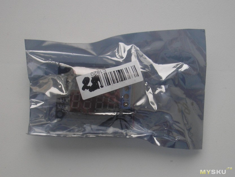
Увидел на странице магазина мощные резисторы (лежащие отдельно) и подумал, что это набор для самостоятельной сборки. Тестеры я ещё не собирал.
Оказалось, это обычные нагрузочные резисторы.
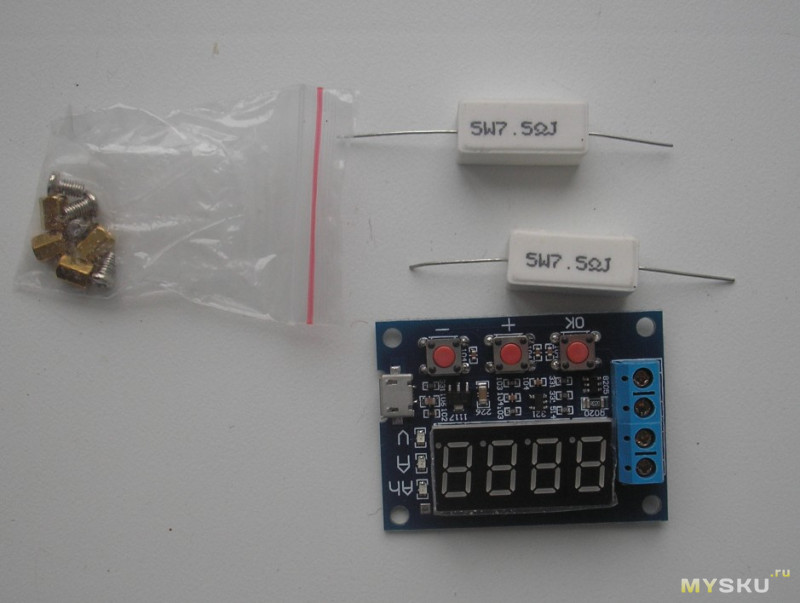
В принципе, это «готовый» полуфабрикат. Ничего собирать не надо. Просто бескорпусное (но законченное) изделие.
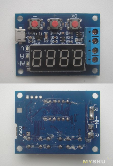
От флюса не отмыли. Но не впервой. Сам отмыл.
Комплектные резисторы имеют сопротивление 7,5 Ом (5 Вт).
Что куда подключать понятно из этого рисунка.
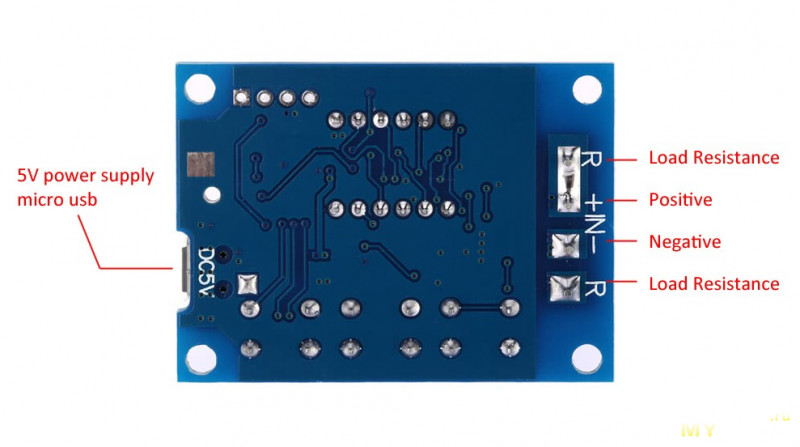
Одна из особенностей этого тестера в том, что для питания схемы и индикаторов используется отдельный вход 5 В (Micro USB).
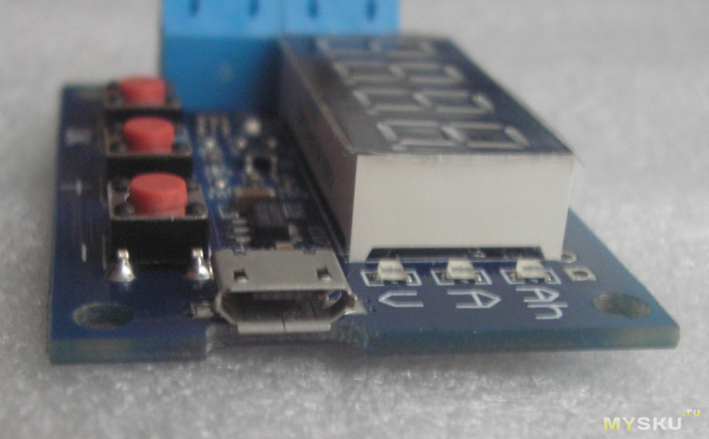
Энергия аккумулятора рассеивается только на нагрузочном резисторе. Энергопотребление схемы на точность показаний не влияет.
Работой тестера управляет микроконтроллер, установленный под 4-значным 7-сегментным светодиодным дисплеем.
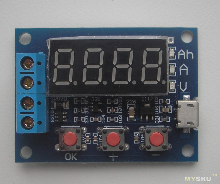
Сдвоенные MOSFET STT8205S (сопротивление каждого в открытом состоянии 0,028 Ом) подключены параллельно и коммутируют нагрузку. По паспорту до 20 В и 6 А (каждый).
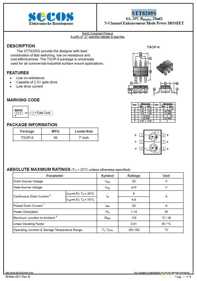
Ток разряда аккумулятора измеряется на R020 (0,02 Ом).
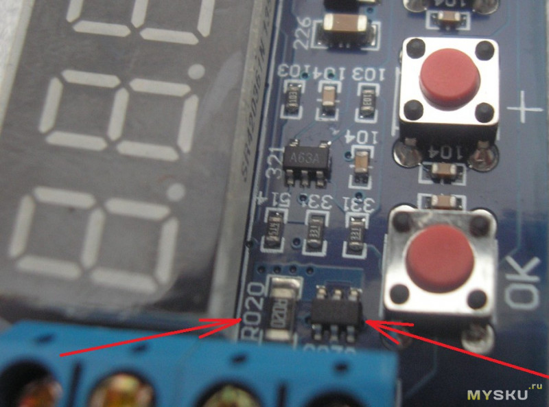
На печатке есть место подключения программатора.
Схема питается от стабилизатора напряжения AMS(LM)1117 (3,3 В).
Для подключения тестируемого аккумулятора используем клеммы IN. Плюс с минусом подписаны. Путать не рекомендую. Никаких защитных диодов не обнаружил.
Всего три кнопки управления. Управление простое, интуитивно понятное. Кнопками плюс и минус задаём напряжение отсечки аккумулятора. Кнопкой ОК включаем схему в работу.
Во время работы устройство может выражать своё возмущение неловкостью оператора.
Коды ошибок:
Err1: Напряжение аккумулятора выше 15 В.
Err2: Напряжение батареи ниже напряжения отсечки.
Err3: Большое сопротивление соединительных проводов.
Err4: Перегрузка по току (ток превышает 3,1А).
Лично я наблюдал только ошибку под номером два, когда подключил аккумулятор с напряжением менее напряжения отсечки.
Странно, но я не видел ошибки под номером один, хотя подавал на него напряжение и в 16 В.
Несколько слов по поводу того как работает и для чего это нужно.
Этот тестер позволяет определять реальную отдаваемую ёмкость аккумулятора (во время разряда).
Для этого первым делом нужно полностью зарядить аккумулятор. Затем подключить его к тестеру согласно схеме. Подключить нагрузку (заранее рассчитанную на ток разряда).
Когда нагрузочный резистор и аккумулятор подключены, включаем питание тестера (Micro USB 5 В).
Выставляем напряжение отсечки (напряжение, при котором устройство отключит нагрузку, дабы не угробить аккумулятор). Для двенадцативольтового аккума это может быть напряжение 10,8 В. Всё зависит от поставленных целей и задач. Оперируем кнопками (+) или (-).
Нажимаем кнопку ОК, чтобы начать тест.
Тестер попеременно будет высвечивать измеренные ёмкость (Ah)→ток→напряжение (по кругу).
По окончании (разряде аккумулятора до заданного предела) прибор будет пульсировать измеренным значением ёмкости.
Кто не смог понять моего косноязычия, просто посмотрите видео.
Первым делом проверил в работе.
Для наглядности в качестве нагрузки подключил лампочку. Удобно наблюдать подключение/отключение нагрузки. В качестве аккумуляторной батареи взял источник питания. На нём удобно проверять сработку напряжения отсечки.
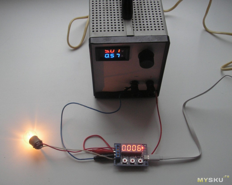
Сразу не понравилось то, что при включении питания (без аккумулятора) тестер уже показывал напряжение 0,06 В. Проблема решилось закорачиванием входных клемм.
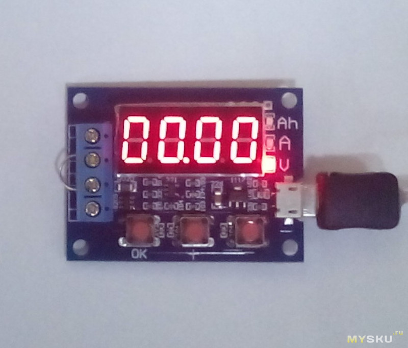
Отлегло. Здесь всё нормально.
Прогнал весь диапазон на установке П320 (по напряжению).
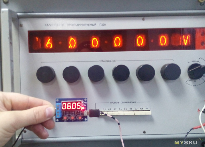
Погрешность присутствует. В заявленные пределы попадает. Но для меня погрешность в 1% кажется чрезмерно большой (к хорошему привыкаешь быстро).
А вот с током совсем беда. На холостом ходу 0,09 А.
Для пущей убедительности прогнал через установку П321. Неутешительно. Беглого взгляда достаточно, чтобы всё понять.
0 А→0.090
0,1 А→0.194
1,0 А→1.124
Вот такая печаль.
Пришлось искать способы калибровки. Нашёл… Но выполнять её могу посоветовать только в крайнем случае. Не у всех имеются образцовые источники.
В принципе, можно было бы даже согласиться с тем, что имею, если бы… китайцы не накосячили, когда при калибровке нуля забыли перемкнуть токовый вход тестера. 0,09 А при отключенной нагрузке – это перебор.
Калибровка:
Для выполнения калибровки требуется образцовый источник питания, который может обеспечивать 10,00 вольт и и 2,00 ампера.
→Удерживая все 3 кнопки, подключаем питание. Тестер максимально пытается нам помочь. Все надписи соответствуют тому, что предстоит сделать.
После того, как появятся OAOu, можно приступать к калибровке.
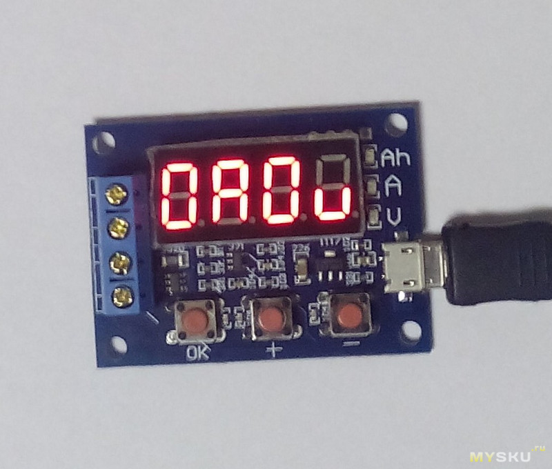
1. Калибровка нулей тока и напряжения (OAOu).
Закорачиваем все измерительные входы и нажимаем ОК.
2. Калибровка напряжения (10.0u).
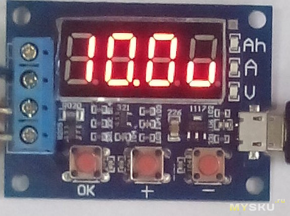
→Появляется надпись 10.0u. Подаём на входы 10 В с образцового источника и нажимаем ОК.
3. Калибровка тока (200А).
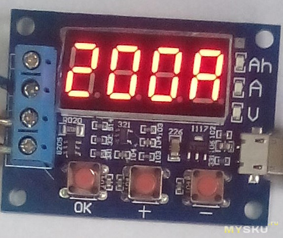
→Появляется надпись 200A. Подаём на входы 2 А с образцового источника и нажимаем ОК.
После этого запускается диагностика. Все записанные выше значения проверяются на соответствие (как именно я не знаю), и если они кажутся правильными, то они сохраняются в EEPROM. Подкорректировать что-то одно (нули, ток или напряжение) не получится. Диагностика не пропустит.
После калибровки показания вольтметра стали просто идеальными. Нет погрешности даже в сотых.
С током немного сложнее. Имеет место (я предполагаю) нагрев опорного резистора. Показания немного плавают.
0 А→0.000
0,01 А→0.010
0,1 А→0.101
0,5 А→0.499
1,0 А→0.998
2,0 А→1.997
Теперь стало поспокойнее. Такой результат меня полностью устроил.
Вот, в общем-то, и всё.
Подведу итог.
Неплохой приборчик для тестирования аккумуляторов. Можно и автомобильный аккумулятор проверить.
Из недостатков могу выделить только один: не может измерять количество пропускаемой энергии (это самый правильный способ оценки аккумуляторов).
Чтобы сделать правильный вывод, того, что написал, должно хватить.
На китайском рынке присутствуют другие очень похожие тестеры под маркой ZB2L3. Чем отличаются, не знаю. Описал работу того, что держу в руках.
Кому что-то неясно, задавайте вопросы. Надеюсь, хоть кому-то помог.
Удачи всем!
Товар для написания обзора предоставлен магазином. Обзор опубликован в соответствии с п.18 Правил сайта.