Cateye Padrone CC-PA100W — Cyclocomputer Manual

Mounting the computer

Mount the bracket
When mounting the bracket on a handlebar, adjust the angle of the bracket so that the back of the computer faces the speed sensor when the computer is attached.

Cutting band after mounting
Cut the bracket band so that cut end will not cause injury.
Mount the speed sensor
Mount the speed sensor in a position where the distance from the computer to the speed sensor is within the signal range.


Mount the magnet

Adjust the speed sensor and the magnet
The magnet passes through the speed sensor zone.

The clearance between the speed sensor and the magnet is within 5 mm (3/16″).
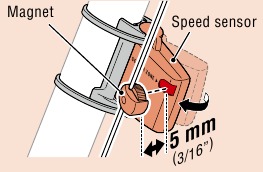
* The magnet may be mounted at any position on spoke as long as attachment conditions are satisfied.
Attach/detach computer

Test operation
After attaching the computer, rotate the front wheel gently to check that current speed is displayed on the computer. If the speed is not displayed, refer to the attachment conditions in steps 1, 2, and 4 again.
Setting up the computer
When using the computer for the first time, configure the initial settings.

Clear all data
Press the AC button on the back of the computer.
* All data is deleted and the computer is reset to its factory default settings.
Select the measurement unit
Select «km/h» or «mph«.
Set tire circumference
Enter the tire circumference of the front wheel in mm.
* Refer to «Tire circumference».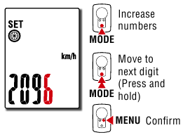
Set the clock
Each time MODE is pressed and held, settings switch from time display mode, to hours, to minutes.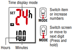
Setup is completed and the computer switches to the measurement screen. For instructions on how to start measurement, refer to «Starting measurement».
Tire circumference
Tire circumference can be determined by either of the following two methods:
- Measure the actual tire circumference (L)
After ensuring that the tire pressure is appropriate, sit on your bike, roll it forward so that the tire makes one full revolution (use the valve or other marking as a reference), and measure the distance traveled on the road.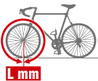
- Tire size chart
* The tire size or ETRTO code is indicated on the side of the tire.
| ETRTO | Tire size | L (mm) |
| 47-203 | 12×1.75 | 935 |
| 54-203 | 12×1.95 | 940 |
| 40-254 | 14×1.50 | 1020 |
| 47-254 | 14×1.75 | 1055 |
| 40-305 | 16×1.50 | 1185 |
| 47-305 | 16×1.75 | 1195 |
| 54-305 | 16×2.00 | 1245 |
| 28-349 | 16×1-1/8 | 1290 |
| 37-349 | 16×1-3/8 | 1300 |
| 32-369 | 17×1-1/4 (369) | 1340 |
| 40-355 | 18×1.50 | 1340 |
| 47-355 | 18×1.75 | 1350 |
| 32-406 | 20×1.25 | 1450 |
| 35-406 | 20×1.35 | 1460 |
| 40-406 | 20×1.50 | 1490 |
| 47-406 | 20×1.75 | 1515 |
| 50-406 | 20×1.95 | 1565 |
| 28-451 | 20×1-1/8 | 1545 |
| 37-451 | 20×1-3/8 | 1615 |
| 37-501 | 22×1-3/8 | 1770 |
| 40-501 | 22×1-1/2 | 1785 |
| 47-507 | 24×1.75 | 1890 |
| 50-507 | 24×2.00 | 1925 |
| 54-507 | 24×2.125 | 1965 |
| 25-520 | 24×1(520) | 1753 |
| 24×3/4 Tubular | 1785 | |
| 28-540 | 24×1-1/8 | 1795 |
| 32-540 | 24×1-1/4 | 1905 |
| 25-559 | 26×1(559) | 1913 |
| 32-559 | 26×1.25 | 1950 |
| 37-559 | 26×1.40 | 2005 |
| 40-559 | 26×1.50 | 2010 |
| 47-559 | 26×1.75 | 2023 |
| 50-559 | 26×1.95 | 2050 |
| 54-559 | 26×2.10 | 2068 |
| 57-559 | 26×2.125 | 2070 |
| 58-559 | 26×2.35 | 2083 |
| 75-559 | 26×3.00 | 2170 |
| 28-590 | 26×1-1/8 | 1970 |
| 37-590 | 26×1-3/8 | 2068 |
| 37-584 | 26×1-1/2 | 2100 |
| 650C Tubular 26×7/8 | 1920 | |
| 20-571 | 650x20C | 1938 |
| 23-571 | 650x23C | 1944 |
| 25-571 | 650x25C 26×1(571) | 1952 |
| 40-590 | 650x38A | 2125 |
| 40-584 | 650x38B | 2105 |
| 25-630 | 27×1(630) | 2145 |
| 28-630 | 27×1-1/8 | 2155 |
| 32-630 | 27×1-1/4 | 2161 |
| 37-630 | 27×1-3/8 | 2169 |
| 40-584 | 27.5×1.50 | 2079 |
| 50-584 | 27.5×1.95 | 2090 |
| 54-584 | 27.5×2.1 | 2148 |
| 57-584 | 27.5×2.25 | 2182 |
| 18-622 | 700x18C | 2070 |
| 19-622 | 700x19C | 2080 |
| 20-622 | 700x20C | 2086 |
| 23-622 | 700x23C | 2096 |
| 25-622 | 700x25C | 2105 |
| 28-622 | 700x28C | 2136 |
| 30-622 | 700x30C | 2146 |
| 32-622 | 700x32C | 2155 |
| 700C Tubular | 2130 | |
| 35-622 | 700x35C | 2168 |
| 38-622 | 700x38C | 2180 |
| 40-622 | 700x40C | 2200 |
| 42-622 | 700x42C | 2224 |
| 44-622 | 700x44C | 2235 |
| 45-622 | 700x45C | 2242 |
| 47-622 | 700x47C | 2268 |
| 54-622 | 29×2.1 | 2288 |
| 56-622 | 29×2.2 | 2298 |
| 60-622 | 29×2.3 | 2326 |
Starting measurement

MODE operation when mounted on bracket
When the computer is mounted on the bracket, pressing the dot section on the computer depresses the MODE button.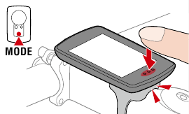
Switching current function
Pressing MODE switches the current function displayed at the bottom of the screen.
* Av displays.E instead of the measurement value when Tm exceeds approximately 100 hours or Dst exceeds 9999.99 km. Reset the computer.
On the measurement screen, press MENU to go to the menu screen. Various settings can be changed on the menu screen.
Starting/stopping measurement
Measurement starts automatically when the bicycle moves. During measurement the measurement unit (km/h or mph) flashes.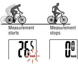
Resetting data
Pressing MODE for 2 seconds when on the measurement screen resets all measurement data to 0 (excluding Odo).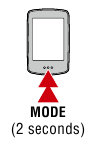
Power-saving function
If the computer does not receive any signal for 10 minutes, the power-saving screen is activated and only the clock is displayed.
If MODE is pressed or a sensor signal is received while the powersaving screen is activated, the computer returns to the measurement screen.
* When the computer is left on the power-saving screen for 1 hour, the display only shows the measurement unit. When the computer is in this state, you can return to the measurement screen by pressing MODE.
Using the stopwatch
You can display a stopwatch that lets you count time regardless of whether measurement is started or stopped.
To use the stopwatch, set the stopwatch setting on the menu screen to ON.
For instructions on how to set the stopwatch, refer to «Stopwatch».
Stopwatch operation
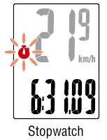
| Start/stop | Press MODE for 1 second when the stopwatch is displayed. During counting the  icon flashes. icon flashes. |
| Reset | Press MODE for 4 seconds when the stopwatch is displayed. |
* Start, stop, and reset operations of the stopwatch are performed separately to measurement, and do not affect other measurements.
* The stopwatch continues counting regardless of the power-saving state. During counting the icon flashes on every screen except for the menu screen.
Changing settings
On the measurement screen, press MENU to go to the menu screen. Various settings can be changed on the menu screen.
* After changing settings, always press MENU to confirm changes.
* When the menu screen is left on for 1 minute, the computer returns to the measurement screen.

Manual distance input
Lets you set total distance traveled manually. (Fractions cannot be entered.)
* Setting an arbitrary value for total distance allows you to start from the value you entered. This is useful when you have just purchased a new bicycle or when replacing the computer battery.
Warning / Caution
- Do not concentrate on the computer while riding. Always ride safely.
- Mount the magnet, sensor, and bracket securely, and check them periodically to ensure that they are not loose.
- If a battery is swallowed accidentally, consult a doctor immediately.
- Do not leave the computer in direct sunlight for a long period of time.
- Do not disassemble the computer.
- Do not drop the computer. Doing so may result in malfunction or damage.
- When pressing the MODE button with the computer installed on the bracket, press the area around the dot section on the front of the computer. Pressing other areas strongly may result in malfunction or damage.
- Always tighten the bracket band dial by hand. Using a tool or other object to tighten the dial may crush the screw thread.
- When cleaning the computer and accessories, do not use thinners, benzine, or alcohol.
- Risk of explosion if battery is replaced by an incorrect type. Dispose of used batteries according to local regulations.
- The LCD screen may be distorted when viewed through polarized sunglass lenses.
Wireless Sensor
The speed sensor is designed with a maximum signal range of 70 cm (27″), to reduce the chance of interference. (The signal range is intended to serve as a rough guide only.)
When handling the wireless sensor, note the following:
- Signals cannot be received if the distance between the speed sensor and the computer is too large.
- Signal range may be shortened due to low temperature and flat batteries.
- Signals can be received only when the back of the computer is facing the speed sensor.
Interference may occur, resulting in malfunction, if the computer is:
- Near a TV, PC, radio, or motor, or in a car or train.
- Close to a railroad crossing, railway tracks, TV transmitter station, or radar station.
- Used with other wireless devices or certain battery-powered lights.
Frequency Band: 19 kHz
Radiated Power: −31.7 dBm
Hereby, CATEYE Co., Ltd. declares that the radio equipment type CC-PA100W is in compliance with Directive 2014/53/EU.
The full text of the EU declaration of conformity is available at the following internet address: cateye.com/doc
Maintenance
If the computer or accessories become dirty, clean with a soft cloth which is moistened with mild soap.
Replacing the battery
Troubleshooting
Speed is not displayed.
- Is there too much clearance between the speed sensor and the magnet?
(Clearance should be within 5 mm (3/16″).) - Does the magnet pass through the sensor zone correctly? Adjust the position of the magnet and/or the speed sensor.
- Is the computer mounted at the correct angle? Ensure that the back of the computer faces the speed sensor.
- Are the computer and the speed sensor mounted at the correct distance apart?
(Clearance should be from 20 to 70 cm (8″ to 27″).)
Ensure that the speed sensor is within range. - Is the computer or speed sensor battery flat?
* Battery performance diminishes in winter.
If the computer reacts only when it is close to the speed sensor, the problem may be due to weak batteries.
Replace the batteries with new ones as described in «Replacing the battery».
The display remains blank when the button is pressed
Replace the computer battery as described in «Replacing the battery».
Incorrect data appear
Clear all according to the procedure described in «Setting up the computer».
Main specifications
| Batteries used Battery life |
Computer | Lithium battery (CR2032) x1 / Approx. 1 year (If used for 1 hour a day; actual battery life will vary depending on usage conditions.) |
| Speed sensor | Lithium battery (CR2032) x1 / Total distance approx. 10000 km [6,250 miles] |
|
| * Average value when used at temperature of 20°C with computer and sensor mounted 65 cm apart. * Life of pre-installed battery may be shorter than indicated above. |
||
| Controller | 4 bit, 1-chip microcomputer (Crystal controlled oscillator) |
|
| Display | Liquid crystal | |
| Sensor | Non-contact magnetic sensor | |
| Signal range | 20 to 70 cm (8″ to 27″) | |
| Tire circumference range | 0100 mm – 3999 mm (Initial value: 2096 mm) |
|
| Operating temperature range | 32°F – 104°F (0°C – 40°C) (Guaranteed operating temperature range: Display visibility may deteriorate outside this range.) |
|
| Dimensions/ weight |
Computer | 2-21/32″ x 1-11/16″ x 9/16″ (67.5 x 43 x 14.5 mm) / 1.1 oz (31.5 g) |
| Speed sensor | 1-5/8″ x 1-13/32″ x 19/32″ (41.5 x 36 x 15 mm) / 0.5 oz (15 g) |
* Specifications and design are subject to change without notice.
LIMITED WARRANTY
2-Years Computer/Speed Sensor Only
(Accessories and Battery Consumption Excluded)
CatEye cycle computers are warranted to be free of defects from materials and workmanship for a period of two years from original purchase. If the product fails to work due to normal use, CatEye will repair or replace the defect at no charge. Service must be performed by CatEye or an authorized retailer.
Standard accessories
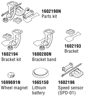
Optional accessories

CAT EYE CO., LTD.
2-8-25, KUWAZU, HIGASHI SUMIYOSHI-KU, OSAKA, JAPAN 546-0041
For inquiries, please visit https://cateye.com/intl/contact/
[For US Customers]
CATEYE AMERICA, INC.
Please visit https://www.cateyeamerica.com/contact-us/
Toll Free: 800.5.CATEYE

Documents / Resources
References
Download manual
Here you can download full pdf version of manual, it may contain additional safety instructions, warranty information, FCC rules, etc.
Download Cateye Padrone CC-PA100W — Cyclocomputer Manual

Setup is completed and the computer switches to the measurement screen. For instructions on how to start measurement, refer to «Starting measurement».
Tire circumference
Tire circumference can be determined by either of the following two methods:
- Measure the actual tire circumference (L)
After ensuring that the tire pressure is appropriate, sit on your bike, roll it forward so that the tire makes one full revolution (use the valve or other marking as a reference), and measure the distance traveled on the road. - Tire size chart
* The tire size or ETRTO code is indicated on the side of the tire.
| ETRTO | Tire size | L (mm) |
| 47-203 | 12×1.75 | 935 |
| 54-203 | 12×1.95 | 940 |
| 40-254 | 14×1.50 | 1020 |
| 47-254 | 14×1.75 | 1055 |
| 40-305 | 16×1.50 | 1185 |
| 47-305 | 16×1.75 | 1195 |
| 54-305 | 16×2.00 | 1245 |
| 28-349 | 16×1-1/8 | 1290 |
| 37-349 | 16×1-3/8 | 1300 |
| 32-369 | 17×1-1/4 (369) | 1340 |
| 40-355 | 18×1.50 | 1340 |
| 47-355 | 18×1.75 | 1350 |
| 32-406 | 20×1.25 | 1450 |
| 35-406 | 20×1.35 | 1460 |
| 40-406 | 20×1.50 | 1490 |
| 47-406 | 20×1.75 | 1515 |
| 50-406 | 20×1.95 | 1565 |
| 28-451 | 20×1-1/8 | 1545 |
| 37-451 | 20×1-3/8 | 1615 |
| 37-501 | 22×1-3/8 | 1770 |
| 40-501 | 22×1-1/2 | 1785 |
| 47-507 | 24×1.75 | 1890 |
| 50-507 | 24×2.00 | 1925 |
| 54-507 | 24×2.125 | 1965 |
| 25-520 | 24×1(520) | 1753 |
| 24×3/4 Tubular | 1785 | |
| 28-540 | 24×1-1/8 | 1795 |
| 32-540 | 24×1-1/4 | 1905 |
| 25-559 | 26×1(559) | 1913 |
| 32-559 | 26×1.25 | 1950 |
| 37-559 | 26×1.40 | 2005 |
| 40-559 | 26×1.50 | 2010 |
| 47-559 | 26×1.75 | 2023 |
| 50-559 | 26×1.95 | 2050 |
| 54-559 | 26×2.10 | 2068 |
| 57-559 | 26×2.125 | 2070 |
| 58-559 | 26×2.35 | 2083 |
| 75-559 | 26×3.00 | 2170 |
| 28-590 | 26×1-1/8 | 1970 |
| 37-590 | 26×1-3/8 | 2068 |
| 37-584 | 26×1-1/2 | 2100 |
| 650C Tubular 26×7/8 | 1920 | |
| 20-571 | 650x20C | 1938 |
| 23-571 | 650x23C | 1944 |
| 25-571 | 650x25C 26×1(571) | 1952 |
| 40-590 | 650x38A | 2125 |
| 40-584 | 650x38B | 2105 |
| 25-630 | 27×1(630) | 2145 |
| 28-630 | 27×1-1/8 | 2155 |
| 32-630 | 27×1-1/4 | 2161 |
| 37-630 | 27×1-3/8 | 2169 |
| 40-584 | 27.5×1.50 | 2079 |
| 50-584 | 27.5×1.95 | 2090 |
| 54-584 | 27.5×2.1 | 2148 |
| 57-584 | 27.5×2.25 | 2182 |
| 18-622 | 700x18C | 2070 |
| 19-622 | 700x19C | 2080 |
| 20-622 | 700x20C | 2086 |
| 23-622 | 700x23C | 2096 |
| 25-622 | 700x25C | 2105 |
| 28-622 | 700x28C | 2136 |
| 30-622 | 700x30C | 2146 |
| 32-622 | 700x32C | 2155 |
| 700C Tubular | 2130 | |
| 35-622 | 700x35C | 2168 |
| 38-622 | 700x38C | 2180 |
| 40-622 | 700x40C | 2200 |
| 42-622 | 700x42C | 2224 |
| 44-622 | 700x44C | 2235 |
| 45-622 | 700x45C | 2242 |
| 47-622 | 700x47C | 2268 |
| 54-622 | 29×2.1 | 2288 |
| 56-622 | 29×2.2 | 2298 |
| 60-622 | 29×2.3 | 2326 |
Starting measurement
MODE operation when mounted on bracket
When the computer is mounted on the bracket, pressing the dot section on the computer depresses the MODE button.
Switching current function
Pressing MODE switches the current function displayed at the bottom of the screen.
* Av displays.E instead of the measurement value when Tm exceeds approximately 100 hours or Dst exceeds 9999.99 km. Reset the computer.
On the measurement screen, press MENU to go to the menu screen. Various settings can be changed on the menu screen.
Starting/stopping measurement
Measurement starts automatically when the bicycle moves. During measurement the measurement unit (km/h or mph) flashes.
Resetting data
Pressing MODE for 2 seconds when on the measurement screen resets all measurement data to 0 (excluding Odo).
Power-saving function
If the computer does not receive any signal for 10 minutes, the power-saving screen is activated and only the clock is displayed.
If MODE is pressed or a sensor signal is received while the powersaving screen is activated, the computer returns to the measurement screen.
* When the computer is left on the power-saving screen for 1 hour, the display only shows the measurement unit. When the computer is in this state, you can return to the measurement screen by pressing MODE.
Using the stopwatch
You can display a stopwatch that lets you count time regardless of whether measurement is started or stopped.
To use the stopwatch, set the stopwatch setting on the menu screen to ON.
For instructions on how to set the stopwatch, refer to «Stopwatch».
Stopwatch operation
| Start/stop | Press MODE for 1 second when the stopwatch is displayed. During counting the icon flashes. |
| Reset | Press MODE for 4 seconds when the stopwatch is displayed. |
* Start, stop, and reset operations of the stopwatch are performed separately to measurement, and do not affect other measurements.
* The stopwatch continues counting regardless of the power-saving state. During counting the icon flashes on every screen except for the menu screen.
Changing settings
On the measurement screen, press MENU to go to the menu screen. Various settings can be changed on the menu screen.
* After changing settings, always press MENU to confirm changes.
* When the menu screen is left on for 1 minute, the computer returns to the measurement screen.
Manual distance input
Lets you set total distance traveled manually. (Fractions cannot be entered.)
* Setting an arbitrary value for total distance allows you to start from the value you entered. This is useful when you have just purchased a new bicycle or when replacing the computer battery.
Warning / Caution
- Do not concentrate on the computer while riding. Always ride safely.
- Mount the magnet, sensor, and bracket securely, and check them periodically to ensure that they are not loose.
- If a battery is swallowed accidentally, consult a doctor immediately.
- Do not leave the computer in direct sunlight for a long period of time.
- Do not disassemble the computer.
- Do not drop the computer. Doing so may result in malfunction or damage.
- When pressing the MODE button with the computer installed on the bracket, press the area around the dot section on the front of the computer. Pressing other areas strongly may result in malfunction or damage.
- Always tighten the bracket band dial by hand. Using a tool or other object to tighten the dial may crush the screw thread.
- When cleaning the computer and accessories, do not use thinners, benzine, or alcohol.
- Risk of explosion if battery is replaced by an incorrect type. Dispose of used batteries according to local regulations.
- The LCD screen may be distorted when viewed through polarized sunglass lenses.
Wireless Sensor
The speed sensor is designed with a maximum signal range of 70 cm (27″), to reduce the chance of interference. (The signal range is intended to serve as a rough guide only.)
When handling the wireless sensor, note the following:
- Signals cannot be received if the distance between the speed sensor and the computer is too large.
- Signal range may be shortened due to low temperature and flat batteries.
- Signals can be received only when the back of the computer is facing the speed sensor.
Interference may occur, resulting in malfunction, if the computer is:
- Near a TV, PC, radio, or motor, or in a car or train.
- Close to a railroad crossing, railway tracks, TV transmitter station, or radar station.
- Used with other wireless devices or certain battery-powered lights.
Frequency Band: 19 kHz
Radiated Power: −31.7 dBm
Hereby, CATEYE Co., Ltd. declares that the radio equipment type CC-PA100W is in compliance with Directive 2014/53/EU.
The full text of the EU declaration of conformity is available at the following internet address: cateye.com/doc
Maintenance
If the computer or accessories become dirty, clean with a soft cloth which is moistened with mild soap.
Replacing the battery
Troubleshooting
Speed is not displayed.
- Is there too much clearance between the speed sensor and the magnet?
(Clearance should be within 5 mm (3/16″).) - Does the magnet pass through the sensor zone correctly? Adjust the position of the magnet and/or the speed sensor.
- Is the computer mounted at the correct angle? Ensure that the back of the computer faces the speed sensor.
- Are the computer and the speed sensor mounted at the correct distance apart?
(Clearance should be from 20 to 70 cm (8″ to 27″).)
Ensure that the speed sensor is within range. - Is the computer or speed sensor battery flat?
* Battery performance diminishes in winter.
If the computer reacts only when it is close to the speed sensor, the problem may be due to weak batteries.
Replace the batteries with new ones as described in «Replacing the battery».
The display remains blank when the button is pressed
Replace the computer battery as described in «Replacing the battery».
Incorrect data appear
Clear all according to the procedure described in «Setting up the computer».
Main specifications
| Batteries used Battery life |
Computer | Lithium battery (CR2032) x1 / Approx. 1 year (If used for 1 hour a day; actual battery life will vary depending on usage conditions.) |
| Speed sensor | Lithium battery (CR2032) x1 / Total distance approx. 10000 km [6,250 miles] |
|
| * Average value when used at temperature of 20°C with computer and sensor mounted 65 cm apart. * Life of pre-installed battery may be shorter than indicated above. |
||
| Controller | 4 bit, 1-chip microcomputer (Crystal controlled oscillator) |
|
| Display | Liquid crystal | |
| Sensor | Non-contact magnetic sensor | |
| Signal range | 20 to 70 cm (8″ to 27″) | |
| Tire circumference range | 0100 mm – 3999 mm (Initial value: 2096 mm) |
|
| Operating temperature range | 32°F – 104°F (0°C – 40°C) (Guaranteed operating temperature range: Display visibility may deteriorate outside this range.) |
|
| Dimensions/ weight |
Computer | 2-21/32″ x 1-11/16″ x 9/16″ (67.5 x 43 x 14.5 mm) / 1.1 oz (31.5 g) |
| Speed sensor | 1-5/8″ x 1-13/32″ x 19/32″ (41.5 x 36 x 15 mm) / 0.5 oz (15 g) |
* Specifications and design are subject to change without notice.
LIMITED WARRANTY
2-Years Computer/Speed Sensor Only
(Accessories and Battery Consumption Excluded)
CatEye cycle computers are warranted to be free of defects from materials and workmanship for a period of two years from original purchase. If the product fails to work due to normal use, CatEye will repair or replace the defect at no charge. Service must be performed by CatEye or an authorized retailer.
Standard accessories
Optional accessories
CAT EYE CO., LTD.
2-8-25, KUWAZU, HIGASHI SUMIYOSHI-KU, OSAKA, JAPAN 546-0041
For inquiries, please visit https://cateye.com/intl/contact/
[For US Customers]
CATEYE AMERICA, INC.
Please visit https://www.cateyeamerica.com/contact-us/
Toll Free: 800.5.CATEYE
Documents / Resources
References
Download manual
Here you can download full pdf version of manual, it may contain additional safety instructions, warranty information, FCC rules, etc.
Download Cateye Padrone CC-PA100W — Cyclocomputer Manual
2
3
4
1
Appendix
SET
C A T E Y E
PADRONE
CYCLOCOMPUTER
CC-PA100W
1
•
This instruction manual is subject to change
without notice. See our website for the latest
instruction manual (PDF).
•
Please visit our website, where a detailed
Quick Start manual containing videos can be
downloaded.
http://www.cateye.com/en/prod-
ucts/detail/CC-PA100W/manual/
Setting up the
computer
Mounting the
computer
Starting
measurement
Changing settings
Warning/Caution
Product Warranty, etc.
инструкцияCateye Padrone CC-PA100W

2
3
4
1
Appendix
SET
PADRONE
CYCLOCOMPUTER
CC-PA100W
1
•
Thisinstructionmanualissubjecttochange
withoutnotice.Seeourwebsiteforthelatest
instructionmanual(PDF).
•
Pleasevisitourwebsite,whereadetailed
QuickStartmanualcontainingvideoscanbe
downloaded.
http://www.cateye.com/products/detail/CC-PA100W/manual/
Setting up the
computer
Mounting the
computer
Starting
measurement
Changing settings
Warning/Caution
Product Warranty, etc.
Посмотреть инструкция для Cateye Padrone CC-PA100W бесплатно. Руководство относится к категории велокомпьютеры, 6 человек(а) дали ему среднюю оценку 8.6. Руководство доступно на следующих языках: английский. У вас есть вопрос о Cateye Padrone CC-PA100W или вам нужна помощь? Задайте свой вопрос здесь
Главная
Не можете найти ответ на свой вопрос в руководстве? Вы можете найти ответ на свой вопрос ниже, в разделе часто задаваемых вопросов о Cateye Padrone CC-PA100W.
Аккумулятор в моем устройстве велокомпьютер начал ржаветь. Безопасно ли пользоваться устройством?
Продукт безопасен для использования после надлежащей очистки. Извлеките аккумулятор, надев перчатки, и очистите аккумуляторный отсек зубной щеткой, смоченной уксусом. После высыхания установите в устройство новые аккумуляторы.
Что такое GPS?
GPS — это система, которая может использоваться в любой точке мира для определения вашего местоположения с помощью спутников.
Что означает аббревиатура GPS?
Аббревиатура GPS расшифровывается как Global Positioning System, т. е. система глобального позиционирования.
Необходим ли интернет для GPS?
Нет, для использования GPS не требуется интернет.
Инструкция Cateye Padrone CC-PA100W доступно в русский?
К сожалению, у нас нет руководства для Cateye Padrone CC-PA100W, доступного в русский. Это руководство доступно в английский.
Не нашли свой вопрос? Задайте свой вопрос здесь
![]()
C A T E Y E PADRONE
CYCLOCOMPUTER
CC-PA100W
•Deze handleiding kan zonder voorafgaande kennisgeving worden gewijzigd. Zie onze website voor de nieuwste handleiding (PDF).
•Bezoek onze website waar u een gedetailleerde snelstartgids met video’s kunt downloaden.
http://www.cateye.com/nl/products/ 


 detail/CC-PA100W/manual/


De computer installeren
De computer instellen
De meting starten
De instellingen wijzigen
Waarschuwing / Pas op Productgarantie enz.
1

Het apparaat op uw fiets monteren
|
Beugelband |
Anti-slip rubber |
Snelheidssensor |
Magneet |
|
Beugel |
Stelknop |
Rubberkussen |
Kabelbinder |
|
sensor |
|||
|
(x2) |
|
1 |
Monteer de beugel |
|
|
• Bij montage op de stuurpen |
||
|
Beugelband |
Anti-slip rubber |
Beugel
• Bij montage op het stuur
|
Beugelband |
Anti-slip rubber |
|
Beugel |
|
|
Als u de beugel op het stuur bevestigt, zorg |
Juist |
|
dan dat de achterkant van de computer in |
|
|
de richting van de snelheidssensor wijst. |
|
Knip de band na bevestiging door |
Stelknop |
LET OP:
Knip de band zo door dat het afgesneden einde geen letsel veroorzaakt.
Stuurpen
Stuur
Onjuist
 Knippen
2

De computer installeren
2 Monteer de snelheidssensor
• Montage op rechter voorvork
Monteer de snelheidssensor in een stand waarbij de afstand van de computer tot de snelheidssensor binnen het signaalbereik ligt.
|
• Montage op linker voorvork |
Max. |
|
|
70 cm |
Snelheidssensor
Rubberkussen sensor
3 Monteer de magneet
Kabelbinder
Strak  aantrekken
Knippen
Magneet
|
Naar sensorzone |
||||
|
Spaak |
3

De computer installeren
4 De snelheidssensor en magneet instellen
|
De magneet gaat door de |
De ruimte tussen de snelheids- |
|
sensorzone. |
sensor en de magneet is hoog- |
|
stens 5 mm. |
Magneet
Sensor zone
SENSOR ZONE
Snelheidssensor
Snelheidssensor
Magneet
ZONE
5 mm
*De magneet kan in elke stand op de spaak worden geplaatst mits aan de bevestigingsvoorwaarden voldaan wordt.
5 De computer vastzetten/losmaken
Houd de computer vast.
Klik
Druk naar buiten zodat de voorkant omhoog komt.
6 Testbediening
Draai na bevestiging van de computer het voorwiel langzaam om te controleren of de huidige snelheid op de computer wordt weergegeven.
Als de snelheid niet wordt weergegeven, raadpleeg dan nogmaals de aansluitvoorwaarden in de stappen 1, 2 en 4 .
.
4
 Loading…
You can only view or download manuals with
Sign Up and get 5 for free
Upload your files to the site. You get 1 for each file you add
Get 1 for every time someone downloads your manual
Buy as many as you need
-
Pioneer SGY-PM910H2
3OHDVHUHDGWKHImportant Information for the UserLQWKHSURGXFWER[IRUSURGXFWZDUQLQJVDQGRWKHULPSRUWDQWVDIHW\LQIRUPDWLRQ3HGDOLQJ0RQLWRU6HQVRUSGY-PM910H6*<30+/6*<30+5Installation Manual (for installing only) …
SGY-PM910H2 Kitchen Appliances, 55
-
RACOR PLB-4R
H O M E S T O R A G E P R O D U C T SWWW.RACORSTORAGESOLUTIONS.COMFREE STANDING BIKE RACK | PLB-4RINSTRUCTIONSPARTS LISTTOOLS REQUIREDx2 Curved base x1 V framex1 Straight bottom sectionx1 Straight top sectionx8 Universal armsx6 Rubber feetx4 Long hex socket cap screw x8 Short hex socket cap screwx4 Hex …
PLB-4R Bicycle Accessories, 3
-
Kasanova E-mootika
I TAE-MOOTIKA E-MOOTIKAMANUALE DI ISTRUZIONI MANUALE DI ISTRUZIONII TAManuale di istruzioni — Instruction manualScannerizza il codice sopra riportato oppure collegati al canale YouTube Kasanova per vedere il Video Tutorial dell’assemblaggio di E-MootikaQR CODE …
E-mootika Bicycle Accessories, 153
-
Shimano DH-3N80
DESCRIPTIONSHIMANOCODE NO.ITEMNO.**0708-2732A123456789Complete Quick Release 133 mm (5-1/4″)Connector Cap & CoverInternal Assembly (Axle Length 108 mm) for DH-3N80Internal Assembly (Axle Length 108 mm) for DH-2N80-EGrease GuardSteel Ball (3/16″) 20 pcs.Seal RingCone (M14 x 10.73 mm) w/Dust CoverLeft Hand …
DH-3N80 Bicycle Accessories, 2
-
Tern Bicycles Axis Adjustable Stem
EN For installation by a trained bicycle technician only. Do not attempt to install this component without proper tools, training and/or knowledge. If you are unsure how to service or install this component, please take it and your bike to a trained bicycle technician.ES Para su instalación exclusiva por un técnic …
Axis Adjustable Stem Bicycle Accessories, 2
-
Shimano EW-WU101
One Holland, Irvine, California 92618, U.S.A. Phone: +1-949-951-5003High Tech Campus 92, 5656 AG Eindhoven, The Netherlands Phone: +31-402-6122223-77 Oimatsu-cho, Sakai-ku, Sakai-shi, Osaka 590-8577, JapanPlease note: specifi cations are subject to change for improvement without notice. (English) © Jun. 2017 by Shim …
EW-WU101 Bicycle Accessories, 1
-
Bosch PowerPack 500
Robert Bosch GmbHBosch eBike Systems72703 ReutlingenGERMANYwww.bosch-ebike.com0 275 007 XPX (2016.04) T / 57 WEUActive Line/Performance Line Active Line/Performance LinePowerPack 300 | 400 | 5000 275 007 509 | 0 275 007 510 | 0 275 007 511 | 0 275 007 5120 275 007 513 | 0 275 007 514 | 0 275 007 5220 275 007 529 | 0 2 …
PowerPack 500 Power Pack, 56