
I 0226 — 1
GB
GB
Instructions for use
I
Contents Page
1 — GENERAL………………………………………………………………………………………………………………………………………………….3
1.1 — GENERAL SAFETY REGULATIONS …………………………………………………………………………………………………3
1.1.1 — STANDARD SAFETY DEVICES …………………………………………………………………………………………….3
1.2 — FIELD OF APPLICATION …………………………………………………………………………………………………………………3
1.3 — OVERALL DIMENSIONS …………………………………………………………………………………………………………………3
1.4- SPECIFICATION …………………………………………………………………………………………………………………………….4
2 — HANDLING, HOISTING ……………………………………………………………………………………………………………………………..4
3 — START-UP ………………………………………………………………………………………………………………………………………………..5
3.1 — ANCHORING ………………………………………………………………………………………………………………………………….5
3.2 — ELECTRICAL CONNECTION . ………………………………………………………………………………………………………….5
3.3 — PNEUMATIC CONNECTION (Versions SE )…………………………………………………………………………………………5
3.4 — EXTRA SAFETY DEVICES (VERSION SE ) ……………………………………………………………………………………….5
3.5 — ADAPTER MOUNTING ……………………………………………………………………………………………………………………5
3.5 — WHEEL GUARD ASSEMBLY AND ADJUSTMENT ……………………………………………………………………………….8
3.7 — SPACER WD ……………………………………………………………………………………………………………………………………8
4 — CONTROLS AND COMPONENTS ……………………………………………………………………………………………………………..8
4.1 — BRAKE PEDAL…………………………………………………………………………………………………………………………………8
4.2 — PNEUMATIC LOCKING PEDAL (Version P) …………………………………………………………………………………………8
4.3 — AUTOMATIC RIM DISTANCE AND DIAMETER GAUGE ……………………………………………………………………….9
4.4 — AUTOMATIC WIDTH GAUGE (OPTIONAL) …………………………………………………………………………………………9
4.5 — AUTOMATIC WHEEL POSITIONING ………………………………………………………………………………………………….9
4.6 — CONTROL PANEL AND DISPLAY …………………………………………………………………………………………………..10
4.6.1 CONTROL OF THE FUNCTIONS MENU ………………………………………………………………………………….11
5 — INDICATIONS AND USE OF THE WHEEL BALANCER ………………………………………………………………………………12
5.1 — DOUBLE OPERATOR PROGRAM ……………………………………………………………………………………………………12
5.2 — PRESETTING OF WHEEL DIMENSIONS ……………………………………………………………………………………….12
5.2.1 — AUTOMATIC PRESETTING …………………………………………………………………………………………………12
5.2.1.1 — “AUTOMATIC WIDTH” OPTION …………………………………………………………………………………………..13
5.2.1.2 — WHEEL ALU-S ………………………………………………………………………………………………………………….13
5.2.2 — MANUAL PRESETTTING ……………………………………………………………………………………………………14
5.3 — RECALCULATION OF THE UNBALANCE ………………………………………………………………………………………..15
5.4 — RESULT OF MEASUREMENT ………………………………………………………………………………………………………..15
5.4.1 — INDICATION OF EXACT CORRECTION POSITION IN ALU-S ………………………………………………..15
5.4.2 — RESOLUTION OF THE UNBALANCE (SPLIT) ……………………………………………………………………….16
5.4.3 — UNBALANCE OPTIMIZATION ……………………………………………………………………………………………..18
5.4.4 — ALU AND STATIC MODES …………………………………………………………………………………………………..19
5.4.5 -AUTOMATIC MINIMIZATION OF STATIC UNBALANCE …………………………………………………………….19
5.5 — ECCENTRICTY MEASUREMENT (OPTION)……………………………………………………………………………………..20
6 — SET UP ………………………………………………………………………………………………………………………………………………….21
6.1 — SELF-DIAGNOSTICS …………………………………………………………………………………………………………………….21
6.2 — SELF-CALIBRATION ……………………………………………………………………………………………………………………..22
6.3 — SCREEN SAVER……………………………………………………………………………………………………………………………23
6.4 — TYPE OF DISPLAY OF UNBALANCE PHASE ……………………………………………………………………………………24
6.5 — AUTOMATIC GAUGES ………………………………………………………………………………………………………………….25
6.5.1 — RIM DISTANCE GAUGE ……………………………………………………………………………………………………..25
6.5.2 — DIAMETER GAUGE ……………………………………………………………………………………………………………25
6.5.3 — WIDTH GAUGE (OPTIONAL)) ……………………………………………………………………………………………….26
6.6 — AMBIENT TEMPERATURE ………………………………………………………………………………………………………………26
7 — ERRORS ………………………………………………………………………………………………………………………………………………..26
7.1 — INCONSISTENT UNBALANCE READINGS ……………………………………………………………………………………..27
8 — ROUTINE MAINTENANCE ……………………………………………………………………………………………………………………….27
8.1 — TO REPLACE THE FUSES ………………………………………………………………………………………………………………27
9 — RECOMMENDED SPARE PARTS LIST……………………………………………………………………………………………………….28
GB
Use and maintenance manual
General Index
1. FOREWORD
1.1 GENERAL
1.2 PURPOSE OF THE MANUAL
1.3 WHERE AND HOW TO KEEP THE MANUAL
1.5 COLLABORATION WITH USERS
1.6 MANUFACTURER
1.7 MANUFACTURER’S RESPONSIBILITY AND WARRANTY
1.7.1 Terms of warranty
1.9 COPYRIGHT
2. TECHNOLOGICAL DESCRIPTION
2.1 PURPOSE
3. STARTING
4. CONTROL PANEL 10
5 USE OF THE WHEEL BALANCER 11
5.1 PRESETTING OF WHEEL DIMENSIONS
5.1.1 Modifying set dimensions
5.2 MEASUREMENT RESULT
5.3 EXACT POSITIONING OF THE ADHESIVE WEIGHT BY MEANS OF THE GAUGE WITH CLIPS
5.4
SPLIT FUNCTION (UNBALANCE RESOLUTION)
5.5 DOUBLE OPERATOR PROGRAM
5.7 AUTOMATIC MINIMIZATION OF STATIC UNBALANCE
5.8 ECCENTRICITY MEASUREMENT (OPTION)
6. SETUP
6.1 MENU
6.1.2 Type of display of unbalance phase
16
17
17
18
18 6.2 AUTOMATIC GAUGES CALIBRATION
6.2.1 Rim distance gauge 18
E 18
6.2.3 Width sonar (option) 19
11
13
13
14
14
14
12
12
12
16
7. DIAGNOSTICS 20
3
3
4
4
4
3
3
3
4
5
5
6
6
6
6
7
I 0854_0855 — 12/09 — Rev. 01
7.1 INCONSISTENT UNBALANCE READINGS
8. MAINTENANCE
8.1 GENERAL
9. DISPOSAL
9.1 DISPOSING OF THE BALANCER
9.2 DISPOSING OF ELECTRONICS COMPONENTS
10. SPARE PARTS
10.1 IDENTIFICATION AND ORDERING METHOD
24
24
24
23
23
23
23
24
24
24
20
20
23
Use and maintenance manual Rev. 12-2009
1. Foreword
WARNING
T
HIS MANUAL IS AN INTEGRAL PART OF THE
INSTALLATION
MANUAL WHICH SHOULD BE CONSULTED CONCERNING STARTING
AND USING THE MACHINE SAFELY
.
1.2 PURPOSE OF THE MANUAL
This manual, and the installation manual, contains the instructions required to use the machine safely and carry out routine maintenance work.
Any calibrations, adjustments and extraordinary maintenance operations are not considered in this document as they may only be performed by the service engineer who must work on the machine according to the technical and rated characteristics for which it was built.
The machine has been constructed in conformity with the current EC Directives and the technical standards implementing the requirements, as stated in the declaration of conformity issued by the manufacturer and attached to the manual.
This publication, hereinafter simply referred to as ‘man-
ual’, contains all the information required to safely use
and service the machine referred to in the Declaration of
Conformity.
This appliance, hereinafter is generically referred to as
‘machine’.
The manual addresses operators instructed on the precautions to take in relation to the presence of electric current and moving devices.
This publication is intended for all ‘users’ who as far as within their competence need to and/or are obliged to give instructions to others or operate on the machine themselves.
Though it is fundamental to read this manual, it cannot replace skilled technical staff who must be adequately trained beforehand.
The foreseen use and configurations of the machine are the only ones allowed by the manufacturer; do not attempt to use the machine in a different way.
Any other use or configuration must be agreed in advance with the manufacturer in writing and in this case an annex will be attached to this manual.
For use, the user must also comply with the specific workplace legislation in force in the country where the machine is installed.
The manual also refers to laws, directives, etc., that the user must know and consult in order to accomplish the goals that the manual sets out to achieve.
1.3 WHERE AND HOW TO KEEP THE
MANUAL
These persons can be identified as follows:
— operators directly involved in transporting, storing, installing, using and servicing the machine from when it is put on the market until when it is scrapped;
— direct private users.
This manual (and relative attachments) must be kept in a safe and dry place and must always be available for consultation.
Make a copy and keep it in the archive.
When exchanging information with the manufacturer or the technical assistance staff authorised by the former, quote the rating plate information and the serial number of the machine.
The original Italian text of this publication constitutes the only reference to resolve any interpretation controversies related to the translation into the European Community languages.
This publication forms an integral part of the machine and must therefore be kept for future reference until final dismantling and scrapping of the machine.
This manual must be kept for the entire lifetime of the
machine, and if necessary (e.g.: damage making all or
some of it illegible, etc.) the user must request another copy exclusively from the manufacturer, quoting the publication code indicated on the cover.
Introduction
This manual is an integral part of the machine and reflects the state of the art at the moment it was put on the market.
The publication complies with the directives in force on that date; the manual cannot be considered inadequate
3
Use and maintenance manual Rev. 12-2009
as a result of regulatory updates or modifications to the machine.
Any manual upgrades that the manufacturer may see fit to send to users will become an integral part of the manual and must be kept together with it.
in this manual
— use of the machine by people who have not read and fully understood the contents of this manual;
— use in breach of specific regulations in force in the country of installation;
— modifications made to the machine, software and operating logic, unless authorised by the manufacturer in writing;
1.5 COLLABORATION WITH USERS
The manufacturer will be pleased to provide its customers with any further information they may require and will consider proposals for improving this manual in order to more fully satisfy the requirements it was written for.
In case of transfer of ownership of the machine, which must always be accompanied by the use and maintenance manual, the original user must inform the manufacturer of the name and address of the new user in order to allow it to send the new user any communications and/or updates deemed to be indispensable.
Transfer of the machine to a third party must also include this manual; failure to include the manual automatically invalidates all the rights of the purchaser, including the terms of warranty, where applicable.
If the machine is transferred to a third party in a country with a different language from the one written in this manual, the original user shall provide a faithful translation of this manual in the language of country in which the machine will operate.
1.7.1 Terms of warranty
This publication is the property of the Manufacturer and may not be fully or partly reproduced without prior written agreement.
The Manufacturer guarantees the machines it manufacturers against all manufacturing or assembly faults for 12
(twelve) months from the date of collection or delivery.
1.6 MANUFACTURER
The machine identification data is indicated on the plate mounted on the machine.
The plate below is shown for the sake of example.
The Manufacturer undertakes to replace or repair any part which it deems to be faulty free of charge at its factory, carriage paid.
If a Manufacturer’s repairman (or a person authorised by the same) is required to work at the user’s facilities, the relative travel expenses and board and lodging shall be charged to the user.
The free supply of parts under warranty is always subject to the faulty part being inspected by the manufacturer (or a person authorised by the same).
The warranty is not extended following repairs or other work done to the machine.
The warranty does not cover damage to the machine deriving from:
1.7 MANUFACTURER’S RESPONSIBILITY
AND WARRANTY
— transport;
— neglect;
— improper use and/or use not in compliance with the instructions in the operating manual
— incorrect electrical connections.
In order to make use of the manufacturer’s warranty, the user must scrupulously observe the precautions contained in the manual, in particular he must:
The warranty is invalidated in case of:
— never exceed the limits of use of the machine;
— always constantly and carefully clean and service the machine;
— have the machine used by people of proven capacity and attitude, adequately trained for the purpose.
— repairs made by people who were not authorised by the manufacturer;
— modifications that were not authorised by the manufacturer;
— use of parts and/or equipment that were not supplied or approved by the manufacturer;
— removal or alteration of the machine identification plate.
The manufacturer declines all direct and indirect liability caused by:
— use of the machine in a different way from that indicated
4
Introduction
Use and maintenance manual Rev. 12-2009
1.8 TECHNICAL ASSISTANCE SERVICE
For technical assistance requirements, contact the Manufacturer or authorised Dealer directly, always quoting the model and serial number of the machine punched on the identification plate.
1.9 COPYRIGHT
The information contained in this manual may not be disclosed to third parties. Partial or total duplication, unless authorised by the Manufacturer in writing, through photocopying, duplication or other systems, including electronic acquisition, is breach of copyright and can lead to prosecution.
Introduction
5
6
Use and maintenance manual Rev. 12-2009
2. Technological description
C72/2 EVO C72SE/2 EVO is used to balance the wheels of cars, vans, 4-WD, motorcycles and scooters weighing less than 75 Kg. It can be operated in the temperature range of 0° to + 45°C.
▪
▪
▪
▪
The main features include:
▪ machine settings menu.
▪ optimisation of tyre and rim unbalance.
▪ static programme, ALUS; SPLIT; Unbalance optimization;
Double operator; Self diagnostics; Self calibration.
automatic minimisation of static unbalance wheel locking; gauge locking (only SE) automatic width (option) eccentricity measurement (option)
The machine can operate only on fl at non resilient fl oor.
To lift the machine, lever only on the base where the 3 support points are located. never, under any circustance, apply force to other points such as the spindle, head, or accessory shelf. It functions properly without having to fasten it to the floor with wheels weighing up to 35 kg; for heavier wheels, fasten it at the points indicated.
The following data refers to the balancer in its standard configuration.
Thanks to the new and exclusive VDD (Virtual Direct Drive) system, reliable unbalance measurements can be made in a short time, almost half the time of the cycle used with respect to other balancers in this range.
1
3
5
4
6
2
Single-phase power supply
Protection class
Max.power consumption
Balancing speed
Cycle time for wheel
Max.resolution of measurement
Position resolution
Average noise
Rim-machine distance
Rim width setting range
Diameter setting range
Min/max. compressed air pressure
115 / 230 V 50/60 Hz
IP 54
0,65 Kw
100 min
-1
4.7 sec. (5 3/4”x14”) 15 Kg.
1 gram
± 1.4 °
< 70 dB (A)
0 — 255 mm
1.5” ÷ 20” or 40 ÷ 510 mm
10” ÷ 30” or 265 ÷ 765 mm
8 ÷ 10 Kg/cm
2 approx. 0.8 to 1 Mpa; approx. 8 to 10 BAR; approx. 115 to 145 PSI.
Air consumption for wheel lock/release 4 lt. (8 Kg./cm 2 )
2.3 DIMENSIONS AND WEIGHTS
1.
2.
3.
4.
5.
6.
CONTROL PANEL
WEIGHT-TOOL HOLDER
LOCK NUT
AUTOMATIC GAUGE
COLLAR (VERS. SE)
BRAKE/BP PEDAL
1475
The machine weighs 130 kg.
1324
Technological description
Use and maintenance manual Rev. 12-2009
3.
Starting
WARNING
B
EFORE SWITCHING ON THE MACHINE
,
MAKE SURE THAT ALL THE
CONNECTIONS DESCRIBED IN THE
INSTALLATION
CHAPTER
HAVE BEEN MADE CORRECTLY
.
T
HE FOLLOWING OPERATIONS INVOLVE A POTENTIAL RISK FOR
THE OPERATOR
,
GIVEN THE PRESENCE OF VOLTAGE ON THE
EQUIPMENT
. T
HE
P
ERSONAL
P
ROTECTIVE
E
QUIPMENT DESCRIBED
IN THE
INSTALLATION
MANUAL MUST BE WORN AND WORK
MUST BE DONE WITH DUE CARE AND ATTENTION
.
O
PERATIONS MAY ONLY BE PERFORMED BY A
SPECIALISED TECHNICIAN
.
Before powering the machine, carry out the following checks:
1. check that the balancing machine touches the floor at the three support points;
7. Firmly attach the wheel to the balancer shaft using the lock nut. In the pneumatic version, use the spe cific collar provided. For operation of the spindle with pneumatic locking (constant thrust air spring) connect the wheel balancer to the compressed air mains. The connection fitting is located at the back of the machine. At least 8 Kg/cm
2
(~ 0.8 MPa; ~
8 BAR; ~ 115 PSI) pressure is needed for correct operation of the release device.
8. In the normal version, the pedal controls a mechani cal brake which facilitates locking the locking ring and positioning the wheel for correction.
In the pneumatic version, it allows fastening/relea sing the wheel on the adapter using the collar. The pedal has two stable positions: upper position for unlocking; lower position for locking the wheel.
2. make sure that all the parts of the balancer are cor rectly connected and fixed;
3. make sure that the parameters (voltage and frequency) of the mains power supply are compatible with those indicated on the rating plate of the balancer;
4. make sure the power cable is correctly connected;
5. make sure the machine shaft and flange hole are
clean.
9. The wheel is automatically locked when reaching the correct angular position for weight application on the inside and outside, turning it slowly by hand.
To unlock the wheel, turn it hard to move it from the correct correction position.
10. To switch on the balancer press the switch on the left-hand side of the machine.
CAUTION
A
NY TRACES OF DIRT MAY AFFECT BALANCING ACCURACY
.
6. Position the wheel on the terminal with the inner part facing the balancer;
Starting
7
A
C
E
G
SE2-Mounting
0 mm
1-2 mm
B
D
F
SE2 MOUNTING
SE2-Dismounting
360°
A B
C D
Cone
E
— Quando possibile, centrare le ruote con cono dall’interno (vedi disegno).
— Evitare di usare il manicotto RL con cerchi di ferro.
— Whenever possible, centre the wheels with the cone from the inside (see the drawing).
— Avoid using the RL sleeve with metal rims.
— Lorsque c’est possible, centrer les roues avec le cône de l’intérieur (voir dessin).
— Eviter d’utiliser le manchon RL avec les jantes en fer.
— Wenn möglich, die Räder mit Konus von Innen heraus zentrieren (siehe Zeichnung).
— Bei Eisenfelgen die Verwendung der Muffe RL vermeiden.
— Siempre que sea posible, centrar las ruedas con cono desde dentro (véase dibujo).
— Evitar usar el manguito RL con llantas de hierro.
— Quando possível, centre as rodas com cone pelo lado de dentro (ver fi gura).
— Evite utilizar a luva RL com jantes de ferro.
SE2 DISMOUNTING
10
Use and maintenance manual Rev. 12-2009
4.
Control panel
5
19
1
3
4
2
11
12
13
14
15
16
17
18
1-2
3-4
5
6
7
8
9
10
19
20
21
Digital readouts, AMOUNT OF UNBALANCE, inside/outside
Digital readouts, POSITION OF UNBALANCE, inside/outside
Indicators, correction mode selected
Indicators, selection made
Push button, unbalance reading < 5 g (25 oz)
Push button, operator selection
Push button, selection of mode of correction
Push button, SPLIT (unbalance spread)
Push button, FUNCTIONS MENU
Push button, menu selection confi rmation
Push button, cycle start
Push button, emergency/home
Push button position repeater
Manual dimension setting buttons (only possible after specifi c activation)
Push button, unbalance optimization
Push button, eccentricity measurement (option)
Indicator, distance gauge position
Push button, grams/ounces selection
Push button, HOME (terminate function)
6
8
17
10
17
15
18
9
20 11
7
21
12
14
13
16
CAUTION
P
RESS THE BUTTONS WITH YOUR FINGERS
.
N
EVER USE THE COUNTERWEIGHT GRIPPERS OR OTHER POINTED OBJECTS
!
Control panel
Use and maintenance manual Rev. 12-2009
5 Use of the wheel balancer
5.1 PRESETTING OF WHEEL DIMENSIONS
The balancing data is set by means of an “intelligent” automatic gauge; confi rmation of the measurement and the position appear on the display. The round part of the gauge must rest on the rim where the weight will be positioned.
The correct measurement is that which can be measured with the compass gauge provided.
b
b) adhesive weights: make two successive measurements
on two correction planes inside the rim.
The balancing machine automatically interprets that the correction will be made with adhesive weights and the following appears:
a b
While the gauge is moving the following appears: when the measurement has been stored:
For a different combination of the type or position of the weights on the rim, use the button .
AUTOMATIC WIDTH (OPTION)
At the end of automatic distance and diameter measurement, if the LA sonar is present, the machine prepares for acquisition of this value:
a) standard weights: when only one measurement is
made, the machine interprets the presence of a rim with clip-on weight correction
The LT script on the LH matrix display indicates that LIGHT
TRUCK wheel measurement is set (large dimension wheels such as off-road, trucks or wheels which protrude signifi cantly from the rim).
This function can be enabled/disenabled by pressing push
The width value (b) must be set with the buttons . button . Slowly close the wheel guard until a
“beep” is heard. If “AUTOMATIC START” is enabled when the guard is closed, the balancing machine performs a cycle to measure the imbalance, otherwise the width value just acquired is shown.
Use of the wheel balancer
11
Use and maintenance manual Rev. 12-2009
Press the button to perform a spin.
5.1.1 Modifying set dimensions
If the wheel dimensions have been entered incorrectly, the parameters can be modified without repeating the balancing spin by pressing for 2 seconds :
For unbalance within tolerance 0 (zero); using values within tolerance can be viewed.
If the static unbalance is greater than 30 g, the LED fl ashes to suggest an unbalance optimisation operation
(see
UNBALANCE OPTIMISATION
).
access parameter modifi cation
→
5.3 EXACT POSITIONING OF THE ADHESIVE
WEIGHT BY MEANS OF THE GAUGE WITH
CLIPS
(select to modify: (a) distance, (b) width, (d) diameter
In the case of standard weights:
(a)distance,(b)width,(d)diameter
In the case of adhesive weights:
(a1) inside distance,(a2) outside distance,(d1) inside diameter,(d2) outside diameter
▪ P ress if using the correction method with adhesive weights on the inside of the rim
FI FE press to select (a) (b) or (d)
→
to recalculate the unbalance
or:
pull out the gauge to repeat the measurement
→
to obtain the new measurement.
▪
▪
▪
▪
▪
▪
▪
▪
Fit the correction weight in the specific gauge seat with the adhesive part facing upwards
Bring the wheel into correct angular position for the plane to be corrected
If the wheel clamp option is enabled (see
MENU
),the wheel is automatically clamped in the correction position.
Pull out the gauge up to the distance set (see
WHEEL
DIMENSIONS PRESETTING
b/c)
If the buzzer is enabled (see
MENU
), the attainment of the weight application distance is accompanied by a beep.
Using the special weight pusher, rotate the gauge until the correction weight adheres to the rim.
If gauge locking is enabled (see
MENU
), the gauge is automatically locked when the weight application distance is reached. To release the gauge, lower it to below 10” diameter the fact that the weight application position is no longer vertical is automatically compensated.
INDICATION
The approach of the weights to the correction positions is indicated by the LEDs number 19
► Inside
Move the wheel manually until all the LED’s corresponding to the side light up. The display shows the measured unbalance. If the wheel clamp option is enabled (see
MENU
), the wheel is automatically clamped in the correction position.
Pressing the chuck can be locked/released in any position to facilitate mounting the wheel (see
MENU
).
12
Use of the wheel balancer
Use and maintenance manual Rev. 12-2009
► Outside
2
1 d. Mov e spoke 1 to the correction position as indicated by the position LED’s
To cancel the function, press the button again close the guard and press the spin.
button to start a new
5.4
SPLIT FUNCTION
(unbalance
The SPLIT function is used to position the adhesive weights behind the wheel spokes (angle > 18°) so that they are no longer visible (for alloy rims). Use this function in the ALU or STATIC mode where the adhesive weight is applied to the outer side of the rim.
To return to the normal unbalance indication press any button.
INFORMATION
The spoke-to-spoke distance must be a minimum of 18° and a maximum of 120° (if not, errors 24, 25 or 26 appear). Spokes with irregular or inconstant angles can be compensated.
Enter the wheel dimensions in the ALU S mode and press
START.
a. Turn the wheel to the outer side unbalance correction position.
2
1
5.5 DOUBLE OPERATOR PROGRAM
This program allows memorizing the dimensions of two types of wheels. Thus two operators can work simultaneously on two differents cars using the same balancing machine. The system memorizes two programs with various present dimensions.
b. Mo ve one of the spokes to 12 o’clock (e.g.: 1) and press
2. Enter the dimensions (see
WHEEL DIMENSIONS
PRESETTING
)
2
1
3. Press to carry out the balancing as usual and to automatically store the program to the curren tly selected user.
c. Following the direction of rotation indicated by the position LED’s, move spoke 2 to12 o’clock and press
.
The value to use for correction in position 2 is displayed.
Press to select program 1 or 2 for subsequent balancing operations without setting the dimensions again.
Use of the wheel balancer
13
Use and maintenance manual Rev. 12-2009
This operation is performed to reduce the static unbalance of the wheel.
It is suitable for static unbalance values in excess of 30 grams.
5.7 AUTOMATIC MINIMIZATION OF STATIC
UNBALANCE
Initial unbalance d x
Phase shift
Possible approximations
on the display. Press this button to proceed.
b. Mak e a reference mark on the flange and the rim (using a piece of chalk, for example).
With the aid of a tyre remover, turn the tyre on the rim by 180°.
Refi t the wheel in such a way that the reference marks on the rim and the fl ange coincide.
Press START to begin reading.
static residue
With traditional wheel balancer static residue
3 g
static residue
static residue
Choice with minimum static unbalance
This program is designed to improve the quality of balancing without any mental effort or loss of time by the operator. In fact by using the normal commercially available weights, with pitch of 5 in every 5 g, and by applying the two counterweights which a conventional wheel balancer rounds to the nearest value, there could be a residual static unbalance of up to 4 g. The damage of such approximation is emphasized by the fact that static unbalance is cause of most of disturbances on the vehicle. This new function, resident in the machine, automatically indicates the optimum entity of the weights to be applied by approximating them in an “intelligent” way according to their position in order to minimize residual static unbalance. c. RH displ ay: percentage reduction value
LH display: actual static unbalance value which can be reduced by rotation
5.8 ECCENTRICITY MEASUREMENT
(OPTION)
The much enlarged fi gures show the outer tyre surface and axis of wheel rotation.
A B
d. Ma rk the two positions of the rim and tyre, and turn the tyre on the rim until the positions coincide to achieve the optimisation shown on the display
TYRE
POSITION
RIM
POSITION
To cancel optimisation at any time, press .
Fig. A — shows measurement of the total Peak-to-Peak
eccentricity defi ned as maximum radial deviation of the tyre surface.
Fig. B — shows measurement of the eccentricity of the 1st
harmonic, i.e. the eccentricity of that circle which “recopies” the tyre shape, by averaging the local deviations of the tyre from the round shape.
Obviously the P.P. measurement is normally greater than that of the 1st harmonic. Tyre manufacturers normally supply two different tolerances for the two eccentricities.
The radial eccentricity measurements is automatically carried out after the unbalance measurement without having to go into particular procedures. Remember to position the sonar sensor in front of the surface to be measured before pressing the button.
14
Use of the wheel balancer
Use and maintenance manual Rev. 12-2009
INDICATION
The eccentricity measurement can be enabled/disenabled by a specific SETUP function (see MENU).
Measurement results:
Pressing the value of the fi rst harmonic with the relative phase is displayed.
Hold down the value.
button to display the Peak-Peak
Release the fi rst harmonic value.
button to return to the display of the
Press to return to the mEASUREMENT screen.
INDICATION
The eccentricity measurement is valid up to max. tyre
Ø of 1000 mm.
Use of the wheel balancer
15
Use and maintenance manual Rev. 12-2009
6. Setup
6.1 MENU
This is used to personalise some balancer functions and to perform calibrations.
To access this section, press the FUNCTIONS MENU button.
Eccentricity measurement on/off (option) diameter mm/inch width mm/inch start from guard closing approximates
1-5g 0.1-25oz on/off beep signal
16
*
*
*
See AUTO-DIAGNOSTICS
See SELF-CALIBRATION screen saver operating time in minutes (SE)
Type of display of unbalance phase on/off wheel locking (SE) on/off gauge locking (SE)
Calibration of automatic RIM DISTANCE gauge
Calibration of automatic DIAMETER gauge
WIDTH calibration
RETURN TO MEASUREMENT SCREEN
INFORMATION
*
N.B. If such indications fail to appear, contact Technical Service.
Menu
Use and maintenance manual Rev. 12-2009
6.1.1 Self-diagnostics
The machine can perform self-diagnostics to check the
LED’s on the control panel and make sure the encoder reads correctly.
To perform this operation, view the SETUP menu.
— Inside correction
— Outside correction
In the self-diagnostics sequence, all the LED’s on the panel light up for a few seconds in order to check operation. When the LED’s go out, the machine automatically moves on to the encoder reading phase. When the wheel is turned manually
(forwards and backwards), the display shows its exact position. The value lies between 0 (zero) and 255.
MEASURING RESULT OF SPLIT UNBALANCE:
Each weight to be applied has its own display (1 for the inside and 2 for the outside in ALUS).
6.1.2 Type of display of unbalance phase
The type of display of the unbalance phase can be selected, different from what is described in the manual to date.
Unbalance inconsistent NOT in position
1
Display the SETUP menu:
2
to view the unbalance phase
Correction position 1
2
1 to modify the type of unbalance phase display and confirm
Correction position 2
In this case the unbalance phase is indicated in the following way:
Menu
INFORMATION
The standard type of display is type 1, i.e. that described throughout the manual.
17
Use and maintenance manual Rev. 12-2009
6.1.3 Calibration
To calibrate the machine, proceed as follows:
▪
▪
Fit an average size wheel with a metal rim on the shaft.
Example: 6” x 15” (± 1”).
Set the wheel measurements as described in paragraph
USE OF THE WHEEL BALANCER.
6.2 AUTOMATIC GAUGES CALIBRATION
6.2.1 Rim distance gauge
Display the SETUP menu
to view the rim distance gauge CALIBRATION function.
CAUTION
S
ETTING INCORRECT DIMENSIONS WOULD MEAN THAT THE MACHINE
IS NOT CORRECTLY CALIBRATED
, T
HEREFORE
,
ALL SUBSEQUENT
MEASUREMENTS WILL BE INCORRECT UNTIL CALIBRATION IS PER
—
FORMED ONCE AGAIN WITH THE CORRECT DIMENSIONS
.
Display the SETUP menu:
2. Leave the distance gauge in rest position and press
3. Br ing the gauge in line with the adapter flange and press
function.
to view the CALIBRATION
CORRECT CALIBRATION
Return the gauge to rest position.
The wheel balancer is ready for operation.
side, in any position.
.
INDICATION
In the event of errors or faulty operation, the writing
“r.P.”: ap pears on the display : shift the gauge to the rest position and repeat the calibration operation exactly as described above. If the error persists, contact the
Technical Service Department. In the event of incorrect input in the rim distance gauge calibration function, press
3. Sh ift the standard weight from the outside to the inside keeping the same position.
to cancel it.
4. Tu rn the wheel until the standard weight is at the top
6.2.2 Diameter gauge
E
Display the SETUP menu
5. End of calibration.
to view the diameter gauge CALIBRATION function.
m
To cancel calibration at any time, press .
2. Plac e the round part of the gauge terminal on the flange as shown in the figure and press
18
Menu
Use and maintenance manual Rev. 12-2009
3. The number 353 ± 3° appears on the left display .
4. Turn the gauge downward position the round part of the gauge terminal at 40 mm (radial distance) from the flange as indicated in the figure; alternati vely use one of the cones provided as shown in the
images
A = Distance: Gauge at rest to 0 sonar
In the event of incorrect input in the width gauge calibration function, press to cancel it.
40 m m
5. The nu mber 254 ± 3° should appear on the left display. The calibration is already correct.
If not, press the button holding the gauge still at
40 mm: the number 254 appears on the left display.
Return the gauge to rest position.
6.2.3 Width sonar (option)
Display the SETUP menu
to view the width sonar
2. Set with the distance in mm betwe en the Sonar sensor (0 sonar) and t he end of the distance gauge (at rest).
Menu
19
20
Use and maintenance manual Rev. 12-2009
7. Diagnostics
7.1 INCONSISTENT
READINGS
In some cases, when a wheel that has just been balanced is repositioned on the balancer, the machine can detect an unbalance.
This is not a machine problem but is due to faulty mounting of the wheel on the flange. In other words, when mounting the wheel after initial balancing, it has taken another position with respect to the balancer shaft axis.
If the wheel has been mounted on the flange with screws, the screws may not have been tightened correctly (crisscross sequence) or the tolerances of the holes drilled in the wheel may be too large. Small errors, up to 10 grams
(0.4 oz), are to be considered normal in wheels locked with the relative cone: The error is normally greater for wheels locked with screws or studs.
If, after balancing, the wheel is still unbalanced when refitted on the vehicle, this could be due to an unbalanced brake drum or, very often, the tolerances of the holes drilled in the rim and drum are too large. In this case, balancing should be performed using a balancer with the wheel mounted on the vehicle.
The machine has a self-diagnostics cycle which identifies the most frequent malfunctions during the normal work cycle.
These malfunctions are processed by the system and shown on the display.
Diagnostics
Use and maintenance manual Rev. 12-2009
WARNING
T
HE INFORMATION IN THE
POSSIBLE REMEDY
COLUMN REQUIRES WORK TO BE PERFORMED BY SPECIALIST TECHNICIANS OR OTHER AUTHOR
—
ISED PEOPLE WHO MUST ALWAYS WORK USING THE
P
ERSONAL
P
ROTECTIVE
E
QUIPMENT INDICATED IN THE
INSTALLATION
MANUAL
. I
N SOME
CASES
,
THIS WORK CAN BE PERFORMED BY A NORMAL OPERATOR
.
ERROR CAUSE
Black
Err. 1
Err. 2
Err. 3
Err. 4
Err. 5
Err. 7
Err. 8
Err. 9
Err. 11
Err. 12
Err.14
Err.15
Err.16
Err.17
Err.18
Err. 19
Err. 20
Err. 21
POSSIBLE REMEDY
The wheel balancer does not switch on.
No rotation signal.
1. Check the machine is properly connected to the mains power supply.
2.
3.
Check the fuses on the power board and replace if necessary.
Replace the CPU board.
1.
2.
3.
Use the self-diagnostics function to check the encoder.
Replace the encoder.
Replace the CPU board.
Speed too low during detection.
During the unbalance measurement revolutions, the wheel speed has fallen to below 42 rpm.
1.
2.
3.
Make sure that a vehicle wheel is mounted on the wheel balancer.
Use the self-diagnostics function to check the encoder.
Disconnect the piezo connectors from the board and do a spin
(if no error is detected, replace the piezo sensors).
4. Replace the CPU board.
Unbalance too high.
Rotation in opposite direction.
1.
2.
3.
Check the wheel dimensions setting.
Check the detection unit connections.
Run the machine calibration function.
4. Mount a wheel with more or less know n unbalance (less than
100 grams) and check the response of the machine.
5. Replace the CPU board.
1.
2.
Use the self-diagnostics function to check the encoder.
Check the encoder bearing/spring.
Guard open
The [START] pushbutton was pressed without fi rst closing the guard.
NOVRAM parameter read error
1. Reset the error.
2. Close the guard.
3. Verify the function of the protection switch.
4. Press the [START] button.
1. Switch off the machine and wait for at least ~ 1 min; re-start the machine and check it works properly.
2.
3.
Repeat machine calibration.
Replace the CPU board.
Too high speed error.
The average spinning speed is more than
240 rpm.
1. Check functioning of the phase encoder and, in particular, the reset signal.
2. Replace the computer board.
Unbalance measuring cycle error.
1. Verify phase pick-up board function.
2. Verify correct motor operation.
3. Replace the computer board.
Unbalance measurement error.
Wheel still. The wheel must remain still for more than one second after START.
1.
2.
3.
4.
Use the self-diagnostics function to check the encoder.
Check the detection unit connections.
Check the machine earthing connection.
Mount a wheel with more or less known unbalance (less than
100 grams) and check the response of the machine.
5. Replace the CPU board.
1.
2.
3.
Use the self-diagnostics function to check the encoder.
Check the connections on the power board.
Replace the CPU board.
Motor on for more than 15 seconds.
1. Use the self-diagnostics function to check the encoder.
2. Check the connections on the power board.
3. Replace the CPU board.
Diagnostics
21
Use and maintenance manual Rev. 12-2009
Err. 22
Err. 24
Err. 25
Err. 26
Err. 55
Err. 56
Maximum number of spins possible for the unbalance measurement has been exceeded.
Distance between the spokes less than 18 degrees.
1. Check that a vehicle wheel has been mounted on the wheel balancer.
2. Check functioning of the phase encoder and, in particular, the reset signal.
3. Replace the computer board.
1. The minimum distance between the spokes where the unbalance is to be split must be greater than 18 degrees.
2. Repeat the SPLIT function increasing the distance between the spokes.
Distance between the spokes greater than 120 degrees.
1. The maximum distance between the spokes where the unbalance is to be split must be less than 120 degrees.
2. Repeat the split function increasing the distance between the
spokes.
First spoke too far from the unbalance
Sonar readout error.
Sonar values are insuffi cient for correct measurement of eccentricity.
Lateral Sonar readout error.
Lateral Sonar value readout impossible.
1. The maximum distance between the unbalance position and the spoke must be less than 120 degrees.
2. Repeat the split function increasing the distance between the
spokes and the unbalance.
1. Position the eccentricity measurement sonar correctly before performing the measurement.
2. Make sure that the wheel does not halt before completing at least
4/5 revolutions after the fi rst braking impulse.
3. Mount a wheel of medium dimensions (14”x5 ¾”) and perform an eccentricity measurement . If in these conditions error 55 no longer occurs, this means that the wheel inertia causing the problem is such as to half the wheel before having acquired the minimum number of values necessary for reliable eccentricity measurement.
1. Position the eccentricity measurement lateral sonar correctly before performing the measurement.
2. Check eccentricity lateral sonar connections.
3. Check the power supplies on the power board.
4. Replace the eccentricity lateral sonar.
5. Make sure that the wheel does not stop before completing at least
4/5 revolutions after the fi rst braking impulse.
6. Replace the computer board.
22
Use and maintenance manual Rev. 12-2009
8. Maintenance
8.1 GENERAL
Specialist staff must be authorised and especially trained concerning the dangers that may arise during operation and the correct methods for avoiding them.
They must always work with great care and pay full attention.
If, exceptionally, the staff removes the guards to carry out a particular specialist technical maintenance, inspection or repair job, they are required to put them back after work.
CAUTION
B
EFORE PERFORMING ANY MAINTENANCE OPERATIONS
,
MAKE SURE
THE MACHINE HAS BEEN DISCONNECTED FROM THE MAINS POWER
SUPPLY
. A
LWAYS USE THE
P
ERSONAL
P
ROTECTIVE
E
QUIPMENT
INDICATED IN THE
I
NSTALLATION
M
ANUAL
.
After work, staff must make sure that foreign objects, in particular mechanical pieces, tools or devices used during the operative procedure that could cause damage or malfunctions are not left inside the balancer.
This machine has been designed so as not to require routine maintenance, apart from accurate periodic cleaning.
It is important to keep the machine perfectly clean in order to prevent dust or impurities from compromising the operation of the balancer.
For safety, before starting work, maintenance, inspection and repair staff must disconnect all power sources and take all the necessary preventive safety measures.
As well as operating frequencies, the operations described below indicate the qualifications that staff must possess in order to perform the operation.
8.1.3 Replacing fuses
WARNING
T
HE PEOPLE RESPONSIBLE FOR CLEANING THE AREA WHERE THE
MACHINE IS INSTALLED MUST WEAR PERSONAL PROTECTIVE EQUIPMENT
IN ORDER TO WORK IN SAFETY AND ACCORDING TO THE CURRENT
OCCUPATIONAL HEATH AND SAFETY REGULATIONS
.
Some protection fuses are located on the power board
(see wiring diagrams) accessible by dismantling the weight shelf). If fuses require replacement, use ones with an identical current intensity.
As extraordinary maintenance must be performed by service staff or, in any case, by specifically authorised and trained people, is not dealt with in this manual.
8.1.2 Safety rules
Performing specialist activities on the equipment, particularly if the guards need to be dismounted, exposes people to serious danger due to the presence of potentially live parts.
The rules shown below must be scrupulously followed.
People must always use the Personal Protective Equipment indicated in the Installation Manual. During activities, unauthorised people may not access the equipment and WORK IN PROGRESS signs will be erected in the department in such a way that they are visible from every place of access.
Maintenance
23
24
9.
Disposal 10.
Use and maintenance manual Rev. 12-2009
Spare parts
IDENTIFICATION AND ORDERING
METHOD
CAUTION
T
HE INSTRUCTIONS IN THIS CHAPTER ARE INDICATIVE
. R
EFER TO
THE REGULATIONS IN FORCE IN THE COUNTRY WHERE THE EQUIP
—
MENT IS USED
.
The various parts can be identified using the drawings and diagrams in the machine technical file which is archived by the Manufacturer to which a request can be made.
9.1 DISPOSING OF THE BALANCER
For off-the-shelf parts, the technical manuals or the supplier’s original documents can be provided if the Manufacturer deems this to be useful.
The balancer must be disposed of after dismounting the various parts.
For disposal operations, as well as wearing the Personal
Protective Equipment indicated in the INSTALLATION
MANUAL, refer to the instructions and diagrams in this manual. If necessary, request specific information from the manufacturer.
After dismounting the various parts, sort the various components, separating metal from plastic, from copper, etc., according to the sorted waste disposal regulations in force in the country in which the equipment is dismantled.
If not supplied, this documentation is also included in the machine Technical File, archived by the Manufacturer, as regards by Ministerial Decree 98/37/EC.
In this case, contact the Technical Service to identify the required piece.
If the required pieces are not in any position or they cannot be identified, contact the Technical Service, specifying the type of machine, its serial number and year of construction.
This information is indicated on the machine identification plate.
If the various components must be stored before being taken to the dump, make sure to keep them in a safe place protected from atmospheric agents in order to prevent them from contaminating the ground and the water table.
9.2 D I S P O S I N G O F E L E C T R O N I C S
COMPONENTS
11. Attached
documentation
Community directive 2002/96/EC, assimilated in Italy with legislative decree n° 151 of 25th July 2005, requires electrical and electronic equipment manufacturers and users to comply with a number of obligations concerning the collection, treatment, recovery and disposal of this waste.
If not supplied, this documentation is included in the Technical File of the machine, archived by the Manufacturer.
In this case, contact the Technical Service for detailed information concerning the machine.
Please scrupulously comply with these waste disposal regulations.
Remember that abusive dumping of this waste leads to the application of the administrative penalties established by current law.
Disposal – Spare parts – Attached documents
![]()
Instructions for use 
 I
I
|
1 — GENERAL…………………………………………………………………………………………………………………………………………………. |
3 |
|
|
1.1 |
— GENERAL SAFETY REGULATIONS ………………………………………………………………………………………………… |
3 |
|
1.1.1 — STANDARD SAFETY DEVICES ……………………………………………………………………………………………. |
3 |
|
|
1.2 |
— FIELD OF APPLICATION ………………………………………………………………………………………………………………… |
3 |
|
1.3 |
— OVERALL DIMENSIONS ………………………………………………………………………………………………………………… |
3 |
|
1.4- SPECIFICATION ……………………………………………………………………………………………………………………………. |
4 |
|
|
2 — HANDLING, HOISTING …………………………………………………………………………………………………………………………….. |
4 |
|
|
3 — START-UP ……………………………………………………………………………………………………………………………………………….. |
5 |
|
|
3.1 |
— ANCHORING …………………………………………………………………………………………………………………………………. |
5 |
|
3.2 |
— ELECTRICAL CONNECTION . …………………………………………………………………………………………………………. |
5 |
|
3.3 |
— PNEUMATIC CONNECTION (Versions SE ) ……………………………………………………………………………………….. |
5 |
|
3.4 |
— EXTRA SAFETY DEVICES (VERSION SE )……………………………………………………………………………………….. |
5 |
|
3.5 |
— ADAPTER MOUNTING …………………………………………………………………………………………………………………… |
5 |
|
SE2 MOUNTING …………………………………………………………………………………………………………………………………….. |
6 |
|
|
SE2 DISMOUNTING ……………………………………………………………………………………………………………………………….. |
7 |
|
|
3.5 |
— WHEEL GUARD ASSEMBLY AND ADJUSTMENT……………………………………………………………………………….. |
8 |
|
3.7 |
— SPACER WD …………………………………………………………………………………………………………………………………… |
8 |
|
4 — CONTROLS AND COMPONENTS …………………………………………………………………………………………………………….. |
8 |
|
|
4.1 |
— BRAKE PEDAL………………………………………………………………………………………………………………………………… |
8 |
|
4.2 |
— PNEUMATIC LOCKING PEDAL (Version P)………………………………………………………………………………………… |
8 |
|
4.3 |
— AUTOMATIC RIM DISTANCE AND DIAMETER GAUGE ……………………………………………………………………… |
9 |
|
4.4 |
— AUTOMATIC WIDTH GAUGE (OPTIONAL) ……………………………………………………………………………………….. |
9 |
|
4.5 |
— AUTOMATIC WHEEL POSITIONING …………………………………………………………………………………………………. |
9 |
|
4.6 |
— CONTROL PANEL AND DISPLAY ………………………………………………………………………………………………….. |
10 |
|
4.6.1 CONTROL OF THE FUNCTIONS MENU ………………………………………………………………………………… |
11 |
|
|
5 — INDICATIONS AND USE OF THE WHEEL BALANCER ……………………………………………………………………………… |
12 |
|
|
5.1 |
— DOUBLE OPERATOR PROGRAM ………………………………………………………………………………………………….. |
12 |
|
5.2 |
— PRESETTING OF WHEEL DIMENSIONS ………………………………………………………………………………………. |
12 |
|
5.2.1 — AUTOMATIC PRESETTING ………………………………………………………………………………………………… |
12 |
|
|
5.2.1.1 — “AUTOMATIC WIDTH” OPTION………………………………………………………………………………………….. |
13 |
|
|
5.2.1.2 — WHEEL ALU-S …………………………………………………………………………………………………………………. |
13 |
|
|
5.2.2 — MANUAL PRESETTTING …………………………………………………………………………………………………… |
14 |
|
|
5.3 |
— RECALCULATION OF THE UNBALANCE ………………………………………………………………………………………. |
15 |
|
5.4 |
— RESULT OF MEASUREMENT ……………………………………………………………………………………………………….. |
15 |
|
5.4.1 — INDICATION OF EXACT CORRECTION POSITION IN ALU-S ……………………………………………….. |
15 |
|
|
5.4.2 — RESOLUTION OF THE UNBALANCE (SPLIT) ………………………………………………………………………. |
16 |
|
|
5.4.3 — UNBALANCE OPTIMIZATION …………………………………………………………………………………………….. |
18 |
|
|
5.4.4 — ALU AND STATIC MODES ………………………………………………………………………………………………….. |
19 |
|
|
5.4.5 -AUTOMATIC MINIMIZATION OF STATIC UNBALANCE …………………………………………………………… |
19 |
|
|
5.5 |
— ECCENTRICTY MEASUREMENT (OPTION)…………………………………………………………………………………….. |
20 |
|
6 — SET UP …………………………………………………………………………………………………………………………………………………. |
21 |
|
|
6.1 |
— SELF-DIAGNOSTICS ……………………………………………………………………………………………………………………. |
21 |
|
6.2 |
— SELF-CALIBRATION …………………………………………………………………………………………………………………….. |
22 |
|
6.3 |
— SCREEN SAVER…………………………………………………………………………………………………………………………… |
23 |
|
6.4 |
— TYPE OF DISPLAY OF UNBALANCE PHASE …………………………………………………………………………………… |
24 |
|
6.5 |
— AUTOMATIC GAUGES ………………………………………………………………………………………………………………… |
25 |
|
6.5.1 — RIM DISTANCE GAUGE …………………………………………………………………………………………………….. |
25 |
|
|
6.5.2 — DIAMETER GAUGE …………………………………………………………………………………………………………… |
25 |
|
|
6.5.3 — WIDTH GAUGE (OPTIONAL))………………………………………………………………………………………………. |
26 |
|
|
6.6 |
— AMBIENT TEMPERATURE……………………………………………………………………………………………………………… |
26 |
|
7 — ERRORS ……………………………………………………………………………………………………………………………………………….. |
27 |
|
|
7.1 |
— INCONSISTENT UNBALANCE READINGS …………………………………………………………………………………….. |
28 |
|
8 — ROUTINE MAINTENANCE ………………………………………………………………………………………………………………………. |
28 |
|
|
8.1 |
— TO REPLACE THE FUSES……………………………………………………………………………………………………………… |
28 |
|
9 — RECOMMENDED SPARE PARTS LIST ……………………………………………………………………………………………………… |
29 |
I 0307_0308 GB — 1

1- GENERAL
1.1 — GENERAL SAFETY RECOMMENDATIONS
—The balancing machine should only be used by duly authorized and trained personnel.
—The balancing machine should not be used for purposes other than those described in the instruction manual.
—Under no way should the balancing machine be modified except for those modifications made explicitly by the manufacturer.
—Never remove the safety devices. Any work on the machine should only be carried out by duly authorized specialist personnel.
—Do not use strong jets of compressed air for cleaning.
—Use alcohol to clean plastic panels or shelves (AVOID LIQUIDS CONTAINING SOLVENTS).
—Before starting the wheel balancing cycle, make sure that the wheel is securely locked on the adapter.
—The machine operator should not wear clothes with flapping edges. Make sure that unauthorized personnel do not approach the balancing machine during the work cycle.
—Avoid placing counterweights or other objects in the base which could impair the correct operation of the balancing machine.
1.1.1 — STANDARD SAFETY DEVICES
—STOP push button for stopping the wheel under emergency conditions.
—The safety guard of high impact plastic is with shape and size designed to prevent risk of counterweights from flying out in any direction except towards the floor.
—A microswitch prevents starting the machine if the guard is not lowered and stops the wheel whenever the guard is raised.
1.2 — FIELD OF APPLICATION
The machine is designed for balancing car or motorcycle wheels weighing less than 65 kg. It can be operated within a temperature range of 0° to + 45°C.
It can measure the geometric radial run-out of the wheels (optional)
1.3 — OVERALL DIMENSIONS (42″ Protection)
Fig. 1
I 0307_0308 GB — 3

1.4 — SPECIFICATION
|
Single phase power supply …………………………. |
115 — 230 V 50-60 Hz |
|
Protection class ………………………………………… |
IP 54 |
|
Max. power consumption ……………………………. |
1100 W |
|
Balancing speed approx……………………………… |
180 min-1 |
|
Cycle time for average wheel (14 Kg) …………. |
(14 Kg) 6 seconds |
|
Balancing accuracy ……………………………………. |
0,1 grammi |
|
Position resolution ……………………………………… |
± 1.4 ° |
|
Average noise level ……………………………………. |
< 70 dB(A) |
|
Distance rim — machine……………………………….. |
0 — 280 mm (400 mm can be preset) |
|
Rim width setting range ……………………………… |
1.5” ÷ 20” or 40 ÷ 510 mm |
|
Diameter setting range ……………………………….. |
10” ÷ 26” or 265 ÷ 665 mm |
|
Total wheel diameter within guard ………………… |
1067 (42”) |
|
Total wheel width within guard……………………… |
500 (42”) |
|
Max. wheel weight……………………………………… |
65 Kg. |
|
Min/max. compressed air pressure ………………. |
7 ÷ 10 Kg/cm2 approx. 0.7 to 1 Mpa; approx. 7 to 10 BAR; |
|
…………………………………………………………………………….. |
approx. 100 to 145 PSI. |
2 — HANDLING AND HOISTING
Fig. 2
Fig. 2a
NB: DO NOT HOIST THE MACHINE USING DIFFERENT GRIPS
I 0307_0308 GB — 4

3 — COMMISSIONING
3.1 — ANCHORING
The machine can be operated on any fl at non-resilient fl oor.
Make sure that the machine rests solely on the three support points provided (fi g. 2a).
It is advisable to secure the system to the ground using the specific feet (see Figure 2a) in the event of continual use with wheels weighing over 35 Kg.
3.2 — ELECTRICAL CONNECTION
The machine is supplied with a single phase mains cable plus earth (ground).
The supply voltage (and mains frequency) is given on the machine nameplate. It may NOT be changed. Connection to the mains should always be made by expert personnel.
The machine should not be started up without proper earth (ground) connection.
Connection to the mains should be through a slow acting safety switch rated at 4A (230V) or 10A (115V) .
3.3 — PNEUMATIC CONNECTION (Versions SE)
For operation of the spindle with pneumatic locking (costant thrust air spring) connect the balancing to the compressed air main. The connection fi tting is located at the back of the machine. At least 7 Kg/cm2 (~ 0.7 MPa; ~ 7 BAR; ~ 100 PSI) pressure is needed for correct operation of the release device.
3.4 — EXTRA SAFETY DEVICES (VERSION SE)
— Wheel always locked even when there is pressure failure during the balancing cycle.
— Always actuate the unlocking control pedal with the machine stationary in order to avoid stress and abnormal wear on the adapter.
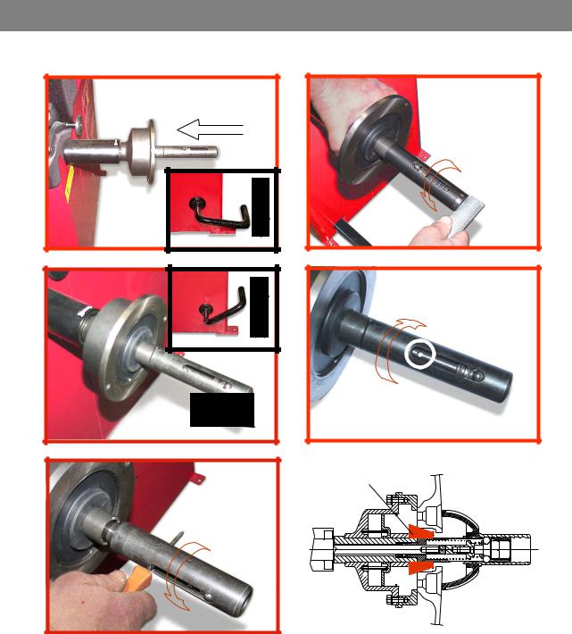
3.5 — ADAPTER MOUNTING
The balancing machine is supplied complete with cone adapter for fastening wheels with central bore. Other optional fl anges can be mounted once the terminal part is removed (also see enclosed brochures)
N.B. Carefully clean the coupling surfaces before performing any operation
a) DISMOUNTING THREADED END PIECE
A
a)Back-off screw B and remove threaded end-piece A.
b)Fit the new adapter
I 0307_0308 GB — 5
SE2-Dismounting
e
—Quando possibile, centrare le ruote con cono dall’interno (vedi disegno).
—Evitare di usare il manicotto RL con cerchi di ferro.
—Whenever possible, centre the wheels with the cone from the inside (see the drawing).
—Avoid using the RL sleeve with metal rims.
—Lorsque c’est possible, centrer les roues avec le cône de l’intérieur (voir dessin).
—Eviter d’utiliser le manchon RL avec les jantes en fer.
—Wenn möglich, die Räder mit Konus von Innen heraus zentrieren (siehe Zeichnung).
—Bei Eisenfelgen die Verwendung der Muffe RL vermeiden.
—Siempre que sea posible, centrar las ruedas con cono desde dentro (véase dibujo).
—Evitar usar el manguito RL con llantas de hierro.
SE2_ 0140

3.6 — GUARD MOUNTING AND ADJUSTMENT
a) Fasten the components to the base as illustrated in specifi c exploded view.
b) The position of the wheel guard when closed can be adjusted with relative screw accessible at the back. Correct position is the one which keeps the tube exactly horizontal with wheel guard closed.
c) Check that the microswitch is held down when the guard is closed. d) Adjust the angular position of microswitch control.
3.7 — SPACER WD
When balancing very wide wheels (9”), there is not enough space to turn the distance gauge. To withdraw the wheel from the machine side, fi t spacer WD on the adapter body and secure it with the standard issue nuts. When centring the wheel with the cone on the inside, fi t the spacer DC to obtain spring thrust.
|
Fig.4 |
|||||||||
|
DC |
WD |
||||||||
|
Spring |
Cone |
||||||||
4 — CONTROLS AND COMPONENTS
4.1 — BRAKE PEDAL
Fig.5
This pedal allows the operator to hold the wheel when fi tting the counterweights.
It must not be actuated during the measuring cycle.
|
4.2 — PNEUMATIC LOCKING PEDAL (Version P) |
|
|
Fig.6 |
This pedal allows releasing the device |
|
fastening the wheel on the adapter. |
|
|
Do not actuate this pedal during the |
|
|
machine cycle and/or when adapters |
|
|
other than the standard cone |
|
|
adapter are mounted. |
|
|
The pedal has two stable positions: |
|
|
top, wheel unclamped; bottom, |
|
|
wheel clamped |
I 0307_0308 GB — 8
4.3 — AUTOMATIC DISTANCE AND DIAMETER GAUGE
This gauge allows measurement of the distance of the wheel from the machine and the wheel diameter at the point of application of the counterweight.
It also allows correct positioning of the counterweights on the inside by using the specifi c function which allows reading the position used for the measurement within the rim.
The gauge can only be used with the counterweight pincers mounted.
4.4 — AUTOMATIC WIDTH GAUGE (OPTIONAL)
Width gauging is through a SONAR device which measures the distance of the wheel without mechanical contact, merely by closing the guard and each time a valid measurement has been made with gauge
DISTANCE AND DIAMETER GAUGE.
4.5 — AUTOMATIC WHEEL POSITIONING
At the end of the spin, the wheel is positioned according to the unbalance on the outside or else according to the static unbalance (when selected).
Precision is ± 20° for wheels up to 25 kg. in weight. Positioning is automatically disenabled for wheels of less than 13” in diameter.
I 0307_0308 GB — 9
Купить «Балансировочный стенд Cemb C72» в Москве и России
Балансировочный стенд Cemb C 72 используется для выявления и устранения дисбаланса на колесах малотоннажных грузовиков и разнообразных легковых автомобилей. С помощью стенка осуществляется микропроцессорная балансировка. Ввод двух из трех основных параметров колеса, которые необходимы в процессе выполнения работы, производится в автоматическом режиме. Ширина колеса замеряется с помощью системы Sonar, точность измерения которой составляет 0,5мм.
Применяется автоматическая остановка колес, диаметр диска которых не менее 13 дюймов, в положение «12 часов» со звуковым сигналом, чтобы можно было проще размещать балансировочные грузики. Колесо фиксируется при помощи мощных пневматических зажимов. Для экстренной остановки движения вала может быть применена педаль тормоза. Станок снабжен защитным кожухом, позволяющим оператору безопасно работать в зоне вращения колеса. При опускании этого кожуха происходит автозапуск станка.
Для балансировки алюминиевых дисков используются четыре программы. Есть программа ALUS, кроме того, имеются 3 программы для устранения статического дисбаланса. Возникающая погрешность точности производимых измерений не превышает 1 грамма. Осуществляется индикация чрезмерной вибрации. С помощью электронной измерительной линейки производится точная установка липких грузиков. Корректирующие грузики могут быть разделены. Статический дисбаланс минимизируется автоматически.