|
(495) 984-51-05 Москва |
Документация | Электроприводы переменного тока
Commander C200 | C300
Commander C200 | C300 — Руководство пользователя по управлению
Commander C200 | C300 — Руководство по установке электропитания | Габариты с 1 по 4
Commander C200 | C300 — Руководство по установке электропитания | Габариты с 5 по 6
Commander C200 | C300 — Руководство по установке электропитания | Габариты с 7 по 10
Commander C200 | C300 — Краткое руководство пользователя | Габариты с 1 по 4
Commander C200 | C300 — Краткое руководство пользователя | Габариты с 5 по 9
Commander C200 — Краткое руководство пользователя | Габариты с 1 по 4
Commander SK — Commander C200 — Брошюра
Commander C200 — Брошюра
Commander C200 — Справочное руководство по параметрам
Commander C300 — Справочное руководство по параметрам
Commander SK
Commander SK — Приступаем к работе (габариты 2 — 6) (pdf, 6286Kb)
Commander SK — Расширенное руководство пользователя (pdf, 5816Kb)
Commander SK — Брошюра (pdf, 8226Kb)
Commander SK — Datasheet size A (pdf, 300Kb)
Commander SK — Datasheet size B (pdf, 353Kb)
Commander SK — Datasheet size C (pdf, 552Kb)
Commander SK — Datasheet size D (pdf, 242Kb)
Commander SK — Технические характеристики (pdf, 8252Kb)
Руководство по замене Commander SE на Commander SK (pdf, 2167Kb)
Commander SK — Руководство пользователя (приступаем к работе, габариты 2 — 6) (pdf, 7523Kb)
Commander SK — Руководство пользователя (приступаем к работе, габариты A — D) (pdf, 1202Kb)
Commander SK — Руководство пользователя (все габариты) (pdf, 11299Kb)
Commander SE (устаревшая модель) — Руководство пользователя (pdf, 1216Kb)
Commander SE (устаревшая модель) — Расширенное руководство пользователя (pdf, 4557Kb)
Commander SE (устаревшая модель) — Брошюра (pdf, 582Kb)
Commander SX
Commander SX — Расширенное руководство пользователя (pdf, 2368Kb)
Commander SX — Брошюра (pdf, 234Kb)
Commander SX — Тормозной контактор (pdf, 137Kb)
Commander SX — Модуль тормозного контактора со входом защитного отключения (pdf, 179Kb)
Commander SX — Тормозной резистор (pdf, 542Kb)
Commander SX — Разводка кабелей (pdf, 604Kb)
Commander SX — Разъединитель (pdf, 675Kb)
Commander SX — Модуль подключения энкодера (pdf, 117Kb)
Commander SX — LCD (pdf, 259Kb)
Commander SX — Защита (pdf, 125Kb)
Commander SX — Руководство пользователя (pdf, 2488Kb)
Commander SX — Карта памяти (pdf, 154Kb)
Commander SX — Опции (pdf, 360Kb)
Unidrive SP
Unidrive SP — Брошюра (pdf, 5453Kb)
Unidrive SP — Руководство пользователя (pdf, 44584Kb)
Unidrive SP — Расширенное руководство пользователя (pdf, 10602Kb)
Unidrive SP — Брошюра по приводам шкафного исполнения от 90 до 675 кВт (pdf, 1806Kb)
Unidrive SPM — Руководство пользователя по модульным преобразователям (pdf, 28999Kb)
Unidrive SP — Руководство по использованию преобразователей для систем рекуперации энергии (pdf, 16382Kb)
Unidrive SP — Контроллер позиционирования APC (Advanced Position Controller) (pdf, 2035Kb)
Unidrive SPM — Брошюра по модульным приводам SPM (pdf, 2138Kb)
Руководство по замене Unidrive на Unidrive SP (pdf, 13641Kb)
Руководство по замене Unidrive SP на Unidrive M600 | M700 (pdf, 5054Kb)
Unidrive SPM — Руководство по модульным преобразователям (pdf, 23528Kb)
Unidrive SP — Брошюра 0-й габарит (pdf, 2174Kb)
Unidrive SP — Руководство по применению с лифтами (pdf, 7924Kb)
Commander GP (устаревшая модель) — Руководство пользователя (pdf, 2721Kb)
Unidrive SP — Расширенное руководство пользователя (pdf, 5891Kb)
Unidrive SP — Функция безопасного останова (pdf, 3830Kb)
Unidrive SP — Руководство пользователя для приводов шкафного исполнения (габариты 6 — 9) (pdf, 20409Kb)
Unidrive SP — Руководство по рекуперации энергии в сеть (pdf, 11208Kb)
Контроллер управления модулями SPM (pdf, 2685Kb)
Unidrive SP шкафного исполнения до 1600 кВт — Брошюра (pdf, 2825Kb)
Affinity
Affinity — Брошюра (pdf, 2033Kb)
Affinity — Руководство пользователя (pdf, 23139Kb)
Affinity — Расширенное руководство пользователя (pdf, 5416Kb)
Affinity — Руководство по настройке макросов (pdf, 616Kb)
Unidrive M
Unidrive M100
Unidrive M100 — Брошюра
Unidrive M100 — Руководство пользователя
Unidrive M100 — Краткое руководство пользователя
Unidrive M100 — M400 — Руководство по установке электропитания | Габариты с 1 по 4
Unidrive M — Руководство по установке электропитания | Габариты с 5 по 6
Unidrive M — Руководство по установке электропитания | Габариты с 7 по 10
Unidrive M200
Unidrive M200 — Брошюра
Unidrive M200 — Руководство пользователя
Unidrive M200 — Краткое руководство пользователя (габариты 1 — 4)
Unidrive M200 — Краткое руководство пользователя (габариты 5 — 6)
Unidrive M100 — M400 — Руководство по установке электропитания | Габариты с 1 по 4
Unidrive M — Руководство по установке электропитания | Габариты с 5 по 6
Unidrive M — Руководство по установке электропитания | Габариты с 7 по 10
Unidrive M300
Unidrive M300 — Брошюра
Unidrive M300 — Руководство пользователя
Unidrive M300 — Краткое руководство пользователя (габариты 1 — 4)
Unidrive M300 — Краткое руководство пользователя (габариты 5 — 6)
Unidrive M100 — M400 — Руководство по установке электропитания | Габариты с 1 по 4
Unidrive M — Руководство по установке электропитания | Габариты с 5 по 6
Unidrive M — Руководство по установке электропитания | Габариты с 7 по 10
Unidrive M400
Unidrive M400 — Брошюра
Unidrive M400 — Руководство пользователя
Unidrive M400 — Краткое руководство пользователя (габариты 1 — 4)
Unidrive M400 — Краткое руководство пользователя (габариты 5 — 
Unidrive M100 — M400 — Руководство по установке электропитания | Габариты с 1 по 4
Unidrive M — Руководство по установке электропитания | Габариты с 5 по 6
Unidrive M — Руководство по установке электропитания | Габариты с 7 по 10
Unidrive M600
Unidrive M600 — Брошюра
Unidrive M600 — Руководство пользователя
Unidrive M600 — Краткое руководство пользователя
Unidrive M — Руководство по установке электропитания | Габариты с 5 по 6
Unidrive M — Руководство по установке электропитания | Габариты с 7 по 10
Unidrive M700
Unidrive M700 | M701 — Брошюра
Unidrive M700 | M701 — Руководство пользователя
Unidrive M700 | M701 — Краткое руководство пользователя
Unidrive M — Руководство по установке электропитания | Габариты с 5 по 6
Unidrive M — Руководство по установке электропитания | Габариты с 7 по 10
Unidrive F300
Unidrive F300 — Брошюра
Unidrive F300 — Руководство пользователя
Unidrive F300 — Краткое руководство пользователя
|
Поддержка и помощь |
Продукция сертифицирована |
Доступность |
Сервисное обслуживание |
Оперативная доставка |
Данный сайт носит информационно-справочный характер и ни при каких условиях не является публичной офертой, которая определяется положениями Статьи 437 (2) Гражданского кодекса РФ.
- Manuals
- Brands
- Nidec Manuals
- DC Drives
- Commander C200
- Step-by-step manual
-
Contents
-
Table of Contents
-
Troubleshooting
-
Bookmarks
Quick Links
Commander C200/C300
Step By Step Guide
Guide pas à pas
Schritt-für-Schritt-Anleitung
Guida dettagliata
Guía detallada
Frame sizes 1 to 4
Tailles 1 à 4
Baugrößen 1 bis 4
Taglie da 1 a 4
Tamaños 1 a 4
Related Manuals for Nidec Commander C200
Summary of Contents for Nidec Commander C200
-
Page 1
Commander C200/C300 Step By Step Guide Guide pas à pas Schritt-für-Schritt-Anleitung Guida dettagliata Guía detallada Frame sizes 1 to 4 Tailles 1 à 4 Baugrößen 1 bis 4 Taglie da 1 a 4 Tamaños 1 a 4… -
Page 2: Features Of The Drive
English Introduction The Commander C200 and C300 is a simple and flexible range of drives from 0.25 kW to 132 kW in 9 frame sizes and three input voltage ranges (100 V, 200 V, and 400 V). This Step-by Step guide provides simple step-by-step instructions on how to mount the drive, fuse and cable selection, wiring the drive-up, programming the drive and running he motor in analog input mode or keypad mode on frames 1 to 4.
-
Page 3: Step 1: Check The Contents Of The Box
STEP 1: Check the contents of the box Check you have all the components and your drive has not been damaged during transportation. SAFETY KIT BAG INFORMATION CABLE BRACKET STEP BY STEP GUIDE STEP 2: Check model and voltage The model number can be found on the identification label on the top of the drive.
-
Page 4
A Drill template for wall mounting is included on the drive packaging (shown below). Alternativly refer to he table below for the mounting and overall dimensions. Frame Weight Ø Mounting Overall Mounting Overall Overall Diameter 143 mm 160 mm 53 mm 75 mm 130 mm 5 mm… -
Page 5
STEP 4: Select supply / motor cables and fuses or MCB The supply/motor cables and fuses or MCB’s used should follow he ratings provided in the table below: The voltage rating of fuses and MCBs must be greater than or equal to the highest supply voltage of the system. -
Page 6: Step 5: Remove The Terminal Cover
STEP 5: Remove the terminal cover Using a flat bladed screwdriver, turn the terminal cover locking clip anti-clockwise by approximately 30°. Slide the terminal cover down. Remove terminal cover in direction shown. STEP 6: Wire the drive up Power connections When wiring the drive the power, ground and control connections, they should be ightened to the recommended torque settings shown in the table below: Table 6-1 Recommended torque settings…
-
Page 7: Ground Connections
Ground connections The supply and motor ground connections are made using the ground busbar located at the bottom of the drive as shown in Figure 6-2. Electrochemical corrosion of grounding terminals Ensure hat grounding terminals are protected against corrosion i.e. as could be caused by condensation.
-
Page 8: Control Connections
Control connections The control terminals are configured by default for he arrangement shown below: Figure 6-3 Commander C200/C300 control terminal connections Digital I/O Analog I/O 24 V user Analog input 1 Digital I/O1 Frequency Zero frequency 10 kW reference 1…
-
Page 9: Step 7: Use The Keypad
STEP 7: Use the keypad The display provides information to he user regarding the operating status of the drive, alarms and trip code. The keypad provides the means for changing parameters, stopping and starting the drive, and the ability to perform a drive reset.
-
Page 10: Step 8: Run The Motor
STEP 8: Run the motor This step will provide instruction on how to set-up the basic drive parameters, perform an auto-tune and run the motor in analog input terminal mode or keypad mode. Action Detail Power Up Ensure: • The drive displays: inh (Enable terminal(s) is open) Minimum and Enter: maximum speed…
-
Page 11: Additional Information Troubleshooting
Additional Information Troubleshooting When the drive detects a fault it will display an error code. To locate and solve all error codes, a ‘Diagnostic Tool (App)’ is available on Microsoft, Android and iOS platform via the ‘Apps’ store on Smartphone / Tablet, search for ‘Control Techniques diagnostics tool in the Apps store’.
-
Page 12: Appendix A Ul Listing Information
Appendix A UL listing information This addendum provides additional information requested by UL to be supplied with the product. UL file reference All models are UL Listed to both Canadian and US requirements. The UL file reference is: NMMS/7.E171230. Products that incorporate the Safe Torque Off function have been investigated by UL. The UL file reference is: FSPC.E171230.
-
Page 13: Motor Overload Protection And Thermal Memory Retention
National Electrical Code (NEC), The Canadian Electrical Code, and any additional local codes. DYNAMIC BRAKING Commander C200/C300, frame sizes 1 to 4 have been evaluated for dynamic braking applications. Other drive models have not been evaluated for dynamic braking. Motor overload protection and thermal memory retention The devices incorporate solid state overload protection for the motor load.
-
Page 1
User Guide Free Standing Model sizes 6 to 9 Universal Variable Speed AC Drive for induction and servo motors Part Number: 0471-0122-01 Issue: 1 www.controltechniques.com… -
Page 2
General Information The manufacturer accepts no liability for any consequences resulting from inappropriate, negligent or incorrect installation or adjustment of the optional operating parameters of the equipment or from mismatching the variable speed drive with the motor. The contents of this guide are believed to be correct at the time of printing. In the interests of a commitment to a policy of continuous development and improvement, the manufacturer reserves the right to change the specification of the product or its performance, or the contents of the guide, without notice. -
Page 3
How to use this guide This user guide provides complete information for installing and operating the drive from start to finish. The information is in logical order, taking the reader from receiving the drive through to fine tuning the performance. NOTE There are specific safety warnings throughout this guide, located in the relevant sections. -
Page 4: Table Of Contents
4.13 SAFE TORQUE OFF (SECURE DISABLE) ..69 10.4 Getting started ……….126 10.5 Onboard PLC parameters …….. 126 10.6 Onboard PLC trips ……….. 127 10.7 Onboard PLC and the SMARTCARD ….127 Unidrive SP Free Standing User Guide www.controltechniques.com Issue Number: 1…
-
Page 5: Table 2-1 400V Standard (Ip21) Free Standing Drive Table
14.3 AC supply specification ……..260 14.4 Maximum continuous output current ….260 14.5 Safety label …………260 14.6 UL listed accessories ……..260 List of figures ……..261 List of tables ……..263 Index ………..265 Unidrive SP Free Standing User Guide Issue Number: 1 www.controltechniques.com…
-
Page 6
*Clause 5.2.3.8 of EN 61800-5-1:2003 (breakdown of components test) has been amended to eliminate the 30A ground (earth) fuse, in accordance with the draft edition 2 of IEC 61800-5-1 Unidrive SP Free Standing User Guide www.controltechniques.com Issue Number: 1… -
Page 7: Safety Information
The system designer is responsible for ensuring that the complete system is safe and designed correctly according to the relevant safety standards. Independent approval by BGIA has been given. Unidrive SP Free Standing User Guide Issue Number: 1 www.controltechniques.com…
-
Page 8: Product Information
Information Product information Unidrive SP Free Standing cubicles are made up to one or more SPM modules (SPMA / SPM), depending on size and current ratings. Model number The way in which the model numbers for the Unidrive SP range are formed is illustrated below.
-
Page 9: Ratings
Data Information Ratings The Unidrive SP is dual rated. Available output The setting of the motor rated current determines which rating applies — Overload limit — current Heavy Duty Heavy Duty or Normal Duty. Maximum The two ratings are compatible with motors designed to IEC60034.
-
Page 10
690V 575V current current 690V 575V current current 66X1 66X2 76X1 76X2 5 6 5 7 5 8 86X1 86X2 86X3 86X4 96X1 96X3 96X4 96X5 Unidrive SP Free Standing User Guide www.controltechniques.com Issue Number: 1… -
Page 11: Table 2-3 400V Ip23 Free Standing Drive Ratings At
76X2-E23 5 6 5 7 5 8 86X1-E23 86X2-E23 86X3-E23 86X4-E23 96X1-E23 96X3-E23 96X4-E23* 96X5-E23* * Ratings for SP96X4 E23 and SP96X5 E23 are for an ambient temperature of 30°C Unidrive SP Free Standing User Guide Issue Number: 1 www.controltechniques.com…
-
Page 12: Operating Modes
2.3.4 Servo For use with permanent magnet brushless motors with a feedback The Unidrive SP is designed to operate in any of the following modes: device installed. 1. Open loop mode The drive directly controls the speed of the motor using the feedback Open loop vector mode device to ensure the rotor speed is exactly as demanded.
-
Page 13: Drive Features
3 Control terminals Encoder connection Relay terminals Braking terminals (optional) Motor Motor connections connections Ground connections Ground connections Braking terminals (optional) AC supply connections Internal fuse location Internal fuse location Unidrive SP Free Standing User Guide Issue Number: 1 www.controltechniques.com…
-
Page 14: Figure 2-5 Features Of The Size 8 And 9 Free Standing
Relay terminals Brake connections (optional) Brake connections (optional) Motor connections Motor connections 24V power supply Ground connections AC supply connections AC supply connections Internal fuse Internal fuse location location Unidrive SP Free Standing User Guide www.controltechniques.com Issue Number: 1…
-
Page 15: Nameplate Description
Heavy Duty / No. of phases & frequency Normal Duty Typical input current for rating output current Normal Duty rating Options Figure 2-7 Options available with Unidrive SP SMARTCARD* Keypad Feedback Automation Fieldbus CT Comms cable * A SMARTCARD is provided as standard. For further information, refer to Chapter 9 SMARTCARD operation on page 119.
-
Page 16: Table 2-7 Solutions Module Identification
Additional I/O with overvoltage protection up to 48V SM-I/O 24V Cobalt Blue 2 x Analog outputs (current modes) Protected 4 x Digital input / outputs, 3 x Digital inputs, 2 x Relay outputs Unidrive SP Free Standing User Guide www.controltechniques.com Issue Number: 1…
-
Page 17
Pale Green SM-LON LonWorks adapter for communications with the drive SLM interface The SM-SLM allows SLM feedback to be connected directly to the Unidrive SP drive and allows operation in either of the Orange SM-SLM following modes: • Encoder only mode •… -
Page 18: Items Supplied With The Drive
The drive is supplied with a printed manual, a SMARTCARD, a safety information booklet, the Certificate of Quality, and a CD ROM containing all related product documentation and software tools. All accessories (e.g. control connectors) are supplied installed to the drive. Unidrive SP Free Standing User Guide www.controltechniques.com Issue Number: 1…
-
Page 19: Mechanical Installation
Lift the drive by the method detailed in Figure 3-2 on page 20. Do not tilt the drive. The centre of gravity of the unit is high. An overturning unit can cause physical injury. Unidrive SP Free Standing User Guide Issue Number: 1 www.controltechniques.com…
-
Page 20: Planning The Installation
0.5 metres must be maintained between drives. Certain Unidrive SP size 6 and 7 Free Standing drives are fitted with smaller roof fans, baffling should also be fitted if installed side by side Unidrive SP Free Standing User Guide www.controltechniques.com…
-
Page 21: Figure 3-3 Location And Identification Of Terminal Covers For Free Standing Drives
Data Information Figure 3-3 Location and identification of terminal covers for Free Standing drives Control Control Input / output Input / output Input / output Unidrive SP Free Standing User Guide Issue Number: 1 www.controltechniques.com…
-
Page 22: Figure 3-4 Removing The Size 6, 7 And 8 Terminal Covers From The Free Standing Drive
Started parameters the motor operation parameters Data Information Figure 3-4 Removing the size 6, 7 and 8 terminal covers from the Free Standing drive Pozi Pz4 Pozi Pz2 Pozi Pz4 Unidrive SP Free Standing User Guide www.controltechniques.com Issue Number: 1…
-
Page 23: Figure 3-5 Removing The Size 9 Terminal Covers From The Free Standing Drive
Installation Started parameters the motor operation parameters Data Information Figure 3-5 Removing the size 9 terminal covers from the Free Standing drive Pozi Pz4 Pozi Pz2 Pozi Pz4 Pozi Pz4 Unidrive SP Free Standing User Guide Issue Number: 1 www.controltechniques.com…
-
Page 24: Installing Fuses In A Free Standing Drive
3.4.2 Size 8 & 9 (with date code S18 or later) Secure fuse to upper Unidrive SP size 8 and 9 Free Standing with date code of S18 or later mounting stud with M10 nut can accept type DIN80 or type DIN110 fuses.
-
Page 25: Figure 3-10 Preparation For Baying The Incomer/Applications Shell
Data Information Figure 3-10 Preparation for baying the incomer/applications shell An incomer shell is supplied with no side panels. Figure 3-11 Preparation for baying the size 8 Free Standing drive Unidrive SP Free Standing User Guide Issue Number: 1 www.controltechniques.com…
-
Page 26: Figure 3-12 Preparation For Baying The Size 9 Free Standing Drive (Slave And Master)
Lift the drive by the method detailed in Figure 3-2 on page 20. Do not tilt the drive. The centre of gravity of the unit is high. WARNING An overturning unit can cause physical injury. Unidrive SP Free Standing User Guide www.controltechniques.com Issue Number: 1…
-
Page 27: Figure 3-13 Location Of The Rectifier Status Connectors For Size 9 Free Standing Drive
2. M6 star lock washer 3. In comer frame Free Standing drive frame 5. M6 screw Once the Free Standing drive and incomer are in position they must be bolted to the floor Unidrive SP Free Standing User Guide Issue Number: 1 www.controltechniques.com…
-
Page 28: Figure 3-15 Installing The Parallel Cable From A Size 9 Master To Slave
1. Remove size 9 slave interface cover 2. Connect the paralleling cable to the size 9 slave input slot 3. Replace size 9 slave interface cover 4. Replace all size 9 Free Standing drive panels Unidrive SP Free Standing User Guide www.controltechniques.com Issue Number: 1…
-
Page 29: Figure 3-16 Input Busbar Connections Between The
Fit the input parallel busbar with (M8 x 20 screws) (torque 17Nm [12.5 lb ft]); and M6 x 30 insulating spacer with (M6 x 12 screws) (torque 12Nm [8.85 lb ft]) Fit the input parallel busbar with (M8 x 20 screws) (torque 17Nm [12.5 lb ft]) Unidrive SP Free Standing User Guide Issue Number: 1 www.controltechniques.com…
-
Page 30: Figure 3-17 Input Busbar Connections Between The
4. Fit: 2 x 12 pulse busbars, 4 x 30mm insulator, 6 x M6x16 screws, 4 x M8x20 screws, L1(A) terminal marker NOTE Pre-fit insulators to busbars before fitting to cubicle. Unidrive SP Free Standing User Guide www.controltechniques.com Issue Number: 1…
-
Page 31: Figure 3-18 Baying A 6 Pulse Incomer To A 6 Pulse Free Standing Drive (Size 8 Shown)
The images below shows how to remove the gland plate from a Free Standing drive. Figure 3-19 Removing the cable gland plate from the Free Standing drive for «glanding off» the cable Unidrive SP Free Standing User Guide Issue Number: 1…
-
Page 32: Free Standing Drive Dimensions
Data Information Free standing drive dimensions Figure 3-20 Incomer/applications shell dimensions 400mm 600mm (15.748in) (23.622in) ∅20mm (0.787in) 520mm 600mm (20.472in) (23.622in) 315mm (12.402in) 404.6mm (15.929in) Unidrive SP Free Standing User Guide www.controltechniques.com Issue Number: 1…
-
Page 33: Figure 3-21 Size 6 And 7 Drives With Integral Line Side
Started parameters the motor operation parameters Data Information Figure 3-21 Size 6 and 7 drives with integral line side options 400mm 630mm (15.75in) (24.80in) ∅20mm (0.79in) 315mm (12.40in) 404.6mm (15.93in) Unidrive SP Free Standing User Guide Issue Number: 1 www.controltechniques.com…
-
Page 34: Figure 3-22 Size 6, 7 And 8 Free Standing Drive Dimensions
Dimensions for IP23 drives are:- H — 2248.5 mm (88.521 in) D — 653 mm (25.70 in) W =- 404.6 mm (15.929 in) 520mm 600mm (20.472in) (23.622in) 315mm (12.402in) 404.6mm (15.929in) Unidrive SP Free Standing User Guide www.controltechniques.com Issue Number: 1…
-
Page 35: Figure 3-23 Size 9 Free Standing Drive Dimensions
Dimensions for IP23 drives are:- H — 2248.5 mm (88.521 in) D — 653 mm (25.70 in) W — 809.2 mm (31.85 in) 520mm 600mm (20.472in) (23.622in) 89.60mm (3.528in) 719.60mm (28.331in) 809.20mm (31.858in) Unidrive SP Free Standing User Guide Issue Number: 1 www.controltechniques.com…
-
Page 36: External Emc Filter
28 kg (61.7 lb) SP96X5 4200-6814 18 kg (39.7 lb) 4200-6807 28 kg (61.7 lb) NOTE Contact the supplier of the drive for information on EMC filters for 12 pulse drives. Unidrive SP Free Standing User Guide www.controltechniques.com Issue Number: 1…
-
Page 37: Figure 3-24 Size 6 , 7, 8 And 9 Epcos External Emc Filter
42±3 mm 4200 — 6806 260 mm 116 mm 434±3 mm Ø11 350 mm 145±0.5 mm 4200 — 6807 80 mm 275 mm 3 mm 52±3 mm 454±3 mm Ø14 Unidrive SP Free Standing User Guide Issue Number: 1 www.controltechniques.com…
-
Page 38: Figure 3-25 Size 8 And 9 Schaffner External Emc Filter
145±1 mm 280±1 mm 255 mm 50 mm 177 mm 450 mm 4200-6814 3 mm Ø14 4200-6810 400±1 mm 170±1 mm 300±1 mm 275 mm 90 mm 160 mm 580 mm Unidrive SP Free Standing User Guide www.controltechniques.com Issue Number: 1…
-
Page 39: Electrical Terminals
Input terminals M10 nut Internal fuse 17mm AF location M10 nut Internal fuse 17mm AF location M10 nut Input terminals 17mm AF M10 nut 17mm AF Unidrive SP Free Standing User Guide Issue Number: 1 www.controltechniques.com…
-
Page 40: Figure 3-27 Locations Of The Power And Ground Terminals
17mm AF terminals M10 nut 17mm AF Ground stud Ground stud Input busbar 10.5mm Input busbar 10.5mm Internal fuse location M10 nut Internal fuse 17mm AF location M10 nut 17mm AF Unidrive SP Free Standing User Guide www.controltechniques.com Issue Number: 1…
-
Page 41: Table 3-5 Drive Control And Relay Terminal Data
Max torque 4200-6808 48 N m 4200-6811 48 N m 4200-6812 48 N m 4200-6813 48 N m 4200-6809 83 N m 4200-6814 83 N m 4200-6810 83 N m Unidrive SP Free Standing User Guide Issue Number: 1 www.controltechniques.com…
-
Page 42: Solutions Module Installation / Removal
To remove, while pressing the tabs inwards (A), gently lift the keypad in the direction indicated (B). NOTE The keypad can be installed / removed while the drive is powered up and running a motor, providing that the drive is not operating in keypad mode. Unidrive SP Free Standing User Guide www.controltechniques.com Issue Number: 1…
-
Page 43: Routine Maintenance
Ensure all screw terminals remain tight Ensure all crimp terminals remains tight – check for any discoloration which could indicate Crimp terminals overheating Cables Check all cables for signs of damage Unidrive SP Free Standing User Guide Issue Number: 1 www.controltechniques.com…
-
Page 44: Electrical Installation
If the motor load is capable of rotating the motor when the supply is disconnected, then the motor must be isolated from the drive before gaining access to any live parts. Unidrive SP Free Standing User Guide www.controltechniques.com Issue Number: 1…
-
Page 45: Power Connections
Started parameters the motor operation parameters Data Information Power connections 4.1.1 AC and DC connections Figure 4-1 Unidrive SP size 6 Free Standing drive power connections Optional (SPxx1x brake versions only) Thermal overload protection device Motor Optional ground connection Output connections…
-
Page 46: Figure 4-2 Unidrive Sp Size 7 Free Standing Drive Power Connections
Information information Installation Installation Started parameters the motor operation parameters Data Information Figure 4-2 Unidrive SP size 7 Free Standing drive power connections Optional (SP7x1x brake versions only) Thermal overload protection device Motor Optional ground connection Output connections Input connections…
-
Page 47: Figure 4-3 Unidrive Sp Size 8 Free Standing Drive Power Connections
Information information Installation Installation Started parameters the motor operation parameters Data Information Figure 4-3 Unidrive SP size 8 Free Standing drive power connections Per cubicle (SP8x1x brake versions only) Thermal Thermal overload overload protection protection device device Motor Optional ground…
-
Page 48: Figure 4-4 Unidrive Sp Size 9 Free Standing Drive Power Connections
Installation Installation Started parameters the motor operation parameters Data Information Figure 4-4 Unidrive SP size 9 Free Standing drive power connections Per cubicle (SP9x1x brake versions only) Thermal Thermal overload overload protection protection device device Both motor cables must be the same length.
-
Page 49: Figure 4-5 Unidrive Sp Size 6 And 7 Free Standing Drive Ground Connections
Data Information 4.1.2 Ground connections Figure 4-6 Unidrive SP size 8 and 9 Free Standing drive ground connections Figure 4-5 Unidrive SP size 6 and 7 Free Standing drive ground connections Ground Ground connections connections The ground loop impedance must conform to the requirements of local safety regulations.
-
Page 50: Ac Supply Requirements
3.5% negative phase sequence (equivalent to 5% voltage imbalance between phases). Severe disturbances may be caused by the following factors, for example: • Power factor correction equipment connected close to the drive. Unidrive SP Free Standing User Guide www.controltechniques.com Issue Number: 1…
-
Page 51: Auxiliary Power Supply
For all size 6 & 7, and size 8 & 9 units that have a date code of R48 and later, a mains transformer has been introduced for Unidrive SP 8XXX and 9XXX Free Standing drives. The new transformer eliminates the requirement for a separate external 230V power source.
-
Page 52: Figure 4-9 Location Of Size 8 And 9 Free Standing Drive Mains Transformer
Until the cable is moved from the parked position to the terminals identified above, the drive will not power up using the three phase supply. The ground and 0V wires are also pre-fitted and must not be changed. Unidrive SP Free Standing User Guide www.controltechniques.com…
-
Page 53: Control 24Vdc Supply
Data Information Control 24Vdc supply The 24Vdc input on the Unidrive SP has three main functions. • It can be used to supplement the drive’s own internal 24V when multiple SM-Universal Encoder Plus, SM-Encoder Output Plus or SM-I/O Plus or SM-I/O32 modules are being used, and the current drawn by these modules is greater than the drive can supply.
-
Page 54: Table 4-3 400V Free Standing Drive Input Current, Fuse And Cable Size Rating
The Semiconductor IEC class aR fuses for sizes 6, 7, 8 and 9 drives must be installed within the enclosure, see Figure on page 24. These parts may be purchased from Control Techniques, see Table 4-5. Unidrive SP Free Standing User Guide www.controltechniques.com Issue Number: 1…
-
Page 55: Table 4-5 Fuses
To ensure that the motor and cable are protected against overload, the drive must be programmed with the correct motor rated current. Unidrive SP Free Standing User Guide Issue Number: 1 www.controltechniques.com…
-
Page 56: Output Circuit And Motor Protection
This is because of the high rate of change of voltage, in conjunction with the impedance of the motor cable and the distributed nature of the motor winding. Unidrive SP Free Standing User Guide www.controltechniques.com Issue Number: 1…
-
Page 57: Figure 4-11 Preferred Chain Connection For Multiple Motors
The Drive Enable terminal (T31) when opened provides a SECURE DISABLE function. This can in many cases replace output contactors. For further information see section 4.13 SAFE TORQUE OFF (SECURE DISABLE) on page 69. Unidrive SP Free Standing User Guide Issue Number: 1 www.controltechniques.com…
-
Page 58: Braking
Optimization of the braking resistor requires a careful consideration of the braking duty. Unidrive SP Free Standing User Guide www.controltechniques.com Issue Number: 1…
-
Page 59: Ground Leakage
Braking resistor software overload protection WARNING The Unidrive SP software contains an overload protection function for a If an external EMC filter is used, a delay of at least 50ms should be braking resistor. In order to enable and set-up this function, it is incorporated to ensure spurious trips are not seen.
-
Page 60: Figure 4-14 Installation Of Grounding Bracket (Master/Slave)
In these cases all the shields should be connected to ground and 0V at both ends. Unidrive SP Free Standing User Guide www.controltechniques.com Issue Number: 1…
-
Page 61: Figure 4-15 Feedback Cable, Twisted Pair
4.9.3 Compliance with EN 61800-3 (standard for Power Drive Systems) Meeting the requirements of this standard depends on the environment that the drive is intended to operate in, as follows: Unidrive SP Free Standing User Guide Issue Number: 1 www.controltechniques.com…
-
Page 62: Figure 4-17 Connecting The Motor Cable To An Isolator / Disconnect Switch
Figure 4-18 Surge suppression for digital and unipolar inputs and outputs Signal from plant Signal to drive 30V zener diode e.g. 2xBZW50-15 Figure 4-19 Surge suppression for analog and bipolar inputs and Unidrive SP Free Standing User Guide www.controltechniques.com Issue Number: 1…
-
Page 63: Serial Communications Connections
Serial communications connections 4.10.2 Multi-drop network The Unidrive SP can be used on a 2 wire EIA485 multi-drop network The Unidrive SP has a serial communications port (serial port) as using the drive’s serial communications port when the following standard supporting 2 wire EIA485 communications. Please see Table guidelines are adhered to.
-
Page 64: Figure 4-21 Default Terminal Functions
Ensure the logic sense is correct for the control circuit to be Connections for used. Incorrect logic sense could cause the motor to be differential input signal started unexpectedly. Positive logic is the default state for Unidrive SP. CAUTION Analog frequency/speed NOTE reference 2 Any signal cables which are carried inside the motor cable (i.e.
-
Page 65
T8 analog input 3 has a parallel connection to terminal 15 of the drive encoder connector. Unidrive SP Free Standing User Guide Issue Number: 1 www.controltechniques.com… -
Page 66
Maximum output current 240mA (including all digital I/O) 0V common Protection Current limit and trip Common connection for all external Function devices 0V common Common connection for all external Function devices Unidrive SP Free Standing User Guide www.controltechniques.com Issue Number: 1… -
Page 67: Encoder Connections
The UVW commutation signals are used to define the motor position during the first 120° electrical rotation after the drive is powered-up or the encoder is initialized. Unidrive SP Free Standing User Guide Issue Number: 1 www.controltechniques.com…
-
Page 68: Table 4-14 Drive Encoder Connector Details
Line loading <2 unit loads Ω Line termination components (switchable) Working common mode range +12V to –7V Absolute maximum applied voltage ±25V relative to 0V Absolute maximum applied differential ±25V voltage Unidrive SP Free Standing User Guide www.controltechniques.com Issue Number: 1…
-
Page 69: Safe Torque Off (Secure Disable)
±4V ±14V and common mode voltage range relative to 0V For the SinCos encoder to be compatible with Unidrive SP, the output Absolute maximum applied differential ±14V voltage signals from the encoder must be a 1V peak to peak differential voltage (across Sin to Sinref and Cos to Cosref).
-
Page 70: Figure 4-23 Start / Stop Control En954-1 Category
SAFE TORQUE OFF (SECURE DISABLE) does not provide electrical isolation. The supply to the drive must be disconnected by an approved isolation device before gaining access to power connections. WARNING Unidrive SP Free Standing User Guide www.controltechniques.com Issue Number: 1…
-
Page 71: Figure 4-25 Category 3 Interlock Using Safe Torque
The auxiliary relay K2 must be located in the same enclosure and close to the drive, with its coil connected as closely as possible to the drive enable / SAFE TORQUE OFF (SECURE DISABLE) input. Unidrive SP Free Standing User Guide Issue Number: 1 www.controltechniques.com…
-
Page 72: Getting Started
Understanding the display There are two keypads available for the Unidrive SP. The SM-Keypad has an LED display and the SM-Keypad Plus has an LCD display. Both keypads can be installed on the drive but the SM-Keypad Plus can also be remotely mounted on an enclosure door.
-
Page 73: Menu Structure
NOTE For new parameter-values to apply after the AC supply to the drive is interrupted, new values must be saved. Refer to section 5.7 Saving parameters on page 76. Unidrive SP Free Standing User Guide Issue Number: 1 www.controltechniques.com…
-
Page 74: Menu 0
Appropriate parameters are copied from the advanced menus into menu 0 and thus exist in both locations. For further information, refer to Chapter 6 Basic parameters on page 80. Unidrive SP Free Standing User Guide www.controltechniques.com Issue Number: 1…
-
Page 75: Advanced Menus
41.51 Browsing favourites control Normal (0), Filter (1) PLC registers PLC registers PLC registers PLC registers PLC registers Timer function parameters Digital I/O parameters Status parameters General parameters Fast access parameters Unidrive SP Free Standing User Guide Issue Number: 1 www.controltechniques.com…
-
Page 76: Changing The Operating Mode
1. Ensure the drive is not enabled, i.e. terminal 31 is open or Pr 6.15 is Off (0) 2. Enter 1233 (EUR 50Hz settings) or 1244 (USA 60Hz settings) in Pr xx.00. Unidrive SP Free Standing User Guide www.controltechniques.com Issue Number: 1…
-
Page 77: Parameter Access Level And Security
If an incorrect security code is entered the display will revert to parameter view mode. To lock the User Security again, set Pr 0.49 to Loc and press the reset button. Unidrive SP Free Standing User Guide Issue Number: 1 www.controltechniques.com…
-
Page 78: Displaying Parameters With Non-Default Values Only
CT EIA232 Comms cable (CT Part No. 4500-0087) When using one of the above converters or any other suitable converter with the Unidrive SP, it is recommended that no terminating resistors be 0 to 247 connected on the network. It may be necessary to ‘link out’ the terminating resistor within the converter depending on which type is Used to define the unique address for the drive for the serial interface.
-
Page 79
9. Therefore, Pr 0.37 is limited to 99 in this mode. The value 00 is used to globally address all slaves on the system, and x0 is used to address all slaves of group x, therefore these addresses should not be set in this parameter. Unidrive SP Free Standing User Guide Issue Number: 1 www.controltechniques.com… -
Page 80: Basic Parameters
CL> Drive encoder lines per { 3.34 } 0 to 50,000 1024 4096 RW Uni revolution 0.28 Keypad fwd/rev key enable { 6.13 } OFF (0) or On (1) OFF (0) RW Bit Unidrive SP Free Standing User Guide www.controltechniques.com Issue Number: 1…
-
Page 81
V01.08.00 and later, power-down save Destination: This parameter selects the destination of an parameters are also saved in the drive when the user input or logic function. initiates a parameter save. Unidrive SP Free Standing User Guide Issue Number: 1 www.controltechniques.com… -
Page 82: Figure 6-1 Menu 0 Logic Diagram
A2.Pr Preset reference selectors Preset reference selectors Local/Remote Local/Remote Input Read-write (RW) 0.XX terminals parameter Read-only (RO) Output 0.XX parameter terminals The parameters are all shown in their default settings Unidrive SP Free Standing User Guide www.controltechniques.com Issue Number: 1…
-
Page 83
Drive output Drive encoder 0.11 0.27 frequency Overspeed 0.26 threshold OL & VT> Total motor Motor active current current 0.13 0.12 Magnetising 15 way sub-D current connector Resistor optional Unidrive SP Free Standing User Guide Issue Number: 1 www.controltechniques.com… -
Page 84: Full Descriptions
The drive speed reference is scaled between Pr 0.01 and Pr 0.02. [0.01] is a nominal value; slip compensation may cause the actual frequency to be higher. Unidrive SP Free Standing User Guide www.controltechniques.com Issue Number: 1…
-
Page 85
There are six voltage modes available, which fall into two categories, vector control and fixed boost. For further details, refer to section Pr 0.07 {5.14} Voltage mode on page 107. Unidrive SP Free Standing User Guide Issue Number: 1 www.controltechniques.com… -
Page 86: Figure 6-2 Fixed And Variable V/F Characteristics
0 to 65,535 ths of a revolution Servo Pr 0.11 displays the position of the encoder in mechanical values of 0 to 65,535. There are 65,536 units to one mechanical revolution. Unidrive SP Free Standing User Guide www.controltechniques.com Issue Number: 1…
-
Page 87
In modes 2 & 3 a current loop loss trip is generated if the current falls below 3mA. In modes 2 & 4 the analog input level goes to 0.0% if the input current falls below 4mA. Unidrive SP Free Standing User Guide Issue Number: 1 www.controltechniques.com… -
Page 88
Pr 0.22 determines whether the reference is uni-polar or bi-polar as 0 to 50,000 follows: 4096 Pr 0.22 Function Closed-loop Enter in Pr 0.27 the number of lines per revolution of the drive encoder. Unipolar speed/frequency reference Bipolar speed/frequency reference Unidrive SP Free Standing User Guide www.controltechniques.com Issue Number: 1… -
Page 89
Restrictions may be placed on bits, 1 stop bit and even parity; Modbus RTU uses 8 data bits, 2 stops the frequencies detected by the drive as follows: bits and no parity.) Unidrive SP Free Standing User Guide Issue Number: 1 www.controltechniques.com… -
Page 90
A rotating autotune first performs a stationary autotune, before rotating the motor at base speed in the forward direction for approximately 30 seconds. The motor must be free from load for the rotating autotune. Unidrive SP Free Standing User Guide www.controltechniques.com Issue Number: 1… -
Page 91
The full range of switching frequencies is not available on all ratings of (i.e. up to 2 mechanical revolutions) in the forward direction, and Unidrive SP. See section 8.5 Switching frequency on page 117, for the measure the encoder phase angle. The motor must be free from maximum available switching frequency for each drive rating. -
Page 92
0.00 to 40,000.00 rpm USA> 1,770.00 Open-loop This is the speed at which the motor would rotate when supplied with its base frequency at rated voltage, under rated load conditions (= Unidrive SP Free Standing User Guide www.controltechniques.com Issue Number: 1… -
Page 93
Each bit in this parameter has the following functions: Function Stop on non-important trips Disable braking IGBT trips Disable phase loss trip (Unidrive SP size 0 only) Disable braking resistor temperature monitoring failure detection. (Unidrive SP size 0 only) Stop on non-important trips If bit 0 is set to zero then the drive simply trips when a non-important trip occurs. -
Page 94: Running The Motor
Incremental encoder with forward and reverse outputs (F, R with or without Z) • SINCOS encoder (with, or without Stegmann Hiperface, EnDat or SSI communications protocols) • EnDat absolute encoder Unidrive SP Free Standing User Guide www.controltechniques.com Issue Number: 1…
-
Page 95
Safety Mechanical SMARTCARD Onboard Advanced Technical UL Listing Product Electrical Getting Basic Running Optimization Diagnostics Information information Installation Installation Started parameters the motor operation parameters Data Information Unidrive SP Free Standing User Guide Issue Number: 1 www.controltechniques.com… -
Page 96: Figure 7-1 Minimum Connections To Get The Motor Running In Any Operating Mode
Drive 0V open at encoder end Thermal overload for braking resistor to protect against fire risk. This must be wired to interrupt the AC supply in the event of a fault. Unidrive SP Free Standing User Guide www.controltechniques.com Issue Number: 1…
-
Page 97
Data Information +10V Speed reference input RUN FWD RUN REV DRIVE ENABLE L1 L2 L3 SM-Keypad / SM-Keypad Plus. 0.05 Optional item; must be fitted for keypad mode. =PAd (4) Unidrive SP Free Standing User Guide Issue Number: 1 www.controltechniques.com… -
Page 98: Quick Start Commissioning/Start-Up
Enter 1000 in Pr xx.00 Save parameters Press the red reset button or toggle the reset digital input (ensure Pr xx.00 returns to 0) Drive is now ready to run Unidrive SP Free Standing User Guide www.controltechniques.com Issue Number: 1…
-
Page 99
Enter 1000 in Pr xx.00 Save parameters Press the red reset button or toggle the reset digital input (ensure Pr xx.00 returns to 0) Drive is now ready to run Unidrive SP Free Standing User Guide Issue Number: 1 www.controltechniques.com… -
Page 100
0.03 0.04 Unidrive SP is able to perform either a stationary or a rotating autotune. The motor must be at a standstill before an autotune is enabled. A stationary autotune will give moderate performance whereas a rotating autotune will give improved performance as it measures the actual values of the motor parameters required by the drive. -
Page 101
0.04 Unidrive SP is able to perform a short low speed, a normal low speed or a minimal movement autotune. The motor must be at a standstill before an autotune is enabled. A normal low speed autotune will measure the encoder phase offset angle and calculate the current gains. -
Page 102: Quick Start Commissioning/Start-Up (Ctsoft)
Setting up a feedback device This section shows the parameter settings which must be made to use each of the compatible encoder types with Unidrive SP. For more information on the parameters listed here please refer to the Unidrive SP Advanced User Guide.
-
Page 103
Termination resistors must be enabled for wire break detection to operate * These settings should only be used in closed loop vector mode, otherwise a phase offset test must be performed after every power up. Unidrive SP Free Standing User Guide Issue Number: 1… -
Page 104
Absolute Sincos encoder with Hiperface or EnDat serial communications, or Absolute EnDat communications only encoder The Unidrive SP is compatible with the following Hiperface encoders: SCS 60/70, SCM 60/70, SRS 50/60, SRM 50/60, SHS 170, LINCODER, SCS-KIT 101, SKS36, SKM36, SEK-53. -
Page 105
Initialization causes an encoder with communications to be re-initialized and auto-configuration to be performed if selected. After initial is at ion Ab.SErVO, Fd.SErVO and Fr.SErVO encoders will use the UVW commutations signals to give position feedback for the first 120° (electrical) of rotation when the motor is restarted. Unidrive SP Free Standing User Guide Issue Number: 1 www.controltechniques.com… -
Page 106: Optimization
TORQUE OFF (SECURE DISABLE) signal from terminal 31, setting the drive enable parameter Pr 6.15 to OFF (0) or disabling the drive via the control word (Pr 6.42 & Pr 6.43). Unidrive SP Free Standing User Guide www.controltechniques.com Issue Number: 1…
-
Page 107
The synchronous speeds for 50Hz motors with different numbers of poles are as follows: 2 pole = 3000rpm, 4 pole = 1500rpm, 6pole =1000rpm, 8 pole = 750rpm Unidrive SP Free Standing User Guide Issue Number: 1 www.controltechniques.com… -
Page 108
The stator inductance can be measured by the drive by performing a rotating autotune (see Autotune Pr 0.40, later in this table). Unidrive SP Free Standing User Guide www.controltechniques.com… -
Page 109
If the value of this parameter is too large the motor may accelerate from standstill when the drive is enabled. If the value of this parameter is too small the drive will detect the motor speed as zero even if the motor is spinning. Unidrive SP Free Standing User Guide Issue Number: 1… -
Page 110
Pr 3.18 — Motor and load inertia The drive can be made to measure the motor and load inertia by performing an inertia measurement autotune (see Autotune Pr 0.40, earlier in this table). Unidrive SP Free Standing User Guide www.controltechniques.com Issue Number: 1… -
Page 111
The stator inductance can be measured by the drive by performing a rotating autotune (see Autotune Pr 0.40, later in this table). Unidrive SP Free Standing User Guide Issue Number: 1… -
Page 112
In some applications where it is necessary for the reference frame used by the drive to dynamically follow the flux very closely (i.e. high speed closed-loop induction motor applications) the integral gain may need to have a significantly higher value. Unidrive SP Free Standing User Guide www.controltechniques.com… -
Page 113
Pr 3.18 — Motor and load inertia The drive can be made to measure the motor and load inertia by performing an inertia measurement autotune (see Autotune Pr 0.40, earlier in this table). Unidrive SP Free Standing User Guide Issue Number: 1 www.controltechniques.com… -
Page 114
In some applications where it is necessary for the reference frame used by the drive to dynamically follow the flux very closely (i.e. high speed closed-loop induction motor applications) the integral gain may need to have a significantly higher value. Unidrive SP Free Standing User Guide www.controltechniques.com… -
Page 115
Pr 3.18 — Motor and load inertia The drive can be made to measure the motor and load inertia by performing an inertia measurement autotune (see Autotune Pr 0.40, earlier in this table). Unidrive SP Free Standing User Guide Issue Number: 1 www.controltechniques.com… -
Page 116: Maximum Motor Rated Current
0.00 Current limits 50% of base Base speed/ The default settings for the current limit parameters for Unidrive SP size speed/frequency frequency 6 to 9 are: If Pr 4.25 is 0 the characteristic is for a motor which can operate at rated •…
-
Page 117: Switching Frequency
Maximum speed limit (rpm) = ELPR 3.0 x 10 ELPR Where: ELPR is the equivalent encoder lines per revolution and is the number of lines that would be produced by a quadrature encoder. Unidrive SP Free Standing User Guide Issue Number: 1 www.controltechniques.com…
-
Page 118
The additional low order harmonics cause increased losses and heating in the motor. Unidrive SP Free Standing User Guide www.controltechniques.com Issue Number: 1… -
Page 119: Smartcard Operation
SMARTCARD Auto to the SMARTCARD when a parameter when a parameter save is performed Save Auto Save save is performed Pr 0.30 = Auto + Pr 0.30 = boot + Unidrive SP Free Standing User Guide Issue Number: 1 www.controltechniques.com…
-
Page 120: Transferring Data
SMARTCARD when the rating of the destination drive is different from the source drive and the file is a parameter file (i.e. created using the 3yyy transfer method). Unidrive SP Free Standing User Guide www.controltechniques.com Issue Number: 1…
-
Page 121
SMARTCARD will be automatically transferred to the drive at power up if • Setting 9888 in Pr xx.00 will set the read only flag the following are true: • Setting 9777 in Pr xx.00 will clear the read only flag. Unidrive SP Free Standing User Guide Issue Number: 1 www.controltechniques.com… -
Page 122: Data Block Header Information
(Pr 11.40) shows the product identifier (255 = Option A Solutions Module file Unidrive SP, 1 = Commander GP20, 2 = Digitax ST, 3 = Affinity). If there is no data on the card Pr 11.37 can only have values of 0 or 1000 11.39 SMARTCARD data version to 1003.
-
Page 123: Smartcard Trips
SMARTCARD trip: SMARTCARD has the Read only bit set Enter 9777 in Pr xx.00 to allow SMARTCARD Read / Write access Ensure the drive is not writing to data locations 500 to 999 on the card Unidrive SP Free Standing User Guide Issue Number: 1 www.controltechniques.com…
-
Page 124
For further information, please refer to section from the SMARTCARD on every power up (Pr 11.42 = 9.2.3 Auto saving parameter changes (Pr 11.42 = Auto boot (4)) . (3)) . Unidrive SP Free Standing User Guide www.controltechniques.com Issue Number: 1… -
Page 125: Onboard Plc
Ladder diagrams can be created, compiled into user program programs and downloaded to a Unidrive SP or SM-Applications Lite for execution, via the RJ45 serial communications port on the front of the drive. The run-time operation of the compiled ladder diagram on the…
-
Page 126: Getting Started
CAPABILITY 10.5 Onboard PLC parameters SYPTLite can be used with either the Onboard PLC in the Unidrive SP or with SM-Applications Lite to create ladder logic programs. The following parameters are associated with the Onboard PLC SYPT can be used with any of the Applications Modules to create fully program.
-
Page 127: Onboard Plc Trips
4064 bytes and each block can be up to 4064 bytes in size. The maximum size of a user program is 4032 bytes so it is guaranteed that any Onboard PLC program downloaded to a Unidrive SP will fit on to an empty SMARTCARD. A SMARTCARD can contain a number of Onboard PLC programs until the capacity of the card is used.
-
Page 128: Advanced Parameters
In some cases, the function or range of a parameter is affected by the setting of another parameter; the information in the lists relates to the default condition of such parameters. Unidrive SP Free Standing User Guide www.controltechniques.com Issue Number: 1…
-
Page 129: Table 11-3 Feature Look-Up Table
3.16 3.17 3.18 Hard speed reference 3.22 3.23 Heavy duty rating 5.07 11.32 High stability space vector 5.19 modulation I/O sequencer 6.04 6.30 6.31 6.32 6.33 6.34 6.42 6.43 6.41 Unidrive SP Free Standing User Guide Issue Number: 1 www.controltechniques.com…
-
Page 130
Thermal protection — drive 5.18 5.35 7.04 7.05 7.06 7.32 7.35 10.18 Thermal protection — motor 4.15 5.07 4.19 4.16 4.25 7.15 Thermistor input 7.15 7.03 Threshold detector 1 12.01 12.03 to 12.07 Unidrive SP Free Standing User Guide www.controltechniques.com Issue Number: 1… -
Page 131
Voltage controller 5.31 Voltage mode 5.14 5.17 5.23 5.15 Voltage rating 11.33 5.09 5.05 Voltage supply 6.44 6.46 5.05 Warning 10.19 10.12 10.17 10.18 10.40 Zero speed indicator bit 3.05 10.03 Unidrive SP Free Standing User Guide Issue Number: 1 www.controltechniques.com… -
Page 132: Table 11-4 Definition Of Parameter Ranges & Variable Maximums
575V rating drive: 0 to 955V, 690V rating drive: 0 to 1150V Maximum DC bus voltage DC_VOLTAGE_MAX The maximum measurable DC bus voltage. [1190V] 200V drives: 415V, 400V drives: 830V, 575V drives: 990V, 690V drives: 1190V Unidrive SP Free Standing User Guide www.controltechniques.com Issue Number: 1…
-
Page 133
Software V01.07.01 and earlier: POWER_MAX = √3 x AC_VOLTAGE_MAX x RATED_CURRENT x 1.75 Software V01.08.00 and later: POWER_MAX = √3 x AC_VOLTAGE_MAX x DRIVE_CURRENT_MAX The values given in square brackets indicate the absolute maximum value allowed for the variable maximum. Unidrive SP Free Standing User Guide Issue Number: 1 www.controltechniques.com… -
Page 134: Table 11-5 Maximum Motor Rated Current
Maximum Heavy Duty Maximum Normal Duty Model current rating (Pr 11.32) current rating SP64X1 154.2 SP64X2 SP74X1 205.7 SP74X2 248.5 SP84X1 SP84X2 SP84X3 SP84X4 SP94X1 SP94X2 SP94X3 SP94X4 1010 SP94X5 1010 1164 Unidrive SP Free Standing User Guide www.controltechniques.com Issue Number: 1…
-
Page 135
Safety Mechanical Technical UL Listing Product Electrical Getting Basic Running the SMARTCARD Onboard Advanced Diagnostics Optimization Information information Installation Installation Started parameters motor operation parameters Data Information Unidrive SP Free Standing User Guide Issue Number: 1 www.controltechniques.com… -
Page 136: Menu 1: Frequency / Speed Reference
0.XX 1.18 parameter Memory terminals 1.19 Precision The parameters are all shown in their default settings reference trim *For more information, refer to section 11.21.1 Reference modes on page 224 Unidrive SP Free Standing User Guide www.controltechniques.com Issue Number: 1…
-
Page 137
Skip freq./ speed 1 speed 2 speed 3 Velocity feed-forward 1.05 1.30 1.32 1.34 [1.06] reference Skip freq./ Skip freq./ Skip freq./ reference speed band speed band speed band [1.06] [1.07] Unidrive SP Free Standing User Guide Issue Number: 1 www.controltechniques.com… -
Page 138
(0) RW Txt mode reference RW Read / Write Read only Unipolar Bi-polar Bit parameter Text string Filtered Destination Not copied Rating dependent Protected User save Power down save Unidrive SP Free Standing User Guide www.controltechniques.com Issue Number: 1… -
Page 139
Safety Mechanical Technical UL Listing Product Electrical Getting Basic Running the SMARTCARD Onboard Advanced Diagnostics Optimization Information information Installation Installation Started parameters motor operation parameters Data Information Unidrive SP Free Standing User Guide Issue Number: 1 www.controltechniques.com… -
Page 140: Menu 2: Ramps
Ramp mode 1.03 2.04 reference select* *For more information, refer to section 11.21.2 Braking Modes on page 225. **For more information, refer to section 11.21.3 S ramps on page 225. Unidrive SP Free Standing User Guide www.controltechniques.com Issue Number: 1…
-
Page 141
(Closed- loop only) Deceleration Ramps always enabled Post-ramp in Open-loop Ramp control reference 2.06 S-Ramp enable** 2.01 S-Ramp acceleration 2.07 limit 2.08 Standard ramp voltage* 2.38 d/dt Inertia compensation torque (Closed-loop only) Unidrive SP Free Standing User Guide Issue Number: 1 www.controltechniques.com… -
Page 142
Inertia compensation torque ± 1,000.0 % NC PT RW Read / Write Read only Unipolar Bi-polar Bit parameter Text string Filtered Destination Not copied Rating dependent Protected User save Power down save Unidrive SP Free Standing User Guide www.controltechniques.com Issue Number: 1… -
Page 143: Menu 3: Frequency Slaving, Speed Feedback And Speed Control
Read-only (RO) Output 0.XX parameter terminals 3.09 10.07 Absolute at-speed 3.07 Above at-speed The parameters are all shown at their default settings detect mode window indicator At speed upper limit Unidrive SP Free Standing User Guide Issue Number: 1 www.controltechniques.com…
-
Page 144: Figure 11-4 Menu 3 Closed Loop Logic Diagram
Drive encoder ??.?? reference scaling Drive encoder 3.45 3.44 reference ??.?? **If output voltage from the encoder is >5V, then the termination resistors must be disabled Pr 3.39 to 0. NOTE Unidrive SP Free Standing User Guide www.controltechniques.com Issue Number: 1…
-
Page 145
Absolute at-speed window indicator detect mode At speed upper limit Input Read-write (RW) 0.XX terminals parameter Read-only (RO) Output 0.XX parameter terminals The parameters are all shown at their default settings Unidrive SP Free Standing User Guide Issue Number: 1 www.controltechniques.com… -
Page 146
Bit 2 (MSB) = SSI power supply bit monitor Value is binary sum Drive encoder auto-configuration / SSI 3.41 OFF (0) or On (1) OFF (0) RW Bit binary format select Unidrive SP Free Standing User Guide www.controltechniques.com Issue Number: 1… -
Page 147
SMARTCARD. NOTE **If output voltage from the encoder is >5V, then the termination resistors must be disabled Pr 3.39 to Unidrive SP Free Standing User Guide Issue Number: 1 www.controltechniques.com… -
Page 148: Menu 4: Torque And Current Control
0.XX terminals parameter Read-only (RO) Output 0.XX parameter terminals The parameters are all shown at their default settings For more information, refer to section 11.21.4 Torque modes on page 226. Unidrive SP Free Standing User Guide www.controltechniques.com Issue Number: 1…
-
Page 149: Figure 11-6 Menu 4 Closed-Loop Vector Logic Diagram
The parameters are all shown at their default settings *For more information, refer to section 11.21.4 Torque modes on page 226. Unidrive SP Free Standing User Guide Issue Number: 1 www.controltechniques.com…
-
Page 150: Figure 11-7 Menu 4 Servo Logic Diagram
The parameters are all shown at their default settings *For more information, refer to section 11.21.4 Torque modes on page 226. Unidrive SP Free Standing User Guide www.controltechniques.com Issue Number: 1…
-
Page 151
Percentage torque FI NC PT MAX % RW Read / Write Read only Unipolar Bi-polar Bit parameter Text string Filtered Destination Not copied Rating dependent Protected User save Power down save Unidrive SP Free Standing User Guide Issue Number: 1 www.controltechniques.com… -
Page 152: Menu 5: Motor Control
4.01 4.20 Percentage active current 4.17 Motor magnetising current Input Read-write (RW) 0.XX terminals parameter Read-only (RO) Output 0.XX parameter terminals The parameters are all shown at their default settings Unidrive SP Free Standing User Guide www.controltechniques.com Issue Number: 1…
-
Page 153
Safety Mechanical Technical UL Listing Product Electrical Getting Basic Running the SMARTCARD Onboard Advanced Diagnostics Optimization Information information Installation Installation Started parameters motor operation parameters Data Information Unidrive SP Free Standing User Guide Issue Number: 1 www.controltechniques.com… -
Page 154: Figure 11-9 Menu 5 Closed-Loop Logic Diagram
High dynamic performance enable 5.26 Voltage controller gain 5.31 Input Read-write (RW) 0.XX terminals parameter Read-only (RO) Output 0.XX parameter terminals The parameters are all shown at their default settings Unidrive SP Free Standing User Guide www.controltechniques.com Issue Number: 1…
-
Page 155
5.03 rated speed Power calculation (V x 1) 5.16 optimiser enable Servo High speed Motor 5.22 servo mode current enable Motor active magnitude current 4.02 4.01 4.17 Motor magnetising current Unidrive SP Free Standing User Guide Issue Number: 1 www.controltechniques.com… -
Page 156
VT> 0.0 to 10.0 RW Uni RW Read / Write Read only Unipolar Bi-polar Bit parameter Text string Filtered Destination Not copied Rating dependent Protected User save Power down save Unidrive SP Free Standing User Guide www.controltechniques.com Issue Number: 1… -
Page 157: Menu 6: Sequencer And Clock
Drive power supply monitor Active supply 6.44 Low voltage supply Input Read-write (RW) 0.XX terminals parameter Read-only (RO) Output 0.XX parameter terminals The parameters are all shown at their default settings Unidrive SP Free Standing User Guide Issue Number: 1 www.controltechniques.com…
-
Page 158
***For more information, refer to section 11.21.7 Start / stop logic speed if the drive is not in a UU condition. modes on page 230. ****For more information, refer to section 11.21.8 Catch a spinning motor on page 231. Unidrive SP Free Standing User Guide www.controltechniques.com Issue Number: 1… -
Page 159: Menu 7: Analog I/O
??.?? current Read-only (RO) Output 0.XX 7.23 7.24 4.02 parameter terminals Analog Analog ??.?? output 2 output 2 The parameters are all shown at their default settings scaling mode selector Unidrive SP Free Standing User Guide Issue Number: 1 www.controltechniques.com…
-
Page 160
Power circuit temperature 3 -128 to 127 NC PT RW Read / Write Read only Unipolar Bi-polar Bit parameter Text string Filtered Destination Not copied Rating dependent Protected User save Power down save Unidrive SP Free Standing User Guide www.controltechniques.com Issue Number: 1… -
Page 161
Safety Mechanical Technical UL Listing Product Electrical Getting Basic Running the SMARTCARD Onboard Advanced Diagnostics Optimization Information information Installation Installation Started parameters motor operation parameters Data Information Unidrive SP Free Standing User Guide Issue Number: 1 www.controltechniques.com… -
Page 162: Menu 8: Digital I/O
8.13 I/O polarity Open collector unprotected I/O 3 invert select output parameter ??.?? Run forward 6.30 x(-1) ??.?? *For more information, refer to section 11.21.1 Reference modes on page 224. Unidrive SP Free Standing User Guide www.controltechniques.com Issue Number: 1…
-
Page 163
Relay source source invert This logic diagram applies only when all 8.17 8.27 parameters are at their default settings Any bit parameter Relay Drive state ??.?? Healthy 10.01 8.07 ??.?? x(-1) Unidrive SP Free Standing User Guide Issue Number: 1 www.controltechniques.com… -
Page 164
OFF (0) RW Bit selection disable RW Read / Write Read only Unipolar Bi-polar Bit parameter Text string Filtered Destination Not copied Rating dependent Protected User save Power down save Unidrive SP Free Standing User Guide www.controltechniques.com Issue Number: 1… -
Page 165: Menu 9: Programmable Logic, Motorized Pot, Binary Sum And Timers
??.?? ??.?? x(-1) Function-2 input-2 9.16 source parameter Input Read-write (RW) 0.XX terminals parameter Read-only (RO) Output 0.XX parameter terminals The parameters are all shown at their default settings Unidrive SP Free Standing User Guide Issue Number: 1 www.controltechniques.com…
-
Page 166: Figure 11-14 Menu 9 Logic Diagram: Motorized Pot And Binary Sum
9.31 Binary-sum logic fours (MSB) Input Read-write (RW) 0.XX terminals parameter Read-only (RO) Output 0.XX parameter terminals The parameters are all shown at their default settings Unidrive SP Free Standing User Guide www.controltechniques.com Issue Number: 1…
-
Page 167
Binary sum offset 0 to 248 RW Uni RW Read / Write Read only Unipolar Bi-polar Bit parameter Text string Filtered Destination Not copied Rating dependent Protected User save Power down save Unidrive SP Free Standing User Guide Issue Number: 1 www.controltechniques.com… -
Page 168: Menu 10: Status And Trips
Power down save *The value given for the range is that obtained via serial communication. For the text string displayed on the drive, see Chapter 13 Diagnostics on page 276. Unidrive SP Free Standing User Guide www.controltechniques.com Issue Number: 1…
-
Page 169: Menu 11: General Drive Set-Up
* Modes 1 and 2 are not user saved, Modes 0, 3 and 4 are user saved RW Read / Write Read only Unipolar Bi-polar Bit parameter Text string Filtered Destination Not copied Rating dependent Protected User save Power down save Unidrive SP Free Standing User Guide Issue Number: 1 www.controltechniques.com…
-
Page 170: Menu 12: Threshold Detectors, Variable Selectors And Brake Control Function
Threshold Threshold Detector 2 Detector 2 Detector 2 input source hysteresis output invert Hysteresis Input Read-write (RW) Threshold 0.XX terminals parameter level Read-only (RO) Output 0.XX parameter terminals Threshold output Unidrive SP Free Standing User Guide www.controltechniques.com Issue Number: 1…
-
Page 171: Figure 11-16 Menu 12 Logic Diagram (Continued)
Variable selector 2 ??.?? input 2 scaling 12.34 ??.?? Variable selector 2 12.29 input 2 source Input Read-write (RW) 0.XX terminals parameter Read-only (RO) Output 0.XX parameter terminals Unidrive SP Free Standing User Guide Issue Number: 1 www.controltechniques.com…
-
Page 172: Figure 11-17 Open-Loop Brake Function
2. Pre-brake release delay 3. Post-brake release delay 4. Wait for brake apply frequency 5. Wait for zero frequency 6. 1s delay as phase 2 of stopping sequence (Pr 6.01 =1,2 or 3) Unidrive SP Free Standing User Guide www.controltechniques.com Issue Number: 1…
-
Page 173: Figure 11-19 Closed-Loop Brake Function
Pr 12.48 1. Wait for motor fluxed (closed-loop vector only) 2. Post-brake release delay 3. Wait for speed threshold 4. Wait for brake apply speed delay 5. Brake apply delay Unidrive SP Free Standing User Guide Issue Number: 1 www.controltechniques.com…
-
Page 174
OFF (0) RW Bit during brake release RW Read / Write Read only Unipolar Bi-polar Bit parameter Text string Filtered Destination Not copied Rating dependent Protected User save Power down save Unidrive SP Free Standing User Guide www.controltechniques.com Issue Number: 1… -
Page 175
Safety Mechanical Technical UL Listing Product Electrical Getting Basic Running the SMARTCARD Onboard Advanced Diagnostics Optimization Information information Installation Installation Started parameters motor operation parameters Data Information Unidrive SP Free Standing User Guide Issue Number: 1 www.controltechniques.com… -
Page 176: Menu 13: Position Control
Encoder 13.05 Slot 1 15.04 15.05 15.06 Position Slot 2 16.04 16.05 16.06 Slot 3 17.04 17.05 17.06 *For more information, refer to section 11.21.9 Position modes on page 231. Unidrive SP Free Standing User Guide www.controltechniques.com Issue Number: 1…
-
Page 177
13.12 Position controller speed clamp Input Read-write (RW) 0.XX terminals parameter Read-only (RO) Output 0.XX parameter terminals This logic diagram applies only when all parameters are at their default settings Unidrive SP Free Standing User Guide Issue Number: 1 www.controltechniques.com… -
Page 178: Figure 11-22 Menu 13 Closed-Loop Logic Diagram
Slot 2 16.04 16.05 16.06 Limited to ± / rev Slot 3 17.04 17.05 17.06 Orientation position 13.13 reference *For more information, refer to section 11.21.9 Position modes on page 231. Unidrive SP Free Standing User Guide www.controltechniques.com Issue Number: 1…
-
Page 179
3. The absolute mode parameter (Pr 13.11) is changed. The position controller is disabled transiently to reset the error integrator. 4. One of the position sources is invalid. 5. The position feedback initialised parameter (Pr 3.48) is zero. Unidrive SP Free Standing User Guide Issue Number: 1 www.controltechniques.com… -
Page 180
OFF (0) or On (1) OFF (0) RW Bit RW Read / Write Read only Unipolar Bi-polar Bit parameter Text string Filtered Destination Not copied Rating dependent Protected User save Power down save Unidrive SP Free Standing User Guide www.controltechniques.com Issue Number: 1… -
Page 181
Safety Mechanical Technical UL Listing Product Electrical Getting Basic Running the SMARTCARD Onboard Advanced Diagnostics Optimization Information information Installation Installation Started parameters motor operation parameters Data Information Unidrive SP Free Standing User Guide Issue Number: 1 www.controltechniques.com… -
Page 182: Menu 14: User Pid Controller
Any variable parameter feedback ??.?? 14.21 ??.?? x(-1) enable 14.08 Drive normal indicator & 10.01 Logic 1 Any bit parameter ??.?? ??.?? Source 14.09 not used Optional PID enable source parameter Unidrive SP Free Standing User Guide www.controltechniques.com Issue Number: 1…
-
Page 183
PID integral gain 14.01 14.15 14.12 ??.?? PID derivative gain Input Read-write (RW) 0.XX terminals parameter Read-only (RO) Output 0.XX parameter terminals The parameters are all shown at their default settings Unidrive SP Free Standing User Guide Issue Number: 1 www.controltechniques.com… -
Page 184
14.22 PID error ±100.00 % NC PT RW Read / Write Read only Unipolar Bi-polar Bit parameter Text string Filtered Destination Not copied Rating dependent Protected User save Power down save Unidrive SP Free Standing User Guide www.controltechniques.com Issue Number: 1… -
Page 185: Menus 15, 16 And 17: Solutions Module Set-Up
Figure 11-24 Location of Solutions Module slots and their corresponding menu numbers Solutions Module slot 1 (Menu 15) Solutions Module slot 2 (Menu 16) Solutions Module slot 3 (Menu 17) Unidrive SP Free Standing User Guide Issue Number: 1 www.controltechniques.com…
-
Page 186
The SM-Resolver, SM-Encoder Plus, SM-Encoder Output Plus and SM-I/O Plus modules do not contain any software, so Pr x.02 and Pr x.51 either show 0 (software V01.07.01 and earlier) or the parameters do not appear (software V01.08.00 and later). Unidrive SP Free Standing User Guide www.controltechniques.com… -
Page 187
Safety Mechanical Technical UL Listing Product Electrical Getting Basic Running the SMARTCARD Onboard Advanced Diagnostics Optimization Information information Installation Installation Started parameters motor operation parameters Data Information Unidrive SP Free Standing User Guide Issue Number: 1 www.controltechniques.com… -
Page 188: Figure 11-25 Sm-Universal Encoder Plus Logic Diagram
Ab output Fd output SSI output Marker output block input input x.38 Freeze 0V common Data Data Clock (input) RS485 Clock (input) Drive /slot 0V common bus input Freeze Freeze Unidrive SP Free Standing User Guide www.controltechniques.com Issue Number: 1…
-
Page 189
Marker output other slots x.40 Marker Marker Freeze flag Marker x.35 Freeze revolution counter Freeze x.39 x.36 Freeze position Marker x.37 Freeze fine position x(-1) x.41 Freeze invert Unidrive SP Free Standing User Guide Issue Number: 1 www.controltechniques.com… -
Page 190
RW Read / Write Read only Unipolar Bi-polar Bit parameter Text string Filtered Destination Not copied Rating dependent Protected User save Power down save *See trip SLX.Er, Feedback module category on page 285. Unidrive SP Free Standing User Guide www.controltechniques.com Issue Number: 1… -
Page 191
Safety Mechanical Technical UL Listing Product Electrical Getting Basic Running the SMARTCARD Onboard Advanced Diagnostics Optimization Information information Installation Installation Started parameters motor operation parameters Data Information Unidrive SP Free Standing User Guide Issue Number: 1 www.controltechniques.com… -
Page 192: Figure 11-26 Sm-Resolver Logic Diagram
REF HIGH (excitation) REF LOW (excitation) Resolver x.15 poles x.17 Error detection level Freeze positional information Freeze input Freeze Freeze x.35 revolution flag SM-Applications counter x.39 SM-Universal Freeze Encoder Plus x.36 position Unidrive SP Free Standing User Guide www.controltechniques.com Issue Number: 1…
-
Page 193
RW Read / Write Read only Unipolar Bi-polar Bit parameter Text string Filtered Destination Not copied Rating dependent Protected User save Power down save *See trip SLX.Er, Feedback module category on page 285. Unidrive SP Free Standing User Guide Issue Number: 1 www.controltechniques.com… -
Page 194: Figure 11-27 Sm-Encoder Plus Logic Diagram
Marker x.08 x.07 input Marker Marker flag position disable Freeze positional information Freeze input Freeze Freeze x.35 revolution flag SM-Applications counter x.39 SM-Universal Freeze Encoder Plus x.36 position Unidrive SP Free Standing User Guide www.controltechniques.com Issue Number: 1…
-
Page 195
Lock position feedback Revolution counter Position x.04 x.05 Positional information Input Read-write (RW) 0.XX terminals parameter Read-only (RO) Output 0.XX parameter terminals The parameters are all shown at their default settings Unidrive SP Free Standing User Guide Issue Number: 1 www.controltechniques.com… -
Page 196: Figure 11-28 Sm-Encoder Output Plus Logic Diagram
Encoder Plus Freeze x.36 position flag Encoder Encoder simulation simulation mode source Position Encoder simulation Module encoder ratio numerator x.05 port Drive encoder 3.29 port Ab.L Fd.L Drive encoder position Unidrive SP Free Standing User Guide www.controltechniques.com Issue Number: 1…
-
Page 197
Positional information Input Read-write (RW) 0.XX terminals parameter Read-only (RO) Output 0.XX parameter terminals The parameters are all shown at their default settings Solutions Module terminal Ab.L Fd.L PL2 term block Unidrive SP Free Standing User Guide Issue Number: 1 www.controltechniques.com… -
Page 198
*Pr x.13, Pr x.24, Pr x.25 and Pr x.28 are only used when operating with a SM-Encoder Output Plus module. These parameters are not used when operating with a SM-Encoder Plus module **See trip SLX.Er, Feedback module category on page 285. Unidrive SP Free Standing User Guide www.controltechniques.com Issue Number: 1… -
Page 199: Figure 11-29 Sm-I/O Plus Analog Logic Diagram
T10 Analog input 2 invert T12 Analog output 1 Input Read-write (RW) 0.XX terminals parameter Read-only (RO) Output 0.XX parameter terminals The parameters are all shown at their default settings Unidrive SP Free Standing User Guide Issue Number: 1 www.controltechniques.com…
-
Page 200: Figure 11-30 Sm-I/O Plus Digital Logic Diagram 1
I/O 3 invert Positive parameter X.29 logic select ??.?? x(-1) ??.?? Input Read-write (RW) 0.XX terminals parameter Read-only (RO) Output 0.XX parameter terminals The parameters are all shown at their default setting Unidrive SP Free Standing User Guide www.controltechniques.com Issue Number: 1…
-
Page 201: Figure 11-31 Sm-I/O Plus Digital Logic Diagram 2
??.?? X.17 Relay 1 Input terminals Output terminals Read-write 0.XX (RW) Relay 2 parameter Read-only 0.XX (RO) parameter The parameters are all shown at their default setting Unidrive SP Free Standing User Guide Issue Number: 1 www.controltechniques.com…
-
Page 202
Read only Unipolar Bi-polar Bit parameter Text string Filtered Destination Not copied Rating dependent Protected User save Power down save *See trip SLX.Er, Automation (I/O Expansion) module category on page 287. Unidrive SP Free Standing User Guide www.controltechniques.com Issue Number: 1… -
Page 203: Figure 11-32 Sm-I/O Lite & Sm-I/O Timer Digital I/O Logic Diagram
0.00 State Default source x.07 Pr 0.00 21.51 Input Read-write (RW) 0.XX terminals parameter 0.XX Read-only (RO) Output parameter terminals The parameters are all shown at their default settings Unidrive SP Free Standing User Guide Issue Number: 1 www.controltechniques.com…
-
Page 204: Figure 11-33 Sm-I/O Lite & Sm-I/O Timer Analog I/O Logic Diagram
Real time clock x.37 Real time clock +1 hour Input Read-write (RW) 0.XX terminals parameter Read-only (RO) Output 0.XX parameter terminals The parameters are all shown at their default settings Unidrive SP Free Standing User Guide www.controltechniques.com Issue Number: 1…
-
Page 205
Read only Unipolar Bi-polar Bit parameter Text string Filtered Destination Not copied Rating dependent Protected User save Power down save *See trip SLX.Er, Automation (I/O Expansion) module category on page 287. Unidrive SP Free Standing User Guide Issue Number: 1 www.controltechniques.com… -
Page 206: Figure 11-35 Sm-I/O Pelv Digital I/O Logic Diagram
I/O 4 invert unprotected bit parameter ??.?? x(-1) ??.?? Input Read-write (RW) 0.XX terminals parameter Read-only (RO) Output 0.XX parameter terminals The parameters are all shown at their default setting Unidrive SP Free Standing User Guide www.controltechniques.com Issue Number: 1…
-
Page 207: Figure 11-36 Sm-I/O Pelv Digital Input Logic Diagram
1 destination X.40 unprotected X.43 Analog input 1 variable parameter ??.?? X.38 X.41 Analog Analog ??.?? input 1 input 1 x(-1) mode selector scaling X.42 Analog input 1 invert Unidrive SP Free Standing User Guide Issue Number: 1 www.controltechniques.com…
-
Page 208: Figure 11-39 Sm-I/O Pelv Analog Output Logic Diagram
Figure 11-39 SM-I/O PELV analog output logic diagram T10 Analog output 1 T12 Analog output 2 Input Read-write (RW) 0.XX terminals parameter Read-only (RO) Output 0.XX parameter terminals The parameters are all shown at their default settings Unidrive SP Free Standing User Guide www.controltechniques.com Issue Number: 1…
-
Page 209
Read only Unipolar Bi-polar Bit parameter Text string Filtered Destination Not copied Rating dependent Protected User save Power down save *See trip SLX.Er, Automation (I/O Expansion) module category on page 287. Unidrive SP Free Standing User Guide Issue Number: 1 www.controltechniques.com… -
Page 210: Figure 11-40 Sm-I/O 24V Protected Digital I/O Logic
I/O 4 invert Any unprotected parameter ??.?? x(-1) ??.?? Input Read-write (RW) 0.XX terminals parameter Read-only (RO) Output 0.XX parameter terminals The parameters are all shown at their default setting Unidrive SP Free Standing User Guide www.controltechniques.com Issue Number: 1…
-
Page 211: Figure 11-41 Sm-I/O 24V Protected Digital I/O Logic
Relay 1 Any bit or integer parameter Relay 2 Input Read-write (RW) 0.XX terminals parameter Read-only (RO) Output 0.XX parameter terminals The parameters are all shown at their default setting Unidrive SP Free Standing User Guide Issue Number: 1 www.controltechniques.com…
-
Page 212: Figure 11-43 Sm-I/O 24V Protected Analog Output Logic
Pr 0.00 to Pr 21.51 Pr 0.00 x.49 Analog output 1 scaling 0.000 to 4.000 1.000 x.50 Solutions Module error status 0 to 255 x.51 Solutions Module software sub-version 0 to 99 Unidrive SP Free Standing User Guide www.controltechniques.com Issue Number: 1…
-
Page 213: Figure 11-44 Sm-I/O 120V Digital Input Logic Diagram
T8 digital Input 6 x.16 State 0.00 x.06 unprotected parameter x(-1) 21.51 Input Read-write (RW) 0.XX terminals parameter Read-only (RO) Output 0.XX parameter terminals The parameters are all shown at their default settings Unidrive SP Free Standing User Guide Issue Number: 1 www.controltechniques.com…
-
Page 214: Figure 11-45 Sm-I/O 120V Relay Diagram
Read only Unipolar Bi-polar Bit parameter Text string Filtered Destination Not copied Rating dependent Protected User save Power down save *See trip SLX.Er, Automation (I/O Expansion) module category on page 287. Unidrive SP Free Standing User Guide www.controltechniques.com Issue Number: 1…
-
Page 215
Read only Unipolar Bi-polar Bit parameter Text string Filtered Destination Not copied Rating dependent Protected User save Power down save *See trip SLX.Er, Automation (I/O Expansion) module category on page 287. Unidrive SP Free Standing User Guide Issue Number: 1 www.controltechniques.com… -
Page 216
Read only Unipolar Bi-polar Bit parameter Text string Filtered Destination Not copied Rating dependent Protected User save Power down save *See trip SLX.Er, Automation (Applications) module category on page 286. Unidrive SP Free Standing User Guide www.controltechniques.com Issue Number: 1… -
Page 217
Installation Installation Started parameters motor operation parameters Data Information 11.15.4 Fieldbus module category Fieldbus module parameters For information regarding fieldbus module parameters, refer to the appropriate Solutions Module User Guide. Unidrive SP Free Standing User Guide Issue Number: 1 www.controltechniques.com… -
Page 218: Figure 11-46 Sm-Slm Logic Diagram
5.18 = 8kHz 3.26 = SM-SLM slot SAVE Input Read-write (RW) 0.XX terminals parameter Read-only (RO) Output 0.XX parameter terminals The parameters are all shown in their default settings Unidrive SP Free Standing User Guide www.controltechniques.com Issue Number: 1…
-
Page 219
16 Trip Speed x.03 Lock position feedback x.49 x.29 Action read from Revolution Fine SLM EEPROM Position counter position (CT Coder) Autotune mode x.04 x.05 x.06 x.26 Parameters transferred x.28 LOAD Unidrive SP Free Standing User Guide Issue Number: 1 www.controltechniques.com… -
Page 220
User save Power down save * Some of the parameters which are not used will be introduced in scheduled product enhancement. **See trip SLX.Er, SLM module category on page 288. Unidrive SP Free Standing User Guide www.controltechniques.com Issue Number: 1… -
Page 221: Menu 18: Application Menu 1
9.2.1 Writing to the SMARTCARD on page 144 for more information. RW Read / Write Read only Unipolar Bi-polar Bit parameter Text string Filtered Destination Not copied Rating dependent Protected User save Power down save Unidrive SP Free Standing User Guide Issue Number: 1 www.controltechniques.com…
-
Page 222: Menu 21: Second Motor Parameters
Pr 3.25 and Pr 21.20 are not copied to the SMARTCARD. Therefore, Pr 3.25 and Pr 21.20 in the destination would not be changed during a transfer of this data block from the SMARTCARD. Unidrive SP Free Standing User Guide www.controltechniques.com…
-
Page 223: Menu 22: Additional Menu 0 Set-Up
Pr 0.00 RW Uni PT US RW Read / Write Read only Unipolar Bi-polar Bit parameter Text string Filtered Destination Not copied Rating dependent Protected User save Power down save Unidrive SP Free Standing User Guide Issue Number: 1 www.controltechniques.com…
-
Page 224: Advanced Features
1 and preset references 2 to 8 are selected (rdy), inhibit (inh) or trip states. automatically in turn. Pr 1.16 defines the time between each change. Unidrive SP Free Standing User Guide www.controltechniques.com Issue Number: 1…
-
Page 225
25% of the original ramp if S ramp is enabled. modes). The gain of these controllers can be modified with Pr 4.13 and Pr 4.14. Controller operational DC Bus voltage Motor Speed Programmed deceleration rate Unidrive SP Free Standing User Guide Issue Number: 1 www.controltechniques.com… -
Page 226
-5rpm until a stop is applied. The operating area is shown in the reference. following diagram. Unidrive SP Free Standing User Guide www.controltechniques.com Issue Number: 1… -
Page 227
6.06 Injection braking level 0.0 to 150.0 % 100.0 Defines the current level used during DC injection braking as a percentage of motor rated current as defined by Pr 5.07. Unidrive SP Free Standing User Guide Issue Number: 1 www.controltechniques.com… -
Page 228
For example, if the drive is operating at voltage rating. constant frequency and is overloaded the current limit system will try to reduce the output frequency to reduce the load. Unidrive SP Free Standing User Guide www.controltechniques.com Issue Number: 1… -
Page 229
T is the sample time of the current controllers. The drive compensates for any change of sample time, and so it should be assumed that the sample time is equivalent to the lowest sample rate of 167μs. Unidrive SP Free Standing User Guide Issue Number: 1 www.controltechniques.com… -
Page 230: Figure 11-47 Digital Input Connections When Pr 6.04 Is
Pr 6.39. The run permit or not stop input must be made active to allow the drive to run. Making the run permit or not stop input inactive resets the latch and stops the drive. Unidrive SP Free Standing User Guide www.controltechniques.com Issue Number: 1…
-
Page 231
Pr 5.40 Spin start boost from its default value of 1.0 for the drive to successfully detect the motor speed. 5.40 Spin start boost 0.0 to 10.0 Unidrive SP Free Standing User Guide Issue Number: 1 www.controltechniques.com… -
Page 232
3. When the position is within the window defined by Pr 13.14, the orientation complete indication is given in Pr 13.15. The stop mode selected by Pr 6.01 has no effect if orientation is enabled. Unidrive SP Free Standing User Guide www.controltechniques.com Issue Number: 1… -
Page 233: Technical Data
Maximum Permissible continuous Maximum Permissible continuous output output current (A) current (A) 3kHz 4kHz 6kHz 3kHz 4kHz 6kHz SP64X1-E23 SP64X2-E23 SP74X1-E23 SP74X2-E23 SP84X1-E23 SP84X2-E23 SP84X3-E23 SP84X4-E23 SP94X1-E23 SP94X3-E23 SP94X4-E23 SP94X5-E23 1076 Unidrive SP Free Standing User Guide Issue Number: 1 www.controltechniques.com…
-
Page 234: Table 12-4 Maximum Permissible Continuous Output Current @ 50ºc (122ºf) Ambient For 400V Free Standing Drives
7416 8376 SP94X1 8163 8998 10256 7615 8357 9440 SP94X3 10204 11247 12821 9653 10594 11966 SP94X4 11429 12597 14359 10725 11771 13296 SP94X5 13776 15184 17308 12012 13183 14891 Unidrive SP Free Standing User Guide www.controltechniques.com Issue Number: 1…
-
Page 235: Table 12-6 Ip Rating Degrees Of Protection
IP / UL Rating activities and/or heavy traffic, but not in the immediate neighborhood of The Unidrive SP Free Standing drive is rated to IP21 pollution degree 2 industrial sources with chemical emissions. (dry, non-conductive contamination only) (NEMA 1). An IP23 option is also 12.1.10…
-
Page 236: Table 12-8 Roof Mounted Fans
The resolution of the current feedback is 10bit plus sign. The typical accuracy of the current feedback is typically 0% and worst case 5%. 12.1.15 Roof fan Roof mounted fans are only fitted in the following Unidrive SP Free Standing drives. 1173 Table 12-8 Roof mounted fans 12.1.19…
-
Page 237: Table 12-13 400V Free Standing Drive Input Current, Fuse And Cable Size Rating
2 x 630 4 x 240 4 x 240 4 x 500 kcmil SP94X5-P12 2 x 455 2 x 800 4 x 240 4 x 240 4 x 500 kcmil Unidrive SP Free Standing User Guide Issue Number: 1 www.controltechniques.com…
-
Page 238: Table 12-14 690V Free Standing Drive Input Current, Fuse And Cable Size Rating
The Semiconductor IEC class aR fuses for size 8 and 9 drives must be installed within the enclosure section 3.4 Installing fuses in a Free Standing drive on page 24. These parts may be bought from Control Techniques, see Table 12-15. Unidrive SP Free Standing User Guide www.controltechniques.com Issue Number: 1…
-
Page 239: Table 4-9 Minimum Resistance Values And Peak Power Rating For The Braking Resistor At 40°C (104°F)
2 x M10 clearance holes per phase for 15 N m parallel cables. 15 N m (11.1 lb ft) 15 N m Nut and bolt not supplied. ±10% Torque tolerance Unidrive SP Free Standing User Guide Issue Number: 1 www.controltechniques.com…
-
Page 240: Table 12-21 Immunity Compliance
This is a product of the restricted distribution class according to IEC 61800-3. In a residential environment this product may cause radio interference in which case the user may be required to take adequate measures. CAUTION Unidrive SP Free Standing User Guide www.controltechniques.com Issue Number: 1…
-
Page 241: Optional External Emc Filters
11 kg (25.3 lb) 4200-6806 22 kg (48.5 lb) SP96X4 4200-6814 18 kg (39.7 lb) 4200-6807 28 kg (61.7 lb) SP96X5 4200-6814 18 kg (39.7 lb) 4200-6807 28 kg (61.7 lb) Unidrive SP Free Standing User Guide Issue Number: 1 www.controltechniques.com…
-
Page 242: Diagnostics
Has offset measurement test been completed? (servo mode only) Reduce the values in current loop gain parameters — Pr 4.13 and Pr 4.14 (closed loop vector and servo modes only) Unidrive SP Free Standing User Guide www.controltechniques.com Issue Number: 1…
-
Page 243: Table 13-1 Trip Indications
SMARTCARD trip: SMARTCARD has the Read Only bit set Enter 9777 in Pr xx.00 to allow SMARTCARD Read / Write access Ensure the drive is not writing to data locations 500 to 999 on the card Unidrive SP Free Standing User Guide Issue Number: 1 www.controltechniques.com…
-
Page 244
With EnDat encoders, check the comms resolution and/or carry out the auto-configuration Pr 3.41 EnC6 Drive encoder trip: Encoder has indicated an error Replace feedback device With SSI encoders, check the wiring and encoder supply setting Unidrive SP Free Standing User Guide www.controltechniques.com Issue Number: 1… -
Page 245
Enter 12001 in Pr xx.00 and check for parameter controlling Pr 10.32 Ensure Pr 10.32 or Pr 10.38 (=6) are not being controlled by serial comms HF01 Data processing error: CPU address error Hardware fault — return drive to supplier Unidrive SP Free Standing User Guide Issue Number: 1 www.controltechniques.com… -
Page 246
Soft start relay failed to close, soft start monitor failed or braking IGBT short circuit at power up Hardware fault — return drive to supplier HF27 Power stage thermistor 1 fault Hardware fault — return drive to supplier Unidrive SP Free Standing User Guide www.controltechniques.com Issue Number: 1… -
Page 247
Pr 10.31 to 0 to disable the trip L.SYnC Drive failed to synchronize to the supply voltage in Regen mode Refer to the Diagnostics chapter in the Unidrive SP Regen Installation Guide. O.CtL Drive control board over temperature Check enclosure / drive fans are still functioning correctly… -
Page 248
Speed has exceeded 1.2 x Pr 1.06 or Pr 1.07 (open loop mode) Reduce the speed loop P gain (Pr 3.10) to reduce the speed overshoot (closed loop vector and servo modes only) Unidrive SP Free Standing User Guide www.controltechniques.com… -
Page 249
Perform a user save (Pr xx.00 to 1000 or 1001 and reset the drive) or power down the drive normally to ensure this trip does or occur the next time the drive is powered up. Unidrive SP Free Standing User Guide Issue Number: 1… -
Page 250
Reinstall the cable between the drive and keypad Check cable for damage Replace cable Replace keypad SLX.dF Solutions Module slot X trip: Solutions Module type installed in slot X changed 204,209,214 Save parameters and reset Unidrive SP Free Standing User Guide www.controltechniques.com Issue Number: 1… -
Page 251
The number of comms bits per SM-Universal Select a different type of encoder. period for a linear encoder Encoder Plus Faulty encoder. exceeds 255. Check ambient temperature Solutions Module has overheated Check enclosure ventilation Unidrive SP Free Standing User Guide Issue Number: 1 www.controltechniques.com… -
Page 252
Inter-option module comms error with module in slot 2 Inter-option module comms error with module in slot 3 Inter-option module comms error with module unknown slot APC internal error Communications to drive faulty Unidrive SP Free Standing User Guide www.controltechniques.com Issue Number: 1… -
Page 253
Communications error to slot 3 SM-Ethernet, SM-EtherCAT Memory allocation error SM-Ethernet, SM-EtherCAT File system error SM-Ethernet, SM-EtherCAT Configuration file error SM-Ethernet Language file error SM-Ethernet Timed event over-run Internal watchdog error Internal software error Unidrive SP Free Standing User Guide Issue Number: 1 www.controltechniques.com… -
Page 254
SM-Applications program must be interrogated to find the cause of this trip t168 to t174 User defined tripUser trip defined in 2 processor Solutions Module code 168 to 174 SM-Applications program must be interrogated to find the cause of this trip Unidrive SP Free Standing User Guide www.controltechniques.com Issue Number: 1… -
Page 255
Onboard PLC program attempted out of range parameter write Check program UP PAr Onboard PLC program attempted access to a non-existent parameter Check program UP ro Onboard PLC program attempted write to a read-only parameter Check program Unidrive SP Free Standing User Guide Issue Number: 1 www.controltechniques.com… -
Page 256: Table 13-2 Serial Communications Look-Up Table
Enc17 SL3.Er 168 to 174 t168 to t174 SL3.nF C.Prod SL3.dF EnP.Er SL.rtd CL.bit C.boot t216 SAVE.Er C.bUSY 217 to 232 HF17 to HF32 PSAVE.Er C.Chg t038 C.OPtn L.SYnC C.RdO Unidrive SP Free Standing User Guide www.controltechniques.com Issue Number: 1…
-
Page 257: Table 13-3 Trip Categories
4. When the drive is first powered up a UV trip is initiated if the supply voltage is below the restart voltage level and another trip is not active. This does not cause save power down save parameters to be saved at this point. Unidrive SP Free Standing User Guide Issue Number: 1 www.controltechniques.com…
-
Page 258: Alarm Indications
For further information, please refer to section 9.2.3 Auto saving parameter changes (Pr 11.42 = Auto (3)) on page 121. loAding The drive is writing information to a Solutions Module. Unidrive SP Free Standing User Guide www.controltechniques.com Issue Number: 1…
-
Page 259: Displaying The Trip History
OI.Br, PS, It.Br, OV or any HFxx trip. Unidrive SP Free Standing User Guide Issue Number: 1 www.controltechniques.com…
-
Page 260: Ul Listing Information
Class 1 75°C (167°F) copper wire only is used in the installation. Field wiring connectors • UL listed wire connectors are used for terminating power circuit field wiring e.g. llsco TA series. Unidrive SP Free Standing User Guide www.controltechniques.com Issue Number: 1…
-
Page 261: List Of Figures
List of figures Figure 2-1 Unidrive SP Free Standing size 6 and 7 Figure 3-22 Size 6, 7 and 8 Free Standing drive order codes …………8 dimensions …………34 Figure 2-2 Unidrive SP Free Standing size 8 and 9 Figure 3-23 Size 9 Free Standing drive dimensions …
-
Page 262
Figure 10-1 Onboard PLC program scheduling ….125 Figure 11-44 SM-I/O 120V digital input logic diagram ..213 Figure 10-2 Programming options for Unidrive SP ….126 Figure 11-45 SM-I/O 120V relay diagram ……214 Figure 11-1 Menu 1 logic diagram ……..136 Figure 11-46 SM-SLM logic diagram ……..218 Figure 11-2 Menu 2 logic diagram ……..140… -
Page 263: List Of Tables
Restrictions of drive encoder lines per Table 2-5 Typical overload limits for size 6 to 9 ….12 revolution with software version V01.06.01 Table 2-6 Encoders compatible with Unidrive SP …..12 and later …………105 Table 2-7 Solutions Module identification ……16 Table 7-5…
-
Page 264
Trip categories ……….257 Table 13-4 Alarm indications ……….258 Table 13-5 Status indications ………..258 Table 13-6 Solutions Module and SMARTCARD status indications at power-up ……258 Table 14-1 Maximum continuous output current ….260 Unidrive SP Free Standing User Guide www.controltechniques.com Issue Number: 1… -
Page 265: Index
Humidity …………….235 I/O module category parameters ………. 199 Input current ratings ………….. 236 Input inductor calculation …………50 IP Rating (Ingress protection) ……….235 Items supplied with the drive ……….18 Unidrive SP Free Standing User Guide Issue Number: 1 www.controltechniques.com…
-
Page 266
Motor rated speed ……….106 Motor rated speed autotune ……….112 Motor rated voltage ……….106 Motor requirements ……………235 Motor thermal protection …………116 Motor winding voltage ………….56 Multiple motors …………….57 NEMA rating …………….235 Notes ………………7 Unidrive SP Free Standing User Guide www.controltechniques.com Issue Number: 1… -
Page 267
Trip categories …………..257 Trip History …………….259 Trip Indications …………..242 UL Listing Information …………260 User Security …………….77 Variable maximums ……………132 Vibration …………….235 Voltage boost …………….85 Voltage mode …………….107 Warnings ……………….7 Weights ……………..236 Unidrive SP Free Standing User Guide Issue Number: 1 www.controltechniques.com… -
Page 268
0471-0122-01…
(C200-02400023A) Преобразователь частоты Control Techniques Commander C200, P=0.75 кВт, Uвх=3Фх380В/Uвых=3Фх380В
Простое сопряжение двигателя и контроль производительности
◼Фиксированное ускорениепо умолчанию для легкой настройки
– Управление несколькими двигателями
◼Управление U/f дляповышения производительности
– 100% крутящий момент доступен c 1 Гц
– Компенсация скольжения – Квадратичная зависимость U/f – Динамический режимU/f
– Автонастройка (стационарная и c вращением)
◼Векторный управление вразомкнутом контуре
◼Улучшенный режим RFC вразомкнутом контуре
– Замкнутый контур тока для большей стабильности
– Автонастройка (стационарная и с вращением)

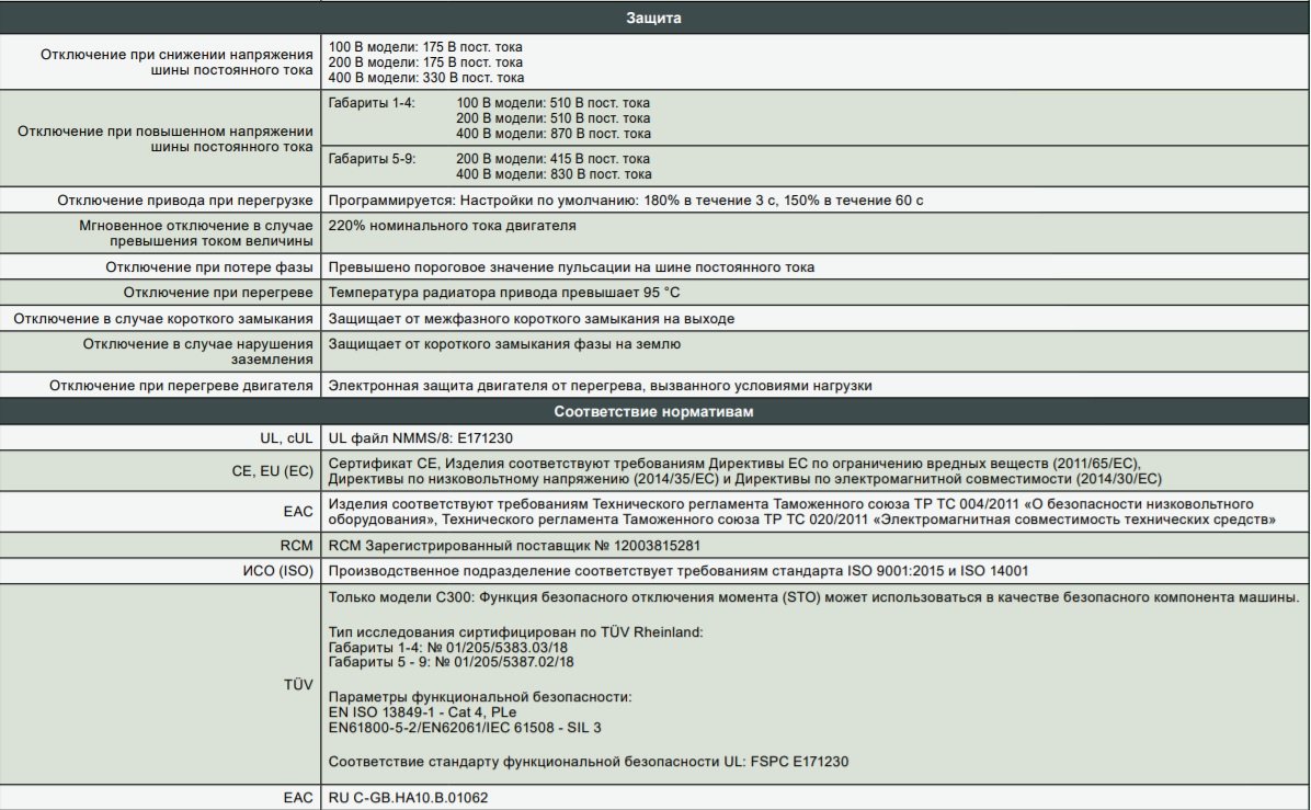
| Основные характеристики | |
| Серия | C200 |
| Тип | Общепромышленные механизмы |
| Выходной ток, А | 2.3 |
| Максимальная мощность рассеивания, кВт | . |
| Мощность двигателя, кВт | 0.75 |
| Напряжение питания, В | 3Ф/380В |
| Размер дисплея, дюйма | . |
| Тип модуля | . |
| Выходное напряжение, В | 3Ф/380 В |
| Частота питания, Герц | 45 -66 Гц |
| Выходная частота, Герц | 0 … 550 Гц |
| Перегрузочная способность | 150 % |
| Встроенный потенциометр | Нет |
| Тип двигателя | Асинхронный |
| Панель программирования в комплекте с ПЧ | Несъемная |
| Влажность | до 95% без конденсации |
| Температура окружающего воздуха для работы | -20 … 40 ° C |
| ЭМС-фильтр | Опция |
| Тормозной модуль | Встроенный |
| Встроенный вентилятор | Есть |
| Протокол порта связи | ModBus |
| Степень защиты IP | IP20 без заглушки в верхней части |
| Карты расширения | EthernetIP, ProfibusDP, DeviceNet, CANopen daisychain, ProfiNet, EtherCAT |
| Вес, кг | 1,3 |
| Габаритные размеры. (ВхШхГ), мм | 205х78х150 мм |
| Страна (Бренд/Производство) | Великобритания/Великобритания |
| Число и тип входов/выходов | |
| Общее количество входов/выходов | . |
| Число/Тип аналоговых входов | 2 (0-5(10)V или 0(4)-20mA) |
| Число/Тип дискретных выходов | 1 ( 24 В DC, 8 мA/12 В DC) |
| Число/Тип аналоговых выходов | 1 (0-10V или 0(4)-20mA) |
| Число/Тип дискретных входов | 4 (NPN переход, 24 В DC, 8 мA/12 В DC, 4 мA) |
| Число/Тип релейных выходов | 1 (250 В AC, 3 A / 30 В DC, 3 A) |
| Закон управления асинхронным двигателем | |
| Векторное управление потоком без датчика соотношение (SVC) | Есть |
| Векторное управление с обратной связью | Нет |
| Скалярное (V/f) соотношение напряжение/частота | Есть |
| Защиты | |
| От замыкания на землю | Есть |
| От короткого замыкания | Есть |
| От нарушения последовательности чередования фаз | Есть |
| Перегрев двигателя | Есть |
| Пониженное и повышенное напряжение питающей сети | Есть |
| Потеря фаз | Есть |

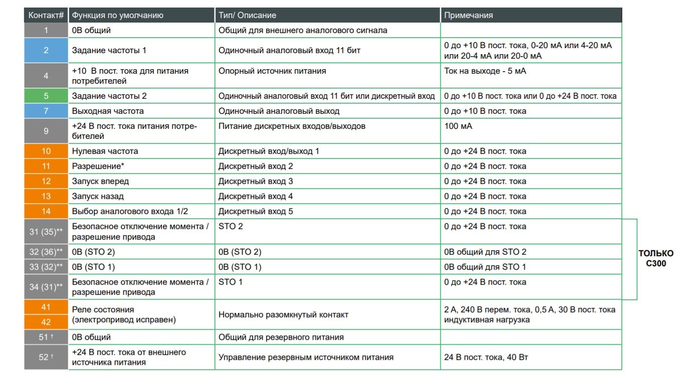
Насосы,вентиляторы и компрессоры
◼Улучшенная энергоэффективность в периоды низкой загрузки
◼Встроенные ПЛК и ПИД-регулятор облегчают управление и делают его болееэффективным, не требуя применения внешнего контроллера
◼Пропускаемые частоты позволяют пользователям легко избежать резонансных явлений в оборудовании, сокращая уровень вибрации
◼Резервное питание помогает поддерживать привод в рабочем состоянии даже в случае отключения электроснабжения.
Конвейеры
◼Точное дистанционное управление скоростью при подключении по промышленной сети
◼Профиль ускорения/ замедления S-рампы обеспечивает плавные переходы скорости,сводя к минимуму рывки машины
◼Перегрузочная способность до 180%, что добавляет стабильность
◼Предотвращает преждевременный износ оборудования
Лифты,подъемники и лебедки
◼Настраиваемый алгоритм наложения механического тормоза с функцией контроля крутящего момента – нет необходимости во внешнем контроллере
◼Функции встроенного ПЛК может управлять локальным входами/ выходами, сокращая потребность во внешнем контроллере
Управление доступом
◼Плавное движение с улучшенным управлением в разомкнутом контуре
◼Небольшие физические размеры позволяют легко монтировать привод в небольших шкафах управления
◼Высокая надежность в суровых условиях работы, обеспечивает длительный срок службы
Обработка(миксеры, дробилки, мешалки, центрифуги, экструдеры)
◼Простота интеграции с внешним ПЛК или другими системами управления, благодаря мощным сетевым возможностям
◼Покрытие плат для улучшения защиты от условий окружающей среды
◼Перегрузочная способность до 180%
◼Стабильное управление двигателем

Цена по запросу.
Цена по запросу.

Цена по запросу.
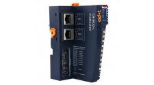
Цена по запросу.
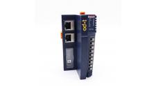
Цена по запросу.
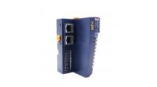
Цена по запросу.
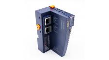
Цена по запросу.
Цена по запросу.

Цена по запросу.
Цена по запросу.
CONTROL TECHNIQUES

Розничная цена: 83076
Цена по запросу.
Цена по запросу.
Цена по запросу.
Цена по запросу.
Цена по запросу.
Цена по запросу.
Цена по запросу.
Цена по запросу.
Цена по запросу.
Цена по запросу.
CONTROL TECHNIQUES
Розничная цена: 83076
Цена по запросу.
Цена по запросу.
Цена по запросу.
Цена по запросу.
Цена по запросу.
Цена по запросу.
Цена по запросу.
Цена по запросу.
Цена по запросу.
Цена по запросу.
CONTROL TECHNIQUES
Розничная цена: 83076
Цена по запросу.
Цена по запросу.
Цена по запросу.
Цена по запросу.
Цена по запросу.
Цена по запросу.
Цена по запросу.
Цена по запросу.
Цена по запросу.
Цена по запросу.
CONTROL TECHNIQUES
Розничная цена: 86172
Цена по запросу.
Цена по запросу.
Цена по запросу.
Цена по запросу.
Цена по запросу.
Цена по запросу.
Цена по запросу.
Цена по запросу.
Цена по запросу.
Цена по запросу.
CONTROL TECHNIQUES
Розничная цена: 86172
Цена по запросу.
Цена по запросу.
Цена по запросу.
Цена по запросу.
Цена по запросу.
Цена по запросу.
Цена по запросу.
Цена по запросу.
Цена по запросу.
Цена по запросу.
CONTROL TECHNIQUES
Розничная цена: 86172
Цена по запросу.
Цена по запросу.
Цена по запросу.
Цена по запросу.
Цена по запросу.
Цена по запросу.
Цена по запросу.
Цена по запросу.
Цена по запросу.
Цена по запросу.
CONTROL TECHNIQUES
Розничная цена: 88752
Цена по запросу.
Цена по запросу.
Цена по запросу.
Цена по запросу.
Цена по запросу.
Цена по запросу.
Цена по запросу.
Цена по запросу.
Цена по запросу.
Цена по запросу.
CONTROL TECHNIQUES
Розничная цена: 88752
Цена по запросу.
Цена по запросу.
Цена по запросу.
Цена по запросу.
Цена по запросу.
Цена по запросу.
Цена по запросу.
Цена по запросу.
Цена по запросу.
Цена по запросу.
CONTROL TECHNIQUES
Розничная цена: 88752
Цена по запросу.
Цена по запросу.
Цена по запросу.
Цена по запросу.
Цена по запросу.
Цена по запросу.
Цена по запросу.
Цена по запросу.
Цена по запросу.
Цена по запросу.
CONTROL TECHNIQUES
Розничная цена: 92880
Цена по запросу.
Цена по запросу.
Цена по запросу.
Цена по запросу.
Цена по запросу.
Цена по запросу.
Цена по запросу.
Цена по запросу.
Цена по запросу.
Цена по запросу.
CONTROL TECHNIQUES
Розничная цена: 92880
Цена по запросу.
Цена по запросу.
Цена по запросу.
Цена по запросу.
Цена по запросу.
Цена по запросу.
Цена по запросу.
Цена по запросу.
Цена по запросу.
Цена по запросу.
CONTROL TECHNIQUES
Розничная цена: 92880
Цена по запросу.
Цена по запросу.
Цена по запросу.
Цена по запросу.
Цена по запросу.
Цена по запросу.
Цена по запросу.
Цена по запросу.
Цена по запросу.
Цена по запросу.
CONTROL TECHNIQUES
Розничная цена: 102684
Цена по запросу.
Цена по запросу.
Цена по запросу.
Цена по запросу.
Цена по запросу.
Цена по запросу.
Цена по запросу.
Цена по запросу.
Цена по запросу.
Цена по запросу.
CONTROL TECHNIQUES
Розничная цена: 102684
Цена по запросу.
Цена по запросу.
Цена по запросу.
Цена по запросу.
Цена по запросу.
Цена по запросу.
Цена по запросу.
Цена по запросу.
Цена по запросу.
Цена по запросу.
CONTROL TECHNIQUES
Розничная цена: 102684
Цена по запросу.
Цена по запросу.
Цена по запросу.
Цена по запросу.
Цена по запросу.
Цена по запросу.
Цена по запросу.
Цена по запросу.
Цена по запросу.
Цена по запросу.
CONTROL TECHNIQUES

Розничная цена: 121776
Цена по запросу.
Цена по запросу.
Цена по запросу.
Цена по запросу.
Цена по запросу.
Цена по запросу.
Цена по запросу.
Цена по запросу.
Цена по запросу.
Цена по запросу.
CONTROL TECHNIQUES
Розничная цена: 121776
Цена по запросу.
Цена по запросу.
Цена по запросу.
Цена по запросу.
Цена по запросу.
Цена по запросу.
Цена по запросу.
Цена по запросу.
Цена по запросу.
Цена по запросу.
CONTROL TECHNIQUES
Розничная цена: 121776
Цена по запросу.
Цена по запросу.
Цена по запросу.
Цена по запросу.
Цена по запросу.
Цена по запросу.
Цена по запросу.
Цена по запросу.
Цена по запросу.
Цена по запросу.
CONTROL TECHNIQUES
Розничная цена: 133644
Цена по запросу.
Цена по запросу.
Цена по запросу.
Цена по запросу.
Цена по запросу.
Цена по запросу.
Цена по запросу.
Цена по запросу.
Цена по запросу.
Цена по запросу.
CONTROL TECHNIQUES
Розничная цена: 133644