-
Contents
-
Table of Contents
-
Bookmarks
Quick Links
User Manual
Color video door phone CDV-35U
Thank you for purchasing COMMAX products.
Please carefully read this User’s Guide (in particular, precautions for safety) before using a product and follow
instructions to use a product exactly.
The company is not responsible for any safety accidents caused by abnormal operation of the product.
www.safemag.ru
www.safemag.ru
Related Manuals for Commax CDV-35U
Summary of Contents for Commax CDV-35U
-
Page 1: User Manual
User Manual Color video door phone CDV-35U Thank you for purchasing COMMAX products. Please carefully read this User’s Guide (in particular, precautions for safety) before using a product and follow instructions to use a product exactly. The company is not responsible for any safety accidents caused by abnormal operation of the product.
-
Page 2: Table Of Contents
4. How to use this product ………………5 5. Initialization (RESET) ………………..8 6. How to install………………….9 7. Wiring ……………………10 8. Parts list ………………….12 9. Miscellaneous …………………12 10. Specification………………….13 1. Greetings Thank you for choosing COMMAX. Please read this manual carefully before you use the product. www.safemag.ru…
-
Page 3: Warnings And Caution
www.safemag.ru 2. Warnings and caution Please follow the things described below in order to prevent any danger or property damage. Prohibition. Warning It may cause a serious damage or No disassembly injury if violated. No touch Must follow strictly. Shows plugging out the power cord Caution It may cause a minor damage or without an exception…
-
Page 4
www.safemag.ru Warning Please don t disassemble, If an abnormal sound, burning Please don t insert any Please use only the designated repair or rebuild this product smell or smoke is coming out metallic or burnable materials batteries for the products of arbitrarily (please contact the of the product, please plug out into the ventilation hole. -
Page 5: Parts And Function
www.safemag.ru 3. Parts and function Name Name POWER SWITCH DOOR RELEASE BUTTON/UP BUTTON POWER AND DISPLAY LED MENU BUTTON MICROPHONE TALK BUTTON LCD MONITOR SPEAKER MONITOR BUTTON CONNECTION TERMINAL INTERPHONE BUTTON / DOWN BUTTON 1. POWER SWITCH : ON/OFF switch 2.
-
Page 6: How To Use This Product
www.safemag.ru 11. TERMINAL FOR EXTERIOR : terminal for product upgrade, entrance camera and interphone connection. 4. How to use this product 1. Call from the visitor When the visitor calls from the entrance(door camera), the calling sound rings and the image of the visitor is shown on the screen.
-
Page 7
www.safemag.ru ③ 3-way communication is possible between household, interphone and door camera when visi- tor calls from door camera, while household is talking with interphone. Image from door cam- era is displayed on the screen of household with calling sound and 3-way communication gets available. -
Page 8
www.safemag.ru — Volume of ringing sound and receiver sound consists of 3 steps and you cannot change it any more despite pressing UP/DOWN button with certain sound (beep beep sound)in Max/Min status. 5. Image setting_ BRIGHT / CONT / COLOR adjustment (available when the screen is on) … -
Page 9: Initialization (Reset)
www.safemag.ru — You are in COLOR adjustment mode. — Press the UP(Door release button) / DOWN(Interphone button) button in front of the product in order to adjust the condition of the COLOR. — After completing the set, save the revised setting value by pressing the menu button. (LED lamp will be changed from red to blue.) Reference : if you press the menu button, menu mode will work as follws.
-
Page 10: How To Install
www.safemag.ru 6. How to install 1. Installation Method of Video Door Phone Note Avoid the range of direct sunlight Recommended height is pertinent from 1450 ~ 1500mm Avoid the installation near magnetic activity, humid temperatures and gas 2. Installation Method of Camera Note Do not install the camera where it is exposed to Direct sunlight Keep cleaning up its lens to capture good views.
-
Page 11: Wiring
www.safemag.ru 7. Wiring Camera connector The wiring of this equipment is as follows, 1. Red : Voice 2. Blue : GND 3.Yellow : DC 12V 4.White : Video When using UTP CABLE[CAT.5] for better image quality, connect the rest 4 lines to GND after con- necting 4 lines with monitor and camera.
-
Page 12
www.safemag.ru DOOR Camera wiring When using UTP CABLE[CAT.5] for better image quality, connect the rest 4 lines to GND after connecting 4 lines with monitor and camera. DOOR Camera wiring When using UTP CABLE[CAT.5] for better image quality, connect the rest 4 lines to GND after connecting 4 lines with monitor and interphone. -
Page 13: Parts List
8. Parts list Manual Body of CDV-35U Bracket for wall mount 4P Connector(2EA) M3 x 6(1EA) T4 X 18(4EA) Screw for body Screw for wall mount ① Main body(CDV-35U) ② Bracket for wall surface mounting ③ User Manual ④ Screw for wall bracket (SCREW GH1T 4X18 ZnY) — 4EA ⑤…
-
Page 14
513-11, Sangdaewon-dong, Jungwon-gu, Seongnam-si, Gyeonggi-do, Korea Int’l Business Dept. Tel. : +82-31-7393-540~550 Fax. : +82-31-745-2133 513-11, Sangdaewon-dong, Jungwon-gu, Seongnam-si, Gyeonggi-do, Korea Web site : www.commax.com Int’l Business Dept. Tel. : +82-31-7393-540~550 Fax. : +82-31-745-2133 PM0735U00010 Printed In Korea / 2012.05.104 Web site : www.commax.com… -
Page 15: Specification
10. Specification CDV-35U Model Spec Rating Voltage 100-240V~, 50/60Hz (FREE VOLTAGE) Consumption Operation: 10W(MAX) Transmission Entrance 4wires polarity, interphone 4wires polarity Screen size 3.5″ TFT-DIGITAL LCD Call mode HANDS FREE Call mode (Voice switch circuit) Entrance : electronic chime,…
User Manual
Color video door phone CDV-35U
513-11, Sangdaewon-dong, Jungwon-gu, Seongnam-si, Gyeonggi-do, Korea
Int’l Business Dept. Tel. : +82-31-7393-540~550 Fax. : +82-31-745-2133
Web site : www.commax.com
•
Thank you for purchasing COMMAX products.
•
Please carefully read this User’s Guide (in particular, precautions for safety) before using a product and follow instructions to use a product exactly.
•
The company is not responsible for any safety accidents caused by abnormal operation of the product.
코맥스 제품을 구입해 주셔서 대단히 감사합니다.
사용하시기 전에 본 설명서(특히 안전을 위한 주의사항)를 잘 읽어 보시고, 정확하게 사용하여 주시기 바랍니다.
본 제품이 정상적인 동작상태가 아닌 상황에서 발생한 방범 및 방재사고에 대해서는 당사가 책임지지 않습니다.
Table of contents
1. Greetings ………………………………………………………………………………………………..1
2. Warnings and caution ……………………………………………………………………………….2
3. Parts and function …………………………………………………………………………………….4
4. How to use this product …………………………………………………………………………….5
5. Initialization (RESET)………………………………………………………………………………..8
6. How to install……………………………………………………………………………………………9
7. Wiring……………………………………………………………………………………………………10
8. Parts list ……………………………………………………………………………………………….12
9. Miscellaneous ………………………………………………………………………………………..12
10. Specification…………………………………………………………………………………………13
1. Greetings
●
Thank you for choosing COMMAX.
●
Please read this manual carefully before you use the product.
1
2. Warnings and caution
Please follow the things described below in order to prevent any danger or property damage.
Warning
It may cause a serious damage or injury if violated.
Caution
It may cause a minor damage or injury if violated.
Prohibition.
No disassembly
No touch
Must follow strictly.
Shows plugging out the power cord without an exception
Shows the warning and caution for an electric shock.
Shows the warning and caution for a fire.
Warning
Please don
䯱 t use several products at the same time on one power socket.
䯦
It may cause a fire due to an abnormal overheating.
Please don
䯱 cable excessively or it may cause an electric shock.
䯦 fire when using a damaged power cable.
Please don
䯱 cable with a wet hand.
䯦
It may cause an electric shock.
Please plug out the power cable from the socket when not using it for a long period of time.
䯦
It may shorten the product lifespan or cause a fire.
Please don
䯱 t install the product in the place where there is much oil, smoke or humidity.
䯦
It may cause an electric shock or fire.
Please don
䯱 t install the product with the lightening and thunder.
䯦
It may cause an electric shock or fire.
Please don
䯱 this product with other products with different rated voltage
䯦
It may cause a disorder or fire.
When installing the product that generates heat, please install the product away from the wall (10cm) for the ventilation.
䯦
It may cause a fire due to the increased internal temperature.
2
Warning
Please don
䯱 repair or rebuild this product arbitrarily (please contact the service center if a repair is needed.
䯦
It may cause an electric shock or fire.
If an abnormal sound, burning smell or smoke is coming out of the product, please plug out the power cable and contact a service center.
䯦
It may cause an electric shock or fire.
Please don
䯱 t insert any metallic or burnable materials into the ventilation hole.
䯦
It may cause an electric shock or fire.
Please use only the designated batteries for the products of using DC power.
䯦
It may cause an electric shock or fire.
Caution
Please plug the power cable firmly into the inner end
䯦
It may cause a fire.
Please hold the plug tightly when unplugging the power cable (a part of the copper wire may be disconnected if the grabbing is only made on the cord when pulling out the cable).
䯦
It may cause an electric shock or fire
When connecting the power cables after cutting the cable, please install the product with power off
䯦 It may cause an electric shock or fire
When installing the product, please fix it firmly while using the wall-mounting unit and screws.
䯦 It may cause an injury from the falling object.
Please be careful when using an AC circuit breaker since there is a possibility of an electric shock.
Please check the use voltage and current for the DC-only products and use the appropriate rectifier.
䯦
It may cause a fire.
Please avoid direct rays of the sun or heating devices at a time of installation.
䯦
It may cause a fire.
Please don
䯱 t install the product on an unstable place or small support board.
䯦
It may cause an injury if it falls down while in use.
When cleaning the product, please rub it with a soft and dry cloth after plugging out the power cable. (Please don
䯱 use any chemical products such as wax, benzene, alcohol or cleanser.)
Please don
䯱 on the ground and don
䯱 a shock .
䯦
It may cause a failure.
Please use the designated connection cable within the maximum calling distance designated for the product
䯦
It may reduce the product performance.
3
3. Parts and function
嗻
NO.
Name
NO.
Name
1 POWER SWITCH
2 POWER AND DISPLAY LED
7 DOOR RELEASE BUTTON/UP BUTTON
8 MENU BUTTON
3 MICROPHONE
4 LCD MONITOR
5 MONITOR BUTTON
10 SPEAKER
11 CONNECTION TERMINAL
6 INTERPHONE BUTTON / DOWN BUTTON
1. POWER SWITCH : ON/OFF switch
2. POWER AND DISPLAY LED
: blue in power on mode and light-out in power off mode.
3. MICROPHONE
4. LCD MONITOR
5. MONITOR BUTTON(ENTRANCE) : to check the situation of entrance.
6. INTERPHONE button: to call the interphone.
(UP BUTTON : to level up in the menu)
7. DOOR RELEASE BUTTON: to release the door for visitor.
(DOWN BUTTON : to level down in the menu)
8. MENU BUTTON : to enter or exit the menu for screen control, call sound and receiver volume
9. TALK BUTTON : to answer for visitor.
10. SPEAKER
4
11. TERMINAL FOR EXTERIOR : terminal for product upgrade, entrance camera and interphone connection.
4. How to use this product
1. Call from the visitor
①
When the visitor calls from the entrance(door camera), the calling sound rings and the image of the visitor is shown on the screen.
②
If you press the talk button, you can talk with door camera. By pressing the door release button, door will be released. (Door release works only while talking.)
(Please note that this function is possible only when the door camera is interlocked with door release function.)
③
3-way communication is possible when another user picks up the handset of extended interphone, when you are talking with door camera on video door phone.
(Entrance-Household -Interphone simultaneous communication mode)
④
If you press the talk button, again talking is finished and video door phone turns to stand-by mode. (You can install additional camera. In case of receiving call from camera 1, blue LED blinks. In case of receiving call from camera 2, purple LED blinks.)
2. Call with additional interphone
2-1. Call between door camera and interphone
①
When the visitor calls from the door camera, calling sound rings on interphone and video door phone.
②
By picking up the handset of interphone, you can talk with door camera. By pressing the door release button, door will be released.
2-2. Talk between interphone and video door phone(household).
(1) In case of receiving the call of household phone from interphone
①
In order to call the household from interphone, pick up the interphone handset and press call button. Then, video phone will be ringing.
②
You can talk with interphone by pressing the call button of household or interphone button.
5
③
3-way communication is possible between household, interphone and door camera when visitor calls from door camera, while household is talking with interphone. Image from door camera is displayed on the screen of household with calling sound and 3-way communication gets available.
④
If you press the interphone button or talk button after ending the call
(2) In case of calling interphone from household
①
Press Talk Button and Interphone Button in order to call the interphone.
(Interphone is called only while the interphone button on household is being pressed.)
②
When you receive the call from interphone, enjoy the call.
3. Monitoring : function to see the image of visitor in the entrance.
(On stand-by mode) Operation
— By pressing the Monitor button repeatedly, the monitor will work as following in order.
Camera 1
( Camera 2)
OFF
Camera 1
……
(On talking mode) Operation
— By pressing the Monitor button repeatedly, the monitor will work as following in order.
Camera 1
Camera 2
Camera 1
Camera 2
……
[Caution : If you use only 1 camera, press monitor button while talking, the call with entrance will be ended.]
4. Volume control (ringing sound/receiver sound)
(1) Call volume control : adjustable on stand-by status.
①
Press the menu button one time on stand-by status.
②
Red LED will be turned on(lighting) : call volume control mode.
③
Adjust it with UP(door release) / DOWN(interphone) button.
(Ringing sound of new size will ring one time when controlling by pressing control button in order to check the volume)
(2) Receiver volume control : adjustable while talking
①
Press the menu button one time while talking.
②
Red LED will be turned on(lighting) : receiver volume control mode
③
Adjust it with UP(door release) / DOWN(interphone) button
6
— Volume of ringing sound and receiver sound consists of 3 steps and you cannot change it any more despite pressing UP/DOWN button with certain sound (beep beep sound)in
Max/Min status.
5. Image setting_ BRIGHT / CONT / COLOR adjustment
(available when the screen is on)
The image setting mode will be sequentially operated when user presses the menu button as follows.
— Calling : BRIGHT
CONTRAST
COLOR
RETURN
BRIGHT
…
— Talking : Receiver sound adjustment
BRIGHT
CONTRAST
COLOR
RETURN
Receiver sound adjustment
BRIGHT
…
5-1. BRIGHT brightness adjustment
— Press the menu button once when the image is on.
(LED lamp will be changed from blue to red.)
Red LED blinks fast. [
◦◦◦◦
]
— You are in brightness adjustment mode.
— Press the UP(Door release) / DOWN(Interphone) button in front of the product in order to adjust the brightness.
— After completing the set, save the revised setting value by pressing the menu button.
(LED lamp will be changed from red to blue.)
5-2. CONTRAST contrast adjustment
— Press the menu button twice when the image is on. (While talking: 3 times)
(LED lamp will be changed from blue to red.)
Red LED blinks slowly. [
◦◦◦◦◦◦◦◦
]
— You are in CONTRAST adjustment mode.
— Press the UP(Door release) / DOWN(Interphone) button in front of the product in order to adjust the CONTRAST.
— After completing the set, save the revised setting value by pressing the menu button.
(LED lamp will be changed from red to blue.)
5-3. COLOR color adjustment
— Press the menu button three times in the state of the image on. (while talking 4 times)
(LED lamp will be changed from blue to red.)
Red LED blinks very slowly. [
◦◦◦◦◦◦◦◦◦◦◦◦
]
7
— You are in COLOR adjustment mode.
— Press the UP(Door release button) / DOWN(Interphone button) button in front of the product in order to adjust the condition of the COLOR.
— After completing the set, save the revised setting value by pressing the menu button.
(LED lamp will be changed from red to blue.)
Reference : if you press the menu button, menu mode will work as follws.
Stand-by : Ringing sound adjustment
return
Ringing sound adjustment
…
Calling : BRIGHT
CONTRAST
COLOR
return
BRIGHT
…
Talking : Receiver sound adjustment
BRIGHT
CONTRAST
COLOR
return
Receiver sound adjustment
…
Menu according to LED condition.
1. Ringing sound adjustment(stand-by) : red LED lighting (on)
2. Receiver sound adjustment(talking) : red LED lighting (on)
3. Image brightness adjustment(image–monitoring/call) : red LED flickering (blinking at a fast pace)
4. Image contrast adjustment(image-monitoring/call) : red LED flickering (blinking at a normal pace)
5. Image color adjustment(image-monitoring/call) : red LED flickering (blinking at a slow pace)
[Caution : menu will be over if there’s no key input for 5 seconds with toot toot sound in the state of menu.]
5. Initialization (RESET)
Press the interphone button and door release button at the same time for about 3 seconds.
Then, image setting value and sound volume will be initialized.
8
6. How to install
1. Installation Method of Video Door Phone
SCREW M3 (1EA)
SCREW T4 (4EA)
Note
①
Avoid the range of direct sunlight
②
Recommended height is pertinent from 1450 ~ 1500mm
③
Avoid the installation near magnetic activity, humid temperatures and gas
2. Installation Method of Camera
SCREW PHM 3X8
SCREW CAP
DRC-41QC
Note
①
Do not install the camera where it is exposed to Direct sunlight
②
Keep cleaning up its lens to capture good views.
9
7. Wiring
Camera connector
p
The wiring of this equipment is as follows,
1. Red : Voice 2. Blue : GND 3.Yellow : DC 12V 4.White : Video
When using UTP CABLE[CAT.5] for better image quality, connect the rest 4 lines to GND after connecting 4 lines with monitor and camera.
Wiring precautions
•
Each device should be connected by separated cables.
To use CAMERA 1, CAMERA 2 and interphone using UTP CABLE[CAT.5], 3 lines of UTP cable are required.
10
DOOR Camera wiring
•
When using UTP CABLE[CAT.5] for better image quality, connect the rest 4 lines to
GND after connecting 4 lines with monitor and camera.
DOOR Camera wiring
•
When using UTP CABLE[CAT.5] for better image quality, connect the rest 4 lines to
GND after connecting 4 lines with monitor and interphone.
11
12
8. Parts list
①
Body of CDV-35U
②
Bracket for wall mount
③
Manual
④
T4 X 18(4EA)
Screw for wall mount
⑤
M3 x 6(1EA)
Screw for body
⑥
4P Connector(2EA)
①
Main body(CDV-35U)
②
Bracket for wall surface mounting
③
User Manual
④
Screw for wall bracket (SCREW GH1T 4X18 ZnY) — 4EA
⑤
Screw for body (SCREW PHM 3X6 ZnY) — 1EA
⑥
Camera connector (CONN. 4PX300) — 2EA
9. Miscellaneous
● Please carefully read this User Manual before calling service
After checking the entire list, please contact customer service center.
We will do our best to make you satisfy with our services.
513-11, Sangdaewon-dong, Jungwon-gu, Seongnam-si, Gyeonggi-do, Korea
Int’l Business Dept. Tel. : +82-31-7393-540~550 Fax. : +82-31-745-2133
Web site : www.commax.com
Web site : www.commax.com
Printed In Korea / 2012.05.104
•
Thank you for purchasing COMMAX products.
•
•
Please carefully read this User’s Guide (in particular, precautions for safety) before using a product and follow
•
Please carefully read this User’s Guide (in particular, precautions for safety) before using a product and follow
• instructions to use a product exactly.
The company is not responsible for any safety accidents caused by abnormal operation of the product.
•
The company is not responsible for any safety accidents caused by abnormal operation of the product.
10. Specification
Spec
Model
Rating Voltage
CDV-35U
100-240V~, 50/60Hz (FREE VOLTAGE)
Consumption
Transmission
Screen size
Call mode
Entrance 4wires polarity, interphone 4wires polarity
3.5″ TFT-DIGITAL LCD
HANDS FREE Call mode (Voice switch circuit)
Entrance : electronic chime,
Ringing sound
Interphone : electronic buzzer
60 ±10sec (During conversation)
Screen Display
30 ±10sec (During monitoring)
Distance
(Cable thickness)
28m(
Ø
0.5) / 50m(
Ø
0.65) / 70m(
Ø
0.8)
Working temperature 0 ~ +40°C (32°F ~ 104°F)
Dimension 180.0(W)X180.0(H)X28.5(D)
13
Код 159766
Подключение вызывных панелей
2
Количество камер
2
Подключение дополнительных мониторов
1
Система изображения
PAL/NTSC
Подключение аудиотрубки
нет
Производитель
Перейти к описанию
1019 просмотров
- Описание
- Технические характеристики
- Параметры9
- Отзывы
- Документация
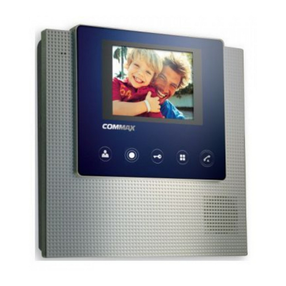
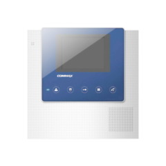
Commax CDV-35U синий — цветной видеодомофон hands-free на 2 камеры с сенсорными кнопками.Тип экрана: TFT матрица со светодиодной подсветкой (LED-подсветкой), обеспечивающей более четкое и насыщенное изображение, диагональ 3,5 дюйма (8,9 см). Монитор позволяет увидеть на экране монитора посетителя, позвонившего в вызывную панель, поговорить с ним, открыть электромеханический замок нажатием кнопки на мониторе.
Переключение на вторую видеокамеру осуществляется повторным нажатием на кнопку просмотра изображения. Длительность работы дисплея во включенном состоянии: после ручного включения кнопкой на мониторе: 30 сек. после поступления сигнала от вызывной панели: 60 сек. Возможно подключение дополнительной трубки DP-4VHP. Возможно параллельное подключение мониторов к вызывным панелям. Максимальная конфигурация для параллельного включения: 2 монитора, 2 вызывных панели, 2 дополнительные трубки.
Возможно подключение к подъездному домофону через блоки сопряжения. Видеодомофон работает с цветными вызывными панелями в стандартах PAL или NTSC (автоопределение). При монтаже необходимо соблюдать дистанцию не менее 1,5 м между монитором и вызывной панелью. При несоблюдении указанной дистанции, во время разговора возможно появление фона и свиста.
- Единица измерения: 1 шт
- Габариты (мм): 180x180x27
- Масса (кг): 1.50
Технические характеристики Commax CDV-35U синий
- Тип экрана Fine View Color LCD
- Система цветности PAL/NTSC
- Размер экрана по диагонали 3,5”
- Подсветка LED
- Регулировка яркости, контрастности да
- Система Hands-free (свободные руки) да
- Регулировка громкости да
- Количество мелодий вызова 1
- Тип мелодии тональный
- Встроенная память нет
- Видеовыходов 2 видео 2 аудио
- Тип управления Сенсорные кнопки
- Соединение с вызывной панелью 4-х проводное
- Maксимальная длина провода домофон-видеопанель 50 метров
- Интерфон есть, DP-4VН
- Корпус пластик
- Цвет синий
- Диапазон рабочих температур 0… +50С
- Напряжение сети 100-240В 50/60Гц.
- Потребляемая мощность 1Вт-6,25Вт
- Вес 1,9 кг.
- Размер (В*Ш*Г) 180х180х27
- Способ установки накладной
- Язык меню русский, английский.
Параметры9
| Диагональ экрана | 4.3 |
| Подключение вызывных панелей | 2 |
| Количество камер | 2 |
| Подключение дополнительных мониторов | 1 |
| Система изображения | PAL/NTSC |
| Общий вызов | Нет |
| Подключение аудиотрубки | Нет |
| Цвет внутренних блоков | Синий |
| Место установки | внутренние |
Отзывы на товар Commax CDV-35U синий
Документация
*Производитель оставляет за собой право изменять характеристики товара, его внешний вид и комплектность без предварительного уведомления продавца. Не является публичной офертой согласно Статьи 437 п.2 ГК РФ.
Заметили ошибку? Выделите ее мышкой и нажмите «Ctrl+Enter»
User Manual
Color video door phone CDV-35U
513-11, Sangdaewon-dong, Jungwon-gu, Seongnam-si, Gyeonggi-do, Korea
Int’l Business Dept. Tel. : +82-31-7393-540~550 Fax. : +82-31-745-2133
Web site : www.commax.com
•
Thank you for purchasing COMMAX products.
•
Please carefully read this User’s Guide (in particular, precautions for safety) before using a product and follow instructions to use a product exactly.
•
The company is not responsible for any safety accidents caused by abnormal operation of the product.
코맥스 제품을 구입해 주셔서 대단히 감사합니다.
사용하시기 전에 본 설명서(특히 안전을 위한 주의사항)를 잘 읽어 보시고, 정확하게 사용하여 주시기 바랍니다.
본 제품이 정상적인 동작상태가 아닌 상황에서 발생한 방범 및 방재사고에 대해서는 당사가 책임지지 않습니다.
Table of contents
1. Greetings ………………………………………………………………………………………………..1
2. Warnings and caution ……………………………………………………………………………….2
3. Parts and function …………………………………………………………………………………….4
4. How to use this product …………………………………………………………………………….5
5. Initialization (RESET)………………………………………………………………………………..8
6. How to install……………………………………………………………………………………………9
7. Wiring……………………………………………………………………………………………………10
8. Parts list ……………………………………………………………………………………………….12
9. Miscellaneous ………………………………………………………………………………………..12
10. Specification…………………………………………………………………………………………13
1. Greetings
●
Thank you for choosing COMMAX.
●
Please read this manual carefully before you use the product.
1
2. Warnings and caution
Please follow the things described below in order to prevent any danger or property damage.
Warning
It may cause a serious damage or injury if violated.
Caution
It may cause a minor damage or injury if violated.
Prohibition.
No disassembly
No touch
Must follow strictly.
Shows plugging out the power cord without an exception
Shows the warning and caution for an electric shock.
Shows the warning and caution for a fire.
Warning
Please don
䯱 t use several products at the same time on one power socket.
䯦
It may cause a fire due to an abnormal overheating.
Please don
䯱 cable excessively or it may cause an electric shock.
䯦 fire when using a damaged power cable.
Please don
䯱 cable with a wet hand.
䯦
It may cause an electric shock.
Please plug out the power cable from the socket when not using it for a long period of time.
䯦
It may shorten the product lifespan or cause a fire.
Please don
䯱 t install the product in the place where there is much oil, smoke or humidity.
䯦
It may cause an electric shock or fire.
Please don
䯱 t install the product with the lightening and thunder.
䯦
It may cause an electric shock or fire.
Please don
䯱 this product with other products with different rated voltage
䯦
It may cause a disorder or fire.
When installing the product that generates heat, please install the product away from the wall (10cm) for the ventilation.
䯦
It may cause a fire due to the increased internal temperature.
2
Warning
Please don
䯱 repair or rebuild this product arbitrarily (please contact the service center if a repair is needed.
䯦
It may cause an electric shock or fire.
If an abnormal sound, burning smell or smoke is coming out of the product, please plug out the power cable and contact a service center.
䯦
It may cause an electric shock or fire.
Please don
䯱 t insert any metallic or burnable materials into the ventilation hole.
䯦
It may cause an electric shock or fire.
Please use only the designated batteries for the products of using DC power.
䯦
It may cause an electric shock or fire.
Caution
Please plug the power cable firmly into the inner end
䯦
It may cause a fire.
Please hold the plug tightly when unplugging the power cable (a part of the copper wire may be disconnected if the grabbing is only made on the cord when pulling out the cable).
䯦
It may cause an electric shock or fire
When connecting the power cables after cutting the cable, please install the product with power off
䯦 It may cause an electric shock or fire
When installing the product, please fix it firmly while using the wall-mounting unit and screws.
䯦 It may cause an injury from the falling object.
Please be careful when using an AC circuit breaker since there is a possibility of an electric shock.
Please check the use voltage and current for the DC-only products and use the appropriate rectifier.
䯦
It may cause a fire.
Please avoid direct rays of the sun or heating devices at a time of installation.
䯦
It may cause a fire.
Please don
䯱 t install the product on an unstable place or small support board.
䯦
It may cause an injury if it falls down while in use.
When cleaning the product, please rub it with a soft and dry cloth after plugging out the power cable. (Please don
䯱 use any chemical products such as wax, benzene, alcohol or cleanser.)
Please don
䯱 on the ground and don
䯱 a shock .
䯦
It may cause a failure.
Please use the designated connection cable within the maximum calling distance designated for the product
䯦
It may reduce the product performance.
3
3. Parts and function
嗻
NO.
Name
NO.
Name
1 POWER SWITCH
2 POWER AND DISPLAY LED
7 DOOR RELEASE BUTTON/UP BUTTON
8 MENU BUTTON
3 MICROPHONE
4 LCD MONITOR
5 MONITOR BUTTON
10 SPEAKER
11 CONNECTION TERMINAL
6 INTERPHONE BUTTON / DOWN BUTTON
1. POWER SWITCH : ON/OFF switch
2. POWER AND DISPLAY LED
: blue in power on mode and light-out in power off mode.
3. MICROPHONE
4. LCD MONITOR
5. MONITOR BUTTON(ENTRANCE) : to check the situation of entrance.
6. INTERPHONE button: to call the interphone.
(UP BUTTON : to level up in the menu)
7. DOOR RELEASE BUTTON: to release the door for visitor.
(DOWN BUTTON : to level down in the menu)
8. MENU BUTTON : to enter or exit the menu for screen control, call sound and receiver volume
9. TALK BUTTON : to answer for visitor.
10. SPEAKER
4
11. TERMINAL FOR EXTERIOR : terminal for product upgrade, entrance camera and interphone connection.
4. How to use this product
1. Call from the visitor
①
When the visitor calls from the entrance(door camera), the calling sound rings and the image of the visitor is shown on the screen.
②
If you press the talk button, you can talk with door camera. By pressing the door release button, door will be released. (Door release works only while talking.)
(Please note that this function is possible only when the door camera is interlocked with door release function.)
③
3-way communication is possible when another user picks up the handset of extended interphone, when you are talking with door camera on video door phone.
(Entrance-Household -Interphone simultaneous communication mode)
④
If you press the talk button, again talking is finished and video door phone turns to stand-by mode. (You can install additional camera. In case of receiving call from camera 1, blue LED blinks. In case of receiving call from camera 2, purple LED blinks.)
2. Call with additional interphone
2-1. Call between door camera and interphone
①
When the visitor calls from the door camera, calling sound rings on interphone and video door phone.
②
By picking up the handset of interphone, you can talk with door camera. By pressing the door release button, door will be released.
2-2. Talk between interphone and video door phone(household).
(1) In case of receiving the call of household phone from interphone
①
In order to call the household from interphone, pick up the interphone handset and press call button. Then, video phone will be ringing.
②
You can talk with interphone by pressing the call button of household or interphone button.
5
③
3-way communication is possible between household, interphone and door camera when visitor calls from door camera, while household is talking with interphone. Image from door camera is displayed on the screen of household with calling sound and 3-way communication gets available.
④
If you press the interphone button or talk button after ending the call
(2) In case of calling interphone from household
①
Press Talk Button and Interphone Button in order to call the interphone.
(Interphone is called only while the interphone button on household is being pressed.)
②
When you receive the call from interphone, enjoy the call.
3. Monitoring : function to see the image of visitor in the entrance.
(On stand-by mode) Operation
— By pressing the Monitor button repeatedly, the monitor will work as following in order.
Camera 1
( Camera 2)
OFF
Camera 1
……
(On talking mode) Operation
— By pressing the Monitor button repeatedly, the monitor will work as following in order.
Camera 1
Camera 2
Camera 1
Camera 2
……
[Caution : If you use only 1 camera, press monitor button while talking, the call with entrance will be ended.]
4. Volume control (ringing sound/receiver sound)
(1) Call volume control : adjustable on stand-by status.
①
Press the menu button one time on stand-by status.
②
Red LED will be turned on(lighting) : call volume control mode.
③
Adjust it with UP(door release) / DOWN(interphone) button.
(Ringing sound of new size will ring one time when controlling by pressing control button in order to check the volume)
(2) Receiver volume control : adjustable while talking
①
Press the menu button one time while talking.
②
Red LED will be turned on(lighting) : receiver volume control mode
③
Adjust it with UP(door release) / DOWN(interphone) button
6
— Volume of ringing sound and receiver sound consists of 3 steps and you cannot change it any more despite pressing UP/DOWN button with certain sound (beep beep sound)in
Max/Min status.
5. Image setting_ BRIGHT / CONT / COLOR adjustment
(available when the screen is on)
The image setting mode will be sequentially operated when user presses the menu button as follows.
— Calling : BRIGHT
CONTRAST
COLOR
RETURN
BRIGHT
…
— Talking : Receiver sound adjustment
BRIGHT
CONTRAST
COLOR
RETURN
Receiver sound adjustment
BRIGHT
…
5-1. BRIGHT brightness adjustment
— Press the menu button once when the image is on.
(LED lamp will be changed from blue to red.)
Red LED blinks fast. [
◦◦◦◦
]
— You are in brightness adjustment mode.
— Press the UP(Door release) / DOWN(Interphone) button in front of the product in order to adjust the brightness.
— After completing the set, save the revised setting value by pressing the menu button.
(LED lamp will be changed from red to blue.)
5-2. CONTRAST contrast adjustment
— Press the menu button twice when the image is on. (While talking: 3 times)
(LED lamp will be changed from blue to red.)
Red LED blinks slowly. [
◦◦◦◦◦◦◦◦
]
— You are in CONTRAST adjustment mode.
— Press the UP(Door release) / DOWN(Interphone) button in front of the product in order to adjust the CONTRAST.
— After completing the set, save the revised setting value by pressing the menu button.
(LED lamp will be changed from red to blue.)
5-3. COLOR color adjustment
— Press the menu button three times in the state of the image on. (while talking 4 times)
(LED lamp will be changed from blue to red.)
Red LED blinks very slowly. [
◦◦◦◦◦◦◦◦◦◦◦◦
]
7
— You are in COLOR adjustment mode.
— Press the UP(Door release button) / DOWN(Interphone button) button in front of the product in order to adjust the condition of the COLOR.
— After completing the set, save the revised setting value by pressing the menu button.
(LED lamp will be changed from red to blue.)
Reference : if you press the menu button, menu mode will work as follws.
Stand-by : Ringing sound adjustment
return
Ringing sound adjustment
…
Calling : BRIGHT
CONTRAST
COLOR
return
BRIGHT
…
Talking : Receiver sound adjustment
BRIGHT
CONTRAST
COLOR
return
Receiver sound adjustment
…
Menu according to LED condition.
1. Ringing sound adjustment(stand-by) : red LED lighting (on)
2. Receiver sound adjustment(talking) : red LED lighting (on)
3. Image brightness adjustment(image–monitoring/call) : red LED flickering (blinking at a fast pace)
4. Image contrast adjustment(image-monitoring/call) : red LED flickering (blinking at a normal pace)
5. Image color adjustment(image-monitoring/call) : red LED flickering (blinking at a slow pace)
[Caution : menu will be over if there’s no key input for 5 seconds with toot toot sound in the state of menu.]
5. Initialization (RESET)
Press the interphone button and door release button at the same time for about 3 seconds.
Then, image setting value and sound volume will be initialized.
8
6. How to install
1. Installation Method of Video Door Phone
SCREW M3 (1EA)
SCREW T4 (4EA)
Note
①
Avoid the range of direct sunlight
②
Recommended height is pertinent from 1450 ~ 1500mm
③
Avoid the installation near magnetic activity, humid temperatures and gas
2. Installation Method of Camera
SCREW PHM 3X8
SCREW CAP
DRC-41QC
Note
①
Do not install the camera where it is exposed to Direct sunlight
②
Keep cleaning up its lens to capture good views.
9
7. Wiring
Camera connector
p
The wiring of this equipment is as follows,
1. Red : Voice 2. Blue : GND 3.Yellow : DC 12V 4.White : Video
When using UTP CABLE[CAT.5] for better image quality, connect the rest 4 lines to GND after connecting 4 lines with monitor and camera.
Wiring precautions
•
Each device should be connected by separated cables.
To use CAMERA 1, CAMERA 2 and interphone using UTP CABLE[CAT.5], 3 lines of UTP cable are required.
10
DOOR Camera wiring
•
When using UTP CABLE[CAT.5] for better image quality, connect the rest 4 lines to
GND after connecting 4 lines with monitor and camera.
DOOR Camera wiring
•
When using UTP CABLE[CAT.5] for better image quality, connect the rest 4 lines to
GND after connecting 4 lines with monitor and interphone.
11
12
8. Parts list
①
Body of CDV-35U
②
Bracket for wall mount
③
Manual
④
T4 X 18(4EA)
Screw for wall mount
⑤
M3 x 6(1EA)
Screw for body
⑥
4P Connector(2EA)
①
Main body(CDV-35U)
②
Bracket for wall surface mounting
③
User Manual
④
Screw for wall bracket (SCREW GH1T 4X18 ZnY) — 4EA
⑤
Screw for body (SCREW PHM 3X6 ZnY) — 1EA
⑥
Camera connector (CONN. 4PX300) — 2EA
9. Miscellaneous
● Please carefully read this User Manual before calling service
After checking the entire list, please contact customer service center.
We will do our best to make you satisfy with our services.
513-11, Sangdaewon-dong, Jungwon-gu, Seongnam-si, Gyeonggi-do, Korea
Int’l Business Dept. Tel. : +82-31-7393-540~550 Fax. : +82-31-745-2133
Web site : www.commax.com
Web site : www.commax.com
Printed In Korea / 2012.05.104
•
Thank you for purchasing COMMAX products.
•
•
Please carefully read this User’s Guide (in particular, precautions for safety) before using a product and follow
•
Please carefully read this User’s Guide (in particular, precautions for safety) before using a product and follow
• instructions to use a product exactly.
The company is not responsible for any safety accidents caused by abnormal operation of the product.
•
The company is not responsible for any safety accidents caused by abnormal operation of the product.
10. Specification
Spec
Model
Rating Voltage
CDV-35U
100-240V~, 50/60Hz (FREE VOLTAGE)
Consumption
Transmission
Screen size
Call mode
Entrance 4wires polarity, interphone 4wires polarity
3.5″ TFT-DIGITAL LCD
HANDS FREE Call mode (Voice switch circuit)
Entrance : electronic chime,
Ringing sound
Interphone : electronic buzzer
60 ±10sec (During conversation)
Screen Display
30 ±10sec (During monitoring)
Distance
(Cable thickness)
28m(
Ø
0.5) / 50m(
Ø
0.65) / 70m(
Ø
0.8)
Working temperature 0 ~ +40°C (32°F ~ 104°F)
Dimension 180.0(W)X180.0(H)X28.5(D)
13