-
Contents
-
Table of Contents
-
Bookmarks
Quick Links
Related Manuals for D-Link DES-1210-08P
Summary of Contents for D-Link DES-1210-08P
-
Page 2: Table Of Contents
Connecting to the Switch …………………….. 12 Login Web-based Management ………………….. 12 Smart Wizard …………………………. 13 Web-based Management ……………………..13 D-Link Network Assistant (DNA) ……………………13 Configuration………………………… 15 Smart Wizard Configuration ……………………. 15 IP Information ……………………….15 Password Settings ………………………. 15 SNMP Settings ……………………….
-
Page 3
System > Time Profile ……………………..30 System > Power Saving ……………………… 31 System > IEEE802.3az EEE Settings …………………. 31 System > D-Link Discover Protocol Settings ……………….. 32 VLAN > 802.1Q VLAN (Asymmetric VLAN) ………………… 33 VLAN > 802.1Q VLAN PVID ……………………34 VLAN >… -
Page 4
ACL > ACL Access Group ……………………74 ACL > ACL Hardware Resource Status ………………..75 PoE > PoE Global Settings (DES-1210-08P/28P only) …………….75 PoE > PoE Port Settings (DES-1210-08P/28P only) …………….75 SNMP > SNMP > SNMP Global Settings ………………..77 SNMP >… -
Page 5
Table of Contents DES-1210 Series Switch Web UI Reference Guide CLI Commands: ……………………….85 download …………………………85 upload …………………………. 86 config ipif system ……………………….86 logout ………………………….. 87 ping …………………………..87 reboot …………………………. 87 reset …………………………..88 show ipif …………………………88 show switch ………………………… -
Page 6: About This Guide
Reproduction in any manner whatsoever without the written permission of D-Link Corporation is strictly forbidden. Trademarks used in this text: D-Link and the D-LINK logo are trademarks of D-Link Corporation; Microsoft and Windows are registered trademarks of Microsoft Corporation. Other trademarks and trade names may be used in this document to refer to either the entities claiming the marks and names or their products.
-
Page 7: Product Introduction
The intuitive SmartConsole easily allows customers to discover multiple D-Link web smart switches in the same L2 network segment. With this utility, users do not need to change the IP address of PC and provides easy initial setting of smart switches.
-
Page 8: Des-1210-08P
8-Port 10/100Mbps ports Web Smart PoE Switch. Front Panel Figure 1.1 – DES-1210-08P Front Panel Power LED : The Power LED lights up when the Switch is connected to a power source. Pwr Max: The Pwr Max LED lights up when the Switch reaches the maximum power budget defined by the administrator via PoE System Settings page of Web GUI or the default power budget of 72 Watts.
-
Page 9: Rear Panel
1 Product Introduction DES-1210 Series Switch Web UI Reference Guide Port Link/Act/Speed LED (1-24): The Link/Act/Speed LED flashes which indicates a network link through the corresponding port. Blinking indicates that the Switch is either sending or receiving data to the port. When a port has amber light indicates that port is running on 10M.
-
Page 10: Rear Panel
1 Product Introduction DES-1210 Series Switch Web UI Reference Guide data to the port. When a port has amber light indicates that port is running on 10M or 100M. When it has a green light it is running on 1000M. NOTE: On DES-1210-28P, the MiniGBIC ports are shared with normal RJ-45 ports 27 and 28.
-
Page 11: Rear Panel
1 Product Introduction DES-1210 Series Switch Web UI Reference Guide Class I. 3.3Vdc. Rear Panel Figure 1.4 – DES-1210-52 Rear Panel Power: Connect the supplied AC power cable to this port.
-
Page 12: Hardware Installation
DES-1210 Series Switch Web UI Reference Guide Hardware Installation This chapter provides unpacking and installation information for the D-Link Web-Smart Switch. Step 1: Unpacking Open the shipping carton and carefully unpack its contents. Please consult the packing list located in the User Manual to make sure all items are present and undamaged.
-
Page 13: Step 3 — Plugging In The Ac Power Cord With Power Cord Clip
2 Hardware Installation DES-1210 Series Switch Web UI Reference Guide Then, use the screws provided with the equipment rack to mount the switch in the rack. Figure 2.3 – Mount the Switch in the rack or chassis Please be aware of following safety Instructions when installing: A) Elevated Operating Ambient — If installed in a closed or multi-unit rack assembly, the operating ambient temperature of the rack environment may be greater than room ambient.
-
Page 14
2 Hardware Installation DES-1210 Series Switch Web UI Reference Guide Figure2.1 – Insert Tie Wrap to the Switch B) Plug the AC power cord into the power socket of the Switch. Figure 2.2 – Connect the power cord to the Switch C) Slide the Retainer through the Tie Wrap until the end of the cord. -
Page 15
2 Hardware Installation DES-1210 Series Switch Web UI Reference Guide D) Circle the tie of the Retainer around the power cord and into the locker of the Retainer. Figure 2.4 – Circle around the power cord E) Fasten the tie of the Retainer until the power cord is secured. Figure 2.5 –… -
Page 16: Power Failure
2 Hardware Installation DES-1210 Series Switch Web UI Reference Guide Figure 2.6 – Plugging the switch into an outlet Power Failure As a precaution, the switch should be unplugged in case of power failure. When power is resumed, plug the switch back in.
-
Page 17: Getting Started
This chapter introduces the management interface of D-Link Web-Smart Switch. Management Options The D-Link Web Smart Switch can be managed through any port on the device by using the Web-based Management or through any PC using the SmartConsole Utility. Each switch must be assigned its own IP Address, which is used for communication with Web-Based Management or a SNMP network manager.
-
Page 18: Smart Wizard
English. Figure 3.3 – Logon Dialog Box Smart Wizard After a successful login, the Smart Wizard will guide you through essential settings of the D-Link Web Smart Switch. Please refer to Smart Wizard Configuration section for details. Web-based Management By clicking the Exit button in Smart Wizard, you will enter the Web-based Management interface.
-
Page 19
3 Getting Started DES-1210 Series Switch Web UI Reference Guide For detailed explanations of the DNA functions, please refer to D-Link Network Assistant (DNA) User Guide.. -
Page 20: Configuration
4 Configuration DES-1210 Series Switch Web UI Reference Guide Configuration The features and functions of the D-Link Web Smart Switch can be configured for optimum use through the Web-based Management Utility. Smart Wizard Configuration After a successful login, the Smart Wizard will guide you through essential settings of the D-Link Web Smart Switch.
-
Page 21: Snmp Settings
4 Configuration DES-1210 Series Switch Web UI Reference Guide Figure 4.2 – Password setting in Smart Wizard SNMP Settings The SNMP Setting allows you to quickly enable/disable the SNMP function. The default SNMP Setting is Disabled. Click Enabled and then click Apply to make it effective. 4.3 –…
-
Page 22: Web-Based Management
Logout button first, then it will be seen as an abnormal exit and the login session will still be occupied. Finally, by clicking on the D-Link logo at the upper-left corner of the screen you will be redirected to the local D-Link website.
-
Page 23: Tool Bar > Save Menu
4 Configuration DES-1210 Series Switch Web UI Reference Guide Tool Bar > Save Menu The Save Menu provides Save Configuration and Save Log functions. Figure 4.6 – Save Menu Save Configuration Select to save the entire configuration changes you have made to the device to switch’s non-volatile RAM. Figure 4.7 –…
-
Page 24: Reboot Device
4 Configuration DES-1210 Series Switch Web UI Reference Guide Reboot Device Provide a safe way to reboot the system. Click Apply to restart the switch. Figure 4.12 – Tool Menu > Reboot Device Configuration Backup & Restore Allow the current configuration settings to be saved to a file (not including the password), and if necessary, you can restore configuration settings from the file.
-
Page 25: Tool Bar > Smart Wizard
Tool Bar > Online Help The Online Help provides two ways of online support: Online Support Site will lead you to the D-Link website where you can find online resources such as updated firmware images; User Guide can offer an immediate reference for the feature definition or configuration guide.
-
Page 26: Function Tree
4 Configuration DES-1210 Series Switch Web UI Reference Guide Figure 4.16 – User Guide Micro Site Function Tree All configuration options on the switch are accessed through the Setup menu on the left side of the screen. Click on the setup item that you want to configure. The following sections provide more detailed description of each feature and function.
-
Page 27: Device Information
4 Configuration DES-1210 Series Switch Web UI Reference Guide Figure 4.17 –Function Tree Device Information The Device Information provides an overview of the switch, includes essential information such as firmware & hardware information, and IP address. It also offers an overall status of common software features: RSTP: Click Setting to link to L2 Functions >…
-
Page 28: System > System Settings
4 Configuration DES-1210 Series Switch Web UI Reference Guide System > System Settings The System Setting allows the user to configure the IP address and the basic system information of the Switch. IP Information: There are three ways for the switch to obtain an IP address: Static, DHCP (Dynamic Host Configuration Protocol) and BOOTP.
-
Page 29: System > Ipv6 Route Settings
4 Configuration DES-1210 Series Switch Web UI Reference Guide DHCPv6 Client: Specifies the DHCPv6 client to be enabled or disabled. IPv6 Network Address: Specifies the IPv6 Network Address. NS Retransmit Time Settings: NS Retransmit Time (1-3600): Specifies the NS retransmit time for IPv6. The field range is 1-3600, and default is 1 second.
-
Page 30: System > Password
4 Configuration DES-1210 Series Switch Web UI Reference Guide Interface Name: Specifies the interface name of the IPv6 neighbor. To search for all the current interfaces on the Switch, go to the second Interface Name field in the middle part of the window, tick the All check box. Tick the Hardware option to display all the neighbor cache entries which were written into the hardware table.
-
Page 31: System > Port Description
4 Configuration DES-1210 Series Switch Web UI Reference Guide Speed: Gigabit Fiber connections can operate in 1000M Full Force Mode, Auto Mode or Disabled. Copper connections can operate in Forced Mode settings (1000M Full, 100M Full, 100M Half, 10M Full, 10M Half), Auto, or Disabled.
-
Page 32: System > Dhcp Auto Configuration
4 Configuration DES-1210 Series Switch Web UI Reference Guide System > DHCP Auto Configuration This page allows you to enable the DHCP Auto Configuration feature on the Switch. When enabled, the Switch becomes a DHCP client and gets the configuration file from a TFTP server automatically on next boot up.
-
Page 33: System > Dhcp Relay > Dhcp Relay Interface Settings
4 Configuration DES-1210 Series Switch Web UI Reference Guide DHCP Relay Agent Information Option 82 Check: This field can be toggled between Enabled and Disabled using the pull-down menu. It is used to enable or disable the Switches ability to check the validity of the packet’s option 82.
-
Page 34: System > Dhcp Local Relay Settings
4 Configuration DES-1210 Series Switch Web UI Reference Guide System > DHCP Local Relay Settings The DHCP Local Relay Settings page allows the user to configure DHCP Local Relay. DHCP broadcasts are trapped by the switch CPU, and replacement broadcasts are forwarded with Option 82. Replies from the DHCP servers are trapped by the switch CPU, the Option 82 is removed and the reply is sent to the DHCP Client.
-
Page 35: System > Syslog Host
4 Configuration DES-1210 Series Switch Web UI Reference Guide System > SysLog Host System Logs record and manage events, as well as report errors and informational messages. Message severity determines a set of event message will be sent. Click Enable so you can start to configure the related settings of remote system log server, then press Apply for the changes to take effect.
-
Page 36: System > Power Saving
4 Configuration DES-1210 Series Switch Web UI Reference Guide System > Power Saving The Power Saving mode feature reduces power consumption automatically when the RJ-45 port is link down or the connected devices are turned off. Less power will be consumed also when the short cable is used (less than 20 meters).
-
Page 37: System > D-Link Discover Protocol Settings
Disable EEE function on the switch port. System > D-Link Discover Protocol Settings For the D-Link Discovery Protocol (DDP) supported device, this page is an option for you to disable DDP or configure the DDP packet report timer. Figure 4.35 – System > D-Link Discover Protocol Settings D-Link Discover Protocol State: Enable or disable the Discover Protocol state.
-
Page 38: Vlan > 802.1Q Vlan (Asymmetric Vlan)
4 Configuration DES-1210 Series Switch Web UI Reference Guide VLAN > 802.1Q VLAN (Asymmetric VLAN) This function is located in the 802.1Q Configuration page. It allows devices in different VLANs to communicate with the servers, firewalls or other shared resources in the shared VLAN. This configuration is accomplished in three steps: Enabling Asymmetric VLAN function Creating shared VLAN and access VLAN…
-
Page 39: Vlan > 802.1Q Vlan Pvid
4 Configuration DES-1210 Series Switch Web UI Reference Guide The VLAN settings of this example are: VLAN 1: default VLAN 1, including all ports with untagged. VLAN 2: Member ports are untagged port 5, 15-18, 20. VLAN 3: Member ports are untagged port 6, 15-18, 20. VLAN 4: Member ports are untagged port 7, 15-18, 20.
-
Page 40
4 Configuration DES-1210 Series Switch Web UI Reference Guide Figure 4.41 – VLAN > Voice VLAN > Voice VLAN Global Setting Voice VLAN State: Select to enable or disable Voice VLAN. The default is Disabled. After you enabled Voice VLAN, you can configure the Voice VLAN Global Settings. VLAN ID: The ID of VLAN that you want to assign voice traffic to. -
Page 41: Vlan > Voice Vlan > Voice Vlan Port Setting
Similar as Voice VLAN, Auto Surveillance VLAN is a feature that allows you to automatically place the video traffic from D-Link IP cameras to an assigned VLAN to enhance the IP surveillance service. With a higher priority and individual VLAN, the quality and the security of surveillance traffic are guaranteed. The Auto Surveillance VLAN function will check the source MAC address / VLAN ID on the incoming packets.
-
Page 42: L2 Functions > Jumbo Frame
L2 Functions > Jumbo Frame D-Link Gigabit Web Smart Switches support jumbo frames (frames larger than the Ethernet frame size of 1536 bytes) of up to 9216 bytes (tagged). Default is disabled, Select Enabled then click Apply to turn on the…
-
Page 43: L2 Functions > Port Mirroring
4 Configuration DES-1210 Series Switch Web UI Reference Guide Figure 4.45 – L2 Functions > Jumbo Frame L2 Functions > Port Mirroring Port Mirroring is a method of monitoring network traffic that forwards a copy of each incoming and/or outgoing packet from one port of the Switch to another port where the packet can be studied. This enables network managers to better monitor network performances.
-
Page 44: L2 Functions > Mac Address Table > Static Mac
4 Configuration DES-1210 Series Switch Web UI Reference Guide Figure 4.47 – L2 Functions > Loopback Detection Loopback Detection State: Specifies to enable or disable loopback detection. The default is Disabled. Mode: Specifies Port-based or VLAN-based mode. If port-based mode is selected, the loop happening port will be shut down and effected all member VLANs.
-
Page 45: L2 Functions > Mac Address Table > Dynamic Forwarding Table
4 Configuration DES-1210 Series Switch Web UI Reference Guide Figure 4.48 – L2 Functions > MAC Address Table > Static Mac To initiate the removal of auto-learning for any of the uplink ports, click On to enable this feature, and then select the port(s) for auto learning to be disabled.
-
Page 46: L2 Functions > Spanning Tree > Stp Port Settings
4 Configuration DES-1210 Series Switch Web UI Reference Guide Figure 4.50 – L2 Functions > Spanning Tree > STP Global Settings STP Version: You can choose RSTP or STP Compatible. The default setting is RSTP. Bridge Priority: This value between 0 and 61410 specifies the priority for forwarding packets: the lower the value, the higher the priority.
-
Page 47: L2 Functions > Link Aggregation > Port Trunking
4 Configuration DES-1210 Series Switch Web UI Reference Guide Figure 4.51 – L2 Functions > Spanning Tree > STP Port Settings From Port/To Port: A consecutive group of ports may be configured starting with the selected port. State: Use the drop-down menu to enable or disable STP by per-port based. It will be selectable after the global STP is enabled.
-
Page 48: L2 Functions > Link Aggregation > Lacp Port Settings
4 Configuration DES-1210 Series Switch Web UI Reference Guide be grouped together, and then click Apply to activate the selected Trunking groups. Two types of link aggregation can be selected: Static — Static link aggregation. LACP — LACP (Link Aggregation Control Protocol) is enabled on the device. LACP allows for the automatic detection of links in a Port Trunking Group.
-
Page 49: L2 Functions > Multicast > Igmp Snooping
4 Configuration DES-1210 Series Switch Web UI Reference Guide L2 Functions > Multicast > IGMP Snooping With Internet Group Management Protocol (IGMP) snooping, the Web Smart Switch can make intelligent multicast forwarding decisions by examining the contents of each frame’s Layer 2 MAC header. IGMP snooping can help reduce cluttered traffic on the LAN.
-
Page 50: L2 Functions > Multicast > Multicast Forwarding
Figure 4.55 –L2 Functions > Multicast > IGMP Router port Settings State : Specify the State to be enabled or disabled. Querier State: D-Link Smart Switch is able to send out the IGMP Queries to check the status of multicast clients. Default is disabled.
-
Page 51: L2 Functions > Multicast > Multicast Filtering Mode
4 Configuration DES-1210 Series Switch Web UI Reference Guide Port Settings: Allows the selection of ports that will be members of the static multicast group and ports either that are forbidden from joining dynamically, or that can join the multicast group dynamically, using GMRP.
-
Page 52: L2 Functions > Sntp > Timezone Settings
4 Configuration DES-1210 Series Switch Web UI Reference Guide If choosing SNTP for the clock source, then the following parameters will be available: SNTP First Server: Select IPv4 or IPv6 then specify the IP address of primary SNTP server from which the system time is retrieved.
-
Page 53: L2 Functions > Lldp > Lldp Port Settings
4 Configuration DES-1210 Series Switch Web UI Reference Guide Figure 4.61 – L2 Functions > LLDP > LLDP Global Settings LLDP: Specify the LLDP state to be enabled or disabled. By default, the LLDP state is Disabled. Message TX Hold Multiplier (2-10): Set the Time-to-Live for the LLDP advertisements transmitted. If the Time-to-Live of LLDP advertisements expire, the advertised data will be deleted from the neighboring Switch’s MIB.
-
Page 54: L2 Functions > Lldp > 802.1 Extension Tlv
4 Configuration DES-1210 Series Switch Web UI Reference Guide Port Description: Specifies whether the Port Description TLV is enabled on the port. The possible field values are: Enabled – Enables the Port Description TLV on the port. Disabled – Disables the Port Description TLV on the port. System Name: Specifies whether the System Name TLV is enabled on the port.
-
Page 55: L2 Functions > Lldp > Lldp Management Address Settings
4 Configuration DES-1210 Series Switch Web UI Reference Guide Figure 4.64 – L2 Functions > LLDP > 802.3 Extension TLV From Port/To Port: A consecutive group of ports may be configured starting with the selected port. MAC/PHY Configuration/Status: Specifies whether the MAC/PHY Configuration Status is enabled on the port.
-
Page 56: L2 Functions > Lldp > Lldp Management Address Table
4 Configuration DES-1210 Series Switch Web UI Reference Guide Address: Specify the address. Port State: Specify whether the Port State is enabled n the port. The possible field values are: Enabled – Enables the port state configured on the port. Disabled –…
-
Page 57: L2 Functions > Lldp > Lldp Statistics
4 Configuration DES-1210 Series Switch Web UI Reference Guide Figure 4.68 – L2 Functions > LLDP > LLDP Remote Port Table To view the settings for a remote port, click View Normal and the following page displays. Figure 4.69 – L2 Functions > LLDP > LLDP Remote Port Information(Normal) To view the detail settings for a remote port, click View Detailed and the following page displays.
-
Page 58: Qos > Bandwidth Control
4 Configuration DES-1210 Series Switch Web UI Reference Guide TxPort FramesTotal – Displays the total number of LLDP frames transmitted on the port. RxPort FramesDiscarded – Displays the total discarded frame number of LLDP frames received on the port. RxPort FramesErrors – Displays the Error frame number of LLDP frames received on the port. RxPort Frames –…
-
Page 59: Qos > 802.1P/Dscp/Tos
4 Configuration DES-1210 Series Switch Web UI Reference Guide QoS > 802.1p/DSCP/ToS QoS is an implementation of the IEEE 802.1p standard that allows network administrators to reserve bandwidth for important functions that require a larger bandwidth or that might have a higher priority, such as VoIP (voice-over Internet Protocol), web browsing applications, file server applications or video conferencing.
-
Page 60: Security > Trusted Host
4 Configuration DES-1210 Series Switch Web UI Reference Guide Queuing Mechanism: Strict Priority: Denoting a Strict scheduling will set the highest queue to be emptied first while the other queues will follow the weighted round-robin scheduling scheme WRR: Use the weighted round-robin (WRR) algorithm to handle packets in an even distribution in priority classes of service.
-
Page 61: Security > Port Security
Click Select All button to check all ports or click Clear button to uncheck all ports. Security > Safeguard Engine D-Link’s Safeguard Engine is a robust and innovative technology that automatically throttles the impact of packet flooding into the switch’s CPU. This function helps protect the Web-Smart Switch from being…
-
Page 62: Qos > Storm Control
4 Configuration DES-1210 Series Switch Web UI Reference Guide Figure 4.79 – Security > Safeguard Engine QoS > Storm Control The Storm Control feature provides the ability to control the receive rate of broadcast, multicast, and unknown unicast packets. Once a packet storm has been detected, the Switch will drop packets coming into the Switch until the storm has subsided.
-
Page 63: Security > Dhcp Server Screening
4 Configuration DES-1210 Series Switch Web UI Reference Guide Figure 4.81 – Security > ARP Spoofing Prevention Enter the IP Address, MAC Address, Ports and then click Add to create a checking/filtering rule. Click Delete to remove an existing rule and Delete All to clear all the entries. Security >…
-
Page 64: Security > Dos Prevention Settings
4 Configuration DES-1210 Series Switch Web UI Reference Guide Figure 4.83 – Security > SSL Settings NOTE: When SSL is enabled, it will take longer time to open a web page due to encryption. After saving configuration, please wait around 10 seconds for the system summery page.
-
Page 65: Security > Ssh > Ssh Authmode And Algorithm Settings
4 Configuration DES-1210 Series Switch Web UI Reference Guide Max Session (1 — 4): Enter a value between 1 and 4 to set the number of users that may simultaneously access the Switch. The default setting is 1. Connection Timeout (120 — 600): Allows the user to set the connection timeout. The use may set a time between 120 and 600 seconds.
-
Page 66: Security > Smart Binding > Smart Binding Settings
4 Configuration DES-1210 Series Switch Web UI Reference Guide Figure 4.87 – Security > SSH > SSH User Authentication Lists The user may view the following parameters: User Name: A name of no more than 15 characters to identify the SSH user. This User Name must be a previously configured user account on the Switch.
-
Page 67: Security > Smart Binding > Smart Binding
4 Configuration DES-1210 Series Switch Web UI Reference Guide ARP+IP Inspection: When the ARP+IP inspection function is enabled, all IP packets are checked. The legal IP packets are forwarded, while the illegal IP packets are dropped. DHCP Snooping: By enable DHCP Snooping, the switch will snoop the packets sent from DHCP Server and clients, and update information to the White List.
-
Page 68: Security > Smart Binding > Black List
4 Configuration DES-1210 Series Switch Web UI Reference Guide Security > Smart Binding > Black List The Black List displays the unauthorized clients that have been blocked by the restrictions of Manual Binding Settings or Auto Scan Settings. Figure 4.91 – Security > Smart Binding > Black List By giving conditions, desired devices information can be screened out below then click Find to search for a list of the entry: VID: Enter the VLAN ID number of the device.
-
Page 69: Aaa > 802.1X > 802.1X Global Settings
4 Configuration DES-1210 Series Switch Web UI Reference Guide be disconnected from the Switch. The user may set the number of attempts from 1 to 255. The default setting is 2. Key: Set the key the same as that of the RADIUS server. Confirm Key: Confirm the shared key is the same as that of the RADIUS server.
-
Page 70: Aaa > 802.1X > 802.1X User
4 Configuration DES-1210 Series Switch Web UI Reference Guide From Port/To Port: Enter the port or ports to be set. QuietPeriod (0 – 65535 sec): Sets the number of seconds that the switch remains in the quiet state following a failed authentication exchange with the client. Default is 60 seconds. ServerTimeout (1 –…
-
Page 71: Acl > Acl Wizard
4 Configuration DES-1210 Series Switch Web UI Reference Guide ACL > ACL Wizard Access Control List (ACL) allows you to establish criteria to determine whether or not the Switch will forward packets based on the information contained in each packet’s header. This criteria can be specified on a basis of the MAC address, or IP address.
-
Page 72
4 Configuration DES-1210 Series Switch Web UI Reference Guide Select packet type based on MAC address, IPv4 address, IPv6 address or packet content. This will change the window according to the requirements for the type of profile. MAC: Defines the ACL profile Layer 2 protocols. Select MAC to monitor MAC address of each packet. IPv4: Defines the IPv4 ACL profile protocols. -
Page 73
4 Configuration DES-1210 Series Switch Web UI Reference Guide Figure 4.99 — Add Access Rule – IPv4 ICMP Assign sequence number: Sequence No. (1-65535): Specify the sequence number. The value is from 1 to 65535. Auto Assign: Auto assign the sequence number for a new rule. Assign Rule Criteria: Specify the IPv4 ACL settings. -
Page 74
4 Configuration DES-1210 Series Switch Web UI Reference Guide Figure 4.100 — Add Access Rule – IPv4 IGMP IGMP Type (0-255): Sets the IGMP Type field as an essential field to match. Click Next button then the ACL profile is added. To define the IPv4 ACL TCP Rule: Select IPv4 ACL with TCP and click Next button. -
Page 75
4 Configuration DES-1210 Series Switch Web UI Reference Guide Click Next button then the ACL profile is added. To define the IPv4 ACL UDP Rule: Select IPv4 ACL with UDP and click Next button. The updates to show the follows: Figure 4.102 — Add Access Rule –… -
Page 76
4 Configuration DES-1210 Series Switch Web UI Reference Guide Figure 4.103 — Add Access Rule – IPv6 UDP IPv6 Class (0-255): Specify the class of access rule. The field range is from 0 to 255. ICMPv6 Type: Sets the ICMP Type field as an essential field to match. Code (0-255): Sets the ICMP code field as an essential field to match. -
Page 77
4 Configuration DES-1210 Series Switch Web UI Reference Guide Source Port: Specify the source port. Source Port Mask: Defines the range of source IP addresses, relevant to the ACL rules. For example, to set 0 – 15, set mask of FFF0. Destination Port: Specify the destination port. -
Page 78: Acl > Acl Access List
4 Configuration DES-1210 Series Switch Web UI Reference Guide Figure 4.106 — Add Access Rule – Ports Click Next button then the ACL profile is added. 3) To modify an existing rule, please select Update and the Access-List Name hyperlink and click Next button.
-
Page 79: Acl > Acl Access Group
4 Configuration DES-1210 Series Switch Web UI Reference Guide Figure 4.109 — ACL > ACL Access List – Add ACL Profile Access-List: Specify the access list name for the ACL profile to be added. Packet Type: Specify the packet type to be MAC, IPv4, IPv4 Exdended or IPv6 then click Apply button. To modify an existing rule, please click on the Sequence No.
-
Page 80: Acl > Acl Hardware Resource Status
The ACL Hardware Resource Status page displays the information of ACL Hardware Resource status. Figure 4.112 — ACL > ACL Hardware Resource Status PoE > PoE Global Settings (DES-1210-08P/28P only) This page will display the PoE status including System Budget Power, Support Total Power, Remainder Power, and The ratio of system power supply.
-
Page 81
Current (mA), Classification, Port Status. You can select From Port / To Port to control the PoE functions of a port. DES-1210-08P/28P will auto disable the ports if port current is over 375mA in 802.3af mode or 625mA in pre-802.3at mode. -
Page 82: Snmp > Snmp > Snmp Global Settings
4 Configuration DES-1210 Series Switch Web UI Reference Guide User Define: Check the box and input the power budget (from 1 to 30W) to manually assign an upper limit of port power budget on designated port(s). Click Apply to make the configurations take effects or click Refresh to redisplay the table. Note: For the PoE Port Settings table, if the classification was shown as “Legacy PD”, it will be classified to non-AF PD or Legacy PD.
-
Page 83: Snmp > Snmp > Snmp Group
4 Configuration DES-1210 Series Switch Web UI Reference Guide Figure 4.116 – SNMP > SNMP > SNMP User User Name: Enter a SNMP user name of up to 32 characters. Group Name: Specify the SNMP group of the SNMP user. SNMP Version: Specify the SNMP version of the user.
-
Page 84: Snmp > Snmp > Snmp View
4 Configuration DES-1210 Series Switch Web UI Reference Guide NoAuthNoPriv — No authorization and no encryption for packets sent between the Switch and SNMP manager. AuthNoPriv — Authorization is required, but no encryption for packets sent between the Switch and SNMP manager.
-
Page 85: Snmp > Snmp > Snmp Host
4 Configuration DES-1210 Series Switch Web UI Reference Guide SNMP > SNMP > SNMP Host This page is to configure the SNMP trap recipients. Figure 4.120 – SNMP > SNMP > SNMP Host Host IP Address: Select IPv4 or IPv6 and specify the IP address of SNMP management host. SNMP Version: Specify the SNMP version to be used to the management host.
-
Page 86: Snmp > Rmon > Rmon History
4 Configuration DES-1210 Series Switch Web UI Reference Guide Index (1 — 65535): Indicates the RMON Ethernet Statistics entry number. Port: Specifies the port from which the RMON information was taken. Owner: Displays the RMON station or user that requested the RMON information. Click Add to make the configurations take effects and click Refresh to redisplay the information.
-
Page 87: Snmp > Rmon > Rmon Event
4 Configuration DES-1210 Series Switch Web UI Reference Guide Interval (1 ~ 2^31-1): Defines the alarm interval time in seconds. Sample type: Defines the sampling method for the selected variable and comparing the value against the thresholds. The possible field values are: Delta value –…
-
Page 88: Monitoring > Cable Diagnostics
4 Configuration DES-1210 Series Switch Web UI Reference Guide Figure 4.127 – Monitoring > Statistics Refresh: Renews the details collected and displayed. Clear: To reset the details displayed. TxOK: Number of packets transmitted successfully. RxOK: Number of packets received successfully. TxError: Number of transmitted packets resulting in error.
-
Page 89: Monitoring > System Log
>100 meters. NOTE: Cable length detection is effective on Gigabit ports only. NOTE: If the port state of DES-1210-08P just changed from link up to link down, please wait 5 seconds to execute the cable diagnostic test or the test result might be incorrect.
-
Page 90: Command Line Interface
DES-1210 Series Switch Web UI Reference Guide Command Line Interface The D-Link Web Smart Switch allows a computer or terminal to perform some basic monitoring and configuration tasks by using the Command Line Interface (CLI) via TELNET protocol. To connect a switch via TELNET: 1.
-
Page 91: Upload
5 Command Line Interface DES-1210 Series Switch Web UI Reference Guide download {firmware_fromTFTP cfg_fromTFTP} {<ipaddr>|<ipv6addr>} <path_filename> Parameters Parameter Description firmware_fromTFTP Download and install new firmware on the Switch from a TFTP server. cfg_fromTFTP Download a switch configuration file from a TFTP server. <ipaddr>|<ipv6addr>…
-
Page 92: Logout
5 Command Line Interface DES-1210 Series Switch Web UI Reference Guide address to the Switch’s System IP interface. bootp The BOOTP protocol allows IP addresses, network masks, and default gateways to be assigned by a central BOOTP server. Use this parameter to statically assign an IPv6address to this interface. ipv6 ipv6address This address should define a host address and a network prefix length.
-
Page 93: Reset
5 Command Line Interface DES-1210 Series Switch Web UI Reference Guide Syntax reboot Example DES-1210-28> reboot % Device will reboot, please wait a few minutes to re-login. DES-1210-28> Figure 5.6 – The reboot command reset All configurations will be reset to the default settings. Syntax reset config Example…
-
Page 94: Config Account Admin Password
5 Command Line Interface DES-1210 Series Switch Web UI Reference Guide config account admin password The command sets the administrator password. Syntax config account admin password <passwd> Parameter Parameter Description <passwd> The new password of the administrator. Example DES-1210-28> config account admin password admin DES-1210-28>…
-
Page 95: Appendix A — Ethernet Technology
Appendix A — Ethernet Technology DES-1210 Series Switch Web UI Reference Guide Appendix A — Ethernet Technology This chapter will describe the features of the D-Link Web Smart Switch and provide some background information about Ethernet/Fast Ethernet/Gigabit Ethernet switching technology. Gigabit Ethernet Technology Gigabit Ethernet is an extension of IEEE 802.3 Ethernet utilizing the same packet structure, format, and…
-
Page 96: Appendix B — Technical Specifications
1310nm, 40km) — DES-1210-52: 13.1Mpps — DEM-331R (1000Base-BX,TX-1310/RX- Forwarding Mode: Store and Forward 1550nm, 40km) Packet Buffer memory: — DES-1210-08P/28/28P: 4.1 Mbits — DEM-220T (100Base-BX, TX-1550/RX- — DES-1210-52: 13.1Mbits 1310nm, 20km) DDRII for CPU: 128M Bytes — DEM-220R (100Base-BX, TX-1310/RX-…
-
Page 97: Vlan
Loopback Detection attribute IEEE 802.3ad Link Aggregation: Guest VLAN: — DES-1210-08P: Up to 4 groups per — Port-based Guest VLAN device, up to 8 ports per group RADIUS: — Support IPv4/IPv6 RADIUS server — DES-1210-28/28P: Up to 8 groups per…
-
Page 98: Appendix C — Rack Mount Instructions
Appendix C – Rack mount Instructions DES-1210 Series Switch Web UI Reference Guide Appendix C – Rack mount Instructions Safety Instructions — Rack Mount Instructions — The following or similar rack-mount instructions are included with the installation instructions: A) Elevated Operating Ambient — If installed in a closed or multi-unit rack assembly, the operating ambient temperature of the rack environment may be greater than room ambient.


Table of Contents |
DES-1210 Series Switch Web UI Reference Guide |
|
|
Table of Contents |
||
|
Table of Contents …………………………………………………………………………………………………………………………… |
i |
|
|
About This Guide…………………………………………………………………………………………………………………………… |
1 |
|
|
Terms/Usage……………………………………………………………………………………………………………………………….. |
1 |
|
|
Copyright and Trademarks ……………………………………………………………………………………………………………. |
1 |
|
|
Product Introduction ………………………………………………………………………………………………………………….. |
2 |
|
|
DES-1210-08P …………………………………………………………………………………………………………………………….. |
3 |
|
|
Front Panel ………………………………………………………………………………………………………………………………. |
3 |
|
|
Rear Panel……………………………………………………………………………………………………………………………….. |
3 |
|
|
DES-1210-28 ………………………………………………………………………………………………………………………………. |
3 |
|
|
Front Panel ………………………………………………………………………………………………………………………………. |
3 |
|
|
Rear Panel……………………………………………………………………………………………………………………………….. |
4 |
|
|
DES-1210-28P …………………………………………………………………………………………………………………………….. |
4 |
|
|
Front Panel ………………………………………………………………………………………………………………………………. |
4 |
|
|
Rear Panel……………………………………………………………………………………………………………………………….. |
5 |
|
|
DES-1210-52 ………………………………………………………………………………………………………………………………. |
5 |
|
|
Front Panel ………………………………………………………………………………………………………………………………. |
5 |
|
|
Rear Panel……………………………………………………………………………………………………………………………….. |
6 |
|
|
Hardware Installation …………………………………………………………………………………………………………………. |
7 |
|
|
Step 1: Unpacking………………………………………………………………………………………………………………………… |
7 |
|
|
Step 2: Switch Installation ……………………………………………………………………………………………………………… |
7 |
|
|
Desktop or Shelf Installation……………………………………………………………………………………………………….. |
7 |
|
|
Rack Installation ……………………………………………………………………………………………………………………….. |
7 |
|
|
Step 3 – Plugging in the AC Power Cord with Power Cord Clip |
………………………………………………………….. 8 |
|
|
Power Failure …………………………………………………………………………………………………………………………. |
11 |
|
|
Getting Started…………………………………………………………………………………………………………………………. |
12 |
|
|
Management Options………………………………………………………………………………………………………………….. |
12 |
|
|
Using Web-based Management …………………………………………………………………………………………………… |
12 |
|
|
Supported Web Browsers ………………………………………………………………………………………………………… |
12 |
|
|
Connecting to the Switch………………………………………………………………………………………………………….. |
12 |
|
|
Login Web-based Management ………………………………………………………………………………………………… |
12 |
|
|
Smart Wizard …………………………………………………………………………………………………………………………….. |
13 |
|
|
Web-based Management…………………………………………………………………………………………………………….. |
13 |
|
|
D-Link Network Assistant (DNA)…………………………………………………………………………………………………… |
13 |
|
|
4 Configuration……………………………………………………………………………………………………………………………. |
15 |
|
|
Smart Wizard Configuration…………………………………………………………………………………………………………. |
15 |
|
|
IP Information …………………………………………………………………………………………………………………………. |
15 |
|
|
Password Settings…………………………………………………………………………………………………………………… |
15 |
|
|
SNMP Settings ……………………………………………………………………………………………………………………….. |
16 |
|
|
Web-based Management…………………………………………………………………………………………………………….. |
17 |
|
|
Tool Bar > Save Menu ………………………………………………………………………………………………………………… |
18 |
|
|
Save Configuration………………………………………………………………………………………………………………….. |
18 |
|
|
Save Log ……………………………………………………………………………………………………………………………….. |
18 |
|
|
Tool Bar > Tool Menu …………………………………………………………………………………………………………………. |
18 |
|
|
Reset …………………………………………………………………………………………………………………………………….. |
18 |
|
|
Reset System …………………………………………………………………………………………………………………………. |
18 |
|
|
Reboot Device ………………………………………………………………………………………………………………………… |
19 |
|
|
Configuration Backup & Restore ……………………………………………………………………………………………….. |
19 |
|
|
i |
|
Table of Contents |
DES-1210 Series Switch Web UI Reference Guide |
|
Firmware Backup and Upgrade…………………………………………………………………………………………………. |
19 |
|
|
Tool Bar > Smart Wizard……………………………………………………………………………………………………………… |
20 |
|
|
Tool Bar > Online Help………………………………………………………………………………………………………………… |
20 |
|
|
Function Tree …………………………………………………………………………………………………………………………….. |
21 |
|
|
Device Information…………………………………………………………………………………………………………………… |
22 |
|
|
System > System Settings ……………………………………………………………………………………………………….. |
23 |
|
|
System > IPv6 System Settings ………………………………………………………………………………………………… |
23 |
|
|
System > IPv6 Route Settings…………………………………………………………………………………………………… |
24 |
|
|
System > IPv6 Neighbor Settings ……………………………………………………………………………………………… |
24 |
|
|
System > Password…………………………………………………………………………………………………………………. |
25 |
|
|
System > Port Settings…………………………………………………………………………………………………………….. |
25 |
|
|
System > Port Description………………………………………………………………………………………………………… |
26 |
|
|
System > DHCP Auto Configuration ………………………………………………………………………………………….. |
27 |
|
|
System > DHCP Relay > DHCP Relay Global Settings……………………………………………………………….. |
27 |
|
|
System > DHCP Relay > DHCP Relay Interface Settings ……………………………………………………………. |
28 |
|
|
System > DHCP Local Relay Settings ……………………………………………………………………………………….. |
29 |
|
|
System > DHCPv6 Relay Settings …………………………………………………………………………………………….. |
29 |
|
|
System > SysLog Host …………………………………………………………………………………………………………….. |
30 |
|
|
System > Time Profile ……………………………………………………………………………………………………………… |
30 |
|
|
System > Power Saving …………………………………………………………………………………………………………… |
31 |
|
|
System > IEEE802.3az EEE Settings ………………………………………………………………………………………… |
31 |
|
|
System > D-Link Discover Protocol Settings……………………………………………………………………………….. |
32 |
|
|
VLAN > 802.1Q VLAN (Asymmetric VLAN) ………………………………………………………………………………… |
33 |
|
|
VLAN > 802.1Q VLAN PVID …………………………………………………………………………………………………….. |
34 |
|
|
VLAN > 802.1Q Management VLAN………………………………………………………………………………………….. |
34 |
|
|
VLAN > Voice VLAN > Voice VLAN Global Settings ……………………………………………………………………. |
34 |
|
|
VLAN > Voice VLAN > Voice VLAN Port Setting …………………………………………………………………………. |
36 |
|
|
VLAN > Voice VLAN > Voice Device List……………………………………………………………………………………. |
36 |
|
|
VLAN > Auto Surveillance VLAN ………………………………………………………………………………………………. |
36 |
|
|
L2 |
Functions > Jumbo Frame……………………………………………………………………………………………………. |
37 |
|
L2 |
Functions > Port Mirroring ……………………………………………………………………………………………………. |
38 |
|
L2 |
Functions > Loopback Detection…………………………………………………………………………………………… |
38 |
|
L2 |
Functions > MAC Address Table > Static MAC ………………………………………………………………………. |
39 |
|
L2 |
Functions > MAC Address Table > Dynamic Forwarding Table ………………………………………………… |
40 |
|
L2 |
Functions > Spanning Tree > STP Global Settings …………………………………………………………………. |
40 |
|
L2 |
Functions > Spanning Tree > STP Port Settings …………………………………………………………………….. |
41 |
|
L2 |
Functions > Link Aggregation > Port Trunking………………………………………………………………………… |
42 |
|
L2 |
Functions > Link Aggregation > LACP Port Settings ……………………………………………………………….. |
43 |
|
L2 |
Functions > Multicast > IGMP Snooping………………………………………………………………………………… |
44 |
|
L2 |
Functions > Multicast > Multicast Forwarding …………………………………………………………………………. |
45 |
|
L2 |
Functions > Multicast > Multicast Filtering Mode …………………………………………………………………….. |
46 |
|
L2 |
Functions > SNTP > Time Settings ……………………………………………………………………………………….. |
46 |
|
L2 |
Functions > SNTP > TimeZone Settings………………………………………………………………………………… |
47 |
|
L2 |
Functions > LLDP > LLDP Global Settings …………………………………………………………………………….. |
47 |
|
L2 |
Functions > LLDP > LLDP Port Settings………………………………………………………………………………… |
48 |
|
L2 |
Functions > LLDP > 802.1 Extension TLV ……………………………………………………………………………… |
49 |
|
L2 |
Functions > LLDP > 802.3 Extension TLV ……………………………………………………………………………… |
49 |
|
L2 |
Functions > LLDP > LLDP Management Address Settings ………………………………………………………. |
50 |
|
L2 Functions > LLDP > LLDP Management Address Table ………………………………………………………….. |
51 |
|
|
ii |

|
Table of Contents |
DES-1210 Series Switch Web UI Reference Guide |
|
L2 Functions > LLDP > LLDP Local Port Table …………………………………………………………………………… |
51 |
|
L2 Functions > LLDP > LLDP Remote Port Table ……………………………………………………………………….. |
51 |
|
L2 Functions > LLDP > LLDP Statistics ……………………………………………………………………………………… |
52 |
|
QoS > Bandwidth Control…………………………………………………………………………………………………………. |
53 |
|
QoS > 802.1p/DSCP/ToS…………………………………………………………………………………………………………. |
54 |
|
Security > Trusted Host……………………………………………………………………………………………………………. |
55 |
|
Security > Port Security……………………………………………………………………………………………………………. |
56 |
|
Security > Traffic Segmentation ………………………………………………………………………………………………… |
56 |
|
Security > Safeguard Engine…………………………………………………………………………………………………….. |
56 |
|
QoS > Storm Control ……………………………………………………………………………………………………………….. |
57 |
|
Security > ARP Spoofing Prevention …………………………………………………………………………………………. |
57 |
|
Security > DHCP Server Screening …………………………………………………………………………………………… |
58 |
|
Security > SSL Settings……………………………………………………………………………………………………………. |
58 |
|
Security > DoS Prevention Settings …………………………………………………………………………………………… |
59 |
|
Security > SSH > SSH Settings ………………………………………………………………………………………………… |
59 |
|
Security > SSH > SSH Authmode and Algorithm Settings…………………………………………………………….. |
60 |
|
Security > SSH > SSH User Authentication Lists ………………………………………………………………………… |
60 |
|
Security > Smart Binding > Smart Binding Settings……………………………………………………………………… |
61 |
|
Security > Smart Binding > Smart Binding………………………………………………………………………………….. |
62 |
|
Security > Smart Binding > White List………………………………………………………………………………………… |
62 |
|
Security > Smart Binding > Black List ………………………………………………………………………………………… |
63 |
|
AAA > RADIUS Server …………………………………………………………………………………………………………….. |
63 |
|
AAA > 802.1X > 802.1X Global Settings…………………………………………………………………………………….. |
64 |
|
AAA > 802.1X > 802.1X Port Settings………………………………………………………………………………………… |
64 |
|
AAA > 802.1X > 802.1X User……………………………………………………………………………………………………. |
65 |
|
ACL > ACL Wizard ………………………………………………………………………………………………………………….. |
66 |
|
ACL > ACL Access List ……………………………………………………………………………………………………………. |
73 |
|
ACL > ACL Access Group………………………………………………………………………………………………………… |
74 |
|
ACL > ACL Hardware Resource Status ……………………………………………………………………………………… |
75 |
|
PoE > PoE Global Settings (DES-1210-08P/28P only) ………………………………………………………………… |
75 |
|
PoE > PoE Port Settings (DES-1210-08P/28P only) ……………………………………………………………………. |
75 |
|
SNMP > SNMP > SNMP Global Settings …………………………………………………………………………………… |
77 |
|
SNMP > SNMP > SNMP User ………………………………………………………………………………………………….. |
77 |
|
SNMP > SNMP > SNMP Group ………………………………………………………………………………………………… |
78 |
|
SNMP > SNMP > SNMP View ………………………………………………………………………………………………….. |
79 |
|
SNMP > SNMP > SNMP Community…………………………………………………………………………………………. |
79 |
|
SNMP > SNMP > SNMP Host…………………………………………………………………………………………………… |
80 |
|
SNMP > SNMP > SNMP Engine ID …………………………………………………………………………………………… |
80 |
|
SNMP > RMON > RMON Global Settings ………………………………………………………………………………….. |
80 |
|
SNMP > RMON > RMON Statistics …………………………………………………………………………………………… |
80 |
|
SNMP > RMON > RMON History………………………………………………………………………………………………. |
81 |
|
SNMP > RMON > RMON Alarm ……………………………………………………………………………………………….. |
81 |
|
SNMP > RMON > RMON Event………………………………………………………………………………………………… |
82 |
|
Monitoring > Port Statistics……………………………………………………………………………………………………….. |
82 |
|
Monitoring > Cable Diagnostics ………………………………………………………………………………………………… |
83 |
|
Monitoring > System Log………………………………………………………………………………………………………….. |
84 |
|
Command Line Interface…………………………………………………………………………………………………………… |
85 |
|
To connect a switch via TELNET:…………………………………………………………………………………………………. |
85 |
|
Logging on to the Command Line Interface:…………………………………………………………………………………… |
85 |
|
iii |
|
Table of Contents |
DES-1210 Series Switch Web UI Reference Guide |
|
CLI Commands: …………………………………………………………………………………………………………………………. |
85 |
|
download ……………………………………………………………………………………………………………………………….. |
85 |
|
upload……………………………………………………………………………………………………………………………………. |
86 |
|
config ipif system …………………………………………………………………………………………………………………….. |
86 |
|
logout…………………………………………………………………………………………………………………………………….. |
87 |
|
ping……………………………………………………………………………………………………………………………………….. |
87 |
|
reboot ……………………………………………………………………………………………………………………………………. |
87 |
|
reset………………………………………………………………………………………………………………………………………. |
88 |
|
show ipif…………………………………………………………………………………………………………………………………. |
88 |
|
show switch ……………………………………………………………………………………………………………………………. |
88 |
|
config account admin password ………………………………………………………………………………………………… |
89 |
|
save ………………………………………………………………………………………………………………………………………. |
89 |
|
debug info………………………………………………………………………………………………………………………………. |
89 |
|
Appendix A — Ethernet Technology……………………………………………………………………………………………….. |
90 |
|
Gigabit Ethernet Technology ……………………………………………………………………………………………………….. |
90 |
|
Fast Ethernet Technology……………………………………………………………………………………………………………. |
90 |
|
Switching Technology …………………………………………………………………………………………………………………. |
90 |
|
Appendix B — Technical Specifications …………………………………………………………………………………………. |
91 |
|
Hardware Specifications ……………………………………………………………………………………………………………… |
91 |
|
Key Components / Performance ……………………………………………………………………………………………….. |
91 |
|
Port Functions ………………………………………………………………………………………………………………………… |
91 |
|
Physical & Environment …………………………………………………………………………………………………………… |
91 |
|
Emission (EMI) Certifications ……………………………………………………………………………………………………. |
91 |
|
Safety Certifications…………………………………………………………………………………………………………………. |
91 |
|
Features ……………………………………………………………………………………………………………………………………. |
91 |
|
L2 Features ……………………………………………………………………………………………………………………………. |
91 |
|
VLAN …………………………………………………………………………………………………………………………………….. |
92 |
|
ACL……………………………………………………………………………………………………………………………………….. |
92 |
|
QoS (Quality of Service)…………………………………………………………………………………………………………… |
92 |
|
AAA ………………………………………………………………………………………………………………………………………. |
92 |
|
Security………………………………………………………………………………………………………………………………….. |
92 |
|
OAM ……………………………………………………………………………………………………………………………………… |
92 |
|
Management…………………………………………………………………………………………………………………………… |
92 |
|
Appendix C – Rack mount Instructions ………………………………………………………………………………………… |
93 |
iv

About This Guide |
DES-1210 Series Switch Web UI Reference Guide |
About This Guide
This guide provides instructions to install the D-Link Fast Ethernet Web Smart Switch DES-1210- 08P/28/28P/52, how to use the SmartConsole Utility, and to configure Web-based Management step-by-step.
Note: The model you have purchased may appear slightly different from the illustrations shown in the document. Refer to the Product Instruction and Technical Specification sections for detailed information about your switch, its components, network connections, and technical specifications.
This guide is mainly divided into four parts:
1.Hardware Installation: Step-by-step hardware installation procedures.
2.Getting Started: A startup guide for basic switch installation and settings.
3.Smart Console Utility: An introduction to the central management system.
4.Configuration: Information about the function descriptions and configuration settings.
Terms/Usage
In this guide, the term “Switch” (first letter capitalized) refers to the Smart Switch, and “switch” (first letter lower case) refers to other Ethernet switches. Some technologies refer to terms “switch”, “bridge” and “switching hubs” interchangeably, and both are commonly accepted for Ethernet switches.
A NOTE indicates important information that helps a better use of the device.
A CAUTION indicates potential property damage or personal injury.
Copyright and Trademarks
Information in this document is subjected to change without notice. © 2012 D-Link Corporation. All rights reserved.
Reproduction in any manner whatsoever without the written permission of D-Link Corporation is strictly forbidden.
Trademarks used in this text: D-Link and the D-LINK logo are trademarks of D-Link Corporation; Microsoft and Windows are registered trademarks of Microsoft Corporation.
Other trademarks and trade names may be used in this document to refer to either the entities claiming the marks and names or their products. D-Link Corporation disclaims any proprietary interest in trademarks and trade names other than its own.
1

1 Product Introduction |
DES-1210 Series Switch Web UI Reference Guide |
1 Product Introduction
Thank you and congratulations on your purchase of D-Link Web Smart Switch Products.
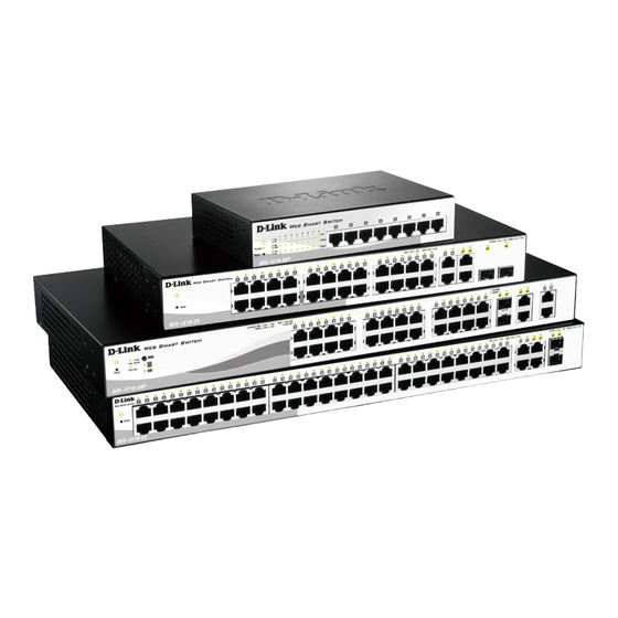
D-Link’s next generation Web Smart Ethernet switch series blends plug-and-play simplicity with exceptional value and reliability for small and medium-sized business (SMB) networking. All models are housed in a new style rack-mount metal case with easy-to-view front panel diagnostic LEDs, and provides advance features including two combo 1000BASE-T/SFP and two additional Gigabit uplinks, network security, traffic segmentation, QoS and versatile management.
Flexible Port Configurations. D-Link Web Smart Switches offer four port configurations, 24/48 Ethernet ports or 8/24 Ethernet ports with PoE support. All ports of the switch support auto MDI/MDIX feature which bring inexpensive and easy Ethernet connection to the desktops. Each switch provides 4 Gigabit uplinks connection to a Gigabit backbone or servers. Two of the Gigabit ports are SFP combo ports which support both 1000M and 100M fiber connections.
Extensive Layer 2 Features. Implemented as complete Layer 2 devices, these switches include functions such as IGMP Snooping, Port Mirroring, Spanning Tree, 802.3ad LACP, SNTP, LLDP and Loopback Detection to enhance performance and network resiliency.
Traffic Segmentation, QoS and Auto Surveillance VLAN. The switches support 802.1Q VLAN standard tagging to enhance network security and performance. The switches also support 802.1p priority queues, enabling users to run bandwidth-sensitive applications such as streaming multimedia by prioritizing that traffic in network. These functions allow switches to work seamlessly with VLAN and 802.1p traffic in the network. Auto Surveillance VLAN will automatically place the vedio traffic from pre-defined IP surveillance devices to an assigned VLAN with higher priority, so it can be separated from normal data traffic. Asymmetric VLAN is implemented in these switches for a more efficient use of shared resources, such as server or gateway devices.
Network Security. D-Link’s innovative Safeguard Engine function protects the switches against traffic flooding caused by virus attacks. Additional feature like 802.1X port-based authentication provides access control of the network with external RADIUS servers. ACL is a powerful tool to screen unwanted IP or MAC traffic. Storm Control keeps the network from being overwhelmed by abnormal traffic. Port Security is another simple but useful authentication method to maintain the integrity of the network device.
Versatile Management. The new generation of D-Link Web Smart Switches provides growing businesses simple and easy management of their network. The SmartConsole utility or a multi-language Web-Based management interface allows administrators to remotely control their network down to the port level. The intuitive SmartConsole easily allows customers to discover multiple D-Link web smart switches in the same L2 network segment. With this utility, users do not need to change the IP address of PC and provides easy initial setting of smart switches. The switches within the same L2 network segment connected to user’s local PC are displayed on the screen for instant access. It allows extensive switch configuration setting, and basic configuration of discovered devices such as a password change or firmware upgrade.
Users can also access the Switch via Telnet. Basic tasks such as changing the Switch IP address, resetting the settings to factory defaults, setting the administrator password, rebooting the Switch, or upgrading the Switch firmware can be performed using the Command Line Interface (CLI).
In addition, users can utilize the SNMP MIB (Management Information Base) to poll switches for information about the status, or send out traps of abnormal events. SNMP support allows users to integrate the switches with other third-party devices for management in an SNMP-enabled environment. D-Link Web Smart Switches also come with the D-View plug-in module that works with D-View 6, SNMP Management Software which provides easy-to-use graphic interface and facilitates the operation efficiency.
2
|
1 Product Introduction |
DES-1210 Series Switch Web UI Reference Guide |
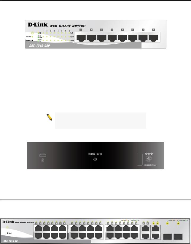
DES-1210-08P
8-Port 10/100Mbps ports Web Smart PoE Switch.
Front Panel
Figure 1.1 – DES-1210-08P Front Panel
Power LED : The Power LED lights up when the Switch is connected to a power source.
Pwr Max: The Pwr Max LED lights up when the Switch reaches the maximum power budget defined by the administrator via PoE System Settings page of Web GUI or the default power budget of 72 Watts.
Reset: By pressing the Reset button the Switch will change back to the default configuration and all changes will be lost.
Mode: By pressing the Mode button, the Port LED will switch between Link/Act and PoE modes.Port Link/Act/Speed LED (1-8): The Link/Act/Speed LED flashes which indicates a network link through the corresponding port. Blinking indicates that the Switch is either sending or receiving data to the port. When a port has amber light indicates that port is running on 10M. When it has a green light it is running on 100M.
NOTE: The installation instructions clearly state that the ITE is to be connected only to PoE networks without routing toe the outside plant.
Rear Panel
Figure 1.2 – DES-1210-08P Rear Panel
Power: The power port is where to connect the AC power cord.
DES-1210-28
24-Port 10/100Mbps with 2 10/100/1000 BASE-T and 2 Combo 1000 BASE-T/SFP Web Smart Switch.
Front Panel
Figure 1.1 – DES-1210-28 Front Panel
Power LED : The Power LED lights up when the Switch is connected to a power source.
Reset: By pressing the Reset button the Switch will change back to the default configuration and all changes will be lost.
3

|
1 Product Introduction |
DES-1210 Series Switch Web UI Reference Guide |
Port Link/Act/Speed LED (1-24): The Link/Act/Speed LED flashes which indicates a network link through the corresponding port. Blinking indicates that the Switch is either sending or receiving data to the port. When a port has amber light indicates that port is running on 10M. When it has a green light it is running on 100M.
Port Link/Act/Speed LED (25, 26, 27T, 28T, 27F, 28F): The Link/Act/Speed LED flashes which indicates a network link through the corresponding port. Blinking indicates that the Switch is either sending or receiving data to the port. When a port has amber light indicates that port is running on 10M or 100M. When it has a green light it is running on 1000M.
NOTE: On DES-1210-28, the MiniGBIC ports are shared with normal RJ-45 ports 27 and 28. When MiniGBIC port is used, the RJ-45 port cannot be used.
CAUTION: The MiniGBIC ports should use UL listed Optical Transceiver product, Rated Laser Class I. 3.3Vdc.
nu
Rear Panel
Figure 1.2 – DES-1210-28 Rear Panel
Power: The power port is where to connect the AC power cord.
DES-1210-28P
24-Port 10/100Mbps PoE ports plus 2 1000Base-T ports and 2 combo SFP/1000Base-T ports Web Smart Switch.
Front Panel
Figure 1.1 – DES-1210-28P Front Panel
Power LED : The Power LED lights up when the Switch is connected to a power source.
Pwr Max: The Pwr Max LED lights up when the Switch reaches the maximum power budget defined by the administrator via PoE System Settings page of Web GUI or the default power budget of 193 Watts.
Reset: By pressing the Reset button the Switch will change back to the default configuration and all changes will be lost.
Mode: By pressing the Mode button, the Port LED will switch between Link/Act and PoE modes.
Port Link/Act/Speed LED (1-24): The Link/Act/Speed LED flashes which indicates a network link through the corresponding port. Blinking indicates that the Switch is either sending or receiving data to the port. When a port has amber light indicates that port is running on 10M. When it has a green light it is running on 100M.
Port Link/Act/Speed LED (25, 26, 27T, 28T, 27F, 28F): The Link/Act/Speed LED flashes which indicates a network link through the corresponding port. Blinking indicates that the Switch is either sending or receiving
4

|
1 Product Introduction |
DES-1210 Series Switch Web UI Reference Guide |
data to the port. When a port has amber light indicates that port is running on 10M or 100M. When it has a green light it is running on 1000M.
NOTE: On DES-1210-28P, the MiniGBIC ports are shared with normal RJ-45 ports 27 and 28. When MiniGBIC port is used, the RJ-45 port cannot be used.
CAUTION: The MiniGBIC ports should use UL listed Optical Transceiver product, Rated Laser Class I. 3.3Vdc.
NOTE: The installation instructions clearly state that the ITE is to be connected only to PoE networks without routing toe the outside plant.
Rear Panel
Figure 1.2 – DES-1210-28P Rear Panel
Power: The power port is where to connect the AC power cord.
DES-1210-52
48-Port 10/100Mbps Web Smart Switch with 2 10/100/1000 BASE-T and 2 Combo 1000 BASE-T/SFP Web Smart Switch.
Front Panel
Figure 1.3 – DES-1210-52 Front Panel
Power LED : The Power LED lights up when the Switch is connected to a power source.
Reset: Press the reset button to reset the Switch back to the default settings. All previous changes will be lost.
Port Link/Act/Speed LED (1-48): The Link/Act/Speed LED flashes which indicates a network link through the corresponding port. Blinking indicates that the Switch is either sending or receiving data to the port. When a port has amber light indicates that port is running on 10M. When it has a green light it is running on 100M.
Port Link/Act/Speed LED (49F, 50F, 49T, 50T, 51, 52): The Link/Act/Speed LED flashes which indicates a network link through the corresponding port. Blinking indicates that the Switch is either sending or receiving data to the port. When a port has amber light indicates that port is running on 10M or 100M. When it has a green light it is running on 1000M.
NOTE: On the DES-1210-52, the MiniGBIC ports are shared with normal RJ-45 ports 49 and 50. When the MiniGBIC port is used, the RJ-45 port cannot be used.
CAUTION: The MiniGBIC ports should use UL listed Optical Transceiver product, Rated Laser
5
![]()
|
1 Product Introduction |
DES-1210 Series Switch Web UI Reference Guide |
Class I. 3.3Vdc.
Rear Panel
Figure 1.4 – DES-1210-52 Rear Panel
Power: Connect the supplied AC power cable to this port.
6
2 Hardware Installation |
DES-1210 Series Switch Web UI Reference Guide |
2 Hardware Installation
This chapter provides unpacking and installation information for the D-Link Web-Smart Switch.
Step 1: Unpacking
Open the shipping carton and carefully unpack its contents. Please consult the packing list located in the User Manual to make sure all items are present and undamaged. If any item is missing or damaged, please contact your local D-Link reseller for replacement.
One D-Link Web-Smart Switch
One AC power cord or one external power adapter
Four rubber feet
Screws and two mounting brackets
One Multi-lingual Getting Started Guide
One CD with User Manual, SmartConsole Utility program, and D-View Module
If any item is found missing or damaged, please contact the local reseller for replacement.
Step 2: Switch Installation
For safe switch installation and operation, it is recommended that you:
Visually inspect the power cord to see that it is secured fully to the AC power connector. Make sure that there is proper heat dissipation and adequate ventilation around the switch. Do not place heavy objects on the switch.
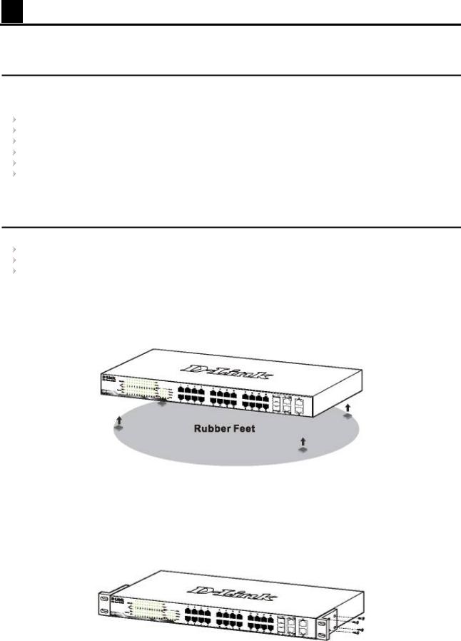
Desktop or Shelf Installation
When installing the switch on a desktop or shelf, the rubber feet included with the device must be attached on the bottom at each corner of the device’s base. Allow enough ventilation space between the device and the objects around it.
Figure 2.1 – Attach the adhesive rubber pads to the bottom
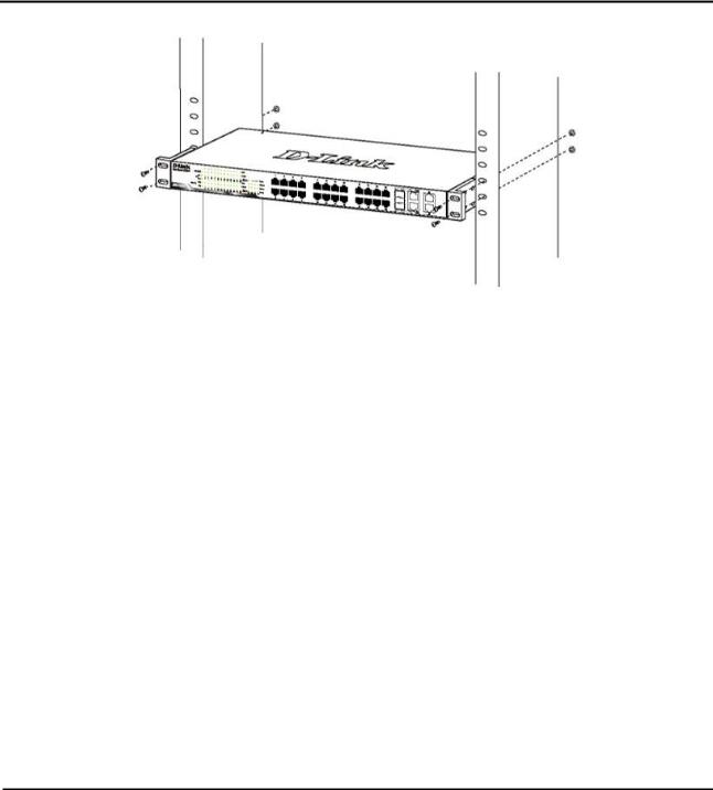
Rack Installation
The switch can be mounted in an EIA standard size 19-inch rack, which can be placed in a wiring closet with other equipment. To install, attach the mounting brackets to the switch’s side panels (one on each side) and secure them with the screws provided (please note that these brackets are not designed for palm size switches).
Figure 2.2 – Attach the mounting brackets to the Switch
7
|
2 Hardware Installation |
DES-1210 Series Switch Web UI Reference Guide |
Then, use the screws provided with the equipment rack to mount the switch in the rack.
Figure 2.3 – Mount the Switch in the rack or chassis
Please be aware of following safety Instructions when installing:
A)Elevated Operating Ambient — If installed in a closed or multi-unit rack assembly, the operating ambient temperature of the rack environment may be greater than room ambient. Therefore, consideration should be given to installing the equipment in an environment compatible with the maximum ambient temperature (Tma) specified by the manufacturer.
B)Reduced Air Flow — Installation of the equipment in a rack should be such that the amount of air flow required for safe operation of the equipment is not compromised.
C)Mechanical Loading — Mounting of the equipment in the rack should be such that a hazardous condition is not achieved due to uneven mechanical loading.
D)Circuit Overloading — Consideration should be given to the connection of the equipment to the supply circuit and the effect that overloading of the circuits might have on overcurrent protection and supply wiring. Appropriate consideration of equipment nameplate ratings should be used when addressing this concern.
E)Reliable Earthing — Reliable earthing of rack-mounted equipment should be maintained. Particular attention should be given to supply connections other than direct connections to the branch circuit (e.g. use of power strips).»
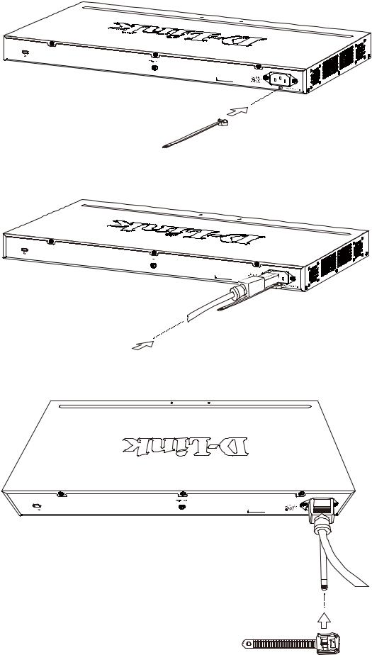
Step 3 – Plugging in the AC Power Cord with Power Cord Clip
To prevent accidental removal of the AC power cord, it is recommended to install the power cord clip together with the power cord.
A) With the rough side facing down, insert the Tie Wrap into the hole below the power socket.
8
|
2 Hardware Installation |
DES-1210 Series Switch Web UI Reference Guide |
||||||||||||||||||||
Figure2.1 – Insert Tie Wrap to the Switch
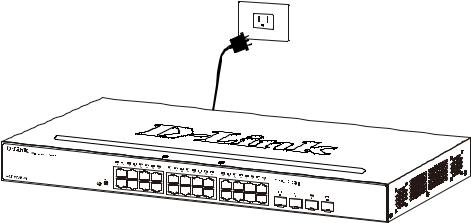
B) Plug the AC power cord into the power socket of the Switch.
Figure 2.2 – Connect the power cord to the Switch
C) Slide the Retainer through the Tie Wrap until the end of the cord.
Figure 2.3 – Slide the Retainer through the Tie Wrap
9

|
2 Hardware Installation |
DES-1210 Series Switch Web UI Reference Guide |
D) Circle the tie of the Retainer around the power cord and into the locker of the Retainer.
Figure 2.4 – Circle around the power cord
E) Fasten the tie of the Retainer until the power cord is secured.
Figure 2.5 – Secure the power cord
F) Users may now connect the AC power cord to an electrical outlet (preferably one that is grounded and surge protected).
10
|
2 Hardware Installation |
DES-1210 Series Switch Web UI Reference Guide |
Figure 2.6 – Plugging the switch into an outlet
Power Failure
As a precaution, the switch should be unplugged in case of power failure. When power is resumed, plug the switch back in.
11

3 Getting Started |
DES-1210 Series Switch Web UI Reference Guide |
3 Getting Started
This chapter introduces the management interface of D-Link Web-Smart Switch.
Management Options
The D-Link Web Smart Switch can be managed through any port on the device by using the Web-based Management or through any PC using the SmartConsole Utility.
Each switch must be assigned its own IP Address, which is used for communication with Web-Based Management or a SNMP network manager. The PC should have an IP address in the same range as the switch. Each switch can allow up to four users to access to the Web-Based Management concurrently.
However, if you want to manage multiple D-Link Web Smart Switches, the SmartConsole Utility is a more convenient choice. By using the SmartConsole Utility, you do not need to change the IP address of your PC and it is easier to initialize multiple Smart Switches.
Please refer to the following installation instructions for the Web-based Management and the SmartConsole Utility.
Using Web-based Management
After a successful physical installation, you can configure the Switch, monitor the network status, and display statistics using a web browser.
Supported Web Browsers
The embedded Web-based Management currently supports the following web browsers: Web Browser via IE8, IE9, Firefox, Chrome and Safari.
Connecting to the Switch
You will need the following equipment to begin the web configuration of your device:
1.A PC with a RJ-45 Ethernet connection
2.A standard Ethernet cable
Connect the Ethernet cable to any of the ports on the front panel of the switch and to the Ethernet port on the PC.
Figure 3.1 – Connected Ethernet cable
Login Web-based Management
In order to login and configure the switch via an Ethernet connection, the PC must have an IP address in the same subnet as the switch. For example, if the switch has an IP address of 10.90.90.90, the PC should have an IP address of 10.x.y.z (where x/y is a number between 0 ~ 254 and z is a number between 1 ~ 254), and a subnet mask of 255.0.0.0. There are two ways to launch the Web-based Management, you may either click
12

|
3 Getting Started |
DES-1210 Series Switch Web UI Reference Guide |
the Web Access button at the top of the SmartConsole Utility or open the web browser and enter 10.90.90.90 (the factory-default IP address) in the address bar. Then press <Enter>.
Figure 3.2 –Enter the IP address 10.90.90.90 in the web browser
NOTE: The switch’s factory default IP address is 10.90.90.90 with a subnet mask of 255.0.0.0 and a default gateway of 0.0.0.0.
The web configuration can also be accessed through the SmartConsole Utility. Open the SmartConsole Utility and double-click the switch as it appears in the Monitor List. This will automatically load the web configuration in your web browser.
When the following logon dialog box appears, enter the password and choose the language of the Webbased Management interface then click OK.
The switch supports 10 languages including English, Traditional Chinese, Simplified Chinese, German, Spanish, French, Italian, Portuguese, Japanese and Russian. By default, the password is admin and the language is English.
Figure 3.3 – Logon Dialog Box
Smart Wizard
After a successful login, the Smart Wizard will guide you through essential settings of the D-Link Web Smart Switch. Please refer to Smart Wizard Configuration section for details.
Web-based Management
By clicking the Exit button in Smart Wizard, you will enter the Web-based Management interface. Please refer to Chapter 4 Configuration for detailed instructions.
D-Link Network Assistant (DNA)
The D-Link Network Assistant (DNA), included in the installation CD, is a program that allows administrators to quickly discover all D-Link smart switches and D-Link Discover Protocol (DDP) supported devices (for a list of supported models, refer to the D-Link Network Assistant (DNA) User Guide), that are in the same subnet as the PC, collect traps and log messages, and provide quick access to basic configurations of the switch. This tool is only for computers running Windows 7, Vista, XP, or 2000 on both 32/64bit systems. There are two options for the installation of the DNA; one is through the Autorun program on the installation CD and the other is manual installation.
NOTE: Please be sure to uninstall any existing
DNA from your PC before installing the latest
DNA.
13

|
3 Getting Started |
DES-1210 Series Switch Web UI Reference Guide |
For detailed explanations of the DNA functions, please refer to D-Link Network Assistant (DNA) User Guide..
14

4 Configuration |
DES-1210 Series Switch Web UI Reference Guide |
4 Configuration
The features and functions of the D-Link Web Smart Switch can be configured for optimum use through the Web-based Management Utility.
Smart Wizard Configuration
After a successful login, the Smart Wizard will guide you through essential settings of the D-Link Web Smart Switch. If you do not plan to change anything, click Exit to leave the Wizard and enter the Web Interface. You can also skip it by clicking Ignore the wizard next time for the next time you logon to the Web-based Management.
IP Information
IP Information will guide you to do basic configurations in 3 steps for the IP Information, access password, and SNMP.
Select Static, DHCP or BOOTP, and enter the desired new IP Address, select the Netmask and enter the Gateway address, then click the Next button to enter the next Password setting page. (No need to enter IP Address, Netmask and Gateway if DHCP and BOOTP are selected.) The Smart Wizard is for the quick setting in IPv4 environment. For IPv6 network, please go to System > IPv6 System Settings. If you are not changing the settings, click Exit button to go back to the main page. Or you can click on Ignore the wizard next time to
skip wizard setting when the switch boots up.
Figure 4.1 – IP Information in Smart Wizard
NOTE: The Smart Wizard supports quick settings for IPv4 network
Password Settings
Type the desired new password in the Password box and again in the Confirm Password, then click the Next button to the SNMP setting page.
15
![]()
|
4 Configuration |
DES-1210 Series Switch Web UI Reference Guide |
Figure 4.2 – Password setting in Smart Wizard
SNMP Settings
The SNMP Setting allows you to quickly enable/disable the SNMP function. The default SNMP Setting is Disabled. Click Enabled and then click Apply to make it effective.
4.3 – SNMP Setting in Smart Wizard
NOTE: Changing the system IP address will disconnect you from the current connection. Please enter the correct IP address in the Web browser again and make sure your PC is in the same subnet with the switch. See Login Webbased Management for a detailed description.
16

|
4 Configuration |
DES-1210 Series Switch Web UI Reference Guide |
If you want to change the IP settings, click OK and start a new web browser.
Figure 4.4 – Confirm the changes of IP address in Smart Wizard
Web-based Management
After clicking the Exit button in Smart Wizard you will see the screen below:
Figure 4.5 – Web-based Management
Above is the Web-based Management screen. The three main areas are the Tool Bar on top, the Function Tree, and the Main Configuration Screen.
The Tool Bar provides a quick and convenient way for essential utility functions like firmware and configuration management.
By choosing different functions in the Function Tree, you can change all the settings in the Main Configuration Screen. The main configuration screen will show the current status of your Switch by clicking the model name on top of the function tree.
At the upper right corner of the screen the username and current IP address will be displayed.
Under the username is the Logout button. Click this to end this session.
NOTE: If you close the web browser without clicking the Logout button first, then it will be seen as an abnormal exit and the login session will still be occupied.
Finally, by clicking on the D-Link logo at the upper-left corner of the screen you will be redirected to the local D-Link website.
17

|
4 Configuration |
DES-1210 Series Switch Web UI Reference Guide |
Tool Bar > Save Menu
The Save Menu provides Save Configuration and Save Log functions.
Figure 4.6 – Save Menu
Save Configuration
Select to save the entire configuration changes you have made to the device to switch’s non-volatile RAM.
Figure 4.7 – Save Configuration
Save Log
Save the log entries to your local drive and a pop-up message will prompt you for the file path. You can view or edit the log file by using text editor (e.g. Notepad).
Figure 4.8 – Save Log
Tool Bar > Tool Menu
The Tool Menu offers global function controls such as Reset, Reset System, Reboot Device, Configuration Backup and Restore, Firmware Backup and Upgrade.
Figure 4.9 – Tool Menu
Reset
Provide a safe reset option for the Switch. All configuration settings in non-volatile RAM will be reset to factory default except for the IP address.
Figure 4.10 – Tool Menu > Reset
Reset System
Provide another safe reset option for the Switch. All configuration settings in non-volatile RAM will be reset to factory default and then the Switch will reboot.
Figure 4.11 – Tool Menu > Reset System
18

|
4 Configuration |
DES-1210 Series Switch Web UI Reference Guide |
Reboot Device
Provide a safe way to reboot the system. Click Apply to restart the switch.
Figure 4.12 – Tool Menu > Reboot Device
Configuration Backup & Restore
Allow the current configuration settings to be saved to a file (not including the password), and if necessary, you can restore configuration settings from the file. Two methods can be selected: HTTP or TFTP.
Figure 4.13 – Tool Menu > Configuration Backup and Restore
HTTP: Backup or restore the configuration file to or from your local drive.
Click Backup to save the current settings to your disk.
Click Browse to browse your inventories for a saved backup settings file.
Click Restore after selecting the backup settings file you want to restore.
TFTP: TFTP (Trivial File Transfer Protocol) is a file transfer protocol that allows you to transfer files to a remote TFTP server. Select IPv4 or IPv6 and specify TFTP Server IP Address and File Name for the configuration file you want to save to / restore from.
Click Backup to save the current settings to the TFTP server.
Click Restore after selecting the backup settings file you want to restore.
Note: Switch will reboot after restore and all current configurations will be lost
Firmware Backup and Upgrade
Allow for the firmware to be saved, or for an existing firmware file to be uploaded to the Switch. Two methods can be selected: HTTP or TFTP.
19
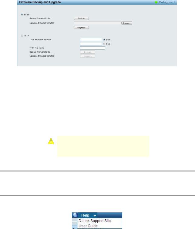
|
4 Configuration |
DES-1210 Series Switch Web UI Reference Guide |
Figure 4.14 – Tool Menu > Firmware Backup and Upgrade
HTTP: Backup or upgrade the firmware to or from your local drive of PC.
Click Backup to save the firmware to your disk.
Click Browse to browse your inventories for a saved firmware file.
Click Upgrade after selecting the firmware file you want to restore.
TFTP: Backup or upgrade the firmware to or from a remote TFTP server. Select IPv4 or IPv6 and specify TFTP Server IP Address and File Name for the configuration file you want to save to / restore from.
Click Backup to save the firmware to the TFTP server.
Click Upgrade after selecting the firmware file you want to restore.
CAUTION: Do not disconnect the PC or remove the power cord from device until upgrade complete. Switch may crash if Firmware upgrade incompletely.
Tool Bar > Smart Wizard
By clicking the Smart Wizard button, you can return to the Smart Wizard if you wish to make any changes there.
Tool Bar > Online Help
The Online Help provides two ways of online support: Online Support Site will lead you to the D-Link website where you can find online resources such as updated firmware images; User Guide can offer an immediate reference for the feature definition or configuration guide.
Figure 4.15 – Online Help
20
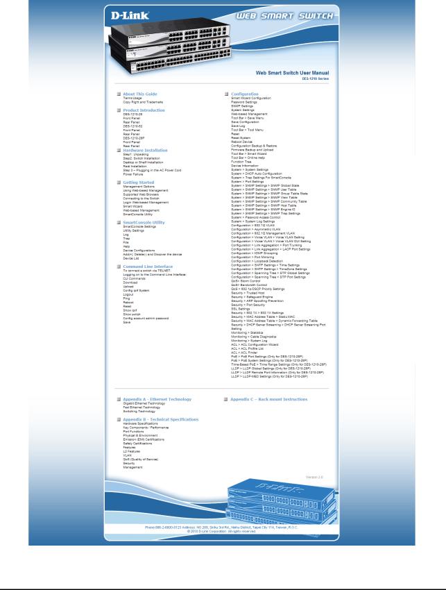
|
4 Configuration |
DES-1210 Series Switch Web UI Reference Guide |
Figure 4.16 – User Guide Micro Site
Function Tree
All configuration options on the switch are accessed through the Setup menu on the left side of the screen. Click on the setup item that you want to configure. The following sections provide more detailed description of each feature and function.
21

|
4 Configuration |
DES-1210 Series Switch Web UI Reference Guide |
Figure 4.17 –Function Tree
Device Information
The Device Information provides an overview of the switch, includes essential information such as firmware & hardware information, and IP address.
It also offers an overall status of common software features:
RSTP: Click Setting to link to L2 Functions > Spanning Tree > STP Global Settings. Default is disabled. Port Mirroring: Click Setting to link to L2 Functions > Port Mirroring. Default is disabled.
Storm Control: Click Setting to link to Security > Storm Control. Default is disabled. DHCP Client: Click Setting to link to System > System Setting. Default is disabled. Jumbo Frame: Click Setting to link to L2 Functions > Jumbo Frame. Default is disabled.
SNMP Status: Click Setting to link to SNMP > SNMP > SNMP Global Setting. Default is disabled. 802.1X Status: Click Setting to link to AAA > 802.1X > 802.1X Settings. Default is enabled. Safeguard Engine: Click Setting to link to Security > Safeguard Engine. Default is enabled.
IGMP Snooping: Click Setting to link to L2 Functions > Multicast > IGMP Snooping. Default is disabled. Power Saving: Click Setting to link to System > Power Saving. Default is enabled.
Figure 4.18 – Device Information
22
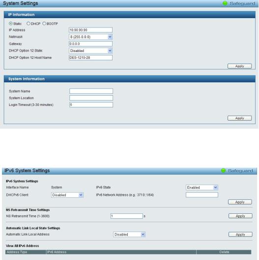
|
4 Configuration |
DES-1210 Series Switch Web UI Reference Guide |
System > System Settings
The System Setting allows the user to configure the IP address and the basic system information of the Switch.
IP Information: There are three ways for the switch to obtain an IP address: Static, DHCP (Dynamic Host Configuration Protocol) and BOOTP.
When using static mode, the IP Address, Subnet Mask and Gateway can be manually configured. When using DHCP mode, the Switch will first look for a DHCP server to provide it with an IP address (including network mask and default gateway) before using the default or previously entered settings. By default the IP setting is static mode with IP address is 10.90.90.90 and subnet mask is 255.0.0.0.
System Information: By entering a System Name and System Location, the device can more easily be recognized from other Web-Smart devices on the LAN.
Login Timeout: The Login Timeout controls the idle time-out period for security purposes, when there is no action for a specific time span in the Web-based Management. If the current session times out (expires), the user is required a re-login before using the Web-based Management again. Selective range is from 3 to 30 minutes, and the default setting is 5 minutes.
Figure 4.19 – System > System Settings
System > IPv6 System Settings
The IPv6 System Settings page allow user to configure the IPv6 system information.
Figure 4.20 – System > IPv6 System Settings
IPv6 System Settings:
Interface Name: Displays the interface name of IPv6.
IPv6 State: Specifies the IPv6 to be enabled or disabled.
23

|
4 Configuration |
DES-1210 Series Switch Web UI Reference Guide |
DHCPv6 Client: Specifies the DHCPv6 client to be enabled or disabled.
IPv6 Network Address: Specifies the IPv6 Network Address.
NS Retransmit Time Settings:
NS Retransmit Time (1-3600): Specifies the NS retransmit time for IPv6. The field range is 1-3600, and default is 1 second.
Automatic Link Local State Settings:
Automatic Link Local Address: Specifies the automatic link is enabled or disabled.
Click Apply for the settings to take effect.
System > IPv6 Route Settings
The IPv6 Route Settings page allows user to configure the IPv6 route settings.
Figure 4.21 – System > IPv6 Route Settings
IP Interface: Specify the IP interface which to be created.
Default Gateway: The corresponding IPv6 address for the next hop Gateway address in IPv6 format..
Metric: Represents the metric value of the IP interface entered into the table. This field may read a number between 1 and 65535.
Click Create to accept the changes made, and click the Delete button to remove the entry.
System > IPv6 Neighbor Settings
The user can configure the Switch’s IPv6 neighbor settings. The Switch’s current IPv6 neighbor settings will be displayed in the table at the bottom of this window.
Figure 4.22 – System > IPv6 Neighbor Settings
Interface Name: Enter the interface name of the IPv6 neighbor.
Neighbor IPv6 Address: Specifies the neighbor IPv6 address.
Link Layer MAC Address: Specifies the link layer MAC address.
Click Apply for the settings to take effect.
24

|
4 Configuration |
DES-1210 Series Switch Web UI Reference Guide |
Interface Name: Specifies the interface name of the IPv6 neighbor. To search for all the current interfaces on the Switch, go to the second Interface Name field in the middle part of the window, tick the All check box. Tick the Hardware option to display all the neighbor cache entries which were written into the hardware table.
State: Use the drop-down menu to select All, Address, Static or Dynamic. When the user selects address from the drop-down menu, the user will be able to enter an IP address in the space provided next to the state option.
Click Find to locate a specific entry based on the information entered.
Click Clear to clear all the information entered in the fields.
System > Password
The Password page allows user to change the login password of the device.
Figure 4.23 – System > Password
To set the Password, set the following parameters and click Apply:
Old Password: If a password was previously configured for this entry, enter it here in order to change it to a new password.
New Password: Enter the new password that you wish to set on the Switch to authenticate users attempting to access Administrator Level privileges on the Switch. The user may set a password of up to 20 characters.
Confirm Password: Confirm the new password entered above. Entering a different password here from the one set in the New Local Enabled field will result in a fail message.
System > Port Settings
In the Port Setting page, the status of all ports can be monitored and adjusted for optimum configuration. By selecting a range of ports (From Port and To Port), the Speed can be set for all selected ports, effective by clicking Apply. Press the Refresh button to view the latest information.
Figure 4.24 – System > Port Settings
25
 Loading…
-
Инструкции по эксплуатации
1

D-Link DES-1210-08P инструкция по эксплуатации
(4 страницы)
- Языки:Русский
-
Тип:
PDF -
Размер:
991.62 KB -
Описание:
Коммутатор
Просмотр
На NoDevice можно скачать инструкцию по эксплуатации для D-Link DES-1210-08P. Руководство пользователя необходимо для ознакомления с правилами установки и эксплуатации D-Link DES-1210-08P. Инструкции по использованию помогут правильно настроить D-Link DES-1210-08P, исправить ошибки и выявить неполадки.