Руководства Daewoo FR-581NW Размер файлов: 5876 KB, Язык: English, Формат: pdf, Платформа: Windows/Linux, Дата: 2015-04-26
На данной странице вы можете скачать руководства Daewoo FR-581NW. Мы предлагаем вам ознакомиться с руководством пользователя, инструкцией по сервисному обслуживанию и ремонту.
Также здесь вы найдете список заказных номеров на комплектующие Daewoo FR-581NW.
Все файлы предоставляются исключительно в ознакомительных целях. И не являютя руководством по ремонту, а направлены лишь на то чтобы помочь вам более детально ознакомиться с принципом построения устройства.
Содержимое представленных здесь руководств требуют от вас знания технического английского языка.
Если вы собираетесь скачать руководство по сервисному обслуживанию Daewoo FR-581NW, иными словами сервис мануал, вы дожны обладать хотя бы минимальными познаниями в области электроники и пониманием базовых принципов работы электромеханических устройств.
Для просмотра руководств вам понадобится Adobe Acrobat Reader версии 9 и выше либо другая программа для просмотра pdf файлов.
В связи с популярностью информации представленной на сайте и ее бесплатного предоставления конечному пользователю, убедительная просьба использовать специальные программные продукты для многопотокового скачивания файлов.
Руководства для Daewoo FR-581NW
- Руководство пользователя (User manual)
- Руководство по сервисному обслуживанию (Service manual)
- Руководство по ремонту (Repair manual)
- Перечень комплектующих (PartList)
- Page / 31
- Table of contents
- BOOKMARKS
Rated. / 5. Based on customer reviews
![]()
-
1
-
2
-
3
-
4
-
5
-
6
-
7
-
8
-
9
-
10
-
11
-
12
-
13
-
14
-
15
-
16
-
17
-
18
-
19
-
20
-
21
-
22
-
23
-
24
-
25
-
26
-
27
-
28
-
29
-
30
-
31
![]()
![]()

Service Manual
Refrigerator
Model: FR-581NT/NW
FR-661NT/NW
DAEWOO ELECTRONICS CO., LTD.
S/M No. : FR581NW010
✔
Caution
: In this Manual, some parts can be changed for improving, their
performance without notice in the parts list. So, if you need the
latest parts information,please refer to PPL(Parts Price List) in
Service Information Center (http://svc.dwe.co.kr).
![]()
Summary of Contents
-
Руководства по ремонту
1

Daewoo FR-581NW сервис-мануал
(31 страница)
-
Тип:
PDF -
Размер:
726.95 KB
Просмотр
Daewoo FR-581NW (Холодильники) сервис мануалы в PDF-формате помогут найти неполадки и ошибки, а также осуществить ремонт Daewoo FR-581NW и восстановить работу устройства.
![]()
S/M No. : FR581NW010
Service Manual
Refrigerator
Model: FR-581NT/NW
FR-661NT/NW
DAEWOO ELECTRONICS CO., LTD.
CONTENTS
|
1. |
Specification ———————————————————————————————— |
1 |
|
2. |
External views——————————————————————————————— |
2 |
|
3. |
Wire diagram ———————————————————————————————- |
3 |
|
4. |
Name of parts———————————————————————————————- |
4 |
|
5. |
Air flow diagram —————————————————————————————— |
5 |
|
6. |
Refrigerant cycle diagram —————————————————————————— |
6 |
|
7. |
Machine room view and part list——————————————————————— |
7 |
|
8. |
Main components ————————————————————————————— |
8 |
|
9. |
Door color specification —————————————————————————— |
12 |
|
10. |
Exploded views and parts list ———————————————————————- |
15 |
|
11. |
Electronic function ———————————————————————————— |
21 |

1. SPECIFICATION
|
MODEL NAME |
FR-581NT/NW |
FR-661NT/NW |
||
|
Refirgerant |
R12 |
200g |
200g |
|
|
R134a |
160g |
160g |
||
|
Cooling System |
Fan Cooling Convection |
|||
|
Refrigeration System |
Air Forced Convection |
|||
|
Defrost System |
Fin Evaporator Forced |
|||
|
Defrost Operation |
Automatic Start & Stop |
|||
|
Cold Control |
Adjustable Button |
|||
|
Freezer |
136 |
153 |
||
|
Capacity |
Refrigerator |
346 |
365 |
|
|
Total |
482 |
518 |
||
|
Height |
1810mm |
1810mm |
||
|
External |
||||
|
Width |
818mm |
818mm |
||
|
Dimension |
||||
|
Depth |
715mm |
770mm |
||
|
Net Weight |
96Kg |
99Kg |
||
1

2. EXTERNAL VIEWS
|
1. FR-581NT/NW |
|||||||
|
24 22 |
810 |
16 |
37 |
53 |
|||
|
810 |
25.5 |
||||||
|
514 |
599 |
||||||
|
590 |
|||||||
|
62 |
|||||||
|
21.8 |
1793.5 |
||||||
|
818.4 |
1015 |
1067 |
|||||
|
141.5 |
762 |
24 |
116.5 |
54.6 |
|||
|
24 |
1.9 |
||||||
|
2. FR-661NT/NW |
|
810 |
16 |
37 |
53 |
|||
|
24 22 |
||||||
|
810 |
25.5 |
|||||
|
514 |
599 |
|||||
|
590 |
||||||
|
62 |
1793.5 |
|||||
|
21.8 |
||||||
|
818.4 |
1015 |
1067 |
||||
|
141.5 |
762 |
116.5 |
1.9 54.6 |
|||
|
24 |
24 |
|||||
|
2 |
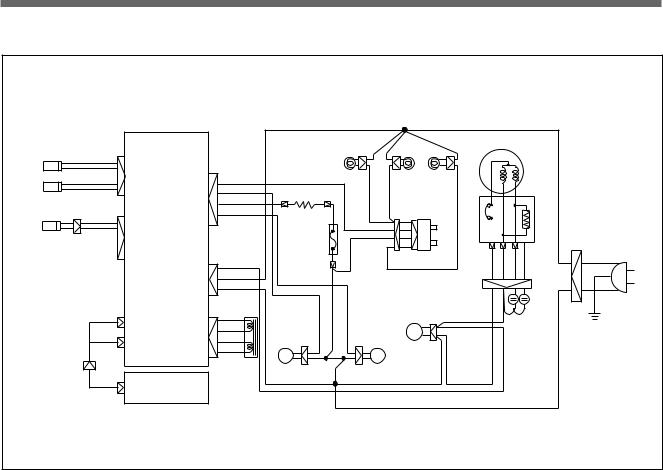
3. WIRE DIAGRAM
|
YELLOW |
YELLOW |
YELLOW |
|||||||||||||
|
YELLOW |
YELLOW |
YELLOW |
COMPRESSOR |
||||||||||||
|
F-SENSOR |
ORANGEX2 |
DOOR S/W |
|||||||||||||
|
RED |
|||||||||||||||
|
BLUEX2 |
RM |
BROWN |
BROWN |
F-LAMP |
M |
A |
|||||||||
|
DEFROST HEATER |
|||||||||||||||
|
D-SENSOR |
BLUE |
DEFROST |
|||||||||||||
|
FM |
WHITE |
HEATER |
BLUE |
||||||||||||
|
GRAY |
BLUE |
||||||||||||||
|
R1-SENSOR |
WHITE |
RED |
|||||||||||||
|
4 |
S/W |
R |
|||||||||||||
|
M-PCB |
|||||||||||||||
|
WHITE |
TEMP |
2 1 3 |
DOOR |
F |
YELLOW |
||||||||||
|
FUSE |
BLACK |
RED ORANGE |
INPUT |
||||||||||||
|
COMP |
RED |
PINK |
|||||||||||||
|
BLACK |
|||||||||||||||
|
220 |
YELLOW |
||||||||||||||
|
BLACK |
|||||||||||||||
|
CCM |
R/C |
BLACK |
|||||||||||||
|
BLACK |
S/C |
POWER |
|||||||||||||
|
RED |
|||||||||||||||
|
BLUE |
RED |
PLUG |
|||||||||||||
|
7P |
BLUE |
||||||||||||||
|
CM |
|||||||||||||||
|
WHITE |
BLUE |
||||||||||||||
|
RED |
|||||||||||||||
|
6P |
BLACK |
RM |
BLACK |
||||||||||||
|
PCB |
BLACK |
FM |
BLACK |
||||||||||||
|
13P |
BLACK |
RED |
|||||||||||||
|
13P |
TRANS |
BLACK |
BLACK |
BLACK |
|||||||||||
|
F-PCB |
|||||||||||||||
|
BLACK |
|||||||||||||||
3

4. NAME OF PARTS |
||||
|
1. FR-581NT, 661NT |
||||
|
1 |
1 |
Freezer Lamp |
||
|
2 |
Freezer Shelf |
|||
|
2 |
3 |
Case Icing |
||
|
3 |
15 |
4 |
Guide Icing |
|
|
5 |
Ice Box |
|||
|
4 |
||||
|
6 |
Chilled Door |
|||
|
5 |
||||
|
7 |
Low Temperature |
|||
|
7 |
||||
|
6 |
16 |
Doodorant |
||
|
8 |
Refrigerator Lamp |
|||
|
8 |
17 |
9 |
Refrigerator Shelf |
|
|
10 Crisper Cover |
||||
|
18 |
||||
|
9 |
11 Criper (A) |
|||
|
12 |
Criper (B) |
|||
|
19 |
13 Front Grille |
|||
|
14 Adjustable Foot |
||||
|
10 |
15 Freezer Pocket |
|||
|
16 Egg Pocket |
||||
|
11 |
17 Egg Tray |
|||
|
12 |
20 |
18 Refrigerator Pocket |
||
|
19 Bottle Pocket |
||||
|
13 |
20 Multi Pocket |
|||
|
14 |
||||
|
2. FR-581NW , 661NW |
||||
|
1 |
Freezer Lamp |
|||
|
1 |
2 |
Freezer Shelf |
||
|
3 |
Case Icing |
|||
|
2 |
||||
|
4 |
Guide Icing |
|||
|
3 |
||||
|
15 |
5 |
Ice Box |
||
|
4 |
||||
|
6 |
Low Temperature |
|||
|
5 |
Deodorant |
|||
|
6 |
16 |
7 |
Chilled Door |
|
|
7 |
8 |
Refrigerator Lamp |
||
|
9 |
Refrigerator Shalf |
|||
|
8 |
||||
|
10 Crisper Cover |
||||
|
17 |
11 Front Grille |
|||
|
9 |
12 Adjustable Foot |
|||
|
13 |
Crisper (A) |
|||
|
18 |
||||
|
14 Crisper (B) |
||||
|
10 |
15 Freezer Pocket |
|||
|
19 |
16 |
Water Tank |
||
|
17 Egg Tray |
||||
|
18 Egg Pocket |
||||
|
19 Bottle Pocket |
||||
|
11 |
20 |
20 Multi Pocket |
||
|
12 |
13 |
14 |
||
|
4 |
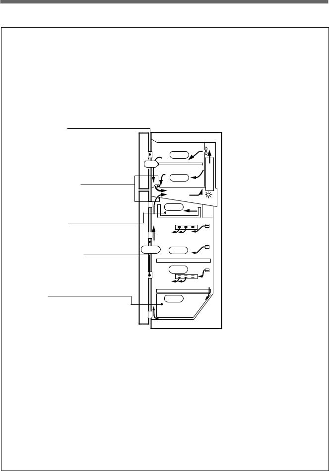
5. AIR FLOW DIAGRAM
Freezer pocket
Please don’t put long term storing items such as ice cream etc.
It might be melted because of opening the door frequently.
Inlet of cooling air
It should not be blocked with food etc. as it is the inlet where cooling air returns.
Chilled room
It is good for the storage of fishes and meats.
Refrigerator pocket
It is good for the storage of beer and beverage etc.
Crisper
It is suitable to store vegetable and fruit.
The moisture panel which is attached to the cover maintains the humidity properly.
Vegetable and fruit would be better to be packed with clean wrap foils.
|
-19 |
|
|
-19 |
|
|
-19 |
|
|
-1~1 |
|
|
3~6 |
1~3 |
|
1~3 |
|
|
3~5 |
Freezer
Please don’t put bottles such as beer, beverage etc. It might be broken because of freezing.
Multiple outlet of cooling air
Please don’t put in vegetable etc, which contain moisture. It might be frozen because of low temperature.
5
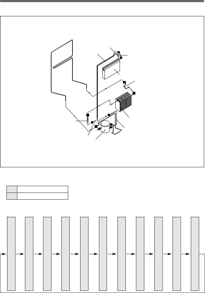
6. REFRIGERANT CYCLE DIAGRAM
-PIPE HOT
ACCUM
SUCC.PIPE
EVA.
PIPE CON (A)
|
DRYER AS |
WI-CON. |
|
|
PIPE CON (S) |
||
|
CAPI-TUBE |
DELIVERY PIPE |
|
|
COMP |
Welding Specifications
¡WELD 5% SILVER
§WELD 35% SILVER
Freezing Cycle
|
C |
D |
H |
P |
W |
D |
C |
E |
A |
S |
P |
|
|
O |
E |
O |
I |
I |
R |
A |
V |
C |
U |
I |
|
|
M |
L |
T |
P |
Y |
P |
A |
C |
C |
P |
||
|
P |
I |
E |
C |
E |
I |
P |
U |
T |
E |
||
|
R |
V |
P |
R |
L |
|||||||
|
O |
O |
N |
I |
||||||||
|
E |
E |
I |
L |
||||||||
|
C |
N |
R |
U |
O |
c |
||||||
|
S |
R |
P |
A |
||||||||
|
O |
A |
L |
N |
o |
|||||||
|
S |
Y |
E |
R |
||||||||
|
O |
N |
P |
T |
A |
n |
||||||
|
Y |
|||||||||||
|
R |
P |
(A) |
I |
O |
T |
P |
(S) |
||||
|
pressure |
I |
P |
T |
R |
O |
I |
pressure |
||||
|
P |
|||||||||||
|
E |
U |
R |
P |
||||||||
|
E |
|||||||||||
|
B |
E |
||||||||||
|
E |
|||||||||||
|
High |
Low |
||||||||||
|
6 |
§
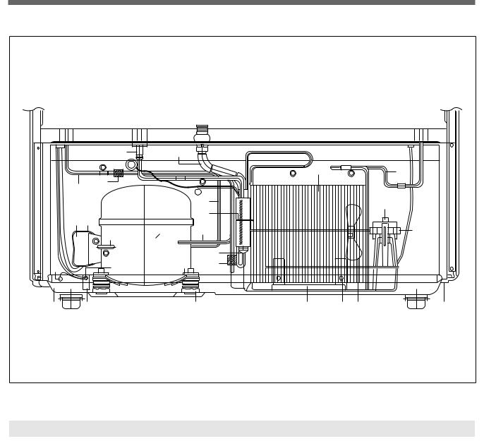
7. MACHINE ROOM VIEW AND PART LIST
|
11 |
22 |
|||||
|
9 |
8 |
|||||
|
17 |
||||||
|
7 |
||||||
|
6 |
1 |
|||||
|
15 16 |
4 |
|||||
|
12 |
||||||
|
2 |
19 |
|||||
|
5 |
||||||
|
10 |
||||||
|
25 |
27 |
14 |
18 |
|||
|
13 |
26 |
3 |
23 |
24 |
20 |
21 |
|
NO |
PART NAME |
NO |
PART NAME |
NO |
PART NAME |
|
1 |
FIXTURE C MOTOR AS |
10 |
DRYER |
19 |
MOTOR C |
|
2 |
PIPE SERVICE |
11 |
PIPE SUCTION AS |
20 |
FAN |
|
3 |
ABSORBER |
12 |
PIPE SUC CONN |
21 |
BOLT SPECIAL |
|
4 |
CABLE TIE |
13 |
BASE COMP AS |
22 |
HOSE DRN B |
|
5 |
COMPRESSOR |
14 |
WASHER SPECIAL |
23 |
CASE VAPORI |
|
6 |
PIPE CONN A |
15 |
SWITCH P-RELAY AS |
24 |
SCREW TAPPING |
|
7 |
PIPE HOT |
16 |
CLAMP BAND RELAY |
25 |
SCREW MACHINE |
|
8 |
PIPE CONN B |
17 |
ABSORBER PIPE B |
26 |
CORD POWER AS |
|
9 |
PIPE WICON AS |
18 |
ABSORBER PIPE A |
27 |
SCREW TAPPING |
7
8.MAIN COMPONENTS
1.COMPRESSOR
|
Refrigerant |
R12 |
|||||||
|
Voltage |
100V/50,60Hz |
110V/60Hz |
115, 120V/60Hz |
127V/60Hz |
220V/50Hz |
220V/60Hz |
230V/50Hz |
240V/50Hz |
|
Comp. model |
X |
BL27YE-3 |
BL25YG-2 |
SL28YE-5 |
PL25YG-4 |
SL28YE-5 |
||
|
Part code |
X |
3952127A30 |
3952125Q20 |
3954128A50 |
3956125Q40 |
3954128A50 |
||
|
Strating type |
X |
CSR |
CSR |
RSIR |
RSCR |
RSIR |
||
|
Refrigerant |
R134a |
|||||||||
|
Voltage |
100V/50,60Hz |
110V/60Hz |
115, 120V/60Hz |
127V/60Hz |
220V/50Hz |
220V/60Hz |
230V/50Hz |
240V/50Hz |
||
|
Comp. model |
X |
HBL27YE-3 |
HBL25YG-2 |
HSL27YE-5 |
X |
HSL27YE-5 |
||||
|
Part code |
X |
3952127G30 |
3952125G20 |
3954128G50 |
X |
3954128A50 |
||||
|
Strating type |
X |
CSR |
CSR |
RSIR |
X |
RSIR |
||||
|
2. RELAY ASSSEMBLY |
||||||||||
|
Refrigerant |
R12 |
|||||||||
|
Voltage |
100V/50,60Hz |
110V/60Hz |
115, 120V/60Hz |
127V/60Hz |
220V/50Hz |
220V/60Hz |
230V/50Hz |
240V/50Hz |
||
|
Relay model |
X |
444THBZZ-52 |
414THBYY-52 |
276THBYY-52 |
213THBYY-52 |
276THBYY-52 |
||||
|
Part code |
X |
3018111900 |
3018112510 |
3018112800 |
3018110900 |
3018112800 |
||||
|
Refrigerant |
R134a |
|||||||||
|
Voltage |
100V/50,60Hz |
110V/60Hz |
115, 120V/60Hz |
127V/60Hz |
220V/50Hz |
220V/60Hz |
230V/50Hz |
240V/50Hz |
||
|
Relay model |
X |
783RHBZZ-52 |
427THBZZ-52 |
276THBYY-52 |
X |
276THBYY-52 |
||||
|
Part code |
X |
3018112700 |
3018112520 |
3018112800 |
X |
3018112900 |
3018112800 |
|||
|
3. RUNNING CAPACITOR |
||||||||||
|
Refrigerant |
R12 |
|||||||||
|
Voltage |
100V/50,60Hz |
110V/60Hz |
115, 120V/60Hz |
127V/60Hz |
220V/50Hz |
220V/60Hz |
230V/50Hz |
240V/50Hz |
||
|
Spec. |
X |
230V/10µF |
300V/7µF |
X |
350V/5µF |
X |
X |
|||
|
Part code |
X |
400EL15130 |
386100400 |
X |
400EL15110 |
X |
X |
|||
|
Refrigerant |
R134a |
|||||||||
|
Voltage |
100V/50,60Hz |
110V/60Hz |
115, 120V/60Hz |
127V/60Hz |
220V/50Hz |
220V/60Hz |
230V/50Hz |
240V/50Hz |
||
|
Spec. |
X |
230V/10µF |
300V/7µF |
X |
X |
X |
X |
|||
|
Part code |
X |
400EL15130 |
386100400 |
X |
X |
X |
X |
|||
8
 Loading…
 Loading…
S/M No. : FR581NW010
Service Manual
Refrigerator
Model: FR-581NT/NW
FR-661NT/NW
✔ Caution
: In this Manual, some parts can be changed for improving, their
performance without notice in the parts list. So, if you need the
latest parts information,please refer to PPL(Parts Price List) in
Service Information Center (http://svc.dwe.co.kr).
DAEWOO ELECTRONICS CO., LTD.
CONTENTS
1. Specification -----------------------------------------------------------------------------------------------1
2. External views---------------------------------------------------------------------------------------------2
3. Wire diagram ----------------------------------------------------------------------------------------------3
4. Name of parts----------------------------------------------------------------------------------------------4
5. Air flow diagram -----------------------------------------------------------------------------------------5
6. Refrigerant cycle diagram -----------------------------------------------------------------------------6
7. Machine room view and part list--------------------------------------------------------------------7
8. Main components --------------------------------------------------------------------------------------- 8
9. Door color specification ------------------------------------------------------------------------------12
10. Exploded views and parts list ----------------------------------------------------------------------15
11. Electronic function ------------------------------------------------------------------------------------21
1. SPECIFICATION
MODEL NAME
Refirgerant
FR-581NT/NW
FR-661NT/NW
R12
200g
200g
R134a
160g
160g
Fan Cooling Convection
Cooling System
Refrigeration System
Air Forced Convection
Defrost System
Fin Evaporator Forced
Defrost Operation
Automatic Start & Stop
Cold Control
Freezer
Capacity
Refrigerator
Total
External
Dimension
Net Weight
346
482
136
Adjustable Button
365
518
153
Height
1810mm
1810mm
Width
818mm
818mm
Depth
715mm
770mm
96Kg
99Kg
1
1793.5
599
514
24 22
24
762
762
24
2
1.9
1067
1015
1793.5
21.8
62
590
599
514
24 22
25.5
16
54.6
53
810
37
2. FR-661NT/NW
53
116.5
24
37
16
141.5
818.4
810
54.6
1067
62
25.5
24
1.9
116.5
1015
590
810
141.5
21.8
810
818.4
2. EXTERNAL VIEWS
1. FR-581NT/NW
3. WIRE DIAGRAM
YELLOW
YELLOW
6P
PCB
TRANS
13P
F-PCB
YEL
LOW
R/C
S/C
RED
CM
RED
FM
BLACK
BLACK
BLACK
BLACK
BLACK
BLACK
BLACK
3
YELLOW
F
BLACK
RED
ORANGE
PINK
BLACK
RM
R
INPUT
BLACK
BLUE
BLUE
WHITE
BLACK
7P
13P
TEMP
FUSE
RED
YELLOW
BLACK
M A
RED
COMP
220
CCM
RED
BLACK
RED
M-PCB
DOOR S/W
WHITE
2 1 3 4
WHITE
F-LAMP
BROWN
DEFROST
HEATER
COMPRESSOR
BLUE
R1-SENSOR
BROWN
BLUE
WHITE
RED
BLUE
D-SENSOR
Y
GRAY
BLUEX2
DOOR S/W
RM
DEFROST HEATER
FM
W
BLACK
ORANGEX2
BLUE
F-SENSOR
YELLOW
YELLO
OW
ELL
POWER
PLUG
4. NAME OF PARTS
1. FR-581NT, 661NT
1
2
3
4
5
7
15
6
16
8
17
18
9
19
10
11
20
12
13
1
2
3
4
5
6
7
8
9
10
11
12
13
14
15
16
17
18
19
20
Freezer Lamp
Freezer Shelf
Case Icing
Guide Icing
Ice Box
Chilled Door
Low Temperature
Doodorant
Refrigerator Lamp
Refrigerator Shelf
Crisper Cover
Criper (A)
Criper (B)
Front Grille
Adjustable Foot
Freezer Pocket
Egg Pocket
Egg Tray
Refrigerator Pocket
Bottle Pocket
Multi Pocket
14
2. FR-581NW , 661NW
1
2
3
15
4
1
2
3
4
5
6
5
16
6
7
8
17
9
18
10
19
20
11
12
13
14
4
7
8
9
10
11
12
13
14
15
16
17
18
19
20
Freezer Lamp
Freezer Shelf
Case Icing
Guide Icing
Ice Box
Low Temperature
Deodorant
Chilled Door
Refrigerator Lamp
Refrigerator Shalf
Crisper Cover
Front Grille
Adjustable Foot
Crisper (A)
Crisper (B)
Freezer Pocket
Water Tank
Egg Tray
Egg Pocket
Bottle Pocket
Multi Pocket
5. AIR FLOW DIAGRAM
Freezer pocket
Please don't put long term storing
items such as ice cream etc.
It might be melted because of
opening the door frequently.
-19
-19
-19
Inlet of cooling air
It should not be blocked with food
etc. as it is the inlet where cooling
air returns.
-1~1
Chilled room
It is good for the storage of fishes
and meats.
Refrigerator pocket
It is good for the storage of beer
and beverage etc.
Freezer
Please don't put bottles
such as beer, beverage etc.
It might be broken
because of freezing.
3~6
1~3
1~3
Crisper
It is suitable to store vegetable and
fruit.
The moisture panel which is
attached to the cover maintains the
humidity properly.
Vegetable and fruit would be better
to be packed with clean wrap foils.
3~5
5
Multiple outlet of cooling air
Please don't put in vegetable
etc, which contain moisture.
It might be frozen because of
low temperature.
6. REFRIGERANT CYCLE DIAGRAM
IPE
T-P
HO
ACCUM
SUCC.PIPE
I-PIPE
EVA.
PIPE CON (A)
WI-CON.
DRYER AS
PIPE CON (S)
DELIVERY PIPE
CAPI-TUBE
COMP
✦ Welding Specifications
¡
WELD 5% SILVER
§
WELD 35% SILVER
✦ Freezing Cycle
P
I
P
E
H
O
T
P
I
P
E
P
I
P
E
C
O
N
(A)
W
I
C
O
N
D
R
Y
E
R
P
I
P
E
C
A
P
I
L
L
A
R
Y
T
U
B
E
6
E
V
A
P
O
R
A
T
O
R
A
C
C
U
N
U
L
A
T
O
R
S
U
C
T
I
O
N
P
I
P
E
P
I
P
E
c
o
n
(S)
Low pressure
D
E
L
I
V
E
R
Y
High pressure
C
O
M
P
R
E
S
S
O
R
7. MACHINE ROOM VIEW AND PART LIST
22
11
9
8
17
7
6
4
15 16
1
12
2
19
5
25
13
NO
27
10
18
14
26
3
23
24 20
21
PART NAME
NO
PART NAME
NO
PART NAME
1
FIXTURE C MOTOR AS
10
DRYER
19
MOTOR C
2
PIPE SERVICE
11
PIPE SUCTION AS
20
FAN
3
ABSORBER
12
PIPE SUC CONN
21
BOLT SPECIAL
4
CABLE TIE
13
BASE COMP AS
22
HOSE DRN B
5
COMPRESSOR
14
WASHER SPECIAL
23
CASE VAPORI
6
PIPE CONN A
15
SWITCH P-RELAY AS
24
SCREW TAPPING
7
PIPE HOT
16
CLAMP BAND RELAY
25
SCREW MACHINE
8
PIPE CONN B
17
ABSORBER PIPE B
26
CORD POWER AS
9
PIPE WICON AS
18
ABSORBER PIPE A
27
SCREW TAPPING
7
8. MAIN COMPONENTS
1. COMPRESSOR
Refrigerant
Voltage
R12
100V/50,60Hz 110V/60Hz
Comp. model
X
BL27YE-3
Part code
X
3952127A30
Strating type
X
CSR
115, 120V/60Hz
127V/60Hz
220V/50Hz
220V/60Hz
230V/50Hz
BL25YG-2
SL28YE-5
PL25YG-4
SL28YE-5
3952125Q20 3954128A50 3956125Q40 3954128A50
CSR
RSIR
RSCR
RSIR
127V/60Hz
220V/50Hz
220V/60Hz
230V/50Hz
HBL25YG-2
HSL27YE-5
X
HSL27YE-5
X
3954128A50
RSIR
X
RSIR
220V/50Hz
220V/60Hz
230V/50Hz
Refrigerant
Voltage
240V/50Hz
R134a
100V/50,60Hz 110V/60Hz
Comp. model
X
HBL27YE-3
Part code
X
3952127G30
Strating type
X
CSR
115, 120V/60Hz
3952125G20 3954128G50
CSR
240V/50Hz
2. RELAY ASSSEMBLY
Refrigerant
Voltage
R12
100V/50,60Hz 110V/60Hz
115, 120V/60Hz
127V/60Hz
Relay model
X
444THBZZ-52
414THBYY-52 276THBYY-52 213THBYY-52 276THBYY-52
Part code
X
3018111900
3018112510 3018112800 3018110900 3018112800
Refrigerant
Voltage
240V/50Hz
R134a
100V/50,60Hz 110V/60Hz
115, 120V/60Hz
127V/60Hz
220V/50Hz
220V/60Hz
230V/50Hz
240V/50Hz
Relay model
X
783RHBZZ-52
427THBZZ-52 276THBYY-52
X
276THBYY-52
Part code
X
3018112700
3018112520 3018112800
X
3018112900 3018112800
Refrigerant
Voltage
Spec.
Part code
100V/50,60Hz 110V/60Hz
X
230V/10µF
X
400EL15130
115, 120V/60Hz
R12
127V/60Hz 220V/50Hz
300V/7µF
X
386100400
X
220V/60Hz
350V/5µF
400EL15110
230V/50Hz
X
X
240V/50Hz
X
X
Refrigerant
Voltage
Spec.
Part code
100V/50,60Hz 110V/60Hz
X
230V/10µF
X
400EL15130
115, 120V/60Hz
R134a
127V/60Hz 220V/50Hz
300V/7µF
X
386100400
X
220V/60Hz
X
X
230V/50Hz
X
X
240V/50Hz
X
X
3. RUNNING CAPACITOR
8
4. STARTING CAPACITOR
Refrigerant
Voltage
Spec.
Part code
100V/50,60Hz 110V/60Hz 115, 120V/60Hz
X
200V/100µF
X
3016400100
R12
127V/60Hz 220V/50Hz
X
X
220V/60Hz
350V/25µF
400EL16110
230V/50Hz
X
X
240V/50Hz
X
X
Refrigerant
Voltage
Spec.
Part code
100V/50,60Hz 110V/60Hz 115, 120V/60Hz
X
200V/100µF
X
3016400100
R134a
127V/60Hz 220V/50Hz
X
X
220V/60Hz
X
X
230V/50Hz
290V/50 µF
4124G62020
240V/50Hz
X
X
240V/50Hz
5. F-FAN MOTOR
Refrigerant
Voltage
R12, R134a
100V/50,60Hz 110V/60Hz
Spec.
X
Part code
X
115, 120V/60Hz
127V/60Hz
220V/50Hz
220V/60Hz
230V/50Hz
ORM-1001L1
ORM-1001D1
ORM-1001B2
ORM-1005B1
ORM-1001H2
IS-3211DWBFN
IS-3211DWBFV IS-23211DWBFR IS-23211DWBFJ IS-3211DWBFT
3015902520
3015902530
3015902540
3015902510
3015902550
6. R-FAN MOTOR
Refrigerant
Voltage
R12, R134a
100V/50,60Hz 110V/60Hz
Spec.
X
Part code
X
115, 120V/60Hz
127V/60Hz
220V/50Hz
220V/60Hz
230V/50Hz
ORM-1002L1
ORM-1002D1
ORM-1002B2
ORM-1006B1
ORM-1002H2
IS-3211DWBFM
IS-3211DWBFU IS-3211DWBFQ IS-23211DWBFE IS-3211DWBFS
3015902620
3015902630
3015902640
3015902610
3015902650
240V/50Hz
7. C-FAN MOTOR
Refrigerant
Voltage
R12, R134a
100V/50,60Hz 110V/60Hz
115, 120V/60Hz
127V/60Hz
220V/50Hz
220V/60Hz
230V/50Hz
Spec.
X
RF111EAC03
RF111SAC03
RF111BAC03
RF111GAC03
RF111HAC03
Part code
X
3015902720
3015902730
3015902740
3015902700
3015902750
220V/60Hz
230V/50Hz
240V/50Hz
8. DEFROST HEATER
Refrigerant
Voltage
R12, R134a
100V/50,60Hz 110V/60Hz
115, 120V/60Hz
127V/60Hz
220V/50Hz
Spec.
X
180W
180W
Part code
X
3010006721
3010006711
9
240V/50Hz
9. LAMP ASSEMBLY
Refrigerant
Voltage
R12, R134a
100V/50,60Hz 110V/60Hz
115, 120V/60Hz
127V/60Hz
220V/50Hz
Spec.
X
120V/15W
240V/15W
Part code
X
3013600010
3013600030
220V/60Hz
230V/50Hz
240V/50Hz
220V/60Hz
230V/50Hz
240V/50Hz
5EPK057720
5EPK041005
230V/50Hz
240V/50Hz
10. PCB TRANSFORMER
Refrigerant
Voltage
Part code
R12, R134a
100V/50,60Hz 110V/60Hz
X
115, 120V/60Hz
5EPK041004
127V/60Hz
220V/50Hz
5EPK057800
5EPK042000
11. MAIN PCB ASSEMBLY
Refrigerant
Voltage
R12, R134a
100V/50,60Hz 110V/60Hz
115, 120V/60Hz
Spec.
X
N805
Part code
X
3014353010
127V/60Hz
220V/50Hz
220V/60Hz
3014363010
12. DRYER
Refrigerant
R12
R134a
Spec.
10 g
15 g
3016802100
3016801211
Part code
10
POWER CORD SPECIFICATION
NO
SHAPE OF POWER CODE
PART CODE
DESCRIPTION
1
3011315000
CP-2PIN
FOR EUROPEAN COUNTRY
2
401RA17200
CP-2PIN
FOR OTHER COUNTRY
3
4006D17101
KP-30
FOR AMERICA
4
401PD17101
KP-211
FOR JAPAN & TAIWAN
5
3011300801
BP-3PIN
6
3011303010
#267
7
3011315310
8
3011303050
BS-1363A
FOR U.K, MIDDLE ASIA
SINGAPORE & MALAYSIA
9
3011301200
KP-551/550
FOR CHINA & AUSTRALIA
FOR CHILE
FOR ISRAEL
* Upper power cord’s part code is only for lead wire, without any kinds of terminal or housing.
11
REMARK
9. DOOR COLOR SPECIFICATION
1. ASSEMBLY URETHAN FREEZER DOOR
Refrigerant
Color type
R12
Dull lamina
High glossy
sheet
lamina sheet
X
X
Part code
R134a
Normal PCM
X
High glossy
Dull lamina
High glossy
bright PCM
sheet
lamina sheet
PWFT006A40
X
X
Normal PCM
X
High glossy
bright PCM
PWFT006A50
2. ASSEMBLY URETHAN REFRIGERATOR DOOR
1) FR-581NT, 661NT
Refrigerant
Color type
Part code
R12
Dull lamina
High glossy
sheet
lamina sheet
X
X
R134a
Normal PCM
X
High glossy
Dull lamina
High glossy
bright PCM
sheet
lamina sheet
PWRT006A40
X
X
Normal PCM
X
High glossy
bright PCM
PWRT006A50
2) FR-581NW, 661NW
Refrigerant
Color type
Part code
R12
Dull lamina
High glossy
sheet
lamina sheet
X
X
R134a
Normal PCM
X
High glossy
Dull lamina
High glossy
bright PCM
sheet
lamina sheet
PWRT006A60
X
X
12
Normal PCM
X
High glossy
bright PCM
PWRT006A70
COLOR TABLE
1. PCM type
NO
COLOR CHIP
COLOR NAME
1
P/WITH (WH069)
2
'94 L/GRAY (GY158)
3
'95 L/GRAY (GY259)
4
'94 M/GRAY (GY331)
5
'95 M/GRAY (GY335)
6
'97 M/GRAY (GY267)
7
M. D/GRAY (GY750)
8
N/BLUE (BL718)
9
MINT GREEN (GN206)
10
'97 BEIGE (BE215)
13
2. Lamina sheet type
NO
COLOR CHIP
COLOR NAME
1
P/WITH (WH069)
2
'94 L/GRAY (GY158)
3
'95 L/GRAY (GY259)
4
'94 M/GRAY (GY331)
5
'95 M/GRAY (GY335)
6
'97 M/GRAY (GY267)
7
M. D/GRAY (GY750)
8
N/BLUE (BL718)
9
MINT GREEN (GN206)
10
S/GOLD
11
G/GREEN
14
10. EXPLODED VIEWS AND PARTS LIST
1. FR-581NT, 661NT
1. Exploded views
15
2. Parts list
✔ Caution : In this Service Manual, some parts can be changed for improving, their performance without notice in the parts list.
So, if you need the latest parts information, please refer to PPL (Parts Price List) in Service Information Center
(http://svc.dwe.co.kr)
NO
PART NAME
PART CODE
FR-581NT
FR-661NT
DESCRIPTION
Q'ty
REMARK
1
ASSY CAB URT
2
HOSE DRAIN (B)
3013202200
3
BASE COMP AS
3010309100
1
3-1
PIPE WI-CON AS
3014415500
1
3-2
MOTOR C AS
3-3
FAN
3011800400
3-4
FIXTURE C MOTOR AS
3012006000
3-5
CASE VAPORI
3011111700
PP
1
3-6
SCREW TPPING
7112401211
T1 TRS 4 x 12 MFZN
2
4
SPECIAL BOLT
3016003300
T2 6.5 x 20
4
5
FOOT *F *L AS
3012700700
1
6
FOOT *F *R AS
3012100600
1
7
BOLT HEX
3016000700
8
ABSORBER COMP AS
3010101440
9
COMPRESSOR
1
REFER TO # 8
10
SWITCH P RELAY AS
1
REFER TO # 8
11
RELAY BAND
3816100100
SK-5 T0.7
1
12
SPECIAL WASHER
3016002500
SK-5 T0.8
4
13
DRYER AS
14
ASSY R*S LUVR *L
3010028804
3010028814
1
15
ASSY R*S LUVR *R
3010028822
3010028832
1
15-1
SENSOR R1 AS
3014701140
16
DUCT CHILD AS
3010029532
SOCKET R LAMP AS
3017900860
250V/1A
1
17
SCREW TAPPING
7112401611
T2 TRS 4 x 16 MFZN
3
18
LAMP AS
19
WINDOW R
3015501600
20
SWITCH DR
3018100020
21
CASE DEO AS
3011101800
21-1
CASE DEO AS
3011102501
21-2
DEODORANT
3018700600
21-3
SEALING DEO
3017714600
21-4
DEODERANT SHEET
3018700700
22
HINGE *M AS
3012904800
SCP-1 T3.21
1
23
SPECIAL BOLT *M
3016001220
6B-1 6 x 20
3
24
COVER *M HI
3014424700
ABS
1
25
MOTOR F AS
16-1
25-1
FAN
1
PP
1
1
ABS ( 0 110mm)
REFER TO # 9
1
1
M6 x 15
2
4
1
REFER TO # 10
1
3011128931
1
2
3015500800
GPPS
1
2BUTTON/4PIN
1
1
PP
1
1
F-US
1
1
1
3011800400
ABS ( 0 110mm)
16
1
REFER TO # 10
NO
PART NAME
PART CODE
FR-581NT
DESCRIPTION
FR-661NT
Q'ty
25-2
MOUSE BELL
3018500100
HIPS
1
25-3
COVER MOTOR C
4017Z32233
HIPS
1
25-4
ABSORBER MOTOR
4017Z08430
EPR-B3(H40)
1
25-5
MOTOR F
25-6
COVER MOTOR B
4017Z32244
HIPS
1
25-7
FIXTURE FAN
4004Q10060
STS27
1
26
SCREW TAPPING
7112401611
T2S TRS 4 x 16 MFZN
2
27
MOTOR R AS
1
MOTOR R
1
27-1
1
28
SCREW TAPPING
7112401611
29
COVER F M/F DUCT A
3011406600
29-1
SOCKET *F LAMP AS
3017900820
29-2
LAMP AS
3011414300
T2S TRS 4 x 16 MFZN
2
ABS
1
250V/1A
1
1
REMARK
REFER TO # 9
REFER TO # 9
REFER TO # 10
30
SCREW TAPPING
7112401611
T1 TRS 4 x 12 MFZN
2
31
WINDOW F
3015500400
GPPS
1
32
BRACKET F SENS
4017Z29010
SCP-1 T3.2
1
33
INSULATOR F LOUVER AS
3013321400
F-PS
1
34
LOUVER F AS
3018903400
PP
1
35
ASSY *U HI
3010010700
35-1
WASHER PLAIN
7400108511
PW-1-8.5
1
36
SPECIAL BOLT
3016001201
6B-1 6 x 20
4
37
HINGE *T AS
3012904700
38
SPECIAL BOLT T/U
3016001230
6B-1 6 x 20
4
39
COVER *T HI
3011432900
PP
1
40
BOX M/PCB
3010511700
PP
1
41
TRANS POWER
1
REFER TO # 10
42
CAPACITOR
1
REFER TO # 8
43
PCB MAIN AS
1
REFER TO # 10
44
SCREW TAPPING
7112401211
T1 TRS 4 x 12 MFZN
3
45
COVER M/PCB BOX
3011425300
PP
1
46
COVER CUBIC/C
3011424400
ABS
4
47
ASSY R DR TOTAL
48
GASKET R DR AS
3012305000
PVC+MAGNET
1
49
HANDLE R DR
3012605100
ABS+CR
1
50
SCREW TAPPING
7112401611
T2S TRS 4 x 16 MFZN
3
51
DECORATOR R DR HANDLE
3011601800
ABS
1
52
POCKET SM
3019002301
GP
2
53
POCKET JUMBO
3018000500
GP
1
54
POCKET M
3019000901
GP
1
55
ASSY F DR TOTAL
1
1
1
1
17
REFER TO # 12
REFER TO # 12
NO
PART NAME
PART CODE
FR-581NT
DESCRIPTION
FR-661NT
Q'ty
56
GASKET F DR AS
3012304800
PVC+MAGNET
1
57
HANDEL F DR
3012605000
ABS+CR
1
58
SCREW TAPPING
7112401611
T2S TRS 4 x 16 MFZN
3
59
DECORATOR F DR HANDLE
3011601700
ABS
1
60
PANEL F*T
3014203600
1
60-1
PANEL F CONTROL
3014203500
1
60-2
PCB *F AS
3014351110
1
60-3
SCREW TAPPITE
7173301011
TT2 BIN 3 x 10 MFZN
1
60-4
BUTTON FCP
3016300700
ABS+CR
2
61
SCREW TAPPING
7125401213
T2S FLT 4 x 16 MFCR
2
62
PLATE FCP NAME
3014512100
PC-FILM T0.5
1
63
PLATE NAME TANK
3014512500
ABS+CR
1
64
CASE VEGETB A
3011104500
SAN
1
65
CASE VEGETB B
3011101300
SAN
1
66
POCKET F *T
3019001801
GP
2
67
SUPOTR VEGETB COVER
3015301003
SAN
1
68
COVER V/CASE
3011407001
3011404701
SAN
1
69
SHELF R AS
3010051200
3010051100
SAN
2
70
CASE CHILD
3011105200
SAN
1
71
DOOR CHILD CASE
3011716700
SAN
1
72
SHELF F
3017808300
3017808400
SAN
1
73
GUIDE ICING
3011403600
3012504300
HIPS
1
74
CASE ICING
3011106100
PP
2
75
BOX ICE CASE
4010E99100
76
CASE EGG
3011107900
77
CORD POWER AS
78
SCREW TAPPING
7112401211
79
GRILLE
3012400100
80
SCREW TAPPING
7112401211
T1 TRS 4 x 12 MFZN
5
81
FOOT ADJ AS
3012100400
PP
2
82
COVER CAB BRKT
3011425100
PP
1
83
SCREW TAPPING
7112401211
T1 TRS 4 x 12 MFZN
2
84
EVAPORATOR
3017000923
85
FUSE TEMP AS
3017200101
86
ASSY D HTR
1
86-1
HEATER D AS
1
86-2
COVER HTR *T
3011408201
AL 1200P-H24 T0.4
1
86-3
COVER HTR *U
3011408100
AL 1200P-H24 T0.4
1
REMARK
1
SAN
2
1
T1 TRS 4 x 12 MFZN
3012400600
REFER TO # 11
1
1
1
SW-103T (77°C )
18
1
REFER TO # 9
2. FR-581NW, 661NW
1. Exploded views
19
2. Parts list
✔ Caution : In this Service Manual, some parts can be changed for improving, their performance without notice in the parts list.
So, if you need the latest parts information, please refer to PPL (Parts Price List) in Service Information Center
(http://svc.dwe.co.kr)
NO
PART NAME
PART CODE
FR-581NW
FR-661NW
3010054901
3010054910
DESCRIPTION
Q'ty
16
DUCT CHILD AS
47
ASSY R DR TOTAL
76
CASE EGG
3011107410
SAN
2
87
POCKET EGG
3019005110
GP
3
88
WINDOW W/D AS
3015502400
89
COVER WATER ACEPT
3011412910
90
FIXTURE LEVER AS
3012003600
91
SCREW TAPPING
7112401311
MFZN
2
92
SHAFT OUTLET
3014900600
ABS
1
93
SPRING DISPENSER
3015100100
SUS 304 ¯0.9
1
94
CAP OUTLET
3010922700
ABS
1
95
PACKING W/TANK
3014001500
SILICON
1
96
PACKING CAP A
3014001000
SILICON
1
97
PACKING CAP B
3014001010
SILICON
1
98
CAP W/TANK A
3010914100
ABS
1
99
CAP W/TANK B
3010914200
ABS
1
100
TANK W/D
30182002100
PE
1
1
1
1
ABS+GOLD
1
1
* All other parts except the above part list are same as 581NT and 661NT.
The exploded view may be a little different in shapes from the NT type standard type.
20
REMARK
REFER TO # 12
11. ELECTRONIC FUNCTION
1. N805
1) How to use the panel
1. Pressing once
1) Temperature regulation of both compartments.
2) Other LEDs are in ordinary state.
3) Fuzzy (button) does not work.
4) Quick FRZ. button : Temperature regulation of freezer
E.F ➝ 1 ➝ 2 ➝ 3 ➝ E.F
5) Quick REF. button : Temperature regulation of
refrigerator (fresh-food compartment)
E.F ➝ 1 ➝ 2 ➝ 3 ➝ E.F
2. Pressing twice
1) Temperature regulation of both compartments (freezer
& refrigerator) finished.
2) Returns to ordinary state.
3) No flicker of LED.
• BAR LEDs light on 3 times.
• FUZZY icon lights on.
• FUZZY canceled, if buttoned again.
• Both compartments’ LEDs of “E.F”, “E.R”,
“1”, “2”, “3” go off.
FUZZY
2 3
Q.F FRZ.
FUZZY
QUICK FRZ.
FRZ. SET
1
REF. Q.R
C
SURROUND
E.F
TEMP SET
1
QUICK REF.
REF. SET
REGULAR
E.R
• BAR LEDs lights on 3 times.
• LEDs of freezer (“E.F”, “1”, “2”, “3”) go off.
• QUICK LED lights on.
• Refrigerator LEDs are in ordinary state.
• Buttoned again, then canceled.
3 2
• BAR LEDs lights on 3 times.
• LEDs of freezer (“E.R”, “1”, “2”, “3”) go off.
• QUICK LED lights on.
• Freezer LEDs are in ordinary state.
• Buttoned again, then canceled.
21
2) Function table
NO.
1
Control
Function
Freezer
temperature
control
Control
Objects
COMP.
F-fan
R-fan
C-fan
LED
Contents
Remark
1. If press the temperature set button, then freezer temperature
range will blink. During blinking, press the quick freezer/freezer
set button.
E.F ➝ 1 ➝ 2 ➝ 3 ➝ E.F
FUZZY
2 3
Q.F
FRZ.
FUZZY
QUICK FRZ.
FRZ. SET
REF. Q.R
˚C
SURROUND
E.F
1
3 2
TEMP SET
1
QUICK REF.
REF. SET
REGULAR
E.R
2. COMP. F-fan controlled by on/off point of each temperature
range.
3. Freezer temperature on/off difference is 5˚C.
4. Temperature(˚C)/Resistance(kΩ)
COMP. on
COMP. off
E.R
-15.5/17.5
-20.5/23.0
1
-16.5/18.4
-21.5/24.3
2
-17.5/19.5
-22.5/25.7
3
-18.5/20.6
-24.5/28.8
5. Bar LED is irrelevant with COMP. on/off.
6. In case of temperature requlation in the middle of fuzzy, fuzzy
is canceled and temperation is done.
2
Fridge
temperature
control
COMP.
R-fan
C-fan
LED
1. If press the temperature set button, then fridge temperature
range will blink. During blinking, press the quick fridge/fridge
set button press.
E.R ➝ 1 ➝ 2 ➝ 3 ➝ E.R
FUZZY
2 3
Q.F
FRZ.
QUICK FRZ.
FRZ. SET
1
REF. Q.R
˚C
FUZZY
SURROUND
3 2
TEMP SET
1
QUICK REF.
REF. SET
REGULAR
E.F
E.R
2. R-fan controlled by on/off point of each temperature range.
3. Fridge temperature on/off difference is 0.35˚C.
4. Temperature(˚C)/Resistance(kΩ).
R-fan. on
R-fan. off
E.R
1.35/28.4
1.0/28.7
1
0.35/29.7
0.0/30.0
2
-0.65/30.9
-1.0/31.4
3
-2.65/33.8
-3.0/34.3
5. Prevention of weak fridge.
1) When weak fridge temperature(7˚C) is sensed, COMP. is on.
2) When R1-sensor value reaches R-fan off point COMP. is
controlled by F-sensor.
3) R1-sensor detects and cancels weak fridge.
22
NO.
Control
Function
Control
Objects
Contents
Remark
6. Bar LED is irrelevant with R-fan on/off.
7. In case of temperature requlation in the middle of fuzzy, fuzzy
is canceled and temperation is done.
3
Quick
freezing
COMP.
F-fan
C-fan
LED
1. Quick freezing mode is started by pressing quick freeze button.
FUZZY
2 3
Q.F
FRZ.
FUZZY
QUICK FRZ.
FRZ. SET
SURROUND
3 2
TEMP SET
1
QUICK REF.
REF. SET
REGULAR
E.F
1
REF. Q.R
˚C
E.R
2. When quick freeze is done, COMP., F-fan, C-fan are on for
150 min. regardless of F-sensor.
3. Quick freezing is possible in fuzzy mode.
4
Quick
fridge
COMP.
R-fan
C-fan
LED
1. Quick fridge mode is started by pressing quick refrigerate
button.
FUZZY
2 3
Q.F
FRZ.
FUZZY
QUICK FRZ.
FRZ. SET
1
REF. Q.R
˚C
SURROUND
E.F
3 2
TEMP SET
1
QUICK REF.
REF. SET
REGULAR
E.R
2. Quick freezing is possible in fuzzy mode.
3. Temperature graph in quick fridge is as follow.
TEMP
ON LOW('1)
OFF RUNNING
ON HIGH("3")
OFF RUNNING
OFF-POINT
OF OVER
REFRIGERATION
QUICK(40min)
TIME
1) R-fan and COMP. are on until the R1-sensor value reaches
the point of over fridge temperature(-7˚C)
2) After the over fridge temperature, ‘3’(high) is done until the
quick fridge ends(40 min.).
3) Ordinary state starts after quick fridge.
23
NO.
5
Control
Function
Fuzzy
Control
Objects
COMP.
R-fan
F-fan
C-fan
LED
Contents
Remark
1. Fuzzy mode is started by pressing fuzzy button.
FUZZY
2 3
Q.F
FRZ.
FUZZY
QUICK FRZ.
FRZ. SET
1
REF. Q.R
˚C
SURROUND
3 2
TEMP SET
1
QUICK REF.
REF. SET
REGULAR
E.F
E.R
2. Fuzzy mode is canceled by pressing fuzzy button once again.
3. Prediction cooling is applied to both compartment.
1) In case of frequent door opening is ‘3’(high).
2) In case of less frequent door opening is ‘2’(middle).
6
Determination
defrost
1. How to determin defrost mode.
1) Accumulated running time of COMP.
2) Running ratio of COMP.
3) Accumulated time of door opening
4) Total time(On time of COMP.+Off time of COMP.)
5) Outside temperature.
6) D, F RT, R1-sensor and door switch error.
2. Starting conditions of defrost mode.
Start
2
4
6
8
10
(Accumulated running time of COMP.)
1) When the accumulated time is 6, 8, 10, defrost starts.
2) If the accumulated time is more than 10, defrost mode
starts unconditionally.
7
Defrost
mode
COMP.
R-fan
F-fan
C-fan
Heater
1. Pre-cool
1) Time is 50 min.
2) COMP. and F-fan is on.
3) If the F-sensor ≤ -27˚C even the time elapsed is less than 50
min., the Pre-cool step goes off.
2. R-fan defrost
1) Time is 10 min.
2) Only R-fan is on.
3) If D-sensor ≥10˚C, R-fan will be off and jump to pause step.
24
NO.
Control
Function
Control
Objects
Contents
Remark
3. Heater defrost
1) If D-senso r ≥10˚C, Heater is off.
2) Limited time is 80 min.
4. Pause
1) Time is 4 min.
2) COMP. F-fan, R-fan are off.
5. Fan delay
1) Time is 5 min.
2) COMP. and C-fan are on.
6. Time table.
R-fan
defrost
off
off
on
off
10 min.
Pre-cool
COMP.
F-fan
R-fan
Heater
Limited time
8
Demo
function
R-fan
F-fan
on
on
control
off
50 min.
Heater
defrost
off
off
off
on
80 min.
Pause
Fan delay
off
off
off
off
4 min.
on
off
off
off
5 min.
1. If CN10 terminal on the M-PCB is shorted, all electric devices
are off except F-fan and R-fan.
2. Fan control table.
Normal status
Demo status
Door open
F, R-fan : off
F, R-fan : on
Door close
F, R-fan : on
F, R-fan : off
3. F-PCB indicates the normal status and fuzzy status alternately.
FRZ.
2 3
REF.
3 2
C
FUZZY
SURROUN
REGULAR
E.F
1
E.R
1
Normal status
FRZ.
2 3
REF.
3 2
C
FUZZY
SURROUN
REGULAR
E.F
1
E.R
Fuzzy status
25
1
NO.
9
Control
Function
Electric
device
delay
Control
Objects
Door S/W
COMP.
R-fan
F-fan
Contents
Remark
1. F-fan on or off time is delayed, when COMP. is on or off.
ON
COMP
OFF
ON
F-FAN
OFF
1MIN.
1MIN.
2. F-fan and R-fan on or off time is delayed, when door switch is
on or off.
CLOSE
OFF
OFF
OPEN
DOOR S/W
ON
F-FAN
ON
R-FAN
0.5SEC 0.5SEC
10
Inital
defrost
COMP.
R-fan
F-fan
C-fan
Heater
1. If D-sensor ≤ 3.5˚C in initial power supply, it enters to defrost
mode.
11
Delivery
function
COMP.
F-fan
R-fan
C-fan
Heater
1. If press the quick freezing and quick refrigerating button for 3
sec., before power on, then delivery function will start.
FUZZY
2 3
Q.F
FRZ.
QUICK FRZ.
FRZ. SET
1
REF. Q.R
˚C
FUZZY
SURROUND
E.F
3 2
TEMP SET
1
QUICK REF.
REF. SET
REGULAR
E.R
2. The electric devices are off for 3 hours in deliverry function.
3. The custom LED is on normally.
12
COMP.
restart
prevent
COMP.
1. After COMP. is off, the COMP. is not on even though the Fsensor is at on point for 6 min.
13
COMP.
restart
prevent
COMP.
1. Alarm buzzes 3 sec. after initial power on.
2. Alarm buzzes whenever each switch in F-PCB is pressed.
3. If the door is opened for more than 1 min., chirpy sound alarm
buzzes.
4. If adjust temperature, the fuzzy button will be not operative
and the buzzer will be off.
26
NO.
14
Control
Function
Forced
defrost
Control
Objects
COMP.
F-fan
R-fan
Heater
Contents
Remark
1. Press the quick freezing button 5 times, when press the fuzzy
button. After that can enter the forced defrost mode.
FUZZY
2 3
Q.F
FRZ.
QUICK FRZ.
FRZ. SET
REF. Q.R
˚C
FUZZY
SURROUND
E.F
1
3 2
TEMP SET
1
QUICK REF.
REF. SET
REGULAR
E.R
2. Forced defrost mode.
1) The Pre-cool step is omitted.
2) Start from R-fan defrost.
15
Adjust
R1-sensor
off point
1. When the temperature in fridge room is low (Low temperature
even though R-fan and COMP. are operating properly),
following functions are operating for easy after service.
1)
R13 : Off point determination in
normal operation
R14 : Decreases off point
determination
J15 : If remove J1, the off point
will be decreased.
R1-SENSOR
R13
J15
R14
2) Resistance value
R13 : 31. 4 kΩ
R14 : 2.15 kΩ
3) Off point temperature
Off point temperature
16
Error
display
LED
J15 shorted
-1.0˚C
J15 opened
-2.5˚C
1. Press the fuzzy button 3 times. When press the quick freezing
and the quick refrigeration button. After that error mode.
FUZZY
2 3
Q.F
FRZ.
QUICK FRZ.
FRZ. SET
1
REF. Q.R
˚C
FUZZY
SURROUND
3 2
TEMP SET
1
QUICK REF.
REF. SET
REGULAR
E.F
E.R
2. All the custom LED are off, unless there is error.
3. If any error, relevant LED lights on.
4. Press the fuzzy button 3 times again. When press the quick
freezing and the quick refrigeration button. After that error
mode is canceled.
5. All error code will be reset, if they become normal.
6. Error code is refered to 3) Self-diagnosis table.
27
3) Self-diagnosis table
Code
F 1 (FRZ.)
Defect function
F-sensor
Check method
- Compressor & F-fan is on for 24 minutes.
- Compressor & F-fan is off for 16 minutes.
R 1 (REF.)
R1-sensor
- Regarded by R2-sensor.
R 2 (Q.R)
R2-sensor
- Detecting weak cooling is impossible.
D 1 (E.R)
D-sensor
- Heater is on only for 35 minutes.
RT (E.R)
RT-sensor
D 0 (1 Fridge)
Door switch
C 1 (2 Fridge)
Cooling cycle
(check after first
defrost mode)
F 3 (3 Fridge)
Heater
- Natural defrost for 80 minutes.
➧ If both R1 and R2-sensor are out of order, then RT-sensor control R-fan.
- Room temperature ≤ 14˚C : R-fan is off
- Room temperature ≥ 26˚C : R-fan is on for 15 minutes, R-fan is off for 5 minutes
- 14˚C < Room temperature < 26˚C : R-fan is on for 2 minutes, R-fan is off for 18 minutes
28
4) Circuit and wiring diagram
TD623088B
F-PCB
7
6
2
3
M-PCB
R52
R53
CN01
D1 D2 D3 D4
CN06
1
15
14
10
11
4
9
VDD
1
16
4
2
13
SW3 SW1 SW2 SW4
D5 D6
3
SET
Fuzzy
FRZ
CC20
2
F/E
3
F/L
1K
R02
R/M
FRZ
R/E 6
7
S/M 7
FR
8
9
Fuzzy
Q.R
Q.F
S/M 8
FR
4
9
5
10
10
11
3
1,
2
11
12
6
13
7
8
7
SCAN D
F-S
CC22
0.1µF
+
CE02
CC14
12
13
R1-S
10
9
11
8
12
7
13
6
14
5
15
4
16
3
17
2
18
1
16
DATA
R43
15
R44
14
R11
30.1K
R45
13
R46
12
R47
11
DATA
10
DATA
9
DATA
R48
R49
W
R14
2.15K
+
CE04
TEMP
3˚C
5˚C
7˚C
5.00V
M5.00ms Ch1
5.9V
POWER CORD
CN01
:2mV
:-2mV
RT-SENSOR
26
+CE06
D4
1N4002
IC02
+
R17
CC18
S JAM 1996
11:41:07
220V AC
DATA
RT-S
R21
jump
10K
open
PCB TRANS
1
27
DATA
DATA
DATA
R20
open
10K
jump
R1-SENSOR
2
R2-S
C1 RMS
14.20V
4. The DIODE which has not been
displayed its model name is IN 4148.
R12
28
CC16
R42
D-SENSOR
5.
R13
31.4K
+
CE03
:2mV
:-2mV
3. The CONDENSER which has not been
displayed time constant is 10µF.
CN05
R09
25.7K
R10
29
4M
R41
F-SENSOR
R08
30
KEY INPUT
CN07
REF
SCAN C
L
8
CC09
F/H 5
R/L
O
42
CC15
1K
R40
CC23
R/H
SCAN B
6
D-S
1K
R01
4
F/M
SCAN A
5
CC21
5
REF
6
1
8
IC07
4
D7 D8
2. The CERAMIC CONDENSOR which
been displayed time constant is 0.01µF.
R51
CC12
0.1µF
5
12
1. The RESISTOR value which has not
displayed time constant is 10K 1/4W.
CN04
CN01
R50
7812
CE07
R18
15K
+
BL
W
G
+
CE08
1000µF
CC01
IC01
L
BD1
C1 RMS
14.20V
Y
L
IC08
TD62783AP
BL
FUSE 1.5A
Fuzzy 11
B
3
5V
17
D1
1N4148
RESET
R-S
OVERCOOL
3
19
a4 5
b1
b2
b3
c1
c2
c3
c4 7
d1
d2
d3
d4 8
e1
e2
e3
e4 9
XIN
XIN
7
D-HTR
RE TURN
20
21
R25
CN03
f2
f3
f4 10
g2
g3
g4 11
COMP
VAREF
R
RY1
22
V
Vss
SS
13
3
14
4
16
03
15
04
FREQ
CHECK
15
5
16
6
17
7
18 VCC
8
9
R05
CC10
31
R28
04
13
05
12
06
11
14
05
13
06
12
07
11 10
08 GND
CN08
07 COM
10
9
COM 04
16 15
14
14
& GND
13 12
13
11
2
DEMO S/W
HTR
F-FAN
BUZZER
R-FAN
1
IC05
3
13
4
14
5
15
6
16
7
8
17 GND
1
2
VCC 01
3
4
5
6
11 HEAT SINK 12
& GND
7
8
02 VCC
16
38
2
37
3
4
35
5
34
6
33
7
10
36
8
9
:1V
:-101V
RY2
BZI
RY3
15
14
13
F-FAN
12
VAR2
R32
750ohm
11
IC06
2
3
3
9
R34
R33
3
4
1
2
CC13
PC817
29
02
IC04
3
MC03
R37
11
4
DOOR S/W 32
CHECK
C1 RMS
59.6V
C-FAN
POWER OFF
CHECK
TMP87CH46N
2
12
FUSE TEMP
UT-205
CC08
03 COM
10
9
4.7K
CC06
4.7K
R31
COMP
R07
CC07
1
11
Delete
Rets
70+/-5˚C
R29
3 ‰ˆ £· ˆ
KEY
TD62308BP (LOW INPUT ACTIVE 1.5A DRIVER)
HEAT SINK
ULN2004A
03
14
UT-205
R30
TD62783AP (DARLINGTON DRIVER)
02
15
Save Vim
Ch1
S/C
DEFORST
HEATER GY
39
R06
01
16
P
W
+ CE09
CC05
1
17
02
File
Utiles
P-RELAY
13
SW01
18
01
Save formal
Mgthcee
ReCall
from file
R/C
L
XOUT
R04
12
2
ReCall
Wavelorm
CHGND
12
11
1
:2mV
:-2mV
C1 RMS
245.4mV
BR
VS-12MB
R27
30.1K
CC04
ULN2004A
f1
F-ROOM
240V 13W
BL
R26
19.6K
R
g1
S JAM 1996
11:41:07
W
R
R24
31.4K
23
(8MHz)
b4 6
R-ROOM
Y
CC11
4
a3
400mV
CN02
R23
18
R2
BL
R21
R22
24
CE01
a2
4L
CC19
R03
6
CN01
R19
25
41
CC24
2
CC02
0.1µF
R20
R-S
OVERWARM
M5.00mm Ch1
VAR1
CC03
40
1
a1
10.0V
7805
TEST
JIG-PCB
1
V
IC03
9,10 12
S/M
R39 NC02
15
R38 MC01
14
1
S/W
DOOR
03
1N5399
R35
47K
R36
47K
Ch1
50.0V
50.0V
5.00mm
M5.00mm
Ch1
-14V
8 JAN 1995
11:51:38