-
Contents
-
Table of Contents
-
Bookmarks
Quick Links
User Guide
Controller for appliance control
AK-CC 550A
ADAP-KOOL® Refrigeration control systems
Related Manuals for Danfoss AK-CC 550A
Summary of Contents for Danfoss AK-CC 550A
-
Page 1
User Guide Controller for appliance control AK-CC 550A ADAP-KOOL® Refrigeration control systems… -
Page 2
• Integrated MODBUS communication with the option of mount- Appliance examples ing a LonWorks communication card Contents Introduction ………………….. 2 Operation ………………….26 Operation ………………….4 Menu survey …………………28 Applications …………………12 Connections …………………32 Survey of functions ………………15 Data ……………………34 Ordering ………………….35 Manual RS8FS402 © Danfoss 2016-03 AK-CC 550A… -
Page 3
Here temperature is always controlled using the S4 temperature. The two S3 temperatures are used for alarm monitoring and display readings for each refrigeration section. There are common alarm limits for the two refrigeration section. AK-CC 550A Manual RS8FS402 © Danfoss 2016-03… -
Page 4
Minimum and maximum limits can be set for alarm temperature and time delays. A longer time delay can be set for high temperature alarm. This time delay is active after defrosting, appliance cleaning and start-up. Manual RS8FS402 © Danfoss 2016-03 AK-CC 550A… -
Page 5
The cooling appliance is stopped like the “Main switch”, but this happens without an “A45 standby alarm”. The function can be enabled by a switch on the DI input or via a setting through data communication. AK-CC 550A Manual RS8FS402 © Danfoss 2016-03… -
Page 6
(though, not with application 6) or via a parameter setting. All the mentioned methods can be used at random – if just of them is activated a defrost will be started. Manual RS8FS402 © Danfoss 2016-03 AK-CC 550A… -
Page 7
The refrigeration will then be stopped during the set melting period. The frost will be melted so that the air flow and hence the evaporator’s capacity will be greatly improved. AK-CC 550A Manual RS8FS402 © Danfoss 2016-03… -
Page 8
In the area between the two dew point values the controller will manage the power to be supplied to the rail heat. Dew point During defrosting During defrosting rail heat will be active, as selected in setting d27. Manual RS8FS402 © Danfoss 2016-03 AK-CC 550A… -
Page 9
A setting can define that the night blind is open when «r12» (Main switch) is set to off (see o98). When the night blind rolls down, the fan will be stopped for 2 minutes. The night blind can thereby roll down to the correct position. AK-CC 550A Manual RS8FS402 © Danfoss 2016-03… -
Page 10
To prevent that the heating Heat thermostat cuts in during short-term drops in air temperature a time delay can be set for when to change from refrigeration to heating. Manual RS8FS402 © Danfoss 2016-03 AK-CC 550A… -
Page 11
The controller contains a number of functions which can be used together with the override function in the master gateway/system manager. Function via data communication Function in gateway/system manager Used parameters in AK-CC 550A Start of defrosting Defrost control / Time schedule / Defrost group — Def start… -
Page 12
Application 1-4 Standard applications. This is for standard use where the vital difference is only different combinations of the following functions/outputs: • Alarm • Rail heat • Compressor • Light Manual RS8FS402 © Danfoss 2016-03 AK-CC 550A… -
Page 13
S4 temperature. The product sensor is used as an extra S3 sensor for section no. 2. Alarm monitoring and display readings take place individually via the «S3» sensors in each refrigeration section. AK-CC 550A Manual RS8FS402 © Danfoss 2016-03… -
Page 14
It is only the lower sign that needs to be mounted. The number is indicated on the left-hand side of the signs. Use the sign with the current application number. One of the signs applies to both applications 4 and 10. Manual RS8FS402 © Danfoss 2016-03 AK-CC 550A… -
Page 15
Here you define the sensor the thermostat is to use for its control function. S3, S4, or a combination of them. With the setting 0%, only S3 is used (Sin). With 100%, only S4. AK-CC 550A Manual RS8FS402 © Danfoss 2016-03… -
Page 16
A cut-out/cut-in input will result in alarm when the time delay has been passed. The function is defined in o02. Delay of a DI2 alarm AI.Delay DI2 A cut-out/cut-in input will result in alarm when the time delay has been passed. The function is defined in o37 Manual RS8FS402 © Danfoss 2016-03 AK-CC 550A… -
Page 17
2 = Gas Defrost stop temperature Def. Stop Temp The defrost is stopped at a given temperature which is measured with a sensor (the sensor is defined in d10). The temperature value is set. AK-CC 550A Manual RS8FS402 © Danfoss 2016-03… -
Page 18
4: All schedules are carried out + extra if it is registered that it is required. (Reset: Temporary setting to 0 will reset the recorded values and start a new calcula- tion of the evaporator air flow.) Manual RS8FS402 © Danfoss 2016-03 AK-CC 550A… -
Page 19
In the event of a power failure of less than four hours, the clock function will be saved. Clock: Hour setting Clock: Minute setting Clock: Date setting Clock: Month setting Clock: Year setting AK-CC 550A Manual RS8FS402 © Danfoss 2016-03… -
Page 20
Warning: Wrong selection of refrigerant may cause damage to the compressor. Other refrigerants: Here Setting 13 is selected and then three factors -Ref.Fac a1, a2 and a3 — via AKM must be set. Manual RS8FS402 © Danfoss 2016-03 AK-CC 550A… -
Page 21
0 and 100. If not, you can cancel the function with setting 0. If the function is used, access code 1 (o05) must also be used. AK-CC 550A Manual RS8FS402 © Danfoss 2016-03… -
Page 22
Light and night blinds definition Light MS = Off 0: Light is switched off and night blinds are open when the main switch is off 1: Light and night blinds are independent of main switch. Manual RS8FS402 © Danfoss 2016-03 AK-CC 550A… -
Page 23
DI3 status Status on input DI3 (on/1 = 230 V) Cutin temp. Readout of the actual cutin value for the thermostat Cutout temp. Readout of the actual cut out value for the thermostat AK-CC 550A Manual RS8FS402 © Danfoss 2016-03… -
Page 24
*) Emergency cooling will take effect when there is lack of signal from a defined S3 or S4 sensor or signal from the pressure transmitter is outside signal range.. The regulation will continue with a registered average cutin frequency. There are two registered values – one for day operation and one for night operation. Manual RS8FS402 © Danfoss 2016-03 AK-CC 550A… -
Page 25
The importance of individual alarms can be defined with a setting. The setting must be carried out in the group «Alarm destinations» Settings from Settings from Alarm relay Send via High Low-High System manager AKM (AKM destination) Network High Middle Log only Disabled AK-CC 550A Manual RS8FS402 © Danfoss 2016-03… -
Page 26
Reading the temperature at defrost sensor (Or product sensor, if selected in o92.) • A short press of the lower button Manuel start or stop of a defrost • Push the lower button for four seconds. (not application 6) Manual RS8FS402 © Danfoss 2016-03 AK-CC 550A… -
Page 27
Sensor signal for display view S4% (017) Note: For applications 9 and 10 the sensor weighting for the S3/S4 sensors is not used for the thermostat, alarm thermostat and display readings as the sensor uses are predefined. AK-CC 550A Manual RS8FS402 © Danfoss 2016-03… -
Page 28
60 min. Delay for fan start after defrost 0 min. 60 min. -50 °C 0 °C Fan start temperature Fan cutin during defrost 0: Stopped 1: Running 2: Running during pump down and defrost Manual RS8FS402 © Danfoss 2016-03 AK-CC 550A… -
Page 29
7=R13b1. 8=R23. 9=R500. 10=R503. 11=R114. 12=R142b. 13= 14=R32. 15=R227. User defined. 16=R401A. 17=R507. 18=R402A. 19=R404A. 20=R407C. 21=R407A. 22=R407B. 23=R410A. 24=R170. 25=R290. 26=R600. 27=R600a. 28=R744. 29=R1270. 30=R417A. 31=R422A. 32=R413A. 33=R422D. 34=R427A. 35=R438A. 36=R513A. 37=R407F. 38=R1234ze. 39=R1234yf. AK-CC 550A Manual RS8FS402 © Danfoss 2016-03… -
Page 30
(E.g.: a value of 5 will activate all high temperature alarms and all sensor error and 0 will cancel the relay function). Manual RS8FS402 © Danfoss 2016-03 AK-CC 550A… -
Page 31
If you need to return to the factory-set values, it can be done in this way: — Cut out the supply voltage to the controller — Keep upper and lower button depressed at the same time as you reconnect the supply voltage AK-CC 550A Manual RS8FS402 © Danfoss 2016-03… -
Page 32
S4, air sensor, placed in the cold air after the evaporator (the need for either S3 or S4 can be deselected in the Supply voltage configuration) 230 V a.c. S5, defrost sensor, placed on the evaporator Manual RS8FS402 © Danfoss 2016-03 AK-CC 550A… -
Page 33
Danfoss will not be responsible for any goods, or plant compo- nents, damaged as a result of the above defects. It is the installer’s responsibility to check the installation thoroughly, and to fit the necessary safety devices. -
Page 34
All loads with a switch mode power supply must be connected with a suit- the suction line and the S2 temperature in the able contactor or similar. individual evaporators. Manual RS8FS402 © Danfoss 2016-03 AK-CC 550A… -
Page 35
084B7299 (Cable, 6 m) LON / DANBUSS 084B8030 084B8574 (Display) 084B7299 (Cable, 6 m) 084Bxxxx (Data module) L < 15 m MODBUS / LON / DANBUSS 084B8030 084B8562 (Display) 084Bxxxx (Data moduld) L > 15 m AK-CC 550A Manual RS8FS402 © Danfoss 2016-03… -
Page 36
Danfoss can accept no responsibility for possible errors in catalogues, brochures and other printed material. Danfoss reserves the right to alter its products without notice. This also applies to products already on order provided that such alternations can be made without subsequential changes being necessary in specifications already agreed.
Get a good start
With the following procedure you can start regulation very quickly:
1 Open parameter r12 and stop the regulation
In a new and not previously set unit:
2 If another electrical connection is needed? — Select electrical connection based on the
3 If another presetting is needed?
Parameter
Code
Description
o62
Presets
Setpoint
r01
Differential
r02
Max cutout
r03
Min cutout
r15
Ther. S4 %
r16
Melt interval
r17
Melt period
A04
Door Alm delay
A13
High limit air
A14
Low limit air
A36
Alarm S4 %
d01
Def. method
d02
Def. term.temp
d03
Def. interval
d06
Drip off time
d07
Fan start delay
d08
Fan start temp.
d09
Fan during def.
d10
Def term. Sx
F04
Fan stop temp
o17
Display S4 %
o38
Light config.
o41
Railht on day %
o42
Railht on night %
o85
Railht mode
4 If another refrigerant is needed?
5 Open parameter r12 and start the regulation
6 Go through the survey of settings. Make any necessary changes in the respective parameters.
7 For network:
— Set the address in o03
— Send address to system unit:
• MODBUS: Activate scan function in system unit
• If another data communication card is used in the controller:
— LON RS485: Activate the function o04
8
— r12 will already be set to 0 which means stopped regulation.
— Electrical connection is set to «2»
— Presettings is set to «Dairy»
— Refrigerant is set to R744
drawings on page 2 and 3 (o61)
— Select presetting (o62)
Serveovers
LT Cabinets
Fish Self Ser-
Deli/Bakery
LT FGD
vice Cabinet
Cabinet
1
2
3
-1°C
-3°C
-31°C
1 K
1 K
2 K
50°C
50°C
-26°C
-50°C
-50°C
-32°C
100%
100%
100%
2 hrs
2 hrs
0 hrs
5 min.
5 min.
0 min.
60 min.
60 min.
60 min.
3°C
3°C
-18°C
-6°C
-6°C
-36°C
0%
0%
100%
1
1
1
3°C
8°C
8°C
4 hrs.
7 hrs.
25 hrs.
2 min.
2 min.
5 min.
0 min.
0 min.
3 min.
0°C
0°C
-5°C
1
1
0
1
1
1
-5°C
-5°C
-5°C
50%
50%
100%
2
2
2
100%
100%
80%
100%
100%
60%
0
0
2
— Select the refrigerant (o30)
— Check the pressure transmitter settings (o20, o21)
Instructions RI8PR102 © Danfoss 6/2012
HT Cabinets
Dairy
LT HGDW
Meat
4
5
6
-31°C
-4°C
-3°C
2 K
2 K
2 K
-26°C
-2°C
-1°C
-32°C
-5°C
-4°C
100%
100%
100%
0 hrs
0 hrs
0 hrs
0 min.
0 min.
0 min.
60 min.
60 min.
60 min.
-18°C
1°C
2°C
-36°C
-6°C
-5°C
100%
100%
100%
1
1
1
12°C
12°C
12°C
7 hrs.
7 hrs.
7 hrs.
0 min.
0 min.
0 min.
3 min.
0 min.
0 min.
-5°C
0°C
0°C
1
1
1
2
2
2
-5°C
50°C
50°C
100%
100%
100%
2
2
2
80%
100%
100%
60%
100%
100%
2
0
0
Coldstores
Produce
FFF C/R
HT C/R
7
8
9
-1°C
-24°C
0°C
2 K
2 K
2 K
1°C
-22°C
5°C
-2°C
-32°C
-5°C
100%
0%
0%
0 hrs
0 hrs
0 hrs
0 min.
0 min.
0 min.
60 min.
20 min.
20 min.
4°C
-18°C
5°C
-3°C
-36°C
-3°C
100%
0%
0%
1
1
0
10°C
8°C
10°C
7 hrs.
7 hrs.
7 hrs.
0 min.
5 min.
0 min.
0 min.
3 min.
0 min.
0°C
-5°C
0°C
1
0
1
2
1
1
50°C
-5°C
50°C
100%
0%
0%
2
1
1
100%
100%
100%
100%
100%
100%
0
0
0
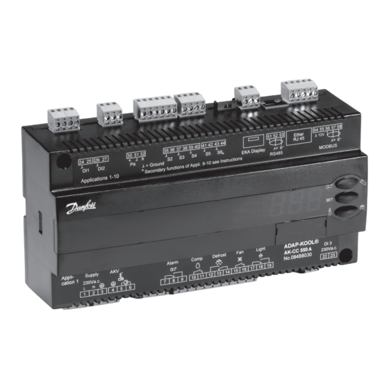
AK-CC 550A — 084B8070
Контроллер Danfoss AK-CC 550 может применяться для управления торговым холодильным оборудованием и холодильными камерами всех типов. Преимуществами данного контроллера являются: быстрая настройка с использованием предварительно заданных параметров, встроенная плата передачи данных, встроенные часы с автономным питанием.
Документация
Температура охлаждаемого воздуха измеряется одним или двумя датчиками температуры, установленными в воздушном потоке перед испарителем (S3) или после него (S4). Показания датчиков определяют работу управляющего и аварийного термостатов и дисплея. Для регистрации температуры продукта можно установить дополнительный датчик S6. В качестве датчика оттаивания можно использовать датчик температуры испарителя S5. Кроме выхода на электронный расширительный клапан типа AKV, контроллер имеет 5 релейных выходов, функции которых определяются выбранным режимом работы.
Функции:
— Термостат дневного и ночного режимов с двухпозиционным (ВКЛ/ОТКЛ.) или плавным регулированием(модулирующий термостат).
— Аварийный датчик температуры продуктов S6 с индивидуальными пределами сигнализации.
— Переключение между диапазонами термостата через цифровой вход.
— Адаптивный контроль перегрева.
— Адаптивное оттаивание по обмерзанию испарителя.
— Начало оттаивания по графику, сигналу цифрового входа или по сети передачи данных.
— Естественное оттаивание, оттаивание с помощью электронагревателя или горячего газа.
— Конец оттаивания по времени или температуре.
— Координированное оттаивание нескольких контроллеров (master—slave).
— Включение вентиляторов по сигналам термостата.
— Функция уборки для документального подтверждения выполнения требований НАССР.
— Контроль кантового подогрева стекол по дневномуночному режиму или по точке росы.
— Аварийная сигнализация двери.
— Управление двумя компрессорами.
— Управление ночными шторками.
— Управление освещением.
— Функция подогрева.
— Заводская настройка, обеспечивающая повышенную точность измерения температуры по сравнению требованиями, приведенными в стандарте EN 441‑13 (с датчиком температуры Pt 1000 Ом).
— Встроенная плата передачи данных MODBUS с возможностью подключения сетевой карты LonWorks или Ethernet.
| Электропитание | 230 В пер. тока, +10/−15%, 5 ВА | |
| Датчик S2 | Pt 1000 | |
| Датчики S3, S4, S5, S6 | Pt 1000 или РТС 1000 Ом / 25 °С (Все датчики должны быть одного типа) | |
| Погрешность | Диапазон измерения | От —60 до +120 °С |
| Контроллер | ±1 К при темп. ниже −35 °С ±0,5 К при темп. от −35 до +25°С ±1 К при темп. выше +25 °С |
|
| Датчик Pt 1000 | ±0,3 К при темп. 0 °С ±0,005 К на град. |
|
| Измерение давления | Датчик давления | AKS 32R |
| Дисплей контроллера | Светодиодный, 3‑разрядный | |
| Внешний дисплей | ЕКА 163В или 164В (любой ЕКА 163А или 164А) | |
| Цифровые входы DI1, DI2 | Сигнал от контактных функций. Рекомендуется использовать позолоченные контакты. Длина кабелей не более 15 м. При большей длине кабелей используйте дополнительные реле | |
| Цифровой вход DI3 | 230 В пер. тока | |
| Соединительные кабели | Многожильные кабели сечением не более 1,5 мм2 | |
| Твердотельное реле | DO1 (для катушки AKV) | Макс. 240 В пер. тока, мин. 28 В пер. тока Макс. 0,5 А Утечки тока < 1 мА Макс. кол‑во AKV: 1 |
| Реле | СЕ (250 В пер. тока | |
| DO3, DO4 | 4 (3) А | |
| DO2, DO5, DO6 | 4 (3) А | |
| Параметры окружающей среды | Температура окр. воздуха при эксплуатации: от 0 до +55 °С. Температура окр. воздуха при транспортировке: от −40 до +70 °С | |
| Отн. влажность воздуха: от 20 до 80%, не допускать конденсации | ||
| Не подвергать ударам и вибрации | ||
| Степень защиты корпуса | IP 20 | |
| Монтаж | На рейке DIN или на стене | |
| Масса | 0,4 кг | |
| Передача данных | Встроенный блок | MODBUS |
| Сетевые карты | LON RS485 | |
| TCP/IP | ||
| MODBUS | ||
| Контроллер не может работать с блоком мониторинга типа m2 | ||
| Время работы часов с источником питания | 4 часа | |
| Соответствие документам | Соответствует требованиям работы с низковольтным оборудованием и требованиям на электромагнитную совместимость. Проверен на соответствие стандартам EN 60730‑1, EN 60730‑2‑9, A1, A2, EN50082‑1 и EN 60730‑2‑9, A2 |