Преимущества серии
- простотой в обслуживании и вводе в эксплуатацию;
- малыми габаритами и массой с возможностью монтажа на DIN-рейку;
- возможностью плотной установки ПЧ и объединения их шин постоянного тока;
- наличием встроенного RS-485 порта и дополнительных;
- коммуникационных адаптеров для сетей Profibus, DeviceNet, LonWorks и CANopen;
- встроенным радиочастотным фильтром класса В (для моделей 1ф/230В и 3ф/400В).
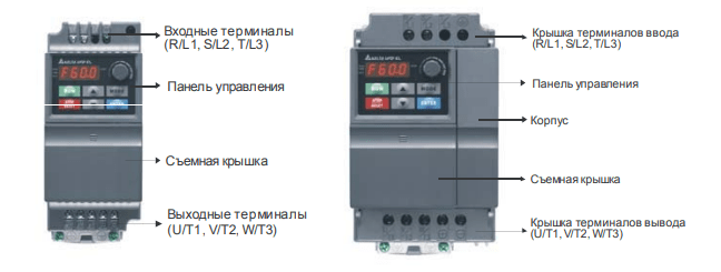
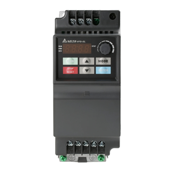
Внешний вид
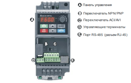
Внешний вид со снятой крышкой
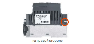
Местоположение RFI-переключателя
RFI-переключатель
Эксплуатация в сети с изолированной нейтралью:
Если ПЧ используется с незаземленным источником питания (IT), необходимо снять
внутренний фильтр радиопомех с помощью RFI-переключателя, который представляет собой
перемычку, которую необходимо удалить с помощью кусачиков или паяльника. RFIпереключатель отключает емкости фильтра от «земли» для предотвращения повреждения
схемы (согласно с IEC 61800-3) и снижает токи утечки на «землю». Расположение RFIпереключателя показано на вышеприведенном рисунке.
Основные правила подключения.
- Напряжение питания ПЧ должно подаваться только на клеммы R/L1, S/L2, T/L3. Чередование фаз соблюдать необязательно. Для предотвращения повреждений прикладывайте к клеммам преобразователя только напряжение, указанное на паспортной табличке ПЧ.
- Используйте кабель достаточного сечения. Падение напряжения в кабеле должно быть не более 2 %. При значительной длине проводов возможно снижение момента электродвигателя, особенно на низких частотах.
- Затягивайте клеммы с рекомендуемым моментом. Неплотная затяжка может быть причиной неправильной работы и обгорания клеммы.
- Слишком сильная затяжка может повредить клеммник.
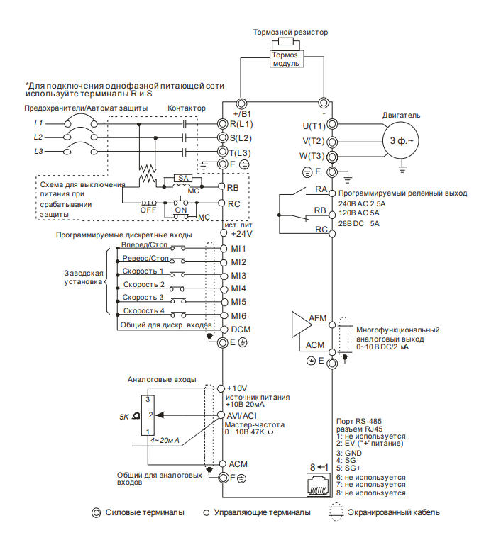
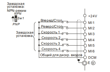
Базовая схема соединений
Данная схема не являются готовой для практического использования, а лишь показывает назначение и возможные соединения терминалов, выходные цепи ПЧ.
На схеме показано подключение трехфазной сети (Uном = 220 или 380В в зависимости от
типономинала). Для преобразователей с однофазным питанием 1ф/220В провода «фаза» и
«ноль» подключаются к терминалам R и S.
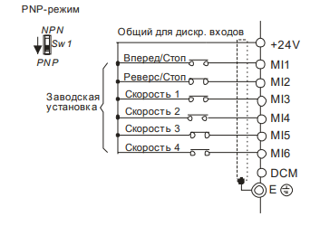
Выбор логики управления дискретными входами микропереключателем Sw1.
Монтаж силовых терминалов
| Обозначение | Описание |
| R/L1, S/L2, T/L3 | Клеммы для подключения питающей сети (ПЧ с однофазным питанием 220В подсоединяются к клеммам R и S) |
| U/T1, V/T2, W/T3 | Подключение трехфазного асинхронного двигателя |
| +, — | Подключение внешнего тормозного модуля серии BUE (опция) |
| Подключение заземляющего провода. Выполняйте защитное заземление в соответствие с требованиями ПУЭ |
Органы управления и индикация
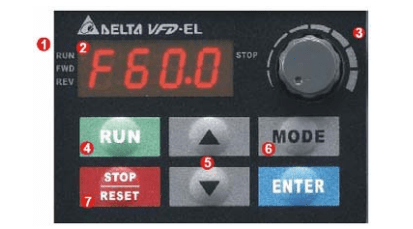
1) Дисплей состояния. Индикация состояния привода
2) LED-дисплей. Индикация частоты, тока, напряжения, параметров, кодов ошибок
3) Потенциометр. Задание частоты, если Pr.02.00 = 4
4) Кнопка RUN. Пуск привода
5) Кнопки UP и DOWN. Выбор параметра, изменение его значения, регулировка частоты
6) Кнопка MODE. Переключение между режимами индикации на LED-дисплее
7) Кнопка STOP/RESET. Останов привода и сброс аварийной блокировки. Кнопка ENTER. Ввод параметра
На панели управления имеется 4 светодиодных индикатора:
STOP: светится при остановленном приводе.
RUN: светится при действии команды RUN.
FWD: светится при прямом вращении.
REV: светится при реверсе.
Таблица основных программируемых параметров
Полный список параметров доступен в файле в конце страницы.
| Параметр | Описание | Диапазон установки, примечания | Завод. знач. |
|---|---|---|---|
| 00.03 | Выбор параметра отображаемого на дисплее при подаче питания | 0: Индикация заданной частоты (Fxxx) 1: Индикация фактической выходной частоты (Hxxx) 2: Индикация величины в единицах пользователя (Uxxx), где U=HxK 3: Многофункциональный дисплей, см. Pr.00.04 4: Команда FWD/REV (вперед/реверс) |
0 |
| 00.04 | Содержимое многофункционального дисплея | 0: Индикация величины в единицах пользователя (Uxxx), где U=HxK 1: Индикация значения счетчика (c) 2: Индикация состояния дискретных входов (d) 3: Индикация напряжения в звене постоянного тока (u) 4: Индикация выходного напряжения (E) 5: Индикация сигнала обратной связи ПИД-регулятора (b) (%) 6: Коэффициент мощности (n) 7: Индикация выходной мощности (P) 8: Индикация уставки и сигнала обратной связи ПИД-регулятора 9: Сигнал на входе AVI (I) (В) 10: Сигнал на входе ACI / AVI2 (i) (мА) 11: Температура IGBT-модуля (h) (C) |
0 |
| 00.05 | Пользовательский коэффициент K | 1 — 160.0 | 1.0 |
| 01.00 | Максимальная выходная частота (Fmax) | 50.00 — 600.0 Гц | 60.00 |
| 01.05 | Минимальная выходная частота (Fmin) | 0.10 — 600.0 Гц | 1.50 |
| 01.09 | Время разгона 1 | 0.1 — 600.0 / 0.01 — 600.0 сек | 10.0 |
| 01.10 | Время замедления 1 | 0.1 — 600.0 / 0.01 — 600.0 сек | 10.0 |
| 01.11 | Время разгона 2 | 0.1 — 600.0 / 0.01 — 600.0 сек | 10.0 |
| 01.12 | Время замедления 2 | 0.1 — 600.0 / 0.01 — 600.0 сек | 10.0 |
| 01.13 | Время разгона JOG | 0.1 — 600.0 / 0.01 — 600.0 сек | 10.0 |
| 01.14 | Время замедления JOG | 0.1 — 600.0 / 0.01 — 600.0 сек | 10.0 |
| 01.15 | Частота JOG | 0.10 Гц — Fmax (Pr.01.00) Гц | 6.00 |
| 02.00 | Первый источник задания выходной частоты |
0: Пульт (кнопки: ▲ и ▼) или внешние терминалы (кнопки: UP и DOWN) 1: Сигнал (0 … +10)В на входе AVI 2: Сигнал (4 … 20)мА на входе ACI 3: Интерфейс RS-485 (RJ-45). 4: Потенциометр пульта |
1 |
| 02.01 | Первый источник команд управления приводом | 0: Пульт (кнопки RUN, STOP) 1: Управление с внешних терминалов. Кнопка STOP/RESET на пульте активна. 2: Управление с внешних терминалов. Кнопка STOP/RESET на пульте не активна. 3: Интерфейс RS-485 (RJ-45). Кнопка STOP/RESET на пульте активна. 4: Интерфейс RS-485 (RJ-45). Кнопка STOP/RESET на пульте не активна. |
1 |
| 02.11 | Частота, заданная с пульта | 0.00 — 600.0 Гц | 60.00 |
| 02.12 | Частота, заданная по RS-485 | 0.00 — 600.0 Гц | 60.00 |
| 03.03 | Параметр, измеряемый на аналоговом выходе | 0: Выходная частота 1: Выходной ток |
0 |
| 03.04 | Коэф. усиления для аналогового выхода | 1 — 200% | 100 |
| 04.00 | Смещение сигнала потенциометра пульта | 0.0 — 100.0 % | 0.0 |
| 04.01 | Направление смещения сигнала потенциометра пульта |
0: Положительное смещение 1: Отрицательное смещение |
00 |
| 04.02 | Усиление сигнала потенциометра пульта |
0.1 — 200.0 % | 100.0 |
| 04.27 | Назначение дискретных входов для внешнего / внутреннего управления |
0~4095 | 0 |
| 04.28 | Внутреннее управление состоянием дискретных входов |
0~4095 | 0 |
| 05.00 — 05.14 | Фиксированная частота 1 — 14 |
0.00 — 600.0 Гц | 0.00 |
| 06.04 | Уровень обнаружения перегрузки OL2 | 10 — 200% | 150 |
| 07.00 | Номинальный ток двигателя | от 30 %FLA до 120% FLA, где FLA – номинальный выходной ток ПЧ |
FLA |
| 07.01 | Ток холостого хода двигателя | от 0%FLA до 99% FLA | 0.4хFLA |
| 07.02 | Компенсация момента | 0.0 — 10.0 | 0.0 |
| 07.03 | Компенсация скольжения | 0.00 — 10.00 | 0.00 |
| 08.20 | Компенсация неустойчивости вращения двигателя | 0.0~5.0 | 0.0 |
| 10.11 | Фиксированная уставка сигнала задания для ПИД регулятора |
0.00 — 600.0 Гц | 0.00 |
Основные проблемы и способы их устранения.
| Код | Описание аварии | Рекомендации по устранению |
| oc | Перегрузка по току. Выходной ток (мгновенное значение) преобразователя превысил допустимое значение. |
Проверьте, соответствует ли мощность двигателя мощности ПЧ, или лучше, — ток двигателя току преобразователя в пусковом и установившемся режимах. Проверьте кабельные соединения U/T1, V/T2, W/T3 преобразователя и двигателя на отсутствие короткого замыкания. Проверьте сопротивления обмоток двигателя на отсутствие межвитковых замыканий и замыканий землю. Проверьте надежность контактов между преобразователем и двигателем. Увеличьте время разгона (Pr.01.09, 01.11). Проверить, не перегружается ли двигатель. Если авария появляется после устранения короткого замыкания на выходе и выполнения других предыдущих пунктов или даже при отключенном двигателе, то обратитесь к поставщику |
| ou | Перегрузка по напряжению. Напряжение в звене постоянного тока преобразователя превысило допустимое значение. |
Проверьте напряжение сети, – не превышает ли оно допустимое значение. Проверьте диапазон колебания сетевого питания. Убедитесь в отсутствии выбросов напряжения сети. Перенапряжение в звене постоянного тока может также появиться в результате регенеративного торможения двигателя. Надлежит увеличить время торможения (Pr.01.10, 01.12), либо применить дополнительный модуль и резистор в цепи торможения или выбрать метод торможения на свободном выбеге (Pr.02.02). Проверьте, умещается ли требуемая мощность торможения в установленном диапазоне. |
| oX1 | Тепловая перегрузка. Датчик температуры радиатора зафиксировал превышение допустимой температуры. |
Проверьте, не превышает ли температура окружающей среды (непосредственно вокруг ПЧ) требуемых условий работы преобразователя. Убедитесь в том, что вентиляционные отверстия не загрязнены. Проверьте состояние рёбер радиатора и в случае необходимости очистите от наличия посторонних тел. Проверьте работу вентилятора и в случае необходимости очистите его от грязи. Обеспечьте требуемое охлаждающее пространство вокруг преобразователя. |
| Lu | Низкое напряжение. Напряжение в звене постоянного тока ниже допустимого уровня. |
Проверьте напряжение сети, – не ниже ли оно допустимого значения. Проверьте, не произошло ли на двигателе внезапное увеличение нагрузки. Проверьте правильность подключения клемм R-S-T (для 3-х фазных моделей), — все ли три фазы подключены. |
| oL | Перегрузка. Перегрузка инвертора по току. Примечание. ПЧ может выдержать 150% I ном максимум в течение 60сек. |
Проверьте нагрузку двигателя. Уменьшите уровень компенсации момента (Pr.07.02) Проверьте правильность установки характеристики V/f в параметрах 01.00, 01.01, 01.02, 01.03, 01.04, 01.05, 01.06 Выберите преобразователь с более высоким номиналом выходного тока. |
| oL1 | Перегрузка 1. Блокировка, связанная с действием внутренней электронной тепловой защиты двигателя. |
Проверьте нагрузку двигателя. Проверьте параметры электронного теплового реле (Pr.06.06, 06.07) Используйте двигатель большей мощности. Скорректируйте значение параметра Pr.07.00. |
| oL2 | Перегрузка 2 Перегрузка (превышение момента) двигателя. |
Уменьшите нагрузку двигателя. Скорректируйте режим обнаружения перегрузки в соответствующих параметрах (Pr.06.03 — Pr.06.05). |
| HPF1-4 | Аппаратная защита. | Обратитесь к поставщику |
| bb | Внешняя блокировка (пауза в работе). (См. Pr. 08.07) |
Когда на дискретном входе активна команда паузы (B.B), напряжение с силовых выходов инвертора будет снято. Снимите команду паузы с внешнего терминала для возобновления работы привода. |
| ocA | 2-х кратное превышение номинального тока ПЧ во время разгона. |
Короткое замыкание: проверьте кабель и изоляцию двигателя. Высокое начальное выходное напряжение: уменьшите компенсацию момента в Pr.07.02 или проверьте правильность характеристики V/f (параметры группы 2). Быстрый разгон: увеличьте время разгона (Pr.01.09, 01.11). Не хватает мощности для разгона: выберите модель ПЧ большей мощности. |
| ocd | 2-х кратное превышение номинального тока ПЧ во время замедления |
Короткое замыкание: проверьте кабель и изоляцию двигателя. Быстрое торможение: увеличьте время замедления (Pr.01.10, 01.12) или выберите метод торможения на свободном выбеге (Pr.02.02). Не хватает мощности для торможения: выберите модель ПЧ большей мощности. |
| ocn | 2-х кратное превышение номинального тока ПЧ на установившейся скорости. |
Короткое замыкание: проверьте кабель и изоляцию двигателя. Резкое увеличение нагрузки двигателя: проверьте, не остановился ли двигатель. Не хватает мощности для работы в данном режиме: выберите модель ПЧ большей мощности. |
| EF | Внешнее аварийное отключение |
Когда на дискретном входе (MI3-MI9) активна команда внешнего аварийного отключения привода, выходы U, V и W будут заблокированы. Для сброса блокировки надо снять команду внешней аварии и деблокировать привод командой RESET. |
| cF1.0-2.1 | Внутренняя EEPROM | Обратитесь к поставщику |
| cF3.0-3.2 | Ошибка в фазе | Обратитесь к поставщику |
| OFF | Короткое замыкание на землю. |
Если выходная фаза ПЧ замыкается на землю, и ток короткого замыкания на 50% превысил номинальное значение, может быть поврежден силовой модуль. Примечание: Схема защиты от короткого замыкания обеспечивает защиту привода, но не защищает персонал. Проверьте работоспособность силового модуля IGBT. Проверьте состояние изоляции выходных каналов привода. |
| cFA | Сбой при автоматическом разгоне/замедлении. |
Проверьте, подходит ли двигатель для работы с преобразователем частоты. Возможно слишком большая регенеративная энергия двигателя. Возможно внезапно изменилась нагрузка двигателя. |
| cE— | Ошибка коммуникации. | Проверьте правильность и надежность соединения по RS485 между преобразователем и ведущим устройством в сети. Проверьте протокол коммуникации, адрес, скорость передачи, и др. параметры коммуникации. Проверьте правильность расчета контрольной суммы. См. параметры группы 9 для подробной информации. |
| codE | Защита паролем. | Обратитесь к поставщику. |
| AErr | Отклонение аналогового сигнала. |
Проверьте соединение аналогового входа ACI |
| FbE | Ошибка ПИД-регулятора | Проверьте установку параметра (Pr.10.01) и соединения на входе AVI/ACI. Проверьте на предмет несоответствия между временем отклика системы и временем детектирования сигнала обратной связи (Pr.10.08) |
| PHL | Отсутствие фазы питающего напряжения. |
Проверьте наличие и симметрию всех трех фаз напряжения питания на входных клеммах (L1, L2, L3) преобразователя. |
Информацию о программируемых функциональных группах вы можете взять в файле ниже.
Скачать руководство по эксплуатации.

1
Руководство по эксплуатации
ПРЕОБРАЗОВАТЕЛИ ЧАСТОТЫ
серии VFD-EL
(220 В 0.2 – 2.2 кВт)
и
(380 В 0.4 – 3.7 кВт)
Руководство по эксплуатации
октябрь 2012г., 2ELE
-
Contents
-
Table of Contents
-
Troubleshooting
-
Bookmarks
Quick Links
20
+31 (0)40-803800/ FAX:+31(0)40-8003998
Sensorless Vector Control
Micro Drive
VFD-EL
5011662906
2016-03
6
E
L
E
www.delta.com.tw/ia
Series
User Manual
Related Manuals for Delta Electronics VFD-EL series
Summary of Contents for Delta Electronics VFD-EL series
-
Page 1
Sensorless Vector Control Micro Drive VFD-EL Series User Manual 5011662906 +31 (0)40-803800/ FAX:+31(0)40-8003998 2016-03 www.delta.com.tw/ia… -
Page 2
Ground the VFD-EL using the ground terminal. The grounding method must comply with the laws of the country where the AC motor drive is to be installed. Refer to the Basic Wiring Diagram. VFD-EL series is used only to control variable speed of 3-phase induction motors, NOT for 1-phase motors or other purpose. -
Page 3: Table Of Contents
Table of Contents Preface ……………………… i Table of Contents ………………….ii Chapter 1 Introduction ………………..1-1 1.1 Receiving and Inspection …………….. 1-1 1.1.1 Nameplate Information…………….1-1 1.1.2 Model Explanation ………………. 1-1 1.1.3 Series Number Explanation …………..1-2 1.1.4 Drive Frames and Appearances ………….. 1-2 1.1.5 Remove Instructions …………….
-
Page 4: Table Of Contents
5.10 Motor Speed cannot be Changed …………..5-7 5.11 Motor Stalls during Acceleration …………..5-8 5.12 The Motor does not Run as Expected …………5-8 5.13 Electromagnetic/Induction Noise …………..5-9 5.14 Environmental Condition …………….5-9 5.15 Affecting Other Machines …………….5-9 Chapter 6 Fault Code Information and Maintenance ……….
-
Page 5: Table Of Contents
B.8.3.5 PROFIBUS Address …………..B-17 B.8.4 CME-COP01 (CANopen) …………… B-18 B.8.4.1 Product Profile …………….B-18 B.8.4.2 Specifications …………….B-18 B.8.4.3 Components ……………… B-19 B.8.4.4 LED Indicator Explanation & Troubleshooting ……. B-20 B.9 MKE-EP & DIN Rail ………………B-21 B.9.1 MKE-EP ………………..B-21 B.9.2 DIN Rail: MKEL-DRA (Only for frame A) ……….
-
Page 6
This page intentionally left blank… -
Page 8: Chapter 1 Introduction
230V 1- phase 23:230 V 3- phase 43:460 V 3- phase VFD-EL Series Applicable motor capacity 015: 2 HP(1.5kW) 002: 0.25 HP(0.2kW) 004: 0.5 HP(0.4kW) 022: 3 HP(2.2kW) 037: 5 HP(3.7kW) Series Name ( ariable requency rive) Revision 2016/03, 6ELE, V1.14…
-
Page 9: Series Number Explanation
Chapter 1 Introduction| | | | 1.1.3 Series Number Explanation 1230 007EL23A Production number Production week Production year 2007 Production factory T: Taoyuan, W: Wujiang 230V 3-phase 1HP(0.75kW) Model If the nameplate information does not correspond to your purchase order or if there are any problems, please contact your distributor.
-
Page 10: Remove Instructions
Chapter 1 Introduction | | | | Frame Power range Models VFD002EL11A/21A/23A, VFD004EL11A/21A/23A/43A, 0.25-2hp (0.2-1.5kW) VFD007EL21A/23A/43A, VFD015EL23A/43ª VFD007EL11A, VFD015EL21A, VFD022EL21A/23A/43A, 1-5hp (0.75-3.7kW) VFD037EL23A/43A RFI Jumper RFI Jumper: The AC motor drive may emit the electrical noise. The RFI jumper is used to suppress the interference (Radio Frequency Interference) on the power line.
-
Page 11: Preparation For Installation And Wiring
Chapter 1 Introduction| | | | 1.2 Preparation for Installation and Wiring 1.2.1 Ambient Conditions Install the AC motor drive in an environment with the following conditions: -10 ~ +50° C (14 ~ 122° F) for UL & cUL Air Temperature: -10 ~ +40°…
-
Page 12: Dc-Bus Sharing: Connecting The Dc-Bus Of The Ac Motor Drives In
Chapter 1 Introduction | | | | 120mm 150mm 120mm 150mm 120mm 150mm 120mm 150mm Air flow 120mm 150mm 120mm 150mm Frame A Frame A Frame B Frame B 1.2.2 DC-bus Sharing: Connecting the DC-bus of the AC Motor Drives in Parallel 1.
-
Page 13: Dimensions
Chapter 1 Introduction| | | | 1.3 Dimensions (Dimensions are in millimeter and [inch]) H H1 Frame Ø ØD 72.0[2.83] 59.0[2.32] 174.0[6.86] 151.6[5.97] 136.0[5.36] 5.4[0.21] 2.7[0.11] 100.0[3.94] 89.0[3.50] 174.0[6.86] 162.9[6.42] 136.0[5.36] 5.4[0.21] 2.7[0.11] NOTE Frame A: VFD002EL11A/21A/23A, VFD004EL11A/21A/23A/43A, VFD007EL21A/23A/43A, VFD015EL23A/43A Frame B: VFD007EL11A, VFD015EL21A, VFD022EL21A/23A/43A, VFD037EL23A/43A Revision 2016/03, 6ELE, V1.14…
-
Page 14: Chapter 2 Installation And Wiring
AC motor drive and the motor nameplate for electrical data. The «Line Fuse Specification» in Appendix B, lists the recommended fuse part number for each VFD-EL Series part number. These fuses (or equivalent) must be used on all installations where compliance with U.L.
-
Page 15: Wiring
RS-485 communication port or permanent damage may result. The pins 1 & 2 are the power supply for the optional copy keypad only and should not be used for RS-485 communication. Figure 1 for models of VFD-EL Series VFD002EL11A/21A, VFD004EL11A/21A, VFD007EL11A/21A, VFD015EL21A, VFD022EL21A…
-
Page 16
Revision 2016/03, 6ELE, V1.14… -
Page 17
Chapter 2 Installation and Wiring| | | | Figure 3 Wiring for NPN mode and PNP mode A. NPN mode without external power Factory setting B. NPN mode with external power Factory setting C. PNP mode without external power Factory setting D. -
Page 18
Use ground leads that comply with local regulations and keep them as short as possible. No brake resistor is built in the VFD-EL series, it can install brake resistor for those occasions that use higher load inertia or frequent start/stop. Refer to Appendix B for details. -
Page 19: External Wiring
Chapter 2 Installation and Wiring| | | | 2.2 External Wiring Items Explanations P o w e r S u p p l y Please follow the specific power supply Power supply requirements shown in Appendix A. There may be an inrush current during power up.
-
Page 20: Main Circuit
Use well-insulated motor, suitable for inverter operation. Terminals [+, -] for connecting brake resistor All VFD-EL series don’t have a built-in brake chopper. Please connect an external optional brake unit (BUE- series) and brake resistor. Refer to BUE series user manual for details.
-
Page 21: Main Circuit Terminals
Chapter 2 Installation and Wiring| | | | 2.3.2 Main Circuit Terminals Frame A Frame B Frame Power Terminals Torque Wire Wire type R/L1, S/L2, T/L3 14.2-16.3kgf-cm 12-18 AWG. Copper only, 75 (3.3-0.8mm (12-14in-lbf) U/T1, V/T2, W/T3, R/L1, S/L2, T/L3 16.3-19.3kgf-cm 8-18 AWG.
-
Page 22: Control Terminals
2.4 Control Terminals Circuit diagram for digital inputs (NPN current 16mA.) NPN Mode PNP Mode +24V +24V The position of the control terminals MI1 MI3 MI5 RS-485 MI2 MI4 MI6 DCM RA RB RC Terminal symbols and functions Terminal Symbol Terminal Function Factory Settings (NPN mode) ON: Connect to DCM Run in MI1 direction…
-
Page 23
Chapter 2 Installation and Wiring| | | | Terminal Symbol Terminal Function Factory Settings (NPN mode) ON: Connect to DCM Analog voltage Input +10V Impedance: 47k AVI circuit Resolution: 10 bits Range: 0 ~ 10VDC/4~20mA = 0 ~ Max. Output Frequency (Pr.01.00) Selection: Pr.02.00, Pr.02.09, Pr.10.00 Set-up: Pr.04.14 ~ Pr.04.17… -
Page 24
The specification for the control terminals The position of the control terminals MI1 MI3 MI5 RS-485 MI2 MI4 MI6 DCM RA RB RC Frame Torque Wire A, B 5.1-8.1kgf-cm (4.4-7in-lbf) 16-24 AWG. (1.3-0.2mm NOTE Frame A: VFD002EL11A/21A/23A, VFD004EL11A/21A/23A/43A, VFD007EL21A/23A/43A, VFD015EL23A/43A Frame B: VFD007EL11A, VFD015EL21A, VFD022EL21A/23A/43A, VFD037EL23A/43A 2-11 Revision 2016/03, 6ELE, V1.14… -
Page 26: Chapter 3 Keypad And Start Up
Chapter 3 Keypad and Start Up 3.1 Description of the Digital Keypad There are four LEDs on the keypad: LED STOP: It will light up when the motor is stop. LED RUN: It will light up when the motor is running. LED FWD: It will light up when the motor is forward running.
-
Page 27: How To Operate The Digital Keypad
Chapter 3 Keypad and Start Up| | | | 3.2 How to Operate the Digital Keypad Setting Mode S TART MODE MO DE MO DE MO DE MO DE GO START NOTE: In the selection mode, press to set the parameters. MODE Setting parameters Input data error…
-
Page 28: Operation Method
3.4 Operation Method The operation method can be set via communication, control terminals and digital keypad. Operation Method Frequency Source Operation Command Source When setting communication by the PC, it needs to use VFD-USB01 or IFD8500 Operate from the converter to connect to the PC. communication Refer to the communication address 2000H and 2101H setting for details.
-
Page 29: Trial Run
Chapter 3 Keypad and Start Up| | | | 3.5 Trial Run You can perform a trial run by using digital keypad with the following steps. by following steps Setting frequency to F5.0 by pressing If you want to change direction from forward running to reverse running: 1. press key to find FWD.
-
Page 30: Chapter 4 Parameters
Chapter 4 Parameters The VFD-EL parameters are divided into 11 groups by property for easy setting. In most applications, the user can finish all parameter settings before start-up without the need for re-adjustment during operation. The 11 groups are as follows: Group 0: User Parameters Group 1:…
-
Page 31: Summary Of Parameter Settings
Chapter 4 Parameters| | | | 4.1 Summary of Parameter Settings : The parameter can be set during operation. Group 0 User Parameters Factory Parameter Function Setting Customer Setting 00.00 Identity Code of the AC motor Read-only drive 00.01 Rated Current Display of the Read-only AC motor drive 0: Parameter can be read/written…
-
Page 32
Factory Parameter Function Setting Customer Setting 0: 230V/400V 00.12 50Hz Base Voltage Selection 1: 220V/380V User-defined Value 0 to 9999 00.13 (correspond to max. operating frequency) Decimal place of User-defined 0 to 3 00.14 Value Revision 2016/03, 6ELE, V1.14… -
Page 33
Chapter 4 Parameters| | | | Group 1 Basic Parameters Factory Parameter Function Setting Customer Setting 01.00 Maximum Output Frequency (Fmax) 50.00 to 599.0 60.00 01.01 Maximum Voltage Frequency (Fbase) 0.10 to 599.0 60.00 115V/230V series: 0.1V to 255.0V 220.0 01.02 Maximum Output Voltage (Vmax) 460V series: 0.1V to 510.0V… -
Page 34
Factory Parameter Function Setting Customer Setting 01.30 Delay Time of Simple Positioning Stop 2 0.00 01.31 Delay Time of Simple Positioning Stop 3 0.00 0.00~600.00 sec 01.32 Delay Time of Simple Positioning Stop 4 0.00 01.33 Delay Time of Simple Positioning Stop 5 0.00 01.34 Delay Time of Simple Positioning Stop 6… -
Page 35
Chapter 4 Parameters| | | | Group 2 Operation Method Parameters Factory Parameter Function Setting Customer Setting 0: Digital keypad UP/DOWN keys or Multi- function Inputs UP/DOWN. Last used frequency saved. Source of First Master 02.00 1: 0 to +10V from AVI Frequency Command 2: 4 to 20mA from ACI 3: RS-485 (RJ-45) communication… -
Page 36
Factory Parameter Function Setting Customer Setting Accel/Decel Rate of Change of 02.08 UP/DOWN Operation with 0.01~10.00 Hz 0.01 Constant Speed 0: Digital keypad UP/DOWN keys or Multi- function Inputs UP/DOWN. Last used frequency saved. Source of Second Frequency 1: 0 to +10V from AVI 02.09 Command 2: 4 to 20mA from ACI… -
Page 37
Chapter 4 Parameters| | | | Group 3 Output Function Parameters Factory Custome Parameter Function Setting Setting 0: No function 1: AC drive operational 2: Master frequency attained 3: Zero speed 4: Over torque detection 5: Base-Block (B.B.) indication 6: Low-voltage indication 7: Operation mode indication Multi-function Output 03.00… -
Page 38
Factory Custome Parameter Function Setting Setting 03.09 Reserved 03.10 Reserved Brake Release 03.11 0.00 to 20.00Hz 0.00 Frequency Brake Engage 03.12 0.00 to 20.00Hz 0.00 Frequency Display the Status of 03.13 Read only Relay Revision 2016/03, 6ELE, V1.14… -
Page 39
Chapter 4 Parameters| | | | Group 4 Input Function Parameters Factory Custome Parameter Function Setting Setting 04.00 Keypad Potentiometer Bias 0.0 to 100.0 % 0: Positive bias 04.01 Keypad Potentiometer Bias Polarity 1: Negative bias 04.02 Keypad Potentiometer Gain 0.1 to 200.0 % 100.0 0: No negative bias command… -
Page 40
Factory Custome Parameter Function Setting Setting Bit0:MI1 Bit1:MI2 Bit2:MI3 Bit3:MI4 04.09 Multi-function Input Contact Selection Bit4:MI5 Bit5:MI6 0:N.O., 1:N.C. P.S.:MI1 to MI3 will be invalid when it is 3-wire control. 04.10 Digital Terminal Input Debouncing Time 1 to 20 (*2ms) Min AVI Voltage 0.00 to 10.00V 04.11… -
Page 41
Chapter 4 Parameters| | | | Group 5 Multi-Step Speed Parameters Parameter Function Setting Factory Setting Customer 05.00 1st Step Speed Frequency 0.00 to 599.0 0.00 05.01 2nd Step Speed Frequency 0.00 to 599.0 0.00 05.02 3rd Step Speed Frequency 0.00 to 599.0 0.00… -
Page 42
Group 6 Protection Parameters Factory Custome Parameter Function Setting Setting 115/230V series: 330.0V to 410.0V 390.0V Over-Voltage Stall 06.00 460V series: 660.0V to 820.0V 780.0V Prevention 0.0: Disable over-voltage stall prevention 0:Disable Over-Current Stall 06.01 Prevention during Accel 20 to 250% Over-Current Stall 0:Disable 06.02… -
Page 43
Chapter 4 Parameters| | | | Factory Custome Parameter Function Setting Setting 20: CC, OC Hardware protection failure (HPF1) 21: OV Hardware protection failure (HPF2) 22: GFF Hardware protection failure (HPF3) 23: OC Hardware protection failure (HPF4) 24: U-phase error (cF3.0) 25: V-phase error (cF3.1) 26: W-phase error (cF3.2) 27: DCBUS error (cF3.3) -
Page 44
Group 7 Motor Parameters Factory Custome Parameter Explanation Settings Setting 07.00 Motor Rated Current 30 %FLA to 120% FLA 07.01 Motor No-Load Current 0%FLA to 99% FLA 0.4*FLA 07.02 Torque Compensation 0.0 to 10.0 07.03 Slip Compensation Gain 0.00 to 10.00 0.00 07.04 Motor Parameters Auto Tuning… -
Page 45
Chapter 4 Parameters| | | | Group 8 Special Parameters Factory Custome Parameter Explanation Settings Setting 08.00 DC Brake Current Level 0 to 100% DC Brake Time during 08.01 0.0 to 60.0 sec Start-Up DC Brake Time during 08.02 0.0 to 60.0 sec Stopping 08.03 Start-Point for DC Brake… -
Page 46
Group 9 Communication Parameters Parameter Explanation Settings Factory Setting Customer 09.00 Communication Address 1 to 254 0: Baud rate 4800bps 1: Baud rate 9600bps 09.01 Transmission Speed 2: Baud rate 19200bps 3: Baud rate 38400bps 0: Warn and keep operating 1: Warn and ramp to stop 09.02 Transmission Fault Treatment… -
Page 47
Chapter 4 Parameters| | | | Group 10 PID Control Parameters Factory Custome Parameter Explanation Settings Setting 0: Disable PID operation 1: Keypad (based on Pr.02.00) 10.00 PID Set Point Selection 2: 0 to +10V from AVI 3: 4 to 20mA from ACI 4: PID set point (Pr.10.11) 0: Positive PID feedback from external terminal AVI (0 ~ +10VDC) -
Page 48
Factory Custome Parameter Explanation Settings Setting 0: Warning but continue to operate 1: Error and coast to stop 2: Error and ramp to stop Treatment of the Erroneous 3: Ramp to stop and restart after time set at 10.20 PID Feedback Level Pr10.21 (No display of error and warning) 4: Ramp to stop and restart after time set at Pr10.21. -
Page 49
Chapter 4 Parameters| | | | Factory Custome Parameter Explanation Settings Setting Bit0: whether to switch to an alternative pump when operation pump error occurred. 0: Stop all pump action 1: Switch to an alternative pump Bit1: Standby or stop after resetting from error. 10.43 Pump’s error handling 0: Standby after reset. -
Page 50: Parameter Settings For Applications
4.2 Parameter Settings for Applications Speed Search Related Applications Purpose Functions Parameters Windmill, winding Restart free- Before the free-running motor is completely stopped, it can be 08.04~08.08 machine, fan and all running restarted without detection of motor speed. The AC motor inertia loads motor drive will auto search motor speed and will accelerate when…
-
Page 51
Chapter 4 Parameters| | | | Overheat Warning Related Applications Purpose Functions Parameters 03.00 Safety When AC motor drive overheats, it uses a thermal sensor to have conditioner measure overheat warning. 04.05~04.08 Two-wire/three-wire Related Applications Purpose Functions Parameters 02.00 MI1:(«OPEN»:STOP) FWD/STOP 02.01 («CLOSE»:FWD) -
Page 52
Emergency Stop by DC Brake Related Applications Purpose Functions Parameters 08.00 Emergency stop AC motor drive can use DC brake for emergency stop when High-speed 08.02 without brake quick stop is needed without brake resistor. When used often, rotors resistor take motor cooling into consideration. -
Page 53
Chapter 4 Parameters| | | | Output Signal at Desired Frequency Related Applications Purpose Functions Parameters When the output frequency is at the desired frequency (by 03.00 General Provide a signal frequency command), a signal is given for external system or application for running status control wiring (frequency attained). -
Page 54: Description Of Parameter Settings
4.3 Description of Parameter Settings Group 0: User Parameters : This parameter can be set during operation. 00.00 Identity Code of the AC Motor Drive Settings Read Only Factory setting: ## 00.01 Rated Current Display of the AC Motor Drive Settings Read Only Factory setting: #.#…
-
Page 55
Chapter 4 Parameters| | | | 00.04 Content of Multi-function Display Factory Setting: 0 Settings Display the content of user-defined unit (Uxxx) Display the counter value which counts the number of pulses on TRG terminal Display status of multi-input terminals (d) Display the actual DC BUS voltage in VDC of the AC motor drive Display the output voltage in VAC of terminals U/T1, V/T2, W/T3 to the motor. -
Page 56
Password has been set To set a password to protect your parameter settings. If the display shows 0, no password is set or password has been correctly entered in Pr.00.08. All parameters can then be changed, including Pr.00.09. The first time you can set a password directly. After successful setting of password the display will show 1. Be sure to record the password for later use. -
Page 57
Chapter 4 Parameters| | | | 1. The mechanical characteristic curve of the motor will not be modified, but the mains frequency and mains voltage will be changed. This control mode allows the motor drive to do open loop running and also allow the motor drive to do closed loop running with a PG card (an optional accessory). -
Page 58
Group 1: Basic Parameters Maximum Output Frequency (Fmax) 01.00 Unit: 0.01 Settings 50.00 to 599.0 Factory Setting: 60.00 This parameter determines the AC motor drive’s Maximum Output Frequency. All the AC motor drive frequency command sources (analog inputs 0 to +10V and 4 to 20mA) are scaled to correspond to the output frequency range. -
Page 59
Chapter 4 Parameters| | | | Output Frequency Upper Limit value = (Pr.01.00 * Pr.01.07)/100. 01.08 01.07 Output Frequency Output Frequency Voltage Lower Limit Upper Limit 01.02 Maximum Output Voltage 01.04 Mid-point Voltage The limit of Output Frequency Frequency 01.06 Minimum 01.05 01.03… -
Page 60
Frequency 01.00 Max. output Frequency setting operation frequency 01.05 Min. output frequency 0 Hz Decel. Time Accel. Time Time 01.09 01.11 01.10 01.12 The definition of Accel./Decel. Time Resulting Resulting Decel. Time Accel. Time Resulting Accel./Decel. Time 01.13 Jog Acceleration Time Unit: 0.1/0.01 Settings 0.1 to 600.0/0.01 to 600.0 sec… -
Page 61
Chapter 4 Parameters| | | | 01.16 Auto-Acceleration / Deceleration Factory Setting: 0 Settings Linear acceleration / deceleration Auto acceleration, linear Deceleration. Linear acceleration, auto Deceleration. Auto acceleration / deceleration (set by load) Auto acceleration / deceleration (set by Accel/Decel Time setting) With Auto acceleration / deceleration it is possible to reduce vibration and shocks during starting/stopping the load. -
Page 62
Settings 0.00 ~599.00Hz Factory Setting: 5.00 01.22 Simple Positioning Stop Frequency 2 Unit: 0.01 Settings 0.00 ~599.00Hz Factory Setting: 10.00 01.23 Simple Positioning Stop Frequency 3 Unit: 0.01 Settings 0.00 ~599.00Hz Factory Setting: 20.00 01.24 Simple Positioning Stop Frequency 4 Unit: 0.01 Settings 0.00 ~599.00Hz… -
Page 63
Chapter 4 Parameters| | | | × × s: distance travelled(round) n: rotation speed (round/ minute) n: rotation speed(round/second) p: number of poles of motors f: rotation frequency (Hz) : delay time(second) : deceleration time (second) The value of in the equation above is as shown below. -
Page 64
Therefore the distance travelled by the motor after the stop command is given = number of rounds x circumference = 175x 2πr. That means the turbtable went back to the top after 175 rounds. Example 02 Suppose that turntable is rotating at 1.5Hz, the Pr01.22 =10Hz [Simple Positioning Stop Frequency 2], and Pr01.30 =10 sec [Delay Time of Simple Positioning Stop 2], then the deceleration time will be 40 sec for decreasing from 60Hz to 0Hz. -
Page 65
Chapter 4 Parameters| | | | Group 2: Operation Method Parameters 02.00 Source of First Master Frequency Command Factory Setting: 1 02.09 Source of Second Master Frequency Command Factory Setting: 0 Settings Digital keypad UP/DOWN keys or Multi-function Inputs UP/DOWN. Last used frequency saved. -
Page 66
The motor stop method is usually determined by the characteristics of the motor load and how frequently it is stopped. (1) It is recommended to use “ramp to stop” for safety of personnel or to prevent material from being wasted in applications where the motor has to stop after the drive is stopped. -
Page 67
Chapter 4 Parameters| | | | From the table, we see that the PWM carrier frequency has a significant influence on the electromagnetic noise, AC motor drive heat dissipation, and motor acoustic noise. The PWM carrier frequency will be decreased automatically by the ambient temperature and output current of the AC motor drives. -
Page 68
When the source of the command changes, VFD’s operation remains the same. When the source of the command changes, VFD’s operation follows the new command. The motor drive can start to run at power on or after reset. When the source of command is a 2-wire external terminal, the operating command changes as the external terminal’s status changes. -
Page 69
Chapter 4 Parameters| | | | The Line Start Lockout feature does not guarantee that the motor will never start under this condition. It is possible the motor may be set in motion by a malfunctioning switch. 02.06 Loss of ACI Signal (4-20mA) Factory Setting: 0 Settings Decelerate to 0Hz… -
Page 70
02.13 The Selections for Saving Keypad or Communication Frequency Command Factory Setting: 0 Settings Save Keypad & Communication Frequency Save Keypad Frequency only Save Communication Frequency only This parameter is used to save keypad or RS-485 frequency command. 02.14 Initial Frequency Selection (for keypad & RS485) Factory Setting: 0 Settings By Current Freq Command… -
Page 71
Chapter 4 Parameters| | | | For example: suppose that the frequency source is the first master frequency + second master frequency command (first master frequency is from keypad and second master frequency is from AVI), user-defined value 1 is set to 180.0(Pr.00.13 is set to 1800, Pr.00.14 is set to 1). AVI=2V=180.0/(2V/10V)=36.0, frequency is 36.0/(180.0/60.0)=12.0Hz Pr.02.18=30.0, frequency is 30.0/(60.0/180.0)=10.0Hz At this moment, the keypad will display 66.0(36.0+30.0) and the output frequency is 22.0Hz(12.0+10.0). -
Page 72
Group 3: Output Function Parameters 03.00 Multi-function Output Relay (RA1, RB1, RC1) Factory Setting: 8 Settings Function Description No Function AC Drive Operational Active when the drive is ready or RUN command is “ON”. Master Frequency Attained Active when the AC motor drive reaches the output frequency setting. -
Page 73
Chapter 4 Parameters| | | | MO 23 description: Hand Auto Switch Pressure Sensor Master Auto mode Indicator Hand mode Light STOP RS485 If any error occurred on the inverter of the multi-pump system, the RLY will be turned on Wiring of the pressure sensor: Connect pressure sensor to +10V and AVI, then switch the SW2 switch to ACI 03.01… -
Page 74
Frequency detection master range frequency detection range detection -2Hz range desired waiting time frequency DC braking time 03.02 during stop frequency Time run/stop master freq. attained (output signal) desired freq. attained setting 03 zero speed indication setting 19 zero speed indication output timing chart of multiple function terminals when setting to frequency attained or zero speed indication Analog Output Signal (AFM) -
Page 75
Chapter 4 Parameters| | | | 2msec Display (Pr.00.04=1) Counter Trigger 2msec The width of trigger signal Preliminary Count Value should not be less than (Pr. 03.00=11) 2ms(<250 Hz) Ex:03.05=5,03.06=3 Terminal Count Value (Pr. 03.00=10) 03.07 EF Active when Terminal Count Value Attained Factory Setting: 0 Settings Terminal count value attained, no EF display… -
Page 76
Frequency Output Case 1: Pr.03.12 Pr. 03.11 Case 2: Pr.03.12 Time Run/Stop Case 1: Pr.03.00=21 Case 2: Pr.03.00=21 03.13 Display the Status of Relay Settings Read Only Factory setting: ## For standard AC motor drive, the multi-function output terminals are falling-edge triggered. 0: Relay is ON;… -
Page 77
Chapter 4 Parameters| | | | Group 4: Input Function Parameters 04.00 Keypad Potentiometer Bias Unit: 0. 1 Settings 0.0 to 100.0% Factory Setting: 0.0 04.01 Keypad Potentiometer Bias Polarity Factory Setting: 0 Settings Positive Bias Negative Bias 04.02 Keypad Potentiometer Gain Unit: 0.1 Settings 0.1 to 200.0%… -
Page 78
Example 4: Use of 0-5V potentiometer range via gain adjustment This example shows a potentiometer range of 0 to 5 Volts. Instead of adjusting gain as example below, you can set Pr. 01.00 to 120Hz to achieve the same results. Gain adjustment Pr.01.00=60Hz—Max. -
Page 79
Chapter 4 Parameters| | | | Example 8: Use negative slope In this example, the use of negative slope is shown. Negative slopes are used in applications for control of pressure, temperature or flow. The sensor that is connected to the input generates a large signal (10V) at high pressure or flow. -
Page 80
01.00=60.00 Hz 04.14=70 04.18=50 04.12=30 analog input 04.16=0 04.13=10V 04.11=0V 04.15=4mA 04.17=20mA 04.19 Reserved 04.20 Reserved 04.21 Reserved 04.22 Reserved 04.23 Reserved 04.24 Reserved 04.25 Reserved Multi-function Input Terminal (MI1, MI2) 2-wire/ 3-wire Operation Control Modes 04.04 Factory Setting: 0 Settings 2-wire: FWD/STOP, REV/STOP 2-wire: FWD/REV, RUN/STOP… -
Page 81
Chapter 4 Parameters| | | | 04.06 Multi-function Input Terminal (MI4) Factory Setting: 2 04.07 Multi-function Input Terminal (MI5) Factory Setting: 3 04.08 Multi-function Input Terminal (MI6) Factory Setting: 4 Settings Function Description Any unused terminals should be programmed to 0 to insure they No Function have no effect on operation. -
Page 82
Settings Function Description When an input ON with this setting is ON, the PID function will be PID function disabled disabled. AC motor drive will stop output and the motor free run if one of these Output Shutoff Stop settings is enabled. If the status of terminal is changed, AC motor drive will restart from 0Hz. -
Page 83
Chapter 4 Parameters| | | | Wiring of the pressure sensor: Connect pressure sensor to +10V and AVI, then switch the SW2 switch to ACI Hand & Auto mode: (1) If any error occurred to the pressure sensor, the operation can be switched to be hand mode. That means the operation is controlled by stand-alone system (RUN/STOP) (2) When under auto mode control, only the master pump cab perform operating control. -
Page 84
This parameter is to delay the signals on digital input terminals. 1 unit is 2 msec, 2 units are 4 msec, etc. The delay time is to debounce noisy signals that could cause the digital terminals to malfunction. 04.26 Display the Status of Multi-function Input Terminal Settings Read Only Factory setting: ##… -
Page 85
Chapter 4 Parameters| | | | 0=external terminal Weights 1=internal terminal Internal Terminal Status 04.28 Unit: 1 0 to 4095 Settings Factory Setting: 0 This parameter is used to set the internal terminal action via keypad or communication. For standard AC motor drive, the multi-function input terminals are MI1 to MI6 as shown in the following. 0=set internal terminal to be OFF Weights set internal terminal to be… -
Page 86
Group 5: Multi-step speeds parameters 05.00 1st Step Speed Frequency Unit: 0.01 05.01 2nd Step Speed Frequency Unit: 0.01 05.02 3rd Step Speed Frequency Unit: 0.01 05.03 4th Step Speed Frequency Unit: 0.01 05.04 5th Step Speed Frequency Unit: 0.01 05.05 6th Step Speed Frequency Unit: 0.01… -
Page 87
Chapter 4 Parameters| | | | MI6=4 MI5=3 MI4=2 MI3=1 Master frequency speed speed speed speed speed speed speed speed speed speed speed speed speed speed speed 4-58 Revision 2016/03, 6ELE, V1.14… -
Page 88
Group 6: Protection Parameters 06.00 Over-Voltage Stall Prevention Unit: 0.1 Settings 115V/230V series 330.0 to 410.0V Factory Setting: 390.0 460V series 660.0 to 820.0V Factory Setting: 780.0 Disable Over-voltage Stall Prevention (with brake unit or brake resistor) During deceleration, the DC bus voltage may exceed its Maximum Allowable Value due to motor regeneration. When this function is enabled, the AC motor drive will not decelerate further and keep the output frequency constant until the voltage drops below the preset value again. -
Page 89
Chapter 4 Parameters| | | | 06.01 output current Over-Current Detection Level setting frequency Over-Current Stall prevention during Output Acceleration, Frequency frequency held time previous acceleration time actual acceleration time when over-current stall prevention is enabled Over-current Stall Prevention during Operation 06.02 Unit: 1 Settings… -
Page 90
06.05 Over-Torque Detection Time (OL2) Unit: 0.1 Settings 0.1 to 60.0 sec Factory Setting: 0.1 This parameter sets the time for how long over-torque must be detected before “OL2” is displayed. 06.06 Electronic Thermal Overload Relay Selection (OL1) Factory Setting: 2 Settings Operate with a Standard Motor (self-cooled by fan) Operate with a Special Motor (forced external cooling) -
Page 91
Chapter 4 Parameters| | | | Current exceeds 2 times rated current during decel.(ocd) Current exceeds 2 times rated current during steady state operation (ocn) Ground fault (GFF) Reserved Phase-loss (PHL) Reserved Auto accel/decel failure (CFA) Software/password protection (codE) Power Board CPU WRITE Failure (cF1.0) Power Board CPU READ Failure (cF2.0) CC, OC Hardware protection failure (HPF1) OV Hardware protection failure (HPF2) -
Page 92
Group 7: Motor Parameters 07.00 Motor Rated Current Unit: 1 Settings 30% FLA to 120% FLA Factory Setting: FLA Use the following formula to calculate the percentage value entered in this parameter: (Motor Current / AC Drive Current) x 100% with Motor Current=Motor rated current in A on type shield AC Drive Current=Rated current of AC drive in A (see Pr.00.01) 07.01… -
Page 93
Chapter 4 Parameters| | | | 07.06 Motor Rated Slip (Motor 0) Unit: 0.01 Settings 0.00~20.00Hz Factory Setting: 3.00 To setup the rated slip of the motor. Refer to the rated rpm on the nameplate of the motor and use the following equation to determine the slip. ×… -
Page 94
If temperature exceeds the setting level, motor will be coast to stop and is displayed. When the temperature decreases below the level of (Pr.07.15-Pr.07.16) and stops blinking, you can press RESET key to clear the fault. Pr.07.14 (overheat protection level) must exceed Pr.07.15 (overheat warning level). The PTC uses the AVI-input and is connected via resistor-divider as shown below. -
Page 95
Chapter 4 Parameters| | | | If temperature exceeds the motor PTC overheat warning level (Pr.07.15), the drive will act according to Pr.07.17 and display . If the temperature decreases below the result (Pr.07.15 minus Pr.07.16), the warning display will disappear. 07.13 Input Debouncing Time of the PTC Protection Unit: 2ms… -
Page 96
Group 8: Special Parameters 08.00 DC Brake Current Level Unit: 1 Settings 0 to 100% Factory Setting: 0 This parameter sets the level of DC Brake Current output to the motor during start-up and stopping. When setting DC Brake Current, the Rated Current (Pr.00.01) is regarded as 100%. It is recommended to start with a low DC Brake Current Level and then increase until proper holding torque has been achieved. -
Page 97
Chapter 4 Parameters| | | | Factory Setting: 1 Settings Disable Speed search starts with last frequency command Speed search starts with minimum output frequency (Pr.01.05) This parameter determines the AC motor drive restart method after External Base Block is enabled. Output frequency Input B.B. -
Page 98
08.08 Current Limit for Speed Search Unit: 1 Settings 30 to 200% Factory Setting: 150 Following a momentary power loss, the AC motor drive will start its speed search operation only if the output current is greater than the value set by Pr.08.08. When the output current is less than the value of Pr.08.08, the AC motor drive output frequency is at “speed synchronization point”. -
Page 99
Chapter 4 Parameters| | | | 08.17 Automatic Energy-saving Factory Setting: 0 Settings Energy-saving operation disabled Energy-saving operation enabled Output Voltage 100% During auto-energy saving operation is the output voltage lowered as much as possible to keep the load. The output voltage is maximally lowered to 70% of the normal output voltage Output Frequency… -
Page 100
08.22 Pre-heat DC Current Duty Cycle Unit: 1% Settings 0~100% Factory Setting: 0 This parameter is to set up the duty cycle of the pre-heat DC current input to the motor. 0% ~ 100% corresponds to 0 sec to 10sec. When the setting is 0%, which means no output current from the motor drive. While setting is 100%, there will be continuous output DC current. -
Page 101
Chapter 4 Parameters| | | | The figure below shows the Sequential Relation between Pre-heat function & enabling DC brake. 4-72 Revision 2016/03, 6ELE, V1.14… -
Page 102
Group 9: Communication Parameters There is a built-in RS-485 serial interface, marked RJ-45 near to the control terminals. The pins are defined below: RS-485 Serial interface 1: Reserved 2: EV 3: GND 4: SG- 5: SG+ 6: Reserved 7: Reserved 8: Reserved Each VFD-EL AC motor drive has a pre-assigned communication address specified by Pr.09.00. -
Page 103
Chapter 4 Parameters| | | | 1. Control by PC A VFD-EL can be set up to communicate in Modbus networks using one of the following modes: ASCII (American Standard Code for Information Interchange) or RTU (Remote Terminal Unit). Users can select the desired mode along with the serial port communication protocol in Pr.09.04. -
Page 104
For RTU: ( 8.N.2 ) Start Stop Stop 8-bit character 11-bit character frame ( 8.E.1 ) Even Start Stop parity 8-bit character 11-bit character frame ( 8.O.1 ) Start Stop parity 8-bit character 11-bit character frame ( 8.N.1 ) Start Stop 8-bit character 10-bit character frame… -
Page 105
Chapter 4 Parameters| | | | RTU mode: START A silent interval of more than 10 ms Address Communication address: 8-bit address Function Command code: 8-bit command DATA (n-1) Contents of data: n×8-bit data, n<=40 (20 x 16-bit data) DATA 0 CRC CHK Low CRC check sum: 16-bit check sum consists of 2 8-bit characters… -
Page 106
RTU mode: Command message: Response message: Address Address Function Function Number of data Starting data address (count by byte) Number of data Content of address 2102H (count by word) CRC CHK Low Content of address 2103H CRC CHK High CRC CHK Low CRC CHK High (2) 06H: single write, write single data to register. -
Page 107
Chapter 4 Parameters| | | | 3.4 Check sum ASCII mode: LRC (Longitudinal Redundancy Check) is calculated by summing up, module 256, the values of the bytes from ADR1 to last data character then calculating the hexadecimal representation of the 2’s-complement negation of the sum. -
Page 108
reg_crc=reg_crc >>1; return reg_crc; 3.5 Address list The contents of available addresses are shown as below: Content Address Function GG means parameter group, nn means parameter number, for AC drive example, the address of Pr 04.01 is 0401H. Refer to chapter 5 for the GGnnH Parameters function of each parameter. -
Page 109
Chapter 4 Parameters| | | | Content Address Function Status 13: Reserved monitor 14: PHL (Phase-Loss) Read only 2100H 15: Reserved 16: Auto accel/decel failure (cFA) 17: Software protection enabled (codE) 18: Power Board CPU WRITE failure (CF1.0) 19: Power Board CPU READ failure (CF2.0) 20: CC, OC Hardware protection failure (HPF1) 21: OV Hardware protection failure (HPF2) 22: GFF Hardware protection failure (HPF3) -
Page 110
Content Address Function 1: Operation command controlled by communication Bit 10 interface Bit 11-15 Reserved 2102H Frequency command (F) 2103H Output frequency (H) 2104H Output current (AXX.X) 2105H Reserved 2106H Display analog signal of PID feedback input terminal 2107H Reserved 2108H DC-BUS Voltage (UXXX.X) 2109H… -
Page 111
Chapter 4 Parameters| | | | The explanation of exception codes: Exception code Explanation Illegal function code: The function code received in the command message is not available for the AC motor drive. Illegal data address: The data address received in the command message is not available for the AC motor drive. -
Page 112
Reserved 09.05 09.06 Reserved 09.07 Response Delay Time Unit: 2ms Settings 0 ~ 200 (400msec) Factory Setting: 1 This parameter is the response delay time after AC drive receives communication command as shown in the following. 1 unit = 2 msec. RS485 BUS Response Message of AC Drive PC command… -
Page 113
Chapter 4 Parameters| | | | Group 10: PID Control PID Set Point Selection 10.00 Factory Setting: 0 Settings Disable Digital keypad UP/DOWN keys AVI 0 ~ +10VDC ACI 4 ~ 20mA PID set point (Pr.10.11) 10.01 Input Terminal for PID Feedback Factory Setting: 0 Settings Positive PID feedback from external terminal AVI (0 ~ +10VDC) -
Page 114
10.04 Derivative Control (D) Unit: 0.01 Settings 0.00 to 1.00 sec Factory Setting: 0.00 This parameter specifies derivative control (rate of change of the input) and associated gain (D). With this parameter set to 1, the PID output is equal to differential time x (present deviation − previous deviation). It increases the response speed but it may cause over-compensation. -
Page 115
Chapter 4 Parameters| | | | Gain Over the PID Detection Value 10.10 Unit: 0.1 0.0 to 10.0 Settings Factory Setting: 1.0 This is the gain adjustment over the feedback detection value. Refer to PID control block diagram in Pr.10.06 for detail. 10.12 PID Feedback Level Unit: 0.1… -
Page 116
When min. output frequency PID frequency lower bound of frequency and sleep function is enabled ≦ ≦ (output frequency sleep frequency and time > detection time), frequency will be 0 (in sleep mode). If sleep ≤ function is disabled, frequency command = lower bound frequency. When PID frequency <… -
Page 117
Chapter 4 Parameters| | | | 10.20 Treatment of the Erroneous PID Feedback Level Factory Setting: 0 Settings Warning but continue to operate Error and coast to stop Error and ramp to stop Ramp to stop and restart after time set at Pr10.21 (No display of error and warning) Ramp to stop, delay the setting time at Pr10.21. -
Page 118
set point 10.25 feedbac k v al ue 10.26 Example: suppose that the set point of constant pressure control of a pump is 4kg, Pr.10.22 is set to 5%, Pr.10.23 is set to 15 seconds, Pr.10.24 is set to 25%, Pr.10.25 is set to 3% and Pr.10.26 is set to 0.5 seconds. -
Page 119
Chapter 4 Parameters| | | | 10.41 Time detected when pump reaches the stopping frequency Settings 0.0Hz ~ 3600.0 sec Factory Setting: 1.0 This parameter only applies on the master pump. This parameter only works under fixed quantity control (multi-pump operating at constant pressure) When the master pump’s operating frequency P r10.38 and the time elapsed exceeds Pr10.39, a slave ≧… -
Page 120
10.45 Running time of multi-pump under alternative operation Settings 0.0 ~ 360.0 sec Factory Setting: 60.0 This parameter only applies on the master pump. The assigned value (setting value) of time to switch between master pump and slave pump. Reserved 10.46 10.47 Reserved… -
Page 121
Chapter 4 Parameters| | | | VFD-EL Multi Pumps SOP STEP Pressure feedback signal is only connected to the Master, so only the PID of PID setting the master pump needs to be setup. Pr10.00 (PID Set Point Selection) Pr10.01 (Input Terminal for PID Feedback) In a multi-pump system, each invertyer has a PID controller. -
Page 122
Accessories for Multi-Pump under Alternative Operation Wiring method when the system is under multi-pump operation: 1. Use a RJ45 cable (8 pin, internet cable) without an adaptor. Simply connect master/slave communication port. If there are more than two pumps, use MKE-HUB01 to connect RJ45 RJ45 Female connector RS485 One wire to Two wires… -
Page 123
Chapter 4 Parameters| | | | Related Parameters when Pr10.35=1 Factory End user’s Parameter Function Setting user’s Note Setting master slave 0: Display the frequency command value (Fxxx) 1: Display the actual output frequency (Hxxx) 00.03 Start-up Display Selection 2: Display the content of user-defined unit (Uxxx) 3: Multifunction display, see Pr.00.04… -
Page 124
Related Parameters when Pr10.35=1 Factory Parameter Function Setting user’s user’s Note Setting master slave Maximum Output 01.00 50.00 to 599.0 Hz 60.00 60.00 60.00 Frequency (Fmax) Maximum 60.00 60.00 The setting Voltage follows the 01.01 0.10 to 599.0 Hz 60.00 Frequency specifications (Fbase) -
Page 125
Chapter 4 Parameters| | | | Factory Parameter Function Setting user’s user’s Note Setting master slave 0: Positive PID feedback from external terminal AVI (0 ~ +10VDC) 1: Negative PID feedback from external terminal AVI (0 ~ +10VDC) Input Terminal for 10.01 PID Feedback 2: Positive PID feedback from external… -
Page 126
Factory Parameter Function Setting user’s user’s Note Setting master slave Restart Delay Time after 10.21 1 to 9999 sec 1800 1800 Erroneous PID Deviation Level When the feedback value and the target value are both 0.15kg (3kg*5% =0.15kg) which means when feedback value is… -
Page 127
Chapter 4 Parameters| | | | Factory Parameter Function Setting user’s user’s Note Setting master slave example: Liquid Leaks: When the motor drive reaches its balanced status, its feedback level doesn’t exceed 0.12Kg for every 2 seconds. Then the feedback level will descend at this rate… -
Page 128
Factory Parameter Function Setting user’s user’s Note Setting master slave 00: Disable 01: Fixed Time Circulation (alternating Multi-Pump control 10.35 operation) mode 02: Fixed quantity control (multi-pump operating at constant pressure) 1: Master 10.36 Multi-pump ID 2~4: Slave Multi-pump’s fixed 10.37 time circulation 1~65535 (minute) -
Page 129
Chapter 4 Parameters| | | | Related Parameters when Pr10.35=2 Factory Parameter Function Setting user’s user’s Note Setting master slave 0: Display the frequency command value (Fxxx) 1: Display the actual output frequency (Hxxx) Start-up Display 00.03 Selection 2: Display the content of user-defined unit (Uxxx) 3: Multifunction display, see Pr.00.04 4: FWD/REV command… -
Page 130
Factor Parameter Function Setting user’s user’s Note Setting master slave Maximum Output 60.00 60.00 01.00 50.00 to 599.0 Hz 60.00 Frequency (Fmax) Maximum Voltage 60.00 60.00 The setting Frequency follows the 01.01 0.10 to 599.0 Hz 60.00 (Fbase) specifications of pumps 115V/230V series: 0.1V to 255.0V 220.0 220.0… -
Page 131
Chapter 4 Parameters| | | | Factory Parameter Explanation Settings user’s user’s Note Setting master slave 0: Disable PID operation 1: Keypad (based on Pr.02.00) PID Set Point Defined 10.00 2: 0 to +10V from AVI Selection by users 3: 4 to 20mA from ACI 4: PID set point (Pr.10.11) 0: Positive PID feedback from external terminal AVI (0 ~ +10VDC) -
Page 132
Factory Parameter Explanation Settings user’s user’s Note Setting master slave When water supply is off or there is an unusual pressure feedback, pumps will stop 0: Keep operating running 1: Coast to stop Treatment of the for 1800 10.20 Erroneous PID 2: Ramp to stop sec (30 Feedback Level… -
Page 133
Chapter 4 Parameters| | | | Factory Parameter Explanation Settings user’s user’s Note Setting master slave Bit0: whether to switch to an alternative pump when operation pump error occurred. 0: Stop all pump action 1: Switch to an alternative pump Bit1: Standby or stop after resetting from Pump’s error error. -
Page 134: Chapter 5 Troubleshooting
Chapter 5 Troubleshooting 5.1 Over Current (OC) Over-current Over-current Over current during deceleration during acceleration Remove short circuit Check if there is any short circuits and or ground fault grounding between the U, V, W and motor Reduce the load or increase the power Check if load is too large of AC motor drive…
-
Page 135: Ground Fault
Chapter 5 Troubleshooting| | | | 5.2 Ground Fault Maybe AC motor drive has Is output circuit(cable or malfunction or misoperation motor) of AC motor drive due to noise. Please Ground fault grounded? contact DELTA. Remove ground fault 5.3 Over Voltage (OV) Over voltage Is voltage within Reduce voltage to…
-
Page 136: Low Voltage (Lv)
Chapter 5 Troubleshooting| | | | 5.4 Low Voltage (Lv) Low voltage Is input pow er cor rect? O r power cut, Restart after r eset including momentary pow er loss Check if there i s any malfunction Change defec tiv e component component or disconnection and chec k c onnection…
-
Page 137: Over Heat (Oh1)
Chapter 5 Troubleshooting| | | | 5.5 Over Heat (OH1) AC motor drive ov erheats Heat sink overheats Chec k if temperature of heat sink Temperature detection malfunctions. is greater than 90 Please c ontact D ELTA. Is load too large Reduce load If cooling fan functions normally Change cooling f an…
-
Page 138: Keypad Display Is Abnormal
Chapter 5 Troubleshooting| | | | 5.7 Keypad Display is Abnormal Abnormal display or no display Cycle power to AC motor drive Fix connector and eliminate noise Check if all connectors are connect Display normal? correctly and no noise is present AC motor drive works normally AC motor drive has malfunction.
-
Page 139: Motor Cannot Run
Chapter 5 Troubleshooting| | | | 5.9 Motor cannot Run Check Check if non-fuse keypad for breaker and magnetic Set them to ON Motor cannot run normal display contactor are ON Reset after clearing Check if any faults Check if there is any fault and then RUN Check if input occur, such as…
-
Page 140: Motor Speed Cannot Be Changed
Chapter 5 Troubleshooting| | | | 5.10 Motor Speed cannot be Changed Motor can run but cannot change speed Check if the setting of the Modify the setting max. frequency is too low If the setting of frequency Modify the setting is out of range(upper/lower) bound Press UP/DOWN key…
-
Page 141: Motor Stalls During Acceleration
Chapter 5 Troubleshooting| | | | 5.11 Motor Stalls during Acceleration Check if acceleration Motor stalls during Increase setting time time is too short acceleration Check if the inertia Use special motor? of the motor and load is too high Thicken or shorten the Reduce load or Check for low voltage…
-
Page 142: Electromagnetic/Induction Noise
Chapter 5 Troubleshooting| | | | 5.13 Electromagnetic/Induction Noise Many sources of noise surround AC motor drives and penetrate it by radiation or conduction. It may cause malfunctioning of the control circuits and even damage the AC motor drive. Of course, there are solutions to increase the noise tolerance of an AC motor drive.
-
Page 143
Chapter 5 Troubleshooting| | | | Motor Temperature Rises When the motor is a standard induction motor with fan, the cooling will be bad at low speeds, causing the motor to overheat. Besides, high harmonics at the output increases copper and core losses. The following measures should be used depending on load and operation range. -
Page 144: Chapter 6 Fault Code Information And Maintenance
Chapter 6 Fault Code Information and Maintenance 6.1 Fault Code Information The AC motor drive has a comprehensive fault diagnostic system that includes several different alarms and fault messages. Once a fault is detected, the corresponding protective functions will be activated. The following faults are displayed as shown on the AC motor drive digital keypad display.
-
Page 145
Chapter 6 Fault Code Information and Maintenance| | | | Fault Fault Descriptions Corrective Actions Name 1. Check for possible motor overload. 2. Check electronic thermal overload setting. Overload 1 3. Use a higher power motor. Internal electronic overload trip 4. -
Page 146
Chapter 6 Fault Code Information and Maintenance| | | | Fault Fault Descriptions Corrective Actions Name When (one of) the output terminal(s) is grounded, short circuit current is more than 50% of AC motor drive rated current, the AC motor drive power module may be damaged. -
Page 147: Reset
Chapter 6 Fault Code Information and Maintenance| | | | 6.1.2 Reset There are three methods to reset the AC motor drive after solving the fault: 1. Press key on keypad. 2. Set external terminal to “RESET” (set one of Pr.04.05~Pr.04.08 to 05) and then set to be ON. 3.
-
Page 148
Chapter 6 Fault Code Information and Maintenance| | | | DANGER! Disconnect AC power before processing! Only qualified personnel can install, wire and maintain AC motor drives. Please take off any metal objects, such as watches and rings, before operation. And only insulated tools are allowed. Never reassemble internal components or wiring. -
Page 149
Chapter 6 Fault Code Information and Maintenance| | | | Main circuit Maintenance Period Check Items Methods and Criterion Daily Half Year One Year If there are any loose or missing Tighten or replace the screw screws If machine or insulator is deformed, Visual inspection cracked, damaged or with changed NOTE: Please ignore the color… -
Page 150
Chapter 6 Fault Code Information and Maintenance| | | | Magnetic contactor and relay of main circuit Maintenance Period Check Items Methods and Criterion Daily Half Year One Year Visual and aural inspection. Tighten If there are any loose screws screw if necessary. -
Page 152
Appendix A Specifications There are 115V, 230V and 460V models in the VFD-EL series. For 115V models, it is 1-phase models. For 0.25 to 3HP of the 230V models, there are 1-phase/3-phase models. Refer to following specifications for details. Voltage Class… -
Page 153
General Specifications Control System SPWM(Sinusoidal Pulse Width Modulation) control (V/f control) Frequency Setting Resolution 0.01Hz Output Frequency Resolution 0.01Hz Including the auto-torque/auto-slip compensation; starting torque can be Torque Characteristics 150% at 5.0Hz Overload Endurance 150% of rated current for 1 minute Skip Frequency Three zones, setting range 0.1-599Hz… -
Page 154: B.1 All Brake Resistors & Brake Units Used In Ac Motor Drives
Appendix B Accessories B.1 All Brake Resistors & Brake Units Used in AC Motor Drives Note: Please only use DELTA resistors and recommended values. Other resistors and values will void Delta’s warranty. Please contact your nearest Delta representative for use of special resistors. The brake unit should be at least 10 cm away from AC motor drive to avoid possible interference.
-
Page 155
NOTE 1. If damage to the drive or other equipment is due to the fact that the brake resistors and the brake modules in use are not provided by Delta, the warranty will be void. 2. Take into consideration the safety of the environment when installing the brake resistors. 3. -
Page 156: B.1.1 Dimensions And Weights For Brake Resistors
B.1.1 Dimensions and Weights for Brake Resistors (Dimensions are in millimeter) Order P/N: BR080W200, BR080W750, BR300W100, BR300W250, BR300W400, BR400W150, BR400W040 Max. Model no. Weight (g) BR080W200 BR080W750 BR200W150 BR300W025 BR300W100 BR300W110 BR300W250 BR300W400 BR400W150 BR400W040 Order P/N: BR500W030, BR500W100, BR1KW020, BR1KW075 Max.
-
Page 157
Order P/N: BR1K0W050 Order P/N: BR1K0W050, BR1K2W008, BR1K2W6P8, BR1K5W005, BR1K5W040 Revision 2016/03, 6ELE, V1.14… -
Page 158: B.2 No Fuse Circuit Breaker Chart
B.2 No Fuse Circuit Breaker Chart For 1-phase/3-phase drives, the current rating of the breaker shall be within 2-4 times rated input current. 1-phase 3-phase Recommended no-fuse Recommended no-fuse Model Model breaker (A) breaker (A) VFD002EL11A VFD002EL23A VFD002EL21A VFD004EL23A VFD004EL11A VFD004EL43A VFD004EL21A VFD007EL23A…
-
Page 159: B.3 Fuse Specification Chart
B.3 Fuse Specification Chart Smaller fuses than those shown in the table are permitted. Line Fuse I (A) I (A) Model Input Output I (A) Bussmann P/N VFD002EL11A JJN-15 VFD002EL21A JJN-10 VFD002EL23A JJN-6 VFD004EL11A JJN-20 VFD004EL21A JJN-15 VFD004EL23A JJN-6 VFD004EL43A JJS-6 VFD007EL11A JJN-30…
-
Page 160: B.4 Ac Reactor
B.4 AC Reactor B.4.1 AC Input Reactor Recommended Value 230V, 50/60Hz, 1-Phase Max. Inductance (mH) Fundamental continuous 3~5% impedance Amps Amps 0.75 1.25 460V, 50/60Hz, 3-Phase Inductance (mH) Max. Fundamental continuous Amps Amps impedance impedance 0.75 B.4.2 AC Output Reactor Recommended Value 115V/230V, 50/60Hz, 3-Phase Inductance (mH) Max.
-
Page 161: B.4.3 Applications
B.4.3 Applications Connected in input circuit Application 1 Question When more than one AC motor drive is connected When applying power to one of the AC motor drive, to the same mains power, and one of them is ON the charge current of the capacitors may cause during operation.
-
Page 162: B.5 Zero Phase Reactor (Rf220X00A)
B.5 Zero Phase Reactor (RF220X00A) Dimensions are in millimeter and (inch) Recommended Wire Size Cable type (Note) Qty. Wiring Method Nominal (mm 5 .3 5 .5 Diagram A ≦ ≦ ≦ Single-core 3 3.6 Diagram B ≦ ≦ ≦ 3 .3 3 .5 Diagram A ≦…
-
Page 163: B.6 Remote Controller Rc-01
Note 1: The table above gives approximate wire size for the zero phase reactors but the selection is ultimately governed by the type and diameter of cable fitted i.e. the cable must fit through the center hole of zero phase reactors.
-
Page 164: B.7 Pu06
B.7 PU06 B.7.1 Description of the Digital Keypad VFD-PU06 LED Display Frequency Command Indicates frequency, voltage, current, user defined units, read, and save, etc. Status indicator Output Frequency Model Number Status indicator VFD-PU06 User Defined Units Status Display Status indicator Display the driver’s current status.
-
Page 165: B.7.3 Operation Flow Chart
B.7.3 Operation Flow Chart VFD-PU06 Operation Flow Chart Press UP key to select SAVE or READ. Press PROG/DATA for about 2 seconds or until it is flashing, then save XX-XX parameters from PU06 to AC drive or read parameters from AC drive to PU06 XXXXX -ERR- -END-…
-
Page 166: B.8 Fieldbus Modules
B.8 Fieldbus Modules B.8.1 DeviceNet Communication Module (CME-DN01) B.8.1.1 Panel Appearance and Dimensions 1. For RS-485 connection to VFD-EL 2. Communication port for connecting DeviceNet network 3. Address selector 4. Baud rate selector 5. Three LED status indicators for monitor. (Refer to the figure below) 125K 250K 500K…
-
Page 167: B.8.1.3 Power Supply
B.8.1.3 Power Supply No external power is needed. Power is supplied via RS-485 port that is connected to VFD-EL. An 8 pins RJ- 45 cable, which is packed together with this communication module, is used to connect the RS-485 port between VFD-EL and this communication module for power.
-
Page 168: B.8.2.3 Specifications
B.8.2.3 Specifications Power supply: 16-30VDC, 750mW Communication: Modbus in ASCII format, protocol: 9600, 7, N, 2 LonTalk: free topology with FTT-10A 78 Kbps. LonTalk terminal: 4-pin terminals, wire gauge: 28-12 AWG, wire strip length: 7-8mm RS-485 port: 8 pins with RJ-45 B.8.2.4 Wiring Service LED Power LED SP LED…
-
Page 169: B.8.3 Profibus Communication Module (Cme-Pd01)
B.8.3 Profibus Communication Module (CME-PD01) B.8.3.1 Panel Appearance Address Switches NET LED SP LED AD DH ADDL CME-P B01 RS-485 (RJ45) 1: Reserved 2: EV 3: GND 4: SG- 5: SG+ 6: Reserved 7: Reserved 8: Reserved Profibus-DP Interface (DB9) SP LED: Indicating the connection status between VFD-EL and CME-PD01.
-
Page 170: B.8.3.2 Dimensions
B.8.3.2 Dimensions 72.2 [2.84] ADDH ADDL CME-P B01 34.8 [1.37] UNIT: mm(inch) B.8.3.3 Parameters Settings in VFD-EL VFD-EL Baud Rate 9600 Pr.09.01=1 RTU 8, N, 2 Pr.09.03=3 Freq. Source Pr.02.00=4 Command Pr.02.01=3 Source B.8.3.4 Power Supply The power of CME-PD01 is supplied from VFD-EL. Please connect VFD-EL to CME-PD01 by using 8 pins RJ-45 cable, which is packed together with CME-PD01.
-
Page 171: B.8.4 Cme-Cop01 (Canopen)
B.8.4 CME-COP01 (CANopen) CME-COP01 CANopen communication module is specifically for connecting to CANopen communication module of Delta VFD-EL AC motor drive. B.8.4.1 Product Profile COM port CANopen connection port RUN indicator ERROR indicator SP (Scan Port) indicator Baud rate switch Address switch Unit: mm B.8.4.2 Specifications…
-
Page 172: B.8.4.3 Components
Environmental Specifications ESD(IEC 61131-2, IEC 61000-4-2): 8KV Air Discharge EFT(IEC 61131-2, IEC 61000-4-4): Power Line: 2KV, Digital I/O: 1KV, Noise Analog & Communication I/O: 1KV Immunity Damped-Oscillatory Wave: Power Line: 1KV, Digital I/O: 1KV RS(IEC 61131-2, IEC 61000-4-3): 26MHz ~ 1GHz, 10V/m Operation: 0°…
-
Page 173: B.8.4.4 Led Indicator Explanation & Troubleshooting
B.8.4.4 LED Indicator Explanation & Troubleshooting There are 3 LED indicators, RUN, ERROR and SP, on CME-COP01 to indicate the communication status of CME-COP01. RUN LED LED Status State Indication No power on CME- No power COP01 card Single CME-COP01 is in Flash STOPPED STOPPED state…
-
Page 174: B.9 Mke-Ep & Din Rail
LED Descriptions State Description LED ON Constantly on LED OFF Constantly off Flash, on for 0.2s and off for 0.2s blinking LED single On for 0.2s and off for 1s flash double On for 0.2s off for 0.2s, on for 0.2s and off for 1s flash B.9 MKE-EP &…
-
Page 175: B.9.2 Din Rail: Mkel-Dra (Only For Frame A)
B.9.2 DIN Rail: MKEL-DRA (Only for frame A) Dimensions This DIN rail (MKEL-DRA) is only for frame A. For frame B, it is shipped with DIN rail (MKEL-DRB). Refer to chapter 1.3 for VFD-EL dimension. NOTE Frame A: VFD002EL11A/21A/23A, VFD004EL11A/21A/23A/43A, VFD007EL21A/23A/43A, VFD015EL23A/43A Frame B: VFD007EL11A, VFD015EL21A, VFD022EL21A/23A/43A, VFD037EL23A/43A B-22 Revision 2016/03, 6ELE, V1.14…
-
Page 176
Appendix C How to Select the Right AC Motor Drive The choice of the right AC motor drive for the application is very important and has great influence on its lifetime. If the capacity of AC motor drive is too large, it cannot offer complete protection to the motor and motor maybe damaged. -
Page 177: Appendix C How To Select The Right Ac Motor Drive
Appendix C How to Select the Right AC Motor Drive| | | | C.1 Capacity Formulas 1. When one AC motor drive operates one motor The starting capacity should be less than 1.5x rated capacity of AC motor drive The starting capacity= …
-
Page 178: C.2 General Precaution
Appendix C How to Select the Right AC Motor Drive| | | | 2.3 When it is running continuously The requirement of load capacity should be less than the capacity of AC motor drive(kVA) The requirement of load capacity= × ≤…
-
Page 179: C.3 How To Choose A Suitable Motor
Appendix C How to Select the Right AC Motor Drive| | | | If the stall prevention function is activated, the accel./decel. time is automatically extended to a length that the AC Motor Drive can handle. If the motor needs to decelerate within a certain time with high load inertia that can’t be handled by the AC Motor Drive in the required time, either use an external brake resistor and/or brake unit, depending on the model, (to shorten deceleration time only) or increase the capacity for both the motor and the AC Motor Drive.
-
Page 180
Appendix C How to Select the Right AC Motor Drive| | | | Explosion-proof (Ex) motor: Needs to be installed in a safe place and the wiring should comply with the (Ex) requirements. Delta AC Motor Drives are not suitable for (Ex) areas with special precautions. Gear reduction motor: The lubricating method of reduction gearbox and speed range for continuous operation will be different and depending on brand. -
Page 181
Appendix C How to Select the Right AC Motor Drive| | | | This page intentionally left blank. Revision 2016/03, 6ELE, V1.14…