-
Contents
-
Table of Contents
-
Bookmarks
Quick Links
User Instruction
GB/DAS
devireg
540/550
™
Related Manuals for DEVI devireg 540
Summary of Contents for DEVI devireg 540
-
Page 1
User Instruction GB/DAS devireg 540/550 ™… -
Page 2
Table of contents Introduction Introducing devireg 540/550 ™ How to use your deviheat heating system ™ Daily operation Setting the clock & day Timer programming Warranty Do not cover the thermostat, e.g. by hanging towels etc. directly in front of it ! -
Page 3
Introduction You have purchased a devireg 540/550 thermostat, which ™ forms an integrated part of a deviheat™ system. DEVI has developed the devireg 540/550 to make your ™ ™ fl oor heating an even more environmentally correct way of heating your home. -
Page 4
Introducing devireg 540/550 ™ devireg 540 is an advanced temperature controller, with a ™ built-in Timer. devireg 550 ONLY: ™ devireg 550 is an adaptive temperature controller, ™ specially designed for fl oor heating systems. The devireg 550 will measure the radiant comfort from the ™… -
Page 5
All this means that as soon as you have set your devireg ™ 550 at your desired comfort temperature, you do not have to do anything else. devireg 550 will automatically adjust ™ the heating to meet your requirements for comfort and economy, no matter how the weather is changing outside. -
Page 6: Heating System
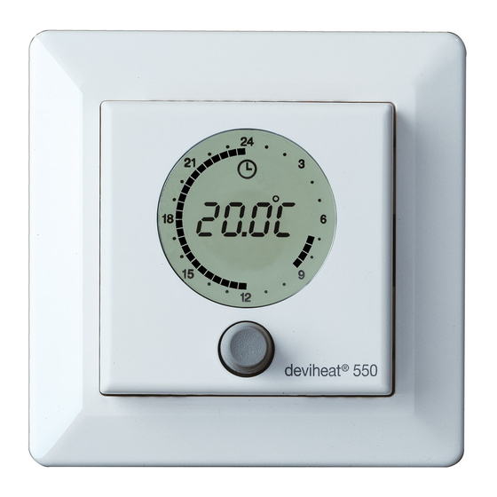
How to use your deviheat heating system ™ The function of the button The button can be turned both ways, is indicated by or the button can be pressed/held, is indicated by View of symbols in the display Symbol for Timer On Symbol for temperature below set-point…
-
Page 7
Daily operation devireg 540/550 has two temperature settings: ™ Constant temperature with the timer off. Can be used e.g. as ‘Party Mode’ or for con- stantly lowering the temperature when going on holiday. This is indicated by a continuous clock ring … Timer setting with automatic switching between economy and comfort temperature. -
Page 8
You want to raise the temperature … Turn clockwise to raise the tempera- ture. You want to lower the temperature … Turn counter-clockwise to lower the temperature. Economy set-back You want to switch on or off the timer between 00 and 07 function … -
Page 9
The marking on the clock-ring indi- cates when comfort temperature is chosen and when economy set-back is switched on. A fl ashing point indi- cates the actual clock (every half hour). If the temperature is lowered to mini- mum (+5ºC), a frost symbol will appear in the display, indicating that the thermostat will maintain minimum +5ºC in the room for frost protection. -
Page 10
Setting the clock & day You want to set/change the clock … (The clock is not set from the factory) 3 sec. Hold the button for 3 sec. The clock can now be set forward or back by turning the button to the right or left respectively. -
Page 11
Timer programming You want to set/change the economy set-back programme … (The timer is not set from the factory) Hold the button for 6 sec. The pro- 6 sec. gramme for economy set-back can now be edited. First, turn the button to choose the weekday which you want to programme … -
Page 12
The button is alternately turned and pressed to choose periods with econ- omy set-back and periods with com- fort temperature respectively. The programming switches between low (economy set-back) and high (comfort) temperature every time you press the button. And between every time you press, you can turn the button and choose the period of time. -
Page 13
Example When you enter the programming menu choose a day and press the button … Turn until you reach the fi rst time when you want comfort temperature, e.g. 06:00. Press … Turn until the temperature must be lowered again, e.g. 07:30. Press … -
Page 14
And turn to the next comfort period, e.g. 15:30, and press … Then, turn until you reach the time when the next lowering of the temperature must start, e.g. 22:30, and press … -
Page 15
If you continue to turn, the programme will automatically continue with the next day. This way, the programming can continue for the entire week. When you have ended the program- ming, the changes must be saved. 3 sec. This is done by holding the button for 3 sec. -
Page 16
CEE, and all relevant national laws which damage caused by others, or incorrect implies that: installation or any subsequent damage DEVI provides a warranty for devifl ex that may occur. If DEVI is required to ™ ™ ™… -
Page 17
Warranty is granted to: ™ Name: Address: Postal code: Phone: Please Observe! In order to obtain the DEVI Warranty, the following must be ™ carefully filled in. See other conditions on the overleaf. Electrical Installation by: Installation date: Type of thermostat:… -
Page 20: Connection Diagram
Connection diagram: Network connection devireg 550 ONLY ™…
-
Page 21
Technical specifi cations: Temperature range: +5º to +35°C or OFF Floor temperature limit: +20º to +50ºC Voltage: 180 — 250 V ~ 50/60 Hz Resistive load: 250 V ~ 16 A Inductive load: 1 A (power factor 0.3) Power consumption: <… -
Page 22
Fault: What to do: Confi gured as Master, Only one unit may be con- but can detect another fi gured as a Master Master unit Sensor fault Change the fl oor sensor fl oor sensor open circuit Sensor fault Change the fl oor sensor fl… -
Page 23: Error Messages
Error messages: devireg 540/550 has a built-in system that constantly ™ checks the heating system, the thermostat itself and a pos- sible network for any malfunctions. If an error occurs, the display will fl ash together with a reading of the detected fault, which will be shown indicated by the weekday numbers 1 to 7: Fault: What to do:…
-
Page 24
If more master units are confi gured on the network, an error message will fl ash in the display, and the unit will need to be reconfi gured. If a devireg 550 is confi gured as a slave unit, the following ™… -
Page 25
Network connections (devireg 550 ONLY): ™ The devireg 550 features a network capability. ™ All devireg 550’s installed in a building can be linked ™ together via the network facility, giving the possibility of central adjustment of programming and parameters e.g. clock setting. -
Page 26
Factory setting: The thermostat is preset with the following parameters: Operation Factory setting Choices Network type Alone Alone, Master or (devireg 550 ONLY) Slave ™ Temp. display Cº Cº or Fº Sensor Room + fl oor Room, fl oor or room + fl… -
Page 27
Finally, the type of clock must be set. Choose whether the clock must be 24 hours or 12 hours AM/PM. Turn to choose 12 or 24 hours, and press … To fi nish the basic setting, press the button, and the display will return to the daily operation menu. -
Page 28
In connection with the built-in Timer, the thermostat can be programmed to lower the temperature (LO), e.g. during the night. The range is 0ºC to -15ºC. Turn to choose economy set-back level, and press … (Choose -5ºC if the temperature must be lowered 5 degrees). -
Page 29
Offset (OFFS) can be used to adjust a variation between the thermostat and a thermometer in the room, if any. If the thermometer shows e.g. 1ºC more than the thermostat, it is pos- sible to adjust the offset with +1ºC. The range is -5.5ºC to +5.5ºC. -
Page 30
Maximum fl oor temperature is preset from the factory to 45ºC for cable temperature safety. Local building regulations must be observed, when chang- ing the maximum preset temperature. For wooden fl oor constructions DEVI recommend to limit ™ the temperature to maximum 27ºC. -
Page 31
devireg 540/550 is able to use two ™ sensors, one built-in sensor plus an external sensor which can be placed e.g. in the fl oor. Choose the sensor(s) which will be used for this heating system. Turn to choose Room Sensor (r S), Floor Sensor (FS) or both Room and Floor Sensor (rFS), and press … -
Page 32
Choose whether the thermostat must show Celcius or Fahrenheit degrees. Turn to choose Cº or Fº, and press … -
Page 33
devireg 550 ONLY: ™ The fi rst function to choose in the basic setting is whether devireg ™ must operate Alone or as Master or Slave thermostat. If several thermostats are linked in one network, only one of the thermo- stats can be choosen as Master ! For further information about network and Master/Slave, see section on… -
Page 34
Change of basic setting If it is necessary to change the basic setting, the button must be held for 12 sec. 12 sec. It is then possible to access the basic setting menu by choosing the code ! Turn to choose code … Choose the code: 0044 When the code is chosen, press the button … -
Page 35
devireg 540/550 is able to use two ™ sensors, one built-in sensor plus an external sensor which can be placed in the fl oor. Choose the sensor(s) which will be used for this heating system. Turn to choose Room Sensor (r S), Floor Sensor (FS) or both Room and Floor Sensor (rFS), and press … -
Page 36
Activating devireg 540/550 ™ When the thermostat is connected to the mains voltage for the fi rst time, a code must be chosen and the sensor(s) selected. Turn to choose code … Choose the code: 0044 When the code is chosen, press the button … -
Page 37
DO NOT over tighten ! -
Page 38
Reassemble the thermostat by fi rst placing the frame, then mount the display module and fi nally press the front cover into place. Note: The display must be gently remounted on the base module, ensuring that the 8-pin plug is placed accurately by using the four tabs sur- rounding it. -
Page 39
In order to get the best possible result when using the devireg 540/550, the thermostat ™ should be installed in the wall, following a few basic rules: Installation height, typically between 80-150 cm. On a wall NOT facing the outside On a wall where it will NOT be subjected to direct sunlight Away from windows/doors that will open… -
Page 40
Warning (devireg 550 ONLY): ™ Please note, when working on thermostats connected to a network, ensure that the mains supply for all thermostats in the network is disconnected before the work is started. Screw holes You can now mount the ther- mostat in the wall, by using any of the eight screw… -
Page 41
— A fl oor sensor is not present, and cannot be installed. — Choose Room sensor only in Basic Settings. — Be aware that temperature control is less accurate without the fl oor sensor. DEVI recommend that a fl oor sensor is ™… -
Page 42
Connection of the thermostat must be carried out as shown below. Mains supply NTC sensor 180-250 V 50/60 Hz Network Heating element connection Max. load 16 Amp. devireg 550 ONLY ™ As the devireg 540/550 is not equipped with an earth ™… -
Page 43
Remove the frame from the thermostat. Frame… -
Page 44
Remove the two screws, one in each side, and gently pull off the display module. Screws… -
Page 45
Installation of devireg 540/550: ™ When installing devireg 540/550 you must fi rst ™ dismantle the thermostat. Remove the front cover by gently pressing the release tab in the top (center hole), and lift out the cover. Release tab… -
Page 46
Table of contents Installation of devireg 540/550 ™ Activating devireg 540/550 ™ Change of basic setting Factory settings Network Error messages Technical specifi cations Connection diagram Please Note: The devireg 540/550 must be connected and the basic ™ setting must be done by an authorised electrician. In-appropriate installation and basic setting may cause damage to the heating system or fl… -
Page 48
Installation Instruction Installation Instruction Installation Instruction GB/DAS devireg 540/550 ™…
Инструкция По Применению Регулятора Температуры Devired 540
devireg™ 540 — это упрощенный вариант терморегулятора devireg™ 550. Он предназначен в основном для использования в составе электрической кабельной системы установленной как в качестве основного так и дополнительного отопления. Таймер позволяет задавать индивидуальные программы снижения температуры. Рекомендуется устанавливать терморегулятор на внутренней стене помещения, на высоте 0,8 — 1,5 м от пола, соблюдая несколько основных правил Терморегулятор комплектуется датчиком температуры пола и имеет встроенный датчик температуры воздуха. Регулятор имеет систему аварийного выключения при обрыве или коротком замыкании в цепи датчика температуры. Перед установкой терморегулятор необходимо частично разобрать. Для этого выполните следующие действия: 1. Снимите переднюю панель, слегка нажав отверткой на защелку через щель вверху корпуса, и снимите верхнюю панель. 2. Отверните два винта, аккуратно потяните и отсоедините дисплей, снимите декоративную рамку. 3. Подсоединение проводов к терморегулятору производится при отсутсвии напряжения в питающей сети. Внимание! Подключение терморегулятора к питающей сети должно производится квалифицированным электриком! Терморегулятор не имеет специального контакта для подключения «земли». Вывод экранирующей оплетки нагревательного кабеля должен соединяться с проводом «земля» питающей сети с помощью контакта вне терморегулятора. 4. Закрепите корпус терморегулятора в заранее установленной в стене стандартной монтажной коробке. Установите на место декоративную рамку. Очень осторожно поставьте на место дисплей, используя 4 направляющие так, чтобы 8-контактная розетка аккуратно присоединилась к разъему в корпусе регулятора. Заверните 2 винта, не затягивая их слишком сильно. 5. Установите на место верхнюю панель. Теперь терморегулятор можно будет настроить для работы. На передней панели терморегулятора расположены жидкокристаллический экран и ручка управления. С помощью ручки управления производятся все действия с терморегулятором. На ручку можно нажимать, а можно поворачивать против и по часовой стрелке. На экране отображаюся цифры и символы, по которым Вы сможете определить в каком режиме работы находится терморегулятор.
Электронный терморегулятор Devireg™ 610 ПАСПОРТ Продукция сертифицирована ГОССТАНДАРТом России в системе сертификации ГОСТ Р и имеет официальное заключение ЦГСЭН о гигиенической оценке. Содержание «Паспорта» соответствует техническому описанию производителя Содержание: 1. Сведения об изделии 1.1 Наименование 1.2 Изготовитель 1.3 Продавец 2. Назначение изделия, области применения 3. Номенклатура и технические характеристики 4. Устройство электронного терморегулятора Devireg™ 610 5. Принцип действия электронного терморегулятора Devireg™ 610 6. Правила выбора терморегулятора, монтаж и эксплуатация 6.1. Правила выбора терморегулятора 6.2. Монтаж терморегулятора 6.3. Эксплуатация терморегулятора 7. Комплектность 8. Меры безопасности 9. Транспортировка и хранение 10. Утилизация 11. Сертификация 12. Гарантийные обязательства 1. Сведения об изделии. 1.1 Наименование. Электронный терморегулятор Devireg™ 610. 1.2 Изготовитель. DEVI A/S, Ulvehavevej 61, DK-7100 Vejle, Дания. 1.3 Продавец. ООО «Данфосс», 143581, Российская Федерация, Московская область, Истринский район, сельское поселение Павло-Слободское, дер. Лешково, д.217. Тел.: +7 (495) 792 5757, факс:+7 (495) 540 7364. 2. Назначение изделия, области применения. Универсальный электронный терморегулятор с повышенной степенью защиты Devireg™610 (рис. 1) применяется для управления электрическими кабельными системами обогрева (КСО) различного назначения (табл. 1), а также системами охлаждения в диапазоне температур от -10оС до +50оС. Может также быть использован для управления другими системами электроотопления или системами отопления с электрическими блоками контроля. Рис. 1. Электронный терморегулятор Devireg™610. Поставляется в виде готового электронного блока, может монтироваться на стену или на трубу. Поставляется в брызгозазищенном исполнении (IP44) и может устанавливаться во влажных помещениях и на улице. Области применения электронного терморегулятора Devireg™ 316. Область контроля Контроль температуры поверхности пола или другого объекта с помощью выносного датчика. Контроль воздуха. температуры Таблица 1 Применение Управление системой «теплый пол» или системами подогрева других поверхностей. Управление системами кондиционирования и технологического подогрева или охлаждения. Обогрев резервуаров и трубопроводов водоснабжения и дренажа. Управление системой полного отопления помещения. Управление наружными антиобледенительными системами (крыши, ливневые водостоки, наружные площадки). 3. Номенклатура и технические характеристики. Электронный терморегулятор Devireg™610 обладает расширенными функциональными возможностями, что позволяет ограничиться одной модификацией. Технические характеристики электронного терморегулятора Devireg™610. Таблица 2 Параметр Характеристика Диапазон регулирования температур Напряжение питания Активная нагрузка Индуктивная нагрузка Гистерезис Работоспособность в диапазоне температур Переключатель Индикатор Тип датчика Крепление Класс защиты Типовое сопротивление датчика -10°С …+50°С 180 …250 В, ~50 Гц 10 А, 250 В 2 А, 250 В, cos φ = 0,3 0,4°С -30°С …+50°С NO/NC, трёхконтактное реле Двухцветный светодиод. NTC, на проводе 2,5 м, отрицательный температурный коэффициент На стену или на трубу IP 44 -10°C 66 кОм 0°C 42 кОм +25°C 15 кОм +50°C 6 кОм 4. Устройство электронного терморегулятора devireg™610. Терморегулятор Devireg™610 выполнен в виде аппарата, предназначенного для установки на стену или на трубу. Герметичный корпус – из ударопрочной пластмассы светло-серого цвета. На передней панели имеются ручка управления, светодиодный индикатор, выключатель питания. Блок питания терморегулятора – встроенный, с балластным конденсатором без гальванической развязки первичных и вторичный цепей. Коммутация нагрузки осуществляется электромагнитным реле. 5. Принцип действия электронного терморегулятора Devireg™ 610. Электронный терморегулятор Devireg™610 представляет собой аналоговый компаратор. На один из входов компаратора подается опорное напряжение, управляемое резистором-задатчиком температуры, ручка которого выведена на панель управления терморегулятора. На другой вход подается напряжение с терморезистора датчика температуры, через который пропускается стабилизированный ток. Силовым коммутирующим элементом регулятора является электромагнитное реле. В зависимости от поставленной задачи можно выбрать один из двух режимов работы терморегулятора: Ш включение нагревателя при падении температуры ниже заданной; Ш включение охладителя при повышении температуры выше заданной. 6. Правила выбора терморегулятора, монтаж и эксплуатация. 6.1. Правила выбора терморегулятора. Мультифункциональные возможности терморегулятора Devireg™610 позволяют применять его для решения многочисленных задач обогрева или охлаждения. В зависимости от поставленной задачи датчик терморегулятора может быть установлен в гофротрубке, предусматривающей его лёгкую замену («тёплый пол»), на поверхности обогреваемой трубы или резервуара (трубопроводы, ёмкости), на воздухе (антиобледенительные системы водостоков крыш и наружных площадок, основное отопление помещений). При коммутации нагрузки большой мощности без использования внешнего контактора следует учитывать ограничения, накладываемые контактной группой встроенного реле терморегулятора (см. Табл.2 – Активная нагрузка, Индуктивная нагрузка). 6.2. Монтаж терморегулятора. • Перед вскрытием корпуса терморегулятора установите ручку регулирования на минимальную температуру, т.е. -10оС. После закрытия корпуса убедитесь, что ручка регулирования поворачивается во всем диапазоне температур, от -10оС до +50оС. • При установке в ванных комнатах и других влажных помещениях необходимо соблюдать минимальное расстояние до водяной арматуры, предписываемое действующими «Правилами по устройству электроустановок». Регулятор подключается к сети через соответствующие аппараты защиты автоматический выключатель, УЗО и т.д. • Предварительно нанесенные заглушки входов для резиновых уплотнителей в нижней части корпуса удаляется с помощью отвертки и ножа. • Терморегулятор крепится на стену вертикально, после чего отверстия под шурупы заглушаются пробками (прилагаются в комплекте поставки). • Следует соблюдать рекомендованную фазировку при подключении к регулятору питающего сетевого напряжения. • Терморегулятор не должен крепится на вибрирующем основании. • При отоплении помещений выносной датчик температуры воздуха обычно располагается на внутренней стене на высоте 1-1,5 м над полом. Датчик не должен размещаться в непосредственной близости от приборов отопления, окон и дверей, и не должен подвергаться воздействию сквозняка или прямых солнечных лучей, а также быть закрытым шторами, полотенцами и т.д. • Провод датчика температуры можно наращивать до 50 м медным проводом сечением 1,5мм2, точность показаний при этом не снижается. Провод датчика не должен располагаться параллельно силовым сетевым кабелям во избежание нежелательных наводок. • При применении датчика температуры пола с укладкой в бетонный пол, датчик на проводе помещается в гофрированную пластмассовую трубку Ш16мм или более. Трубка должна быть защищена (заглушена) от попадания раствора внутрь. Трубка должна обеспечить свободную замену датчика через монтажную коробку или отверстие в стене. Минимальный радиус изгиба трубки 50мм. • Большие магнитные пускатели и другие электроприборы, создающие сильное магнитное поле не должны располагаться в непосредственной близости от терморегулятора. • Подключение согласно схеме А – режим «обогрев» (подключение нагревательных приборов), В – режим «охлаждение» (подключение кондиционера, вентиляции и т.д.) Нагрузка макс.10А Нагрузка макс.10А А. Рис.2. Схемы подключения Devireg™610. 6.3. Эксплуатация терморегулятора. В. Электронные терморегуляторы DEVI™ не требуют специального сервисного обслуживания. Необходимо лишь следить за чистотой наружных и внутренних поверхностей и перед началом каждого рабочего сезона подтягивать винты клеммников. При включении следует установить на терморегуляторе желаемую температуру. При плавном вращении ручки по часовой стрелке наступает момент, когда срабатывает реле (слышен щелчок) и загорается красный индикатор. При этом указатель ручки показывает на шкале температуру, измеряемую датчиком. Для систем «Тёплый пол», устанавливаемых в помещениях, следует выставить указатель ручки в положение +(26…32)°С в соответствии с рекомендациями СНиП и ВТО (см. раздел «Меры безопасности»). При первом включении вновь смонтированной системы “Теплый пол”, стабилизация температуры на заданном уровне произойдет в течение 1-3 суток. Это время, необходимое для удаления остаточной влаги из стяжки и прогрева строительных конструкций, зависит от конструкции пола и глубины залегания нагревательного кабеля. В случае обнаружения неисправности терморегулятора необходимо обратиться в сервисную службу компании (тел. (495)792-57-57). 7. Комплектность. Электронный терморегулятор Devireg™610 поставляется выносным датчиком температуры и инструкцией по установке. в комплекте с В качестве дополнительных принадлежностей к терморегулятору Devireg™610 могут поставляться: — крепление для установки на трубу; — наружный датчик температуры. Наружный датчик температуры IP44 может монтироваться отдельно или крепиться непосредственно на корпус терморегулятора. Установка датчика терморегулятора: температуры IP44 непосредственно на корпус Удалить предварительно насеченные заглушки входов небольшого диаметра в верхней части терморегулятора и в нижней части датчика. Установить черный соединительный патрубок в отверстие терморегулятора. Повернуть корпус наружного датчика до совмещения трех выступов на верхней части терморегулятора с тремя выемками на нижней части датчика. Подключить датчик к клеммам регулятора, обозначенным NTC. Закрепить раздельно наружный датчик и терморегулятор с помощью винтов и скобок. 8. Меры безопасности. Установка и подключение терморегулятора должны производиться в соответствии с Правилами устройства электроустановок (ПУЭ), Строительными нормами и правилами (СНиП) и Временными техническими требованиями к кабельным системам обогрева (ВТО КСО): • Правила устройства электроустановок (ПУЭ), Главгосэнергонадзор, Москва, 2001; • Строительные нормы и правила, СНиП 2.04.05-91∗, Госстрой России; • Временные технические требования к устройству специальных электроустановок с применением нагревательного кабеля, ВТТ КСО, 2003. Электронные терморегуляторы должны использоваться строго по назначению в соответствии с указанием в технической документации. 9. Транспортировка и хранение. Транспортировка и хранение электронного терморегулятора осуществляется в фабричной упаковке в соответствии с требованиями ГОСТ 15150-69, ГОСТ 23216-78, ГОСТ 51908-2002. 10. Утилизация. Утилизация изделия производится в соответствии с установленным на предприятии порядком (переплавка, захоронение, перепродажа), составленным в соответствии с Законами РФ №96-Ф3 “Об охране атмосферного воздуха”, №89-Ф3 “Об отходах производства и потребления”, №52-Ф3 “Об санитарно-эпидемиологическом благополучии населения”, а также другими российскими и региональными нормами, актами, правилами, распоряжениями и пр., принятыми во исполнение указанных законов. 11. Сертификация. Электронные терморегуляторы сертифицированы ГОССТАНДАРТом России в системе сертификации ГОСТ Р. Имеется сертификат соответствия, санитарно – эпидемиологическое заключение ЦГСЭН о гигиенической оценке. Имеется заключение «Пожполисерт» о том, что терморегуляторы не подлежат обязательной сертификации в области пожарной безопасности. 12. Гарантийные обязательства. Изготовитель поставщик гарантирует соответствие электронных терморегуляторов техническим требованием при соблюдении потребителем условий транспортировки, хранения и эксплуатации. Гарантийный срок эксплуатации электронных терморегуляторов — 2 года со дня продажи.

- Вводная часть инструкции по эксплуатации терморегулятора для теплого devireg ™ 540 — это упрощенный вариант терморегулятора devireg ™ 550. Таймер позволяет задавать индивидуальные программы снижения температуры. Регулятор имеет систему аварийного выключения при обрыве или.
- Питание регулятора. 180-250 В. 50/60 Гц. Кабель макс. нагрузка 16A. Датчик температуры. 7. Внимание! Терморегулятор devireg ™ 540 /550 не имеет.
- Тел.: +7 (495) 792 5757, факс:+7 (495) 540 7364. 2. Назначение охлаждения в диапазоне температур от -10оС до +50оС. Может также Области применения электронного терморегулятора Devireg ™ 316. Таблица 1 Силовым коммутирующим элементом регулятора является электромагнитное реле. В.
- Эти измерения считываются регулятором Devireg 850 на основании датчик измеряет температуру грунта, а другой датчик контролирует влажность.
- Installation Instructions Devireg 530, 531 and 532. RU UA Инструкция по установке. действия — поддержания заданной температуры воздуха в помещении. встроенным в корпус регулятора датчиком. *259 ф.+7 (095) 540 -73-64.
Оснащен встроенным датчиком температуры воздуха и датчиком температуры пола на проводе. Терморегулятор Devireg 540 применяется для систем.
Электронный терморегулятор Devireg ™ 610
![]()
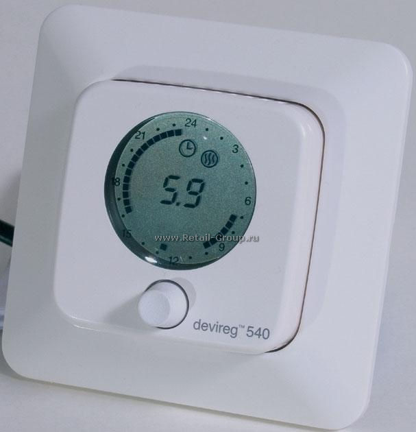
Table of Contents for DEVI devireg 540:
-
Example When you enter the programming menu choose a day and press the button … Turn until you reach the fi rst time when you want comfort temperature, e.g. 06:00. Press … Turn until the temperature must be lowered again, e.g. 07:30. Press … 13
-
Change of basic setting 15 If it is necessary to change the basic setting, the button must be held for 12 sec. It is then possible to access the basic setting menu by choosing the code ! Turn to choose code … Choose the code: 0044 When the code is chosen, press the button … 12 sec.
-
Choose whether the thermostat must show Celcius or Fahrenheit degrees. Turn to choose Cº or Fº, and press … 17
-
When the thermostat is connected to the mains voltage for the fi rst time, a code must be chosen and the sensor(s) selected. Turn to choose code … Choose the code: 0044 When the code is chosen, press the button … Now the sensors to be used, should be selected … Activating devireg ™ 540/550 13
-
User Instruction devireg ™ 540/550 GB/DAS
-
Daily operation 7 devireg ™ 540/550 has two temperature settings: (Display will indicate same temperature during both comfort and economy periods. But temperature will, during economy periods, be lowered according to the set-back level.) Constant temperature with the timer off. Can be used e.g. as ‘Party Mode’ or for con- stantly lowering the temperature when going on holiday. This is indicated by a continuous clock ring … Timer setting with automatic
-
The thermostat is preset with the following parameters: Operation Factory setting Choices Network type Alone Alone, Master or (devireg ™ 550 ONLY) Slave Temp. display Cº Cº or Fº Sensor Room + fl oor Room, fl oor or room + fl oor M
-
Remove the two screws, one in each side, and gently pull off the display module. Screws 5
-
Technical specifi cations: Temperature range: Floor temperature limit: Voltage: Resistive load: Inductive load: Power consumption: Battery back-up: Economy set-back: Offset: IP class: Type of sensor: Sensor value: +5º to +35°C or OFF +20º to +50ºC 180 — 250 V ~ 50/60 Hz 250 V ~ 16 A 1 A (power factor 0.3) < 500 mW 100 hours 0º to -30ºC -5.5º to +5.5ºC IP 30 NTC 15 kOhm / 25ºC 28
-
Timer programming 6 sec. You want to set/change the economy set-back programme … (The timer is not set from the factory) Hold the button for 6 sec. The pro- gramme for economy set-back can now be edited. First, turn the button to choose the weekday which you want to programme … Press the button to start the programming … 11
-
Installation of devireg ™ 540/550: When installing devireg ™ 540/550 you must fi rst dismantle the thermostat. Remove the front cover by gently pressing the release tab in the top (center hole), and lift out the cover. Release tab 4
-
The DEVI ™ Warranty is granted to: Name: Phone: Warranty Certificate Address: Postal code: Electrical Installation by: Type of thermostat: Installation date: Production code: Suppliers Stamp: Please Observe! In order to obtain the DEVI ™ Warranty, the following must be carefully filled in. See other conditions on the overleaf. DEVI DK · 7100 Vejle Phone +45 76 42 47 00 Fax +45 76 42 47 03
-
You have purchased a deviheat ™ 550 thermostat, which forms an integrated part of a deviheat ™ system, which we are certain will improve your home comfort and economy. deviheat ™ provides complete heating solutions with devifl ex ™ heating cables or devimat ™ heating mats, devireg ™ thermostats and devifast ™ fi tting bands. If, however, contrary to all expectations, a problem should occur with your heating system, we at
-
And turn to the next comfort period, e.g. 15:30, and press … Then, turn until you reach the time when the next lowering of the temperature must start, e.g. 22:30, and press … 14
Questions, Opinions and Exploitation Impressions:
You can ask a question, express your opinion or share our experience of DEVI devireg 540 device using right now.
Download or browse on-line these User Instruction for DEVI devireg 540 Thermostat.
Summary of Contents:
 |
[Page 1] DEVI devireg 540 User Instruction devireg ™ 540/550 GB/DAS |
 |
[Page 2] DEVI devireg 540 Introduction 3 Introducing devireg ™ 540/550 4 How to use your deviheat ™ heating system 6 Daily opera… |
 |
[Page 3] DEVI devireg 540 You have purchased a devireg ™ 540/550 thermostat, which forms an integrated part of a deviheat™ system. DEVI ™ has developed the devireg ™ 540/550 to make your fl oor heating an even more environmentally correct way of heating your ho… |
 |
[Page 4] DEVI devireg 540 Introducing devireg ™ 540/550 devireg ™ 540 is an advanced temperature controller, with a built-in Timer. devireg ™ 550 ONLY: devireg ™ 550 is an adaptive temperature controller, specially designed for fl oor heating systems. The devir… |
 |
[Page 5] DEVI devireg 540 All this means that as soon as you have set your devireg ™ 550 at your desired comfort temperature, you do not have to do anything else. devireg ™ 550 will automatically adjust the heating to meet your requirements for comfort and economy, … |
 |
[Page 6] DEVI devireg 540 How to use your deviheat ™ heating system The function of the button The button can be turned both ways, is indicated by or the button can be pressed/held, is indicated by Symbol for frost protection Symbol for Timer On Numerical display for tim… |
 |
[Page 7] DEVI devireg 540 Daily operation 7 devireg ™ 540/550 has two temperature settings: (Display will indicate same temperature during both comfort and economy periods. But temperature will, during economy periods, be lowered according to the set-back level.) Constan… |
 |
[Page 8] DEVI devireg 540 8 You want to raise the temperature … Turn clockwise to raise the tempera- ture. You want to lower the temperature … Turn counter-clockwise to lower the temperature. You want to switch on or off the timer function … Press the button to switch … |
 |
[Page 9] DEVI devireg 540 The marking on the clock-ring indi- cates when comfort temperature is chosen and when economy set-back is switched on. A fl ashing point indi- cates the actual clock (every half hour). If the temperature is lowered to mini- mum (+5ºC), a frost s… |
 |
[Page 10] DEVI devireg 540 Setting the clock & day You want to set/change the clock … (The clock is not set from the factory) Hold the button for 3 sec. The clock can now be set forward or back by turning the button to the right or left respectively. Changing the week … |
 |
[Page 11] DEVI devireg 540 Timer programming 6 sec. You want to set/change the economy set-back programme … (The timer is not set from the factory) Hold the button for 6 sec. The pro- gramme for economy set-back can now be edited. First, turn the button to choose the week… |
 |
[Page 12] DEVI devireg 540 The button is alternately turned and pressed to choose periods with econ- omy set-back and periods with com- fort temperature respectively. The programming switches between low (economy set-back) and high (comfort) temperature every time you pres… |
 |
[Page 13] DEVI devireg 540 Example When you enter the programming menu choose a day and press the button … Turn until you reach the fi rst time when you want comfort temperature, e.g. 06:00. Press … Turn until the temperature must be lowered again, e.g. 07:30. Press … |
 |
[Page 14] DEVI devireg 540 And turn to the next comfort period, e.g. 15:30, and press … Then, turn until you reach the time when the next lowering of the temperature must start, e.g. 22:30, and press … 14 |
 |
[Page 15] DEVI devireg 540 If you continue to turn, the programme will automatically continue with the next day. This way, the programming can continue for the entire week. End When you have ended the program- ming, the changes must be saved. This is done by holding the butt… |
 |
[Page 16] DEVI devireg 540 You have purchased a deviheat ™ 550 thermostat, which forms an integrated part of a deviheat ™ system, which we are certain will improve your home comfort and economy. deviheat ™ provides complete heating solutions with devifl ex ™ … |
 |
[Page 17] DEVI devireg 540 The DEVI ™ Warranty is granted to: Name: Phone: Warranty Certificate Address: Postal code: Electrical Installation by: Type of thermostat: Installation date: Production code: Suppliers Stamp: Please Observe! In order to obtain the DEVI ™ Warran… |
 |
[Page 18] DEVI devireg 540 … |
 |
[Page 19] DEVI devireg 540 … |
 |
[Page 20] DEVI devireg 540 29 Connection diagram: Network connection devireg ™ 550 ONLY |
 |
[Page 21] DEVI devireg 540 Technical specifi cations: Temperature range: Floor temperature limit: Voltage: Resistive load: Inductive load: Power consumption: Battery back-up: Economy set-back: Offset: IP class: Type of sensor: Sensor value: +5º to +35°C or OFF +20º to +50�… |
 |
[Page 22] DEVI devireg 540 2 6 5 No: Fault: What to do: Confi gured as Master, but can detect another Master unit Sensor fault fl oor sensor open circuit Sensor fault fl oor sensor shortcircuit Only one unit may be con- fi gured as a Master Change the fl oor sensor Chan… |
 |
[Page 23] DEVI devireg 540 Error messages: devireg ™ 540/550 has a built-in system that constantly checks the heating system, the thermostat itself and a pos- sible network for any malfunctions. If an error occurs, the display will fl ash together with a reading of the d… |
 |
[Page 24] DEVI devireg 540 If more master units are confi gured on the network, an error message will fl ash in the display, and the unit will need to be reconfi gured. If a devireg ™ 550 is confi gured as a slave unit, the following set-up parameters are controlled … |
 |
[Page 25] DEVI devireg 540 The devireg ™ 550 features a network capability. All devireg ™ 550’s installed in a building can be linked together via the network facility, giving the possibility of central adjustment of programming and parameters e.g. clock setting. Th… |
 |
[Page 26] DEVI devireg 540 The thermostat is preset with the following parameters: Operation Factory setting Choices Network type Alone Alone, Master or (devireg ™ 550 ONLY) Slave Tem… |
 |
[Page 27] DEVI devireg 540 Finally, the type of clock must be set. Choose whether the clock must be 24 hours or 12 hours AM/PM. Turn to choose 12 or 24 hours, and press … 22 To fi nish the basic setting, press the button, and the display will return to the daily operati… |
 |
[Page 28] DEVI devireg 540 21 In connection with the built-in Timer, the thermostat can be programmed to lower the temperature (LO), e.g. during the night. The range is 0ºC to -15ºC. Turn to choose economy set-back level, and press … (Choose -5ºC if the temperature m… |
 |
[Page 29] DEVI devireg 540 Offset (OFFS) can be used to adjust a variation between the thermostat and a thermometer in the room, if any. If the thermometer shows e.g. 1ºC more than the thermostat, it is pos- sible to adjust the offset with +1ºC. The range is -5.5ºC to +… |
 |
[Page 30] DEVI devireg 540 Due to different fl oor constructions it is possible to choose a maximum fl oor temperature (Mt) in the fl oor which cannot be exceeded. The temperature range is 20ºC to 50ºC. Turn to choose maximum fl oor tem- perature, and press … 19 P… |
 |
[Page 31] DEVI devireg 540 18 devireg ™ 540/550 is able to use two sensors, one built-in sensor plus an external sensor which can be placed e.g. in the fl oor. Choose the sensor(s) which will be used for this heating system. Turn to choose Room Sensor (r S), Floor Sen… |
 |
[Page 32] DEVI devireg 540 Choose whether the thermostat must show Celcius or Fahrenheit degrees. Turn to choose Cº or Fº, and press … 17 |
 |
[Page 33] DEVI devireg 540 devireg ™ 550 ONLY: The fi rst function to choose in the basic setting is whether devireg ™ 550 must operate Alone or as Master or Slave thermostat. If several thermostats are linked in one network, only one of the thermo- stats can be cho… |
 |
[Page 34] DEVI devireg 540 Change of basic setting 15 If it is necessary to change the basic setting, the button must be held for 12 sec. It is then possible to access the basic setting menu by choosing the code ! Turn to choose code … Choose the code: 0044 When the code … |
 |
[Page 35] DEVI devireg 540 devireg ™ 540/550 is able to use two sensors, one built-in sensor plus an external sensor which can be placed in the fl oor. Choose the sensor(s) which will be used for this heating system. Turn to choose Room Sensor (r S), Floor Sensor (FS… |
 |
[Page 36] DEVI devireg 540 When the thermostat is connected to the mains voltage for the fi rst time, a code must be chosen and the sensor(s) selected. Turn to choose code … Choose the code: 0044 When the code is chosen, press the button … Now the sensors to be used, … |
 |
[Page 37] DEVI devireg 540 DO NOT over tighten ! 12 |
 |
[Page 38] DEVI devireg 540 Reassemble the thermostat by fi rst placing the frame, then mount the display module and fi nally press the front cover into place. Note: The display must be gently remounted on the base module, ensuring that the 8-pin plug is placed accurately… |
 |
[Page 39] DEVI devireg 540 In order to get the best possible result when using the devireg ™ 540/550, the thermostat should be installed in the wall, following a few basic rules: Installation height, typically between 80-150 cm. On a wall NOT facing the outside On a wal… |
 |
[Page 40] DEVI devireg 540 You can now mount the ther- mostat in the wall, by using any of the eight screw holes in the base module. Screw holes 9 Warning (devireg ™ 550 ONLY): Please note, when working on thermostats connected to a network, ensure that the mains sup… |
 |
[Page 41] DEVI devireg 540 When installing the devireg ™ 540/550 you need to choose the type of heating and thus which sensors should be used. DEVI ™ recommend always to install the fl oor sensor ! Comfort Heating: — Constant temperature on the fl oor in e.g. bathroo… |
 |
[Page 42] DEVI devireg 540 Connection of the thermostat must be carried out as shown below. Mains supply 180-250 V 50/60 Hz Heating element Max. load 16 Amp. Network connection devireg ™ 550 ONLY NTC sensor 7 As the devireg ™ 540/550 is not equipped with an earth ter… |
 |
[Page 43] DEVI devireg 540 Remove the frame from the thermostat. Frame 6 |
 |
[Page 44] DEVI devireg 540 Remove the two screws, one in each side, and gently pull off the display module. Screws 5 |
 |
[Page 45] DEVI devireg 540 Installation of devireg ™ 540/550: When installing devireg ™ 540/550 you must fi rst dismantle the thermostat. Remove the front cover by gently pressing the release tab in the top (center hole), and lift out the cover. Release tab 4 |
 |
[Page 46] DEVI devireg 540 Installation of devireg ™ 540/550 4 Activating devireg ™ 540/550 13 Change of basic setting 15 Factory se… |
 |
[Page 47] DEVI devireg 540 … |
 |
[Page 48] DEVI devireg 540 Installation Instruction GB Installation Instruction GB Installation Instruction GB/DAS devireg ™ 540/550 08095121 · 03.03 |
Документация
Каталоги и инструкции
Инструкции по установке терморегуляторов:
- Инструкция Devireg 130, 131, 132 ( 418 Kb)
- Инструкция Devireg 530, 531, 532 (984 Kb)
- Инструкция Devireg 535 (834 Kb)
- Инструкция Devireg 540, 550 ( 863 Kb)
- Инструкция Devilink ( 2,5 Mb)
- Инструкция Devireg 316 (224 Kb)
- Инструкция Devireg 330 ( 523 Kb)
- Инструкция Devireg 610 (192 Kb)
- Инструкция Devireg 850 ( 1,4 Mb)
- Руководство пользоваталея Devireg Touch (2107 Kb)
- Инструкция по установке Devireg Touch (7706 Kb)
- Инструкция_-_Veria_control_B45 ( 239 Kb )
- Инструкция_-_Veria_control_T45.pdf ( 313 Kb )
Информационные материалы:
- Пособие «Кабельные электрические системы отопления» (4,4 Mb)
- Каталог продукции DEVI «Кабельные электрические системы отопления» (1,8 Mb)
- Защита холодильных камер от замерзания (532 Kb)
Сертификаты
Сертификаты на терморегуляторы:
- Сертификат соответствия требованиям безопасности на терморегуляторы электронные торговых марок Danfoss, DEVI (963 Kb)
- Об обязательной сертификации электронных терморегуляторов, электросушилок для полотенец, тепловентиляторов напольных, кабелей нагревательных, предназначенных исключительно для установки в вещество по теплопроводности класса бетон (2.92 Mb)
- Об обязательной сертификации терморегуляторов (266 Kb)
- Сертификат соответствия требованиям безопасности на терморегуляторы электронные торговой марки VERIA (696 Kb)
Паспорта на нагревательные кабели:
- Deviflex DTIP-10 ( 467 Kb)
- Deviflex DTIP-18 ( 962 Kb)
- Deviflex DSIG-20 ( 987 Kb)
- Deviflex DTCE ( 250 Kb)
- Deviflex DPH-10 ( 1 Mb)
- Deviflex DTIV-9 ( 350 Kb)
- Veria_flexicable_20 ( 393 Kb )
Паспорта и инструкции на нагревательные маты:
- Devimat DSVF-150 ( 555 Kb)
- Devimat DTIF-150 ( 496 Kb)
- Veria Quickmat 1c ( 4,4 Mb )
- Veria Quickmat 2c ( 4,3 Mb )
Сертификаты на нагревательные кабели и маты:
- Сертификат соответствия требованиям безопасности на нагревательные кабели SMT, FLX, HSX, RGS, Devi-Pipeguard, Devi-Iceguard, CSR, DanFoss SLP, DanFoss SLI (446 Kb)
- Сертификат пожарной безопасности на нагревательные кабели Devi-Pipeguard, Devi-Iceguard (371 Kb)
- Сертификат пожарной безопасности на нагревательные кабели ELSR-H, ELSR-N, ELSR-M, ELSR-L, ELSR-R, ELSR-W, ELSR-SH, ELKM-A, ELKM-H, ELKM-HS, ELKM-Q, ELKM-AS, ELKM-AG, ELKM-AE, ELK-AS, ELK-AG, ELW-VA, ELK-H, ELK-AE, ELK-HS, ELW-H, ELW-IIS, ELW-GN, ELW-GS, ELK-MI/F, ELK-Q, El-Floor Twin, El-Floor Single, ELP, El-Rail, ELW-3 (357 Kb)
- Сертификат соответствия требованиям безопасности на нагревательные маты и кабели DEVI (871 Kb)
- Сертификат соответствия требованиям безопасности на нагревательные маты и кабели VERIA (756 Kb)
- Сертификат соответствия требованиям нормативных документов на нагревательные маты и кабели VERIA (584 Kb)
- Об обязательном подтверждении соответствия нагревательных матов и кабелей DEVI, VERIA (292 Kb)
Сертификаты на нагревательные системы Devidry:
- Сертификат пожарной безопасности на плиты монтажные Devicell Dry, Devidry FM (292 Kb)
«Партнер ДЕВИ» – официальный дилер теплых полов в Нижнем Новгороде, сотрудничающая с ведущей компанией по производству и продаже теплых полов DEVI.
Контакты
- Email devinn@bk.ru
- Телефон +7 (951) 903-16-34
- Телефон +7 (951) 903-16-34
- Адрес г. Нижний Новгород, ул. Генкиной, 41