
-
Уже зарегистрированы? Войти
-
Регистрация
Изменение в правилах «Опознайки»
Один объект для опознания — одна тема.
Запрещается размещать групповые фотографии или несколько разных объектов для опознания.
Информация о файле
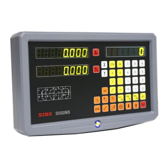
Инструкция на китайский УЦИ на русском. Инструкция переведена в формате брошюры, т.е. после распечатки сшить согласно нумерации страниц.
-
Уже зарегистрированы? Войти
-
Регистрация
Изменение в правилах «Опознайки»
Один объект для опознания — одна тема.
Запрещается размещать групповые фотографии или несколько разных объектов для опознания.
Информация о файле
Инструкция на китайский УЦИ на русском. Инструкция переведена в формате брошюры, т.е. после распечатки сшить согласно нумерации страниц.
- Manuals
- Brands
- SINO Manuals
- Other
- SDS2MS
- Operation manual
-
Contents
-
Table of Contents
-
Troubleshooting
-
Bookmarks
Quick Links
SINO
DIGITAL READOUTS
SDS2MS
Operation Manual
Iran agent
Tel: 021 66 3939 00
Mob: 0912 147 3023
www.Sino.ir
GUANGZHOU LOK SHUN CNC EQUIPMENT LTD.
Summary of Contents for SINO SDS2MS
-
Page 1
SINO DIGITAL READOUTS SDS2MS Operation Manual Iran agent Tel: 021 66 3939 00 Mob: 0912 147 3023 www.Sino.ir GUANGZHOU LOK SHUN CNC EQUIPMENT LTD. -
Page 2
It is recommended that: ● Instructions for panel keys of the SDS2MS digital display meter that is applicable to this manual are listed in P1~4 of the above Section 1. ● Read through follow safety precautions and Section 2( see P57~61), which are very important to the safe operation of your digital display meter. -
Page 3
for battery replacement when using it again. Notes: ● Disconnect power plug promptly if the digital display meter emits smog or peculiar smells, when an electric shock or fire may be caused when continuing to use it. Please contact Guangzhou Lokshun CNC Equipment Ltd. or dealer and never attempt to repair it by yourself. -
Page 4
Illustration of Panel and Keyboard… -
Page 5
Illustration of Panel and Keyboard Caption of the Keyboard of SDS2MS Keys for Axis selection Returning the displayed Value to zero(X Axis ) Returning the displayed Value to zero(Y Axis ) Entry keys for digits ÷ ÷ × Operation Key (in Calculation… -
Page 6
Illustration of Panel and Keyboard Entry key plus or minus symbol ± Key for entering data Function key for getting one half Key for the conversion the meter System/ British system display Function key for Sleep Function key for 200 zero Position R angular ARC function key (ARC Function key) -
Page 7
Illustration of Panel and Keyboard Progressive inner chamber processing function key; In calculation function as cosine trigonometric function key Tool compensation function key; In calculation function as tangent trigonometric function Key for the conversion of relative/absolute display Key for the selection of upper/lower term or plane procession… -
Page 8: Table Of Contents
Catalog Catalog A. Basic Function …………………………………………………… 1 B. Smooth R ………………………………………………………….13 C. Simple R …………………………………………………………..22 D. Hole Drilling Along An Oblique Line ……………………………29 The Function For 200 Point ………………………………………33 F. PCD Circle Equally Dividing Holes………………………………42 G. Angular Surface Processing ………………………………………46 H.
-
Page 9: A. Basic Function
A. Basic Function A. Basic Functions Iran agent Tel: 021 66 3939 00 Mob: 0912 147 3023 www.Sino.ir…
-
Page 10
A. Basic Function We take pleasure to tell you that this machine tool optical digital display ruler device you are using is the one most popular in Europe. You will be able to use this device easily after you have read this manual thoroughly. -
Page 11
A. Basic Function 4) Setting counts direction of axis Y linear encoder. Setting method alike axis X. , next step 5) choose compensation type choose line error compensation “LINEAR”; choose Segmented error compensation “SEGMENT”; ,next step Press 6) Self test. twice, the Self-test program started then key to quit. -
Page 12
A. Basic Function 4) Key ,Enter the value(If the entered value is wrong, key and enter the correct one again) 5) Key , (If any mistake is found now, repeat steps 3~5). 6) Move the machine table to the position of 13, and the processing at Point B can start. -
Page 13
A. Basic Function 6) Move the machine tool to Position D. 7) Return to the absolute modeMove the machine tool to Position E. Note: The resetting in the absolute and the relative display mode must be done separately. In absolute display mode, “ALE” is displayed on Message Screen.
-
Page 14
A. Basic Function between two points is to be found. 1) Move the tool along the direction of arrow and let it come to touch the one and the other edges of the working piece, then determine the center position. 2) Key axis key 3) Key 4) Move the machine tool to bring the… -
Page 15
A. Basic Function L—the actually metered length (mm) L’—the displayed value on digital display meter (mm) S—the actually factor (mm/m), «+» symbol means the actual length is larger, and «-» symbol means the actual length is smaller. Compensation range: -1.500 mm/m~+1.500 mm/m Example: The Actual metered length of the machine tool machine table is 1000 mm, and the display value on the digital display meter is 999.98 mm. -
Page 16
A. Basic Function L: The distance of effective range of raster ruler L1: Length of the compensation segment L2: Effective distance of the compensation segment Set up according to the sketch map 1. The parameter set-up method is as follows: Move the raster ruler to the smallest end of the coordinate data Enter into the ALE right-angle coordinate system… -
Page 17
A. Basic Function Move towards the positive direction of X axis of the machine tool and search for the 1st absolute zero of the raster ruler as the mechanical origin. After find the origin, then auto enter the next step for data input. This time the X-axis displays the raster ruler fact value, and Y-axis displays the former compensation value(if the readout is first compensated, the Y-axis display a uncertain value). -
Page 18
A. Basic Function Input the compensation setup of the 4th segment Press Press , and enter into the next set-up point 10) Input the compensation setup of the 5th segment Press Press , and enter into the next set-up point 11) Input the compensation setup of the 6th segment Press After the setup is finished, press… -
Page 19
A. Basic Function Segmented compensation value is found according to the wrong mechanical coordinate, thus there is big error of the displayed coordinate. The method of finding mechanical origin is as follows: 1.Move the raster ruler to the position which is initially set up as the mechanical origin, and then set up Segmented compensation. -
Page 20
The switch on the back panel of the digital display box may once be turned off during the processing of a working piece. It is true that the SDS2MS Series digital box has its interruption memory, but the machine tool may have been moved after the event. -
Page 21
B. Smooth R B.Smooth R Iran agent Tel: 021 66 3939 00 Mob: 0912 147 3023 www.Sino.ir… -
Page 22
The advanced smooth R arc Calculation function provided in SDS2MS model digital display box makes it possible to complete the processing of a single piece such as moulding copper electrode easily and quickly with a universal milling machine. -
Page 23: Anti Clockwise
B. Smooth R 2) Let us recognize the plane coordinate and the start and end angles of a circular arc. In Plane XY、XZ or YZ, the coordinate of a point is its position with respect to the zero point on the plane. The coordinate of zero point O:(0,0) The coordinate of Point A:(20,20) The coordinate of Point B:(30,10)
-
Page 24
B. Smooth R 3) The procedure in using the Arc R Calculation function. As shown in the figures(a)、(b)and (c), reset all the axes after finishing the installation of Tool and the related tool setting (assign the position of the tool after tool setting as the zero point). -
Page 25
B. Smooth R This determines the position of the first cut feed in the processing of circular arc. As show in Fig.(b), the start angle is 0° if the arc is to be processed from Point E to Point F, and 90° when from F to E. 8. -
Page 26
B. Smooth R If finish the tool setting as shown in Fig. (b). ± ± φ5 φ5 6) Enter the radius of the circle. 7) Enter the diameter of the tool.Enter the maximal cut. 9) Enter the start angle of the arc. 10) Enter the end angle of the arc.
-
Page 27
B. Smooth R 12) It is display that the processing start at the first point. Tool setting as Fig. (a) Tool setting as Fig. (b) 13) Move the machine tool to bring the display value on X- and Y-axes into zero, reach the start point of R. 14) Key and the position of any processing point may come to be displayed, and you can move the machine tool to bring the displayed values… -
Page 28
B. Smooth R 3) Select processing plane. 4) Select Plane XZ. 5) Enter the position of the circle center ± 6) Enter the radius of the circle. *Now a circular arc mill is used, finish the tool setting as shown in Fig. (b) 7) Enter the diameter of the tool. -
Page 29
B. Smooth R 12) It is display that the processing start at the first point. 13) enter the processing and display the first point. 14) Press to display the every processing position, Move the machine tool to bring the display value on X- and Y-axes into zero, that’s the each point of You may quit ARC function at will, just key… -
Page 30
C. Simple R C.Simple R Iran agent Tel: 021 66 3939 00 Mob: 0912 147 3023 www.Sino.ir… -
Page 31
C. Simple R Simple Arc R Calculation function: One who is not quite at home in the concepts of plane coordinates will feel difficult in using smooth arc function. If the arc to be processed is simple enough, and the required smoothness is average, the simple arc R function may be a good choice. -
Page 32
C. Simple R 2. Select the processing way among the preset 1 to 8 ways, the prompt: “WHICH”. 、 3. Select the processing plane, XY XZ or YZ. (ARC-XY) (ARC-XZ) (ARC-YZ) 4. Enter the of the circular arc (RDDIUS) 5. Enter the diameter of the tool (TL DLA): When processing the arc in Planes XZ and YZ, end mill is used and the processing in carried by the end edge of the tool, so the diameter valve to be entered should be zero.(refer to step 5 in the operation procedure of the smooth R function). -
Page 33
C. Simple R L= R L= R+ the radius of the tool L= R+ the radius of the tool L= R L= R+ the radius of the tool L= R+ the radius of the tool L1= R L1= R L2= the radius of the tool L2= the radius of the tool L1= the radius of the tool… -
Page 34
C. Simple R 3) Select the processing plane 4) Select Plane XZ 5) Enter the radius of the circular arc 6) Enter the radius of the tool 7) Enter the maximal cutStart processing Point A as the start point(0,0) Point B as the start point(0,0) 9) Refer to the display, move the machine tool to bring the displayed value on X axis into zero, then turn the Z axis star wheel to let the machine table rise or…
-
Page 35
C. Simple R *Take the processing of an inner circular arc as example: 1) At first, align the tool to face just the start point(Point A or Point B), to enter ARC function. Select the simple function, key 2) Select the way of the R processing Point A is the start point, key Point A is the start point, key 3) Select the processing plane… -
Page 36
C. Simple R 9) Refer to the display, move the machine tool to bring the displayed valve on X axis into zero, then turn the Z axis star wheel to let the machine table rise or drop by the displayed value in Y axis. 10) Key and the position of next/last point will display. -
Page 37: D. Hole Drilling Along An Oblique Line
D. Hole Drilling Along An Oblique Line D. Hole Drilling Along An Oblique Line Iran agent Tel: 021 66 3939 00 Mob: 0912 147 3023 www.Sino.ir…
-
Page 38
D. Hole Drilling Along An Oblique Line The function of hole drilling along an oblique line Normally, for processing the working pieces shown in the right figure the operator must calculate out the distance between two neighboring holes in X- and Y- axes; an easy 30°… -
Page 39
D. Hole Drilling Along An Oblique Line 5) Enter the number of holes 6) The position of the first hole is displayed, enter processing state. 7) Key to display the position of next processing point, and then move the machine tool to bring the displayed value on both X- and Y-axes into zero. You can quit the function at will, just key For the working piece in (a), it is more convenient to select “MODE L”. -
Page 40
D. Hole Drilling Along An Oblique LineKey to display the position of next processing point, and then move the machine tool to bring the displayed value on both X- and Y-axes into zero. You can quit the function at will, just key…
-
Page 41: E . The Function For 200 Point
The Function For 200 Point E. The Function For 200 Point Subsidiary Zero Positions Iran agent Tel: 021 66 3939 00 Mob: 0912 147 3023 www.Sino.ir…
-
Page 42
The Function For 200 Point 200 subsidiary zero position function: 200 auxiliary zero position function: also is called 200 user Coordinate System (UCS) function. ALE: Absolute Coordinate System. ALE is the “reference” system. All 200 UCS are defined relative to the ALE. ALE is confirmed in the initialization of the work piece process, which doesn’t change if the work piece no changed. -
Page 43
The Function For 200 Point every UCS taking a subsidiary zero position as its original points to perform the processing when need. 2. In the display mode of every UCS, processing with various special function can be performed. Ⅲ. The setting of subsidiary zero position There are two methods of setting subsidiary zero position: the one is entering the position of the subsidiary zero position directly, the other is resetting once a subsidiary zero position is reached. -
Page 44
The Function For 200 Point 1) After setting the zero position in the absolute mode, the system automatically perform a keeping in memory operation, in order that once a power interruption happen in the course the zero position may be tracked back. 2) Enter the UCS display mode. -
Page 45
The Function For 200 Point corresponding UCS. This is because the subsidiary zero position is taken as the original point of the UCS under the relative display mode. In Fig. (1), we can see that Point O is at the position(-80, -30) with respect to Point 1, (-70, -40) with respect to Point 2, and (-60, -40)with respect to Point 3. -
Page 46
The Function For 200 Point 7) Enter the display mode of the second UCS.Clear, set the second subsidiary zero point. 9) Return to the absolute state display mode. Continue to touch three times key 10) Move the machine table of the machine tool to Point 3.
-
Page 47
The Function For 200 Point entering the desired UCS. When using key just key and under the prompt “ZERO No” enter the number of the desired UCS. For the related operations, the operator may refer to “5 Absolute/relative/user coordinate display mode” under “Ⅰ.Usage” of “A. Basic Function”. -
Page 48
The Function For 200 Point 10) Enter the display mode of the third UCS. 11) Move the machine tool to point 3. X axis display 0, Y axis display 0. 12) Enter PCD function, process the six small holes distribute uniformly on the circle center at Point 3. -
Page 49
The Function For 200 Point original subsidiary zero position. 3. Turn to one half during a subsidiary zero position is being used “1/2” function may be used under UCS display mode. Turning to one half under the UCS display mode using a subsidiary zero position is actually also resetting a new subsidiary zero position. -
Page 50: F. Pcd Circle Equally Dividing Holes
F. PCD Circle Equally Dividing Holes F.PCD Circle Equally Dividing Holes Iran agent Tel: 021 66 3939 00 Mob: 0912 147 3023 www.Sino.ir…
-
Page 51
F. PCD Circle Equally Dividing Holes Circular arc equally Dividing Function(PCD Function) This function may be used to divide a circular arc equally, for example in the processing of drilling holes distributed uniformly on a flange. After selecting this function, the message window will prompt for various parameters to be defined for the operator. -
Page 52
F. PCD Circle Equally Dividing Holes to enter PCD function. 2) Enter the center position of the circular , next step. 3) Enter the diameter of the circular arc. , next step. 4) Enter the number of points equally dividing the arc. Fig. -
Page 53
F. PCD Circle Equally Dividing Holes 7) Enter processing The display result for dividing the arc into5 equal sections. The display result for dividing the arc Into 6 equal sections. 9) Key and the position of next processing point will be displayed, just move the machine tool to bring the displayed values on both axes into zero to reach the corresponding processing position. -
Page 54: G. Angular Surface Processing
G. Angular Surface Processing G. Angular Surface Processing Iran agent Tel: 021 66 3939 00 Mob: 0912 147 3023 www.Sino.ir…
-
Page 55
G. Angular Surface Processing Angular Surface Processing When the processing of a rather large angular surface is one part of job, the angular processing function can make the job much easier. Ⅰ. Aligning for the bank angle: When the processing surface is Plane XY as in the case of the fitting shown in Fig. -
Page 56
G. Angular Surface Processing 2) Select Plane XY. 3) Enter the angle of the angle surface 4) Move the machine table along X axis. Let the metering tool come just in contact with the working piece, and adjust the scale reading into zero, then move the machine table an arbitrary distance along X axis. -
Page 57
G. Angular Surface Processing 1. Select Plane XZ or YZ. 2. Enter the diameter of the tool (DIA). 3. Enter the start point (ST POS). 4. Enter the end point (ED POS). 5. You may quit the angular surface processing function at will, just key Refer to the example: 1)Align for the bank angle, finish tool setting, and key… -
Page 58
G. Angular Surface Processing and respectively the position of last/next processing point will be displayed. You may quit the angular processing function at will, just key… -
Page 59: H. The Progressive Progressing
H. The Progressive Progressing H. The Progressive Progressing of rectangular Inner chamber Iran agent Tel: 021 66 3939 00 Mob: 0912 147 3023 www.Sino.ir…
-
Page 60
H. The Progressive Progressing The progressive progressing of rectangular inner chamber When the job is to process the inner chamber of the fitting shown by the working drawing of Fig. (1), the progressive inner chamber processing function may be used; and referring to the prompts the operator can operate easily. As shown in Fig. -
Page 61
H. The Progressive Progressing 5) Enter processing state. 6) Move the machine table to bring the displayed values on both X- and Y-axes into zero. 7) Key to display the processing position of next step, refer to the prompts and move the machine to bring the displayed values on both X- and Y- axes into zero. -
Page 62: I. The Function Calculator Function
I. The Function Calculator Function I. The Function Calculator Function Iran agent Tel: 021 66 3939 00 Mob: 0912 147 3023 www.Sino.ir…
-
Page 63
I. The Function Calculator Function The Calculation function Some time it is necessary to calculate out some values during the processing, SDS2MS Series digital display boxes are provided with simple Calculation function. The details are as following: All the resulted value is displayed on X axis. -
Page 64
I. The Function Calculator Function Make the following calculation: √ =31.623 The distance AB in the figure = × — √ × 31.623 90° Display for the result: Transfer the value 31.623 to Y axis. As shown in the figure, the distance AB=31.623, the tool is at Point A, move the machine table to bring the displayed value into zero, the position of Point B is reached, the processing of Hole B may start. -
Page 65: J. N3 Function
J. N3 Function J. N3 Function Iran agent Tel: 021 66 3939 00 Mob: 0912 147 3023 www.Sino.ir…
-
Page 66
J. N3 Function the function is suit for Z axis vertical slope machining. There are four machining mode, as following example: ① ΔZ=0.1 A=60˚ ② ΔZ=0.1 A=120˚ ③ ΔZ=-0.1 A=-120˚ ④ ΔZ=-0.1 A=-60˚… -
Page 67
J. N3 Function Operation steps was show as fallow: (Take the processing plane XZ as an example) 1) Move the tool to the start point, (plane YZ). ,enter N3 function. 2) Key ,select the processing plane. 3) Key 4) Select plane XZ,Key to ensure 5) Enter the angle. -
Page 68
J. N3 Function 9) Point 3, move axis X to 0, move axis Z 0.1mm forward. ,next point. The last point 10) The last point, move axis X to 0, move axis Z 0.1mm forward. ,quit N3 function, 11) Key digital readout show the current XY value. -
Page 69: Additional Sheet
Additional sheet Additional sheet: Ⅰ. What the user must know: 1. The digital display box must be handle carefully. 2. The box must be grounded properly. 3. Power voltage selection: AC 80V~260V 50 Hz~60 Hz 4. Power consumption: 25VA 5. Working temperature: 0℃~45℃ 6.
-
Page 70
Additional sheet Ⅱ. Trouble shooting and handling: Troubleshooting of Grating Ruler and Digital display Meter The following troubleshooting is primary only. If there are still problems, do not dismantle them by yourself, seek help from our company or corresponding agents. Symptom of Source of failure Troubleshooting… -
Page 71
Additional sheet Symptom of Source of failure Troubleshooting failure Grating 1. Grating ruler falls outside the 1. Repair the grating ruler. ruler does usable range of length, not count reading head cracked up. 2. Reading head of grating ruler 2. Repair the grating ruler. rubs ruler enclosure, and aluminum chips piled up. -
Page 72
Additional sheet Ⅲ. Structural principle Our linear encoder and digital readout are high technologic production that is combined with photo electronic technology, precision mechanical technology, microelectronic technology computer technology, and so on. The customer without being trained may not repair this system. -
Page 73
Additional sheet Ⅴ. product packaging bill 1、a piece of SDS2MS series digital readout 2、a piece of power wire 3、a copy of operating instruction 4、A copy of verified certificate 5、A piece of dustproof cover 6、a piece of wire clip 7、a piece of bracket… -
Page 74
Additional sheet Dear users: Thank the purchase and use of Guangzhou Lokshun CNC Equipment Ltd’ product! In order to make our services make you more satisfied after the purchase, please read the following instructions: Products shall be delivered with «Three Guarantees» and 15-day limited replacement and free repair within the period of one warranty year (from date of sale). -
Page 75
Iran agent Tel: 021 66 3939 00 Mob: 0912 147 3023 www.Sino.ir LOK SHUN CNC EQUIPMENT LTD. http://www.sino-ld.com Add:No.16wordshop,3rd Industrial Park,Xilang East Road,Liwan District,Guangzhou p.c:510385 Fax: (020)81617180 Tel: (020)81617181,81622771 Hotline: (020)81622533 E-mail:infos@sino-ld.com…
Suggest us how to improve StudyLib
(For complaints, use
another form
)
Your e-mail
Input it if you want to receive answer
Станкостроительный завод Каталог станков Токарные станки c ЧПУ Устройство цифровой индикации Цифровая индикация Документация
- Обзор
- Модельный ряд
- Фото
- Документация
Документация на устройство цифровой индикации
 Руководство по эксплуатации SDS6
Размер файла: 14.2 МБ
Дата публикации: 01 февраля 2016 года 10:41
Описание: УЦИ SINO серий SDS2, SDS6. на русском языке
Руководство по эксплуатации УЦИ SDS3
Размер файла: 3.5 МБ
Дата публикации: 09 февраля 2016 года 13:18
Описание: на русском языке
Руководство по установке оптических линеек серии КА
Размер файла: 6 МБ
Дата публикации: 01 февраля 2016 года 10:41
Описание: Для серий KA200, KA300, KA500, KA600. на русском языке. Постоянно обновляется и дополняется для удобства пользователей и простоты установки
SNS-3V 3-осевой цифровой индикаторный монитор DRO для токарно-фрезерный станок, для линейных стеклянных шкал
Посылка входит:
1 шт. SNS-3V 3-осевой дисплей (с руководством пользователя, монтажный рычаг, винтовой пакет)
Спецификация DRO
Цифровая индикация (DRO) в серии SNS-это высокоточный инструмент, который может использоваться на токарном станке, шлифовальном станке, фрезерном станке, расточном станке, электроэрозионном станке и т. д.
Цифровая индикация соответствия SNS-3V для всех китайских производственных весов, таких как Sino, Easson, ational, HXX, Sinpo и т. д.
Характеристики продукта
Дисплей на английском языке
Функция самодвижения со средним разделением
Функция метрического/имперского преобразования
Функция преобразования абсолютного/относительного счета
1000 групп нулевой памяти
Функциональный калькулятор
Функция обработки поверхности дуги
Функция PCD
Функция обработки Канта
Функция PLD
Функция компенсации ошибок станка
Функция EDM (опция с дополнительным)
Функция
1. Нулевая Очистка
2. Сброс
3. Мм/дюйм режим
4. Преобразование координат ABS/INC
5,200 наборов вспомогательных баз
6. Отключение памяти при отключении питания;
7. Центр 1/2
8. Компенсация ошибок вкладыша
9. Режим сна
10. Очистка 200 наборов базы Sdm;
11. Режим ABS/INC
12. Калькулятор
13. Сверление окружности
14. Сверление косой линии
15. Обработка наклонной плоскости
16. Обработка круговой дуги
17. Функция токарного станка (сопоставление)
18. Прямоугольный люмен постепенной обработки
19. Цифровая фильтрация
20. Вибрационная фильтрация
21. Инструкция по эксплуатации
22. Функция Y + Z
Технические параметры
1. Диапазон напряжения: 85-250 В переменного тока/50 Гц-60 Гц
2. Потребляемая мощность: 25ва
3. Координаты: 1/2/3/4
4. Дисплей: 8-битный цифровой дисплей
5. Входной сигнал: квадрат TTL
6. Частота входного сигнала: 100 кГц
7. Разрешение считывания: 10 мкм, 5 мкм, 2 мкм, 1 мкм, 0,5 мкм


Отгрузка
При размещении заказа, пожалуйста, выберите способ доставки и оплатите заказ, включая стоимость доставки (за исключением бесплатной доставки). Мы отправим товары в течение срока доставки после оплаты.
Мы не гарантируем срок доставки для всех международных перевозок из-за различий в сроках таможенного оформления в отдельных странах, что может повлиять на то, как быстро ваш продукт будет проверен.
Обратите внимание, что покупатели несут ответственность за все дополнительные таможенные сборы, брокерские сборы, пошлины и налоги на импорт в вашу страну. Эти дополнительные расходы могут быть предъявлены вам к оплате при доставке. Мы не возмещаем расходы за отклоненные поставки.
Стоимость доставки не включает налоги на импорт, и покупатели несут ответственность за таможенные пошлины.
Возврат
Мы делаем все возможное, чтобы обслужить наших клиентов по высшему разряду.
Мы вернем вам деньги, если вы вернете товары в течение 15 дней с момента получения по любой причине. Однако покупатель должен убедиться, что возвращенные товары находятся в исходном состоянии. Если товары повреждены или потеряны при возврате, покупатель будет нести ответственность за такой ущерб или потерю, и мы не возместим покупателю полную стоимость. Покупатель должен подать иск на транспортную компанию, чтобы возместить стоимость ущерба или убытков.
При возврате товара Покупатель несет расходы за обратную доставку.
Гарантия
Мы предлагаем the1-month бесплатную замену. Покупатели могут потребовать замену в течение 15 дней с момента получения товара. Покупатель должен возвратить нам товар в первоначальном состоянии и нести расходы по доставке при возвращении.
Мы также предоставляем 12-месячное бесплатное обслуживание. Покупатель должен возвратить нам товар в первоначальном состоянии и нести расходы по доставке при возвращении. Если какая-либо деталь должна быть заменена, Покупатель также должен оплатить расходы на замену деталей.
Перед возвратом товара, пожалуйста, подтвердите обратный адрес и способ доставки с нами. После того, как товар будет передан компании-перевозчику, пожалуйста, отправьте нам почтовый идентификатор. Как только мы получим товары, мы как можно скорее их отремонтируем или обменяем.
Отзывы
Удовлетворение ваших запросов и положительная обратная связь очень важны для нас. Пожалуйста, оставьте отзывы в и 5 звезд, если вы удовлетворены нашими товарами и услугами.
Если вы остались недовольны качеством товара и обслуживания, не торопитесь подтверждать получение товара и писать негативный отзыв. Сначала свяжитесь с нами. Мы сделаем все возможное, чтобы решить любые проблемы и предоставить Вам лучшее обслуживание клиентов.
2V/3V MULTIFUNCTION
DIGITAL READOUTS
Operation Manual
(Version V1.0)
Dear Users:
Thank you for purchasing multifunction series digital readouts.
Digital readouts are used in a wide variety of application.
These include machine tools, infeed axes, measuring and inspection equipment, EDM, dividing apparatuses, setting tools, and measuring stations for production control. In order to meet the requirements of these applications, many encoders can be connected to the digital readouts.
Read all the instructions in the manual carefully before used and strictly follow them. Keep the manual for future references.
Safety attention: cooling liquid must be avoid. In case of any smoke or peculiar smell from the digital readout, please unplug the power plug immediately, otherwise, fire or electric shock may be caused. In such a case, do not try to repair it, please contact the Company or distributors.
Linear Scale. When it is in use, if the connection between the
Linear Scale and the digital readout is broken or damaged externally, incorrect measuring values may be resulted. Therefore, the user should be careful. fault or injury may occur. In case of any abnormal condition, please contact the Company or distributor. do not use a Linear Scale of other brand. Because the performan ce, specification and connection of the products of different and can not be connected without the instruction of specialized technical personnel, otherwise, trouble will be caused to the digital readout.
1
Contents
1. Illustration of Panel and keyboard ………………………………………4
2. Caption of the keyboard ……………………………………………………5
3. Parameters settings …………………………………………………………7
3.1
Parameters setup routine entrance ……………………………7
3.2 Parameters Settings
Description ……………………………………7
3.2.1 Setting the type of the DRO ………………………………………7
3.2.2 Signal Interfa ce Type ………………………………………………7
3.2.3
Restore Factory Settings……………………………………………8
3.2.4 Shrinkage Ratio enable or disable ………………………………8
3.2.5 Setting
Compensation Type …
………………………………………8
3.2.6 Setting RI Mode………………………………………………………9
3.2.7 Setting Linearity
Compensation …
…………………………………9
3.2.8 Setting the Shrin kage Ratio ……………………………………10
3.2.9 Setting the Reso lution ……………………………………………10
3.2.10 Toggle Betwween R/ D Display Mode …………………………11
3.2.11 Setting Positive Dir ection for Counter…………………………11
3.2.12 Setting Z axis Dial …………………………………………………11
3.2.13
Setting the Rotary Radius of the Workpiece ………………12
3.2.14
Setting the Angle Display Mode…………………………………12
3.2.15 Setting the Baudrat e of RS_232 ………………………………12
3.2.16 Setting the Absolute Zeroing enable or disable ……………13
3.2.17 Setting the Absolute form the Special Function……………13
3.2.18 Setting the Calcula tor Display Mode …………………………13
4、General Operations …………………………………………………………14
4.1 Zeroing……………………………………………………………………14
4.2 Preset Data to Designated Axis ……………………………………14
4.3 Toggle Display Unit between inch and mm………………………14
4.4 Absolute/Incremental/200 groups SDM …………………………15
4.5 1/2 Function……………………………………………………………15
4.6 Clear All SDM Datum…………………………………………………16
4.7 Sleeping Mode …………………………………………………………16
4.8
Power Interruption Memory …………………………………………16
4.9 Search the Absolute Refer ence Point of Scale …………………17
2
Contents
4.10 Non Linear Error Compensation …………………………………20
5、200 Groups SDM coordinate………………………………………………21
5.1 Zeroing at the Current Point………… ………………………………21
5.2 Preset datum of SDM coordinate……………………………………22
6、Special Function………………………………………………………………24
6.1 Circumference Holes Processing ……………………………………25
6.2 Linear Holes Processing ………………………………………………28
6.3 ARC Processing ………………………… ………………………………30
6.4 Oblique Processing ……………………………………………………39
6.5 Slope Processng…………………………………………………………43
6.6 Chamber Processing………… …………………………………………44
6.8 The Tool Diameter Compensation Function ……………………45
6.7 Digital Filter of the Grinding Machine ……………………………46
6.8 Lathe Function ………………………………………………………47
6.8.1 200 sets TOOL Libs …………………… …………………47
6.8.2 Taper Function ………………………………… ………………48
6.8.3 R/D Function ……………………………………………………49
6.8.4 Y + Z Function ( only applicable to : 3 axes Lathe)
………49
6.10 EDM…………………………………………… …………………………50
7、Calculator………………………………………………………………………56
8、Appendix ………………………………………………………………………57
3
Illustration of Panel and keyboard
THREE AXIS PANEL
X
0
Y
Z
0
0
X
Y
Z
MM
REF
SDM
ABS
7
4
1
0
R
8
5
2
9
6
3
SIFT
TWO AXIS PANEL
CTR
SIN
M1
COS
M2
TAN
M3
ENT
SIFT
X
0
MM
Y
Z
X
Y
Z
REF
SDM
ABS
7
4
1
0
R
8
5
2
9
6
3
CTR
SIN
M1
COS
M2
TAN
M3
ENT
4
Keyboard Description
X Y
X
0
Y
0
Z
Z
0
Caption of the keyboard
Keys for axis selection
Zero select axis
Enter +/- sign
Enter decimal point
0 1 2 3 4
Entry keys for numbers
5 6
7 8 9
CTR
AC
Operation key (in Calculation function key)
Enter or quit calculating state
Cancel incorrect operation
Calculate inverse trigonometric
Square root
REF
SDM
R
ENT
MM
Confirm operation
Toggles between inch and millimeter units.
Press when ready to identify a reference mark.
Function keys for 200 sub datum
ARC cutting function holes displayed equally on a circle holes displayed equally on a line
5
SIN
M1
COS
M2
TAN
M3
ABS
CALL
TOOL
EDM
SIFT
1
2
NP
Caption of the keyboard
Calculate trigonometric or Slope
Processing function key
Calculate trigonometric or rectangular inner chamber processing function key
Calculate trigonometric or the tool diameter compensation function key
Toggle between ABS/INC coordinate
Stroll up or down to select
Taper measured function key
Tool library call key
Opens the tool table.( lathe)
EDM function key
Filter display function key
Half a display value of an axis
Non Linear Error Compensation function keys
6
Parameters settings
3、Parameters settings。
3.1、Parameters setup routine entrance。
Press or
ENT
to enter initial system a nd self-check after DRO powers on in 1 second, then Parameters settings display in the
Parameters window.press to select the item you want to chang.
If you want to quit initial setting, press until “QUIT” appears in message window and press
ENT
. You can also press to quit initial setting.
3.2 Parameters Settings
Description
3.2.1
Setting the type of the DRO.
The type of the DRO will be display on the right window.
then press the key
ENT
to select the correct type.
the following system item will be set:
“MILL-3” means the DRO type is 3-axis milling machine table;
“MILL-2” means the DRO type is 2-axis milling machine table;
“LATHE-2” means the DRO type is 2-axis lathe table;
“LATHE-3” means the DRO type is 3-axis lathe table;
“GRIND” means the DRO type is Grind table;
“EDM” means the DRO type is EDM table;
X
0
MILL-3
ENT X
0
MILL-2
3.2.2 Signal Interface Type
Message window displays “ SEL AXIS”which indicates the step is to Sensor input signal mode. Press
X
0
to change the signal mode for X axis;Press Y
0
to change the signal mode for Y axis;Press Z
0
to change the signal mode for Z axis;Example for X axis:
Press X
0
to scroll through the Rotary encode type, the Linear encode type, the Rotary rdius type.
X window displays the Signal type.
7
Parameters settings
“LInER” means the Signal type is linear encode type ;
“EnCOdE “ means the Signal type is Rotary encode type;
“RdIUS” means the Signal type is Rotary rdius type ;
Example: currently in the linear encode type, to toggle to the Rotary encode type;
LINER
X
0
SEL AXIS
X
0
ENCODE
X
0
SEL AXIS
3.2.3 Restore Factory Settings:
Clear all data except DRO type.DRO will load default setup for parameter.After loading default setup,user must search RI once to enable resuming ABS dadum function;otherwise to resume the datum by RI is unable;
Message window displays “ ALL CLR”,press
ENT
and message windows display “PASSWORD”indicating the operator to input password; Press 2000 +
ENT
in turn to load default value;
X
0
ALL CLR ENT
X
0
CLR OK
3.2.4 Shrinkage Ratio enable or disable.
Message window displays “ SRK OFF”to disable Shrinkage rate function. Press
ENT
to enable Shrinkage rate function in Message window displays “ SRK ON”:
X
0
SRK OFF ENT
X
0
SRK NO
3.2.5 Setting
Compensation Type
Message window displays“ SEL COMP” which indicates the step is to compensation type
. Press X
0
to change the compensation type
for X axis;Press
Y
0
to change the compensation type
for Y axis;Press Z
0
to change the compensation type
for Z axis;Example for X axis:
Press X
0
to scroll through the not compesation type, the Linear compesation type, the non-linear compesation type
.
8
Parameters settings
“no-CO” means the compesation type is not compesation type;
“LInE-CO” means the compesation type is linear compesation type.
“non-LinE”means the compesation type is non-linear linear compesation type;
Example for X axis: currently in the not compesation type, to toggle to the linear compesation type;
NO—CO
X
0
SEL COMP LINE-CO
X
0
NO—CO
Y
0
X
Y 7 8 9
CTR
INV
X
0
NO—CO
Y
0
X
Y 7
SEL COMP
CTR
8 9
INV
3.2.6 Setting RI mode
Message window displays “ REF_R”or “REF RAB” which indicates the step is to RI Mode. Press
ENT
to change the RI mode.
“REF_R” means the RI mode is wave of single R;
“REF_RAB” means the RI mode is wave of A B R with AND gate;
X
0
ENT
X
0
REF RAB
3.2.7 Setting Linearity
Compensation.
Message window displays “ LIN COMP” which indicates the step is to Linearity Compensation .
Compensate the linear error to make display value equals to standard value.
The calculation of compensation rectifying coefficient:
(Measurement – Standard value) x 1000.000
Coefficient = ___________________________________________
Standard value
Example for X axis:
Measurement 200.020mm
Standard value 200.000mm
Rectifying coefficient=(200.020-200)* 1000 /200 =-0.01mm/m
Input compensation rectifying coefficient 0.01 as follow:
0.000
X
0
LIN COMP
X 0
0.010
X
0
0.000
Y
0
X
Y 7 8 9
CTR
INV
0.010
Y
0
9
Parameters settings
3.2.8 Setting the Shrinkage Ratio
Press until “ SHRINK” appears in message window;
Dimensions of the finished product
Shrinkage radio = _____________________________________
Dimensions of the working piece
Set the shrinkage radio 1.005 as follow;
1.000
X
0
SHRINK
X 0
1.005
X
0
1.000
Y
0
X
Y 7 8 9
3.2.9 Setting the Resolution
CTR
INV
1.000
Y
0
Press until “RESOLUTE” appears in message window;
When selecting the LINEAR encode, the resolution will be set as follow: m;
There are 11 types of resolution:
0.1u;0.2um;0.5um;1um;2um;2.5um;5um;10um;20um;25um;50u
Press X
0
to change the resolution for X axis;Press Y
0
to change the resolution for Y axis;Press to change the resolution for Z axis;
Set the resolution 5.0um to 1.0um for X axis:
5.0
X
0
5.0
Y
0
X
Y 7
RESOLUTE
CTR
INV
1.0
X
0
5.0
Y
0
X
Y 7
RESOLUTE
8 9
CTR
INV 8 9
When selecting the rotary encode, the resolution will be set as follow:
Input the rotary encode parameter value .
5.0
X
0
RESOLUTE
Y 1 0 0 0 0
5.0
X
0
1000
Y
0
X
Y
7 8 9
CTR
INV
10000
Y
0
10
Parameters settings
3.2.10 Toggle Betwween R/D Display Mode
Press until “R OR D” appears in message window. X window, Ywindow, Z window displays ‘0’ or ‘1’ separately.
‘0’is mode R, which means the dispay value equals the actual measurement. ‘1’ is mode D where the display value equals the double actual measurement. Press X
0
to change the R/D for X axis;Press
Y
to change the R/D for Y axis;Press Z
0
to change the
R/D for Z axis; as follow:
0
X
0
R OR D 1
X
0
R OR D
X
Y
CTR
0
Y
0
7 8 9
INV
3.2.11 Setting Positive Direction for Counter
0
Y
0
X
Y
7 8 9
CTR
INV
Press until “ DIRECTE” appears in message window.
Direction ‘0’ means the display value will increase when scale moves form right to left and decrease when scale moves from left to right. Direction ‘1’ means the display value will increase when scale moves form left to right and decrease when scale moves from right to left.
Press X
0
to change the Direction for X axis;Press
Y
0
to change the Direction for Y axis;Press
Z
0
to change the Direction for Z axis; as follow:
0
X
0
DIRECTE 1
X
0
DIRECTE
0
Y
0
X
Y 7 8 9
3.2.12 Setting Z axis Dial
Press
CTR
INV
0
Y
0
X
Y 7 8 9
until“Z DIAL” appears in message window.
CTR
INV
Z axis dial should be set if Z axis is emulated for 2 axis milling and only install linear scale for X,Y axis. Z axis dial means the distance the
Z axis travels when screw runs a revolution.
11
Parameters settings
Set the Z axis Dial 2.5mm as follow ;
5.000
X
0
Z DIAL
2 5
0 0
ENT
2.500
X
0
3.2.13 Setting the Rotary Radius of the Workpiece
Press until“RDIUS” appears in message window.
The Rotary rdius type is used perimeter to measure angle.
Input the Rotary Radius parameter value 2000mm as follow:
X
0
RDIUS
Y 1 0 0 0
ENT
1000.000
Y
0
X
Y
7 8 9
CTR
INV
X
0
2000.000
Y
0
3.2.14 Setting the Angle Display Mode
Press until“ANG DISP” appears in message window.
Press X
0
to change the angle display mode for X axis;Press to change the angle display mode for Y axis;Press Z
0
to change the angle display mode for Z axis; Example for X axis:
“0.0000” means the angle mode is Circulating DD;
“0000.0000” means the angle mode is Incremental DD;
“0.00.00” means the angle mode is Circulating DMS;
“0000.00.00”means the angle mode is Incremental DMS;
0.0000
X
0
ANG DISP
Y
0
X
Y
7 8 9
CTR
INV
3.2.15 Setting the Baudrate of RS_232
0000.00.00
X
0
Y
0
X
Y 7
ANG DISP
8 9
CTR
INV
Press until“BAUDRATE” appears in message window.
Set the Baudrate 115200 as follow ;
9600
X
0
BAUDRATE
1 1 5 2 0 0
115200
X
0
12
Parameters settings
3.2.16 Setting the Absolute Zeroing enable or disable
Press until“ABS_ZERO” appears in the message window.
‘0’means operation the ABS zeroing and preset data will be enable in the normal display state.
‘1’ means operation the ABS zeroing and preset data will be disable in the normal display state.
Press
X
0
to change the absolute zeroing mode for X axis;Press
Y
0
to change the absolute zeroing mode for Y axis;Press Z
0
to change the absolute zeroing mode for Z axis; Example for X axis.
0
X
0
ABS ZERO 1
X
0
ABS ZERO
0
Y
0
X
Y
7 8 9
CTR
INV
0
Y
0
X
Y 7 8 9
CTR
INV
3.2.17 Setting the Absolute form the Special Function
Press until“ABS_ASST” appears in message window.
‘0’ means only special function position value is display in the
Special Function operation.
‘1’ means special function position value + ABS position value is display in the Special Function operation.
Press X
0
to change the absolute mode for the Special Function will be set as follow:
0
X
0
1
X
0
3.2.18 Setting the Calculator display Mode
Press until“CTR_MODE” appears in message window.
‘0’ means the calculator display value at the X window in the disply; ‘1’ means the calculator display value at the message window in the disply;
Press X
0
to change the calculator display mode will be set as follow:
0
X
0
1
X
0
13
General Operations
4、General Operations;
4.1 Zeroing
Zero the designated axis in normal display state.Zeroing is used to set the current point as datum point as follow; key Y axis zero
0.000
0.000
X
0
Y
0
0.000
Press AC + X
0
or Y
0
or Z
0
will be return to the original data before the reset。
4.2 Preset Data to Designated Axis
Preset a value to current position for a designated axis in normal display state.
25.400
50.800
76.200
Z
0
X 1 8 0
Y 5 8 6
Z 8 8 8
0 1 0 ENT
0 1 0 ENT
6 6 0 ENT
180.010
586.010
888.660
Z
4.3 Toggle Display Unit between inch and mm
Length can be displayed either in “mm”(metric) or “inch”
(imperial). Display unit can be toggled between mm and inch.
Example: Display value toggle from mm to inch;
25.400
50.800
76.200
Z
0 mm
MM inch
1.00000
2.00000
3.00000
Z
Example: Display value toggle from inch to mm;
1.00000
2.00000
3.00000
Z
0 inch
MM mm
25.400
50.800
76.200
Z
0
14
General Operations
4.4 Absolute/Incremental/200 groups SDM
Function:The DRO has 3 coordinate display modes: the absolute mode (ABS); the incremental mode (INC) and 200 goups
Second Data Mamory (SDM) with the range of 00 to 99.Zero point of work-piece is set at the origin point of ABS coordinate. The relative distance between datum of ABS and SDM remains unchanged when ABS datum is changed.
1. Toggle from ABS to INC coordinate;
0.0000
X
0
ABS
ABS
INC
12.000
X
0
INC
0.0000
Y
0
X
Y
CTR
INV
18.000
7 8 9
2. Toggle from INC to ABS coordinate;
12.000
X
0
INC
ABS
INC
0.000
Y
0
X
0
X
Y 7 8 9
ABS
CTR
INV
18.000
Y
0
X
Y 7 8 9
CTR
INV
3. Toggle from SMD to ABS coordinate;
0.000
100.000
X
0
SDM 1
ABS
INC
0.000
Y
0
X
0
X
Y 7 8 9
ABS
CTR
INV
200.000
Y
0
X
Y 7 8 9
CTR
INV
0.000
Y
0
X
Y 7 8 9
4.5 1/2 Function
Function: Set the center of work piece as datum by halving the displayed value.
Example: Set the center of rectangle as datum as the right figure.
Steps:
1、Touch one side of the workpiece with the TOOL,then zero the X axis。
CTR
INV
25.400
76.200
X
0
Y
0
X
0
0.000
76.200
X
0
Y
0
15
General Operations
2、Take the TOOL to the opposite side of the workpiece and touch it.
Then press +
1
in turn to value the X axis display value.
800.000
76.200
X
0
Y
0
X
400.000
76.200
X
0
Y
0
3、Move the maching table until “0.000”is display in X axis window. The position is the work-piece’s center.
4.6 Clear All SDM datum.
In ABS mode, to continuously press ten times will cause to clear all the datum for 200 sets SDM. Message window displays “SDM
CLR”.
4.7 Sleeping Mode
In not ABS Mode, pressing the key
REF can turn off all the display and the DRO accessing to the Sleeping Mode, then pressing this key again will cause the DRO back to the working Mode. In the Sleeping
Mode the DRO is still in working state and actually records the TOOL movement.
Example: In not ABS Mode, to access the sleeping Mode by pressing the key
REF
. In Sleeping Mode, pressing the key
REF to quit the sleeping Mode.
4.8 Power Interruption Memory.
The memory is used to store the settings of the DRO and machine reference values when power is turn off.
16
General Operations
4.9 Search the Absolute Reference Point of Scale
During the daily machining process, it is very common that the machining cannot be completed within one work shift, and hence the
DRO have to be switched off after work, or power failure happen during the machining process which is leading to lost of the workpiece datum
(workpiece zero position), the re-establishment of workpiece datum using edge finder or other method is inevitably induce higher machining in accuracy because it is not possible to re-establish the workpiece datum exactly at the previous position. To allow the recovery of workpiece datum very accurately and no need to reestablish the workpiece datum using edge finder or other methods, every Linear scale have a ref point location which is equipped with ref position to provide datum point memory function.
The working principal of the ref datum memory function are as follows.
Since the ref point of Linear scale is permanent and fixed, it will never change or disappear when the DRO system is switched off.
Therefore, we simply need to store the distance between the ref point and the workpiece datum (zero position) in NON-Volatile memory. Then in case of the power failure or DRO being switched off, we can recover the workpiece datum (zero position) by presetting the display zero position as the stored distance from the ref point.
An absolute datum should be set when a work-piece is machined.
There are three mode operation (REF、AB、LEF_AB):
Example: to store the X axis work datum.
X axis ref mark position
(permanent and fixed)
Linear Scale
Workpiece
Work piece datum
(ABS zero)
Distance between the ref point and workpiece datum
17
Example for REF mode :
General Operations
1、DRO is set in ABS coordinate. Press
REF
, then the message window display “REF”.
0.000
X
0
ABS
REF X
0
REF
2、Message window displays “REF”, Press
ENT
until“FD_REF” appears in message window.
X
0
ABS
REF
0.000
X
0
FD REF
3、Select the axis which need search RI. For instance : selsct X axis, then press
X
. “X_REF” is displayed in message window, and
X axis window flashes.
0.000
X
0
FD REF
X
0.000
X
0
X REF
0.000
Y
0
X
Y 7 8 9
CTR
INV
0.000
Y
0
X
Y 7 8 9
CTR
INV
4、 Move the machine table .The buzzer sounds when RI is searched, then X window stops flashing and displays the value of the current position .the DRO returns normal display state. Then message window displays “FIND_X”.
Example for AB mode :
1、 DRO is set in ABS coordinate. Press
REF
, then the message window display “REF”.
0.000
X
0
ABS
REF
0.000
X
0
REF
2、Press
X
0
, then the massage window display “AB”.
REF
X
0
AB
3、Message window displays “AB”, Press
ENT
until“FIND_AB” appears in message window.
X
0
AB
ENT
0.000
X
0
FIND AB
18
General Operations
4、Select the axis which need search RI. For instance : selsct X axis, then press
X
. “X_REF” is displayed in message window, and X axis window flashes.
0.000
X
0
FIND AB
X
0.000
X
0
X_AB
0.000
Y
0
X
Y
7 8 9
CTR
INV
0.000
Y
0
X
Y
7 8 9
CTR
INV
5、 Move the machine table .The buzzer sounds when RI is searched, displays the value of the current position for the absolute datum zero. the DRO returns normal display state. Then message window displays
“FIND_AB”.
Example for LEF_AB mode :
1、 DRO is set in ABS coordinate. Press
REF
, then the message window display “REF”.
0.000
X
0
ABS
REF
X
0
REF
2、Press , then the message window display “AB”.
X
0
REF
X
0
3、Message window displays “LEF_AB”, Press
ENT
until“ZERO_AB” appears in message window.
X
0
ENT
120.000
X
0
4、Move the machine table to be set zero position piont. then press
X , X axis will be zeroing . the current position for the absolute datum zero. the DRO returns normal display state.
120.000
X
0
ZERO AB
X
0.000
X
0
NOTE:
Linear range without reference point location of the user
19
General Operations
4.10 Non Linear Error Compensation
First compensation Type ( Linear or Non-Linear) in parameter setting must be set Non-Linear. Linear scale have a ref point location and find to the Absolute Reference Point will be enable.
Default Non-Linear compensation : 50.
Example for Y axis:
Step 1: Search the Absolute Reference Point of Scale;
Step 2: Press , then the message window display “COMP X”.
Step 3: Press , then the massage window display“COMP Y”
Step 4: Press , then the message window display“NUMBER”.
Then input the compensation parameter NUMBER.
Step 5: Press , then message window displays “Y-MSN-1” which indicates the step is to Non Linear Error Compensation.
Step 6: Input compensation value .
X window display the value of the measurement value.
Y window display the value of the standard value.
Example for the first compensation point:
Measurement value :68.288mm. Standard value: 68.200mm
Step 7: After input all parameter, the DRO automatically exit.
20
200 Groups SDM coordinate
5、200 Groups SDM coordinate
The DRO has three display modes: the absolute mode (ABS),the incremental mode (INC) and the 200 groups second data memory (SDM
1 – SDM200). ABS datum of the work-piece is set at the beginning and the 200 groups SDM is set relative to ABS coordinate.
ABS Mode, INC Mode and SdM Mode are specially designed to provide much more convenience features to the operator to cope with the batch machining of relative works and the machining of the workpiece machining dimensions from more than one datum.
Example: The ABS datum is the center point O, the point sdm1, sdm2, sdm3, sdm4 needed processing are set as datum of SDM 1 –
SDM 4.
X sdm 2 s dm 1 s dm 3 sdm
O
50
60
Y
0.000
0.000
SdM1
X
Y 7 8 9
CTR
INV
45
45
Two ways to set SDM coordinate:
1、 Zeroing at the Current Point.
2、 Preset datum of SDM coordinate.
5.1 Zeroing at the Current Point
At first set the center point of the work-piece as the origin of the
ABS, then align the TOOL with point sdm1,sdm2,sdm3,sdm4 by moving the machine table and zero them. It is the position to process where the “0.000” appears in X window, Y window by moving the machine table whether in ABS or in SDM coordinate.
Steps:
1、 Move worktable to place the TOOL at the center of the workpiece point O as the datum of ABS. Then zero X axis and Y axis in
SDM 1 ; Zero X axis and Y axis in SDM 2 ; Zero X axis and Y axis in SDM 3 ; Zero X axis and Y axis in SDM 4.
21
200 Groups SDM coordinate
2、Set the point sdm1 as the datum of SDM 1. Move the machine worktable to x = 60.000, y = 45.000. Then proess
X
0
Y
0
.
SdM1
X
Y
7 8 9
CTR
INV
Move worktatle
X
0
Y
0
0.000
0.000
SdM1
X
Y
7 8 9
CTR
INV
2、 Set the point sdm1 as the datum of SDM 2. Move the machine worktable to x = 60.000, y = -45.000. Then proess
X
0
Y
0
.
Move worktatle
SdM2
X
0
Y
0
0.000
SdM2
X
Y 7 8 9
CTR
INV
0.000
X
Y 7 8 9
CTR
INV
3、 Set the point sdm1 as the datum of SDM 3. Move the machine worktable to x = -60.000, y = -45.000. Then proess
X
0
Move worktatle
SdM3
X
0
Y
0
0.000
SdM3
.
X
Y 7 8 9
CTR
INV
0.000
X
Y 7 8 9
CTR
INV
4、 Set the point sdm1 as the datum of SDM 4. Move the machine worktable to x = -60.000, y = 45.000. Then proess X
0
Move worktatle
SdM4
X
0
Y
0
0.000
Y
0
.
SdM4
X
Y 7 8 9
CTR
INV
0.000
X
Y 7 8 9
CTR
INV
5.2 Preset datum of SDM coordinate
There are the same sample as Method 1. First Move the worktable to place the TOOL exactly at the origin of ABS, secondly Enter the ABS
Mode as follow.
Steps:
1、Move worktable to place the TOOL at the center of the workpiece point O as the datum of ABS. Then zero X axis and Y axis in SDM 1 ;
Zero X axis and Y axis in SDM 2 ; Zero X axis and Y axis in SDM 3 ;
Zero X axis and Y axis in SDM 4。
22
200 Groups SDM coordinate
2、Set point sdm1 as the datum of SDM 1. Press , then the message window display “SDM 1”. Input x = 60.000, y = 45.000.
SdM1
X
Y
7 8 9
CTR
INV
X
Y
6
4
0
5
ENT
ENT
60.000
45.000
Y
3、Set point sdm1 as the datum of SDM 2. Press , then the message window display “SDM 2”. Input x = -60.000, y = 45.000.
SdM2
X
Y
7 8 9
CTR
INV
X
Y
±
6 0 ENT
4 5 ENT
60.000
-45.000
Y
0
4、Set point sdm1 as the datum of SDM 3. Press , then the message window display “SDM 3”. Input x = -60.000, y = -45.000.
SdM3
X
Y 7 8 9
CTR
INV
X
±
Y
±
6 0
ENT
4 5 ENT
-60.000
-45.000
Y
0
5、Set point sdm1 as the datum of SDM 4. Press , then the message window display “SDM 4”. Input x = -60.000, y = 45.000.
SdM4
X
Y
7 8 9
CTR
INV
X
±
6 0 ENT
Y
4 5
ENT
-60.000
45.000
Y
0
23
Special Function
6、Special Function
24
Circumference Holes Processing
6.1 Circumference Holes Processing
The Function of PCD Hole positioning on Circumference is used to distribute arc equally, such as boring hole on flange. The right window will show the parameter to be defined when selecting PCD Function.
The Parameters to be defined are:
Select place
Y
PCD_XY(XZ,YZ)
Center position X
CENTER
Center position
DIA
Diameter of circle
NO_HOLE
Hole number
Ending angle
Starting angle
ST ANG
Starting angle
Hole number
Diameter
ED ANG
Ending angle
The postion of the hole center are calculated automatically after input all parameters. Press or to choose the hole No. and move the machine table until the “0.000” appears in X window , Y window, Z window. It is the position to process a table.
Example for the XY place:Machine hole on circumference as the figure
PCD_XY(XZ,YZ)
CENTER
DIA
NO_HOLE
ST ANG
ED ANG
XY
X=0,000,Y=0.000
100,000
5
30,000
315,000
Φ100
Y
31 o
5
30 o
X
X=0.000
Y=0.000
Steps:
1. Set display unit to metric in normal state; Move the machine table until the machine TOOL is aligned with the center of the ciecle , then zero X axis ,Y axis.
2. Select plece.
Press , then the message window display “PCD_XY”to the
Circumference Holes Processing. Press or to select XY place.
X
0
P C D _ X Z
X
0
P C D _ X Y
25
Circumference Holes Processing
2. Input center position.
Press
ENT
, then the message window display “CENTER”. X and
Y window displays the formerly preset center position. Input X = 0, Y =
0 as follow.
1000.000
X
0
CENTRE
X 0 ENT
0.000
X
0
1000.000
Y
0
X
Y 7 8 9
CTR
INV
Y 0 ENT
0.000
Y
0
4. Input diameter.
Press until“DIA” appears in the message window. X window despalys the formerly preset diameter. Then input the diameter is
100.000.
X
0
D I A
1 0 0 ENT
1 0 0 . 0 0
X
0
D I A
5. Input number.
Press until“NO_HOLE” appears in the message window.
X window despalys the formerly preset number. Then press
5
in turn to input number.
X
0
N O
.
H O L E
5 ENT
5
X
0
N O
.
H O L E
6. Input starting angle.
Press until“ST ANG” appears in the message window. X window despalys the formerly preset the starting angle. Then press
3
0 in turn to input the starting angle.
X
0
S T A N G
3 0 ENT
3 0 . 0 0 0
X
0
S T A N G
7. Input ending angle.
Press until“ED ANG” appears in the message window. X window dispalys the formerly preset the ending angle.. Then press 3
1 5
in turn to input the ending angle.
26
Circumference Holes Processing
X
0
E D A N G
3 1 5 ENT
3 1 5 . 0 0
X
0
E D A N G
8. Press until“NO 1” appears in the message window.
It is the position of the first hole to punch where the “0.000”is displayed in X window and Y window by moving the machine table.
After finishing the first hole, press or to change holes number.
43.300
X
0
NO 1
24.995
Y
0
X
Y 7 8 9
CTR
INV
9. After processing all holes, press to return normal display.
27
Linear Holes Processing
6.2 Linear Holes Processing
There are two modes to carry out the linear drilling: Length mode and Step mode.
1.LINE S
LINE L
2.STEP
LENGTH
Step mode
Length mode
Step length
Line length
LI
N
E
L
A
N
G
Position(+) -counter clockwise
0 o
3. ANG Angle
4. NO.HOLE
Hole number
LI
N
E
S
Negative(-) —counter clockwise
Linear Holes function can simplify the processing multiple holes whose centers are attributed equally on one line.
Example
:
LINE_L
LENGTH
ANG
Length mode
60.000
30.000
o
60
30 o
NO.HOLE
4
Steps :
1. Select plece.
Press , then the message window display “LINE_XY”to the
Linear Holes Processing. Press or to select XY place.
X
0
L I N E _ Y Z
X
0
L I N E _ X Y
2. Select Linear Holes mode.
Press
ENT
, then the message window display “LINE_S”. Press
or to select “LINE_L”.
X
0
L I N E _ S
X
0
L I N E _ L
3. Input linear length;
Press
ENT
, then the message window display “LENGTH”.
28
Linear Holes Processing
X window despalys the formerly preset the linear length. Press
6 0 in turn to input the linear length.
X
0
L E N G T H
6 0 ENT
6 0 . 0 0 0
X
0
L E N G T H
4. Input angle;
Message window displays “ANG”which indicates the step is to angle. X window despalys the formerly preset the angle. Press
3 0 in turn to input the angle.
X
0
A N G
3 0 ENT
3 0 . 0 0 0
X
0
A N G
5. Input number;
Message window displays “ANG”which indicates the step is to angle. X window despalys the formerly preset the number. Press 4 in turn to input the number.
X
0
N O . H O L E
4 ENT
4
X
0
N O . H O L E
6. Press until“NO 1” appears in the message window.
It is the position of the first hole to punch where the “0.000”is displayed in X window and Y window by moving the machine table.
After finishing the first hole, press or to change holes number.
17.320
9.995
X
0
NO 2
Y
0
X
Y
7 8 9
CTR
INV
7. After processing all holes, press to return normal display.
29
ARC Processing
6.3 ARC Processing
Two functions are available for the ARC function: the simple ARC
Function and the smooth R function. Press
R
to enter ARC function, then press or for selecting smooth ARC function or Simple
ARC Function.
During installation, normally the coordinate of the machine and the direction of X, Y , Z are as per follow. The work plane is shown as the right figure.
Z( + positive direction)
Y( + positive direction)
(RAD+TL)
(RAD+TL)
O
X( + positive direction)
Simple ARC Function:
When the smoothness is not highly demanded, the SIMPLE ARC function is normally used for machining arc. In the SIMPLE function there are only eight type of ARC used to machine. The operator just select the type of R and input the parameters of the radius of Arc ,
MAX CUT and outer arc or inner arc. In general, an arc may be machined by a planar slot TOOL or arc TOOL, the different between them in different work plane as shown as per follows.
1、SIMPLE
Simple processing
2、TYPE 1-8
Mode of the ARC.
3、SEL_XY(XZ,YZ)
Select place
4、RAD
Arc radius
5、TL DIA
Tool diam eter
6、MAX CUT
Feed step
7、RAD_TL
Outer arc and inner arc
(only for XY place)
1
5
R
R
2
6
R
R
3
7
R
4
8
R
R
30
ARC Processing
Smooth ARC function :
Provides maximum flexibility in ARC machining, the ARC sector to be machined by the coordinates of ARC. Very flexible, ARC function can machine virtually all kinds of ARC, ever the intersected ARC.
Relatively a bit complicated to operate, operator need to calculate and enter the coordinates of ARC centre, start angle and end angle.
Basic parameter as follow:
1. SMOOTH Mode of the Smooth ARC processing;
2. SEL_XY(YZ, XZ) Select place;
3. CENTER Refer to the position of an center.
4. RAD Radius of the ARC
5. TL_DIA Diameter of the TOOL
6. MAX_CUT Feed step
7. ST_ANG Starting angle
8. ED_ANG Ending angle
9. RAD+TL Outer arc.
RAD-TL Inner arc.
Example 1 for the Simple ARC Processing:
Parameters settings as follow:
SIMPLE
TYPE
SEL_XY
RAD
TL_DIA
MAX_CUT
Simple mode
3
XY
80.000
6.000
0.500
RAD+TL 1
Steps:
1. Select process mode
Press
R
R=80
, then the message window display “SIMPLE”to the
ARC Processing. Press or to select mode of the simple, The message window display “SIMPLE”
31
ARC Processing
R X
0
S M O O T H
X
0
S I M P L E
2. Input the type:
Press
ENT
until“TYPE” appears in the message window. Xwindow despalys the formerly preset the type. Press
3
in turn
ENT
X
0
T Y P E
3
3
X
0
T Y P E
3. Select place
Press
ENT
until“SEL_XY” appears in the message window.
Press or to select place to display “SEL_XY”;
ENT
X
0
S E L X Y
X
0
S E L X Y
4. Input radius:
Press
ENT
until“RAD” appears in the message window. X window despalys the formerly preset the radius of ARC. Press
8
0 in turn to input the radius.;
8 0
ENT
8 0
.
0 0 0
X
0
R A D
X
0
T L D I A
5. Input Diameter of the TOOL
Press or until“TL DIA” appears in the message window. X window despalys the formerly preset the Diameter of the
TOOL. Press
6
in turn to input the Diameter value;
6
ENT
6
.
0 0 0
X
0
T L D I A
X
0
M A X C U T
6. Input Feed step (MAX_CUT);
Press or until“MAX_CUT” appears in the message window. X window despalys the formerly preset the MAX_CUT. Press
0 5
in turn to input the MAX_CUT value;
0 5
ENT
0 . 5 0 0
X
0
M A X C U T
X
0
R A D — T L
32
ARC Processing
7. Select outer arc or inner arc
Press or until“RAD-TL” appears in the message window. Press or to select place to display “RAD+TL”;
0.000
X
0
NO 1
X
0
R A D + T L
ENT
0.000
Y
0
X
Y
7 8 9
CTR
INV
8. After inputting all parameters, press the key ENT for machining.
The DRO will display the position of the first point. Retract the axes until the displays read 0.000, Machine the Arc point by point in accordance with the display. After finishing the position of the first point, press or to change position point.
0.000
X
0
NO 1 -0.505
X
0
0.000
Y
0
X
Y
7 8 9
CTR
INV
0.000
Y
0
X
Y
7
NO 2
8 9
CTR
INV
Press
R to quit R function any time.
Example 2 for the Simple ARC Processing:
Parameters settings as follow:
SIMPLE
TYPE
SEL_XY
RAD
TL_DIA
MAX_CUT
Simple mode
3
XZ
80.000
6.000
0.500
R=80
Steps:
1. Press
R
, then the message window display “SIMPLE”to the
ARC Processing. Press or to select mode of the simple, The message window display “SIMPLE”
33
ARC Processing
R
X
0
S M O O T H
X
0
S I M P L E
2. Input the type:
Press
ENT
until“TYPE” appears in the message window. Xwindow despalys the formerly preset the type. Press
3
in turn
ENT
X
0
T Y P E
3
3
X
0
T Y P E
3. Select place
Press
ENT
until“SEL_XZ” appears in the message window.
Press or to select place to display “SEL_XZ”;
ENT
X
0
S E L X Z
X
0
S E L X Z
4. Input radius:
Press
ENT
until“RAD” appears in the message window. X window despalys the formerly preset the radius of ARC. Press
8
0
in turn to input the radius.;
8 0
ENT
8 0
.
0 0 0
X
0
R A D
X
0
T L D I A
5. Input Diameter of the TOOL
Press or until“TL DIA” appears in the message window. X window despalys the formerly preset the Diameter of the
TOOL. Press
6
in turn to input the Diameter value;
6
ENT
6
.
0 0 0
X
0
T L D I A
X
0
M A X C U T
6. Input Feed step (MAX_CUT);
Press or until“MAX_CUT” appears in the message window. X window despalys the formerly preset the MAX_CUT. Press
0 5
in turn to input the MAX_CUT value;
0 5
ENT
0 . 5 0 0
X
0
M A X C U T
X
0
R A D — T L
34
ARC Processing
7. After inputting all parameters, press the key
ENT
for machining.
For 2-axis milling machine table , It is not installed with Z-axis, please press or to simulate position of Z-axis. Press simulate moving to the former process, and press simulate moving to the next process point.
Z-axis simulate height
Set start point for 0.000
X or Y axis move position
Number of dial
8.985
X
0
Z- 0.500
0 0.500
X
Y
7 8 9
Scale number of dial
Y
0
CTR
INV
Z-axis simulate height = Number of dial x Z axis Dial + Scale number of dial
CENTER
R=80
ED ANG
ST ANG
R
, then the message window display “SIMPLE”to the
ARC Processing. Press or to select mode of the simple, The
35
ARC Processing message window display “SMOOTH”; For 3-axis milling machine table without this step. In second step. Then press ENT .
R
X
0
S M O O T H
X
0
S M O O T H
2. Select place
Message window display “SEL_XY” which indicates the select is to place. Press or to select place to display “SEL_XY”;
ENT
X
0
S E L X Y
X
0
S E L X Y
3. Input center position.
Press ENT , then the message window display “CENTER”. X and
Y window displays the formerly preset center position. Input X = 0, Y =
0 as follow.
1000.000
X
0
CENTRE
X 0 ENT
0.000
X
0
1000.000
Y
0
X
Y
7 8 9
CTR
INV
Y 0 ENT
0.000
Y
0
4. Input radius:
Press
ENT
until“RAD” appears in the message window. X window despalys the formerly preset the radius of ARC. Press
8
0
in turn to input the radius.;
8 0 ENT
8 0
.
0 0 0
X
0
R A D
X
0
T L D I A
5. Input Diameter of the TOOL
Press or until“TL DIA” appears in the message window. X window despalys the formerly preset the Diameter of the
TOOL. Press
6
in turn to input the Diameter value;
6
ENT
6
.
0 0 0
X
0
T L D I A
X
0
M A X C U T
36
ARC Processing
6. Input Feed step (MAX_CUT);
Press or until“MAX_CUT” appears in the message window. X window despalys the formerly preset the MAX_CUT. Press
0 5
in turn to input the MAX_CUT value;
0
5
ENT
0 . 5 0 0
X
0
M A X C U T
X
0
R A D — T L
7. Input starting angle.
Press until“ST ANG” appears in the message window. X window despalys the formerly preset the starting angle. Then press
in turn to input the starting angle.
X
0
S T A N G
0 ENT
0 . 0 0 0
X
0
S T A N G
8. Input ending angle.
Press until“ED ANG” appears in the message window. X window dispalys the formerly preset the ending angle.. Then press
1
3 5
in turn to input the ending angle.
X
0
E D A N G
1 3 5 ENT
X
0
E D A N G
9. Select outer arc or inner arc
Press or until“RAD-TL” appears in the message window. Press or to select place to display “RAD+TL”;
X
0
ENT
83.000
X
0
NO 1
R A D + T L
0.000
Y
0
X
Y
7 8 9
CTR
INV
10. After inputting all parameters, machining.
The DRO will display the position of the first point. Retract the axes until the displays read 0.000, Machine the Arc point by point in accordance with the display. After finishing the position of the first point, press or to change position point.
37
ARC Processing
83.000
0.000
X
0
NO 1
Y
0
X
Y 7 8 9
CTR
INV
Press
R to quit ARC function any time.
38
82.995
0.515
X
0
NO 2
Y
0
X
Y 7 8 9
CTR
INV
Oblique Processing
6.4 Oblique Processing
There are 2 ways available for maching oblique place:
a). on the place. b). on the place YZ, or XZ;
Only the following parameters need to be inputted:
INCL_XY(XZ,YZ) Set machine place XY,YZ,0r XZ place.
ANG The inclination angle of the oblique.
DIA The TOOL Diameter.
ST_POT Starting position;
ED_POT Ending posting;
Example 1 for the Oblique XY place:
When the machining plane is on plane XY as the part shown in
Figure, the angle of obliquity of the workpiece should be calibrated before the oblique plane is machined. Therefore , at this point the machining of oblique plane plays the role of calibrating the obliquity.
Procedure for calibrating the obliquity
First place the workpiece on the worktable as per the required angle of obliquity.
1) Enter the function of oblique plane.
2) Select the function of plane X Y .
3) Input the angle of obliquity.
4) Move the worktable until the measuring tool (such as a dial gauge) installed on the milling machine touches the obliquity-calibrating plane, adjust it to zero, and move the worktable for any distance in the direction of X-axis.
5) Move the worktable in the distance of Y-Axis until the display turns to zero.
39
Oblique Processing
6) Change the angle of the work piece to make the workpiece touch the measuring tool and adjust it to zero.
STEPS:
1. Select place
Press
SIN
M1
, then the message window display “INCL_XY”to the
Oblique Processing. Press or to select place to display
“SEL_XY;
Then press ENT to in next step;
X
0
I N C L _ X Y
ENT
0 . 0 0 0
X
0
A N G
2. Input the angle of obliquity
The message window display “ANG”, X window dispalys the formerly preset the angle of obliquity. Press
4 5
in turn to input the angle of obliquity .
0
.
0 0 0
X
0
A N G
4 5
ENT
4 5
.
0 0 0
X
0
A N G
3. Move the workpiece along the X-Axis until the measuring tool touches the workpiece adjust it to zero, and move the worktable for any distance along the X-Axis.
0
.
0 0 0
X
0
M O V E — X 移 动 机 台 5 0
.
6 9 0
X
0
M O V E
—
X
4. Press Y , display the value of Y-Axis. Move the workpiece along the Y-Axis, change the angle of workpiece to make the obliquitycalibrating plane touch the measuring tool until it turns to zero.
Move the worktable until Y-Axis is displayed as zero.
X
0
MOVE-Y 50.690
X
0
MOVE-X 50.690
Y
0.000
Y
0
X
Y
CTR
INV
50.690
7 8 9
5. Press
SIN
M1
to quit oblique function any time.
40
Y
0
X
Y 7 8 9
CTR
INV
Oblique Processing
Example 2 for the oblique XZ or YZ place:
When the machining plane is on plane XZ or YZ, the function of
TOOL inclination can instruct the operator to machine the oblique plane step by step.
Procedures for using the function of cutter inclination:
When the machining plane is on plane XZ or YZ, first please calibrate the obliquity of the primary spindle nose and set the TOOL:
20
INCL_XY(XZ,YZ)
DIA
ST_POT
ED_POT
INCL_XZ
10.000
20.000
20.000
D
IA
= 1
0m m
20
STEPS:
1. Press
SIN
M1
, then the message window display “INCL_XY”to the oblique Processing. Press or to select place to display
“SEL_XZ; Then press
ENT
to in next step;
X
0
I N C L _ X Z
ENT
0 . 0 0 0
X
0
D I A
2. Input The TOOL Diameter
The message window display “DIA”, X window dispalys the formerly preset the angle of obliquity. Press
1 0
in turn to input the TOOL Diameter of obliquity . OK, then press to in next step;
0
.
0 0 0
X
0
D I A
1 0
ENT
1 0 . 0 0 0
X
0
D I A
3. Input ST_POT;
The message window display “ST_POT”, X and Y window dispalys the formerly preset the stating position of obliquity. Input X= 0,
Y = -20.000. OK, then press to in next step;
0.000
X
0
ST POT
X 0 ENT
0.000
X
0
0.000
Y
0
X
Y
7 8 9
CTR
INV
-20.000
Y
0
41
Oblique Processing
4. Input ED_POT;
The message window display “ED_POT”, X and Y window dispalys the formerly preset the stating position of obliquity. Input X= 20.000,
Y = 0.000 .
0.000
X
0
ED POT
X
20.000
X
0
0.000
Y
0
X
Y
7 8 9
CTR
INV
Y
0
ENT
0.000
Y
0
5. After input all parameter, press the key for machining.
For 2-axis milling machine table , It is not installed with Z-axis, please press or to simulate position of Z-axis. Press simulate moving to the former process, and press simulate moving to the next process point.
Set start point for 0.000
X or Y axit move position
Number of dial
Z-axis simulate height
1.765
X
0
Z 1.765
Scale number of dial
0 1.765
Y
0
X
Y
7 8 9
CTR
INV
Z-axis simulate height = Number of dial x Z axis Dial + Scale number of dial
Press
SIN
M1
to quit oblique function any time.
42
Slope Processing
6.5 Slope Processing
This function can calculate the position of everynprocessing point automatically in processing slope. Only the following parameters need to be inputted:
Z
刀具
Set machine place YZ, or XZ
ANG
Z_STEP
The inclination angle
The slope length each time processing
A
4
X/Y
Example 1 for the Slope XZ place;
Step 1. Select place
Press
TAN
M3
, then the message window display “XZ”to the slope
Processing. Press or to select place to display “SEL_XY;
Then press
ENT
to in next step;
X
0
X Z
ENT
0 . 0 0 0
X
0
A N G
Step 2. Input the angle of slope
The message window display “ANG”, X window dispalys the formerly preset the angle of slope. Press
4 5
in turn.
0
.
0 0 0
X
0
A N G
4 5
ENT
4 5
.
0 0 0
X
0
A N G
Step 3. Input Z_step;
The message window display “Z STEP”, X window dispalys the formerly preset the stating position of slope. Input
0 1
in turn.
0
.
0 0 0
X
0
Z S T E P
0 1
ENT
0 . 1 0 0
X
0
Z S T E P
Step 4:Finishing the ALL processing . Press
TAN
M3
to quit slope function any time.
43
Chambering Processing
6.6 Chambering Processing
1,FLAT_XY: machine place; 2, DIA:diameter of TOOL; 3, CENTER: center of the chambering ; 4, SIZE: size of the chambering ;
Figure as follow:
R3
150
100
60
100
75
STEPS:
1. Press
COS
M2
, then the message window display “FLAT_XY”to the
Chambering Processing.
X
0
F L A T _ X Y
ENT
0 . 0 0 0
X
0
D I A
2. Inpur DIA of the TOOL;
0
.
0 0 0
X
0
D I A
1 0
ENT
1 0
.
0 0 0
X
0
D I A
3. Input the center coordinate;
1000.000
X
0
CENTRE 0.000
X
0 X 0 ENT
8 9
CTR
INV
Y 0 ENT
0.000
Y
0
1000.000
Y
0
X
4. Input the size;
Y
1000.000
X
0
7
SIZE
X ENT
100.000
X
0
1000.000
Y
0
X
Y
CTR
INV
Y ENT
100.000
7 8 9
5. process Chambering;
Move the machine until the display of the axis is zero,ie, the position of the first point. Machine the first point . Display the next machining point by pressing or .On the completion of
Y
0 machining, the right window shows OVER. Press or , the system will goto the first position for the next workpiece. Press
COS
M2
to quit the
Chambering Function.
44
The Tool Diameter Compensation Function
6.8 The Tool Diameter Compensation Function
Without TOOL compensation, the operator has to move the TOOL for an additional distance of the diameter of the TOOL along each side when machining the four 150 and 100 sides of a workpiece to finish machining the whole brim. The digital readouts shall automatically compensate when the TOOL compensation function is enable.
Note: the TOOL compensation is made in the direction of X and Yaxis.
Procedures:
1) . Enter the function of compensating the diameter of the TOOL.
2) . Select one of the (four) preset machining modes.
3). Input the diameter of the TOOL.
4) . Enter machining.
150
刀具直径 6mm
图 A
刀具直径 6mm
7 8
4
1 2
9
6
3
B
B
封刀点
A
图 A
封刀点
A
图 B
A
图 C
9 种加工模式
Step1: press
TAN
M3
to enter the TOOL compensation Function. then the message window display “TYPE”.Press
9
.
1
X
0
T Y P E
9
ENT
9
X
0
T Y P E
Step 2: input the diameter of the TOOL; Press
1 0
in turn..
0
.
0 0 0
X
0
D I A
1 0
ENT
1 0
.
0 0 0
X
0
D I A
Step 3: Press to the machining Mode.
— 10.000
X
0
COMPENS
— 10.000
Y
0
CTR
INV
X
Y
7 8 9
Machining of 2 side planes can be done by moving the TOOL until X-
Axis is 150.000 and Y-Axis is 100.000.Press the Key
TAN
M3
to quit the
Function.
45
The Tool Diameter Compensation Function
6.7 Digital Filter of the Grinding Machine
When machine a work-piece by grinder, the display values quickly due to the vibration of grinder. User can not see display value clearly.
Grinder DRO provides display value filter function to disable the quake change of display value.
STEPS:
1. Enter display value filter function.
In normal display state, press to simultaneously, enter display value filter function.
2. Exit display value filter function;
Press , exit display value filter function;
SIFT
X
0
A B S S
SIFT
X
0
A B S
46
Lathe Function
6.8 Lathe Function
6.8.1 200 sets TOOL Libs
It always needs different TOOL when processing different parts. For convenient operation, the Lathe digital readouts has the function of
200 sets TOOL Libs.
Note: Only when the lathe is equipped with the tool setting block , the 200 sets TOOL Libs can be used.
1. Set a datum TOOL. After tool setting, Zero X axis and Z axis, the set zero of absolute coordinate.
2. According to the size of TOOLl and datumTOOL, determine the position ofTOOL relative to zero of absolute coordinate and datum tool.
As Figure 6-1. The relative size of TOOL 2 is as follows X axis 25-30=-
5, Z axis 20-10=10.
3. Save the TOOL number and the size into digital readout.
4. The number of TOOL can be input at random, the digital readouts will display the position of tool to absolute coordinate zero. Move lathe until X axis and Z axis both display zero.
5. TOOL Libs can save the 200 sets of the data of tools.
6. The TOOL Libs must be use in the opening state. The 200 sets
TOOL Libs can be opened by continuously pressing ten times until the right window flashes TL — OPEN and a mark“ ”display at the left of the right information window. The Mark indicate the operator can setup or revise the 200 sets TOOL Libs. Continuously pressing the key ten times will cause the 200 sets TOOL Libs to be closed and the right window flashes TL – CLOSE and the Mark disappear . When the Mark“ ”disappear the 200 sets TOOL Libs can not be revised.
The operations for TOOL data and calling TOOL is shown as follows.
Step 1: In ABS state, input the data of the 200 sets TOOL Libs. To opening the 200 sets TOOL Libs by continuously pressing the key ten time. A Mark“ ”will appear at the left window of the right info window.
47
Lathe Function
Step 2: Press to access the inputting state. Input TOOL 1 data:
1000.000
X
0
TOOL 1
X 0 ENT
0.000
X
0
1000.000
Y
0
X
Y 7 8 9
Step 3: Input TOOL 2 data:
1000.000
X
0
TOOL 2
CTR
INV
Y
X
0
0
ENT
ENT
0.000
5.000
Y
0
X
0
1000.000
Y
0
X
Y
7 8 9
CTR
INV
Y 0 ENT
10.000
Y
0
Step 4: Press to continue to input the data of next tool. By pressing number and the key , the operator can directly input the special tool data. Press to quit.
After TOOL libs is setup. Use the TOOL libs according to the following operations first mount the second tool.
Step 5: To access the using state by press . Then press
2
ENT
.
0
X
0
X
0
C H O O S E
2
ENT
2
ENT
2
X
0
X
0
C H O O S E
Step 6: Press or . Select the base TOOL. Then press
1
ENT
.
0 B A S E 1 B A S E
;
Step 7: Press
Note:
When the base tool is used, the axis can not be zeroed in ABS state .
When the others are used, the axis can only be zeroed in INC state.
6.8.2 Taper Function
For lathing the workpiece with taper, the taper of the workpiece can be measured in processing;
A B A B
60.0
B
A
8.5
4.90
48
Lathe Function
Operations :
As figure, contact surface A of workpiece with lever readouts and resets the lever readouts point to zero.
Step 1: Press , then the message window display “MEASU”to the paper processing. Move the lever readout to the surface B until the lever readouts point as follow;
X
0
M E A S U
Move the lever readout
4.907
X
0
MEASU
8.500
Y
0
X
Y 7 8
9
CTR
INV
Step 2: Press
ENT to calculate .
4.907
X
0
MEASU
ENT
60.000
X
0
ANGLE
8.500
Y
0
X
Y
7 8 9
CTR
INV
30.000
Y
0
X
Y
7 8 9
CTR
INV
Step 3: press to quit the function;
6.8.3 R/D Function
For 2 axes Lathe and 3 axes Lathe, press
1
2
, The display Mode of X axis is switched between Radius and Diameter . When X axis for display of Diameter, A mark “ ” will appear at the left of the right information window, but when X axis for display of iameter , the mark
“ ”disappear . Only X axis has the function of the diameter / radius transformation.
6.8.4 Y + Z Function ( only applicable to : 3 axes Lathe)
For 3 axes Lathe, the counter of Y axis and the counter of Z axis can be added to displayed in the Z axis by pressing the key , then press the key can cancel the Y + Z function.
49
EDM
6.10 EDM
1、 Description: This function is used for the special machining of
Electro Discharge Machining (EDM). When the set target value of EDM
Z- axis is equal to the present value, the digital readout will output the switch signal to control EDM to stop the depth machining.
The setting of Z-axis direction the Digital Readout is shown as Fig 1, i.e. The deeper the depth is, the large the coordinate value of Z-axis displays. Since starting machining, the depth will gradually deepen and Z-axis.
According to the set Z-axis direction, the machining direction is divided into positive and negative machining. When the electrode descends and the machining is carried out from up to down, the digital readout value will increase, which is called positive machining (Positive).
The setting of this direction is the normal setting.
When the electrode ascends and the machining is carried out from down to up, the digital readout value will decrease. The machining direction is negative direction (negative), which is also called negative machining (shown as Fig.1)
The Digital Readout also features other functions, such as negative fire proof-height. Negative fireproof height function is a kind of intelligent position follow check safety protective device. In the process of machining, the electrode surface will generate the carbon accumulation phenomenon. Due to the long-time or diurnal machining without tending , when generating the carbon accumulation and nobody makes the cleaning, the electrode will slowly increase along the negative direction. Once the electrode exceeds the liquid level, it will frequently catch fire and cause losses. This function is just set to aim at this problem. When setting negative fireproof height, and the increased height of electrode exceeds the height between it and the depth of machined surface (i.e. Negative fireproof height), the digital readout display will blink for waring; at the same time, the output signal will automatically turn off EDM to eliminate the fire chance.
50
EDM
— 20
— 10
0
10
20
Electrode
Negative
Fireproof
Height
0
Work piece
图2
Z
Z
图 1
2.procedure :
See the following example for detailed machining.
1) Before machining, firstly set each parameter of DEPTH
(machining depth);ERRHIGH( negative fireproof height), machining direction(POSITIVE / NEGATIVE) ; exit mode (AUTO/STOP) and
EDM Relay Output Mode.
2) Move the main axis electrode of Z-axis to make it contact the workpiece reference. Clear A-axis to zero or set the value.
3) Enter EDM machining by press the key
EDM
.
4) X-axis will display Machining depth target value. Y-axis will display Value has been to be depth. ( The value on Y-axis is the value that the workpiece has been machined depth) Z-axis will display Self-position real time value. ( The value on Z-axis is the position value of the main axis electrode of Z-axis.)
5) Start machining, Z-axis display value is gradually close to the target value, and Y-axis display value is also gradually close to the target value. If at this time, the electrode is repeatedly up and down,
Z-axis display value will change subsequently, but Y-axis display value will not change, which will always display the machined depth value.
6) When Z-axis display value is equal to the set target value, the position reaching switch will be turned off, EDM will stop machining,
According to the operator setting. There are two kinds of exit modes:
51
EDM
a) Automatic Mode: it will automatically exit from EDM machining status and recover to the original state before machining; b) Stop Mode:
It will always stay at the machining interface after finishing machining, and you should press
EDM
to exit and back to the original state.
Operation steps:
The DEPTH (machining Depth), ERRHIGH (Negative fireproof height), exit Mode, EDM Relay Output Mode and machining direction should be set.
STEPS:
1. Press
EDM
to enter the EDM Function. Press to input parameters;Press to enter EDM machining state.
to set the 2. Input DEPTH ( machining depth). Press the key next parameter.
ENT
X
0
D E P T H
2 0
ENT
2 0 . 0 0 0
X
0
D E P T H
3. input ERRHIGH ( Negative Fireproof Height ) (undefine) .Press the key to set the next parameter.
X
0
E R R H I G H
1 5 0
ENT
-150.000
X
0
E R R H I G H
4. Set machining direction(Positive or Negative). Press
1
to select
Positive direction. Press 0 to select Negative direction. Press the key
to set the next parameter.
X
0
N E G A T I V
1
ENT
1
X
0
P O S I T I V
52
EDM
5. Set exit Mode (AUTO Mode or STOP Mode) Press
0
to select
AUTO Mode; Press
1
to select STOP Mode ; Press the key the next parameter.
X
0
A U T O
1
ENT
1
X
0
to set
S T O P
6. Set the Output Mode (Mode 0 or Mode 1); ( undefine ). Press
0
to select Mode 0; Press
1
to select Mode 1.
X
0
M O D E
1
ENT
1
X
0
M O D E
7. Continuously press to return EDM for machining. press
EDM to quit the function;
Example 1: positive direction machining ;
Machining is shown as the model chamber as follows
Electrode
0
20
Z
Work piece
A
B
STEPS:
1、Touch one side of the workpiece with the TOOL,then press zero the Z axis。
1 0 0 0 . 0 0 0 0 . 0 0 0
2、Press
EDM
,Setting DEPTH for 20.000;press to EDM for machining;
EDM
X
0
D E P T H
2 0
ENT
2 0 . 0 0 0
X
0
D E P T H
,
3、Starting machining。
53
EDM
Machining depth target value
Value has been to be depth
Self-position real time value
2 0 . 0 0 0
0 . 0 0 0
0 . 0 0 0
X
0
Y
0
Z
0
Example 2: Negative direction machining
Machining is shown as the model chamber as follows
E D M R U N
Work piece
0
6
Electrode
A
B
1、Touch one side of the workpiece with the TOOL,then press zero the Z axis。
1 0 0 0 . 0 0 0 0 . 0 0 0
2、Press
EDM
,Setting DEPTH for -20.000;press to EDM for machining;
EDM
X
0
D E P T H
2 0
ENT
-20.000
X
0
D E P T H
,
3、Starting machining。
Machining depth target value
Value has been to be depth
Self-position real time value
2 0 . 0 0 0
0 . 0 0 0
0 . 0 0 0
X
0
Y
0
Z
0
E D M R U N
Example 3: PCD Function for EDM
PCD Function can access the EDM Function . The operator enters
PCD Function to input parameters for PCD and enter PCD machining state. At every position for machining, press the key
EDM
to access the
EDM Function .
54
EDM
When entering EDM Function, the operator can input the parameters for EDM.
The operation procedure is as follows:
1) Set PCD parameters(the setting is the same as the common setting of PCD)
After input all parameters and enter PCD machining state. The position of the first hole will be display.
2) Press
EDM
to enter EDM Function parameter( the setting methos is the same as the common setting of EDM parameter); after input all parameters , continuously press to enter EDM machining state.
When the machining is done, press
EDM
to quit EDM function and enter PCD machining state.
3) In PCD machining state, press for the position of the next hole, move the machine to the display value 0 , then press
EDM
to access
EDM function again.
4) Repeat the step 2 and step 3 for the following machining points.
55
Calculator
7 Calculator
The Calculator not only provides normal mathematical calculations such as +, — , x , /, it also provide trigonmetric calculations such as
SIN, Arc SIN, COS , Arc COS, TAN, Arc TAN SQRT etc.
The Operations are same as the commerical calculators, easy to use.
Enter and exit Calculator Function
In normal display state: Press
CTR
to enter calculator function.
In calculator display state: Press
CTR
to exit calculator function.
Transferring the Calculator Results fo Selected Zxis.
After calculating is finished, if the Calculator display Mode Set for mode 1 , user can:
Press
X
0
to transfer the calculated result to X axis; then the X window will display this value;
Press
Y
0
to transfer the calculated result to Y axis; then the Y window will display this value;
Press Z
0
to transfer the calculated result to Z axis; then the Z window will display this value;
Transferring the Current Display Value in window to Calculator.
if the Calculator display Mode Set for mode 1 , user can:
Press X to transfer the display value in X window to calculater;
Press
Y
to transfer the display value in Y window to calculater;
Press Z to transfer the display value in Z window to calculater;
56
Appendix
8 Appendix
1. Troubleshooting:
The following are the preliminary solvents for troubleshooting.
If there is still trouble, Please contact out company or agents for help.
Troubles
No display
One axis is not counting
Possible reasons
1. Power isn’t connected
2. Power switch is off.
3. The range of power voltage is not right.
4. The inner power of Linear Scale is
short.
1. Replace the linear scale of the other
axis.
2. DRO is in special function
Solvents
1. Check power wire and connect the power
2. Turn on the power switch.
3. The range of voltage is in 80—260V
4. Unplug the connector of linear
scale
1. If count is normal, the linear scale
has trouble; If abnormal, the DRO
readouts has trouble.
2. Quit the special function.
Linear scale is not counting
Counting is error
The counting of the linear scale is not accurate
1. Reading head is bad for using range
exceeds.
2. Aluminum chips is in reading head
of linear scale.
3. The span between the reading head
and metal part of linear scale is large.
4. The metal parts of linear scale is damage.
1. Shell is poor grounding.
2. Low precision of machine.
3. Speed of machine is too rapid.
4. Precision of linear scale is low.
5. The resolution of DRO readouts and
the linear scale is not match.
6. The unit (mm/inch) is not match.
7. Setting thelinear compensating is not arrest.
8. Reading head of the linear scale is damaged.
1. The mounting of linear scale does not demand the
requirement, and the prcision is not adequate.
2. The screw is loosen.
3. Precision of machine is low.
4. The resolution of digital readouts and the linear
scale is not match.
1.Repair the linear scale
2. Repair the linear scale
3. Repair the linear scale
4. Repair the linear scale
1. Shell is good grounding.
2. Repair the machine.
3. Reduce the speed of machine.
4. Mount the linear scale again.
5. Set the resolution of the DRO again,
6. Cover the unit of display mm/inch.
7. Reset the linear compensation.
8. Repair the linear scale.
1. Mount the linear scale again and
level it.
2. Lock all fixing screws.
3. Repair the machine.
4. Reset the resolution of digital
readouts.
Sometimes the linear scale is not counting
1. The small car and steel ball is separated.
2. The glass of reading head is wearied.
3. The glass of reading head of the linear scale
has dirt.
4. The elasticity of the steel wire is not adequate.
1. Repair the linear scale.
2. Repair the linear scale.
3. Repair the linear scale.
4. Repair the linear scale.
57
Appendix
2. Specifications of Digital Readout.
1) Supply Voltage range: AC 86 V ~ 240 V; 50 ~ 60 Hz
2) Power consumption: 15VA
3) Operating temperature: 0 — 50
4) Storage temperature: — 30 — 70
5) Relative humidity: < 90 % ( 25 )
6) Max Coordinate number: 3
7) Readout allowable input signal: TTL square wave
 Allowable input signal frequency: < 5 M Hz
9) Max resolution of digital display length: 0.1 um
10)Max resolution of digital display angle: 0.0001 / PULSE
3.
Examples of character output at the data interface
1、X,Y,Z Axis
5
9
4
8
3
7
2
6
1
6
7
4
5
NO
1
2
3
8
9 external signals
A-
OV
B-
PE
R-
A+
+5V
B+
R+
58
2、RS-232
Appendix
5
9
4 3
8 7
2
6
1
5
6
3
4
NO
1
2
7
8-9 external signals
NC
TXD
RXD
NC
GND
NC
NC
NC
3、EDM
5
9
4 3
8 7
2
6
1
6
7
4
5
8-9
NO
1
2
3 external signals
NC
COM
NO
59
DIGITAL READOUTS
Operation Manual
(Version V1.0)
Dear Users:
Thank you for purchasing multifunction series digital readouts.
Digital readouts are used in a wide variety of application.
These include machine tools, infeed axes, measuring and inspection equipment, EDM, dividing apparatuses, setting tools, and measuring stations for production control. In order to meet the requirements of these applications, many encoders can be connected to the digital readouts.
Read all the instructions in the manual carefully before used and strictly follow them. Keep the manual for future references.
Safety attention: cooling liquid must be avoid. In case of any smoke or peculiar smell from the digital readout, please unplug the power plug immediately, otherwise, fire or electric shock may be caused. In such a case, do not try to repair it, please contact the Company or distributors.
Linear Scale. When it is in use, if the connection between the
Linear Scale and the digital readout is broken or damaged externally, incorrect measuring values may be resulted. Therefore, the user should be careful. fault or injury may occur. In case of any abnormal condition, please contact the Company or distributor. do not use a Linear Scale of other brand. Because the performan ce, specification and connection of the products of different and can not be connected without the instruction of specialized technical personnel, otherwise, trouble will be caused to the digital readout.
1
Contents
1. Illustration of Panel and keyboard ………………………………………4
2. Caption of the keyboard ……………………………………………………5
3. Parameters settings …………………………………………………………7
3.1
Parameters setup routine entrance ……………………………7
3.2 Parameters Settings
Description ……………………………………7
3.2.1 Setting the type of the DRO ………………………………………7
3.2.2 Signal Interfa ce Type ………………………………………………7
3.2.3
Restore Factory Settings……………………………………………8
3.2.4 Shrinkage Ratio enable or disable ………………………………8
3.2.5 Setting
Compensation Type …
………………………………………8
3.2.6 Setting RI Mode………………………………………………………9
3.2.7 Setting Linearity
Compensation …
…………………………………9
3.2.8 Setting the Shrin kage Ratio ……………………………………10
3.2.9 Setting the Reso lution ……………………………………………10
3.2.10 Toggle Betwween R/ D Display Mode …………………………11
3.2.11 Setting Positive Dir ection for Counter…………………………11
3.2.12 Setting Z axis Dial …………………………………………………11
3.2.13
Setting the Rotary Radius of the Workpiece ………………12
3.2.14
Setting the Angle Display Mode…………………………………12
3.2.15 Setting the Baudrat e of RS_232 ………………………………12
3.2.16 Setting the Absolute Zeroing enable or disable ……………13
3.2.17 Setting the Absolute form the Special Function……………13
3.2.18 Setting the Calcula tor Display Mode …………………………13
4、General Operations …………………………………………………………14
4.1 Zeroing……………………………………………………………………14
4.2 Preset Data to Designated Axis ……………………………………14
4.3 Toggle Display Unit between inch and mm………………………14
4.4 Absolute/Incremental/200 groups SDM …………………………15
4.5 1/2 Function……………………………………………………………15
4.6 Clear All SDM Datum…………………………………………………16
4.7 Sleeping Mode …………………………………………………………16
4.8
Power Interruption Memory …………………………………………16
4.9 Search the Absolute Refer ence Point of Scale …………………17
2
Contents
4.10 Non Linear Error Compensation …………………………………20
5、200 Groups SDM coordinate………………………………………………21
5.1 Zeroing at the Current Point………… ………………………………21
5.2 Preset datum of SDM coordinate……………………………………22
6、Special Function………………………………………………………………24
6.1 Circumference Holes Processing ……………………………………25
6.2 Linear Holes Processing ………………………………………………28
6.3 ARC Processing ………………………… ………………………………30
6.4 Oblique Processing ……………………………………………………39
6.5 Slope Processng…………………………………………………………43
6.6 Chamber Processing………… …………………………………………44
6.8 The Tool Diameter Compensation Function ……………………45
6.7 Digital Filter of the Grinding Machine ……………………………46
6.8 Lathe Function ………………………………………………………47
6.8.1 200 sets TOOL Libs …………………… …………………47
6.8.2 Taper Function ………………………………… ………………48
6.8.3 R/D Function ……………………………………………………49
6.8.4 Y + Z Function ( only applicable to : 3 axes Lathe)
………49
6.10 EDM…………………………………………… …………………………50
7、Calculator………………………………………………………………………56
8、Appendix ………………………………………………………………………57
3
Illustration of Panel and keyboard
THREE AXIS PANEL
X
0
Y
Z
0
0
X
Y
Z
MM
REF
SDM
ABS
7
4
1
0
R
8
5
2
9
6
3
SIFT
TWO AXIS PANEL
CTR
SIN
M1
COS
M2
TAN
M3
ENT
SIFT
X
0
MM
Y
Z
X
Y
Z
REF
SDM
ABS
7
4
1
0
R
8
5
2
9
6
3
CTR
SIN
M1
COS
M2
TAN
M3
ENT
4
Keyboard Description
X Y
X
0
Y
0
Z
Z
0
Caption of the keyboard
Keys for axis selection
Zero select axis
Enter +/- sign
Enter decimal point
0 1 2 3 4
Entry keys for numbers
5 6
7 8 9
CTR
AC
Operation key (in Calculation function key)
Enter or quit calculating state
Cancel incorrect operation
Calculate inverse trigonometric
Square root
REF
SDM
R
ENT
MM
Confirm operation
Toggles between inch and millimeter units.
Press when ready to identify a reference mark.
Function keys for 200 sub datum
ARC cutting function holes displayed equally on a circle holes displayed equally on a line
5
SIN
M1
COS
M2
TAN
M3
ABS
CALL
TOOL
EDM
SIFT
1
2
NP
Caption of the keyboard
Calculate trigonometric or Slope
Processing function key
Calculate trigonometric or rectangular inner chamber processing function key
Calculate trigonometric or the tool diameter compensation function key
Toggle between ABS/INC coordinate
Stroll up or down to select
Taper measured function key
Tool library call key
Opens the tool table.( lathe)
EDM function key
Filter display function key
Half a display value of an axis
Non Linear Error Compensation function keys
6
Parameters settings
3、Parameters settings。
3.1、Parameters setup routine entrance。
Press or
ENT
to enter initial system a nd self-check after DRO powers on in 1 second, then Parameters settings display in the
Parameters window.press to select the item you want to chang.
If you want to quit initial setting, press until “QUIT” appears in message window and press
ENT
. You can also press to quit initial setting.
3.2 Parameters Settings
Description
3.2.1
Setting the type of the DRO.
The type of the DRO will be display on the right window.
then press the key
ENT
to select the correct type.
the following system item will be set:
“MILL-3” means the DRO type is 3-axis milling machine table;
“MILL-2” means the DRO type is 2-axis milling machine table;
“LATHE-2” means the DRO type is 2-axis lathe table;
“LATHE-3” means the DRO type is 3-axis lathe table;
“GRIND” means the DRO type is Grind table;
“EDM” means the DRO type is EDM table;
X
0
MILL-3
ENT X
0
MILL-2
3.2.2 Signal Interface Type
Message window displays “ SEL AXIS”which indicates the step is to Sensor input signal mode. Press
X
0
to change the signal mode for X axis;Press Y
0
to change the signal mode for Y axis;Press Z
0
to change the signal mode for Z axis;Example for X axis:
Press X
0
to scroll through the Rotary encode type, the Linear encode type, the Rotary rdius type.
X window displays the Signal type.
7
Parameters settings
“LInER” means the Signal type is linear encode type ;
“EnCOdE “ means the Signal type is Rotary encode type;
“RdIUS” means the Signal type is Rotary rdius type ;
Example: currently in the linear encode type, to toggle to the Rotary encode type;
LINER
X
0
SEL AXIS
X
0
ENCODE
X
0
SEL AXIS
3.2.3 Restore Factory Settings:
Clear all data except DRO type.DRO will load default setup for parameter.After loading default setup,user must search RI once to enable resuming ABS dadum function;otherwise to resume the datum by RI is unable;
Message window displays “ ALL CLR”,press
ENT
and message windows display “PASSWORD”indicating the operator to input password; Press 2000 +
ENT
in turn to load default value;
X
0
ALL CLR ENT
X
0
CLR OK
3.2.4 Shrinkage Ratio enable or disable.
Message window displays “ SRK OFF”to disable Shrinkage rate function. Press
ENT
to enable Shrinkage rate function in Message window displays “ SRK ON”:
X
0
SRK OFF ENT
X
0
SRK NO
3.2.5 Setting
Compensation Type
Message window displays“ SEL COMP” which indicates the step is to compensation type
. Press X
0
to change the compensation type
for X axis;Press
Y
0
to change the compensation type
for Y axis;Press Z
0
to change the compensation type
for Z axis;Example for X axis:
Press X
0
to scroll through the not compesation type, the Linear compesation type, the non-linear compesation type
.
8
Parameters settings
“no-CO” means the compesation type is not compesation type;
“LInE-CO” means the compesation type is linear compesation type.
“non-LinE”means the compesation type is non-linear linear compesation type;
Example for X axis: currently in the not compesation type, to toggle to the linear compesation type;
NO—CO
X
0
SEL COMP LINE-CO
X
0
NO—CO
Y
0
X
Y 7 8 9
CTR
INV
X
0
NO—CO
Y
0
X
Y 7
SEL COMP
CTR
8 9
INV
3.2.6 Setting RI mode
Message window displays “ REF_R”or “REF RAB” which indicates the step is to RI Mode. Press
ENT
to change the RI mode.
“REF_R” means the RI mode is wave of single R;
“REF_RAB” means the RI mode is wave of A B R with AND gate;
X
0
ENT
X
0
REF RAB
3.2.7 Setting Linearity
Compensation.
Message window displays “ LIN COMP” which indicates the step is to Linearity Compensation .
Compensate the linear error to make display value equals to standard value.
The calculation of compensation rectifying coefficient:
(Measurement – Standard value) x 1000.000
Coefficient = ___________________________________________
Standard value
Example for X axis:
Measurement 200.020mm
Standard value 200.000mm
Rectifying coefficient=(200.020-200)* 1000 /200 =-0.01mm/m
Input compensation rectifying coefficient 0.01 as follow:
0.000
X
0
LIN COMP
X 0
0.010
X
0
0.000
Y
0
X
Y 7 8 9
CTR
INV
0.010
Y
0
9
Parameters settings
3.2.8 Setting the Shrinkage Ratio
Press until “ SHRINK” appears in message window;
Dimensions of the finished product
Shrinkage radio = _____________________________________
Dimensions of the working piece
Set the shrinkage radio 1.005 as follow;
1.000
X
0
SHRINK
X 0
1.005
X
0
1.000
Y
0
X
Y 7 8 9
3.2.9 Setting the Resolution
CTR
INV
1.000
Y
0
Press until “RESOLUTE” appears in message window;
When selecting the LINEAR encode, the resolution will be set as follow: m;
There are 11 types of resolution:
0.1u;0.2um;0.5um;1um;2um;2.5um;5um;10um;20um;25um;50u
Press X
0
to change the resolution for X axis;Press Y
0
to change the resolution for Y axis;Press to change the resolution for Z axis;
Set the resolution 5.0um to 1.0um for X axis:
5.0
X
0
5.0
Y
0
X
Y 7
RESOLUTE
CTR
INV
1.0
X
0
5.0
Y
0
X
Y 7
RESOLUTE
8 9
CTR
INV 8 9
When selecting the rotary encode, the resolution will be set as follow:
Input the rotary encode parameter value .
5.0
X
0
RESOLUTE
Y 1 0 0 0 0
5.0
X
0
1000
Y
0
X
Y
7 8 9
CTR
INV
10000
Y
0
10
Parameters settings
3.2.10 Toggle Betwween R/D Display Mode
Press until “R OR D” appears in message window. X window, Ywindow, Z window displays ‘0’ or ‘1’ separately.
‘0’is mode R, which means the dispay value equals the actual measurement. ‘1’ is mode D where the display value equals the double actual measurement. Press X
0
to change the R/D for X axis;Press
Y
to change the R/D for Y axis;Press Z
0
to change the
R/D for Z axis; as follow:
0
X
0
R OR D 1
X
0
R OR D
X
Y
CTR
0
Y
0
7 8 9
INV
3.2.11 Setting Positive Direction for Counter
0
Y
0
X
Y
7 8 9
CTR
INV
Press until “ DIRECTE” appears in message window.
Direction ‘0’ means the display value will increase when scale moves form right to left and decrease when scale moves from left to right. Direction ‘1’ means the display value will increase when scale moves form left to right and decrease when scale moves from right to left.
Press X
0
to change the Direction for X axis;Press
Y
0
to change the Direction for Y axis;Press
Z
0
to change the Direction for Z axis; as follow:
0
X
0
DIRECTE 1
X
0
DIRECTE
0
Y
0
X
Y 7 8 9
3.2.12 Setting Z axis Dial
Press
CTR
INV
0
Y
0
X
Y 7 8 9
until“Z DIAL” appears in message window.
CTR
INV
Z axis dial should be set if Z axis is emulated for 2 axis milling and only install linear scale for X,Y axis. Z axis dial means the distance the
Z axis travels when screw runs a revolution.
11
Parameters settings
Set the Z axis Dial 2.5mm as follow ;
5.000
X
0
Z DIAL
2 5
0 0
ENT
2.500
X
0
3.2.13 Setting the Rotary Radius of the Workpiece
Press until“RDIUS” appears in message window.
The Rotary rdius type is used perimeter to measure angle.
Input the Rotary Radius parameter value 2000mm as follow:
X
0
RDIUS
Y 1 0 0 0
ENT
1000.000
Y
0
X
Y
7 8 9
CTR
INV
X
0
2000.000
Y
0
3.2.14 Setting the Angle Display Mode
Press until“ANG DISP” appears in message window.
Press X
0
to change the angle display mode for X axis;Press to change the angle display mode for Y axis;Press Z
0
to change the angle display mode for Z axis; Example for X axis:
“0.0000” means the angle mode is Circulating DD;
“0000.0000” means the angle mode is Incremental DD;
“0.00.00” means the angle mode is Circulating DMS;
“0000.00.00”means the angle mode is Incremental DMS;
0.0000
X
0
ANG DISP
Y
0
X
Y
7 8 9
CTR
INV
3.2.15 Setting the Baudrate of RS_232
0000.00.00
X
0
Y
0
X
Y 7
ANG DISP
8 9
CTR
INV
Press until“BAUDRATE” appears in message window.
Set the Baudrate 115200 as follow ;
9600
X
0
BAUDRATE
1 1 5 2 0 0
115200
X
0
12
Parameters settings
3.2.16 Setting the Absolute Zeroing enable or disable
Press until“ABS_ZERO” appears in the message window.
‘0’means operation the ABS zeroing and preset data will be enable in the normal display state.
‘1’ means operation the ABS zeroing and preset data will be disable in the normal display state.
Press
X
0
to change the absolute zeroing mode for X axis;Press
Y
0
to change the absolute zeroing mode for Y axis;Press Z
0
to change the absolute zeroing mode for Z axis; Example for X axis.
0
X
0
ABS ZERO 1
X
0
ABS ZERO
0
Y
0
X
Y
7 8 9
CTR
INV
0
Y
0
X
Y 7 8 9
CTR
INV
3.2.17 Setting the Absolute form the Special Function
Press until“ABS_ASST” appears in message window.
‘0’ means only special function position value is display in the
Special Function operation.
‘1’ means special function position value + ABS position value is display in the Special Function operation.
Press X
0
to change the absolute mode for the Special Function will be set as follow:
0
X
0
1
X
0
3.2.18 Setting the Calculator display Mode
Press until“CTR_MODE” appears in message window.
‘0’ means the calculator display value at the X window in the disply; ‘1’ means the calculator display value at the message window in the disply;
Press X
0
to change the calculator display mode will be set as follow:
0
X
0
1
X
0
13
General Operations
4、General Operations;
4.1 Zeroing
Zero the designated axis in normal display state.Zeroing is used to set the current point as datum point as follow; key Y axis zero
0.000
0.000
X
0
Y
0
0.000
Press AC + X
0
or Y
0
or Z
0
will be return to the original data before the reset。
4.2 Preset Data to Designated Axis
Preset a value to current position for a designated axis in normal display state.
25.400
50.800
76.200
Z
0
X 1 8 0
Y 5 8 6
Z 8 8 8
0 1 0 ENT
0 1 0 ENT
6 6 0 ENT
180.010
586.010
888.660
Z
4.3 Toggle Display Unit between inch and mm
Length can be displayed either in “mm”(metric) or “inch”
(imperial). Display unit can be toggled between mm and inch.
Example: Display value toggle from mm to inch;
25.400
50.800
76.200
Z
0 mm
MM inch
1.00000
2.00000
3.00000
Z
Example: Display value toggle from inch to mm;
1.00000
2.00000
3.00000
Z
0 inch
MM mm
25.400
50.800
76.200
Z
0
14
General Operations
4.4 Absolute/Incremental/200 groups SDM
Function:The DRO has 3 coordinate display modes: the absolute mode (ABS); the incremental mode (INC) and 200 goups
Second Data Mamory (SDM) with the range of 00 to 99.Zero point of work-piece is set at the origin point of ABS coordinate. The relative distance between datum of ABS and SDM remains unchanged when ABS datum is changed.
1. Toggle from ABS to INC coordinate;
0.0000
X
0
ABS
ABS
INC
12.000
X
0
INC
0.0000
Y
0
X
Y
CTR
INV
18.000
7 8 9
2. Toggle from INC to ABS coordinate;
12.000
X
0
INC
ABS
INC
0.000
Y
0
X
0
X
Y 7 8 9
ABS
CTR
INV
18.000
Y
0
X
Y 7 8 9
CTR
INV
3. Toggle from SMD to ABS coordinate;
0.000
100.000
X
0
SDM 1
ABS
INC
0.000
Y
0
X
0
X
Y 7 8 9
ABS
CTR
INV
200.000
Y
0
X
Y 7 8 9
CTR
INV
0.000
Y
0
X
Y 7 8 9
4.5 1/2 Function
Function: Set the center of work piece as datum by halving the displayed value.
Example: Set the center of rectangle as datum as the right figure.
Steps:
1、Touch one side of the workpiece with the TOOL,then zero the X axis。
CTR
INV
25.400
76.200
X
0
Y
0
X
0
0.000
76.200
X
0
Y
0
15
General Operations
2、Take the TOOL to the opposite side of the workpiece and touch it.
Then press +
1
in turn to value the X axis display value.
800.000
76.200
X
0
Y
0
X
400.000
76.200
X
0
Y
0
3、Move the maching table until “0.000”is display in X axis window. The position is the work-piece’s center.
4.6 Clear All SDM datum.
In ABS mode, to continuously press ten times will cause to clear all the datum for 200 sets SDM. Message window displays “SDM
CLR”.
4.7 Sleeping Mode
In not ABS Mode, pressing the key
REF can turn off all the display and the DRO accessing to the Sleeping Mode, then pressing this key again will cause the DRO back to the working Mode. In the Sleeping
Mode the DRO is still in working state and actually records the TOOL movement.
Example: In not ABS Mode, to access the sleeping Mode by pressing the key
REF
. In Sleeping Mode, pressing the key
REF to quit the sleeping Mode.
4.8 Power Interruption Memory.
The memory is used to store the settings of the DRO and machine reference values when power is turn off.
16
General Operations
4.9 Search the Absolute Reference Point of Scale
During the daily machining process, it is very common that the machining cannot be completed within one work shift, and hence the
DRO have to be switched off after work, or power failure happen during the machining process which is leading to lost of the workpiece datum
(workpiece zero position), the re-establishment of workpiece datum using edge finder or other method is inevitably induce higher machining in accuracy because it is not possible to re-establish the workpiece datum exactly at the previous position. To allow the recovery of workpiece datum very accurately and no need to reestablish the workpiece datum using edge finder or other methods, every Linear scale have a ref point location which is equipped with ref position to provide datum point memory function.
The working principal of the ref datum memory function are as follows.
Since the ref point of Linear scale is permanent and fixed, it will never change or disappear when the DRO system is switched off.
Therefore, we simply need to store the distance between the ref point and the workpiece datum (zero position) in NON-Volatile memory. Then in case of the power failure or DRO being switched off, we can recover the workpiece datum (zero position) by presetting the display zero position as the stored distance from the ref point.
An absolute datum should be set when a work-piece is machined.
There are three mode operation (REF、AB、LEF_AB):
Example: to store the X axis work datum.
X axis ref mark position
(permanent and fixed)
Linear Scale
Workpiece
Work piece datum
(ABS zero)
Distance between the ref point and workpiece datum
17
Example for REF mode :
General Operations
1、DRO is set in ABS coordinate. Press
REF
, then the message window display “REF”.
0.000
X
0
ABS
REF X
0
REF
2、Message window displays “REF”, Press
ENT
until“FD_REF” appears in message window.
X
0
ABS
REF
0.000
X
0
FD REF
3、Select the axis which need search RI. For instance : selsct X axis, then press
X
. “X_REF” is displayed in message window, and
X axis window flashes.
0.000
X
0
FD REF
X
0.000
X
0
X REF
0.000
Y
0
X
Y 7 8 9
CTR
INV
0.000
Y
0
X
Y 7 8 9
CTR
INV
4、 Move the machine table .The buzzer sounds when RI is searched, then X window stops flashing and displays the value of the current position .the DRO returns normal display state. Then message window displays “FIND_X”.
Example for AB mode :
1、 DRO is set in ABS coordinate. Press
REF
, then the message window display “REF”.
0.000
X
0
ABS
REF
0.000
X
0
REF
2、Press
X
0
, then the massage window display “AB”.
REF
X
0
AB
3、Message window displays “AB”, Press
ENT
until“FIND_AB” appears in message window.
X
0
AB
ENT
0.000
X
0
FIND AB
18
General Operations
4、Select the axis which need search RI. For instance : selsct X axis, then press
X
. “X_REF” is displayed in message window, and X axis window flashes.
0.000
X
0
FIND AB
X
0.000
X
0
X_AB
0.000
Y
0
X
Y
7 8 9
CTR
INV
0.000
Y
0
X
Y
7 8 9
CTR
INV
5、 Move the machine table .The buzzer sounds when RI is searched, displays the value of the current position for the absolute datum zero. the DRO returns normal display state. Then message window displays
“FIND_AB”.
Example for LEF_AB mode :
1、 DRO is set in ABS coordinate. Press
REF
, then the message window display “REF”.
0.000
X
0
ABS
REF
X
0
REF
2、Press , then the message window display “AB”.
X
0
REF
X
0
3、Message window displays “LEF_AB”, Press
ENT
until“ZERO_AB” appears in message window.
X
0
ENT
120.000
X
0
4、Move the machine table to be set zero position piont. then press
X , X axis will be zeroing . the current position for the absolute datum zero. the DRO returns normal display state.
120.000
X
0
ZERO AB
X
0.000
X
0
NOTE:
Linear range without reference point location of the user
19
General Operations
4.10 Non Linear Error Compensation
First compensation Type ( Linear or Non-Linear) in parameter setting must be set Non-Linear. Linear scale have a ref point location and find to the Absolute Reference Point will be enable.
Default Non-Linear compensation : 50.
Example for Y axis:
Step 1: Search the Absolute Reference Point of Scale;
Step 2: Press , then the message window display “COMP X”.
Step 3: Press , then the massage window display“COMP Y”
Step 4: Press , then the message window display“NUMBER”.
Then input the compensation parameter NUMBER.
Step 5: Press , then message window displays “Y-MSN-1” which indicates the step is to Non Linear Error Compensation.
Step 6: Input compensation value .
X window display the value of the measurement value.
Y window display the value of the standard value.
Example for the first compensation point:
Measurement value :68.288mm. Standard value: 68.200mm
Step 7: After input all parameter, the DRO automatically exit.
20
200 Groups SDM coordinate
5、200 Groups SDM coordinate
The DRO has three display modes: the absolute mode (ABS),the incremental mode (INC) and the 200 groups second data memory (SDM
1 – SDM200). ABS datum of the work-piece is set at the beginning and the 200 groups SDM is set relative to ABS coordinate.
ABS Mode, INC Mode and SdM Mode are specially designed to provide much more convenience features to the operator to cope with the batch machining of relative works and the machining of the workpiece machining dimensions from more than one datum.
Example: The ABS datum is the center point O, the point sdm1, sdm2, sdm3, sdm4 needed processing are set as datum of SDM 1 –
SDM 4.
X sdm 2 s dm 1 s dm 3 sdm
O
50
60
Y
0.000
0.000
SdM1
X
Y 7 8 9
CTR
INV
45
45
Two ways to set SDM coordinate:
1、 Zeroing at the Current Point.
2、 Preset datum of SDM coordinate.
5.1 Zeroing at the Current Point
At first set the center point of the work-piece as the origin of the
ABS, then align the TOOL with point sdm1,sdm2,sdm3,sdm4 by moving the machine table and zero them. It is the position to process where the “0.000” appears in X window, Y window by moving the machine table whether in ABS or in SDM coordinate.
Steps:
1、 Move worktable to place the TOOL at the center of the workpiece point O as the datum of ABS. Then zero X axis and Y axis in
SDM 1 ; Zero X axis and Y axis in SDM 2 ; Zero X axis and Y axis in SDM 3 ; Zero X axis and Y axis in SDM 4.
21
200 Groups SDM coordinate
2、Set the point sdm1 as the datum of SDM 1. Move the machine worktable to x = 60.000, y = 45.000. Then proess
X
0
Y
0
.
SdM1
X
Y
7 8 9
CTR
INV
Move worktatle
X
0
Y
0
0.000
0.000
SdM1
X
Y
7 8 9
CTR
INV
2、 Set the point sdm1 as the datum of SDM 2. Move the machine worktable to x = 60.000, y = -45.000. Then proess
X
0
Y
0
.
Move worktatle
SdM2
X
0
Y
0
0.000
SdM2
X
Y 7 8 9
CTR
INV
0.000
X
Y 7 8 9
CTR
INV
3、 Set the point sdm1 as the datum of SDM 3. Move the machine worktable to x = -60.000, y = -45.000. Then proess
X
0
Move worktatle
SdM3
X
0
Y
0
0.000
SdM3
.
X
Y 7 8 9
CTR
INV
0.000
X
Y 7 8 9
CTR
INV
4、 Set the point sdm1 as the datum of SDM 4. Move the machine worktable to x = -60.000, y = 45.000. Then proess X
0
Move worktatle
SdM4
X
0
Y
0
0.000
Y
0
.
SdM4
X
Y 7 8 9
CTR
INV
0.000
X
Y 7 8 9
CTR
INV
5.2 Preset datum of SDM coordinate
There are the same sample as Method 1. First Move the worktable to place the TOOL exactly at the origin of ABS, secondly Enter the ABS
Mode as follow.
Steps:
1、Move worktable to place the TOOL at the center of the workpiece point O as the datum of ABS. Then zero X axis and Y axis in SDM 1 ;
Zero X axis and Y axis in SDM 2 ; Zero X axis and Y axis in SDM 3 ;
Zero X axis and Y axis in SDM 4。
22
200 Groups SDM coordinate
2、Set point sdm1 as the datum of SDM 1. Press , then the message window display “SDM 1”. Input x = 60.000, y = 45.000.
SdM1
X
Y
7 8 9
CTR
INV
X
Y
6
4
0
5
ENT
ENT
60.000
45.000
Y
3、Set point sdm1 as the datum of SDM 2. Press , then the message window display “SDM 2”. Input x = -60.000, y = 45.000.
SdM2
X
Y
7 8 9
CTR
INV
X
Y
±
6 0 ENT
4 5 ENT
60.000
-45.000
Y
0
4、Set point sdm1 as the datum of SDM 3. Press , then the message window display “SDM 3”. Input x = -60.000, y = -45.000.
SdM3
X
Y 7 8 9
CTR
INV
X
±
Y
±
6 0
ENT
4 5 ENT
-60.000
-45.000
Y
0
5、Set point sdm1 as the datum of SDM 4. Press , then the message window display “SDM 4”. Input x = -60.000, y = 45.000.
SdM4
X
Y
7 8 9
CTR
INV
X
±
6 0 ENT
Y
4 5
ENT
-60.000
45.000
Y
0
23
Special Function
6、Special Function
24
Circumference Holes Processing
6.1 Circumference Holes Processing
The Function of PCD Hole positioning on Circumference is used to distribute arc equally, such as boring hole on flange. The right window will show the parameter to be defined when selecting PCD Function.
The Parameters to be defined are:
Select place
Y
PCD_XY(XZ,YZ)
Center position X
CENTER
Center position
DIA
Diameter of circle
NO_HOLE
Hole number
Ending angle
Starting angle
ST ANG
Starting angle
Hole number
Diameter
ED ANG
Ending angle
The postion of the hole center are calculated automatically after input all parameters. Press or to choose the hole No. and move the machine table until the “0.000” appears in X window , Y window, Z window. It is the position to process a table.
Example for the XY place:Machine hole on circumference as the figure
PCD_XY(XZ,YZ)
CENTER
DIA
NO_HOLE
ST ANG
ED ANG
XY
X=0,000,Y=0.000
100,000
5
30,000
315,000
Φ100
Y
31 o
5
30 o
X
X=0.000
Y=0.000
Steps:
1. Set display unit to metric in normal state; Move the machine table until the machine TOOL is aligned with the center of the ciecle , then zero X axis ,Y axis.
2. Select plece.
Press , then the message window display “PCD_XY”to the
Circumference Holes Processing. Press or to select XY place.
X
0
P C D _ X Z
X
0
P C D _ X Y
25
Circumference Holes Processing
2. Input center position.
Press
ENT
, then the message window display “CENTER”. X and
Y window displays the formerly preset center position. Input X = 0, Y =
0 as follow.
1000.000
X
0
CENTRE
X 0 ENT
0.000
X
0
1000.000
Y
0
X
Y 7 8 9
CTR
INV
Y 0 ENT
0.000
Y
0
4. Input diameter.
Press until“DIA” appears in the message window. X window despalys the formerly preset diameter. Then input the diameter is
100.000.
X
0
D I A
1 0 0 ENT
1 0 0 . 0 0
X
0
D I A
5. Input number.
Press until“NO_HOLE” appears in the message window.
X window despalys the formerly preset number. Then press
5
in turn to input number.
X
0
N O
.
H O L E
5 ENT
5
X
0
N O
.
H O L E
6. Input starting angle.
Press until“ST ANG” appears in the message window. X window despalys the formerly preset the starting angle. Then press
3
0 in turn to input the starting angle.
X
0
S T A N G
3 0 ENT
3 0 . 0 0 0
X
0
S T A N G
7. Input ending angle.
Press until“ED ANG” appears in the message window. X window dispalys the formerly preset the ending angle.. Then press 3
1 5
in turn to input the ending angle.
26
Circumference Holes Processing
X
0
E D A N G
3 1 5 ENT
3 1 5 . 0 0
X
0
E D A N G
8. Press until“NO 1” appears in the message window.
It is the position of the first hole to punch where the “0.000”is displayed in X window and Y window by moving the machine table.
After finishing the first hole, press or to change holes number.
43.300
X
0
NO 1
24.995
Y
0
X
Y 7 8 9
CTR
INV
9. After processing all holes, press to return normal display.
27
Linear Holes Processing
6.2 Linear Holes Processing
There are two modes to carry out the linear drilling: Length mode and Step mode.
1.LINE S
LINE L
2.STEP
LENGTH
Step mode
Length mode
Step length
Line length
LI
N
E
L
A
N
G
Position(+) -counter clockwise
0 o
3. ANG Angle
4. NO.HOLE
Hole number
LI
N
E
S
Negative(-) —counter clockwise
Linear Holes function can simplify the processing multiple holes whose centers are attributed equally on one line.
Example
:
LINE_L
LENGTH
ANG
Length mode
60.000
30.000
o
60
30 o
NO.HOLE
4
Steps :
1. Select plece.
Press , then the message window display “LINE_XY”to the
Linear Holes Processing. Press or to select XY place.
X
0
L I N E _ Y Z
X
0
L I N E _ X Y
2. Select Linear Holes mode.
Press
ENT
, then the message window display “LINE_S”. Press
or to select “LINE_L”.
X
0
L I N E _ S
X
0
L I N E _ L
3. Input linear length;
Press
ENT
, then the message window display “LENGTH”.
28
Linear Holes Processing
X window despalys the formerly preset the linear length. Press
6 0 in turn to input the linear length.
X
0
L E N G T H
6 0 ENT
6 0 . 0 0 0
X
0
L E N G T H
4. Input angle;
Message window displays “ANG”which indicates the step is to angle. X window despalys the formerly preset the angle. Press
3 0 in turn to input the angle.
X
0
A N G
3 0 ENT
3 0 . 0 0 0
X
0
A N G
5. Input number;
Message window displays “ANG”which indicates the step is to angle. X window despalys the formerly preset the number. Press 4 in turn to input the number.
X
0
N O . H O L E
4 ENT
4
X
0
N O . H O L E
6. Press until“NO 1” appears in the message window.
It is the position of the first hole to punch where the “0.000”is displayed in X window and Y window by moving the machine table.
After finishing the first hole, press or to change holes number.
17.320
9.995
X
0
NO 2
Y
0
X
Y
7 8 9
CTR
INV
7. After processing all holes, press to return normal display.
29
ARC Processing
6.3 ARC Processing
Two functions are available for the ARC function: the simple ARC
Function and the smooth R function. Press
R
to enter ARC function, then press or for selecting smooth ARC function or Simple
ARC Function.
During installation, normally the coordinate of the machine and the direction of X, Y , Z are as per follow. The work plane is shown as the right figure.
Z( + positive direction)
Y( + positive direction)
(RAD+TL)
(RAD+TL)
O
X( + positive direction)
Simple ARC Function:
When the smoothness is not highly demanded, the SIMPLE ARC function is normally used for machining arc. In the SIMPLE function there are only eight type of ARC used to machine. The operator just select the type of R and input the parameters of the radius of Arc ,
MAX CUT and outer arc or inner arc. In general, an arc may be machined by a planar slot TOOL or arc TOOL, the different between them in different work plane as shown as per follows.
1、SIMPLE
Simple processing
2、TYPE 1-8
Mode of the ARC.
3、SEL_XY(XZ,YZ)
Select place
4、RAD
Arc radius
5、TL DIA
Tool diam eter
6、MAX CUT
Feed step
7、RAD_TL
Outer arc and inner arc
(only for XY place)
1
5
R
R
2
6
R
R
3
7
R
4
8
R
R
30
ARC Processing
Smooth ARC function :
Provides maximum flexibility in ARC machining, the ARC sector to be machined by the coordinates of ARC. Very flexible, ARC function can machine virtually all kinds of ARC, ever the intersected ARC.
Relatively a bit complicated to operate, operator need to calculate and enter the coordinates of ARC centre, start angle and end angle.
Basic parameter as follow:
1. SMOOTH Mode of the Smooth ARC processing;
2. SEL_XY(YZ, XZ) Select place;
3. CENTER Refer to the position of an center.
4. RAD Radius of the ARC
5. TL_DIA Diameter of the TOOL
6. MAX_CUT Feed step
7. ST_ANG Starting angle
8. ED_ANG Ending angle
9. RAD+TL Outer arc.
RAD-TL Inner arc.
Example 1 for the Simple ARC Processing:
Parameters settings as follow:
SIMPLE
TYPE
SEL_XY
RAD
TL_DIA
MAX_CUT
Simple mode
3
XY
80.000
6.000
0.500
RAD+TL 1
Steps:
1. Select process mode
Press
R
R=80
, then the message window display “SIMPLE”to the
ARC Processing. Press or to select mode of the simple, The message window display “SIMPLE”
31
ARC Processing
R X
0
S M O O T H
X
0
S I M P L E
2. Input the type:
Press
ENT
until“TYPE” appears in the message window. Xwindow despalys the formerly preset the type. Press
3
in turn
ENT
X
0
T Y P E
3
3
X
0
T Y P E
3. Select place
Press
ENT
until“SEL_XY” appears in the message window.
Press or to select place to display “SEL_XY”;
ENT
X
0
S E L X Y
X
0
S E L X Y
4. Input radius:
Press
ENT
until“RAD” appears in the message window. X window despalys the formerly preset the radius of ARC. Press
8
0 in turn to input the radius.;
8 0
ENT
8 0
.
0 0 0
X
0
R A D
X
0
T L D I A
5. Input Diameter of the TOOL
Press or until“TL DIA” appears in the message window. X window despalys the formerly preset the Diameter of the
TOOL. Press
6
in turn to input the Diameter value;
6
ENT
6
.
0 0 0
X
0
T L D I A
X
0
M A X C U T
6. Input Feed step (MAX_CUT);
Press or until“MAX_CUT” appears in the message window. X window despalys the formerly preset the MAX_CUT. Press
0 5
in turn to input the MAX_CUT value;
0 5
ENT
0 . 5 0 0
X
0
M A X C U T
X
0
R A D — T L
32
ARC Processing
7. Select outer arc or inner arc
Press or until“RAD-TL” appears in the message window. Press or to select place to display “RAD+TL”;
0.000
X
0
NO 1
X
0
R A D + T L
ENT
0.000
Y
0
X
Y
7 8 9
CTR
INV
8. After inputting all parameters, press the key ENT for machining.
The DRO will display the position of the first point. Retract the axes until the displays read 0.000, Machine the Arc point by point in accordance with the display. After finishing the position of the first point, press or to change position point.
0.000
X
0
NO 1 -0.505
X
0
0.000
Y
0
X
Y
7 8 9
CTR
INV
0.000
Y
0
X
Y
7
NO 2
8 9
CTR
INV
Press
R to quit R function any time.
Example 2 for the Simple ARC Processing:
Parameters settings as follow:
SIMPLE
TYPE
SEL_XY
RAD
TL_DIA
MAX_CUT
Simple mode
3
XZ
80.000
6.000
0.500
R=80
Steps:
1. Press
R
, then the message window display “SIMPLE”to the
ARC Processing. Press or to select mode of the simple, The message window display “SIMPLE”
33
ARC Processing
R
X
0
S M O O T H
X
0
S I M P L E
2. Input the type:
Press
ENT
until“TYPE” appears in the message window. Xwindow despalys the formerly preset the type. Press
3
in turn
ENT
X
0
T Y P E
3
3
X
0
T Y P E
3. Select place
Press
ENT
until“SEL_XZ” appears in the message window.
Press or to select place to display “SEL_XZ”;
ENT
X
0
S E L X Z
X
0
S E L X Z
4. Input radius:
Press
ENT
until“RAD” appears in the message window. X window despalys the formerly preset the radius of ARC. Press
8
0
in turn to input the radius.;
8 0
ENT
8 0
.
0 0 0
X
0
R A D
X
0
T L D I A
5. Input Diameter of the TOOL
Press or until“TL DIA” appears in the message window. X window despalys the formerly preset the Diameter of the
TOOL. Press
6
in turn to input the Diameter value;
6
ENT
6
.
0 0 0
X
0
T L D I A
X
0
M A X C U T
6. Input Feed step (MAX_CUT);
Press or until“MAX_CUT” appears in the message window. X window despalys the formerly preset the MAX_CUT. Press
0 5
in turn to input the MAX_CUT value;
0 5
ENT
0 . 5 0 0
X
0
M A X C U T
X
0
R A D — T L
34
ARC Processing
7. After inputting all parameters, press the key
ENT
for machining.
For 2-axis milling machine table , It is not installed with Z-axis, please press or to simulate position of Z-axis. Press simulate moving to the former process, and press simulate moving to the next process point.
Z-axis simulate height
Set start point for 0.000
X or Y axis move position
Number of dial
8.985
X
0
Z- 0.500
0 0.500
X
Y
7 8 9
Scale number of dial
Y
0
CTR
INV
Z-axis simulate height = Number of dial x Z axis Dial + Scale number of dial
CENTER
R=80
ED ANG
ST ANG
R
, then the message window display “SIMPLE”to the
ARC Processing. Press or to select mode of the simple, The
35
ARC Processing message window display “SMOOTH”; For 3-axis milling machine table without this step. In second step. Then press ENT .
R
X
0
S M O O T H
X
0
S M O O T H
2. Select place
Message window display “SEL_XY” which indicates the select is to place. Press or to select place to display “SEL_XY”;
ENT
X
0
S E L X Y
X
0
S E L X Y
3. Input center position.
Press ENT , then the message window display “CENTER”. X and
Y window displays the formerly preset center position. Input X = 0, Y =
0 as follow.
1000.000
X
0
CENTRE
X 0 ENT
0.000
X
0
1000.000
Y
0
X
Y
7 8 9
CTR
INV
Y 0 ENT
0.000
Y
0
4. Input radius:
Press
ENT
until“RAD” appears in the message window. X window despalys the formerly preset the radius of ARC. Press
8
0
in turn to input the radius.;
8 0 ENT
8 0
.
0 0 0
X
0
R A D
X
0
T L D I A
5. Input Diameter of the TOOL
Press or until“TL DIA” appears in the message window. X window despalys the formerly preset the Diameter of the
TOOL. Press
6
in turn to input the Diameter value;
6
ENT
6
.
0 0 0
X
0
T L D I A
X
0
M A X C U T
36
ARC Processing
6. Input Feed step (MAX_CUT);
Press or until“MAX_CUT” appears in the message window. X window despalys the formerly preset the MAX_CUT. Press
0 5
in turn to input the MAX_CUT value;
0
5
ENT
0 . 5 0 0
X
0
M A X C U T
X
0
R A D — T L
7. Input starting angle.
Press until“ST ANG” appears in the message window. X window despalys the formerly preset the starting angle. Then press
in turn to input the starting angle.
X
0
S T A N G
0 ENT
0 . 0 0 0
X
0
S T A N G
8. Input ending angle.
Press until“ED ANG” appears in the message window. X window dispalys the formerly preset the ending angle.. Then press
1
3 5
in turn to input the ending angle.
X
0
E D A N G
1 3 5 ENT
X
0
E D A N G
9. Select outer arc or inner arc
Press or until“RAD-TL” appears in the message window. Press or to select place to display “RAD+TL”;
X
0
ENT
83.000
X
0
NO 1
R A D + T L
0.000
Y
0
X
Y
7 8 9
CTR
INV
10. After inputting all parameters, machining.
The DRO will display the position of the first point. Retract the axes until the displays read 0.000, Machine the Arc point by point in accordance with the display. After finishing the position of the first point, press or to change position point.
37
ARC Processing
83.000
0.000
X
0
NO 1
Y
0
X
Y 7 8 9
CTR
INV
Press
R to quit ARC function any time.
38
82.995
0.515
X
0
NO 2
Y
0
X
Y 7 8 9
CTR
INV
Oblique Processing
6.4 Oblique Processing
There are 2 ways available for maching oblique place:
a). on the place. b). on the place YZ, or XZ;
Only the following parameters need to be inputted:
INCL_XY(XZ,YZ) Set machine place XY,YZ,0r XZ place.
ANG The inclination angle of the oblique.
DIA The TOOL Diameter.
ST_POT Starting position;
ED_POT Ending posting;
Example 1 for the Oblique XY place:
When the machining plane is on plane XY as the part shown in
Figure, the angle of obliquity of the workpiece should be calibrated before the oblique plane is machined. Therefore , at this point the machining of oblique plane plays the role of calibrating the obliquity.
Procedure for calibrating the obliquity
First place the workpiece on the worktable as per the required angle of obliquity.
1) Enter the function of oblique plane.
2) Select the function of plane X Y .
3) Input the angle of obliquity.
4) Move the worktable until the measuring tool (such as a dial gauge) installed on the milling machine touches the obliquity-calibrating plane, adjust it to zero, and move the worktable for any distance in the direction of X-axis.
5) Move the worktable in the distance of Y-Axis until the display turns to zero.
39
Oblique Processing
6) Change the angle of the work piece to make the workpiece touch the measuring tool and adjust it to zero.
STEPS:
1. Select place
Press
SIN
M1
, then the message window display “INCL_XY”to the
Oblique Processing. Press or to select place to display
“SEL_XY;
Then press ENT to in next step;
X
0
I N C L _ X Y
ENT
0 . 0 0 0
X
0
A N G
2. Input the angle of obliquity
The message window display “ANG”, X window dispalys the formerly preset the angle of obliquity. Press
4 5
in turn to input the angle of obliquity .
0
.
0 0 0
X
0
A N G
4 5
ENT
4 5
.
0 0 0
X
0
A N G
3. Move the workpiece along the X-Axis until the measuring tool touches the workpiece adjust it to zero, and move the worktable for any distance along the X-Axis.
0
.
0 0 0
X
0
M O V E — X 移 动 机 台 5 0
.
6 9 0
X
0
M O V E
—
X
4. Press Y , display the value of Y-Axis. Move the workpiece along the Y-Axis, change the angle of workpiece to make the obliquitycalibrating plane touch the measuring tool until it turns to zero.
Move the worktable until Y-Axis is displayed as zero.
X
0
MOVE-Y 50.690
X
0
MOVE-X 50.690
Y
0.000
Y
0
X
Y
CTR
INV
50.690
7 8 9
5. Press
SIN
M1
to quit oblique function any time.
40
Y
0
X
Y 7 8 9
CTR
INV
Oblique Processing
Example 2 for the oblique XZ or YZ place:
When the machining plane is on plane XZ or YZ, the function of
TOOL inclination can instruct the operator to machine the oblique plane step by step.
Procedures for using the function of cutter inclination:
When the machining plane is on plane XZ or YZ, first please calibrate the obliquity of the primary spindle nose and set the TOOL:
20
INCL_XY(XZ,YZ)
DIA
ST_POT
ED_POT
INCL_XZ
10.000
20.000
20.000
D
IA
= 1
0m m
20
STEPS:
1. Press
SIN
M1
, then the message window display “INCL_XY”to the oblique Processing. Press or to select place to display
“SEL_XZ; Then press
ENT
to in next step;
X
0
I N C L _ X Z
ENT
0 . 0 0 0
X
0
D I A
2. Input The TOOL Diameter
The message window display “DIA”, X window dispalys the formerly preset the angle of obliquity. Press
1 0
in turn to input the TOOL Diameter of obliquity . OK, then press to in next step;
0
.
0 0 0
X
0
D I A
1 0
ENT
1 0 . 0 0 0
X
0
D I A
3. Input ST_POT;
The message window display “ST_POT”, X and Y window dispalys the formerly preset the stating position of obliquity. Input X= 0,
Y = -20.000. OK, then press to in next step;
0.000
X
0
ST POT
X 0 ENT
0.000
X
0
0.000
Y
0
X
Y
7 8 9
CTR
INV
-20.000
Y
0
41
Oblique Processing
4. Input ED_POT;
The message window display “ED_POT”, X and Y window dispalys the formerly preset the stating position of obliquity. Input X= 20.000,
Y = 0.000 .
0.000
X
0
ED POT
X
20.000
X
0
0.000
Y
0
X
Y
7 8 9
CTR
INV
Y
0
ENT
0.000
Y
0
5. After input all parameter, press the key for machining.
For 2-axis milling machine table , It is not installed with Z-axis, please press or to simulate position of Z-axis. Press simulate moving to the former process, and press simulate moving to the next process point.
Set start point for 0.000
X or Y axit move position
Number of dial
Z-axis simulate height
1.765
X
0
Z 1.765
Scale number of dial
0 1.765
Y
0
X
Y
7 8 9
CTR
INV
Z-axis simulate height = Number of dial x Z axis Dial + Scale number of dial
Press
SIN
M1
to quit oblique function any time.
42
Slope Processing
6.5 Slope Processing
This function can calculate the position of everynprocessing point automatically in processing slope. Only the following parameters need to be inputted:
Z
刀具
Set machine place YZ, or XZ
ANG
Z_STEP
The inclination angle
The slope length each time processing
A
4
X/Y
Example 1 for the Slope XZ place;
Step 1. Select place
Press
TAN
M3
, then the message window display “XZ”to the slope
Processing. Press or to select place to display “SEL_XY;
Then press
ENT
to in next step;
X
0
X Z
ENT
0 . 0 0 0
X
0
A N G
Step 2. Input the angle of slope
The message window display “ANG”, X window dispalys the formerly preset the angle of slope. Press
4 5
in turn.
0
.
0 0 0
X
0
A N G
4 5
ENT
4 5
.
0 0 0
X
0
A N G
Step 3. Input Z_step;
The message window display “Z STEP”, X window dispalys the formerly preset the stating position of slope. Input
0 1
in turn.
0
.
0 0 0
X
0
Z S T E P
0 1
ENT
0 . 1 0 0
X
0
Z S T E P
Step 4:Finishing the ALL processing . Press
TAN
M3
to quit slope function any time.
43
Chambering Processing
6.6 Chambering Processing
1,FLAT_XY: machine place; 2, DIA:diameter of TOOL; 3, CENTER: center of the chambering ; 4, SIZE: size of the chambering ;
Figure as follow:
R3
150
100
60
100
75
STEPS:
1. Press
COS
M2
, then the message window display “FLAT_XY”to the
Chambering Processing.
X
0
F L A T _ X Y
ENT
0 . 0 0 0
X
0
D I A
2. Inpur DIA of the TOOL;
0
.
0 0 0
X
0
D I A
1 0
ENT
1 0
.
0 0 0
X
0
D I A
3. Input the center coordinate;
1000.000
X
0
CENTRE 0.000
X
0 X 0 ENT
8 9
CTR
INV
Y 0 ENT
0.000
Y
0
1000.000
Y
0
X
4. Input the size;
Y
1000.000
X
0
7
SIZE
X ENT
100.000
X
0
1000.000
Y
0
X
Y
CTR
INV
Y ENT
100.000
7 8 9
5. process Chambering;
Move the machine until the display of the axis is zero,ie, the position of the first point. Machine the first point . Display the next machining point by pressing or .On the completion of
Y
0 machining, the right window shows OVER. Press or , the system will goto the first position for the next workpiece. Press
COS
M2
to quit the
Chambering Function.
44
The Tool Diameter Compensation Function
6.8 The Tool Diameter Compensation Function
Without TOOL compensation, the operator has to move the TOOL for an additional distance of the diameter of the TOOL along each side when machining the four 150 and 100 sides of a workpiece to finish machining the whole brim. The digital readouts shall automatically compensate when the TOOL compensation function is enable.
Note: the TOOL compensation is made in the direction of X and Yaxis.
Procedures:
1) . Enter the function of compensating the diameter of the TOOL.
2) . Select one of the (four) preset machining modes.
3). Input the diameter of the TOOL.
4) . Enter machining.
150
刀具直径 6mm
图 A
刀具直径 6mm
7 8
4
1 2
9
6
3
B
B
封刀点
A
图 A
封刀点
A
图 B
A
图 C
9 种加工模式
Step1: press
TAN
M3
to enter the TOOL compensation Function. then the message window display “TYPE”.Press
9
.
1
X
0
T Y P E
9
ENT
9
X
0
T Y P E
Step 2: input the diameter of the TOOL; Press
1 0
in turn..
0
.
0 0 0
X
0
D I A
1 0
ENT
1 0
.
0 0 0
X
0
D I A
Step 3: Press to the machining Mode.
— 10.000
X
0
COMPENS
— 10.000
Y
0
CTR
INV
X
Y
7 8 9
Machining of 2 side planes can be done by moving the TOOL until X-
Axis is 150.000 and Y-Axis is 100.000.Press the Key
TAN
M3
to quit the
Function.
45
The Tool Diameter Compensation Function
6.7 Digital Filter of the Grinding Machine
When machine a work-piece by grinder, the display values quickly due to the vibration of grinder. User can not see display value clearly.
Grinder DRO provides display value filter function to disable the quake change of display value.
STEPS:
1. Enter display value filter function.
In normal display state, press to simultaneously, enter display value filter function.
2. Exit display value filter function;
Press , exit display value filter function;
SIFT
X
0
A B S S
SIFT
X
0
A B S
46
Lathe Function
6.8 Lathe Function
6.8.1 200 sets TOOL Libs
It always needs different TOOL when processing different parts. For convenient operation, the Lathe digital readouts has the function of
200 sets TOOL Libs.
Note: Only when the lathe is equipped with the tool setting block , the 200 sets TOOL Libs can be used.
1. Set a datum TOOL. After tool setting, Zero X axis and Z axis, the set zero of absolute coordinate.
2. According to the size of TOOLl and datumTOOL, determine the position ofTOOL relative to zero of absolute coordinate and datum tool.
As Figure 6-1. The relative size of TOOL 2 is as follows X axis 25-30=-
5, Z axis 20-10=10.
3. Save the TOOL number and the size into digital readout.
4. The number of TOOL can be input at random, the digital readouts will display the position of tool to absolute coordinate zero. Move lathe until X axis and Z axis both display zero.
5. TOOL Libs can save the 200 sets of the data of tools.
6. The TOOL Libs must be use in the opening state. The 200 sets
TOOL Libs can be opened by continuously pressing ten times until the right window flashes TL — OPEN and a mark“ ”display at the left of the right information window. The Mark indicate the operator can setup or revise the 200 sets TOOL Libs. Continuously pressing the key ten times will cause the 200 sets TOOL Libs to be closed and the right window flashes TL – CLOSE and the Mark disappear . When the Mark“ ”disappear the 200 sets TOOL Libs can not be revised.
The operations for TOOL data and calling TOOL is shown as follows.
Step 1: In ABS state, input the data of the 200 sets TOOL Libs. To opening the 200 sets TOOL Libs by continuously pressing the key ten time. A Mark“ ”will appear at the left window of the right info window.
47
Lathe Function
Step 2: Press to access the inputting state. Input TOOL 1 data:
1000.000
X
0
TOOL 1
X 0 ENT
0.000
X
0
1000.000
Y
0
X
Y 7 8 9
Step 3: Input TOOL 2 data:
1000.000
X
0
TOOL 2
CTR
INV
Y
X
0
0
ENT
ENT
0.000
5.000
Y
0
X
0
1000.000
Y
0
X
Y
7 8 9
CTR
INV
Y 0 ENT
10.000
Y
0
Step 4: Press to continue to input the data of next tool. By pressing number and the key , the operator can directly input the special tool data. Press to quit.
After TOOL libs is setup. Use the TOOL libs according to the following operations first mount the second tool.
Step 5: To access the using state by press . Then press
2
ENT
.
0
X
0
X
0
C H O O S E
2
ENT
2
ENT
2
X
0
X
0
C H O O S E
Step 6: Press or . Select the base TOOL. Then press
1
ENT
.
0 B A S E 1 B A S E
;
Step 7: Press
Note:
When the base tool is used, the axis can not be zeroed in ABS state .
When the others are used, the axis can only be zeroed in INC state.
6.8.2 Taper Function
For lathing the workpiece with taper, the taper of the workpiece can be measured in processing;
A B A B
60.0
B
A
8.5
4.90
48
Lathe Function
Operations :
As figure, contact surface A of workpiece with lever readouts and resets the lever readouts point to zero.
Step 1: Press , then the message window display “MEASU”to the paper processing. Move the lever readout to the surface B until the lever readouts point as follow;
X
0
M E A S U
Move the lever readout
4.907
X
0
MEASU
8.500
Y
0
X
Y 7 8
9
CTR
INV
Step 2: Press
ENT to calculate .
4.907
X
0
MEASU
ENT
60.000
X
0
ANGLE
8.500
Y
0
X
Y
7 8 9
CTR
INV
30.000
Y
0
X
Y
7 8 9
CTR
INV
Step 3: press to quit the function;
6.8.3 R/D Function
For 2 axes Lathe and 3 axes Lathe, press
1
2
, The display Mode of X axis is switched between Radius and Diameter . When X axis for display of Diameter, A mark “ ” will appear at the left of the right information window, but when X axis for display of iameter , the mark
“ ”disappear . Only X axis has the function of the diameter / radius transformation.
6.8.4 Y + Z Function ( only applicable to : 3 axes Lathe)
For 3 axes Lathe, the counter of Y axis and the counter of Z axis can be added to displayed in the Z axis by pressing the key , then press the key can cancel the Y + Z function.
49
EDM
6.10 EDM
1、 Description: This function is used for the special machining of
Electro Discharge Machining (EDM). When the set target value of EDM
Z- axis is equal to the present value, the digital readout will output the switch signal to control EDM to stop the depth machining.
The setting of Z-axis direction the Digital Readout is shown as Fig 1, i.e. The deeper the depth is, the large the coordinate value of Z-axis displays. Since starting machining, the depth will gradually deepen and Z-axis.
According to the set Z-axis direction, the machining direction is divided into positive and negative machining. When the electrode descends and the machining is carried out from up to down, the digital readout value will increase, which is called positive machining (Positive).
The setting of this direction is the normal setting.
When the electrode ascends and the machining is carried out from down to up, the digital readout value will decrease. The machining direction is negative direction (negative), which is also called negative machining (shown as Fig.1)
The Digital Readout also features other functions, such as negative fire proof-height. Negative fireproof height function is a kind of intelligent position follow check safety protective device. In the process of machining, the electrode surface will generate the carbon accumulation phenomenon. Due to the long-time or diurnal machining without tending , when generating the carbon accumulation and nobody makes the cleaning, the electrode will slowly increase along the negative direction. Once the electrode exceeds the liquid level, it will frequently catch fire and cause losses. This function is just set to aim at this problem. When setting negative fireproof height, and the increased height of electrode exceeds the height between it and the depth of machined surface (i.e. Negative fireproof height), the digital readout display will blink for waring; at the same time, the output signal will automatically turn off EDM to eliminate the fire chance.
50
EDM
— 20
— 10
0
10
20
Electrode
Negative
Fireproof
Height
0
Work piece
图2
Z
Z
图 1
2.procedure :
See the following example for detailed machining.
1) Before machining, firstly set each parameter of DEPTH
(machining depth);ERRHIGH( negative fireproof height), machining direction(POSITIVE / NEGATIVE) ; exit mode (AUTO/STOP) and
EDM Relay Output Mode.
2) Move the main axis electrode of Z-axis to make it contact the workpiece reference. Clear A-axis to zero or set the value.
3) Enter EDM machining by press the key
EDM
.
4) X-axis will display Machining depth target value. Y-axis will display Value has been to be depth. ( The value on Y-axis is the value that the workpiece has been machined depth) Z-axis will display Self-position real time value. ( The value on Z-axis is the position value of the main axis electrode of Z-axis.)
5) Start machining, Z-axis display value is gradually close to the target value, and Y-axis display value is also gradually close to the target value. If at this time, the electrode is repeatedly up and down,
Z-axis display value will change subsequently, but Y-axis display value will not change, which will always display the machined depth value.
6) When Z-axis display value is equal to the set target value, the position reaching switch will be turned off, EDM will stop machining,
According to the operator setting. There are two kinds of exit modes:
51
EDM
a) Automatic Mode: it will automatically exit from EDM machining status and recover to the original state before machining; b) Stop Mode:
It will always stay at the machining interface after finishing machining, and you should press
EDM
to exit and back to the original state.
Operation steps:
The DEPTH (machining Depth), ERRHIGH (Negative fireproof height), exit Mode, EDM Relay Output Mode and machining direction should be set.
STEPS:
1. Press
EDM
to enter the EDM Function. Press to input parameters;Press to enter EDM machining state.
to set the 2. Input DEPTH ( machining depth). Press the key next parameter.
ENT
X
0
D E P T H
2 0
ENT
2 0 . 0 0 0
X
0
D E P T H
3. input ERRHIGH ( Negative Fireproof Height ) (undefine) .Press the key to set the next parameter.
X
0
E R R H I G H
1 5 0
ENT
-150.000
X
0
E R R H I G H
4. Set machining direction(Positive or Negative). Press
1
to select
Positive direction. Press 0 to select Negative direction. Press the key
to set the next parameter.
X
0
N E G A T I V
1
ENT
1
X
0
P O S I T I V
52
EDM
5. Set exit Mode (AUTO Mode or STOP Mode) Press
0
to select
AUTO Mode; Press
1
to select STOP Mode ; Press the key the next parameter.
X
0
A U T O
1
ENT
1
X
0
to set
S T O P
6. Set the Output Mode (Mode 0 or Mode 1); ( undefine ). Press
0
to select Mode 0; Press
1
to select Mode 1.
X
0
M O D E
1
ENT
1
X
0
M O D E
7. Continuously press to return EDM for machining. press
EDM to quit the function;
Example 1: positive direction machining ;
Machining is shown as the model chamber as follows
Electrode
0
20
Z
Work piece
A
B
STEPS:
1、Touch one side of the workpiece with the TOOL,then press zero the Z axis。
1 0 0 0 . 0 0 0 0 . 0 0 0
2、Press
EDM
,Setting DEPTH for 20.000;press to EDM for machining;
EDM
X
0
D E P T H
2 0
ENT
2 0 . 0 0 0
X
0
D E P T H
,
3、Starting machining。
53
EDM
Machining depth target value
Value has been to be depth
Self-position real time value
2 0 . 0 0 0
0 . 0 0 0
0 . 0 0 0
X
0
Y
0
Z
0
Example 2: Negative direction machining
Machining is shown as the model chamber as follows
E D M R U N
Work piece
0
6
Electrode
A
B
1、Touch one side of the workpiece with the TOOL,then press zero the Z axis。
1 0 0 0 . 0 0 0 0 . 0 0 0
2、Press
EDM
,Setting DEPTH for -20.000;press to EDM for machining;
EDM
X
0
D E P T H
2 0
ENT
-20.000
X
0
D E P T H
,
3、Starting machining。
Machining depth target value
Value has been to be depth
Self-position real time value
2 0 . 0 0 0
0 . 0 0 0
0 . 0 0 0
X
0
Y
0
Z
0
E D M R U N
Example 3: PCD Function for EDM
PCD Function can access the EDM Function . The operator enters
PCD Function to input parameters for PCD and enter PCD machining state. At every position for machining, press the key
EDM
to access the
EDM Function .
54
EDM
When entering EDM Function, the operator can input the parameters for EDM.
The operation procedure is as follows:
1) Set PCD parameters(the setting is the same as the common setting of PCD)
After input all parameters and enter PCD machining state. The position of the first hole will be display.
2) Press
EDM
to enter EDM Function parameter( the setting methos is the same as the common setting of EDM parameter); after input all parameters , continuously press to enter EDM machining state.
When the machining is done, press
EDM
to quit EDM function and enter PCD machining state.
3) In PCD machining state, press for the position of the next hole, move the machine to the display value 0 , then press
EDM
to access
EDM function again.
4) Repeat the step 2 and step 3 for the following machining points.
55
Calculator
7 Calculator
The Calculator not only provides normal mathematical calculations such as +, — , x , /, it also provide trigonmetric calculations such as
SIN, Arc SIN, COS , Arc COS, TAN, Arc TAN SQRT etc.
The Operations are same as the commerical calculators, easy to use.
Enter and exit Calculator Function
In normal display state: Press
CTR
to enter calculator function.
In calculator display state: Press
CTR
to exit calculator function.
Transferring the Calculator Results fo Selected Zxis.
After calculating is finished, if the Calculator display Mode Set for mode 1 , user can:
Press
X
0
to transfer the calculated result to X axis; then the X window will display this value;
Press
Y
0
to transfer the calculated result to Y axis; then the Y window will display this value;
Press Z
0
to transfer the calculated result to Z axis; then the Z window will display this value;
Transferring the Current Display Value in window to Calculator.
if the Calculator display Mode Set for mode 1 , user can:
Press X to transfer the display value in X window to calculater;
Press
Y
to transfer the display value in Y window to calculater;
Press Z to transfer the display value in Z window to calculater;
56
Appendix
8 Appendix
1. Troubleshooting:
The following are the preliminary solvents for troubleshooting.
If there is still trouble, Please contact out company or agents for help.
Troubles
No display
One axis is not counting
Possible reasons
1. Power isn’t connected
2. Power switch is off.
3. The range of power voltage is not right.
4. The inner power of Linear Scale is
short.
1. Replace the linear scale of the other
axis.
2. DRO is in special function
Solvents
1. Check power wire and connect the power
2. Turn on the power switch.
3. The range of voltage is in 80—260V
4. Unplug the connector of linear
scale
1. If count is normal, the linear scale
has trouble; If abnormal, the DRO
readouts has trouble.
2. Quit the special function.
Linear scale is not counting
Counting is error
The counting of the linear scale is not accurate
1. Reading head is bad for using range
exceeds.
2. Aluminum chips is in reading head
of linear scale.
3. The span between the reading head
and metal part of linear scale is large.
4. The metal parts of linear scale is damage.
1. Shell is poor grounding.
2. Low precision of machine.
3. Speed of machine is too rapid.
4. Precision of linear scale is low.
5. The resolution of DRO readouts and
the linear scale is not match.
6. The unit (mm/inch) is not match.
7. Setting thelinear compensating is not arrest.
8. Reading head of the linear scale is damaged.
1. The mounting of linear scale does not demand the
requirement, and the prcision is not adequate.
2. The screw is loosen.
3. Precision of machine is low.
4. The resolution of digital readouts and the linear
scale is not match.
1.Repair the linear scale
2. Repair the linear scale
3. Repair the linear scale
4. Repair the linear scale
1. Shell is good grounding.
2. Repair the machine.
3. Reduce the speed of machine.
4. Mount the linear scale again.
5. Set the resolution of the DRO again,
6. Cover the unit of display mm/inch.
7. Reset the linear compensation.
8. Repair the linear scale.
1. Mount the linear scale again and
level it.
2. Lock all fixing screws.
3. Repair the machine.
4. Reset the resolution of digital
readouts.
Sometimes the linear scale is not counting
1. The small car and steel ball is separated.
2. The glass of reading head is wearied.
3. The glass of reading head of the linear scale
has dirt.
4. The elasticity of the steel wire is not adequate.
1. Repair the linear scale.
2. Repair the linear scale.
3. Repair the linear scale.
4. Repair the linear scale.
57
Appendix
2. Specifications of Digital Readout.
1) Supply Voltage range: AC 86 V ~ 240 V; 50 ~ 60 Hz
2) Power consumption: 15VA
3) Operating temperature: 0 — 50
4) Storage temperature: — 30 — 70
5) Relative humidity: < 90 % ( 25 )
6) Max Coordinate number: 3
7) Readout allowable input signal: TTL square wave
Allowable input signal frequency: < 5 M Hz
9) Max resolution of digital display length: 0.1 um
10)Max resolution of digital display angle: 0.0001 / PULSE
3.
Examples of character output at the data interface
1、X,Y,Z Axis
5
9
4
8
3
7
2
6
1
6
7
4
5
NO
1
2
3
8
9 external signals
A-
OV
B-
PE
R-
A+
+5V
B+
R+
58
2、RS-232
Appendix
5
9
4 3
8 7
2
6
1
5
6
3
4
NO
1
2
7
8-9 external signals
NC
TXD
RXD
NC
GND
NC
NC
NC
3、EDM
5
9
4 3
8 7
2
6
1
6
7
4
5
8-9
NO
1
2
3 external signals
NC
COM
NO
59
Станкостроительный завод Каталог станков Токарные станки c ЧПУ Устройство цифровой индикации Цифровая индикация Документация
- Обзор
- Модельный ряд
- Фото
- Документация
Документация на устройство цифровой индикации
Руководство по эксплуатации SDS6
Размер файла: 14.2 МБ
Дата публикации: 01 февраля 2016 года 10:41
Описание: УЦИ SINO серий SDS2, SDS6. на русском языке
Руководство по эксплуатации УЦИ SDS3
Размер файла: 3.5 МБ
Дата публикации: 09 февраля 2016 года 13:18
Описание: на русском языке
Руководство по установке оптических линеек серии КА
Размер файла: 6 МБ
Дата публикации: 01 февраля 2016 года 10:41
Описание: Для серий KA200, KA300, KA500, KA600. на русском языке. Постоянно обновляется и дополняется для удобства пользователей и простоты установки