Дизельный керхер с подогревом инструкция

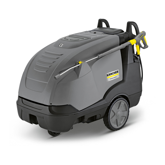
3-фазная модель начального уровня в среднем классе аппаратов высокого давления с подогревом воды: аппарат HDS 8/18-4 M, оснащенный 4-полюсным электродвигателем и предусматривающий экономичный режим eco!efficiency.

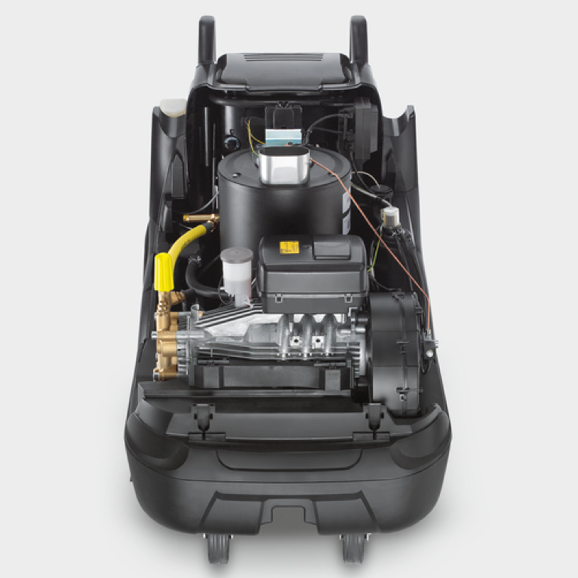
Аппарат высокого давления с подогревом воды HDS 8/18-4 M отличается простым управлением и сервисным обслуживанием, высокой эффективностью мойки, эксплуатационной надежностью и безопасностью для окружающей среды. Поворотный ролик, резиновые шины, эргономичная рукоятка для перемещения, возможность транспортировки погрузчиком и подъема передней части аппарата для фиксации обеспечивают комфортное перемещение. Режим eco!efficiency в сочетании с турбонагнетателем воздуха, функцией дозирования чистящего средства, оптимизированной технологией нагрева, сервисным переключателем для задания жесткости воды и высокопроизводительным насосом гарантирует максимальную эффективность мойки. Специальные приспособления и насадки запатентованной конструкции также вносят свой вклад. Пистолет EASY!Force использует силу отдачи водяной струи для сведения усилия удержания рычага к нулю, а быстродействующие разъемы EASY!Lock в 5 раз ускоряют выполнение различных манипуляций по сравнению с традиционными резьбовыми соединениями – без ущерба для прочности и долговечности. Другие особенности комплектации – функция контроля выхлопных газов, интегрированная система защиты, 3-поршневой осевой насос и жаропрочная облицовка выхлопной трубы. Прочный корпус. Удобный доступ ко всем компонентам, требующим обслуживания.

Особенности и преимущества

Аппарат высокого давления HDS 8/18-4 M: Экономичность

Экономичность

В режиме eco!efficiency аппарат работает в наиболее экономичном диапазоне температур (60 °C) при сохранении максимального расхода воды.
Оптимизация рабочего цикла горелки уменьшает расход топлива на 20 % в сравнении с режимом полной нагрузки.

Аппарат высокого давления HDS 8/18-4 M: Высочайшая эффективность

Высочайшая эффективность

Испытанная высокоэффективная технология нагрева воды.
4-полюсный низкооборотный электродвигатель с длительным сроком службы.

Аппарат высокого давления HDS 8/18-4 M: Эксплуатационная надежность

Эксплуатационная надежность

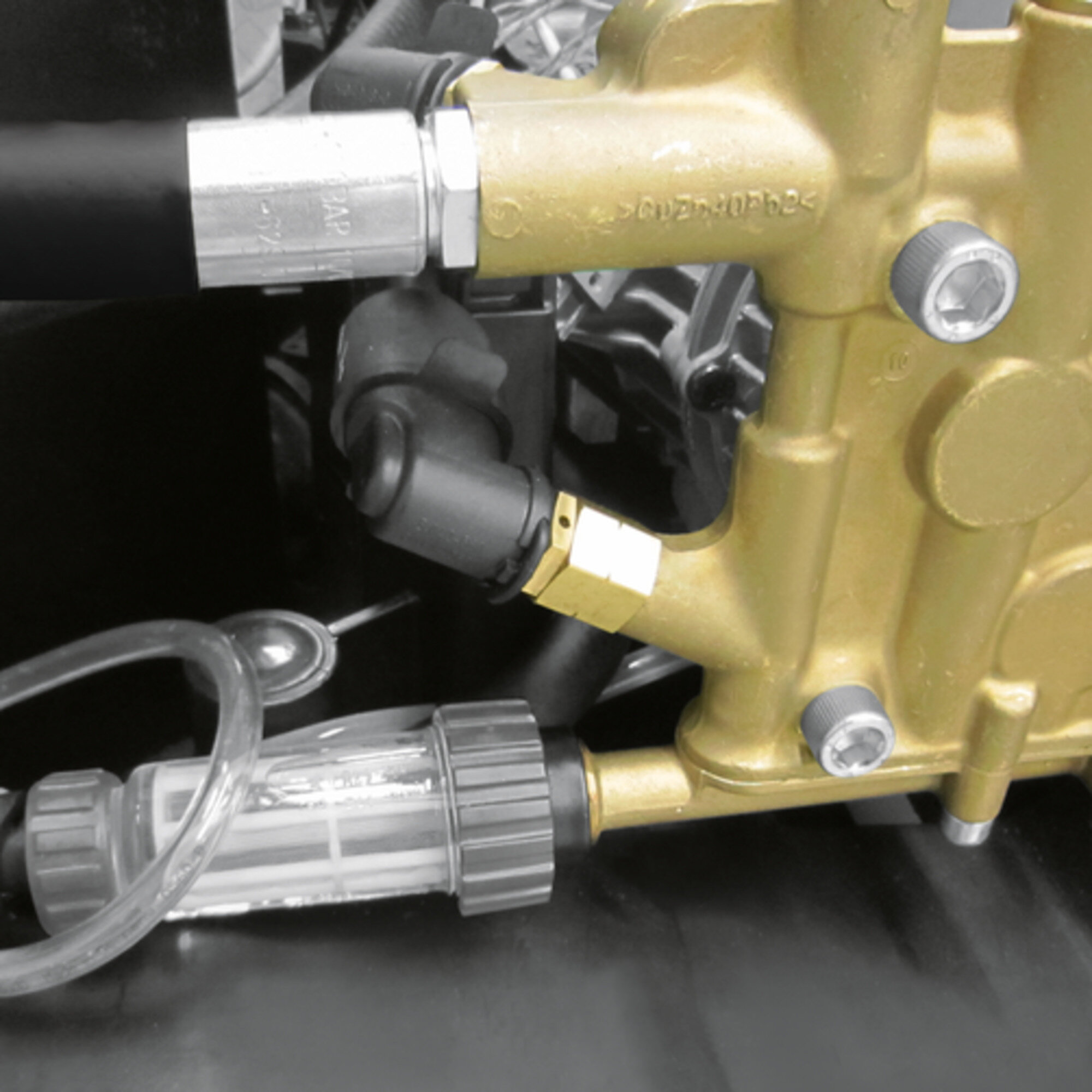
Большой встроенный фильтр тонкой очистки воды надежно защищает насос высокого давления от частиц грязи.
Встроенный термостат отключает приводной двигатель, если температура выхлопных газов превышает 300 °C.
Система эластичного демпфирования SDS компенсирует колебания и перепады давления в системе высокого давления.
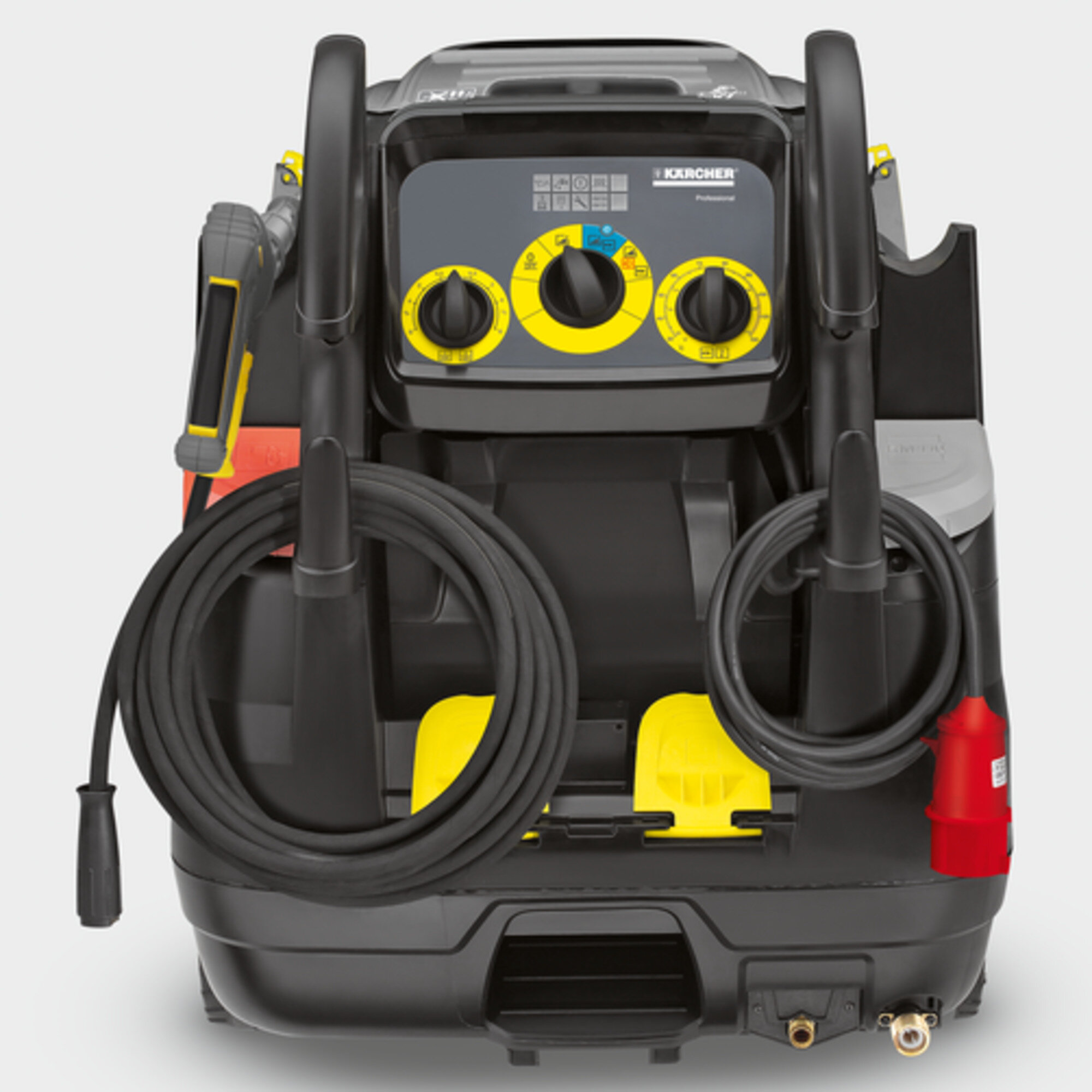
Удобство хранения

  • Возможность надежного размещения защитной экипировки, принадлежностей и чистящих средств.
  • Крюк для хранения сетевого кабеля и шланга высокого давления.

Концепция мобильности

  • Большие задние колеса с резиновыми шинами и переднее поворотное колесико.
  • Специальная опора для подъема передней части аппарата при преодолении порогов.

Для экономии сил и времени: пистолет EASY!Force и быстродействующие разъемы EASY!Lock

  • Возможность продолжительной работы без переутомления благодаря пистолету EASY!Force.
  • Прочные и долговечные разъемы EASY!Lock в 5 раз ускоряют присоединение и отсоединение принадлежностей в сравнении с резьбовыми разъемами.

Спецификации

Технические характеристики

Параметры электросети
(~/В/Гц)
3 / 400 / 50
Производительность
(л/ч)
400 — 800
Рабочее давление
(бар/МПа)
30 — 180 / 3 — 18
Температура (при 12 °C на входе)
(°C)
мин. 80 — макс. 155
Потребляемая мощность
(кВт)
5,5
Макс. расход котельного топлива (газа)
(кг/ч)
5,3
Расход котельного топлива в режиме eco!efficiency
(кг/ч)
4,2
Кабель
(м)
5
Объем бака для котельного топлива
(л)
25
Масса (с принадлежностями)
(кг)
159,3
Масса (с упаковкой)
(кг)
171,3
Размеры (Д × Ш × В)
(мм)
1330 x 750 x 1060

Комплектация и оснащение

  • Функция подачи чистящего средства: баки 20 + 10 л
  • Пистолет: EASY!Force Advanced
  • Шланг высокого давления: 10 м, Long-life
  • Струйная трубка: 1050 мм
  • Мощное сопло
  • ANTI!Twist
  • Заправляемые снаружи бака для чистящего средства, умягчителя и топлива
  • Пульт управления со световыми сигнализаторами
  • Автоматическое отключение
  • Вилка с переключением полярности (3~)
  • Сервисная электроника со светодиодными индикаторами
  • 2 бака для чистящих средств
  • Система защиты от недостатка воды

Аппарат высокого давления HDS 8/18-4 M

Аппарат высокого давления HDS 8/18-4 M

Видео

Области применения
  • Мойка автомобилей
  • Очистка машин и механизмов
  • Уборка в мастерских
  • Уборка на АЗС
  • Чистка фасадов
  • Уборка в бассейнах
  • Очистка производственного оборудования
  • Очистка в процессе производства
  • Уборка на спортивных площадках
Принадлежности

Чистящие средства

Инструкция по эксплуатации / работа с инструментом Аппарат высокого давления с подогревом воды Karcher HDS 8/18-4 C

Находящаяся под высоким давлением струя воды может при неправильном использовании представлять опасность. Запрещается направлять струю воды на людей, животных, включенное электрическое оборудование или на сам моющий аппарат.

Не допускайте попадания сточных вод, содержащих минеральные масла, в почв, водоемы или канализацию. Поэтому мойку моторов и днища автомашин проводить только в приспособленных для этого местах с маслоуловителем.

В качестве среды высокого давления можно использовать только чистую воду. Загрязнения приводят к преждевременному износу устройства или отложению в нем осадка.

Защитные устройства

Перепускной клапан с двумя манометрическими выключателями

При сокращении объема воды в головной части насоса или при помощи регулятора открывается перепускной клапан, и часть воды возвращается к всасывающей стороне насоса.

Если ручной пистолет-распылитель закрывается, и вся вода возвращается к всасывающей стороне насоса, манометрический выключатель на перепускном клапане отключает насос.

При повторном открывании ручного пистолета-распылителя, манометрический выключатель, установленный на головке цилиндра, снова включает насос. Перепускной клапан настроен и опломбирован на заводе. Настройка осуществляется только сервисной службой.

Предохранительный клапан

Предохранительный клапан открывается в случае неисправности перепускного клапана или манометрического выключателя.

Система предохранения от отсутствия воды

Система препятствует включению горелки при отсутствии воды.

Сетка препятствует загрязнению системы и должна регулярно чиститься.

Ограничитель температуры выхлопных газов

Ограничитель отключает аппарат при достижении слишком высокой температуры выхлопных газов.

Начало работы
1. Установка скобы рукоятки


2. Смонтировать ручной пистолет-распылитель, струйную трубку, форсунку и высоконапорный шланг


· Соедините струйную трубку с ручным пистолетом-распылителем.

· Крепко затянуть винтовое соединение струйной трубки.

· Вставьте форсунку высокого давления в накидную гайку.

· Установите и затяните накидную гайку.

3. Залить средство для ухода за системой

· Средство для ухода за системой высокоэффективно препятствует отлтжению кальция на нагревательном змеевике при эксплуатации с водопроводной водой, содержащей кальций. Оно добавляется по капле в приемный канал бака с топливом.

· На заводке дозировка установлена на среднюю жесткость воды.

4. Заправка топливом

· Не эксплуатируйте аппарат с пустым топливным баком. Иначе выйдет из строя топливный насос.

5. Заправка моющим средством

· Не заливайте растворители.

· Избегайте контакта с глазами и кожей.

· Выполняйте указания по технике безопасности и обращению производителя моющего средства.

6. Подключение водоснабжения

· Закрепить шланг подачи воды (минимальная длина 7,5м, минимальный диаметр 3/4″) на комплекте для подвода воды с помощью хомута.

· Подсоединить шланг подачи воды к подключению забора воды аппарата и к источнику воды.

7. Всосать воду из бака

Если Вы желаете использовать воду из внешней емкости, требуется следующее переоборудование

· Вывинтить 2 винта, расположенные на корпусе горелки


· Отвинтить и снять заднюю стенку


· Отсоединить элемент подачи воды от фильтра тонкой очистки.

· Отвинтить фильтр тонкой очистки, расположенный в головной части насоса.

· Снять резервуар со средствами для ухода за системой


· Отвинтить верхний шланг подачи в бак с поплавком.

· Подключить верхний шланг подачи к головной части насоса.

· Вставить заглушку в выходной патрубок клапана-дозатора моющего средства.

· Подключить всасывающий шланг с фильтром к водоснабжению.

· Макс. Высота всасывания 0,5м.

· До того, как насос всосал воду, следует установить регулятор давления/количества на насосе на максимальную величину и закрыть клапан дозатор моющего средства.

8. Подключение к источнику тока

· Неподходящие электрические удлинители могут представлять опасность.

· Всегда следует разматывать удлинители.

· Штекер и соединительный элемент применяемого удлинителя должны быть герметичными.

Управление

Включение прибора

Установите выключатель прибора на нужный режим работы.

Должна гореть контрольная лампочка готовности прибора к работе. Прибор включается на короткое время и отключается, как только достигается рабочее давление. Если во время эксплуатации загорается контрольная лампочка индикации направления вращения, следует немедленно выключить устройство и устранить неисправность.

Регулировка температуры мойки

· Установите выключатель прибора на нужную температуру:

30°С-98°С – мойка горячей водой;

100°С – 150°С – чистка паром;

Режимы работы

Работа с холодной водой

Удаление легких загрязнений и чистовая мойка, напр. :садово-огородного инвентаря, террас, инструментов и пр.

Режим ECO

Используется наиболее экономный температурный режим работы прибора.

Режим работы с горячей водой/паром

Рекомендуются следующие режимы мойки:

· Легкие загрязнения: 30-50°С;

· Загрязнения, содержащие белок, напр. в пищевой промышленности макс.: 60°С;

· Мойка автомобилей: 60-90°С;

· Расконсервация, загрязнения с высоким содержанием жиров 100-110°С;

· Разморозка заполнителей, очистка фасадов: до 140°С.

После эксплуатации с моющим средством:

· Дозирующий клапан моющего средства установить на «0».

· Установите выключатель аппарата на ступень «1» (режим работы с холодной водой).

· Промыть аппарат при открытом клапане пистолета-распылителя минимум 1 минуту.

Выключение

· После эксплуатации с горячей водой или паром устройство в целях охлаждения должно поработать при открытом пистолете в течение не менее двух минут с применением холодной воды.

· Перевести переключатель в положение «0/OFF».

· Закрыть подачу воды.

· Открыть ручной пистолет-распылитель.

· При помощи выключателя прибора на короткое время (ок. 5 секунд) включите насос.

· Вытаскивайте штепсельную вилку из розетки только сухими руками.

· Отсоедините водоснабжение.

· Включить пистолет-распылитель, пока аппарат не освободится от воды.

· Зафиксировать ручной пистолет-распылитель.

Хранение прибора

· Зафиксируйте струйную трубку в креплении крышки прибора.

· Смотайте шланг высокого давления и электрический провод и повесте на держатели.

· Поставте прибор на хранение в защищенное ль мороза место.

Вывод из эксплуатации

При длительном перерыве в эксплуатации или в случае невозможности хранения в месте, защищенном от мороза:

Слить воду.

Отсоедините шланг подачи воды и шланг высокого давления.

Отсоедините подающий провод, отвернув его от дна котла освободив нагревательный змеевик.

Оставьте прибор включенным в течении не более 1 минуты до тех пор, пока насос и трубопроводы не освободятся

Промывка прибора антифризом.

Залейте в бак с поплавком обычный антифриз.

Включить аппарат (без горелки), пока он полностью не прополоскается.

Опорожните бак для моющего средства.

АВД с нагревом воды

Инструкции на аппараты высокого давления с нагревом воды.

  • Аппарат высокого давления с нагревом Karcher HDS 9/20 Classic Kap

    Инструкция по эксплуатации на русском языке

    Скачать
    08.04.2022 12:07
    2,17 МБ
    74

  • Аппарат высокого давления с подогревом воды Karcher HDS 1000 DE Steamer

    Аппарат высокого давления с подогревом воды Karcher HDS 1000 DE Steamer — информация о продукте.

    Скачать
    25.02.2021 18:08
    1,15 МБ
    81

  • Аппарат высокого давления с нагревом Karcher HDS 8/20 G, HDS 8/20 D

    Инструкция по эксплуатации на русском языке

    Скачать
    29.01.2021 15:07
    4,70 МБ
    73

  • Аппарат высокого давления с нагревом HDS 9/50 De Tr1, HDS 13/35 De Tr1, HDS 13/20 De Tr1, HDS 17/20 De Tr1

    Инструкция по эксплуатации на русском языке

    Скачать
    11.10.2019 13:13
    4,76 МБ
    162

  • Аппарат высокого давления с нагревом HDS 6/14-4 C/CX, HDS 8/18-4 C/CX, HDS 9/17-4 C/CX

    Инструкция по эксплуатации на русском языке

    Скачать
    27.05.2019 12:02
    4,43 МБ
    182

  • Аппарат высокого давления с нагревом HDS 6/10 C, HDS 6/12 C, HDS 6/14 C/CX, HDS 7/16 C/CX, HDS 8/17 C/CX

    Инструкция по эксплуатации на русском языке

    Скачать
    22.06.2018 15:42
    4,32 МБ
    209

  • Мобильный водонагреватель Karcher HG 43, HG 64

    Инструкция по эксплуатации на русском языке

    Скачать
    17.04.2018 10:05
    1,50 МБ
    104

  • Аппарат высокого давления с нагревом HDS 9/16-4 ST, HDS 12/14-4 ST EASY!Force, EASY!Lock

    Инструкция по эксплуатации на русском языке

    Скачать
    15.11.2017 16:45
    1,05 МБ
    83

  • Аппарат высокого давления с нагревом HDS 5/12 C EASY!Force, EASY!Lock

    Инструкция по эксплуатации на русском языке

    Скачать
    14.11.2017 17:56
    2,60 МБ
    71

  • Аппарат высокого давления с нагревом HDS 9/16-4 ST Gas, HDS 12/14-4 ST Gas, HDS 12/14-4 ST Gas LPG EASY!Force, EASY!Lock

    Инструкция по эксплуатации на русском языке

    Скачать
    17.01.2019 11:22
    1,28 МБ
    59

Kärcher HDS-E 8/16-4 M Series Service Manual

  1. Manuals
  2. Brands
  3. Kärcher Manuals
  4. Pressure Washer
  5. HDS-E 8/16-4M
  6. Service manual

  • Contents

  • Table of Contents

  • Troubleshooting

  • Bookmarks

Quick Links

HDS-E 8/16-4 M

Service Manual

1

English 5.906-548.0 Rev. 00 (04/12)

loading

Related Manuals for Kärcher HDS-E 8/16-4 M Series

Summary of Contents for Kärcher HDS-E 8/16-4 M Series

  • Page 1
    HDS-E 8/16-4 M Service Manual English 5.906-548.0 Rev. 00 (04/12)
  • Page 2: Table Of Contents

    Preface ……….. . . Safety instructions .

  • Page 3
    5.6.7 Protective conductor connection ……5.7 Detergent……….. . 5.7.1 Detergent Tank .
  • Page 4
    6.1.18 Operating hours of the heater since heater service ….6.1.19 Heater service ……… . 6.1.20 Operating hours of the heater since the startup of the device .
  • Page 5: Preface

    Preface Technical Features Good service work requires extensive and practice- 3.1 General oriented training as well as well-structured training Mobile hot water high pressure cleaner in different materials. performance classes for commercial use. Hence we offer regular basic and advanced training Electrically heated boiler –…

  • Page 6: Boiler

    3.6 Boiler Dosing of system care RM 110/111 with RFID sys- – Heating element output 12/24/36 kW – Quick heating chamber (12 kW model) – Thermal insulation – 3.7 Cleaner 2 detergent tanks – Content of detergent tank 1: 10 l –…

  • Page 7: Parts Of The System

    Parts of the system 4.1 Front view 1 Handle 8 High pressure hose 2 Closing flap for storage compartment 9 High-pressure nozzle (stainless steel) 3 Safety latch of the hand spray gun 10 Bearing wheel 4 Pressure and quantity regulation at the hand spray 11 Mounting location for transport 12 Steering roller with fixed position brake 5 Lever for hand spray gun…

  • Page 8: Rear View

    4.2 Rear view 1 Indicator lamps 10 High pressure connection 2 Power switch 11 Connection for water supply with filter 3 Temperature controller 12 Step depression 4 Storage spray pipe 13 Power supply 5 System care Advance RM 110/RM 111 14 Pouring vent for detergent 1 6 Hose hook 15 Cable hook…

  • Page 9: View From Below

    4.3 View from below 1 Guiding roll with fixed position brake 2 Floor plate 3 Boiler fastening screws 4 Boiler drain screw 5 High pressure line 6 High pressure line bracket 7 Connection for water supply with filter 8 High pressure connection Note The floor plate is intended to reinforce the chassis and as a base plate for the boiler.

  • Page 10: Storage Compartments

    4.4 Storage compartments 4.4.1 Folding compartment 4.4.3 Type plate 1 Bottle holder for cylindrical bottles 1 Nameplate 2 Handle 3 Bottle holder for two RFID system care bottles 4.4.2 Storage compartment 1 Device documentation 2 Storage for rotor nozzle 3 Screw for storage compartment 4 Storage for high-pressure nozzle 5 Screw for operating panel 6 Storage compartment for accessories…

  • Page 11: View Of The Right Side, Appliance Hood Open

    4.5 View of the right side, appliance hood open 1 Boiler 9 Suction hose for detergent 2 Low-pressure hose motor cooling to the boiler 10 High pressure hose between pump and safety valve 3 Fine filter (water) 11 System care hose 4 Electric box, motor 12 Safety valve 5 Oil tank…

  • Page 12: Function

    Function 5.1 Operator console 1 Indicator lamp for pump, red 12 Dossing range of detergent tank 2 2 Indicator lamp «water shortage» red 13 0/OFF 3 ”Ready for use” indicator lamp, green 14 Operating with cold water 4 Indicator lamp — heating, green 15 Power switch 5 Indicator lamp for motor, red 16 Eco! efficiency setting (hot water max.

  • Page 13: Indicator Lamps

    5.1.1 Indicator lamps Indicator Activity Meaning / measure lamp blinks once Oil shortage pump –  Replenish oil. blinks twice Leak in the high pressure system –  Check high pressure system and connections for tightness. blinks thrice Lack of water, the pump is switched off to prevent dry runs after a 2 minute –…

  • Page 14
    Indicator Activity Meaning / measure lamp glow Maintenance due –  Read the necessary maintenance tasks from the control system and per- form them. glow Note: Heater can only operate 5 more hours. System care tank is empty or units on the RFID tag are used up (see «Sys- –…
  • Page 15: Interior Of Operating Panel

    5.2 Interior of operating panel 5.2.1 Open the operating panel Danger Danger of injury by electric shock. Prior to opening the operating panel, all power to the device must be shut off (pull mains plug) and it must be protected from inadvertent startup. 1 Closing flap for storage compartment 2 Screw …

  • Page 16: Operating Panel Open

    5.2.2 Operating panel open 1 Control transformer T1 7 Control electronics 2 Service switch 8 Dosage valve for detergent 3 Control transformer T2 9 Control transformer fuse 4 Transducer 10 Temperature limiter (behind pressure gauge) 5 Power switch 11 Manometer 6 Temperature controller English 5.906-548.0 Rev.

  • Page 17: Control Electronics

    5.2.3 Control electronics 1 Temperature limiter connection/K5 Version numbers of software and hardware The version numbers of the software (SW) and the 2 Connection of level sensor for system care hardware (HW) are indicated on the electronics. 3 Transducer connection The plugs for the PCB connections are designed with 4 Connection, lack of water protection encoding pins and their matching recesses in the…

  • Page 18
    DIP switch Adjust- Function ment by the manu- facturer: No pump trailing * Dosing of system care RM 110/ 111 for water volumes of less than 1,000 l/h Caution Severe reduction of the pump idle time. Do not acti- vate the pump trailing. English 5.906-548.0 Rev.
  • Page 19: Cover

    5.3 Cover 5.3.1 Open the device hood. 5.3.2 Remove the appliance cover 1 Screwdriver 2 Locking 3 Cover  Press the latch down using a screwdriver or a coin and turn it by 90° counter-clockwise.  1 Wire rope Open the device hood. 2 Support …

  • Page 20: Service Switch

    5.4 Service switch 1 Service switch 2 Arrow 3 «OFF» position 4 Service position 5 SET position 5.4.1 Setting up water hardness The water hardness must be set at the site to be able to correctly meter the system care (RM 110/RM 111). …

  • Page 21: System Care Rm 110/Rm 111

    5.5 System care RM 110/RM 111 1 Screw 2 System care bottle 3 Holder for system care bottle with RFID electron- 4 System care bottle seal The dosing of the system care takes place via a re- ciprocating pump. The setting of the service switch determines the dos- ing volume.

  • Page 22: Ventilating The Reciprocating Pump

    5.5.1 Ventilating the reciprocating pump  Note the service switch setting.  Turn on the appliance.  Set the thermostat to 85 °C.  Open the hand spray gun and let the device run.  Rotate the service key into the SET position and hold it there until the pump feeds evenly.

  • Page 23: Boiler

    5.6 Boiler 1 Water inlet 2 Float 3 Cold water tank 4 Water shortage safeguard 5 Warm water tank 6 Overflow 7 Thermal insulation 8 Flange, heating element 9 Heating element (24 kW)* 10 Sensor of the temperature limiter 11 Hot water outlet 12 Temperature sensor 13 Cold water outlet 1 Temerature limiter…

  • Page 24: Remove The Boiler Cover

    5.6.1 Remove the boiler cover 1 Cold water outlet 2 Hot water outlet Unscrew the covering nut. The boiler is divided into a cold and hot water reser- voir by a removable sheet metal part. The water runs into the cold water reservoir via a float valve and is then transferred to the hot water reser- voir.

  • Page 25: Boiler Models

    5.6.2 Boiler models There are three boilers with different heating outputs: 12 kW – 24 kW – 36 kW – The models with 24 kW and 36 kW differ only in their heating element. These models are pictured in the Chapter «Boiler».

  • Page 26: Overflow

    5.6.3 Overflow 5.6.5 Temperature sensor 1 Thermal insulation The control electronics captures the hot water tem- perature via the temperature sensor and switches the 2 Overflow, movable lid in the insulation heating elements off or on as needed. In case of failure of the float valve, the water exits 5.6.6 Temperature controller from the boiler via the overflow.

  • Page 27: Detergent

    5.7 Detergent 5.7.1 Detergent Tank 5.7.2 Filter detergent hose 1 Detergent tank lid 1 Filter 2 Pouring vent for detergent 1 2 Suction hose for detergent 3 Pouring vent for detergent 2 5.7.3 External suction The suctioning of the detergent can also be per- The fill openings of the detergent tanks are located formed outside the appliance.

  • Page 28: High-Pressure Pump

    5.8 High-pressure pump 1 Pressure and volume regulation 2 Oil tank 3 Motor 4 Cooling coil of water cooling 5 Electric box, motor 6 Blower casing of engine air cooling 7 Motor intake 8 Oil level sensor 9 Pump head 10 Solenoid valve for cold water 11 Solenoid valve for warm water English 5.906-548.0 Rev.

  • Page 29
    1 Pressure/ quantity regulation 2 Locking screw for pressure valve 3 Pump head screw 4 Suction jumper screw 5 Suction jumper 6 Solenoid valve for warm water 7 Solenoid valve for cold water 8 Suction hose for detergent 9 Pressure switch OFF 10 Fastener 11 Piston guide screw 12 Pressure switch ON…
  • Page 30
    1 Union joint 2 Disc 3 Suction jumper 1 Union joint 2 Disc 3 Groove for disc English 5.906-548.0 Rev. 00 (04/12)
  • Page 31: Sectional Illustration

    5.8.1 Sectional illustration 1 Cooling coil motor cooling 2 Stator 3 Motor bearing, rear (B bearing) 4 Motor shaft 5 Solenoid (rotor) 6 Motor casing 7 Shaft seal ring, motor shaft 8 Motor bearing, front (A bearing) 9 Swash plate 10 Fastening screw, swash plate 11 Axial ball bearing, swash plate 12 Oil drain screw…

  • Page 32: High Pressure Seal / Low Pressure Seal

    5.8.2 High pressure seal / low pressure seal Seal package high pressure 1 Support ring 2 High pressure seal 3 Back ring 4 Bushing 5 O ring Seal package low pressure 6 Support ring 7 Low pressure seal 8 Back ring 9 Brass support disc Note: Pay attention to installation position of the seals!

  • Page 33: Electric Box 12 Kw

    5.8.3 Electric box 12 kW 1 Contactor heater K2 2 Contactor heater K3 3 Circuit breaker, F1 4 Motor contactor, K1 5 Interference supression capacitor for heater con- tactor 6 Relay lack of water fuse K4 7 Temperature limiter relay K5 8 Ferrite core in the motor supply line 9 Connection pressure switch ON 10 Connection pressure switch OFF…

  • Page 34: Electric Box 24 Kw

    5.8.4 Electric box 24 kW 1 Contactor heater K2 2 Contactor heater K3 3 Circuit breaker, F1 4 Motor contactor, K1 5 Relay lack of water fuse K4 6 Temperature limiter relay K5 7 Interference supression capacitor for heater con- tactor 8 Ferrite core in the motor supply line 9 Connection pressure switch ON…

  • Page 35: Electric Box 36 Kw

    5.8.5 Electric box 36 kW 1 Contactor heater K2 2 Contactor heater K3 3 Circuit breaker, F1 4 Motor contactor, K1 5 Interference supression capacitor for heater con- tactor 6 Relay lack of water fuse K4 7 Temperature limiter relay K5 8 Ferrite core in the motor supply line 9 Connection pressure switch ON 10 Connection pressure switch OFF…

  • Page 36: Hand Spraygun

    5.9 Hand spraygun 1 Safety catch 6 Safety clip 2 Handle bowl 7 Needle bearing 3 Hand lever 8 Hose coupling 4 High pressure hose 9 O ring 5 Hose guide 10 Node piece Note The node piece cannot be repaired and must be re- placed as a complete unit.

  • Page 37: Rotating Regulator

    5.10 Rotating regulator The pressure and volume regulation is performed via a rotating regulator between the gun and the spray lance. There are two ceramic discs within the high pressure channel. One ceramic disc is rigidly connected to the gun con- nection.

  • Page 38: Functional Diagram

    5.11 Functional diagram 1 Water connection 12 Overflow 2 Water supply hose 13 Water shortage safeguard 3 Rough dirt filter 14 Temperature sensor 4 Water fine filter 15 Temperature controller 5 Motor casing with cooling coil 16 Heating element 6 System care bottle 17 Solenoid valve for cold water 7 Reciprocating pump 18 Solenoid valve for warm water…

  • Page 39
    23 Oil tank 24 Pressure and volume regulation 25 Pressure switch «ON» 26 Manometer 27 Rinse hose of the detergent dosing valve 28 Dosage valve for detergent 29 Detergent suction hose with filter 30 Detergent Tank 31 Detergent suction hose with filter 32 Detergent Tank English 5.906-548.0 Rev.
  • Page 40: Pressure And Volume Regulation

    5.12 Pressure and volume regulation 1 Threaded pin, max. pressure setting 16 Pressure holding valve 2 Locknut threaded pin 17 Pressure switch «ON» 3 Semiload spindle 4 Half-load stop sleeve 5 Locknut of semiload stop sleeve 6 Pressure spring 7 Overflow piston 8 High pressure valve (3x) 9 Pump piston (3x) 10 Suction valve (3x)

  • Page 41: Pressure And Quantity Regulation At The Pump

    5.12.1Pressure and quantity regulation at the pump The pressure and volume regulation via the handle on the high pressure pump is used to relieve the mo- tor with mostly partial load operation. Turning the spindle anticlockwise lowers the preten- sion of the pressure spring. This will lift the overflow piston with a lower pressure from the valve seat and part of the flowing volume runs to the suction chamber via the sleeve with the…

  • Page 42: Functional Description Of Pressure Switch

    5.13 Functional description of pressure switch 5.13.1Appliance is switched off 0 Volt 1 High pressure outlet (without pressure) When the appliance is switched off and the gun is open, the pressure is taken from the system and it is 2 Manometer (without pressure) without voltage.

  • Page 43: The Appliance Is Switched On And The Gun Is Open

    5.13.2The appliance is switched on and the gun is open 24 Volt 1 High pressure outlet, working pressure After switching on the appliance and with the gun open, the contactor will be actuated and closes the 2 Manometer, working pressure contacts.

  • Page 44: Gun Is Closed

    5.13.3Gun is closed 24 Volt 1 High pressure outlet, shut-off pressure This will open the overflow valve and the entire flow volume streams into the suction chamber of the 2 Manometer, shut-off pressure pump through the throttle bore. 3 Pressure retaining valve (closed) As soon as the overflow valve opens, the pressure re- 4 Pump stands still taining valve closes and the shut-off pressure is…

  • Page 45: The Gun Is Reopened When The Appliance Is Switched On

    5.13.4The gun is reopened when the appliance is switched on 24 Volt 1 High pressure outlet (without pressure) As soon as the gun is opened, the pressure that is locked in between the pressure retaining valve and 2 Manometer (without pressure) the gun escapes.

  • Page 46: Functional Description Of The Control

    5.14 Functional description of the control 5.14.1Hot water/cold water solenoid valves Pump start First, the respective solenoid valve for cold or warm water will open and 0.3 s later, the high pressure pump starts up. Switching from warm to cold water (or vice-ver- Both solenoid valves are opened for 0.5 s simultaneously.

  • Page 47: Basic Settings And Service Procedures

    Basic settings and service procedures 6.1 Service functions with display 1 Service switch 2 Arrow 3 «OFF» position 4 Service position 5 SET position Key function (will not lock in) 1 Temperature controller 6.1.1 Activating the service function  Turn off the appliance. …

  • Page 48: Changing The Settings

    6.1.4 Overview of the service functions Function 30°C Behaviour of device after 30 minutes of continuous operation. 33°C Behaviour of device after 30 minutes of continuous standby operation. 35°C Behaviour in case of leaks. 38°C Testing the indicator lamps 1 Indicator lamp 0, red 38°C Device with/ without RFID 2 Indicator lamp 1, red…

  • Page 49: Set Up The Switching Off Process

    6.1.5 Set up the switching off process Function adjustment Display Significance 30 °C ON30MIN The device switches off after 30 min- Behaviour of device after 30 min- utes of continuous operation utes of continuous operation. Factory setting The setting will be saved. Switching using SET.

  • Page 50: Rfid Query

    6.1.8 RFID query Function adjustment Display Significance 38 °C RFIDONOFF Device with RFID Information to the control elec- „SET“ tronics whether the device is equipped with supplemental dos- ing via RFID. Device without RFID English 5.906-548.0 Rev. 00 (04/12)

  • Page 51: Check The Temperature Sensor

    6.1.9 Check the temperature sensor Function adjustment Display Significance 40 °C NTCTEST Digit value «0» Display of the water temperature measured by the temperature sensor. The value is shown digit by digit Digit value «1» via the indicator lamps. The display is repeated after a pause.

  • Page 52: Check The Thermostat And The Device Switch

    6.1.10Check the thermostat and the device switch Function adjustment Display Significance 43 °C ENCPROGTEST 30 °C Use this function to test the de- vice switch and the thermostat. In order to start the test: 33 °C  Rotate the service switch to «SET»…

  • Page 53
    Function adjustment Display Significance 43 °C 60 °C 63 °C 67 °C 70 °C 73 °C 77 °C 80 °C 83 °C 85 °C  Adjust thermostat to 43 °C after the test. English 5.906-548.0 Rev. 00 (04/12)
  • Page 54: Check The Service Switch

    Function adjustment Display Significance 43 °C ENCPROGTEST Operating with cold water  Rotate the service switch to «SET» and release it. The light pattern of the indicator lamps now shows the setting of Eco! efficiency setting the device switch. Operating with hot water 6.1.11Check the service switch Function adjustment…

  • Page 55: Sensoren Prüfen

    6.1.12Sensoren prüfen Function adjustment Display Significance 50 °C INPUTTEST Lack of oil fuse closed (float up). Use this function to display the status of the different sensors. Every indicator lamp displays the status of a certain sensor. There- ON pressure switch closed (switch ac- fore, several indicator lamps can tuated).

  • Page 56: Error Memory

    6.1.13Error memory Function adjustment Display Significance 53 °C ERRORS High voltage range Read the error memory. The display consists of 2 steps: 1 Display of the type of fault. 2 Display of the operating time Low voltage range that has elapsed since the fault occurred.

  • Page 57
    53 °C Not used. Not used. RFID electronics defective. End of the fault memory and display of the software version. Example: Software version 1.8 53 °C Clearing the error memory  Set the thermostat to 53°C. „SET“  Rotate the service switch into the «SET» position and hold it there. …
  • Page 58: System Care Consumption

    6.1.14System care consumption Function adjustment Display Significance 57 °C DGTDEZILITER Digit value «0» System care consumption dis- play. The number of used up bottles is displayed. Digit value «1» The value is shown digit by digit via the indicator lamps. The display is repeated after a pause.

  • Page 59: Gun Switches Since The Most Recent Gun Service

    6.1.15Gun switches since the most recent gun service. Function adjustment Display Significance 60 °C SI_PISTOLE Digit value «0» Display of the gun switchings since the most recent gun serv- ice. The value is shown digit by digit Digit value «1» via the indicator lamps.

  • Page 60: Gun Services

    6.1.16Gun services Function adjustment Display Significance 63 °C SCTR_PISTOLE Digit value «0» Number of gun services. The value is shown digit by digit via the indicator lamps. The display is repeated after a Digit value «1» pause. Example: 11 gun services have been per- formed since the device was first used.

  • Page 61: Gun Switches Since Initial Startup

    6.1.17Gun switches since initial startup Function adjustment Display Significance 67 °C TOTALPISTOLE Digit value «0» Display of the gun switchings since device was first started up. The value is shown digit by digit via the indicator lamps. Digit value «1» The display is repeated after a pause.

  • Page 62: Operating Hours Of The Heater Since Heater Service

    6.1.18Operating hours of the heater since heater service Function adjustment Display Significance 70 °C SI_BOILER Digit value «0» Display of the operating time of the heater since the last heater service in hours. The value is shown digit by digit Digit value «1»…

  • Page 63: Heater Service

    6.1.19Heater service Function adjustment Display Significance 73 °C SCTR_BOILER Digit value «0» Display of the heater service. The value is shown digit by digit via the indicator lamps. The display is repeated after a Digit value «1» pause. Example: 4 heater service tasks have been performed since the device was first used.

  • Page 64: Operating Hours Of The Heater Since The Startup Of The Device

    6.1.20Operating hours of the heater since the startup of the device Function adjustment Display Significance 77 °C TOTALBOILER Digit value «0» Display of the operating time of the heater since the initial device startup in hours. The value is shown digit by digit Digit value «1»…

  • Page 65: Operating Hours Of The Pump Since Pump Service

    6.1.21Operating hours of the pump since pump service Function adjustment Display Significance 80 °C SI_PUMPE Digit value «0» Display of the operating time of the pump since the last pump service in hours. The value is shown digit by digit Digit value «1»…

  • Page 66: Pump Services

    6.1.22Pump services Function adjustment Display Significance 83 °C SCTR_PUMPE Digit value «0» Display of the pump services. The value is shown digit by digit via the indicator lamps. The display is repeated after a Digit value «1» pause. Example: 7 pump services have been per- formed since the device was first used.

  • Page 67: Operating Hours Of The Pump Since The Start Up Of The Device

    6.1.23Operating hours of the pump since the start up of the device Function adjustment Display Significance 85 °C TOTALPUMPE Digit value «0» Display of the operating time of the pump since the initial device startup in hours. The value is shown digit by digit Digit value «1»…

  • Page 68: Overview Of A Quick Check Of The Device Status

    6.1.24Overview of a quick check of the device status  Read the fault memory in service mode at 53°C. The operating hours since the last occurrence of – the respective fault are displayed for every type of fault. Date: Part number: Customer: Plant number: Display…

  • Page 69: Maintenance Intervals

    6.1.25Maintenance intervals If the orange service indicator lamp illuminates, serv- ice needs to be performed. Time Maintenance Activity  Every 400 oper- Service boiler Read the operating hours of the boiler (70°C). ating hours  Reading faults (53°C).  Drain water. …

  • Page 70: Adjust The Rotating Regulator On The Pump

    6.2 Adjust the rotating regulator on the pump Note The pressure regulator is used to adjust the opening pressure of the overflow valve. 6.2.1 Setting the maximum working pressure  Fasten the test manometer to the high-pressure connection.  Connect the high-pressure hose and gun to the test manometer.

  • Page 71: Setting The Minimum Working Pressure

    6.2.2 Setting the minimum working pressure  Fasten the test manometer to the high-pressure connection.  Connect the high-pressure hose and gun to the test manometer.  Install thenew high pressure nozzle.  Rotate the rotaring regulator on the gun to the po- sition of highest pressure (direction «+»).

  • Page 72: Remove The Manometer

    6.3 Remove the manometer  Open the operating panel (see «Open operating panel») 1 Screwdriver  1 Fastening clip, left Loosen the fastening clip on the right using a screwdriver. 2 Pressure hose  Pull the manometer out. 3 Washer ring …

  • Page 73: Adjust Safety Valve

    6.4 Adjust safety valve  Install the shut-off valve with thermometer and manometer (special tool) on the high pressure connection. 1 Safety valve 2 Adjustment screw 1 Rotary knob for pressure and volume regulation  Slowly close the shut-off valve and watch the ma- 2 Release opening nometer to see at which pressure the water drips from the outlet of the safety valve.

  • Page 74: Remove The Pump Kit

    6.5 Remove the pump kit  Danger Remove the bottom screws.  Risk of electric shock. Remove the lid. If the appliance is plugged in, there will be voltage  Remove the top screws. supplied to the motor contactor even if the device is …

  • Page 75: Disassemble The High Pressure Pump

    6.6 Disassemble the high pressure pump 6.6.1 Remove the pump head Caution The pump head screws go through the piston guide and are screwed into the motor casing. If necessary, the piston guide must be secured with two fastening screws prior to removing the pump head as the pump oil may leak otherwise.

  • Page 76: Remove The Piston Guide And Replace The Oil Seals

     Unscrew the mounting screws M6x110 evenly against the pressure of the piston springs. Do not tilt the piston guide during this process.  Remove the piston guide and the piston.  Check the piston, springs and O-ring for damage; replace if necessary.

  • Page 77: Low Pressure Seal Packages

    1 Low pressure seal 1 Installation mandrel 2 Support ring 2 Oil seal 3 Bushing 3 Piston guide   Grease the new support ring and the low pressure Install the oil seal into the piston guide free of oil seal and install them.

  • Page 78: Replace High Pressure Seals

    6.6.4 Replace high pressure seals 6.6.5 Remove the suction jumper, replace the seals and the suction valves The suction jumper must be removed to replace the suction valves. Note For the HDS 5/12, the suction jumper is made of plas- tic and does not contain a connection for the deter- gent suction hose.

  • Page 79: Remove The High Pressure Valves

    6.7 Replace the water fine filter. 1 Sleeve with throttle bore 2 Pump head 1 Inlet hose 3 Suction valve 2 Water fine filter 4 Suction valve (removed) 3 Threaded piece  Remove the suction valves using a special pliers. …

  • Page 80: Decalcify Boiler

    6.8 Decalcify boiler. With water with a high calcium content, high heating output and frequent use, there will be increased cal- cification of the heater and the bottom of the boiler even if you use RM 110. Calcification on the heater and split off calcification residue on the bottom of the boiler in a test device with a heating output of 36 kW, approx.

  • Page 81: Remove Boiler

    6.9 Remove boiler Warning Danger of scalding by hot water. After operation with hot water, the device must be operated with openend handgun with cold water for at least two minutes.  Shut off water supply.  Let the device run in cold water operation until the boiler and the lines are empty and the lack of water fuse switches the device off.

  • Page 82: Information For The Assembly

     Unscrew the lack of water protection. 1 Protective conductor connection / earth connec- tion  Disconnect the protective conductor connection.  Disconnect the cable of the heating element in the electric box.  Lift the boiler from the device. 6.9.1 Information for the assembly 1 Solenoid valve for cold water 2 Solenoid valve for warm water…

  • Page 83: Removing The Heating Element

    6.10 Removing the heating element  Remove the boiler (see «Removing boiler»). 6.10.1Information for the assembly  Remove the separator walls from the boiler. 1 Specifications 1 Cable screw connection 2 Date of manufacture: Month/Year 2 Splash guard 3 Nut …

  • Page 84: Remove The Rotary Switch

    6.11 Remove the rotary switch Danger 6.11.2Removing the thermostat Adhere to the electrical safety instructions when The thermostat is removed in the same fashion as the working on the electrical system of the appliance. device switch. Disconnect the appliance from power, secure against inadvertent connection and ensure that no voltage is flowing to the appliance.

  • Page 85: Troubleshooting

    Troubleshooting  Danger Open the water supply again. Risk of injury by inadvertent startup of appliance and If the pump still is not sucking in any detergent, it electrical shock. could be because of the following reasons: Adhere to the electrical safety instructions when Filter in the detergent suck hose dirty –…

  • Page 86: Technical Specifications

    Technical specifications Please observe the most current and extended tech- nical specifications in DISIS. HDS-E 8/16-4M HDS-E 8/16-4M HDS-E 8/16-4M 12kW 24kW 36kW Main Supply Voltage Current type 3~ 50 Connected load 17,5 29,5 41,5 Protection (slow) 17,5 Water connection Max.

  • Page 87: Special Tools

    Special tools Electric measuring appliance 6.803-022.0 Removal pliers, pressure/suction 4.901-062.0 valves and water sieves Shut-off valve with thermometer 2.901-030.0 Installation mandrel with sleeve for 2.901-033.0 high pressure/oil seals (D = 18 mm) Ohne Abbildung Installation screws, piston guidance 7.304-467.0 Adapter system 2000, M22x1.5 with 4.401-072.0 (2x M6x110) extended acorn nut.

  • Page 88: Torques

    10 Torques Tightening torques in Nm Pump set Pump head 50-60 Piston guide Valve screw 40-45 Suction jumper 20-22 Pressure switch 30-35 Connection of detergent hose 30-35 Oil tank 3,5-4 Motor Swash plate 12-15 Oil drain screw 20-25 B bearing 9-10 Ventilator casing/motor 2-2,5…

  • Page 89: Circuit Diagrams

    11 Circuit diagrams Note Please observe the most current circuit diagrams in DISIS. English 5.906-548.0 Rev. 00 (04/12)

  • Page 90
    English 5.906-548.0 Rev. 00 (04/12)
  • Page 91
    English 5.906-548.0 Rev. 00 (04/12)
  • Page 92: Cut-Out Masks To Place On The Operating Panel

    12 Cut-out masks to place on the operating panel English 5.906-548.0 Rev. 00 (04/12)

Понравилась статья? Поделить с друзьями:
  • Дизверт таблетки инструкция по применению взрослым
  • Дизал сироп от аллергии инструкция
  • Дизал от аллергии инструкция по применению цена таблетки взрослым
  • Дизал от аллергии инструкция отзывы
  • Дизал от аллергии инструкция для детей