- Manuals
- Brands
- SHOWTEC Manuals
- Controller
- showdesigner 512
- User manual
-
Contents
-
Table of Contents
-
Troubleshooting
-
Bookmarks
Quick Links
Showdesigner 512
ORDERCODE 50721
Related Manuals for SHOWTEC showdesigner 512
Summary of Contents for SHOWTEC showdesigner 512
-
Page 1
Showdesigner 512 ORDERCODE 50721… -
Page 2
For more information: iwant@showtec.info You can get some of the best quality, best priced products on the market from Showtec. So next time, turn to Showtec for more great lighting equipment. Always get the best — with Showtec ! Thank you! -
Page 3: Table Of Contents
Showtec Showtec Showdesigner 512 Product Guide ™ Warning …………………………….2 Safety-instructions …………………………2 Operating Determinations ……………………….3 Return Procedure …………………………4 Claims …………………………….4 Description …………………………….5 Features …………………………….5 Overview ……………………………..5 Controller front ……………………………6 — Fixture selection buttons ……………………..6 — Sliders and LED indicators ………………………6 — Function buttons ……………………….6 — Storage Area of Scene, Chase and Chase group …………….8…
-
Page 4: Warning
Save the carton and all packing materials. In the event that a fixture must be returned to the factory, it is important that the fixture be returned in the original factory box and packing. Your shipment includes: • Showtec Showdesigner 512 • IEC powercable • User manual…
-
Page 5: Operating Determinations
If your Showtec device fails to work properly, discontinue use immediately. Pack the unit securely (preferably in the original packing material), and return it to your Showtec dealer for service.
-
Page 6: Return Procedure
Return Procedure Returned merchandise must be sent prepaid and in the original packing, call tags will not be issued. Package must be clearly labeled with a Return Authorization Number (RMA number). Products returned without an RMA number will be refused. Highlite will not accept the returned goods or any responsibility. Call Highlite 0031-455667723 or mail aftersales@highlite.nl and request an RMA prior to shipping the fixture.
-
Page 7: Description
Description of the device Features Showdesigner is a light controller from Showtec and features: • 512 DMX control channels, compatible with DMX512/ 1990 standard. • Control up to 32 fixtures, each with up to 16 channels. • 16 Sliders on the frontpanel for easy and fast control of all the channels in the fixture.
-
Page 8: Controller Front
Controller Front 1. Fixture selection buttons Page 1 and Page 2 each contain 16 fixtures which can be selected by the 16 buttons for fixture selection in combination with the Page 1 (4.6) and Page 2 (4.6) buttons. 16 DMX channels can be assigned to each fixture.
-
Page 9
3.2 Clear/Exit Clear: The function of this button varies with the state of the device. ● Pressing the button clears the manual entry for the corresponding fader ● Pressing and holding the button for 3 seconds clears all manual entries for chases, faders, scenes and groups. -
Page 10: Storage Area Of Scene, Chase And Chase Group
3.15 E/XY: Use this button to switch between either speed/slope or pan/tilt function for the jog wheels. Speed/slope mode: LED is off. The speed/ slope for a chase group can only be adjusted by X/speed (5). Pan/ tilt mode: LED is on. 3.16 </SETX, >/SETY: Use this buttons to change the direction of a running chase.
-
Page 11: Master Control
5. Jog Wheels 5.1 X/Speed, Y/Slope: Use to control the pan/ tilt of the fixtures (the pan/ tilt channels should be assigned to the jog wheels) and speed/ slope adjustment of chase and chase group. 6. Master control 6.1 Master control buttons The master control buttons Dimmer 1, Dimmer 2, Dimmer 3 are respectively used to enable/disable and setup the three master controls.
-
Page 12: Installation
Installation Remove all packing materials from the Showdesigner 512. Check that all foam and plastic padding is removed. Screw the equipment into a 19″ rack. Connect all cables. Always disconnect from electric mains power supply before cleaning or servicing. Damages caused by non-observance are not subject to warranty. Set Up and Operation Before plugging the unit in, always make sure that the power supply matches the product specification voltage.
-
Page 13: Clear
Clearing scenes, chases or group pages Clearing a entire group, scene or chase page is usefull to get a clean output when programming the console. 1. Select the scene, chase or group page you want to clear. Note: All three pages from the chase or scene are released with this action so you don’t have to clear each chase or scene page separately.
-
Page 14: Run A Chase
6. Adjust your settings by moving the faders. Note: If a fader does not respond, move the fader to the zero position and try again. 7.Adjust the Speed and Slope using the X/Speed (5.1) and Y/Slope (5.1) jog wheels. 8. Press the Add (3.6) button to save the step. The console will repeat the step number with 1. Repeat 5 to 8 as many times you like up to a maximum of 200 steps.
-
Page 15: Create A Chase Group
Tempo of the chase: You can run the Showdesigner in either Auto mode or in music mode by respectively pressing the Auto (3.13) button or the Music (3.12) button. Auto mode In automode you can adjust the speed by tapping the Tap (3.17) button. In auto mode you can adjust the speed and slope of each chase separately while turning the X/Speed (5) and Y/Slope jog wheels (5).
-
Page 16: Setup Of Slope Channels
Tilt (Y) movement 1. Press the Program (3.5) button to enter program mode. The display will show: Program mode. 2. Press the /set Y (3.15) button the LED will blink. 3. Select the fixture(s) you want to control by pressing the Fixture selection buttons (1). The display will show: Program Mode Y Channel 4.
-
Page 17: Maintenance
7. Check power from the wall, all cables, the fuse, the settings (return to default), etc. 8. If all of the above appears to be O.K., plug the unit in again. 9. If nothing happens after 30 seconds, unplug the device. 10. Return the device to your Showtec dealer.
-
Page 18: Product Specifications
Product Specification Model: Showtec Showdesigner 512 Power input : AC 100V-240V, 50/60Hz, 30W. DMX-Output: 3-pin female XLR MIDI-Signal: 5-pin standard interface Audio Input: 100 mV~1Vpp. Fuse: F1.5A 250V 5×20 mm Dimensions : 480 x 290 x 95 mm (LxWxH) Weight : 5,1 kg Design and product specifications are subject to change without prior notice.
-
Page 19
2011 Dap Audio.
Комплектация архитектурных светильников MH50.
В комплекте со светодиодной архитектурной подсветкой MH50 поставляется шнур питания,
Пульт управления ДМХ Мастер и сигнальный провод длиной 50 метров с разъемами
XLR для передачи сигналов управления от пульта к первому световому прибору.
Сигнальные кабели для передачи сигнала от первого прибора к каждому последующему находятся в коробке с приборами, по одному кабелю в коробке.
Светильник MH50 состоит из двух секций.
Каждая секция имеет 5 каналов управления по протоколу ДМХ-512.
Итого весь прибор управляется по десяти каналам.
Описание каналов управления MH50.
Первая секция:
Вторая секция:
Установка стартового адреса DMX.
Пример установки адресации.
На каждом приборе есть кнопки для установки стартового адреса ДМХ.
Стартовый адрес означает, что если вы установите первый прибор адресом 001
То он будет управляться по первым десяти каналам (из 192 возможных),
т.е. от первого по десятый канал.
Следующий прибор нужно установить со сдвигом на один, т.е. одиннадцатым и далее плюс десять к каждому последнему адресу.
Для удобства программирования, в случае работы с этим пультом,
лучше адресовать приборы через 16 адресов.
Т.е. первый прибор имеет адрес 001, второй адресом 017, третий адресом 033 и так далее.
Таким образом, нажимая, при программировании на кнопку Scanner 1 вы обращаетесь к первому прибору и нажимая, на клавиши Scanner 2 вы обращаетесь ко второму прибору и так далее.
Такая адресация необходима в том случае, если все секции всех приборов будут управляться раздельно, т.е. самостоятельный выбор любого цвета в любом приборе.
Если нужно чтобы все или группы приборов управлялись синхронно, можно установить их одинаковыми адресами.
Подключение приборов к пульту.
Включите питание всех приборов.
Установите адреса приборов MH50 — 1, 17, 33, 49, 65, 81, 97, 113, 129, 145, 161, 177.
Соедините пульт ДМХ Мастер с первым прибором MH50 сигнальным шнуром.
Соедините первый прибор со вторым прибором перемычкой (в комплекте) и так далее все приборы соединить последовательно.
Включите блок питания пульта ДМХ Мастер или DL100 в сеть 220 вольт.
Программирование.
Общие принципы программирования с помощью пульта DL100 или DMX Operator:
Пульт имеет два режима работы.
1) Программирование-Запись и изменение сцен и программ (Только режим «Program»).
2) Воспроизведение сцен и программ.
А) Воспроизведение в «Ручном режиме»
Б) Воспроизведение в «Автоматическом режиме» с выбором скорости выполнения программы.
режим «Program»:
Сначала вы записываете в банк сцен (Восемь кнопок вверху пульта с надписью «Scenes») статичные сцены с выбранным цветом.
В память пульта можно записать 240 сцен (30 банков по 8 сцен). Банки (ячейки памяти) выбираются кнопкой около дисплея с надписью Bank.
Затем при программировании «Чейзов» = Программ, сообщаете
Программе, какие сцены, из какого банка она должна воспроизвести.
Программа будет воспроизводить записанные в нее сцены из банков сцен.
Скорость работы программы изменяется в процессе воспроизведения с помощью
переменного резистора Speed слева под дисплеем.
Скорость перехода от сцены к сцене регулируется резистором Fade Time
Комбинируя, положение фейдеров Speed и Fade time вы можете подобрать
нужный вам ритм переключения приборов в процессе воспроизведения программы.
Программирование сцен:
После включения блока питания пульта, пульт управления находится в ручном режиме.
Для входа в режим программирования нажмите и удерживайте нажатой три секунды клавишу Program.
После этого должен загореться светодиод на дисплее напротив надписи Program.
Пульт готов к программированию статичных световых картин.
Проследите, чтобы не горел светодиод напротив надписи blackout — если светодиод горит, это значит, что на выходе пульта нет управляющего сигнала (иногда нужно чтобы выключить приборы не прерывая работу программы).
А) Затем клавишами под надписью Scanners выберите № прибора который собираетесь программировать, в вашем случае №1. (последовательность программирования может быть любой т.е. можно взять сначала прибор №3 и т.п.).
Теперь 8 переменных резисторов на панели управления будут управлять функциями световых приборов (приборами любого типа).
В каждом конкретном приборе, если это не светодиодные MH50, эти переменные резисторы будут управлять тем, что заложено
в прибор производителем.
Итак, с помощью резисторов (движков, слайдеров, фейдеров) управления устанавливаете требуемый цвет, яркость и если надо, мигание.
Первая секция MH50:
Вторая секция:
(ВНИМАНИЕ! Для того чтобы перейти на вторую страницу и управлять девятым и десятым каналом, надо нажать на кнопку Page Select и перейти на вторую страницу)
Вы установили нужный цвет первого прибора!
Если Вы пишете программу, в которой первая сцена это — один прибор светит а остальные не светят, то надо сохранить эту сцену, нажав на кнопку Midi/ADD и затем на кнопку Scene 1 — т.е. сначала сообщаете пульту, что вы хотите что-то сохранить, затем указываете в какой банк (по умолчанию Bank №1 пока на запишете восемь сцен), и в какую сцену, указав номер № сцены (Жмите на клавишу с номером сцены). Пульт мигнет индикатором три раза, это значит, что сцена записана.
Б) Затем снимите обращение, к первому прибору, нажав на клавишу с надписью Scanner 1 выбрать клавишами Scanners прибор №2 (!!не забудьте снять обращение к первому прибору!!).
Также как и в первом случае установить нужный цвет, яркость и если надо, мигание.
В) Затем снять обращение ко второму прибору (и не забудьте снять обращение к прибору №2), выбрать клавишами Scanners прибор №3 и выбрать нужный цвет, яркость и если нужно, мигание.
Г) Затем выбрать прибор №4 (и не забудьте снять обращение к прибору №3).
И так далее все приборы.
Вы установили первую световую картину (Сцену) и для записи её в память пульта надо нажать клавишу MidiADD
и выбрать № сцены цифровыми клавишами (расположены горизонтально в верхней части пульта под надписью SCENES-для начала нажать №1.
Пульт мигнет всеми индикаторами три раза, значит, сцена записана в банк сцен под номером один.
Обычно по умолчанию первые 8 сцен записывается в первый банк.
Всего пульт имеет 30 банков по 8 сцен.
Когда заполните первый банк (первые 8 сцен), переключитесь на 2 банк с помощью клавиш Bank+ или Bank-, там их две и они листают банки вверхвниз. И так далее.
Номера банков сцен отображаются на дисплее (правая цифра).
Для записи других световых сцен надо повторить шаги А-Б-В-Г — и так далее.
Внимание! Повторение! Для сохранения статичной сцены, сначала нажмите клавишу добавить MidiADD и затем номер сцены для сохранения.
Всего в пульте можно записать 240 сценкартин. Имеется 30 банковячеек памяти по 8 сценкартин в каждой ячейке.
Банк сцен не обязательно должен быть заполнен до конца.
Пишете нужное вам количество сцен!
Структура банков сцен пульта.
              Сцены с 1 по 8
Банк №1  1  2 3 4 5 6 7 8
Банк №2  1  2 3 4 5 6 7 8
Банк №3  1  2 3 4 5 6 7 8
Банк №4  1  2 3 4 5 6 7 8
Банк №5  1  2 3 4 5 6 7 8
Банк №6  1  2 3 4 5 6 7 8

------------------------------------------------
--      1  2 3 4 5 6 7 8
--      1  2 3 4 5 6 7 8
--      1  2 3 4 5 6 7 8
Банк №30 1  2 3 4 5 6 7 8
Стирание программ.
Внимание! Перед записью программ, лучше стереть старые программы, т.к. если старые программы были длиннее чем новые, то лишние сцены не сотрутся при записи новой программы.
Стереть программы можно в режиме программирования (Program).
Войдите в режим «PROGRAM» нажать и удерживать нажатой три секунды кнопку «Program».
Затем нажать и держать нажатой номер программы которую вы хотите стереть одновременно нажимая кнопку с надписью «Auto / Dell».
После этого индикатор пульта мигнет три раза. Это говорит о том, что программа стерта.
Проверить легко. Выйдите в режим программирования, нажимая три секунды кнопку «Program».
После этого пульт выйдет из режима программирования. Автоматически загорится индикатор напротив надписи «Black Out».
Нажмите на кнопку «Black Out» чтобы открыть выход пульта, затем выберите программу и нажмите кнопку «Auto / Dell». Если вы корректно стерли программу, ничего не будет происходить.
**********************************************************************************************
Стирая программу, вы никак не влияете на память сцен и всегда можете
оперативно записать любую программу, используя банк сцен.
***********************************************************************************************
Режим «Black Out»
Внимание! При каждом выходе из режима программирования выходной сигнал пульта автоматически блокируется и загорается светодиод напротив надписи «Black Out» около дисплея.
Чтобы снять блокировку, нажмите на кнопку «Black Out» и светодиод напротив надписи «Black Out» погаснет и это значит, выходной сигнал пульта поступает в приборы.
Режим «Black Out» нужен для того, чтобы можно было остановить работу приборов на время, не останавливая работу программы.
Запись программ.
Световые сценыкартины можно разнообразить и сделать более динамичными или медленными, если записать их в Программы и воспроизводить в автоматическом режиме.
Программа это набор сцен записанных в нее в определённой последовательности.
Сцены в программу можно записывать из любого банка сцен.
Можно повторять одну сцену некоторое количество раз и затем перейти к другой.
Необходимо помнить, что в одну программу можно записать не более 240 сцен.
Многократно записывая одну и ту же сцену в разные шаги программы, можно установить время смены световой картины достаточно большим (актуально для подсветки фасадов зданий и декоративного освещения внутри помещений).
Начало написания программ.
Не выходя из режима программирования для записи программы, выберите
№ программы, которую собираетесь писать клавишами от Chase 1 до Chase 6.
Например, выберем Chase 1. На индикаторы отобразится (появится) номер «Чейза». Затем набираем в Чейз = Программа нужные вам сцены из банка сцен.
Первая сцена (добавление в программу):
А)) Для этого нажмите клавишу номера сцены, и прибор ее немедленно покажет.
Если сцена вас устраивает, нажмите клавишу
для записи сцены в программу.
Если не устраивает, читайте пункт «Просмотр, редактирование сцен и Изменение сцен в банке памяти»
Вторая сцена (добавление в программу):
Б)) Для этого нажмите клавишу номера сцены, и прибор ее немедленно покажет.
Если сцена вас устраивает, например сцена номер №2 из первого банка, нажмите клавишу MidiADD для записи сцены в программу.
Если не устраивает, читайте пункт «Просмотр, редактирование сцен и Изменение сцен в банке памяти»
Остальные сцены:
Повторить пункт А)) и Б))
далее номер сцены затем добавить (Midi/Add), № сцены затем добавить столько раз, сколько вам надо.
Когда закончится первый банк сцен, можно перейти во второй банк, нажав на кнопку Bank+ или Bank-, там их две, и они листают банки вверхвниз.
В программе сцена называется «Шаг» или «Step».
Шагов в одном ЧейзеПрограмме может быть не более 240.
В таком количестве шагов нет необходимости и на практике чем проще программа,
тем лучше она смотрится.
После добавления всех необходимых сцен в программу процесс программирования
Надо завершить выходом из режима программирования.
Для выхода из режима программирования нажать и удерживать 3 сек. Клавишу Program.
Пульт имеет два режима работы.
1> Программирование-Запись и изменение сцен и программ (режим «Program»).
2> Просмотр сцен и Воспроизведение программ (режим «Manual»).
А) Воспроизведение в «Ручном» режиме
Б) Воспроизведение Сцен и Программ в «Автоматическом режиме» с выбором скорости выполнения.
2> А) «Ручной режим» Воспроизведение Сцен.
После включения пульта в сеть он автоматически переходит в ручной режим.
Выберите банк ячейку клавишами Bank и нажмите № сцены, которую хотите увидеть.
Затем выберите следующую сцену и так далее.
Редактирование сцен только в режиме Program> !!!.
Войти режим Program выбрать сцену клавишами SCENES.
Для редактирования ранее созданных сцен надо выбрать прибор клавишами Scaners
Изменять положение луча, цвет и др. у выбранного прибора. Затем просто сохраните
изменения под тем же номером нажимая на Кл. MidiADD и затем на № сцены
которую вы вызывали.
Для воспроизведения из выбранного банка сценкартин в автоматическом режиме
нажмите клавишу AutoDel для активации авто режима.
Выберите номер ячейки памяти сцен клавишами Bank и сцены начнут автоматически воспроизводиться со скоростью паузами, на которые настроены переменные резисторы Speed (скорость программы) и Fade Time (время удержания сцены).
Выбрать скорость воспроизведения сцен двумя способами:
1) С помощью переменных резисторов Speed и Fade Time (один из них скорость смены картин, а другой время стояния на месте = пауза).
2) Если три раза с одинаковыми интервалами нажать на клавишу Tap Sync, то эти интервалы будут приняты пультом за скорость воспроизведения.
Интервалы между нажатиями могут соответствовать ритму музыкального сопровождения.
Клавиша Tap Sync имеет приоритет над ползунковыми переменными резисторами скорости и паузы!
Для выхода из Автоматического режима надо нажать клавишу Auto Del еще раз (Если это вам сейчас необходимо).
<Авто Триггер и Аудио Триггер> Автомат и от Звука.
Автоматический режим работы программы от внутреннего тактового генератора
Войдите в автоматический режим, нажав на кнопку Auto/Dell
Загорится индикатор возле дисплея напротив надписи Auto Trigger.
Выберите нужную программу с помощью блока программных клавиш Chase №.
Например, Chase №1. Программа будет воспроизводиться с выбранной скоростью.
Выберите скорость воспроизведения вручную с помощью переменных резисторов Speed и Fade Time или с помощью клавиши Tap Sync.
Резисторы Speed и Fade Time для максимально быстрого воспроизведения, установите Speed = 0.1 sec, Fade Time = 0
В пульте можно записать только шесть программ.
Все программы могут работать или по одной или последовательно в любом выбранном порядке.
Это значит, если вы выбрали первую программу, то работает только первая программа. Если вы перед входом в режим Auto или после входа в режим «Auto», выбрали подряд две программы, то обе программы будут воспроизводиться одна после другой в закольцованном режиме.
Если выбрать все шесть программ, то все шесть программ будут отрабатываться последовательно.
Чтобы исключить программу из списка воспроизведения, надо еще раз нажать на кнопку с номером той программы, которую вы хотите исключить.
В пульте имеется встроенный микрофон.
Для перехода к режиму музыкальной активации программы, выберите номер программы кнопками Chase №.
То что вы уже выбрали программу отобразится на дисплее — загорится номер программы напротив надписи Chase.
Нажмите один раз кнопку Music/Bank Copy — на индикаторе появится соответствующий значок.
Теперь если зазвучит музыка, сцены программы будут переключаться автоматически на максимальный уровень сигнала от микрофона.
Максимальный уровень обычно имеют басовые ноты в музыкальном сопровождении.
Если вам надо изменить сцены в каком либо банке памяти, войдите в режим программирования — нажать и держать три секунды кнопку «Program». Затем выберите банк сцен кнопками Bank.
По умолчанию выбран банк №1. Затем выберите сцену. Можете просмотреть все сцены во всех банках и записать на бумаге те номера сцен, которые вы хотите изменить.
Можете сразу во время просмотра, увидев неправильную сцену, изменить ее.
Для этого последовательно обратитесь к приборам, которые участвуют в этой сцене с помощью кнопок Scanner и перемещая движки переменных резисторов, установите нужный цвет и другие функции, затем сохраните измененную сцену под старым номером, нажав на кнопку Midi / ADD.
Т.е. сначала вход в «Program» затем просмотр сцены, нажимая кнопку с номером сцены, затем изменение, затем сохранить, нажав «Midi / Add».
1) Если после входа в режим Авто и выбора программы, программа не воспроизводится, значит или она не записана или стерта или скорость воспроизведения установлена очень маленькая.
2) Также проверьте, не нажата ли кнопка Black Out (горит светодиод напротив надписи Black Out возле дисплея).
**********************************************************************************************
Стирая программу, вы никак не влияете на память сцен и всегда можете
оперативно записать любую программу, используя банк сцен.
***********************************************************************************************

Congratulations!
You have bought a great, innovative product from Showtec.
The Showtec Showdesigner 512 brings excitement to any venue. Whether you want simple plug-&-play action or a sophisticated DMX show, this product provides the effect you need.
You can rely on Showtec, for more excellent lighting products.
We design and manufacture professional light equipment for the entertainment industry.
New products are being launched regularly. We work hard to keep you, our customer, satisfied. For more information: iwant@showtec.info
You can get some of the best quality, best priced products on the market from Showtec. So next time, turn to Showtec for more great lighting equipment.
Always get the best — with Showtec !
Thank you!

|
Showtec |
||
|
Showtec Showdesigner 512™ Product Guide |
||
|
Warning..…………………………………………………………………………..……………………………………………………….. |
2 |
|
|
Safety-instructions…………………………………………………………………………………….…………………… |
2 |
|
|
Operating Determinations………………………………………………………………………………………………. |
3 |
|
|
Description..……………………………………………………………………………….……………………………….……………… |
4 |
|
|
Features…….……………………………………………………………………………………….……….……………… |
4 |
|
|
Overview…………………………………………………………………………………………………………………… |
4 |
|
|
Controller front………………………………………………………………………………………………………………………………… |
5 |
|
|
— Fixture selection buttons……….. |
…………………………………………………………………………………………… |
5 |
|
— Sliders and LED indicators…………………………………………………….. |
………..…………………………………….. |
5 |
|
— Function buttons…………………………………………………………………………………………………………………… |
5 |
|
|
— Storage Area of Scene, Chase and Chase group…………………………………………………………………… |
7 |
|
|
— Jog wheels……………………………………………………………………………………………………………………………. |
7 |
|
|
— Master control…………………………………………………………………………………… |
………….……………………… |
7 |
|
Controller backside…………………………………………………………………………………………………………………………. |
8 |
|
|
Installation………………………………………… |
………………………….…………………………………………..………………… |
9 |
|
Installation…………………………………………….………………………………………..……………………………………… |
9 |
|
|
Set Up and Operation…………………………. |
………………………………..……..…………………………….………………… |
9 |
|
Operation …………………………………………………………………………..……….……………………………………….. |
9 |
|
|
— Power on…………………………………………….. |
…………………………………………………………………………….. |
9 |
|
— Fixture selection……………………………………………………………….…………………………………………………… |
9 |
|
|
— Manual control………………. |
……………………………………………………………………..……………………………… |
9 |
|
— Clear………………………………………………………………………………………………………………………………………. |
9 |
|
|
— Create a scene……………………………………………………………………………..…………………………………….. |
10 |
|
|
— Run a scene…………………………………………………………………………………………………………………………… |
10 |
|
|
— Create a chase……………………………………………………………………………………………………………………… |
11 |
|
|
— Run a chase…………………………………………………………………………………………………………………………… |
12 |
|
|
— Create a chase group…………………………………………………………………………………. |
..…………………….. |
13 |
|
— Run a chase group ………………………………………………………………………………………………………………… |
13 |
|
|
— Jog wheel assignment……………………………………………………………………………………………………………. |
14 |
|
|
— Using the jog wheels……………………………………………………………………………………………………………….. |
14 |
|
|
— Setup of slope channels………………………………………………………………………………………………………….. |
14 |
|
|
— Delete…………………………………………………………………………. |
….…………………………………………………….. |
14 |
|
— Create a master control…………………………………………………………………………………………………………. |
15 |
|
|
Maintenance……………………………………………………………….. |
…….………..………….…….…………………………….. |
16 |
|
Troubleshooting………………………………………………………………….………………….………………….…………………. |
16 |
|
|
Product Specifications…………………………………………………. |
…….……………….…….…………………………………. |
17 |
1

WARNING
CAUTION!
Keep this device away from rain and moisture!
FOR YOUR OWN SAFETY, PLEASE READ THIS USER MANUAL CAREFULLY
BEFORE YOUR INITIAL START-UP!
SAFETY INSTRUCTIONS
Every person involved with the installation, operation and maintenance of this device has to:
—be qualified
—follow the instructions of this manual
CAUTION! Be careful with your operations. With a dangerous voltage you can suffer
a dangerous electric shock when touching the wires!
Before your initial start-up, please make sure that there is no damage caused by transportation. Should there be any, consult your dealer and do not use the device.
To maintain perfect condition and to ensure a safe operation, it is absolutely necessary for the user to follow the safety instructions and warning notes written in this manual.
Please consider that damages caused by manual modifications to the device are not subject to warranty.
This device contains no user-serviceable parts. Refer servicing to qualified technicians only.
IMPORTANT:
The manufacturer will not accept liability for any resulting damages caused by the nonobservance of this manual or any unauthorized modification to the device.
Never let the power-cord come into contact with other cables! Handle the power-cord and all connections with the mains with particular caution!
Never remove warning or informative labels from the unit. Do not open the device and do not modify the device. Do not insert objects into air vents.
Do not connect this device to a dimmerpack.
Do not switch the device on and off in short intervals, as this would reduce the device’s life.
Only use device indoor, avoid contact with water or other liquids. Avoid flames and do not put close to flammable liquids or gases.
Always disconnect power from the mains, when device is not used or before cleaning! Only handle the power-cord by the plug. Never pull out the plug by tugging the power-cord. Make sure that the device is not exposed to extreme heat, moisture or dust.
Make sure that the available voltage is not higher than stated on the rear panel.
Make sure that the power-cord is never crimped or damaged. Check the device and the powercord from time to time.
If device is dropped or struck, disconnect mains power supply immediately. Have a qualified engineer inspect for safety before operating.
If the device has been exposed to drastic temperature fluctuation (e.g. after transportation), do not switch it on immediately. The arising condensation water might damage your device. Leave the device switched off until it has reached room temperature.
If your Showtec device fails to work properly, discontinue use immediately. Pack the unit securely (preferably in the original packing material), and return it to your Showtec dealer for service.
2

Repairs, servicing and electric connection must be carried out only by Showtec. For replacement use fuses of same type and rating only.
This device falls under protection class I. Therefore it is essential to connect the yellow/green conductor to earth.
WARRANTY: Till one year after date of purchase.
OPERATING DETERMINATIONS
This device is not designed for permanent operation. Consistent operation breaks will ensure that the device will serve you for a long time without defects.
If this device is operated in any other way, than the one described in this manual, the product may suffer damages and the warranty becomes void.
Any other operation may lead to dangers like short-circuit, burns, electric shock, lamp explosion, crash etc.
You endanger your own safety and the safety of others!
Improper installation can cause serious damage to people and property !
3

Description of the device
Features
The Showdesigner is a light controller from Showtec and features:
•512 DMX control channels, compatible with DMX512/ 1990 standard.
•Control up to 32 fixtures, each with up to 16 channels.
•16 Sliders on the frontpanel for easy and fast control of all the channels in the fixture.
•Big size LCD display with language selection Chinese/ English.
•48 scenes for direct output and simultaneous running.
•Speed and slope of each chase can be adjusted either separate or together.
•Up to 200 steps in each chase; a maximum of 1700 steps can be stored
•32 groups of chases run simultaneously, each with up to 48 chases; fade time and speed of each step are adjustable.
•3-pin DMX in/ out x 4 in, 2-sets.
•Photoelectric isolated data output, safe for up to 3kVdc, preventing the controller from damage by eventual electric leakage from a defective fixture.
•All the pan/ tilt channels in different fixtures can be assigned to the jog wheels.
•When a chase is running, the slope channel can be configured as one with fixed pan/ tilt slope. The gobo/ color channels can be set without slope to avoid unexpected effects.
•Built in microphone and audio input for sound activation.
•Built in switching power supply, suitable for all countries.
NOTE: Knowledge of DMX is required to fully utilize this unit.
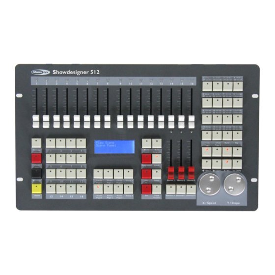
Overview
Fig. 1
4
Congratulations!
You have bought a great, innovative product from Showtec.
The
Showtec Showdesigner 512
brings excitement to any venue. Whether you want simple plug-&-play
action or a sophisticated DMX show, this product provides the effect you need.
You can rely on Showtec, for more excellent lighting products.
We design and manufacture professional light equipment for the entertainment industry.
New products are being launched regularly. We work hard to keep you, our customer, satisfied.
For more
information:
iwant@showtec.info
You can get some of the best quality, best priced products on the market from Showtec.
So next time, turn to Showtec for more great lighting equipment.
Always get the best — with Showtec !
Thank you!
Showdesigner 512
ORDERCODE 50721
Congratulations!
You have bought a great, innovative product from Showtec.
The Showtec Showdesigner 512 brings excitement to any venue. Whether you want simple plug-&-play action or a sophisticated DMX show, this product provides the effect you need.
You can rely on Showtec, for more excellent lighting products.
We design and manufacture professional light equipment for the entertainment industry.
New products are being launched regularly. We work hard to keep you, our customer, satisfied.
For more information : [email protected]
You can get some of the best quality, best priced products on the market from Showtec.
So next time, turn to Showtec for more great lighting equipment.
Always get the best — with Showtec !
Thank you!
Showtec
Showtec Showdesigner 512
™
Product Guide
Warning
……………………………………………………………………………………………………………………………………………………..2
Safety-instructions …………………………………………………………………………………………………………………………………2
Operating Determinations ……………………………………………………………………………………………………………………3
Return Procedure ………………………………………………………………………………………………………………………………….4
Claims ……………………………………………………………………………………………………………………………………………………4
Description
…………………………………………………………………………………………………………………………………………………5
Features ………………………………………………………………………………………………………………………………………………..5
Overview ……………………………………………………………………………………………………………………………………………….5
Controller front ………………………………………………………………………………………………………………………………………6
— Fixture selection buttons ………………………………………………………………………………………………………………6
— Sliders and LED indicators ……………………………………………………………………………………………………………6
— Function buttons ………………………………………………………………………………………………………………………….6
— Storage Area of Scene, Chase and Chase group ……………………………………………………………………..8
— Jog wheels …………………………………………………………………………………………………………………………………..8
— Master control ……………………………………………………………………………………………………………………………..9
Controller backside ………………………………………………………………………………………………………………………………9
Installation
………………………………………………………………………………………………………………………………………………. 10
Set Up and Operation
Operation ………………………………………………………………………………………………………………………………………….. 10
— Power on ………………………………………………………………………………………………………………………………….. 10
— Fixture selection ……………………………………………………………………………………………………………………….. 10
— Manual control ………………………………………………………………………………………………………………………… 10
— Clear ………………………………………………………………………………………………………………………………………… 11
— Clearing scenes, chases or chase groups ……………………………………………………………………………….. 11
— Create a scene ………………………………………………………………………………………………………………………… 11
— Run a scene ……………………………………………………………………………………………………………………………… 11
— Create a chase ……………………………………………………………………………………………………………………….. 11
— Run a chase ……………………………………………………………………………………………………………………………… 12
— Create a chase group …………………………………………………………………………………………………………….. 13
— Run a chase group ………………………………………………………………………………………………………………….. 13
— Jog wheel assignment …………………………………………………………………………………………………………….. 13
— Using the jog wheels ………………………………………………………………………………………………………………… 13
— Setup of slope channels …………………………………………………………………………………………………………… 14
— Delete ………………………………………………………………………………………………………………………………………. 14
— Create a master control ………………………………………………………………………………………………………….. 14
Maintenance
………………………………………………………………………………………………………………………………………….. 15
Troubleshooting
……………………………………………………………………………………………………………………………………… 15
Product Specifications
……………………………………………………………………………………………………………………………. 16
1
WARNING
CAUTION!
Keep this device away from rain and moisture!
FOR YOUR OWN SAFETY, PLEASE READ THIS USER MANUAL CAREFULLY
BEFORE YOUR INITIAL START-UP!
Unpacking Instructions
Immediately upon receiving this product, carefully unpack the carton and check the contents to ensure that all parts are present, and have been received in good condition. Notify the dealer immediately and retain packing material for inspection if any parts appear damaged from shipping or the carton itself shows signs of mishandling. Save the carton and all packing materials. In the event that a fixture must be returned to the factory, it is important that the fixture be returned in the original factory box and packing.
Your shipment includes:
• Showtec Showdesigner 512
• IEC powercable
• User manual
SAFETY INSTRUCTIONS
Every person involved with the installation, operation and maintenance of this device has to:
—
be qualified follow the instructions of this manual
CAUTION! Be careful with your operations.
With a dangerous voltage you can suffer a dangerous electric shock when touching the wires!
Before your initial start-up, please make sure that there is no damage caused by transportation. Should there be any, consult your dealer and do not use the device.
To maintain perfect condition and to ensure a safe operation, it is absolutely necessary for the user to follow the safety instructions and warning notes written in this manual.
Please consider that damages caused by manual modifications to the device are not subject to warranty.
This device contains no user-serviceable parts. Refer servicing to qualified technicians only.
IMPORTANT:
The manufacturer will not accept liability for any resulting damages caused by the nonobservance of this manual or any unauthorized modification to the device.
Never let the power-cord come into contact with other cables! Handle the power-cord and all connections with the mains with particular caution!
Never remove warning or informative labels from the unit.
Do not open the device and do not modify the device.
Do not insert objects into air vents.
Do not connect this device to a dimmerpack.
Do not switch the device on and off in short intervals, as this would reduce the device’s life.
Only use device indoor, avoid contact with water or other liquids.
2
Avoid flames and do not put close to flammable liquids or gases.
Always disconnect power from the mains, when device is not used or before cleaning! Only handle the power-cord by the plug. Never pull out the plug by tugging the power-cord.
Make sure that the device is not exposed to extreme heat, moisture or dust.
Make sure that the available voltage is not higher than stated on the rear panel.
Make sure that the power-cord is never crimped or damaged. Check the device and the powercord from time to time.
If device is dropped or struck, disconnect mains power supply immediately. Have a qualified engineer inspect for safety before operating.
If the device has been exposed to drastic temperature fluctuation (e.g. after transportation), do not switch it on immediately. The arising condensation water might damage your device. Leave the device switched off until it has reached room temperature.
If your Showtec device fails to work properly, discontinue use immediately. Pack the unit securely
(preferably in the original packing material), and return it to your Showtec dealer for service.
Repairs, servicing and electric connection must be carried out only by Showtec.
For replacement use fuses of same type and rating only.
This device falls under protection class I. Therefore it is essential to connect the yellow/green
conductor to earth.
WARRANTY: Till one year after date of purchase.
OPERATING DETERMINATIONS
This device is not designed for permanent operation. Consistent operation breaks will ensure that the device will serve you for a long time without defects.
If this device is operated in any other way, than the one described in this manual, the product may suffer damages and the warranty becomes void.
Any other operation may lead to dangers like short-circuit, burns, electric shock, lamp explosion, crash etc.
You endanger your own safety and the safety of others!
Improper installation can cause serious damage to people and property !
Connect the device to the mains with the power-plug.
Always pay attention, that the right color cable is connected to the right place.
International
L
N
EU (including UK)
From April 2004
Brown
Blue
North America
Black
White
Pin
Phase
Neutral
Green/Yellow Green Protective Earth
Make sure that the device is always connected properly to earth!
3
Return Procedure
Returned merchandise must be sent prepaid and in the original packing, call tags will not be issued.
Package must be clearly labeled with a Return Authorization Number (RMA number). Products returned without an RMA number will be refused. Highlite will not accept the returned goods or any responsibility.
Call Highlite 0031-455667723 or mail [email protected]
and request an RMA prior to shipping the fixture.
Be prepared to provide the model number, serial number and a brief description of the cause for the return. Be sure to properly pack fixture, any shipping damage resulting from inadequate packaging is the customer’s responsibility. Highlite reserves the right to use its own discretion to repair or replace product(s). As a suggestion, proper UPS packing or double-boxing is always a safe method to use.
Note: If you are given an RMA number, please include the following information on a piece of paper inside the box:
1) Your name
2) Your address
3) Your phone number
4) A brief description of the symptoms
Claims
The client has the obligation to check the delivered goods immediately upon delivery for any shortcomings and/or visible defects, or perform this check after our announcement that the goods are at their disposal. Damage incurred in shipping is the responsibility of the shipper; therefore the damage must be reported to the carrier upon receipt of merchandise.
It is the customer’s responsibility to notify and submit claims with the shipper in the event that a fixture is damaged due to shipping. Transportation damage has to be reported to us within one day after receipt of the delivery.
Any return shipment has to be made post-paid at all times. Return shipments must be accompanied with a letter defining the reason for return shipment. Non-prepaid return shipments will be refused, unless otherwise agreed in writing.
Complaints against us must be made known in writing or by fax within 10 working days after receipt of the invoice. After this period complaints will not be handled anymore.
Complaints will only then be considered if the client has so far complied with all parts of the agreement, regardless of the agreement of which the obligation is resulting.
4
Description of the device
Features
The Showdesigner is a light controller from Showtec and features:
• 512 DMX control channels, compatible with DMX512/ 1990 standard.
• Control up to 32 fixtures, each with up to 16 channels.
• 16 Sliders on the frontpanel for easy and fast control of all the channels in the fixture.
• LCD display with language selection English/German.
• 48 scenes for direct output and simultaneous running.
• Speed and slope of each chase can be adjusted either separate or together.
• Up to 200 steps in each chase; a maximum of 1700 steps can be stored
• 32 groups of chases run simultaneously, each with up to 48 chases; fade time and speed of each step
are adjustable.
• 3-pin DMX in/ out
• Photoelectric isolated data output, safe for up to 3kVdc, preventing the controller from damage
by eventual electric leakage from a defective fixture.
• All the pan/ tilt channels in different fixtures can be assigned to the jog wheels.
• When a chase is running, the slope channel can be configured as one with fixed pan/ tilt slope. The
gobo/ color channels can be set without slope to avoid unexpected effects.
• Built in audio input for sound activation.
• Built in switching power supply, suitable for all countries.
NOTE: Knowledge of DMX is required to fully utilize this unit.
Overview
Fig. 1
5
Controller Front
1. Fixture selection buttons
Page 1 and Page 2 each contain 16 fixtures which can be selected by the 16 buttons for fixture selection in combination with the
Page 1 (4.6)
and
Page 2 (4.6)
buttons. 16 DMX channels can be assigned to each fixture. If a fixture is selected, the LED indicator in the button will indicate it’s status. If the LED indicator of the fixture selection button blinks, the status of the fixture’s channels is indicated by the LEDs above the according faders.
Either one or several fixtures at the same time can be activated or deactivated.
Example
: to activate Fixture 4, 5, 6, 7, 8, 9 and 10 simultaneously, press and hold button 4 and press button 10. Now fixture 4, 5, 6, 7,8, 9 and 10 are all selected.
2. Faders and LED indicators
The unit has 16 faders, each with a LED indicator.
By using the Fixture buttons and the faders you can control all 512 channels in real time.
3. Function buttons
3.1 Release/Lightcopy
Release:
Manual control of the faders always overrides a chase or a scene during playback.
Moving a fader during playback will effect your output.
● Pressing the release button and moving the corresponding fader will release the
manual override for that channel.
Lightcopy:
Use this button for copying data from one fixture to another.
First, adjust the channels of one fixture by adjusting the faders, then press and hold
LightCopy + the current fixture selection until the LCD display shows:
Copy OK
.
Press and hold LightCopy again + the button of the target fixture until the display
Shows:
Paste OK
. Now you’ve copied the data of one fixture to another.
6
3.2 Clear/Exit
Clear:
The function of this button varies with the state of the device.
● Pressing the button clears the manual entry for the corresponding fader
● Pressing and holding the button for 3 seconds clears all manual entries for chases, faders, scenes and
groups.
Exit:
Press this button to exit the
program
or
delete
mode without saving your settings.
3.3 Blackout
Press this button to kill all output.
3.4 Pause
Press this button to pause all running chases.
3.5 Program
Press this button to enter Program-mode.
3.6 Add
Press this button to add a step while programming a chase or chase group.
3.7 All
When a chase is running, press this button to adjust the speed and slope for al the steps in the chase.
3.8 Del
Use this button to delete a scene/ chase/ chase group/ step while programming.
3.9 Latch
Press this button to latch two or more scenes/ chases/ chase groups to run simultaneously.
3.10 Swap
Press this button to swap the running of a different scene/ chase/ chase group (only one at a time).
3.11 Flash/Slopeset
Flash:
Press and hold this button, then select a scene, chase or chase group to run it
As long as the flash button is pressed.
Slopeset:
Press this button to assign a slope to a channel. The pan/ tilt channels controlled by the jog wheels have a fixed slope.
3.12 Music/Insert
When a chase is running, press this button to activate the sound mode.
Press this button to insert a step when programming.
3.13 Auto/Language
Auto:
Auto mode is the default chase running mode. Use this button to switch between sound mode and auto mode with preset speed and slope.
Language:
Press the
program (3.7)
button first and then press this button to switch between English and German language.
7
3.15 E/XY:
Use this button to switch between either speed/slope or pan/tilt function for the jog wheels.
Speed/slope mode:
LED is off.
The speed/ slope for a chase group can only be adjusted by
X/speed (5)
.
Pan/ tilt mode:
LED is on.
3.16 </SETX, >/SETY:
Use this buttons to change the direction of a running chase. Or use this button to switch between pan/tilt movement of the jog wheels.
3.17 Tap:
Tap this button to set the tempo of the running chase.
3.18 SelChase:
Press this button to select a running chase in order to change the settings.
4. Storage Area of Scene, Chase and Chase Group
4.1 Chase Page 1, Chase Page 2, Chase Page 3:
3 chase groups, each with 16 chases, total of 48 chases.
4.2 Scene Page 1, Scene Page 2, Scene Page 3:
3 scene pages, each with 16 scenes, total of 48 scenes.
4.3 Group 1, Group 2:
2 groups, each with 16 chase groups, total of 32 chase groups. Each chase group can store a sequence of up to 48 chases.
4.4 1-16:
16 number buttons for use of scenes, chases and chase groups.
LED Off: Contains no data
LED Flashing:
LED Blinks:
LED Lights continuously:
4.5 Multi:
Contains data
Data archive
Data active
Press this button to select two or more fixtures (LED indicator on).
If the LED indicator of this button is off, only one fixture can be
Selected.
4.6 Page 1, Page 2:
Page buttons. When the LED indicator of a page button is lit, the 16 fixtures stored in this page are ready for selection (see page 6:
Fixture selection buttons
).
8
5. Jog Wheels
5.1 X/Speed, Y/Slope:
Use to control the pan/ tilt of the fixtures (the pan/ tilt channels should be assigned to the jog wheels) and speed/ slope adjustment of chase and chase group.
6. Master control
6.1 Master control buttons
The master control buttons
Dimmer 1, Dimmer 2, Dimmer 3
are respectively used to enable/disable and setup the three master controls.
6.2 Master faders
Master faders
Master 1
,
Master 2
,
Master 3
are used to control the maximum output value of the assigned channels.
They only work when
Dimmer 1
,
Dimmer 2
,
Dimmer 3
are enabled (LED indicator on).
Controller Backside
Fig. 2
7. DMX Out 1:
This connector sends your DMX value to the DMX fixture or DMX pack.
8. DMX Out 2:
This connector sends your DMX value to the DMX fixture or DMX pack.
9. Data:
Data port .
10. Microphone
.
11. Audio Input:
This jack accepts a line level audio input signal ranged from 100 mV to 1Vpp.
12. MIDI In:
Not activated in the current software version.
13. MIDI Thru:
Not activated in the current software version.
14.
Main Fuse:
T1,5A/250V.
15. Power:
On/ Off.
16. IEC Connector
9
Installation
Remove all packing materials from the Showdesigner 512 . Check that all foam and plastic padding is removed. Screw the equipment into a 19″ rack. Connect all cables.
Always disconnect from electric mains power supply before cleaning or servicing.
Damages caused by non-observance are not subject to warranty.
Set Up and Operation
Before plugging the unit in, always make sure that the power supply matches the product specification voltage. Do not attempt to operate a 120V specification product on 230V power, or vice versa.
Operations
Power on
After powering on, the device will reset itself. The LED indicators will blink.
Fixture selection
After power on, the fixture buttons are deactivated and the sliders will not work. Press the fixture selection buttons to select the fixtures. If
Multi (4.5)
is activated (LED on), two or more fixtures can be selected.
Otherwise only one fixture at a time can be selected. When
Page 1 (4.6)
is activated, fixture 1-16 are ready for selection If
page 2 (4.6)
is selected, fixture 17-32 are ready for selection. If both
Page 1 (4.6)
and
Page 2 (4.6)
are active, two fixtures at a time will be selected.
Example:
Page1 (4.6)
and
Page 2 (4.6)
are both active. Selecting fixture1 will select both fixture 1 and fixture 17.
● 1-32 fixtures can be selected. If the LED indicator of the button is on, it means the fixture is selected.
The flashing LED indicators of the faders indicate that the fader value is 0.
● Two or more fixtures can be activated or deactivated simultaneously. E.g. If you want to activate or
deactivate 10 fixtures, press and hold the first button and then press the 10 th
button, now fixture 1-10 will
be either activated or deactivated simultaneously.
Manual control
After activating the fixtures, you can control the fixtures by moving the faders. If the fixtures do not response to the faders, move the fader to the bottom and try again. The brightness of the faders’ LED indicators give an indication of the output value. If the indicator is flashing it means the output value on the corresponding channel is 0. Manual control overrules the output caused by a running scene, chase or chase group. Press and hold
Release (3.1),
then move a fader, the manual override for that channel will be released.
Note:
Press and hold
Release (3.1)
, then move a fader to release the manual override of the corresponding channel, the LED indicator will dim. If a scene, chase or chase group is running on that channel, the brightness of the LED indicator will change according to the output value.
Press
clear (3.2)
shortly to clear all manual output. All the LED indicators of the sliders will dim.
Manual output overrides all output from a running scene, chase or chase group.
Clear
●
Pressing the Clear button will release the manual override for all faders.
● Pressing and holding the
Clear (3.2)
button for 3 seconds clears the manual override and all scenes,
chases or groups. For more info, see page 11:
2.2 Clearing scenes, chases or groups
.
10
Clearing scenes, chases or group pages
Clearing a entire group, scene or chase page is usefull to get a clean output when programming the console.
1.
Select the scene, chase or group page you want to clear.
Note:
All three pages from the chase or scene are released with this action so you don’t have to clear
each chase or scene page separately.
2.
Press and hold the
Clear (3.2)
button for 3 seconds.
3.
The LCD will show:
Release all chases
Create a scene
Scenes are simple saved positions, colors etc. which can be recalled by simply pressing a button.
1.
Always release all running functions in order to obtain a clean output.
See chapter 2.2 clearing scenes,
chases or group pages.
2.
Select the fixture(s) you want to use in your scene. (The LED of the selected fixture is lit) by pressing the
desired
fixture buttons (1)
.
3.
Adjust the faders to your liking. (If the fader does not respond, move the fader to zero and try again).
4.
Press the Program button to enter program mode. The LCD will show:
Program mode
.
5.
Select the scene page you wish to store your sene in by pressing the
Scene page 1 (4.2)
,
Scene page 2
(4.2)
or
Scene page 3 (4.2)
button.
The display will show:
Program mode
Scene Page x
(Where x stands for the Scene Page number).
6.
Select a scene you wish to store your settings in by pressing button
1 – 16 (4.4).
The scene will
automatically be stored under the number pressed before.
Note:
A flashing LED in a scene number button indicates it already contains a scene. You can’t
overwrite a scene number which is written. You need to use a scene number which is empty. If you
want to overwrite an excisting page, you have to delete the current scene first (see page 14:
Delete
).
Playing a scene
Before playing a scene, make sure to release manual override by pressing the
Clear (3.2)
button.
1.
Select the scene page you want to use by pressing the
Scene page 1 (4.2)
,
Scene page 2 (4.2)
or
Scene page 3 (4.2)
button.
The display will show:
Play Scene
Scene Page x
(Where x stands for the Scene Page number).
2.
Select a scene you wish to play by pressing button
1 – 16 (4.4).
Note:
Only scenes indicated by a flashing LED contain data ou can’t select an empty scene. The LED
of the selected scene will light up continuously. You can run multiple scenes at the same time by
repeating the instructions above.
Create a chase
There are three ways to create a chase:
A. Create a chase by adjusting the faders.
B. Create scenes first and then select the scenes into the chase.
C. Use a mix of the two ways described above.
Create a chase by adjusting the faders.
1.
Always release all running functions in order to obtain a clean output. See page :
clearing scenes,
chases or group pages.
2.
Press the
Program (3.5)
button to enter programming mode. The LCD will show:
Program mode
.
3.
Select the chase page you want to use by pressing the
Chase page 1 (4.1)
,
Chase page 2 (4.1)
or
Chase page 3 (4.1)
button.
The display will show:
Program mode
Chase Page x
(Where x stands for the Chase Page number.)
4.
Select a chase number you wish to store your settings in by pressing button
1 – 16 (4.4).
Note:
A flashing LED in a chase number button indicates it already contains a chase. You can not
overwrite a chase number which is written. You need to use a scene number which is empty. If you
want to overwrite an excisting chase, you have to delete this chase first (see page 14:
Delete
)
5.
Select the fixture(s) you want to use by pressing the
corresponding
Fixture buttons (1)
.
11
6.
Adjust your settings by moving the faders.
Note:
If a fader does not respond, move the fader to the zero position and try again.
7.
Adjust the Speed and Slope using the
X/Speed (5.1)
and
Y/Slope (5.1)
jog wheels.
8.
Press the
Add (3.6)
button to save the step. The console will repeat the step number with 1. Repeat 5 to
8 as many times you like up to a maximum of 200 steps.
9
. Press the
Program (3.5)
button to save the chase and exit programming mode.
Create the scenes first and then add the scenes into a chase.
1.
Always release all running functions in order to obtain a clean output.
See page clearing scenes,
chases or group pages.
2.
Press the Program button to enter program mode. The LCD will show:
Program mode
.
3.
Select the chase page you want to use by pressing the
Chase page 1 (4.1)
,
Chase page 2 (4.1)
or
Chase page 3 (4.1)
button.
The display will show:
Program mode
Chase Page X
(Where X stands for the Chase Page number.)
4.
Select a chase number you wish to store your settings in by pressing button
1 – 16 (4.4).
Note:
A flashing LED in a chase number button indicates it already contains a chase. You can not
overwrite a chase number which is written. You need to use a scene number which is empty. If you
want to overwrite an excisting chase, you have to delete this chase first (see page 14:
Delete
).
5.
Select the scene page you want to use by pressing the
Scene page 1 (4.2)
,
Scene page 2 (4.2)
or
Scene page 3 (4.2)
button.
The display will show:
Play Scene
Scene Page x
(Where x stands for the Scene Page number.)
6.
Select a scene you wish to use by pressing button
1 – 16 (4.4).
Note:
Only scenes indicated by a flashing LED contain data. You can’t select an empty scene.
The LED of the selected scene will light up continuously.
You can run multiple scenes at the same time by repeating step 5 and 6.
7.
Adjust the Speed and Slope using the
X/Speed (5.1)
and
Y/Slope (5.1)
jog wheels.
8.
Press the
Add (3.6)
button to save the step. The console will repeat the step number with 1. Repeat 5 to
8 as many times you like up to a maximum of 200 steps.
9
. Press the
Program (3.5)
button to save the chase and exit programming mode.
Note:
While making the light effect, the LED indicators of the relevant faders should be off. If not, you can press and hold
Release (3.1)
and then move the fader to release them. Any channel with an output value will be stored into the chase.
Running a chase
Before running a chase, make sure to release manual override by pressing the
Clear (3.2)
button.
1.
Select the chase page you want to use by pressing the
Chase page 1 (4.1)
,
Chase page 2 (4.1)
or
Chase page 3 (4.1)
button.
The display will show:
Run chase
Chase Page x
(Where x stands for the Scene Page number.)
2.
Select a chase you wish to play by pressing button
1 – 16 (4.4).
Note:
Only chases indicated by a flashing LED contain data. You can’t select an empty scene.
The LED of the selected scene will light up continuously.
You can run multiple chases at the same time by repeating the instructions above.
Note:
Different blinking frequencies of the number button show the different status. A high blinking rate means there is an existing chase stored in the button, but is not running. Full on means the chase is running and cannot be edited. A slow blinking rate means the chase is running and ready for editing.
Following parameters can be edited while a chase is running:
Direction of the chase:
/SETY (3.15)
button, the chase will run in forward direction.
/SETX (3.15)
button, the chase will run in reverse direction.
12
Tempo of the chase:
You can run the Showdesigner in either Auto mode or in music mode by respectively pressing the
Auto
(3.13)
button or the
Music (3.12)
button.
Auto mode
In automode you can adjust the speed by tapping the
Tap (3.17)
button. In auto mode you can adjust the speed and slope of each chase separately while turning the
X/Speed (5)
and
Y/Slope jog wheels (5)
.
Pressing and holding the
All (3.7)
button allows you to change the speed and slope of all scenes in a chase together.
Music mode
In music mode, the speed is dependent of the speed (BPM) of the audio signal connected to the
audio input (5)
or the beat of music picked up by the built in microphone on the back of the console.
Press
Clear (3.2)
and hold for about 3 second to close all running chases. If a chase is running and you are using manual control. The manual control will have priority.
Create a chase group
The controller can store up to 48 chase groups with up to 48 steps. The running time of each step can be adjusted from 0,5 seconds to 10 minutes. To create a chase group, please follow the steps below:
1.
Always release all running functions in order to obtain a clean output. (See page 11:
clearing scenes,
chases or group pages.)
2.
Press the
Program (3.5)
button to enter program mode.
The display will show:
Program mode
.
3.
Select the chase page you want to use by pressing the
Group 1 (4.3)
or
Group 2 (4.3)
button. The
display will show:
Program mode
Group Page X
(Where X stands for the Chase Page number.)
4.
Once the number button is pressed, the unit will automatically select
chase page 1 (4.1).
If desired
choose another chase page by pressing the one of the
Chase page buttons (4.1)
. A flashing LED
indicates that a chase is stored under the corresponding number.
5.
Select the desired chases to add to the chase group. Once selected, the chase will start running.
6.
Adjust the Speed and Slope using the
X/Speed (5)
and
Y/Slope (5)
jog wheels. Make sure the LED in
the
X/XY (3.14)
button is not lit.
7.
Press the
Add (3.6)
button to save the step. The console will increase repeat the step number. Repeat
step 4 to 7 as many times as you want. Up to a maximum of 48 steps can be added.
8
. Press the
Program (3.5)
button to save the chase and exit programming mode.
Note:
To Exit the programming mode, press clear for a few seconds.
Run a chase group
1.
Select
Group 1 (4.3)
or
Group 2 (4.3)
.
2.
The LED indicator of the number buttons containing a chase group will blink at a higher rate.
3.
Select the desired number button to run the chase group. The LED indicator’s blinking rate will slow
down, which means that the chase group is running now.
Note:
Press
Clear (3.2)
to close all running chase groups.
Jog wheel assignment
The pan/tilt channel of the fixtures can be assigned to the jog wheels on the controller for easy control.
Pan (X) movement
1.
Press the
Program (3.5)
button to enter program mode. The display will show:
Program mode
.
2.
Press the
/set X (3.15)
button the LED will blink.
3.
Select the fixture(s) you want to control by pressing the
Fixture selection buttons (1)
. The display will
show:
Program Mode
X Channel
4.
Move the fader of the channel you wish to use for the Pan function up and down until the LED blinks.
5.
Press the
/set X (3.15)
button again to save and exit the programming mode.
13
Tilt (Y) movement
1.
Press the
Program (3.5)
button to enter program mode. The display will show:
Program mode
.
2.
Press the
/set Y (3.15)
button the LED will blink.
3.
Select the fixture(s) you want to control by pressing the
Fixture selection buttons (1)
. The display will show:
Program Mode
Y Channel
4.
Move the fader of the channel you wish to use for the Tilt function up and down until the LED blinks.
5.
Press the
/set Y (3.15)
button again to save and exit the programming mode.
Using the jog wheels
The channel assigned to the jog wheel can be controlled by the jog wheel.
1.
Press the
E/XY (3.14)
button, make sure the LED indicator is on.
2.
Select the desired fixtures.
3.
Control the fixture with the jog wheels.
Setup of slope channels
The channels that have been assigned to the jog wheels will automatically have a slope assigned when the chase is running. Other channels can be set up with a slope also.
1.
Press the
Program (3.5)
button to enter program mode. The display will show:
Program mode
.
2.
Press the
Flash/SlopeSet (3.11)
button. The display will show:
Slope Channel
.
3.
Select the desired fixture.
4.
Move the channel(s) you wish to assign a slope to. If a channel is assigned, the LED will be lit. If you
made a mistake, press the
Release (3.1)
button and move the fader you want to release.
5.
Press the
Flash/SlopeSet (3.11)
button again. Now your setup is finished.
Example:
To assign a slope to channel 5 & 6 of fixture 1:
Press
Program
->
SlopeSet
-> Select Fixture
1
-> move the faders of CH5 & CH6 until the LED indicators are lit. ->
SlopeSet
. Ok.
Delete
1.
Press the
Del (3.8)
button.
2.
Select
Scene Page 1 (4.2)
,
Scene Page 2 (4.2)
,
Scene Page 3 (4.2)
,
Chase Page 1 (4.1)
,
Chase Page 2
(4.1)
,
Chase Page 3 (4.1)
,
Group 1 (4.3)
,
Group 2 (4.3)
,
</SetX (3.15)
,
>/SetY (3.15)
, or
Slopeset (3.11)
by
pressing the corresponding button.
3.
Press a
number 1-16 (4.4)
button to select the scene, chase or chasegroup you want to delete. Not
when you have selected
</SetX (3.15)
,
>/SetY (3.15)
, or
Slopeset (3.11).
4.
Now the Item is deleted.
Example
: Delete the chase stored in number button 2 of Chase 1. Press
Del
->
Chase1
->
2
. Ok.
Create a master control
1.
Press the
Program
button to enter programming mode. The LCD will show:
Program mode
.
2.
Select one of the three master controls by pressing the
Dimmer 1 (6.1)
,
Dimmer 2 (6.1)
or
Dimmer 3
(6.1)
. button. The display will show:
Program mode
Dimmer group: x
(Where x stands for the dimmer group number.)
3.
Select the fixture(s) you want to use by pressing the corresponding
Fixture button (1)
.
4.
Move the faders you like to add in the master control group until the corresponding LED is lit. Repeat
this for all faders yo like to add.
Note:
If a fader does not respond, move the fader to the zero position and try again.
5.
Press the
Dimmer 1 (6.1)
,
Dimmer 2 (6.1)
or
Dimmer 3 (6.1)
button again to save your settings.
Example
: We have an 8-channel dimmer pack. The DMX address is 17 which is the start address of the second fixture in the controller. Follow the steps below to program it into the
Dimmer
:
Program
->
Dimmer1
-> Fixture selection button
2
-> move fader 1-8 until their indicators are lit ->
Dimmer1
-> Ok.
Now, a master control is ready. Fader Master1 will control the maximum output of 1–8 in fixture 2.
14
Maintenance
The Showtec Showdesigner 512 re quires almost no maintenance. However, you should keep the unit clean. Disconnect the mains power supply, and then wipe the cover with a damp cloth. Do not immerse in liquid. Do not use alcohol or solvents.
Keep connections clean. Disconnect electric power, and then wipe the DMX and audio connections with a damp cloth. Make sure connections are thoroughly dry before linking equipment or supplying electric power.
Troubleshooting
Showtec Showdesigner 512
This troubleshooting guide is meant to help solve simple problems. If a problem occurs, carry out the steps below in sequence until a solution is found. Once the unit operates properly, do not carry out following steps.
1.
Fixture does not respond to controller: Check the DMX-address of the fixture and the controller.
Make sure they match. Make sure the connections are correct.
2.
Interference between chases; If the same channel is assigned to different running chases, the one
with the highest channel value will be put out.
3.
Note: when in programming mode, as long as the LED indicator is lit, the value will be stored, even if
the value is zero.
4.
Except for the channels assigned to the jog wheels and the channels set with slope, slope is not
assigned to the other channels.
5.
For the master controlled channels, the master sliders are valid only when the dimmer buttons are
activated (LED indicator is on). If some channels can’t be controlled, please check if they are
assigned to master control.
6.
If the device does not operate properly, unplug the device.
7.
Check power from the wall, all cables, the fuse, the settings (return to default), etc.
8.
If all of the above appears to be O.K., plug the unit in again.
9.
If nothing happens after 30 seconds, unplug the device.
10.
Return the device to your Showtec dealer.
15
Product Specification
Model: Showtec Showdesigner 512
Power input : AC 100V-240V, 50/60Hz, 30W.
DMX-Output: 3-pin female XLR
MIDI-Signal: 5-pin standard interface
Audio Input: 100 mV~1Vpp.
Fuse: F1.5A 250V 5×20 mm
Dimensions : 480 x 290 x 95 mm (LxWxH)
Weight : 5,1 kg
Design and product specifications are subject to change without prior notice.
Website: www.Showtec.info
Email: [email protected]
16