- Manuals
- Brands
- Deep Sea Electronics Plc Manuals
- Control Unit
- DSE6120 MKII
- Operator’s manual
-
Contents
-
Table of Contents
-
Bookmarks
Quick Links
DEEP SEA ELECTRONICS PLC
DSE6110 MKII & DSE6120 MKII Operator
Manual
Document Number: 057-236
Author: Mark Graham
057-236 ISSUE: 1
Related Manuals for Deep Sea Electronics Plc DSE6120 MKII
Summary of Contents for Deep Sea Electronics Plc DSE6120 MKII
-
Page 1
DEEP SEA ELECTRONICS PLC DSE6110 MKII & DSE6120 MKII Operator Manual Document Number: 057-236 Author: Mark Graham 057-236 ISSUE: 1… -
Page 2
The DSE logo is a UK registered trademarks of Deep Sea Electronics PLC. Any reference to trademarked product names used within this publication is owned by their respective companies. Deep Sea Electronics Plc reserves the right to change the contents of this document without prior notice. Amendments List… -
Page 3: Table Of Contents
DSE6110 MKII & DSE6120 MKII Operator Manual TABLE OF CONTENTS Section Page INTRODUCTION ………………..6 BIBLIOGRAPHY ………………….7 1.1.1 INSTALLATION INSTRUCTIONS …………….7 1.1.2 TRAINING GUIDES ………………..7 1.1.3 MANUALS …………………… 7 1.1.4 THIRD PARTY DOCUMENTS ……………… 7 SPECIFICATION ………………..8 SHORT NAMES ………………….
-
Page 4
TYPICAL WIRING DIAGRAM ………………34 3.2.1 DSE6110 MKII TYPICAL WIRING DIAGRAM (3 PHASE 4 WIRE) ……35 3.2.2 DSE6120 MKII TYPICAL WIRING DIAGRAM (3 PHASE 4 WIRE) ……36 ALTERNATE TOPOLOGY WIRING DIAGRAMS …………37 3.3.1 GENERATOR ………………….37 3.3.2 MAINS (6120 MKII ONLY) ……………… -
Page 5
DSE6110 MKII & DSE6120 MKII Operator Manual 5.6.2 MANUAL MODE………………… 66 5.6.3 TEST MODE ………………….66 5.6.4 AUTO MODE ………………….66 PROTECTIONS ………………… 67 ALARMS ……………………67 6.1.1 ECU ALARMS (CAN ERROR MESSAGE / DTC) ……….. 68 INDICATIONS ………………….. 69 WARNING ALARMS ………………… -
Page 6: Introduction
The DSE61xx MKII series module has been designed to allow the operator to start and stop the generator, and if required, transfer the load to the generator either manually or automatically. Additionally, the DSE6120 MKII automatically starts and stops the generator set depending upon the status of the mains (utility) supply.
-
Page 7: Bibliography
DSE Part Description 057-004 Electronic Engines and DSE Wiring Guide 057-224 DSE6110 MKII & DSE6120 MKII Configuration Suite PC Software Manual 1.1.4 THIRD PARTY DOCUMENTS The following third party documents are also referred to: Reference Description IEEE Std C37.2-1996 IEEE Standard Electrical Power System Device ISBN 1-55937-879-4 Function Numbers and Contact Designations.
-
Page 8: Specification
All modules in the DSE6000 MKII range. DSE6100,DSE61xx MKII All modules in the DSE61xx MKII range. DSE6110 MKII DSE6110 MKII module/controller DSE6120 MKII DSE6120 MKII module/controller 2.2 OPERATING TEMPERATURE Module Description DSE61xx MKII -30 ºC +70 ºC (-22 ºF +158 ºF ) Display Heater Variants -40 ºC +70 ºC (-40 ºF +158 ºF )
-
Page 9: Terminal Specification
Specification 2.4 TERMINAL SPECIFICATION NOTE: For purchasing additional connector plugs from DSE, please see the section entitled Maintenance, Spares, Repair and Servicing elsewhere in this document. Two part connector. Male part fitted to • module Female part supplied in • Connection Type module packing case — Screw terminal, rising…
-
Page 10: Voltage & Frequency Sensing
Specification 2.6 VOLTAGE & FREQUENCY SENSING Measurement Type True RMS conversion Sample Rate 5 kHz or better Harmonics Up to 11 or better Input Impedance 300 kΩ phase to neutral 15 V to 415 V AC (absolute maximum) (minimum required for sensing frequency Phase To Neutral Suitable for 345 V AC nominal (±20 % for under/overvoltage detection)
-
Page 11: Va Rating Of The Cts
Specification 2.7.1 VA RATING OF THE CTS NOTE: Details for 4 mm² cables are shown for reference only. The connectors on the DSE modules are only suitable for cables up to 2.5 mm². The VA burden of the module on the CTs is 0.5 VA. However depending upon the type and length of cabling between the CTs and the module, CTs with a greater VA rating than the module are required.
-
Page 12: Ct Polarity
Specification 2.7.2 CT POLARITY NOTE: Take care to ensure correct polarity of the CT primary as shown above. If in doubt, check with the CT supplier. Take care to ensure the correct polarity of the CTs. Incorrect CT orientation leads to negative kW readings when the set is supplying power.
-
Page 13: Inputs
Specification 2.8 INPUTS 2.8.1 DIGITAL INPUTS 6 configurable digital inputs Number (10 when Analogue Inputs are configured as digital inputs) Arrangement Contact between terminal and ground Low Level Threshold 3.2 V minimum High Level Threshold 8.1 V maximum Maximum Input Voltage +60 V DC with respect to plant supply negative Minimum Input Voltage -24 V DC with respect to plant supply negative…
-
Page 14: 0-10V Input Configuration
Specification 2.8.2.1.2 0-10V INPUT CONFIGURATION Number 1 configurable ratiometric input Full Scale 0 V to 10 V Resolution Accuracy +/-2% of full scale voltage (±0.2 V) excluding transducer error Max Common Mode Voltage ±2 V 0 % to 250 %, 0 °C to 250 °C (32 °F to 482 °F) or 0 bar to 17.2 bar Display Range (0 PSI to 250 PSI) subject to limits of the sensor and sensor configuration…
-
Page 15: Analogue Input C
Specification 2.8.2.3 ANALOGUE INPUT C Flexible: Configured for Fuel Level Sensor in the DSE default configuration Input Type Flexible Options: Not used, Digital Input, Flexible Analogue & Fuel Level Sensor Pressure Sensor Flexible Input Selection Percentage Sensor Temperature Sensor Resistance measurement by measuring voltage across sensor with Measurement Type a fixed current applied Arrangement…
-
Page 16: Charge Fail Input
Specification 2.8.3 CHARGE FAIL INPUT Minimum Voltage Maximum Voltage 35 V (plant supply) Resolution 0.2 V Accuracy ±1 % of max measured voltage Excitation Active circuit constant power output Output Power 2.5 W nominal at 12 V and 24 V Current At 12V 210 mA Current At 24V…
-
Page 17: Communication Ports
Specification 2.10 COMMUNICATION PORTS USB 2.0 Device for connection to PC running DSE configuration suite only. USB Port Max distance 6m (18 yards) NOTE: For additional length, the DSE124 CAN Extender is available. For more information, refer to DSE Publication: 057-116 DSE124 Operator Manual CAN Port Engine CAN Port Standard implementation of ‘Slow mode’, up to 250 K bits/s…
-
Page 18: Usb Connection
Additionally, the various operating parameters (such as output volts, oil pressure, etc.) of the remote generator are available to be viewed or changed. To connect a module to a PC by USB, the following items are required: DSE6110 MKII & DSE6120 MKII Controller • DSE Configuration Suite PC Software •…
-
Page 19: Dsenet® (Expansion Modules)
DSENet® link. For connection details, refer to section entitled Typical Wiring Diagram elsewhere in this document. NOTE: DSE6110 MKII & DSE6120 MKII modules does not support the DSE2510 or DSE2520 display modules. DSENet® is the interconnection cable between the host controller and the expansion module(s) and must not be connect to any device other than DSE equipment designed for connection to the DSENet®…
-
Page 20: Adding An External Sounder
Specification 2.11 ADDING AN EXTERNAL SOUNDER Should an external alarm or indicator be required, this can be achieved by using the DSE Configuration Suite PC software to configure an auxiliary output for Audible Alarm, and by configuring an auxiliary input for Alarm Mute (if required). The audible alarm output activates and de-activates at the same time as the module’s internal sounder.
-
Page 21: Dimensions And Mounting
Specification 2.13 DIMENSIONS AND MOUNTING 2.13.1 DIMENSIONS 216 mm x 158 mm x 43 mm (8.5” x 6.2” x 1.7”) 2.13.2 PANEL CUTOUT 184 mm x 137 mm (7.2” x 5.3”) 2.13.3 WEIGHT 0.45 kg (1.00 lb) 218 mm (8. 5 “) 43 mm (1.7 “) 33 mm (1.3 “) Page 21 of 94…
-
Page 22: Fixing Clips
Specification 2.13.4 FIXING CLIPS NOTE: In conditions of excessive vibration, mount the module on suitable anti-vibration mountings. The module is held into the panel fascia using the supplied fixing clips. Withdraw the fixing clip screw (turn anticlockwise) until only the pointed end is protruding •…
-
Page 23: Silicon Sealing Gasket
Specification 2.13.5 SILICON SEALING GASKET NOTE: For purchasing a silicon gasket from DSE, see the section entitled Maintenance, Spares, Repair and Servicing elsewhere in this document. The optional silicon gasket provides improved sealing between module and the panel fascia. The gasket is fitted to the module before installation into the panel fascia. Take care to ensure the gasket is correctly fitted to the module to maintain the integrity of the seal.
-
Page 24: Applicable Standards
Specification 2.13.6 APPLICABLE STANDARDS This document conforms to BS4884-1 1992 Specification for BS 4884-1 presentation of essential information. BS 4884-2 This document conforms to BS4884-2 1993 Guide to content BS 4884-3 This document conforms to BS4884-3 1993 Guide to presentation BS EN 60068-2-1 -30 °C (-22 °F) (Minimum temperature)
-
Page 25
Specification IEEE C37.2 Continued (Standard Electrical 50 – Instantaneous Overcurrent Relay Power System Device 52 – AC Circuit Breaker Function Numbers and Contact Designations) 53 – Exciter Or DC Generator Relay 54 – Turning Gear Engaging Device 59AC – AC Overvoltage Relay 59DC –… -
Page 26: Enclosure Classifications
Specification 2.13.7 ENCLOSURE CLASSIFICATIONS 2.13.7.1 IP CLASSIFICATIONS The modules specification under BS EN 60529 Degrees of protection provided by enclosures IP65 (Front of module when module is installed into the control panel with the optional sealing gasket). IP42 (front of module when module is installed into the control panel WITHOUT being sealed to the panel) First Digit Second Digit Protection against contact and ingress of solid objects…
-
Page 27: Nema Classifications
Specification 2.13.7.2 NEMA CLASSIFICATIONS THE MODULES NEMA RATING (APPROXIMATE) 12 (Front of module when module is installed into the control panel with the optional sealing gasket). 2 (front of module when module is installed into the control panel WITHOUT being sealed to the panel) NOTE: There is no direct equivalence between IP / NEMA ratings.
-
Page 28: Installation
Installation 3 INSTALLATION The module is designed to be mounted on the panel fascia. For dimension and mounting details, see the section entitled Specification, Dimension and mounting elsewhere in this document. 3.1 TERMINAL DESCRIPTION NOTE: Availability of some terminals depends upon module version. Full details are given in the section entitled Terminal Description elsewhere in this manual.
-
Page 29: Dc Supply, Estop Input, Dc Outputs & Charge Fail Input
Installation 3.1.1 DC SUPPLY, ESTOP INPUT, DC OUTPUTS & CHARGE FAIL INPUT NOTE: When the module is configured for operation with an electronic engine, FUEL and START output requirements may be different. For further details on connection to electronic engines, refer to DSE Publication: 057-004 Electronic Engines And DSE Wiring NOTE: For further details of module configuration, refer to DSE Publication: 057-224 DSE6110 MKII &…
-
Page 30: Analogue Sensors, Mpu, Can
Installation 3.1.2 ANALOGUE SENSORS, MPU, CAN NOTE: It is VERY important that terminal 11 (sensor common) is soundly connected to an earth point on the ENGINE BLOCK, not within the control panel, and must be a sound electrical connection to the sensor bodies. This connection MUST NOT be used to provide an earth connection for other terminals or devices.
-
Page 31: Dsenet
Installation 3.1.3 DSENET® NOTE: For further details of module configuration, refer to DSE Publication: 057-224 DSE6110 MKII & 6120 MKII Configuration Software Manual. NOTE: As a termination resistor is internally fitted to the controller, the controller must be the ‘first’ unit on the DSENet link. A termination resistor MUST be fitted to the ‘last’ unit on the DSENet®…
-
Page 32: Current Transformers
Installation 3.1.5 CURRENT TRANSFORMERS WARNING!: Do not disconnect this plug when the CTs are carrying current. Disconnection open circuits the secondary of the C.T.’s and dangerous voltages may then develop. Always ensure the CTs are not carrying current and the CTs are short circuit connected before making or breaking connections to the module.
-
Page 33: Configurable Digital Inputs
Typically, they extend USB up to 50 m. The supply and support of this type of equipment is outside the scope of Deep Sea Electronics PLC. CAUTION!: Care must be taken not to overload the PCs USB system by connecting more than the recommended number of USB devices to the PC.
-
Page 34: Typical Wiring Diagram
Installation 3.2 TYPICAL WIRING DIAGRAM As every system has different requirements, these diagrams show only a TYPICAL system and do not intend to show a complete system. Genset manufacturers and panel builders may use these diagrams as a starting point; however, you are referred to the completed system diagram provided by your system manufacturer for complete wiring detail.
-
Page 35: Dse6110 Mkii Typical Wiring Diagram (3 Phase 4 Wire)
Installation 3.2.1 DSE6110 MKII TYPICAL WIRING DIAGRAM (3 PHASE 4 WIRE) Page 35 of 94 057-236 ISSUE: 1…
-
Page 36: Dse6120 Mkii Typical Wiring Diagram (3 Phase 4 Wire)
Installation 3.2.2 DSE6120 MKII TYPICAL WIRING DIAGRAM (3 PHASE 4 WIRE) 057-236 ISSUE: 1 Page 36 of 94…
-
Page 37: Alternate Topology Wiring Diagrams
Installation 3.3 ALTERNATE TOPOLOGY WIRING DIAGRAMS 3.3.1 GENERATOR Page 37 of 94 057-236 ISSUE: 1…
-
Page 38: Mains (6120 Mkii Only)
Installation 3.3.2 MAINS (6120 MKII ONLY) 057-236 ISSUE: 1 Page 38 of 94…
-
Page 39: Earth Systems
Installation 3.4 EARTH SYSTEMS 3.4.1 NEGATIVE EARTH The typical wiring diagrams located within this document show connections for a negative earth system (the battery negative connects to Earth) 3.4.2 POSITIVE EARTH When using a DSE module with a Positive Earth System (the battery positive connects to Earth), the following points must be followed: Follow the typical wiring diagram as normal for all sections EXCEPT the earth points •…
-
Page 40: Typical Arrangement Of Dsenet
3.5 TYPICAL ARRANGEMENT OF DSENET® NOTE: For further details of module configuration, refer to DSE Publication: 057-224 DSE6110 MKII & DSE6120 MKII Configuration Software Manual. Six (6) devices can be connected to the DSENet®, made up of the following devices :…
-
Page 41: Description Of Controls
Control of the module is via push buttons mounted on the front of the module with Stop/Reset Mode , Manual Mode , Test Mode (DSE6120 MKII Only), Auto Mode Start functions. For normal operation, these are the only controls which need to be operated. Details of their operation are provided later in this document.
-
Page 42: Dse6110 Mkii
Description Of Controls 4.1 DSE6110 MKII Menu Module Fault LED. Navigation Display constant on warning and flash upon Electrical Trip and Shutdown Fault Close Open Generator Generator (Manual Mode (Manual Mode Only) Only) Start Stop / Reset Manual Auto Alarm Mute Mode Mode Mode…
-
Page 43: Dse6120 Mkii
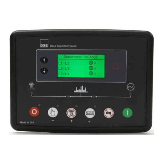
Description Of Controls 4.2 DSE6120 MKII Menu Module Fault LED. Navigation Display constant on warning and flash upon Electrical Trip and Shutdown Fault Transfer to Transfer to Mains Generator (Manual Mode (Manual Mode Only) Only) Start Stop / Reset Manual…
-
Page 44: Control Push-Buttons
Stop/Reset Mode or Auto Mode For further details, please see section entitled ‘Operation’ elsewhere in this manual. Test Mode (DSE6120 MKII Only) This button places the module into its Test Mode . Once in Test Mode , the module responds to the Start button to start the generator and run it off load.
-
Page 45
Description Of Controls Icon Description Auto Mode This button places the module into its Auto Mode . This mode allows the module to control the function of the generator automatically. The module monitors the remote start input and once a start request is made, the set is automatically started and placed on load (Close Generator and Delayed Load Output 1, 2, 3 &… -
Page 46
This button is only active in the Manual Mode and allows the operator to open the generator breaker and remove the load. Transfer To Mains (DSE6120 MKII Only) This button is only active in the Manual Mode and allows the operator to transfer the load to the mains. -
Page 47: Viewing The Instrument
NOTE: Depending upon the module’s configuration, some display screens may be disabled. For further details of module configuration, refer to DSE Publication: 057-224 DSE6110 MKII & DSE6120 MKII Configuration Software Manual. It is possible to scroll to display the different pages of information by pressing and holding either of the Menu Navigation buttons for two seconds to move to the next or previous page.
-
Page 48: Status
Description Of Controls 4.4.1 STATUS This is the ‘home’ page, the page that is displayed when no other page has been selected, and the page that is automatically displayed after a period of inactivity (LCD Page Timer) of the module control buttons.
-
Page 49: Engine
Description Of Controls 4.4.2 ENGINE NOTE*: For further details of support engine, refer to DSE Publication: 057-004 Electronic Engines and DSE Wiring Guide. These pages contain instrumentation gathered about the engine measured or derived from the module’s inputs, some of which may be obtained from the engine ECU. Engine 1500 RPM Engine Speed…
-
Page 50: Generator
For further details of module configuration, refer to DSE Publication: 057-224 DSE6110 MKII & DSE6120 MKII Configuration Software Manual. These Pages contain electrical values of the mains, measured or derived from the module’s voltage inputs.
-
Page 51: Expansion
NOTE: Depending upon the module’s configuration, some display screens may be disabled. For further details of module configuration, refer to DSE Publication: 057-224 DSE6110 MKII & DSE6120 MKII Configuration Software Manual. When input expansion modules are configured, these pages contain measured values derived from the expansion analogue inputs.
-
Page 52: Alarms
Description Of Controls 4.4.6 ALARMS When an alarm is active, the Common Alarm LED, illuminates and a message appears on the module’s display. If configured, the external audible alarm also sounds. The external audible alarm is silenced by pressing the Alarm Reset / Lamp Test button.
-
Page 53: Ecu Alarms (Can Error Message / Dtc)
Description Of Controls 4.4.6.1 ECU ALARMS (CAN ERROR MESSAGE / DTC) NOTE: For details on these code meanings, refer to the ECU instructions provided by the engine manufacturer, or contact the engine manufacturer for further assistance. NOTE: For further details on connection to electronic engines, refer to DSE Publication: 057-004 Electronic Engines And DSE Wiring When connected to a suitable CAN engine, the controller displays alarm status messages from the ECU.
-
Page 54: Event Log
4.4.7 EVENT LOG NOTE: For further details of module configuration, refer to DSE Publication: 057-224 DSE6110 MKII & DSE6120 MKII Configuration Software Manual. The module maintains a log of past alarms and/or selected status changes. The log size has been increased in the module over past module updates and is always subject to change.
-
Page 55: Lcd Inicators
4.4.8 LCD INICATORS NOTE: For further details of module configuration, refer to DSE Publication: 057-224 DSE6110 MKII & DSE6120 MKII Configuration Software Manual. These LCD Indicators are configured by the user to indicate any one of 100+ different functions based around the following:- •…
-
Page 56: About
4.4.10.2 SUPPORT STRINGS NOTE: For further details of module configuration, refer to DSE Publication: 057-224 DSE6110 MKII & DSE6120 MKII Configuration Software Manual. The support string pages are intended to contain important information about the generator supplier company such as contact information. The contents of these screens vary depending upon configuration by the engine manufacturer or supplier.
-
Page 57: Operation
Operation 5 OPERATION NOTE: The following descriptions detail the sequences followed by a module containing the standard ‘factory configuration’. Always refer to your configuration source for the exact sequences and timers observed by any particular module in the field. 5.1 QUICKSTART GUIDE This section provides a quick start guide to the module’s operation.
-
Page 58: Stopping The Engine
Operation 5.1.2 STOPPING THE ENGINE NOTE: For further details, see the section entitled ‘OPERATION’ elsewhere in this manual. Select Stop/Reset mode. The generator is stopped 057-236 ISSUE: 1 Page 58 of 94…
-
Page 59: Stop/Reset Mode
Viewing the instruments and event logs is NOT affected by Panel Lock. NOTE: For further details of module configuration, refer to DSE Publication: 057-224 DSE6110 MKII & DSE6120 MKII Configuration Software Manual. Stop/Reset Mode is activated by pressing the Stop/Reset Mode button.
-
Page 60: Manual Mode
CAN. NOTE: For further details of module configuration, refer to DSE Publication: 057-224 DSE6110 MKII & DSE6120 MKII Configuration Software Manual. The fuel relay is energised and the engine is cranked. If the engine fails to fire during this cranking attempt then the starter motor is disengaged for the Crank Rest Timer duration after which the next start attempt is made.
-
Page 61: Engine Running
A loading request can come from a number of sources. Press the Transfer to Generator button • Failure of mains supply (DSE6120 MKII only) • Activation of an auxiliary input that has been configured to Remote Start On Load or Auxiliary •…
-
Page 62: Test Mode
CAN. NOTE: For further details of module configuration, refer to DSE Publication: 057-224 DSE6110 MKII & DSE6120 MKII Configuration Software Manual. The fuel relay is energised and the engine is cranked. If the engine fails to fire during this cranking attempt then the starter motor is disengaged for the crank rest duration after which the next start attempt is made.
-
Page 63: Engine Running
Press the Manual Mode button followed by the Open Generator (DSE6110 MKII Only) • or Transfer to Mains (DSE6120 MKII Only) button. Press the Auto Mode button to return to automatic mode. The set observes all • Auto Mode start requests and stopping timers before beginning the Auto Mode Stopping Sequence.
-
Page 64: Automatic Mode
CAN and transmit the engine speed to the DSE controller. NOTE: For further details of module configuration, refer to DSE Publication: 057-224 DSE6110 MKII & DSE6120 MKII Configuration Software Manual. To allow for ‘false’ start requests, the start delay timer begins.
-
Page 65: Engine Running
Operation 5.5.3 ENGINE RUNNING NOTE: The load transfer signal remains inactive until the Oil Pressure has risen. This prevents excessive wear on the engine. The generator is placed on load if configured to do so. If all start requests are removed, the stopping sequence begins. 5.5.4 STOPPING SEQUENCE The Return Delay timer operates to ensure that the starting request has been permanently removed and isn’t just a short term removal.
-
Page 66: Scheduler
Operation 5.6 SCHEDULER The controller contains an inbuilt exercise run scheduler, capable of automatically starting and stopping the set. Up to 8 scheduled start/stop sequences can be configured to repeat on a 7-day or 28-day cycle. Scheduled runs may be on load or off load depending upon module configuration. Example Screen capture from DSE Configuration Suite Software showing the configuration of the…
-
Page 67: Protections
Protections 6 PROTECTIONS 6.1 ALARMS When an alarm is active, the Common Alarm LED, illuminates and a message appears on the module’s display. If configured, the external audible alarm also sounds. The external audible alarm is silenced by pressing the Alarm Reset / Lamp Test button.
-
Page 68: Ecu Alarms (Can Error Message / Dtc)
Protections 6.1.1 ECU ALARMS (CAN ERROR MESSAGE / DTC) NOTE: For details on these code meanings, refer to the ECU instructions provided by the engine manufacturer, or contact the engine manufacturer for further assistance. NOTE: For further details on connection to electronic engines, refer to DSE Publication: 057-004 Electronic Engines And DSE Wiring When connected to a suitable CAN engine, the controller displays alarm status messages from the ECU.
-
Page 69: Indications
Protections 6.2 INDICATIONS Indications are non-critical and often status conditions. They do not appear on the LCD display of the module as a text message in the Status, Event Log or Alarms pages. However, an output or LCD indicator is configured to draw the operator’s attention to the event. Example Input configured for •…
-
Page 70: Warning Alarms
Protections 6.3 WARNING ALARMS Warnings are non-critical alarm conditions and do not affect the operation of the engine system, they serve to draw the operators attention to an undesirable condition. Example Alarms High Coolant Temperature Warning In the event of an alarm the LCD jumps to the alarms page, and scroll through all active alarms. By default, warning alarms are self-resetting when the fault condition is removed.
-
Page 71
Protections Fault Description NOTE: Fail to Stop could indicate a faulty oil pressure sensor. If engine is at rest check oil sensor wiring and Fail To Stop configuration. The module has detected a condition that indicates that the engine is running when it has been instructed to stop. measured configured trip level for a kW has risen above the… -
Page 72: Electrical Trip Alarms
Protections ELECTRICAL TRIP ALARMS NOTE: The alarm condition must be rectified before a reset takes place. If the alarm condition remains, it is not possible to reset the unit (The exception to this is the Low Oil Pressure alarm and similar active from safety on alarms, as the oil pressure is low with the engine at rest).
-
Page 73
Protections Fault Description The module detects that the Maintenance Alarm 1 is due creating Maintenance Alarm 1 a fault condition, the appropriate LCD message is displayed. The module detects that the Maintenance Alarm 2 is due creating Maintenance Alarm 2 a fault condition, the appropriate LCD message is displayed. -
Page 74: Shutdown Alarms
Protections 6.5 SHUTDOWN ALARMS NOTE: The alarm condition must be rectified before a reset takes place. If the alarm condition remains, it is not be possible to reset the unit (The exception to this is the Low Oil Pressure alarm and similar active from safety on alarms, as the oil pressure is low with the engine at rest).
-
Page 75
Protections Fault Description The module detects the DSE Net link to the expansion module has Expansion Unit Failure failed or communications to the expansion module has been lost. measured configured trip level for a kW has risen above the Generator kW Overload configured duration. -
Page 76: High Current Shutdown / Electrical Trip Alarm
Protections 6.6 HIGH CURRENT SHUTDOWN / ELECTRICAL TRIP ALARM The overcurrent alarm combines a simple warning trip level with a fully functioning IDMT curve for thermal protection. 6.6.1 IMMEDIATE WARNING If the Immediate Warning is enabled, the controller generates a warning alarm as soon as the Trip level is reached.
-
Page 77: Idmt Alarm
Protections 6.6.2 IDMT ALARM If the IDMT Alarm is enabled, the controller begins following the IDMT ‘curve’ when the trip level is passed. If the Trip is surpassed for an excess amount of time the IDMT Alarm triggers (Shutdown or Electric trip as selected in Action).
-
Page 78
Protections Slower than Factory setting Factory setting (Time Multiplier = 36 Faster than Factory setting (Time Multiplier = 18 ‘Fastest’ trip setting (Time Multiplier = 1 057-236 ISSUE: 1 Page 78 of 94… -
Page 79: Maintenance Alarm
Protections 6.7 MAINTENANCE ALARM Depending upon module configuration one or more levels of engine maintenance alarm may occur based upon a configurable schedule. Example 1 Screen capture from DSE Configuration Suite Software showing the configuration of the Maintenance Alarm for 1, 2 and 3. When activated, the maintenance alarm is either a Warning (set continues to run) or Shutdown…
-
Page 80: Front Panel Configuration
Front Panel Configuration 7 FRONT PANEL CONFIGURATION This configuration mode allows the operator to fully configure the module through its display without the use of the DSE Configuration Suite PC Software. Use the module’s facia buttons to traverse the menu and make value changes to the parameters: Previous Section (Generator,Engine) Next Section…
-
Page 81: Front Panel Configuration Edtior
Front Panel Configuration 7.1 FRONT PANEL CONFIGURATION EDTIOR 7.1.1 ACCESSING THE FRONT PANEL CONFIGURATION EDITOR NOTE: More comprehensive module configuration is possible via PC configuration software. For further details of module configuration, refer to DSE Publication: 057- 224 DSE6110 MKII & DSE6110 MKII Configuration Software Manual. Ensure the engine is at rest and the module by pressing the Stop/Reset Mode button.
-
Page 82: Editing A Parameter
Front Panel Configuration 7.1.3 EDITING A PARAMETER NOTE: Pressing and holding the Menu Navigation buttons provides the auto- repeat functionality. Values can be changed quickly by holding the navigation buttons for a prolonged period of time. Press and hold either of the Menu Navigation buttons to cycle to the section which is •…
-
Page 83: Adjustable Parameters
Front Panel Configuration 7.1.5 ADJUSTABLE PARAMETERS Section Parameter as Shown on Display Values Pin Entry # # # # Display Contrast Language English — Others LCD Page Timer Scroll Delay Current Date and Time Day — hh:mm:ss Alt Config Default Config Default Config Engine Oil Pressure Low Shutdown…
-
Page 84
Cool Down Time Fail To Stop Delay Battery Under Voltage Warning Delay Battery Over Voltage Warning Delay Return Delay Generator Transient Delay Mains Transient Delay (DSE6120 MKII only) Mains Transfer Time (DSE6120 MKII only) Active, Inactive Scheduler Schedule Schedule Period… -
Page 85: Running’ Configuration Editor
Front Panel Configuration 7.2 ‘RUNNING’ CONFIGURATION EDITOR 7.2.1 ACCESSING THE ‘RUNNING’ CONFIGURATION EDITOR The ‘running’ editor can be entered whilst the engine is running. All protections remain active if • the engine is running while the running editor is entered Press and hold together the Menu Navigation buttons to access the Running Editor •…
-
Page 86: Exiting The ‘Running’ Configuration Editor
Front Panel Configuration 7.2.4 EXITING THE ‘RUNNING’ CONFIGURATION EDITOR NOTE: The editor automatically exits after 5 minutes of inactivity to ensure security. Press and hold the Stop/Reset Mode button to exit the editor without saving changes. • Press and hold the Tick button to exit the editor and save the changes.
-
Page 87: Commissioning
Fault Finding 8 COMMISSIONING NOTE: If Emergency Stop feature is not required, link the input to the DC Positive. Before the system is started, it is recommended that the following checks are made:- The unit is adequately cooled and all the wiring to the module is of a standard and rating •…
-
Page 88: Fault Finding
Fault Finding 9 FAULT FINDING NOTE: The below fault finding is provided as a guide check-list only. As the module can be configured to provide a wide range of different features, always refer to the source of your module configuration if in doubt. 9.1 STARTING Symptom Possible Remedy…
-
Page 89: Alarms
Fault Finding 9.3 ALARMS Symptom Possible Remedy Low oil Pressure fault Check engine oil pressure. Check oil pressure switch/sensor and operates after engine has wiring. Check configured polarity (if applicable) is correct (i.e. fired Normally Open or Normally Closed) or that sensor is compatible with the module and is correctly configured.
-
Page 90: Miscellaneous
Fault Finding 9.6 MISCELLANEOUS Symptom Possible Remedy Module appears to ‘revert’ to When editing a configuration using the PC software it is vital that the an earlier configuration configuration is first ‘read’ from the controller before editing it. This edited configuration must then be “written” back to the controller for the changes to take effect.
-
Page 91: Maintenance, Spares, Repair And Servicing
007-451 22-24 3 way 5.08 mm 007-174 25-28 DSE6110 MKII Only 4 way 7.62 mm 007-171 25-32 DSE6120 MKII Only 8 way 7.62 mm 007-454 33-37 5 way 5.08 mm 007-445 38-43 6 way 5.08 mm 007-446 PC Configuration interface lead 016-125 (USB type A –…
-
Page 92: Dsenet Expansion Modules
10.4 DSENET EXPANSION MODULES NOTE: A maximum of six (6) expansion modules can be connected to the DSE6110 MKII & DSE6120 MKII DSENet® Port NOTE: DSENet® utilises an RS485 connection. Using Belden 9841 (or equivalent) cable allows for the expansion cable to be extended to a maximum of 1.2km.
-
Page 93: Warranty
Warranty & Disposal 11 WARRANTY DSE Provides limited warranty to the equipment purchaser at the point of sale. For full details of any applicable warranty, you are referred to our original equipment supplier (OEM) 12 DISPOSAL 12.1 WEEE (WASTE ELECTRICAL AND ELECTRONIC EQUIPMENT) If you use electrical and electronic equipment you must store, collect, treat, recycle and dispose of WEEE separately from your other waste Page 93 of 94…
-
Page 94
This Page is Intentionally Left Blank…

0,00 ₽
DSE6120 MK2 Контроллер Deep Sea Модуль автоматического контроля отказов сети (общего назначения)
Доступно для предзаказа
Количество товара DSE6120 MKII Контроллер Deep Sea

-
Описание
-
Бренд
ИНСТРУКЦИЯ Deep Sea DSE6120 MK2
DSE6110-DSE6120-MKII-Data-Sheet
DSE6120 MKII Контроллер Deep Sea – это модуль автоматического контроля отказов сети (общего назначения), разработанный для обеспечения широкого спектра функций управления и мониторинга отдельных дизельных и газовых генераторных установок.
ОСНОВНЫЕ ХАРАКТЕРИСТИКИ И ПРЕИМУЩЕСТВА
- Поддержка датчиков давления масла 0-10 В и 4-20 мА.
- Обеспечивает гибкость для использования с несколькими датчиками и типами двигателей.
- Опция отображения с подогревом. Гарантирует, что дисплей продолжает работать в экстремально холодных погодных условиях.
- 3-фазный датчик генератора. Обеспечивает точное распознавание генератора.
- мониторинг 3-фазной сети (общего назначения). Обеспечивает точное распознавание генератора и сети (общего назначения).
- Мониторинг и защита тока генератора / нагрузки. Обеспечивает удобство мониторинга и защиты генератора или контроля тока нагрузки.
- Настраиваемые аналоговые/цифровые входы (9). Предоставляет несколько вариантов установки.
- Настраиваемые выходы постоянного тока, без напряжения и ступенчатой загрузки (6). Обеспечивает полный контроль нагрузки генератора.
- Датчик частоты вращения CAN, MPU и генератора переменного тока (выбирается в зависимости от типа двигателя). Гарантирует, что модуль может использоваться с большим количеством типов двигателей.
- Поддержка двигателя уровня 4 ECO, включая выхлопные жидкости и фильтры. Обеспечивает возможность использования модуля управления с новейшими современными электронными двигателями.
- Настраиваемый журнал событий (100). Обеспечивает доступ к историческим сигналам тревоги и рабочему состоянию.
- Программное обеспечение для ПК DSE Configuration Suite. Обеспечивает полную удобную для пользователя конфигурацию и простое в использовании управление и мониторинг системы высокого уровня.
- Выходы подачи топлива и запуска (настраиваются на CAN). Предоставляет несколько вариантов установки. J1939-75 измерительный выход, настраиваемый, может измерять и сигнализировать.
- Запуск при низком заряде батареи.
- Расширенная функциональность сигнализации.
- Сигнал тревоги о низкой нагрузке.
Купить DSE6120 MKII Контроллер Deep Sea с доставкой по России. С услугой доставки и установки на ваше оборудование по всей территории России.
Бренд
Deep Sea Electronics
Компания Deep Sea Electronics является одним из ведущих мировых производителей контроллеров генераторов, контроллеров автоматического переключения, зарядных устройств для аккумуляторов и контроллеров транспортных средств и внедорожников. Продукция продается в 150 странах напрямую из головного офиса в Великобритании и через обширную дистрибьюторскую сеть.
DSE6120 MKIII
Auto Mains (Utility) Failure Control Module
Software Manuals
DSE Configuration Suite Software Installation Manual
Language:
English Description:
Installation Manual for the DSE Configuration Suite Software.
DSE6110 MKIII & DSE6120 MKIII PC Software Manual
Language:
English Description:
PC Software Manual for DSE6110 MKIII & DSE6120 MKIII
DSEAssistant PC Software Manual
Language:
English Description:
PC Software Manual for the DSEAssistant
Software Downloads
DSE Configuration Suite Software Installer
Version:
2.220.56 Description:
The DSE Configuration Suite Software Installer should be installed to your laptop/PC hard drive. Once installed the software will be ready for use immediately. To begin configuring your module type, start by selecting the module you are using. Configurations can then be created and saved for future use. Features:
This download provides the full DSE Configuration Suite Software for use on Windows machines. The software has an auto update feature included and will notify you when updates are available for download.
- Release Date:
16.09.2022 - Language: English
- Supported OS: Windows 8.1, Windows 10
Microsoft.Net Framework V 4.5
Version:
4.5.2 Description:
Microsoft.Net Framework V 4.5 must be installed on Windows 7, Windows 8 and Widows 8.1 machines for the DSE Configuration Suite Software to function correctly. If your Windows machine does not have this software installed the DSE Configuration Suite Software will cancel its install and prompt you to install Microsoft.Net Framework V 4.5 first. Once this software has been installed the DSE Configuration Suite Software will install ready for use. Features:
This software must be installed on your Windows machine before the DSE Configuration Suite Software will install correctly.
- Release Date:
23.11.2018 - Language: English
- Supported OS: Windows 7, Windows 8, Windows 8.1, Windows 10
DSEAssistant PC Software Installer
Version:
2.0.11 Description:
DSE Assistant is a simple flash configuration tool that allows config files to be written to and read from DSE control modules. Features:
- Allows the user to easily configure multiple modules that require the same configuration file.
- Enables engineers to attend site and extract a config file from a control module.
- Avoids accidental changes to config files being made by engineers.
- Release Date:
22.06.2023 - Language: English
- Supported OS: Windows 8.1 and Windows 10
Language Files
DSE Configuration Suite Software Language Files
Version:
1.1 Description:
DSE Configuration Suite Software Language Files
Zip file includes Arabic, Chinese, Portuguese, Russian, Spanish Mexican and Thai language files.
The zip file also contains a
PDF instruction leaflet with details on how to add the language files
to the DSE Configuration Suite Software.
Features:
NA
- Release Date:
26.11.2014 - Language: English
DSE74xx MK II & DSE73xx MK II v3.0 +, DSE25xx MK II & DSE61xx MK III Language Files
Version:
1.1 Description:
DSE74xx MK II & DSE73xx MK II v3.0 + ,DSE25xx MK II & DSE61xx MK III Language Files
Zip
File includes: Chinese, Dutch, French, German, Italian, Portuguese
(Brazil), Polish, Portuguese, Russian, Spanish (Mexican), Spanish, Swedish, Taiwan
Chinese, Thai & Turkish language Files.
The
zip file also contains a PDF instruction
leaflet with details on how to add the language files to the DSE Configuration Suite Software.
- Release Date:
11.09.2019 - Language: English
-
Page 1
DEEP SEA ELECTRONICS PLC DSE6110 MKII & DSE6120 MKII Operator Manual Document Number: 057-236 Author: Mark Graham 057-236 ISSUE: 1… -
Page 2
The DSE logo is a UK registered trademarks of Deep Sea Electronics PLC. Any reference to trademarked product names used within this publication is owned by their respective companies. Deep Sea Electronics Plc reserves the right to change the contents of this document without prior notice. Amendments List… -
Page 3: Table Of Contents
DSE6110 MKII & DSE6120 MKII Operator Manual TABLE OF CONTENTS Section Page INTRODUCTION ………………..6 BIBLIOGRAPHY ………………….7 1.1.1 INSTALLATION INSTRUCTIONS …………….7 1.1.2 TRAINING GUIDES ………………..7 1.1.3 MANUALS …………………… 7 1.1.4 THIRD PARTY DOCUMENTS ……………… 7 SPECIFICATION ………………..8 SHORT NAMES ………………….
-
Page 4
TYPICAL WIRING DIAGRAM ………………34 3.2.1 DSE6110 MKII TYPICAL WIRING DIAGRAM (3 PHASE 4 WIRE) ……35 3.2.2 DSE6120 MKII TYPICAL WIRING DIAGRAM (3 PHASE 4 WIRE) ……36 ALTERNATE TOPOLOGY WIRING DIAGRAMS …………37 3.3.1 GENERATOR ………………….37 3.3.2 MAINS (6120 MKII ONLY) ……………… -
Page 5
DSE6110 MKII & DSE6120 MKII Operator Manual 5.6.2 MANUAL MODE………………… 66 5.6.3 TEST MODE ………………….66 5.6.4 AUTO MODE ………………….66 PROTECTIONS ………………… 67 ALARMS ……………………67 6.1.1 ECU ALARMS (CAN ERROR MESSAGE / DTC) ……….. 68 INDICATIONS ………………….. 69 WARNING ALARMS ………………… -
Page 6: Introduction
The DSE61xx MKII series module has been designed to allow the operator to start and stop the generator, and if required, transfer the load to the generator either manually or automatically. Additionally, the DSE6120 MKII automatically starts and stops the generator set depending upon the status of the mains (utility) supply.
-
Page 7: Bibliography
DSE Part Description 057-004 Electronic Engines and DSE Wiring Guide 057-224 DSE6110 MKII & DSE6120 MKII Configuration Suite PC Software Manual 1.1.4 THIRD PARTY DOCUMENTS The following third party documents are also referred to: Reference Description IEEE Std C37.2-1996 IEEE Standard Electrical Power System Device ISBN 1-55937-879-4 Function Numbers and Contact Designations.
-
Page 8: Specification
All modules in the DSE6000 MKII range. DSE6100,DSE61xx MKII All modules in the DSE61xx MKII range. DSE6110 MKII DSE6110 MKII module/controller DSE6120 MKII DSE6120 MKII module/controller 2.2 OPERATING TEMPERATURE Module Description DSE61xx MKII -30 ºC +70 ºC (-22 ºF +158 ºF ) Display Heater Variants -40 ºC +70 ºC (-40 ºF +158 ºF )
-
Page 9: Terminal Specification
Specification 2.4 TERMINAL SPECIFICATION NOTE: For purchasing additional connector plugs from DSE, please see the section entitled Maintenance, Spares, Repair and Servicing elsewhere in this document. Two part connector. Male part fitted to • module Female part supplied in • Connection Type module packing case — Screw terminal, rising…
-
Page 10: Voltage & Frequency Sensing
Specification 2.6 VOLTAGE & FREQUENCY SENSING Measurement Type True RMS conversion Sample Rate 5 kHz or better Harmonics Up to 11 or better Input Impedance 300 kΩ phase to neutral 15 V to 415 V AC (absolute maximum) (minimum required for sensing frequency Phase To Neutral Suitable for 345 V AC nominal (±20 % for under/overvoltage detection)
-
Page 11: Va Rating Of The Cts
Specification 2.7.1 VA RATING OF THE CTS NOTE: Details for 4 mm² cables are shown for reference only. The connectors on the DSE modules are only suitable for cables up to 2.5 mm². The VA burden of the module on the CTs is 0.5 VA. However depending upon the type and length of cabling between the CTs and the module, CTs with a greater VA rating than the module are required.
-
Page 12: Ct Polarity
Specification 2.7.2 CT POLARITY NOTE: Take care to ensure correct polarity of the CT primary as shown above. If in doubt, check with the CT supplier. Take care to ensure the correct polarity of the CTs. Incorrect CT orientation leads to negative kW readings when the set is supplying power.
-
Page 13: Inputs
Specification 2.8 INPUTS 2.8.1 DIGITAL INPUTS 6 configurable digital inputs Number (10 when Analogue Inputs are configured as digital inputs) Arrangement Contact between terminal and ground Low Level Threshold 3.2 V minimum High Level Threshold 8.1 V maximum Maximum Input Voltage +60 V DC with respect to plant supply negative Minimum Input Voltage -24 V DC with respect to plant supply negative…
-
Page 14: 0-10V Input Configuration
Specification 2.8.2.1.2 0-10V INPUT CONFIGURATION Number 1 configurable ratiometric input Full Scale 0 V to 10 V Resolution Accuracy +/-2% of full scale voltage (±0.2 V) excluding transducer error Max Common Mode Voltage ±2 V 0 % to 250 %, 0 °C to 250 °C (32 °F to 482 °F) or 0 bar to 17.2 bar Display Range (0 PSI to 250 PSI) subject to limits of the sensor and sensor configuration…
-
Page 15: Analogue Input C
Specification 2.8.2.3 ANALOGUE INPUT C Flexible: Configured for Fuel Level Sensor in the DSE default configuration Input Type Flexible Options: Not used, Digital Input, Flexible Analogue & Fuel Level Sensor Pressure Sensor Flexible Input Selection Percentage Sensor Temperature Sensor Resistance measurement by measuring voltage across sensor with Measurement Type a fixed current applied Arrangement…
-
Page 16: Charge Fail Input
Specification 2.8.3 CHARGE FAIL INPUT Minimum Voltage Maximum Voltage 35 V (plant supply) Resolution 0.2 V Accuracy ±1 % of max measured voltage Excitation Active circuit constant power output Output Power 2.5 W nominal at 12 V and 24 V Current At 12V 210 mA Current At 24V…
-
Page 17: Communication Ports
Specification 2.10 COMMUNICATION PORTS USB 2.0 Device for connection to PC running DSE configuration suite only. USB Port Max distance 6m (18 yards) NOTE: For additional length, the DSE124 CAN Extender is available. For more information, refer to DSE Publication: 057-116 DSE124 Operator Manual CAN Port Engine CAN Port Standard implementation of ‘Slow mode’, up to 250 K bits/s…
-
Page 18: Usb Connection
Additionally, the various operating parameters (such as output volts, oil pressure, etc.) of the remote generator are available to be viewed or changed. To connect a module to a PC by USB, the following items are required: DSE6110 MKII & DSE6120 MKII Controller • DSE Configuration Suite PC Software •…
-
Page 19: Dsenet® (Expansion Modules)
DSENet® link. For connection details, refer to section entitled Typical Wiring Diagram elsewhere in this document. NOTE: DSE6110 MKII & DSE6120 MKII modules does not support the DSE2510 or DSE2520 display modules. DSENet® is the interconnection cable between the host controller and the expansion module(s) and must not be connect to any device other than DSE equipment designed for connection to the DSENet®…
-
Page 20: Adding An External Sounder
Specification 2.11 ADDING AN EXTERNAL SOUNDER Should an external alarm or indicator be required, this can be achieved by using the DSE Configuration Suite PC software to configure an auxiliary output for Audible Alarm, and by configuring an auxiliary input for Alarm Mute (if required). The audible alarm output activates and de-activates at the same time as the module’s internal sounder.
-
Page 21: Dimensions And Mounting
Specification 2.13 DIMENSIONS AND MOUNTING 2.13.1 DIMENSIONS 216 mm x 158 mm x 43 mm (8.5” x 6.2” x 1.7”) 2.13.2 PANEL CUTOUT 184 mm x 137 mm (7.2” x 5.3”) 2.13.3 WEIGHT 0.45 kg (1.00 lb) 218 mm (8. 5 “) 43 mm (1.7 “) 33 mm (1.3 “) Page 21 of 94…
-
Page 22: Fixing Clips
Specification 2.13.4 FIXING CLIPS NOTE: In conditions of excessive vibration, mount the module on suitable anti-vibration mountings. The module is held into the panel fascia using the supplied fixing clips. Withdraw the fixing clip screw (turn anticlockwise) until only the pointed end is protruding •…
-
Page 23: Silicon Sealing Gasket
Specification 2.13.5 SILICON SEALING GASKET NOTE: For purchasing a silicon gasket from DSE, see the section entitled Maintenance, Spares, Repair and Servicing elsewhere in this document. The optional silicon gasket provides improved sealing between module and the panel fascia. The gasket is fitted to the module before installation into the panel fascia. Take care to ensure the gasket is correctly fitted to the module to maintain the integrity of the seal.
-
Page 24: Applicable Standards
Specification 2.13.6 APPLICABLE STANDARDS This document conforms to BS4884-1 1992 Specification for BS 4884-1 presentation of essential information. BS 4884-2 This document conforms to BS4884-2 1993 Guide to content BS 4884-3 This document conforms to BS4884-3 1993 Guide to presentation BS EN 60068-2-1 -30 °C (-22 °F) (Minimum temperature)
-
Page 25
Specification IEEE C37.2 Continued (Standard Electrical 50 – Instantaneous Overcurrent Relay Power System Device 52 – AC Circuit Breaker Function Numbers and Contact Designations) 53 – Exciter Or DC Generator Relay 54 – Turning Gear Engaging Device 59AC – AC Overvoltage Relay 59DC –… -
Page 26: Enclosure Classifications
Specification 2.13.7 ENCLOSURE CLASSIFICATIONS 2.13.7.1 IP CLASSIFICATIONS The modules specification under BS EN 60529 Degrees of protection provided by enclosures IP65 (Front of module when module is installed into the control panel with the optional sealing gasket). IP42 (front of module when module is installed into the control panel WITHOUT being sealed to the panel) First Digit Second Digit Protection against contact and ingress of solid objects…
-
Page 27: Nema Classifications
Specification 2.13.7.2 NEMA CLASSIFICATIONS THE MODULES NEMA RATING (APPROXIMATE) 12 (Front of module when module is installed into the control panel with the optional sealing gasket). 2 (front of module when module is installed into the control panel WITHOUT being sealed to the panel) NOTE: There is no direct equivalence between IP / NEMA ratings.
-
Page 28: Installation
Installation 3 INSTALLATION The module is designed to be mounted on the panel fascia. For dimension and mounting details, see the section entitled Specification, Dimension and mounting elsewhere in this document. 3.1 TERMINAL DESCRIPTION NOTE: Availability of some terminals depends upon module version. Full details are given in the section entitled Terminal Description elsewhere in this manual.
-
Page 29: Dc Supply, Estop Input, Dc Outputs & Charge Fail Input
Installation 3.1.1 DC SUPPLY, ESTOP INPUT, DC OUTPUTS & CHARGE FAIL INPUT NOTE: When the module is configured for operation with an electronic engine, FUEL and START output requirements may be different. For further details on connection to electronic engines, refer to DSE Publication: 057-004 Electronic Engines And DSE Wiring NOTE: For further details of module configuration, refer to DSE Publication: 057-224 DSE6110 MKII &…
-
Page 30: Analogue Sensors, Mpu, Can
Installation 3.1.2 ANALOGUE SENSORS, MPU, CAN NOTE: It is VERY important that terminal 11 (sensor common) is soundly connected to an earth point on the ENGINE BLOCK, not within the control panel, and must be a sound electrical connection to the sensor bodies. This connection MUST NOT be used to provide an earth connection for other terminals or devices.
-
Page 31: Dsenet
Installation 3.1.3 DSENET® NOTE: For further details of module configuration, refer to DSE Publication: 057-224 DSE6110 MKII & 6120 MKII Configuration Software Manual. NOTE: As a termination resistor is internally fitted to the controller, the controller must be the ‘first’ unit on the DSENet link. A termination resistor MUST be fitted to the ‘last’ unit on the DSENet®…
-
Page 32: Current Transformers
Installation 3.1.5 CURRENT TRANSFORMERS WARNING!: Do not disconnect this plug when the CTs are carrying current. Disconnection open circuits the secondary of the C.T.’s and dangerous voltages may then develop. Always ensure the CTs are not carrying current and the CTs are short circuit connected before making or breaking connections to the module.
-
Page 33: Configurable Digital Inputs
Typically, they extend USB up to 50 m. The supply and support of this type of equipment is outside the scope of Deep Sea Electronics PLC. CAUTION!: Care must be taken not to overload the PCs USB system by connecting more than the recommended number of USB devices to the PC.
-
Page 34: Typical Wiring Diagram
Installation 3.2 TYPICAL WIRING DIAGRAM As every system has different requirements, these diagrams show only a TYPICAL system and do not intend to show a complete system. Genset manufacturers and panel builders may use these diagrams as a starting point; however, you are referred to the completed system diagram provided by your system manufacturer for complete wiring detail.
-
Page 35: Dse6110 Mkii Typical Wiring Diagram (3 Phase 4 Wire)
Installation 3.2.1 DSE6110 MKII TYPICAL WIRING DIAGRAM (3 PHASE 4 WIRE) Page 35 of 94 057-236 ISSUE: 1…
-
Page 36: Dse6120 Mkii Typical Wiring Diagram (3 Phase 4 Wire)
Installation 3.2.2 DSE6120 MKII TYPICAL WIRING DIAGRAM (3 PHASE 4 WIRE) 057-236 ISSUE: 1 Page 36 of 94…
-
Page 37: Alternate Topology Wiring Diagrams
Installation 3.3 ALTERNATE TOPOLOGY WIRING DIAGRAMS 3.3.1 GENERATOR Page 37 of 94 057-236 ISSUE: 1…
-
Page 38: Mains (6120 Mkii Only)
Installation 3.3.2 MAINS (6120 MKII ONLY) 057-236 ISSUE: 1 Page 38 of 94…
-
Page 39: Earth Systems
Installation 3.4 EARTH SYSTEMS 3.4.1 NEGATIVE EARTH The typical wiring diagrams located within this document show connections for a negative earth system (the battery negative connects to Earth) 3.4.2 POSITIVE EARTH When using a DSE module with a Positive Earth System (the battery positive connects to Earth), the following points must be followed: Follow the typical wiring diagram as normal for all sections EXCEPT the earth points •…
-
Page 40: Typical Arrangement Of Dsenet
3.5 TYPICAL ARRANGEMENT OF DSENET® NOTE: For further details of module configuration, refer to DSE Publication: 057-224 DSE6110 MKII & DSE6120 MKII Configuration Software Manual. Six (6) devices can be connected to the DSENet®, made up of the following devices :…
-
Page 41: Description Of Controls
Control of the module is via push buttons mounted on the front of the module with Stop/Reset Mode , Manual Mode , Test Mode (DSE6120 MKII Only), Auto Mode Start functions. For normal operation, these are the only controls which need to be operated. Details of their operation are provided later in this document.
-
Page 42: Dse6110 Mkii
Description Of Controls 4.1 DSE6110 MKII Menu Module Fault LED. Navigation Display constant on warning and flash upon Electrical Trip and Shutdown Fault Close Open Generator Generator (Manual Mode (Manual Mode Only) Only) Start Stop / Reset Manual Auto Alarm Mute Mode Mode Mode…
-
Page 43: Dse6120 Mkii
Description Of Controls 4.2 DSE6120 MKII Menu Module Fault LED. Navigation Display constant on warning and flash upon Electrical Trip and Shutdown Fault Transfer to Transfer to Mains Generator (Manual Mode (Manual Mode Only) Only) Start Stop / Reset Manual…
-
Page 44: Control Push-Buttons
Stop/Reset Mode or Auto Mode For further details, please see section entitled ‘Operation’ elsewhere in this manual. Test Mode (DSE6120 MKII Only) This button places the module into its Test Mode . Once in Test Mode , the module responds to the Start button to start the generator and run it off load.
-
Page 45
Description Of Controls Icon Description Auto Mode This button places the module into its Auto Mode . This mode allows the module to control the function of the generator automatically. The module monitors the remote start input and once a start request is made, the set is automatically started and placed on load (Close Generator and Delayed Load Output 1, 2, 3 &… -
Page 46
This button is only active in the Manual Mode and allows the operator to open the generator breaker and remove the load. Transfer To Mains (DSE6120 MKII Only) This button is only active in the Manual Mode and allows the operator to transfer the load to the mains. -
Page 47: Viewing The Instrument
NOTE: Depending upon the module’s configuration, some display screens may be disabled. For further details of module configuration, refer to DSE Publication: 057-224 DSE6110 MKII & DSE6120 MKII Configuration Software Manual. It is possible to scroll to display the different pages of information by pressing and holding either of the Menu Navigation buttons for two seconds to move to the next or previous page.
-
Page 48: Status
Description Of Controls 4.4.1 STATUS This is the ‘home’ page, the page that is displayed when no other page has been selected, and the page that is automatically displayed after a period of inactivity (LCD Page Timer) of the module control buttons.
-
Page 49: Engine
Description Of Controls 4.4.2 ENGINE NOTE*: For further details of support engine, refer to DSE Publication: 057-004 Electronic Engines and DSE Wiring Guide. These pages contain instrumentation gathered about the engine measured or derived from the module’s inputs, some of which may be obtained from the engine ECU. Engine 1500 RPM Engine Speed…
-
Page 50: Generator
For further details of module configuration, refer to DSE Publication: 057-224 DSE6110 MKII & DSE6120 MKII Configuration Software Manual. These Pages contain electrical values of the mains, measured or derived from the module’s voltage inputs.
-
Page 51: Expansion
NOTE: Depending upon the module’s configuration, some display screens may be disabled. For further details of module configuration, refer to DSE Publication: 057-224 DSE6110 MKII & DSE6120 MKII Configuration Software Manual. When input expansion modules are configured, these pages contain measured values derived from the expansion analogue inputs.
-
Page 52: Alarms
Description Of Controls 4.4.6 ALARMS When an alarm is active, the Common Alarm LED, illuminates and a message appears on the module’s display. If configured, the external audible alarm also sounds. The external audible alarm is silenced by pressing the Alarm Reset / Lamp Test button.
-
Page 53: Ecu Alarms (Can Error Message / Dtc)
Description Of Controls 4.4.6.1 ECU ALARMS (CAN ERROR MESSAGE / DTC) NOTE: For details on these code meanings, refer to the ECU instructions provided by the engine manufacturer, or contact the engine manufacturer for further assistance. NOTE: For further details on connection to electronic engines, refer to DSE Publication: 057-004 Electronic Engines And DSE Wiring When connected to a suitable CAN engine, the controller displays alarm status messages from the ECU.
-
Page 54: Event Log
4.4.7 EVENT LOG NOTE: For further details of module configuration, refer to DSE Publication: 057-224 DSE6110 MKII & DSE6120 MKII Configuration Software Manual. The module maintains a log of past alarms and/or selected status changes. The log size has been increased in the module over past module updates and is always subject to change.
-
Page 55: Lcd Inicators
4.4.8 LCD INICATORS NOTE: For further details of module configuration, refer to DSE Publication: 057-224 DSE6110 MKII & DSE6120 MKII Configuration Software Manual. These LCD Indicators are configured by the user to indicate any one of 100+ different functions based around the following:- •…
-
Page 56: About
4.4.10.2 SUPPORT STRINGS NOTE: For further details of module configuration, refer to DSE Publication: 057-224 DSE6110 MKII & DSE6120 MKII Configuration Software Manual. The support string pages are intended to contain important information about the generator supplier company such as contact information. The contents of these screens vary depending upon configuration by the engine manufacturer or supplier.
-
Page 57: Operation
Operation 5 OPERATION NOTE: The following descriptions detail the sequences followed by a module containing the standard ‘factory configuration’. Always refer to your configuration source for the exact sequences and timers observed by any particular module in the field. 5.1 QUICKSTART GUIDE This section provides a quick start guide to the module’s operation.
-
Page 58: Stopping The Engine
Operation 5.1.2 STOPPING THE ENGINE NOTE: For further details, see the section entitled ‘OPERATION’ elsewhere in this manual. Select Stop/Reset mode. The generator is stopped 057-236 ISSUE: 1 Page 58 of 94…
-
Page 59: Stop/Reset Mode
Viewing the instruments and event logs is NOT affected by Panel Lock. NOTE: For further details of module configuration, refer to DSE Publication: 057-224 DSE6110 MKII & DSE6120 MKII Configuration Software Manual. Stop/Reset Mode is activated by pressing the Stop/Reset Mode button.
-
Page 60: Manual Mode
CAN. NOTE: For further details of module configuration, refer to DSE Publication: 057-224 DSE6110 MKII & DSE6120 MKII Configuration Software Manual. The fuel relay is energised and the engine is cranked. If the engine fails to fire during this cranking attempt then the starter motor is disengaged for the Crank Rest Timer duration after which the next start attempt is made.
-
Page 61: Engine Running
A loading request can come from a number of sources. Press the Transfer to Generator button • Failure of mains supply (DSE6120 MKII only) • Activation of an auxiliary input that has been configured to Remote Start On Load or Auxiliary •…
-
Page 62: Test Mode
CAN. NOTE: For further details of module configuration, refer to DSE Publication: 057-224 DSE6110 MKII & DSE6120 MKII Configuration Software Manual. The fuel relay is energised and the engine is cranked. If the engine fails to fire during this cranking attempt then the starter motor is disengaged for the crank rest duration after which the next start attempt is made.
-
Page 63: Engine Running
Press the Manual Mode button followed by the Open Generator (DSE6110 MKII Only) • or Transfer to Mains (DSE6120 MKII Only) button. Press the Auto Mode button to return to automatic mode. The set observes all • Auto Mode start requests and stopping timers before beginning the Auto Mode Stopping Sequence.
-
Page 64: Automatic Mode
CAN and transmit the engine speed to the DSE controller. NOTE: For further details of module configuration, refer to DSE Publication: 057-224 DSE6110 MKII & DSE6120 MKII Configuration Software Manual. To allow for ‘false’ start requests, the start delay timer begins.
-
Page 65: Engine Running
Operation 5.5.3 ENGINE RUNNING NOTE: The load transfer signal remains inactive until the Oil Pressure has risen. This prevents excessive wear on the engine. The generator is placed on load if configured to do so. If all start requests are removed, the stopping sequence begins. 5.5.4 STOPPING SEQUENCE The Return Delay timer operates to ensure that the starting request has been permanently removed and isn’t just a short term removal.
-
Page 66: Scheduler
Operation 5.6 SCHEDULER The controller contains an inbuilt exercise run scheduler, capable of automatically starting and stopping the set. Up to 8 scheduled start/stop sequences can be configured to repeat on a 7-day or 28-day cycle. Scheduled runs may be on load or off load depending upon module configuration. Example Screen capture from DSE Configuration Suite Software showing the configuration of the…
-
Page 67: Protections
Protections 6 PROTECTIONS 6.1 ALARMS When an alarm is active, the Common Alarm LED, illuminates and a message appears on the module’s display. If configured, the external audible alarm also sounds. The external audible alarm is silenced by pressing the Alarm Reset / Lamp Test button.
-
Page 68: Ecu Alarms (Can Error Message / Dtc)
Protections 6.1.1 ECU ALARMS (CAN ERROR MESSAGE / DTC) NOTE: For details on these code meanings, refer to the ECU instructions provided by the engine manufacturer, or contact the engine manufacturer for further assistance. NOTE: For further details on connection to electronic engines, refer to DSE Publication: 057-004 Electronic Engines And DSE Wiring When connected to a suitable CAN engine, the controller displays alarm status messages from the ECU.
-
Page 69: Indications
Protections 6.2 INDICATIONS Indications are non-critical and often status conditions. They do not appear on the LCD display of the module as a text message in the Status, Event Log or Alarms pages. However, an output or LCD indicator is configured to draw the operator’s attention to the event. Example Input configured for •…
-
Page 70: Warning Alarms
Protections 6.3 WARNING ALARMS Warnings are non-critical alarm conditions and do not affect the operation of the engine system, they serve to draw the operators attention to an undesirable condition. Example Alarms High Coolant Temperature Warning In the event of an alarm the LCD jumps to the alarms page, and scroll through all active alarms. By default, warning alarms are self-resetting when the fault condition is removed.
-
Page 71
Protections Fault Description NOTE: Fail to Stop could indicate a faulty oil pressure sensor. If engine is at rest check oil sensor wiring and Fail To Stop configuration. The module has detected a condition that indicates that the engine is running when it has been instructed to stop. measured configured trip level for a kW has risen above the… -
Page 72: Electrical Trip Alarms
Protections ELECTRICAL TRIP ALARMS NOTE: The alarm condition must be rectified before a reset takes place. If the alarm condition remains, it is not possible to reset the unit (The exception to this is the Low Oil Pressure alarm and similar active from safety on alarms, as the oil pressure is low with the engine at rest).
-
Page 73
Protections Fault Description The module detects that the Maintenance Alarm 1 is due creating Maintenance Alarm 1 a fault condition, the appropriate LCD message is displayed. The module detects that the Maintenance Alarm 2 is due creating Maintenance Alarm 2 a fault condition, the appropriate LCD message is displayed. -
Page 74: Shutdown Alarms
Protections 6.5 SHUTDOWN ALARMS NOTE: The alarm condition must be rectified before a reset takes place. If the alarm condition remains, it is not be possible to reset the unit (The exception to this is the Low Oil Pressure alarm and similar active from safety on alarms, as the oil pressure is low with the engine at rest).
-
Page 75
Protections Fault Description The module detects the DSE Net link to the expansion module has Expansion Unit Failure failed or communications to the expansion module has been lost. measured configured trip level for a kW has risen above the Generator kW Overload configured duration. -
Page 76: High Current Shutdown / Electrical Trip Alarm
Protections 6.6 HIGH CURRENT SHUTDOWN / ELECTRICAL TRIP ALARM The overcurrent alarm combines a simple warning trip level with a fully functioning IDMT curve for thermal protection. 6.6.1 IMMEDIATE WARNING If the Immediate Warning is enabled, the controller generates a warning alarm as soon as the Trip level is reached.
-
Page 77: Idmt Alarm
Protections 6.6.2 IDMT ALARM If the IDMT Alarm is enabled, the controller begins following the IDMT ‘curve’ when the trip level is passed. If the Trip is surpassed for an excess amount of time the IDMT Alarm triggers (Shutdown or Electric trip as selected in Action).
-
Page 78
Protections Slower than Factory setting Factory setting (Time Multiplier = 36 Faster than Factory setting (Time Multiplier = 18 ‘Fastest’ trip setting (Time Multiplier = 1 057-236 ISSUE: 1 Page 78 of 94… -
Page 79: Maintenance Alarm
Protections 6.7 MAINTENANCE ALARM Depending upon module configuration one or more levels of engine maintenance alarm may occur based upon a configurable schedule. Example 1 Screen capture from DSE Configuration Suite Software showing the configuration of the Maintenance Alarm for 1, 2 and 3. When activated, the maintenance alarm is either a Warning (set continues to run) or Shutdown…
-
Page 80: Front Panel Configuration
Front Panel Configuration 7 FRONT PANEL CONFIGURATION This configuration mode allows the operator to fully configure the module through its display without the use of the DSE Configuration Suite PC Software. Use the module’s facia buttons to traverse the menu and make value changes to the parameters: Previous Section (Generator,Engine) Next Section…
-
Page 81: Front Panel Configuration Edtior
Front Panel Configuration 7.1 FRONT PANEL CONFIGURATION EDTIOR 7.1.1 ACCESSING THE FRONT PANEL CONFIGURATION EDITOR NOTE: More comprehensive module configuration is possible via PC configuration software. For further details of module configuration, refer to DSE Publication: 057- 224 DSE6110 MKII & DSE6110 MKII Configuration Software Manual. Ensure the engine is at rest and the module by pressing the Stop/Reset Mode button.
-
Page 82: Editing A Parameter
Front Panel Configuration 7.1.3 EDITING A PARAMETER NOTE: Pressing and holding the Menu Navigation buttons provides the auto- repeat functionality. Values can be changed quickly by holding the navigation buttons for a prolonged period of time. Press and hold either of the Menu Navigation buttons to cycle to the section which is •…
-
Page 83: Adjustable Parameters
Front Panel Configuration 7.1.5 ADJUSTABLE PARAMETERS Section Parameter as Shown on Display Values Pin Entry # # # # Display Contrast Language English — Others LCD Page Timer Scroll Delay Current Date and Time Day — hh:mm:ss Alt Config Default Config Default Config Engine Oil Pressure Low Shutdown…
-
Page 84
Cool Down Time Fail To Stop Delay Battery Under Voltage Warning Delay Battery Over Voltage Warning Delay Return Delay Generator Transient Delay Mains Transient Delay (DSE6120 MKII only) Mains Transfer Time (DSE6120 MKII only) Active, Inactive Scheduler Schedule Schedule Period… -
Page 85: Running’ Configuration Editor
Front Panel Configuration 7.2 ‘RUNNING’ CONFIGURATION EDITOR 7.2.1 ACCESSING THE ‘RUNNING’ CONFIGURATION EDITOR The ‘running’ editor can be entered whilst the engine is running. All protections remain active if • the engine is running while the running editor is entered Press and hold together the Menu Navigation buttons to access the Running Editor •…
-
Page 86: Exiting The ‘Running’ Configuration Editor
Front Panel Configuration 7.2.4 EXITING THE ‘RUNNING’ CONFIGURATION EDITOR NOTE: The editor automatically exits after 5 minutes of inactivity to ensure security. Press and hold the Stop/Reset Mode button to exit the editor without saving changes. • Press and hold the Tick button to exit the editor and save the changes.
-
Page 87: Commissioning
Fault Finding 8 COMMISSIONING NOTE: If Emergency Stop feature is not required, link the input to the DC Positive. Before the system is started, it is recommended that the following checks are made:- The unit is adequately cooled and all the wiring to the module is of a standard and rating •…
-
Page 88: Fault Finding
Fault Finding 9 FAULT FINDING NOTE: The below fault finding is provided as a guide check-list only. As the module can be configured to provide a wide range of different features, always refer to the source of your module configuration if in doubt. 9.1 STARTING Symptom Possible Remedy…
-
Page 89: Alarms
Fault Finding 9.3 ALARMS Symptom Possible Remedy Low oil Pressure fault Check engine oil pressure. Check oil pressure switch/sensor and operates after engine has wiring. Check configured polarity (if applicable) is correct (i.e. fired Normally Open or Normally Closed) or that sensor is compatible with the module and is correctly configured.
-
Page 90: Miscellaneous
Fault Finding 9.6 MISCELLANEOUS Symptom Possible Remedy Module appears to ‘revert’ to When editing a configuration using the PC software it is vital that the an earlier configuration configuration is first ‘read’ from the controller before editing it. This edited configuration must then be “written” back to the controller for the changes to take effect.
-
Page 91: Maintenance, Spares, Repair And Servicing
007-451 22-24 3 way 5.08 mm 007-174 25-28 DSE6110 MKII Only 4 way 7.62 mm 007-171 25-32 DSE6120 MKII Only 8 way 7.62 mm 007-454 33-37 5 way 5.08 mm 007-445 38-43 6 way 5.08 mm 007-446 PC Configuration interface lead 016-125 (USB type A –…
-
Page 92: Dsenet Expansion Modules
10.4 DSENET EXPANSION MODULES NOTE: A maximum of six (6) expansion modules can be connected to the DSE6110 MKII & DSE6120 MKII DSENet® Port NOTE: DSENet® utilises an RS485 connection. Using Belden 9841 (or equivalent) cable allows for the expansion cable to be extended to a maximum of 1.2km.
-
Page 93: Warranty
Warranty & Disposal 11 WARRANTY DSE Provides limited warranty to the equipment purchaser at the point of sale. For full details of any applicable warranty, you are referred to our original equipment supplier (OEM) 12 DISPOSAL 12.1 WEEE (WASTE ELECTRICAL AND ELECTRONIC EQUIPMENT) If you use electrical and electronic equipment you must store, collect, treat, recycle and dispose of WEEE separately from your other waste Page 93 of 94…
-
Page 94
This Page is Intentionally Left Blank…
Контроллер ДГУ DSE6120 MK2 предназначен для управления одной генераторной установкой, с функцией автоматического ввода резерва (AMF). Контроллер производит автоматический запуск генераторной установки при пропадании сети.
Контроллер с функцией автоматического ввода резерва DSE6120 MK2 подходит для широкого спектра задач с использованием одного дизельного генератора.
Модуль контролирует скорость двигателя, давление масла, температуру охлаждающей жидкости, частоту, напряжение, ток, мощность и уровень топлива, обеспечивает полную защиту двигателя и генератора. На большой ЖК-дисплей с подсветкой выводится множество предупреждений, аварийных сигналов отключения и других событий; возможность выбора отображаемой информации на нескольких языках.
Для контроля скорости оборотов на выбор используется J1939 (CAN), магнитный датчик MPU или частота силового генератора. Благодаря гибкой настройки входов, выходов и защит, модули могут быть легко адаптированы в соответствии с широким спектром задач.
Через USB кабель модуль настраивается при помощи программного обеспечения DSE Configuration Suite PC. Настройку так же можно произвести используя кнопки на передней панели.
Благодаря программному обеспечению DSE Configuration Suite PC, контроллер DSE6120 MK2 прост в использовании и настройке.
ОСОБЕННОСТИ:
• Большой текстовый дисплей с подсветкой
• Несколько языков отображения информации
• Доступна опция с подогревом дисплея
• Совместимость с DSENet®
• Полностью настраивается через ПК через USB-соединение
• Конфигурация с передней панели
• Эффективный режим энергосбережения
• Мониторинг трех фаз генератора
• Мониторинг трех фаз сети
• Контроль мощности генератора / нагрузки (кВт, кВ A, кВ Ar, pf)
• Счетчики выработанной мощности (кВт ч, кВА h, кВAr h)
• Контроль и защита тока генератора / нагрузки
• Защита от перегрузки генератора (кВт)
• Управление выключателем через кнопки на лицевой панели
• Управление стартером и топливным соленоидом (настраиваются даже при использовании CAN)
• 4 настраиваемых выхода постоянного тока
• 4 настраиваемых аналоговых / цифровых входа
• Поддержка аналоговых датчиков от 0 до 10 В; от 4 до 20 мА
• 6 настраиваемых цифровых входа
• Настраиваемые поэтапные выходные нагрузки
• Контроль скорости по CAN, MPU (магнитный датчик скорости) или по частоте силового генератора
• Оповещения о сроках обслуживании двигателя
• Защита двигателя
• Счетчик моточасов
• Функция управления подогревом двигателя
• Управление холостым ходом двигателя для запуска и остановки
• Управление топливным насосом
• Часы реального времени
• Контроль напряжения АКБ
• Конфигурируемый вход дистанционного пуска
• 1 альтернативная конфигурация
• Индикация на ЖК-дисплее и светодиодной индикации
• Настраиваемые информационные экраны
• Конфигурируемый журнал событий на 100 ячеек
• Поддержка двигателя ECO уровня 4Совместимость с двигателями ECO 4-го уровня , включая Tier 4
• Вывод измерительной аппаратуры по J1939-75, настраиваемая измерительная аппаратура CAN и аварийные сигналы
• Сигнал — предупреждение о низкой загрузке силового генератора
ПРЕИМУЩЕСТВА:
• Автоматическое переключение между сетью и генератором
• Удобная настройка
• Одновременный контроль множества параметров генераторной установки, которые четко отображаются на большом текстовом экране с подсветкой; поддерживает несколько языков
• Возможность гибкой настройки контроллера для обеспечения выполнения нестандартных задач
• Для настройки использует программное обеспечение DSE Configuration Suite
• Лицензионное программное обеспечение для ПК. ПО предоставляется бесплатно
• Класс защиты IP65 (с дополнительной прокладкой) обеспечивает повышенную устойчивость к проникновению воды. Только с лицевой стороны
Для покупки товара в нашем интернет-магазине выберите понравившийся товар и добавьте его в корзину. Далее перейдите в Корзину и нажмите на «Оформить заказ» или «Быстрый заказ».
Когда оформляете быстрый заказ, напишите ФИО, телефон и e-mail. Вам перезвонит менеджер и уточнит условия заказа. По результатам разговора вам придет подтверждение оформления товара на почту или через СМС. Теперь останется только ждать доставки и радоваться новой покупке.
Оформление заказа в стандартном режиме выглядит следующим образом. Заполняете полностью форму по последовательным этапам: адрес, способ доставки, оплаты, данные о себе. Советуем в комментарии к заказу написать информацию, которая поможет курьеру вас найти. Нажмите кнопку «Оформить заказ».
Оплачивайте покупки удобным способом. В интернет-магазине доступно 3 варианта оплаты:
- Наличные при самовывозе или доставке курьером. Специалист свяжется с вами в день доставки, чтобы уточнить время и заранее подготовить сдачу с любой купюры. Вы подписываете товаросопроводительные документы, вносите денежные средства, получаете товар и чек.
- Безналичный расчет при самовывозе или оформлении в интернет-магазине: карты Visa и MasterCard. Чтобы оплатить покупку, система перенаправит вас на сервер системы ASSIST. Здесь нужно ввести номер карты, срок действия и имя держателя.
- Электронные системы при онлайн-заказе: PayPal, WebMoney и Яндекс.Деньги. Для совершения покупки система перенаправит вас на страницу платежного сервиса. Здесь необходимо заполнить форму по инструкции.
Экономьте время на получении заказа. В интернет-магазине доступно 4 варианта доставки:
- Курьерская доставка работает с 9.00 до 19.00. Когда товар поступит на склад, курьерская служба свяжется для уточнения деталей. Специалист предложит выбрать удобное время доставки и уточнит адрес. Осмотрите упаковку на целостность и соответствие указанной комплектации.
- Самовывоз из магазина. Список торговых точек для выбора появится в корзине. Когда заказ поступит на склад, вам придет уведомление. Для получения заказа обратитесь к сотруднику в кассовой зоне и назовите номер.
- Постамат. Когда заказ поступит на точку, на ваш телефон или e-mail придет уникальный код. Заказ нужно оплатить в терминале постамата. Срок хранения — 3 дня.
- Почтовая доставка через почту России. Когда заказ придет в отделение, на ваш адрес придет извещение о посылке. Перед оплатой вы можете оценить состояние коробки: вес, целостность. Вскрывать коробку самостоятельно вы можете только после оплаты заказа. Один заказ может содержать не больше 10 позиций и его стоимость не должна превышать 100 000 р.