EATON 9130 UPS Manual

Class A EMC Statements
Directives references
This UPS is classified in the C2 category according to:
EMC: IEC 62040-2 Ed2: 2005
Safety: IEC 62040-1: 2008 (IEC 60950-1)
Performance: IEC 62040-3: 1999
For immunity and safety tests, see Table 22.
Emission testing level as C2 (class A) category according to CISPR 22 Ed5.2:2006 (EN 55022).
In a residential environment, this product may cause radio interference in which case the user may be required to take additional measures.
Requesting a Declaration of Conformity
Units that are labeled with a CE mark comply with the following harmonized standards and EU directives:
- Harmonized Standards: IEC 61000-3-12
- EU Directives: 2006/95/EC, Council Directive on equipment designed for use within certain voltage limits; 2004/108/EC, Council Directive relating to electromagnetic compatibility
The EC Declaration of Conformity is available upon request for products with a CE mark.
For copies of the EC Declaration of Conformity, contact Eaton Power Quality or check Eaton website: www.powerquality.eaton.com
Special Symbols
The following are examples of symbols used on the UPS or accessories to alert you to important information:
RISK OF ELECTRIC SHOCK — Observe the warning associated with the risk of electric shock symbol.
REFER TO OPERATOR’S MANUAL — Refer to your operator’s manual for additional information, such as important operating and maintenance instructions.
 Do not discard the UPS or the UPS batteries in the trash. This product contains sealed lead acid batteries and must be disposed as it’s explain in this manual. For more information, contact your local recycling/reuse or hazardous waste center.
 This symbol indicates that you should not discard waste electrical or electronic equipment (WEEE) in the trash. For proper disposal, contact your local recycling/reuse or hazardous waste center.
Information, advice, help.
Introduction
The Eaton® 9130 uninterruptible power system (UPS) protects your sensitive electronic equipment from the most common power problems, including power failures, power sags, power surges, brownouts, line noise, high voltage spikes, frequency variations, switching transients, and harmonic distortion.
Power outages can occur when you least expect it and power quality can be erratic. These power problems have the potential to corrupt critical data, destroy unsaved work sessions, and damage hardware — causing hours of lost productivity and expensive repairs.
With the Eaton 9130, you can safely eliminate the effects of power disturbances and guard the integrity of your equipment. Providing outstanding performance and reliability, the Eaton 9130’s unique benefits include:
- True online double-conversion technology with high power density, utility frequency independence, and generator compatibility.
- ABM® technology that uses advanced battery management to increase battery service life, optimize recharge time, and provide a warning before the end of useful battery life.
- Selectable High Efficiency mode of operation.
- Standard communication options: one RS-232 communication port, one USB communication port, and relay output contacts.
- Optional connectivity cards with enhanced communication capabilities.
- Extended runtime with up to four Extended Battery Modules (EBMs) per UPS.
- Firmware that is easily upgradable without a service call. l Remote shutdown control through the Remote Power-off (RPO) port. l Backed by worldwide agency approvals.
.")
Figure 1. The Eaton 9130 Tower UPS and EBM (5000–6000 VA Models Shown).
Installation
This section explains:
- Equipment inspection
- Unpacking the cabinet
- Checking the Accessory Kit
- Product installation
- Connecting the internal battery
- Connecting the EBM(s)
- Installation requirements
Inspecting the Equipment
If any equipment has been damaged during shipment, keep the shipping cartons and packing materials for the carrier or place of purchase and file a claim for shipping damage. If you discover damage after acceptance, file a claim for concealed damage.
To file a claim for shipping damage or concealed damage:
- File with the carrier within 15 days of receipt of the equipment;
- Send a copy of the damage claim within 15 days to your service representative.
Check the battery recharge date on the shipping carton label. If the date has passed and the batteries were never recharged, do not use the UPS. Contact your service representative.
Unpacking the Cabinet
- Unpacking the cabinet in a low-temperature environment may cause condensation to occur in and on the cabinet. Do not install the cabinet until the inside and outside of the cabinet are absolutely dry (hazard of electric shock).
- The cabinet is heavy. Use caution to unpack and move the cabinet.
Unpack the equipment and remove all the packing materials and shipping cartoon (see figure 2 for unpacking 5000 & 6000 VA UPS and External battery cabinets).
Note! Do not lift the UPS or External Battery Cabinets from the front panel.

Figure 2. Unpacking 5000/6000 VA UPS and external battery cabinet.
Discard or recycle the packaging in a responsible manner, or store it for future use. Place the cabinet in a protected area that has adequate airflow and is free of humidity, flammable gas, and corrosion.
Checking the Accessory Kit
Verify that the following additional items are included with the UPS:
- UPS user’s guide
- Software Suite CD
- USB cable
- RS232 cable

Figure 3. UPS Accessory kit.
If you ordered an optional Extended Battery Module (EBM), verify that the following additional item is included with the EBM:
- EBM user’s guide
- Power cable

Figure 4. EBM Accessory kit.
Discard the EBM user’s guide if you are installing the EBM with a new UPS at the same time. Use the UPS user’s guide to install both the UPS and the EBM.
Product Installation
The cabinet is heavy. Removing the cabinet from its carton requires a minimum of two people.
To install the cabinet:
- Place the UPS on a flat, stable surface in its final location.
- Always keep 150mm of free space behind the UPS rear panel.
- If installing additional cabinets, place them next to the UPS in their final location.
Connecting the internal battery
Do not make unauthorized changes to the UPS; otherwise, damage may occur to your equipment and void your warranty. Do not connect the UPS to utility until installation is completed.
To install the UPS:
- Remove the UPS front cover (see figure 5).
To remove the cover:
Remove the 2 fixing screws on the bottom of the cover.
Push upon the bottom of the cover and pull the cover toward you to unclip it from the cabinet.A ribbon cable connects the LCD control panel to the UPS. Do not pull on the cable or disconnect it.

Figure 5. Removing the UPS front cover.A small amount of arcing may occur when connecting the internal batteries. This is normal and will not harm personnel. Connect the cables quickly and firmly.
- Connect the internal battery connector (see figure 6).
Connect the black connectors together.
Press the two parts tightly together to ensure a proper connection.
Figure 6. Connecting the UPS internal batteries. - Replace the UPS front cover.
To replace the cover, verify that the ribbon cable is protected, then insert the clips on the back of the cover into the cabinet and push firmly to snap the cover into place.
Put back the 2 fixing screws on the bottom of the front. - If you are installing power management software, connect your computer to one of the communication ports or optional connectivity card. For the communication ports, use an appropriate cable (not supplied).
- If an remote power-off (disconnect) switch is required by local codes, see «Remote Power-off» (RPO) to install the RPO switch before powering on the UPS.
- If you are installing EBM(s), continue to the following section, «Connecting the EBM(s)». Otherwise, continue to «Installation requirements».
Connecting the EBM(s)
To install the optional EBM(s) for a UPS:
A small amount of arcing may occur when connecting an EBM to the UPS. This is normal and will not harm personnel. Insert the EBM cable into the UPS battery connector quickly and firmly.
- Plug the EBM cable(s) into the battery connector(s) as shown in figure 7. Up to four EBMs may be connected to the UPS.
- Verify that the EBM connections are tight and that adequate bend radius and strain relief exist for each cable.
- When using external battery cabinets, the number of EBMs should be set throw the LCD panel in the «Battery settings» section, see «Configuring battery settings».
- Continue to «Installation requirements».

Figure 7. Connecting the EBMs.
Installation requirements
Required protective devices and cable cross-sections
- Recommended upstream protection (see figure 8)
Table 1. Upstream circuit breaker rating
UPS power rating Upstream circuit breaker 5000 VA / 6000 VA D curve – 40 A 
Figure 8. Upstream protection. - Required cable cross-sections
Table 2. Cable cross sections
UPS power rating 5000 VA / 6000 VA Minimum of section required Terminal-block capacity Phase and neutral solid or stranded wire 6 mm² AWG 10 10 mm² AWG 8 Earthing solid or stranded wire 6 mm² AWG 10 10 mm² AWG 8
Installation depending on the system earthing arrangement (SEA)
UPS with common Normal and Bypass inputs (Figure 9)")
Change in SEA between upstream and downstream or galvanic isolation required (Figure 10)")
UPS with separate Normal and Bypass inputs (Figure 11)")
Change in SEA between upstream and downstream or galvanic isolation required (Figure 12)")
 The transformer is not necessary if:
- Normal and Bypass inputs are connected to the same source,
- and wires cross sections and wires lengths on Input and Bypass inputs are identical,
- and upstream protection is provided by only one switch with RCD (residual current device) for Input and Bypass inputs.
UPS with separate Input and Bypass inputs, supplied by separate sources (Figure 13)")
Change in SEA between upstream and downstream or galvanic isolation required (Figure 14)")
Frequency converter (without Bypass input) (Figure 15) (Figure 15)")
Configuration used when the frequency of the application differs from the Mains, example: marine requirements.
Power cables connection & Startup
This section explains:
- Access to terminal block
- Common input sources connection
- Separate input sources connection
- Frequency converter connection
- UPS Initial startup
Access to terminal block
- Access to terminal block: remove the 4 screws of the terminal block cover (see figure 16)

Figure 16. Access to terminal block.
High leakage current:
Earth connection essential before connecting supply.
Common input sources connection
This type of connection must be carried out by qualified electrical personnel
Before carrying out any connection, check that the upstream protection device Input source is open («O») (OFF).
Always connect the earthing wire first.

Figure 17.
- Make sure the metal jumper is connected (see figure 17).
- Insert the Input source cable through the cable gland.
- Connect the 3 cables to the Input source terminal block.
- Insert the Output cable through the cable gland.
- Connect the 3 cables to the output terminal block.
- Put back and secure the terminal block cover with the 4 screws.
- Tightened the cable glands.
Separate input sources connection
This type of connection must be carried out by qualified electrical personnel.
Before carrying out any connection, check that the upstream protection device Input source is open («O») (OFF).
Always connect the earthing wire first.

Figure 18.
- Remove the metal jumper (see figure 18).
- Insert the Input source cable through the cable gland.
- Connect the 3 cables to the Input terminal block.
- Insert the Bypass source cable through the cable gland.
- Connect the 3 cables to the Bypass terminal block.
- Insert the Output cable through the cable gland.
- Connect the 3 cables to the output terminal block.
- Put back and secure the terminal block cover with the 2 screws.
- Tightened the cable glands.
Frequency converter connection
This type of connection must be carried out by qualified electrical personnel.
Before carrying out any connection, check that the upstream protection device Input source is open («O») (OFF).
Always connect the earthing wire first.

Figure 19.
- Remove the metal jumper (see figure 19).
- Insert the Input source cable through the cable gland.
Do not connect anything to the Bypass terminal block.
- Connect the 3 cables to the Input terminal block.
- Insert the Output cable through the cable gland.
- Connect the 3 cables to the output terminal block.
- Put back and secure the terminal block cover with the 2 screws.
- Tightened the cable glands.
UPS Initial Startup
To start up the UPS:
Verify that the total equipment ratings do not exceed the UPS capacity to prevent an overload alarm.
- Verify that the internal batteries are connected. See «Connecting the internal battery».
- If optional EBMs are installed, verify that the EBMs are connected to the UPS. See «Connecting the EBM(s)».
- Set the upstream circuit breaker (not included) to the «I» position (ON). The UPS front panel display illuminates and shows a status of «UPS initializing…»
- Verify that the UPS transfers to Standby mode («UPS on standby»).
- Press the
 button on the UPS front panel for at least one second. The UPS front panel display changes status to «UPS starting…»
 - Check the UPS front panel display for active alarms or notices. Resolve any active alarms before continuing. See «Troubleshooting». If the
 indicator is on, do not proceed until all alarms are clear. Check the UPS status from the front panel to view the active alarms. Correct the alarms and restart if necessary.
 - Verify that the
 indicator illuminates solid, indicating that the UPS is operating normally and any loads are powered. The UPS should be in Normal mode.
 - Press the
 button until the start screen appears.
 - If optional EBMs are installed, see «Configuring the UPS for EBMs» to set the number of installed EBMs.
- To change any other factory-set defaults, see «Operation».
If you are powering RCD type loads, with high inrush current, it is possible to first start on bypass:
- In standby mode, enable the user setting «Start on Bypass» (disabled by default).
- Press the on button to start the UPS. The UPS will start on Bypass for 5~15 seconds, and then transfer automatically to Normal mode.
Eaton recommends setting the date and time.
At initial startup, the UPS sets system frequency according to input line frequency (input frequency auto-sensing is enabled by default). After initial startup, auto-sensing is disabled until manually re-enabled by output frequency setting.
At initial startup, input voltage auto-sensing is disabled by default. When manually enabled by output voltage setting, at the next AC startup the UPS sets output voltage according to input line voltage. After the subsequent startup, auto-sensing is disabled until manually re-enabled by output voltage setting.
- If you installed an optional RPO, test the RPO function:
Activate the external RPO switch. Verify the status change on the UPS display.
Deactivate the external RPO switch and restart the UPS.
The internal batteries charge to 90% capacity in less than 3 hours. However, Eaton recommends that the batteries charge for 48 hours after installation or long-term storage. If optional EBMs are installed, see the recharge times listed in table 24.
Operation
This chapter contains information on how to use the Eaton 9130, including front panel operation, operating modes, UPS startup and shutdown, transferring the UPS between modes, retrieving the Event Log, setting the power strategy, and configuring bypass settings, load segments, and battery settings.
Control Panel Functions
The UPS has a four-button graphical LCD with backlight. It provides useful information about the UPS itself, load status, events, measurements, and settings (see figure 20).

Figure 20. Eaton 9130 Control Panel.
The
![]() button controls only the UPS output. The
button controls only the UPS output. The ![]() button has no effect on equipment connected to the UPS.
button has no effect on equipment connected to the UPS.
Table 3 shows the indicator status and description.
Table 3 — Indicator Descriptions
| Indicator | Status | Description |
 Green |
On | The UPS is operating normally on bypass during High Efficiency operation. |
| Flashing | A new information message is active. | |
 Yellow |
On | The UPS is in Battery mode. |
| Flashing | The battery voltage is below the warning level. | |
 Yellow |
On | The UPS is in Bypass mode. |
 Red |
On | The UPS has an active alarm or fault. See «Troubleshooting» for additional information. |
Changing the Language
Press and hold the first button on the left for approximately three seconds to select the language menu. This action is possible from any LCD menu screen.
Display Functions
As the default or after 15 minutes of inactivity, the LCD displays the start screen. The backlit LCD automatically dims after 15 minutes of inactivity. Press any button to restore the screen.
Press any button to activate the menu options. Use the two middle buttons (![]() and
and ![]() ) to scroll through the menu structure. Press the Enter (
) to scroll through the menu structure. Press the Enter (![]() ) button to select an option. Press the
) button to select an option. Press the ![]() button to cancel or return to the previous menu.
button to cancel or return to the previous menu.
The table 4 shows the basic menu structure.
Table 4. Menu Map for Display Functions
| Main Menu | Submenu | Display Information or Menu Function |
| UPS Status | Main status (mode and load) / Notice or Alarm status (if any) / Battery status (state and charge level) | |
| Event Log | Displays up to 127 events and alarms. The Event Log is also available through the serial port. See «Retrieving the Event Log». | |
| Measurements | Load W VA / Load A pf / Output V Hz / Input V Hz / Bypass V Hz / Input Line Events / Battery V min | |
| Control | Go to Bypass | Transfers the UPS system to internal Bypass mode. When this command is active, the option changes to «Go to Normal». |
| Start Battery Test | Starts a manual battery test. See «Testing New Batteries». | |
| Reset Error State | Clears a «Battery Test Failed» alarm | |
| Restore Factory Settings | Returns all settings to original values | |
| Identification | UPS Type / Part Number / Serial Number / Firmware | |
| Settings | User Settings | See Table 5 for details. |
| Service Settings | This menu is password-protected. |
User Settings
The following table displays the options that can be changed by the user.
Table 5. User Settings
| Description | Available Settings | Default Setting |
| Change Language | [English] [French] [Spanish] [German] [Russian] Menus, status, notices, and alarms are in all supported languages. UPS faults, Event Log data, and settings are in English only. |
English |
| User Password | [Enabled] [Disabled] If Enabled is selected, the password is USER. |
Disabled |
| Audible Alarms | [Enabled] [Disabled] | Enabled |
| Set Date and Time NOTE: time is a 24-hour clock. |
Set Year, Month, Day, Hours, Minutes Date: yyyy/mm/dd Time: hh: mm |
2008/01/01 12:00 |
| Signal Inputs | Setup: [Not Used] [Force Bypass] [Remote Shutdown] [Delayed Shutdown] [On Generator] [Building Alarm 1] Active: [High] [Low] See «Programmable Signal Inputs». |
RS232-3: Not Used, High cXSlot Serial: Delayed Shutdown, High cXSlot Signal: Remote Shutdown, Low |
| Relay Configuration | [UPS ok] [On Bypass] [On Battery] [Battery Low] [Ext. Charger On] See «Relay Output Contacts». |
Standard: UPS ok RS232-1: Battery Low RS232-8: On Battery cXSlot-K1: On Battery cXSlot-K2: Battery Low cXSlot-K3: UPS ok cXSlot-K4: On Bypass |
| Serial Port Configuration | [1200 bps] [2400 bps] [9600 bps] NOTE: USB communication requires 9600 bps. |
RS232: 9600 bps cXSlot: 9600 bps |
| Control Commands from Serial Port | [Enabled] [Disabled] | RS232: Enabled cXSlot: Enabled |
| Output Voltage | [208V] [220V] [230V] [240V] [Autosensing] | 230 V |
| Output Frequency | [50Hz] [60Hz] [Autosensing] | Autosensing |
| Frequency Converter | [Enabled] [Disabled] If Enabled, the UPS operates as a frequency converter, with bypass operation and all bypassrelated alarms disabled. |
Disabled |
| Overload Alarm Level | [10%] [20%] [30%]… [100%] These values affect alarm level only, not UPS operation such as transfers or shutdown. |
100 % Generates the Output. Overload alarm at the set level. |
| Transfer to Bypass When Overload* | [Immediate] [After Delay] If Immediate, transfer occurs at load > 102%. If After Delay, transfer occurs according to table 20. |
After Delay |
| Power Strategy | [Normal] [High Efficiency] See «Setting Power Strategy». |
Normal |
| Automatic start delay | [No Delay] [Disabled] [1,2,…,32767 s] To define if the load turns automatically on, with the delay set after the utility return, if it has been shutdown by:
|
No Delay |
| Automatic on battery shutdown | [Disabled] [No Delay] [1,2,…,32767 s] To define if the load turns automatically off when «UPS on battery» state activates. |
Disabled |
| Start on Battery NOTE: utility must be present and output enabled at initial UPS startup. |
[Enabled] [Disabled] After initial startup, battery voltage must exceed 2.10 volts per cell to start on battery. |
Enabled |
| Energy Saving Mode | [Disabled] [50W] [100W]… [1000W] UPS output is turned off (after 5 min) if the UPS is on battery and output power is below the selected level. |
Disabled |
| Remote Shutdown Delay | [No Delay] [1s] [2s]…[10800s] | No Delay |
| Delayed Shutdown Delay | [No Delay] [1s] [2s]…[10800s] | 120 s |
| On Battery Notice Delay | [0] [1s] [2s]…[99s] | 5 s |
| Site Wiring Fault Alarm | [Enabled] [Disabled] An active site wiring fault alarm prevents startup or, if operating, forces operation to Battery mode and disables bypass. |
Enabled |
| Bypass Voltage Low Limit* | [-4%] [-5%]… [-20%] of nominal | -15% of nominal |
| Bypass Voltage High Limit* | [+4%] [+5%]… [+20%] of nominal | +10% of nominal |
| Qualify Bypass* | [Never] [When in Spec] [Always on UPS Fault] [Always] | When in Spec |
| Synchronization Window* | [Sync Disabled] [±0.5 Hz] [±1.0 Hz] [±2.0 Hz] [±3.0 Hz] | ±3 Hz |
| Unsynchronized Transfers* | [Enabled] [Disabled] | Enabled |
| Number of Battery Strings | [0] [1] [2]… [10] See «Configuring the UPS for EBMs». |
1 |
| Battery Charge Mode | [ABM Cycling] [Constant] | ABM Cycling |
| Temperature Compensated Charging | [Enabled] [Disabled] If Disabled, the default charger voltages for 25°C (77°F) are assumed. |
Enabled |
| Battery Charge % to Restart | [Not Checked] [10] [20]… [100] If a percentage is selected, automatic restart (if enabled) occurs when the battery’s charge reaches the selected level. |
Not Checked |
| Battery Low Alarm | [Immediate] [2 min] [3 min] [5 min] The «Battery Low» alarm triggers when the set amount of backup time (approximately) remains in the batteries. If set to Immediate, the alarm activates at the same time as the «UPS on Battery» notice. |
3 min |
| Automatic Battery Support Tests | [Enabled] [Disabled] See «Running Automatic Battery Tests» |
Enabled |
| Deep discharge protection | [Enabled] [Disabled] Protection against deep discharge. If disabled, Eaton warranty will be void. |
Enabled |
| Start on Bypass | [Disabled] [Enabled] During start up sequence, transfer first on Bypass (for 5~15 seconds) then transfer online. |
Disabled |
| Ambient Temperature Warning | [Enabled] [Disabled] | Enabled |
| Predictive Maintenance Notices | [Enabled] [Disabled] | Enabled |
| Remote Power-off (RPO) Input Polarity | [Open] [Closed] | Open |
* See «Configuring Bypass Settings».
Operating Modes
The Eaton 9130 front panel indicates the UPS status through the UPS indicators (see figure 20).
Normal Mode
During Normal mode, the ![]() indicator illuminates solid and the UPS is powered from the utility. The UPS monitors and charges the batteries as needed and provides filtered power protection to your equipment.
indicator illuminates solid and the UPS is powered from the utility. The UPS monitors and charges the batteries as needed and provides filtered power protection to your equipment.
The UPS may at times silently implement a High Alert mode, usually when incoming utility conditions are unfavorable. In High Alert mode, the UPS disables the battery support test to ensure maximum capacity from the batteries if needed. The UPS will remain in High Alert for 24 hours or until changed by a Power Strategy command before returning to its previous mode.
Optional High Efficiency and Energy Saving settings minimize heat contribution to the rack environment. See «User Settings».
Battery Mode
When the UPS is operating during a power outage, the alarm beeps once every five seconds and the ![]() indicator illuminates solid.
indicator illuminates solid.
When the utility power returns, the UPS transfers to Normal mode operation while the battery recharges.
If battery capacity becomes low while in Battery mode, the ![]() indicator flashes slowly and the audible alarm beeps once every second. If the «Battery Low» alarm is set, the
indicator flashes slowly and the audible alarm beeps once every second. If the «Battery Low» alarm is set, the ![]() indicator also illuminates solid. This warning is approximate, and the actual time to shutdown may vary significantly.
indicator also illuminates solid. This warning is approximate, and the actual time to shutdown may vary significantly.
Depending on the UPS load and the number of Extended Battery Modules (EBMs) connected, the «Battery Low» warning may occur before the batteries reach 25% capacity. See table 23 for estimated runtimes.
When utility power is restored after the UPS shuts down, the UPS automatically restarts.
Bypass Mode
In the event of a UPS overload or internal failure, the UPS transfers your equipment to utility power. Battery mode is not available and your equipment is not protected; however, the utility power continues to be passively filtered by the UPS. The ![]() indicator illuminates.
indicator illuminates.
The UPS remains in Bypass mode for at least 5 seconds (if the bypass source remains acceptable). If three transfers to Bypass occur within 10 minutes for any reason other than user command, the UPS locks in Bypass for 1 hour or until any control button is pressed.
The UPS transfers to Bypass mode when:
- the user activates Bypass mode through the front panel.
- the UPS detects an internal failure.
- the UPS has an overtemperature condition. l the UPS has an overload condition listed in table 20.
The UPS shuts down after a specified delay for overload conditions listed in table 20. The UPS remains on to alarm the fault
Standby Mode
When the UPS is turned off and remains plugged into a power outlet, the UPS is in Standby mode. The ![]() indicator is off, indicating that power is not available to your equipment. The battery recharges when necessary, and the communication bay is powered.
indicator is off, indicating that power is not available to your equipment. The battery recharges when necessary, and the communication bay is powered.
If utility fails and output turns off due to drained batteries or UPS internal failure, the UPS alarms in Standby mode and powers the communication bay for 1 hour 30 minutes or until battery voltage drops below 1.75 volts per cell (whichever occurs first).
If utility fails while the UPS is in Standby mode, the logic power supply turns off in approximately 10 seconds.
If the UPS is waiting on commands and utility fails, unit and logic power turn off in approximately 30 seconds.
UPS Startup and Shutdown
To start up or shut down the UPS, see:
- «Starting the UPS»
- «Starting the UPS on Battery»
- «UPS Shutdown».
Starting the UPS
«Start on Bypass» settings can be used to power on capacitive loads.
To start the UPS:
- Verify that the UPS power cord is plugged in.
- Switch on utility power where the UPS is connected. The UPS front panel display illuminates and shows a status of «UPS initializing…».
- Verify that the UPS transfers to Standby mode («UPS on standby»).
- Press the
 button on the UPS front panel for at least one second. The UPS front panel display changes status to «UPS starting…».
 - Check the UPS front panel display for active alarms or notices. Resolve any active alarms before continuing. See «Troubleshooting». If the
 indicator is on, do not proceed until all alarms are clear. Check the UPS status from the front panel to view the active alarms. Correct the alarms and restart if necessary.
 - Verify that the
 indicator illuminates solid, indicating that the UPS is operating normally and any loads are powered. The UPS should be in Normal mode.
 - Press the
 button until the start screen appears.
Starting the UPS on Battery
Before using this feature, the UPS must have been powered by utility power with output enabled at least once. Battery start can be disabled. See the «Start on Battery» setting in «User Settings».
To start the UPS on battery:
- Press the button on the UPS front panel until the UPS front panel display illuminates and shows a status of «UPS starting…». The UPS cycles through Standby mode to Battery mode. The
 indicator illuminates solid. The UPS supplies power to your equipment.
 - Check the UPS front panel display for active alarms or notices besides the «UPS on Battery» notice and notices that indicate missing utility power. Resolve any active alarms before continuing. See «Troubleshooting». Check the UPS status from the front panel to view the active alarms. Correct the alarms and restart if necessary.
- Press the button until the start screen appears.
UPS Shutdown
To shut down the UPS:
- Press the button on the front panel for three seconds. The UPS starts to beep and shows a status of «UPS off pending…». The UPS then transfers to Standby mode, and the indicator turns off. Releasing the button before three seconds returns the UPS to its original operating mode.
- Switch off utility power where the UPS is connected.
Transferring the UPS Between Modes
From Normal to Bypass Mode. Press any button to activate the menu options, then select CONTROL and GO TO BYPASS.
From Bypass to Normal Mode. Press any button to activate the menu options, then select CONTROL and GO TO NORMAL.
Retrieving the Event Log
To retrieve the Event Log through the display:
- Press any button to activate the menu options, then select EVENT LOG.
- Scroll through the listed events.
To retrieve the Event Log through the serial port:
- From the communication device connected to the serial port, send one of the following command sequences: ESC-L (ASCII characters 27 and 76) or ESC-I (ASCII characters 27 and 108). The UPS returns a header containing the UPS identification (UPS type, part number, and serial number), firmware version, and the current date and time, followed by the event history.
- Use the connected communication device to view or print the information. The report is delivered in ASCII format.
Setting Power Strategy
On the High Efficiency setting, the UPS operates normally on Bypass, transfers to inverter in less than 10 ms when utility fails, and transfers back to Bypass in 1 minute after utility returns.
High Efficiency operation is available after one minute of stable power.
To set the power strategy:
- Press any button to activate the menu options, then select SETTINGS, USER SETTINGS, and POWER STRATEGY.
- Select HIGH EFFICIENCY or NORMAL, and ENTER to confirm.
Configuring Bypass Settings
The following settings are available for configuring Bypass operation.
Transfer to Bypass When Overload. The default forces a transfer to Bypass when any overload condition occurs. You can configure the setting for a delayed transfer, with the amount of delay determined by the amount of overload, as shown in table 20.
Bypass Voltage Low Limit. The default disables a transfer to Bypass if the measured bypass voltage level is below the nominal output voltage minus 15%. You can configure the setting for another percentage of nominal. This setting can be overruled by the «Qualify Bypass» setting.
Bypass Voltage High Limit. The default disables a transfer to Bypass if the measured bypass voltage level is above the nominal output voltage plus 10%. You can configure the setting for another percentage of nominal. This setting can be overruled by the «Qualify Bypass» setting.
Qualify Bypass. The default allows a transfer to Bypass only when Bypass is within the following specifications:
- Bypass voltage is between the «Bypass Voltage Low Limit» and «Bypass Voltage High Limit» settings.
- Bypass frequency is within nominal frequency ±3 Hz.
- the inverter is synchronized with Bypass when the «Unsynchronized Transfers» setting is disabled.
You can prohibit Bypass («Never») or always allow Bypass with no specification checking («Always»). For «Always on UPS Fault», transfer to Bypass is always made on UPS fault; otherwise, operation proceeds as with the default setting.
Synchronization Window. The UPS tries to synchronize with Bypass when the Bypass frequency is less than the value set for the «Synchronization Window» setting. When the Bypass frequency is more than the set value, the UPS goes to nominal frequency. On Bypass the synchronization window is ±3 Hz. If synchronization is disabled («Sync Disabled»), the UPS will synchronize only when operating on Bypass.
Unsynchronized Transfers. The default allows an unsynchronized transfer to Bypass. You can configure the setting to not allow such transfers. This setting can be overruled by the «Qualify Bypass» setting.
Configuring Battery Settings
Set the UPS for the number of EBMs installed whether to run automatic battery tests, and automatic restart configuration.
Configuring the UPS for EBMs
To ensure maximum battery runtime, configure the UPS for the correct number of EBMs:
- Press any button on the front panel display to activate the menu options, then select SETTINGS, USER SETTINGS, and NUMBER OF BATTERY STRINGS.
- Use the
 or
or  buttons to select the number of battery strings according to your UPS configuration:
Table 6. EBM vs number of Battery strings
All UPS and EBM Cabinets Number of Battery Strings UPS only (internal batteries) 1 (default) UPS + 1 EBM 3 UPS + 2 EBMs 5 UPS + 3 EBMs 7 UPS + 4 EBMs 9 NOTE: if 0 is selected, no batteries are connected and all battery-related alarms are disabled.
NOTE: the UPS contains one battery string; each EBM contains two battery strings. - Press the
 button to save the setting.
 - Press the button until the start screen appears.
Running Automatic Battery Tests
Automatic battery tests run approximately every 30 days, unless disabled. During the test, the UPS transfers to Battery mode and discharges the batteries for 25 seconds under the existing load.
The «UPS on Battery» notice and the «Battery Low» alarm do not activate during a battery test.
For automatic battery tests to run:
- the «Automatic Battery Support Tests» setting must be enabled.
- the UPS must be in Normal mode, with no active alarms.
- the batteries must be fully charged.
- the bypass voltage must be acceptable.
- no manual battery test was initiated previously in the same charging cycle.
To pass the battery test, the battery voltage must remain above the threshold value during discharge.
Configuring Automatic Restart
The UPS automatically restarts if utility returns after the output was shut off due to exhausted batteries, a shutdown input signal, or automatic shutdown command.
You can set the load segment for the amount of time to delay the restart once utility returns, using the «Automatic Start Delay» setting. You can also configure UPS restart to depend on the battery charge level, using the «Battery Charge % to Restart» setting.
Communication
This section describes the:
- Communication ports (RS-232 and USB)
- Connectivity cards
- Remote Power-off (RPO)
- Relay output contacts
- Programmable signal inputs
- Modem operation
- EATON® Power Management Software
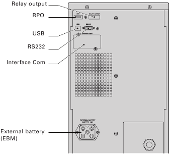
Figure 21. Communication Options and Control Terminals.
Installing Communication Options and Control Terminals
To install the communication options and control terminals:
- Install the appropriate connectivity card and/or necessary cable(s) and connect the cables to the appropriate location. See Figure 21 and the following section, «Communication Options», for detailed information.
- Route and tie the cable(s) out of the way.
- Continue to «Operation» to start up the UPS.
Communication Options
The Eaton 9130 has serial communication capabilities through the USB and RS-232 communication ports or through a connectivity card in the available communication bay.
The UPS supports two serial communication devices according to the following table 7:
| Independent Communication Bay | Multiplexed | |
| USB | RS-232 | |
| Any connectivity card | Available | Not in use |
| Any connectivity card | Not in use | Available |
You can configure relays, signal inputs, and the serial port baud rate through the front panel menus (see table 4). The communication speed of the USB port is fixed at 9600 bps.
RS 232 and USB Communication Ports
To establish communication between the UPS and a computer, connect your computer to one of the UPS communication ports using an appropriate communication cable. See Figure 21 for the communication port locations.
When the communication cable is installed, power management software can exchange data with the UPS. The software polls the UPS for detailed information on the status of the power environment. If a power emergency occurs, the software initiates the saving of all data and an orderly shutdown of the equipment.
The cable pins for the RS 232 communication port are identified in figure 22, and the pin functions are described in Table 8.
.")
Figure 22. RS 232 Communication Port (DB-9 Connector).
Table 8. RS 232 Communication Port Pin Assignment
| Pin Number | Signal Name | Function | Direction from the UPS |
| 1 | DCD | Battery Low signal(1)(3) | Out |
| 2 | RxD | Transmit to external device | Out |
| 3 | TxD | Receive from external device(2) | In |
| 4 | DTR | PnP from external device (tied to Pin 6) | In |
| 5 | GND | Signal common (tied to chassis) | — |
| 6 | DSR | To external device (tied to Pin 4) | Out |
| 7 | RTS | No connection | In |
| 8 | CTS | On Battery signal(1)(3) | Out |
| 9 | RI | +8-12 Vdc power | Out |
(1) Configurable; see the «Relay Configuration» setting in «User Settings».
(2) If Pin 3 receives a Low (+V) signal for ≥ 5 seconds, the UPS executes the command selected by the «Signal Inputs» setting in «User Settings».
(3) When the selected condition is active, output signals on Pins 1 and 8 shift from Low (positive voltage) to High (negative voltage). When the condition no longer exists, the output signal returns to Low.
Connectivity Cards
Connectivity cards allow the UPS to communicate in a variety of networking environments and with different types of devices.
The Eaton 9130 has one available communication bay for the following connectivity cards:
- Connect UPS-MS Web/SNMP Card — has SNMP and HTTP capabilities as well as monitoring through a Web browser interface; connects to Ethernet network. In addition, a Environmental Monitoring Probe can be attached to obtain humidity, temperature, smoke alarm, and security information.
- Relay Interface Card — has isolated dry contact (Form-C) relay outputs for UPS status: Utility failure, Low battery, UPS alarm/OK, or On bypass.
See figure 21 for the location of the communication bay.

Figure 23. Optional Connectivity Cards.
Remote Power-off
RPO is used to shut down the UPS from a distance. This feature can be used for shutting down the load and the UPS by thermal relay, for instance in the event of room over temperature. When RPO is activated, the UPS shuts down the output and all its power converters immediately. The UPS remains on to alarm the fault.
The RPO circuit is an IEC 60950 safety extra low voltage (SELV) circuit. This circuit must be separated from any hazardous voltage circuits by reinforced insulation.
- The RPO must not be connected to any utility connected circuits. Reinforced insulation to the utility is required. The RPO switch must have a minimum rating of 24 Vdc and 20 mA and be a dedicated latching-type switch not tied into any other circuit. The RPO signal must remain active for at least 250 ms for proper operation.
- To ensure the UPS stops supplying power to the load during any mode of operation, the input power must be disconnected from the UPS when the remote power-off function is activated.
Table 9. RPO connections
| RPO Connections | |||
| Wire Function | Terminal Wire Size Rating | Suggested Wire Size | |
| RPO | L1 | 4–0.32 mm² (12–22 AWG) | 0.82 mm² (18 AWG) |
| L2 |
Leave the RPO connector installed in the RPO port on the UPS even if the RPO function is not needed.
Remote control connection and test (see figure 21 for RPO location.)
- Check the UPS is shut down and the electrical supply network disconnected.
- Remove RPO connector from the UPS by unfitting the screws.
- Connect a normally closed volt-free contact between the two pins of connector, see picture 24.

Figure 24.
Contact open: shut down of UPS
To return to normal operation, deactivate the external remote shut down contact and restart the UPS from the front panel. - Plug the RPO connector into the back of the UPS and fix the screws.
- Connect and restart the UPS according to the previously described procedures.
- Activate the external remote shut down contact to test the function.
You can set the RPO polarity. See the «RPO Input Polarity» setting in «User Settings». Depending on user configuration, the pins must be shorted or open to keep the UPS running. To restart the UPS, reconnect (re-open) the RPO connector pins and turn on the UPS manually. Maximum resistance in the shorted loop is 10 ohm. Always test the RPO function before applying your critical load to avoid accidental load loss.
Relay Output Contacts
The UPS incorporates three programmable relay outputs with potential free contacts for remote alarm indications: a standard relay port and two outputs in the RS 232 communication port. See figure 21 for the locations of the ports. An additional four relay outputs can be obtained with the compatible Relay Interface Card. Configure the relay outputs with the «Relay Configuration» setting in «User Settings».
The relay output contacts must not be connected to any utility connected circuits. Reinforced insulation to the utility is required. The relay output contacts have a maximum rating of 30 Vac/1A and 60 Vdc/2A nominal values.
The table 10 shows the options for the relay output contacts.
Table 10. Relay Output Configuration Options
| Relay Signal | Description |
| UPS ok | Activated when the UPS is feeding the load on inverter or on bypass and no alarms are active |
| On Bypass | Activated when the UPS is NOT on bypass operation |
| On Battery | Activated when the UPS operates on battery and the «On Battery Notice Delay» time has expired |
| Battery Low | Activated with the «Battery Low» alarm according to the «Battery Low Alarm» setting |
| Ext. Charger On | Controls an optional external battery charger on and off |
The figure 25 shows the connection of the relay output contacts.

Figure 25. Standard Relay Port Connections.
The figure 26 shows an example where a lamp is connected on the relay output contacts.

Figure 26. Example of Standard Relay Port Connections with lamp.
| Relay signal | L1 | L2 |
| True |  |
 |
| Not true | |
|
| G: external power supply |
Programmable Signal Inputs
The UPS incorporates four programmable signal inputs: one RS 232 input, two connectivity card inputs, and one RPO terminal input. See figure 21 for the locations of the ports. Configure the inputs with the «Signal Inputs» setting in «User Settings».
The table 11 shows the programmable settings for the signal inputs. Table 12 shows the operation logic for the signal inputs.
Table 11. Programmable Signal Inputs
| Signal | Description |
| Not Used | The input operates only as a serial input (RxD) or has no function. |
| Force Bypass | If active, the UPS is forced to static bypass operation regardless of the bypass status. |
| Remote Shutdown | If active, the UPS output turns off after a user-defined remote shutdown delay. The batteries continue charging. Inactive input does not abort the shutdown countdown and does not cause the UPS to start up automatically. |
| Delayed Shutdown (and restart) | If active, the UPS output turns off after a user-defined delayed shutdown delay. The batteries continue charging. Inactive input does not abort the shutdown countdown but will cause the UPS to start up automatically if the input voltage exists. |
| On Generator | If active, synchronization is disabled and the UPS transfers to bypass. |
| Building Alarm 1 | If active, the UPS generates the «Building Alarm 1» alarm. |
Table 12. Polarity Options
| Input | Description |
| High | Active state on high voltage (+Udc) level |
| Low | Active state on low voltage (GND or -Udc) level |
Eaton Power Management Software Suite
Each Eaton 9130 UPS ships with Eaton Power Management Software Suite. To begin installing, see the instructions accompanying the Software Suite CD.
When installing software, select serial port installation. For the UPS manufacturer and model, select Eaton and Eaton 9130. If the Eaton brand options are not available in your version of the software, select Generic UPSs for the manufacturer and Generic XCP for the model.
Eaton software suite provides up-to-date graphics of UPS power and system data and power flow. It also gives you a complete record of critical power events, and it notifies you of important UPS or power information.
If there is a power outage and the Eaton 9130 UPS battery power becomes low, Eaton Sofwtare suite can automatically shut down your computer system to protect your data before the UPS shutdown occurs.
UPS Maintenance
This section explains how to:
- Care for the UPS and batteries
- Replace the UPS internal batteries and Extended Battery Modules (EBMs)
- Test new batteries
- Recycle used batteries or UPS
UPS and Battery Care
For the best preventive maintenance, keep the area around the UPS clean and dust free. If the atmosphere is very dusty, clean the outside of the system with a vacuum cleaner. For full battery life, keep the UPS at an ambient temperature of 25°C (77°F).
If the UPS requires any type of transportation, verify that the UPS is disconnected and turned off and then disconnect the UPS internal battery connector (see figure 28).
The batteries in the UPS are rated for a 3–5 year service life. The length of service life varies, depending on the frequency of usage and ambient temperature. Batteries used beyond expected service life will often have severely reduced runtimes. Replace batteries at least every 5 years to keep units running at peak efficiency.
Storing the UPS and Batteries
If you store the UPS for a long period, recharge the battery every 6 months by connecting the UPS to utility power. The internal batteries charge to 90% capacity in less than 3 hours. However, Eaton recommends that the batteries charge for 48 hours after long-term storage. If optional EBMs are installed, see the recharge times listed in table 24.
Check the battery recharge date on the shipping carton label. If the date has passed and the batteries were never recharged, do not use the UPS. Contact your service representative.
When to Replace Batteries
When the ![]() indicator illuminates, the audible alarm beeps, and the «Battery Needs Service» alarm displays, the batteries may need replacing. Contact your service representative to order new batteries.
indicator illuminates, the audible alarm beeps, and the «Battery Needs Service» alarm displays, the batteries may need replacing. Contact your service representative to order new batteries.
Replacing Batteries
DO NOT DISCONNECT the batteries while the UPS is in Battery mode.
Batteries can be replaced easily without turning the UPS off or disconnecting the load. If you prefer to remove input power to change the batteries, see «UPS Shutdown». Consider all warnings, cautions, and notes before replacing batteries.
- Servicing should be performed by qualified service personnel knowledgeable of batteries and required precautions. Keep unauthorized personnel away from batteries.
- Batteries can present a risk of electrical shock or burn from high short circuit current. Observe the following precautions: 1) Remove watches, rings, or other metal objects; 2) Use tools with insulated handles; 3) Do not lay tools or metal parts on top of batteries, 4) Wear rubber gloves and boots.
- When replacing batteries, replace with the same type and number of batteries or battery packs. Contact your service representative to order new batteries.
- Proper disposal of batteries is required. Refer to your local codes for disposal requirements.
- Never dispose of batteries in a fire. Batteries may explode when exposed to flame.
- Do not open or mutilate the battery or batteries. Released electrolyte is harmful to the skin and eyes and may be extremely toxic.
- Determine if the battery is inadvertently grounded. If inadvertently grounded, remove source from ground. Contact with any part of a grounded battery can result in electrical shock. The likelihood of such shock can be reduced if such grounds are removed during installation and maintenance (applicable to equipment and remote battery supplies not having a grounded supply circuit).
- ELECTRIC ENERGY HAZARD. Do not attempt to alter any battery wiring or connectors. Attempting to alter wiring can cause injury.
- Disconnect charging source prior to connecting or disconnecting battery terminals.
Replacing UPS Internal Batteries
- The UPS internal batteries are heavy. Use caution when handling the heavy batteries.
The internal batteries are located behind the UPS front cover. The internal batteries are packaged together as one unit for easier handling.
To replace the batteries in the UPS:
- Remove the UPS front cover (see figure 27).
To remove the cover:
Remove the 2 fixing screws on the bottom of the cover. Push upon the bottom of the cover and pull the cover toward you to unclip it from the cabinet.A ribbon cable connects the LCD control panel to the UPS. Do not pull on the cable or disconnect it.

Figure 27. Removing the UPS front cover. - Disconnect the internal battery connector (see figure 28).

Figure 28. Disconnecting the UPS internal batteries. - Disconnect one of the 4 battery trays. Remove the plastic protection above the connector and disconnect the battery tray (see figure 29).

Figure 29. Disconnecting the internal battery tray. - Remove the metal fixing part to free the battery tray (see figure 30).

Figure 30. Free the battery tray. - Carefully pull the handle on the battery tray and slide the battery package slowly out onto a flat, stable surface; use two hands to support the battery package. See «Recycling the Used Battery or UPS» for proper disposal.
Verify that the replacement batteries have the same rating as the batteries being replaced. Repeat step 3-4-5 if several battery tray need to be removed.
- Slide the new battery package into the cabinet. Push the battery package in firmly.
- Screw the metal part to fix the battery tray.
Make sure main internal battery connector is disconnected.
- Connect the battery tray and put back the plastic protection above the connector.
A small amount of arcing may occur when connecting the internal batteries. This is normal and will not harm personnel. Connect the cables quickly and firmly.
- Reconnect the internal battery connector. Press the two parts tightly together to ensure a proper connection.
- Place the connector between the screw mounts and reinstall the retained screws.
- Replace the UPS front cover.
To replace the cover, verify that the ribbon cable is protected, then insert the clips on the back of the cover into the cabinet and push firmly to snap the cover into place.
Put back the 2 fixing screws on the bottom of the cover. - Continue to «Testing New Batteries».
Replacing EBMs
The EBM is heavy. Lifting the cabinet into the rack requires a minimum of two people.
To replace the EBMs:
- Unplug the EBM cable from the UPS. If additional EBMs are installed, unplug the EBM cable from the battery connector on each EBM.
- Replace the EBM(s). See «Recycling the Used Battery or UPS» for proper disposal.
A small amount of arcing may occur when connecting an EBM to the UPS. This is normal and will not harm personnel. Insert the EBM cable into the UPS battery connector quickly and firmly.
- Plug the EBM cable(s) into the battery connector(s) as shown in figure 7. Up to four EBMs may be connected to the UPS.
- Verify that the EBM connections are tight and that adequate bend radius and strain relief exist for each cable.
Testing New Batteries
To test new batteries:
- Plug the UPS into a power outlet for 48 hours to charge the batteries.
- Press any button to activate the menu options.
- Select CONTROL then START BATTERY TEST.
The UPS starts a battery test if the batteries are fully charged, the UPS is in Normal mode with no active alarms, and the bypass voltage is acceptable.
During the battery test, the UPS transfers to Battery mode and discharges the batteries for 25 seconds. The front panel displays «Battery test running» and the percentage of the test completed.
Recycling the Used Battery or UPS
Contact your local recycling or hazardous waste center for information on proper disposal of the used battery or UPS.
- Do not dispose of the battery or batteries in a fire. Batteries may explode. Proper disposal of batteries is required. Refer to your local codes for disposal requirements.
- Do not open or mutilate the battery or batteries. Released electrolyte is harmful to the skin and eyes. It may be toxic.
 Do not discard the UPS or the UPS batteries in the trash. This product contains sealed, lead acid batteries and must be disposed of properly. For more information, contact your local recycling/ reuse or hazardous waste center.
 Do not discard waste electrical or electronic equipment (WEEE) in the trash. For proper disposal, contact your local recycling/reuse or hazardous waste center.
Specifications
Model Specifications
This section provides the following specifications:
- Communication options
- Model lists
- Weights and dimensions
- Electrical input and output
- Environmental and safety
- Battery
Table 13. Communication Options
| Communication Bay | (1) available independent communication bay for connectivity cards |
| Compatible Connectivity Cards | Connect UPS-MS Web/SNMP Card Relay Interface Card |
| Communication Ports | RS-232 (DB-9): 1200–9600 bps USB: 9600 bps |
| Signal Inputs | (4) programmable signal inputs (signal and signal return) for indicating building alarms or other use |
| Relay Output Contacts | (1) three-pole connector with (1) contact closure |
Table 14. Extended Battery Module Model List
| EBM Model | Configuration | Battery Voltage | For Power Ratings |
| PW9130N6000T-EBM | Tower | 240 Vdc | 5000–6000 VA |
Table 15. UPS Model List
| Model | Power Level | Rear Panel Diagram |
| PW9130i5000T-XL | 5000 VA / 4500 W | Figure 21 |
| PW9130i6000T-XL | 6000 VA / 5400 W | Figure 21 |
Table 16. Weights and Dimensions
| Model (Tower UPS) | Dimensions (H W D) | Weight |
| PW9130i5000T-XL PW9130i6000T-XL |
575* 242 542 mm (22.64″* 9.53″ 21,34″) | 105 kg (231.5 lb) |
| Model (Tower EBM) | Dimensions (H W D) | Weight |
| PW9130N6000T-EBM | 575* 242 542 mm (22.64″* 9.53″ 21.34″) | 120 kg (264.55 lb) |
Table 17. Electrical Input
| Nominal Frequency | 50/60 Hz auto-sensing |
| Frequency Range | 40–70 Hz before transfer to battery |
| Bypass Voltage Range | +10 / -15% of nominal (default) |
| Noise Filtering | MOVs for normal and common mode noise |
Table 18. Electrical Input
| Model | Default Input (Voltage/Current) | Selectable Input Voltage Range | Voltages at 100% Load |
| PW9130i5000T-XL | 230 V / 21.7 A | 200*, 208*, 220, 230, 240 | 180–276 Vac |
| PW9130i6000T-XL | 230 V / 26.1 A | 200*, 208*, 220, 230, 240 | 180–276 Vac |
208 V are derated by 10%.
Table 19. Electrical Input Connections
| Model | Input Connection | Input Cable |
| PW9130i5000T-XL PW9130i6000T-XL |
Hardwired | None |
Table 20. Electrical Output
| All Models | Normal Mode | Battery Mode |
| Voltage Regulation | ±2 % | Nominal output voltage ±3 % |
| Efficiency | > 98% (High Efficiency mode), > 94 % |
> 92 % |
| Frequency Regulation | Sync with line ±3 Hz of nominal line frequency (outside this range: ±0.1 Hz of auto-selected nominal frequency) | ±0.1 Hz of auto-selected nominal frequency |
| High Voltage Models | ||
| Nominal Outputs | 200/208/220/230/240V (voltage configurable or auto-sensing) 5000/6000 VA 4.5/5.4 kW |
|
| Frequency | 50 or 60 Hz, autosensing or configurable as a frequency converter | |
| Output Overload | 100–102%: Activates Overload alarm (Level 1) 102–129%: Load transfers to Bypass mode after 2 minutes (Level 2) 130–149%: Load transfers to Bypass mode after 30 seconds (Level 3) ≥ 150%: Load transfers to Bypass mode after 100 ms (Level 4) |
|
| Output Overload (Bypass Mode) | 100–109%: Activates Overload alarm (Level 1) 110–129%: UPS shuts down after 5 minutes (Level 2) 130–149%: UPS shuts down after 30 seconds (Level 3) ≥ 150%: UPS shuts down after 300 ms (Level 4) |
|
| Voltage Waveform | Sine wave | |
| Harmonic Distortion | < 3% THD on linear load; < 5% THD on non-linear load |
|
| Transfer Time | Online mode: 0 ms (no break) High Efficiency mode: 10 ms maximum (due to loss of utility) |
|
| Power Factor | 0.9 | |
| Load Crest Factor | 3 to 1 |
Table 21. Electrical Output Connections
| Model | Output Connections | Output Cables |
| PW9130i5000T-XL PW9130i6000T-XL |
Hardwired | None |
Table 22. Environmental and Safety
| Surge Suppression | EN 61000-2-2 EN 61000-4-2, Level 3 EN 61000-4-3, Level 3 EN 61000-4-4, Level 3 (also on signal ports) EN 6100-4-5, Level 3 Criteria A (IEEE C62.41 6 KV) EN 61000-4-6, Level 3 EN 61000-4-8, Level 4 EN 6100-4-11 |
| EMC Certifications | CE per IEC/EN 62040-2, Emissions: Category C2, Immunity: Category C2 |
| EMC (Emissions) | IEC 62040-2:ed2:2005 / EN 62040-2:2006 |
| Safety Conformance | IEC 62040-1-1, IEC 60950-1 |
| Agency Markings | CE |
| Operating Temperature | 0°C to 40°C (32°F to 104°F) in Online mode, with linear derating for altitude NOTE: Thermal protection switches load to Bypass in case of overheating. |
| Storage Temperature | -20°C to 40°C (-4°F to 104°F) with batteries -25°C to 55°C (-13°F to 131°F) without batteries |
| Transit Temperature | -25°C to 55°C (-13°F to 131°F) |
| Relative Humidity | 5–90% noncondensing |
| Operating Altitude | Up to 3,000 meters (9,843 ft) above sea level |
| Transit Altitude | Up to 10,000 meters (32,808 ft) above sea level |
| Audible Noise | < 55 dBA at 1 meter typical |
| Leakage Current | < 1.5 mA |
Table 23. Battery Runtimes (in Minutes) at 100% Load
| Model | Internal Batteries | + 1 EBM | + 2 EBMs | + 3 EBMs | + 4 EBMs |
| PW9130i5000T-XL | 9 min | 41 min | 1 h 19 min | 1 h 57 min | 2 h 42 min |
| PW9130i6000T-XL | 6 min | 32 min | 1 h 03 min | 1 h 37 min | 2 h 08 min |
Note: Battery times are approximate and vary depending on the load configuration and battery charge.
Table 24. Battery
| Internal Batteries | EBMs | |
| Tower Configuration | 5000–6000 VA models: 240 Vdc (20 12 V, 7 Ah) | PW9130N6000T-EBM: 240 Vdc (2 x 20 12 V, 7 Ah) |
| Fuses | 30 A* 2/600 Vdc | 30 A* 2/600 Vdc fuses per EBM |
| Type | Sealed, maintenance-free, valve-regulated, lead-acid, with minimum 3-year float service life at 25°C (77°F) | |
| Monitoring | Advanced monitoring for earlier failure detection and warning | |
| Recharge Time (to 90%) | Internal batteries: 3 hours 1 EBM: 9 hours; 2 EBMs: 15 hours; 3 EBMs: 21 hours; 4 EBMs: 27 hours | |
| Battery Port | External five-pole Banana connector on UPS for connection to EBM | |
| EBM battery cable length | 50 cm |
Troubleshooting
The Eaton 9130 is designed for durable, automatic operation and also alerts you whenever potential operating problems may occur. Usually the alarms shown by the control panel do not mean that the output power is affected. Instead, they are preventive alarms intended to alert the user.
In general:
- Events are silent conditions that are recorded in the Event Log as status information, such as «Clock Set Done».
- Notices are announced by a beep every 5 seconds, recorded in the Event Log, and displayed on the LCD. Examples are «UPS on Battery» and «UPS on Bypass».
- Alarms are announced by a beep every second, recorded in the Event Log, displayed on the LCD, and the Alarm indicator illuminates. Examples are «Output Overload» and «Heatsink Overtemperature».
Use the following troubleshooting chart to determine the UPS alarm condition.
Typical Alarms and Conditions
To check the UPS Status menu for a list of active alarms:
- Press any button on the front panel display to activate the menu options.
- Press the
 button until UPS STATUS displays.
 - Press the Enter button to display the list of active alarms.
To check the Event Log for a history of conditions:
- Press any button on the front panel display to activate the menu options.
- Press the button until EVENT LOG displays.
- Press the Enter button to display the list of conditions.
You can also retrieve the entire Event Log in ASCII format. See «Retrieving the Event Log».
The following table describes typical alarms and conditions.
| Alarm or Condition | Possible Cause | Action |
| On battery LED is on. 1 beep every 5 seconds. |
A utility failure has occurred and the UPS is in Battery mode. | The UPS is powering the equipment with battery power. Prepare your equipment for shutdown. |
| Battery low LED is flashing slowly. 1 beep every second. |
The UPS is in Battery mode and the battery is running low. | This warning is approximate, and the actual time to shutdown may vary significantly. Depending on the UPS load and number of Extended Battery Modules (EBMs), the «Battery Low» warning may occur before the batteries reach 25% capacity. See table 23 for estimated runtimes. |
| On Bypass LED is on. 1 beep every 5 seconds. |
The UPS is in Bypass mode. | The equipment transferred to bypass utility power. Battery mode is not available and your equipment is not protected; however, the utility power continues to be passively filtered by the UPS. Check for one of the following alarms: overtemperature, overload, or UPS failure. |
| Batteries disconnected LED is on. 1 beep every second. |
The UPS does not recognize the internal batteries. | If the condition persists, contact your service representative. |
| The batteries are disconnected. | Verify that all batteries are properly connected. If the condition persists, contact your service representative. | |
| Overload LED is on. 1 beep every second. |
Power requirements exceed the UPS capacity (greater than 100% of nominal) | Remove some of the equipment from the UPS. The UPS continues to operate, but may switch to Bypass mode or shut down if the load increases. The alarm resets when the condition becomes inactive. |
| Overtemperature LED is on. 1 beep every second. |
The UPS internal temperature is too high or a fan has failed. At the warning level, the UPS generates the alarm but remains in the current operating state. If the temperature rises another 10°C, the UPS transfers to Bypass mode or shuts down if bypass is unusable. | If the UPS transferred to Bypass mode, the UPS will return to normal operation when the temperature drops 5°C below the warning level. If the condition persists, shut down the UPS. Clear vents and remove any heat sources. Allow the UPS to cool. Ensure the airflow around the UPS is not restricted. Restart the UPS. If the condition continues to persist, contact your service representative. |
| Battery overvoltage LED is on. 1 beep every second. |
The UPS battery voltage is too high. | The UPS turns off the charger until the next power recycle. Contact your service representative. |
| The UPS does not provide the expected backup time. | The batteries need charging or service. | Apply utility power for 48 hours to charge the batteries. If the condition persists, contact your service representative. |
| Power is not available at the UPS output receptacles. | The UPS is in Standby mode. | Supply power to the connected equipment: press the On/Off button for at least 1 second, until the front panel displays «UPS starting…». |
| The UPS does not start. | The power cord is not connected correctly. | Check the power cord connections. |
| The Remote Power-off (RPO) switch is active or the RPO connector is missing. | If the UPS Status menu displays the «Remote Power Off» notice, inactivate the RPO input. | |
| The UPS operates normally, but some or all of the protected equipment is not on. | The equipment is not connected correctly to the UPS. | Verify that the equipment is plugged into the UPS receptacles. |
| Battery test did not run or was interrupted. | One of the conditions listed in «Running Automatic Battery Tests» was not present. | Resolve the condition, then restart the test. |
| The UPS does not transfer to Bypass mode. | The bypass utility does not qualify. | Check the bypass utility. The UPS is receiving bypass utility power that may be unstable or in brownout conditions. |
| Bypass mode is disabled. | Check that the Bypass settings are configured correctly. See «Configuring Bypass Settings». | |
| USB communication does not work. | The serial port communication speed is set incorrectly for USB. USB requires 9600 bps. | Check that the «Serial Port Configuration» setting is set to 9600 bps. See «User Settings». |
Silencing the Alarm
Press any button on the front panel display to silence the alarm. Check the alarm condition and perform the applicable action to resolve the condition. If the alarm status changes, the alarm beeps again, overriding the previous alarm silencing.
Service and Support
If you have any questions or problems with the UPS, call your Local Distributor or your local service representative and ask for a UPS technical representative.
Please have the following information ready when you call for service:
- Model number
- Serial number
- Firmware version number
- Date of failure or problem
- Symptoms of failure or problem
- Customer return address and contact information
If repair is required, you will be given a Returned Material Authorization (RMA) Number. This number must appear on the outside of the package and on the Bill Of Lading (if applicable). Use the original packaging or request packaging from the Help Desk or distributor. Units damaged in shipment as a result of improper packaging are not covered under warranty. A replacement or repair unit will be shipped, freight prepaid for all warrantied units.
For critical applications, immediate replacement may be available. Call the Help Desk for the dealer or distributor nearest you.
Service and support:
Call your local service representative

Copyright © 2010 EATON
All rights reserved.
Documents / Resources
Download manual
Here you can download full pdf version of manual, it may contain additional safety instructions, warranty information, FCC rules, etc.
Download EATON 9130 UPS Manual
-
Инструкции по эксплуатации
1

EATON Powerware 9130 700 ВА (PW9130i700T-XL) инструкция по эксплуатации
(81 страница)
- Языки:Русский
-
Тип:
PDF -
Размер:
1.62 MB -
Описание:
Батарейный модуль
Просмотр
На NoDevice можно скачать инструкцию по эксплуатации для EATON Powerware 9130 700 ВА (PW9130i700T-XL). Руководство пользователя необходимо для ознакомления с правилами установки и эксплуатации EATON Powerware 9130 700 ВА (PW9130i700T-XL). Инструкции по использованию помогут правильно настроить EATON Powerware 9130 700 ВА (PW9130i700T-XL), исправить ошибки и выявить неполадки.
Этот гайд поможет вам установить и настроить источник бесперебойного питания Eaton 9130. Следуя нашей пошаговой инструкции, вы сможете установить и настроить устройство без необходимости обращаться за помощью к профессионалам.
Хоть источник энергии Eaton 9130 и разработан для использования в малых офисах и домах, некоторые пользователи сталкиваются с проблемами при его настройке и установке. Наш гайд ставит своей целью помочь вам в установке и настройке без стресса и затрат.
Включая легкую настройку и конфигурацию, этот гайд покажет вам, как получить максимальную пользу от вашего источника бесперебойного питания Eaton 9130. Итак, давайте начнем!
Содержание
- Подключение Eaton 9130
- Шаг 1: Подготовьте необходимые инструменты и материалы
- Шаг 2: Подключите батареи
- Шаг 3: Подключите кабель питания
- Шаг 4: Подключите кабель к компьютеру
- Шаг 5: Подключите другие устройства (при необходимости)
- Шаг 1: Распакуйте комплект и проверьте наличие необходимых компонентов
- Шаг 2: Подключите батарею к устройству
- Шаг 2.1: Откройте корпус устройства
- Шаг 2.2: Найдите разъем для батареи
- Шаг 2.3: Подключите батарею к устройству
- Шаг 3: Подключите компьютер к устройству посредством USB-кабеля
- Требования к USB-кабелю
- Подключение компьютера к UPS
- Настройка Eaton 9130
- 1. Подключение к сети и запуск UPS
- 2. Настройка параметров выходного напряжения
- 3. Настройка параметров временной задержки
- 4. Мониторинг и управление
- Шаг 1: Включите устройство и подождите, пока оно запустится
- Шаг 2: Настройте параметры входного напряжения
- 1. Определите тип входного напряжения
- 2. Произведите настройки входного напряжения
- Шаг 3: Настройте переходное время
- 1. Определите параметры переходного времени
- 2. Измените переходное время
- Вопрос-ответ
- Что такое Eaton 9130?
- Как подключить Eaton 9130?
- Как настроить Eaton 9130?
- Как узнать состояние батареи Eaton 9130?
- Как проверить работоспособность Eaton 9130?
- Какие преимущества имеет Eaton 9130 перед другими ИБП?
- Можно ли использовать Eaton 9130 с другими устройствами кроме компьютера?
Подключение Eaton 9130
Шаг 1: Подготовьте необходимые инструменты и материалы
Перед началом подключения Eaton 9130, убедитесь, что у вас есть все необходимые инструменты и материалы:
- Кабель питания Eaton 9130
- Кабель подключения к компьютеру
- Отвертка
- Инструкция пользователя
Шаг 2: Подключите батареи
Перед подключением Eaton 9130 убедитесь, что батареи в нем установлены. Следующим шагом необходимо подключить батареи к устройству.
Шаг 3: Подключите кабель питания
Подключите кабель питания к Eaton 9130 и сетевому розетке. Убедитесь, что кабель питания надежно закреплен.
Шаг 4: Подключите кабель к компьютеру
Подключите кабель к компьютеру и убедитесь, что он надежно закреплен. Кабель должен быть подключен к порту USB на задней панели устройства.
Шаг 5: Подключите другие устройства (при необходимости)
Если вам необходимо подключить другие устройства, такие как принтер или модем, выполните соответствующие действия. Обычно порты для таких устройств находятся на задней панели Eaton 9130.
После выполнения всех этих шагов, вы можете включить Eaton 9130 и начать его настройку.
Шаг 1: Распакуйте комплект и проверьте наличие необходимых компонентов
Перед началом настройки Eaton 9130 необходимо убедиться, что в комплекте присутствуют все необходимые компоненты:
- UPS Eaton 9130
- Кабель питания
- Кабель USB или последовательный кабель (зависит от модели и интерфейса подключения)
- CD с драйверами и программным обеспечением
- Инструкция по эксплуатации
Если каких-то компонентов не хватает или они повреждены, необходимо связаться с продавцом или производителем для их замены.
После проверки наличия компонентов можно перейти к следующему шагу настройки.
Шаг 2: Подключите батарею к устройству
Шаг 2.1: Откройте корпус устройства
Перед тем, как подключать батарею, нужно открыть корпус устройства. Для этого необходимо найти защелку на задней панели. Потянув за эту защелку, можно открыть корпус.
Шаг 2.2: Найдите разъем для батареи
После открытия корпуса, нужно найти разъем для батареи. Обычно он расположен в центре корпуса и выглядит как разъем для зарядки лэптопа. Если разъем не найден, следует обратиться к инструкции производителя устройства.
Шаг 2.3: Подключите батарею к устройству
Найдите кабель от батареи с двумя разъемами – один разъем для устройства, другой – для батареи. Подключите разъемы к соответствующим местам в устройстве и батарее. Для удобства разъемы часто окрашены в разные цвета.
Можно закрепить батарею на специальной держателе, чтобы она не двигалась и не мешала работе устройства. Если предусмотрено подключение нескольких батарей, подключите их также по инструкции производителя.
Шаг 3: Подключите компьютер к устройству посредством USB-кабеля
Требования к USB-кабелю
Для подключения компьютера к UPS необходим USB-кабель типа A/B. Кабель должен соответствовать установленному в комплекте кабелю.
Подключение компьютера к UPS
- Соедините USB-разъем на задней панели UPS с USB-портом на компьютере при помощи USB-кабеля.
- Должен появиться звуковой сигнал, который подтвердит подключение компьютера к UPS.
- Система компьютера определит устройство, и вы увидите сообщение о том, что USB-устройство для Электропитания готово к использованию.
После подключения компьютера к UPS можно переходить к настройке питания UPS.
Настройка Eaton 9130
1. Подключение к сети и запуск UPS
Перед началом настройки необходимо правильно подключить Eaton 9130 к сети. Вставьте штекер в розетку и нажмите кнопку включения на передней панели UPS. Проверьте, что на дисплее появилось сообщение о работе.
2. Настройка параметров выходного напряжения
Для настройки параметров выходного напряжения следует зайти в меню кнопками на передней панели. Выберите пункт «Output» и установите необходимые параметры. Обычно настроенное напряжение равно напряжению в сети.
3. Настройка параметров временной задержки
Зайдите в меню, выберите пункт «Delay» и установите необходимое время задержки. Обычно время задержки необходимо для того, чтобы Eaton 9130 мог пройти проверку системы и переключиться на работу от батареи в случае отключения электричества.
4. Мониторинг и управление
За настройкой Eaton 9130 можно следить через программу Intelligent Power Manager, которая позволяет контролировать состояние UPS и изменять его параметры удаленно. Также с помощью этой программы можно настроить уведомления о событиях, связанных с работой UPS.
Шаг 1: Включите устройство и подождите, пока оно запустится
Первый шаг в настройке Eaton 9130 — правильное включение устройства. Сначала убедитесь, что все кабели подключены к правильным портам. После этого включите устройство, нажав кнопку питания на передней панели.
Когда устройство включится, позвольте ему запуститься полностью и инициализироваться. Это может занять несколько минут, так что не прерывайте процесс. Вы можете узнать, когда устройство готово к использованию, по нескольким световым индикаторам на передней панели.
Помните, что при первом включении устройства, вам может потребоваться выполнять некоторые базовые настройки, прежде чем вы сможете начать использовать его для своих нужд. Обратитесь к руководству пользователя, чтобы узнать, как выполнить эти настройки и продолжить настройку устройства.
Шаг 2: Настройте параметры входного напряжения
1. Определите тип входного напряжения
Перед тем как начать настраивать входное напряжение, необходимо убедиться, что вы правильно определили тип входного напряжения. Eaton 9130 имеет возможность работать с разными типами напряжения: однофазное (220 В) или трехфазное (380/400/415 В).
Вы можете проверить, какой тип напряжения доступен, подключив Eaton 9130 к источнику электропитания и проверив данные на дисплее.
2. Произведите настройки входного напряжения
Для выполнения настроек входного напряжения необходимо зайти в меню «Input Settings» на дисплее Eaton 9130. В этом меню вы можете произвести следующие настройки:
- «Output Nominal Voltage»: настройка номинального напряжения. Определите соответствующее значение в зависимости от типа электропитания.
- «Input Voltage Range»: настройка диапазона входного напряжения. Задайте значения, соответствующие параметрам вашего источника электропитания.
- «Low Mains Sensitivity»: настройка чувствительности при низком уровне напряжения. Обычно значение устанавливается на 160 В для защиты оборудования от скачков напряжения.
- «High Mains Sensitivity»: настройка чувствительности при высоком уровне напряжения.
- «Frequency»: настройка частоты электрической сети. Задайте соответствующее значение для вашего региона.
После завершения настроек необходимо сохранить изменения и перезапустить Eaton 9130 для применения настроек.
Шаг 3: Настройте переходное время
1. Определите параметры переходного времени
Переходное время (transition time) определяет максимальное время, которое устройство может работать от батареи в случае сбоя электропитания. По умолчанию это значение установлено на 4 минуты, однако, у вас есть возможность изменить это время в зависимости от ваших требований.
2. Измените переходное время
Для изменения переходного времени выполните следующие действия:
- Откройте веб-интерфейс устройства, используя указанный в инструкции IP-адрес;
- Введите логин и пароль (по умолчанию логин – admin, пароль – 123456789);
- Выберите вкладку «Configuration» и откройте раздел «System Settings»;
- В поле «Output Relay…» выберите «None»;
- В поле «Transition Time» установите желаемое значение и сохраните изменения, нажав кнопку «Apply».
Теперь вы успешно настроили переходное время в Eaton 9130 и можете быть уверены в том, что ваше оборудование будет работать даже при сбое в электропитании.
Вопрос-ответ
Что такое Eaton 9130?
Eaton 9130 представляет собой источник бесперебойного питания (ИБП) с двойным преобразованием. Он защищает оборудование от сбоев в сети, снижает риск потери данных и повреждения оборудования в результате неожиданных отключений питания.
Как подключить Eaton 9130?
Для подключения Eaton 9130 к компьютеру или другому устройству необходимо использовать кабель USB или последовательный кабель RS-232, в зависимости от типа подключения. Подробная инструкция по подключению будет зависеть от конфигурации системы и настроек оборудования.
Как настроить Eaton 9130?
Настройка Eaton 9130 зависит от требований системы. Обычно процесс может быть выполнен через веб-интерфейс ИБП, используя специальное программное обеспечение. Некоторые модели могут быть настроены через кнопки на передней панели. Пожалуйста, обратитесь к руководству пользователя, чтобы получить подробную инструкцию по настройке.
Как узнать состояние батареи Eaton 9130?
В зависимости от модели, информация о состоянии батареи может быть отображена на передней панели, в приложении управления ИБП или через веб-интерфейс. Определенное количество светодиодов или символов на дисплее указывает процент заряда батареи в режиме работы от аккумуляторов.
Как проверить работоспособность Eaton 9130?
Для проверки работоспособности ИБП Eaton 9130 необходимо выполнить автотест, который проверяет внутренние компоненты. Для этого можно использовать специальное программное обеспечение, которое поставляется вместе с оборудованием. Подробная инструкция по выполнению автотеста может также быть найдена в руководстве пользователя.
Какие преимущества имеет Eaton 9130 перед другими ИБП?
Eaton 9130 имеет несколько преимуществ перед другими ИБП, включая: двойное преобразование, безопасный режим замены батареи, возможность горячей замены батарей, функцию автоматического регулирования напряжения и низкое энергопотребление в режиме ожидания.
Можно ли использовать Eaton 9130 с другими устройствами кроме компьютера?
Да, Eaton 9130 может быть использован с любыми устройствами, которые требуют безопасного и стабильного источника питания. Некоторые из них могут включать сервера, хранилища данных, сетевое оборудование, коммуникационное оборудование, медицинское оборудование и т.д.
Powerware Series ИБП Eaton 9130 700–3000 BA Руководство пользователя ®
Сведения об оборудовании Класса A EMC (Низковольтные модели более 1500 ВА) FCC, Часть 15 ПРИМЕЧАНИЕ это оборудование прошло тестирование и признано соответствующим предельным характеристикам цифровых устройств Класса A согласно части15 Правил FCC. Эти предельные характеристики предназначены для
Сведения об оборудовании Класса B EMC (Низковольтные модели до 1500 ВА и Высоковольтные модели до 3000 ВА) FCC Раздел 15 ПРИМЕЧАНИЕ Это оборудование прошло тестирование и признано соответствующим предельным характеристикам цифровых устройств Класса В, согласно части 15 Правил FCC. Эти предельные
Как получить Декларацию о соответствии Изделия со знаком CE соответствуют следующим стандартам и директивам ЕС: S Гармонизированные стандарты: IEC 61000-3-12 S Директивы ЕС: 73/23/EEC, Директива Совета по оборудованию, предназначенному для эксплуатации в определенных пределах напряжения 93/68/EEC,
Ñîäåðæàíèå 1 Введение . . . . . . . . . . . . . . . . . . . . . . . . . . . . . . . . . . . . . . . . . . . . . . . . . . . . . . . 7 2 Ïðåäóïðåæäåíèÿ ïî ìåðàì áåçîïàñíîñòè . . . . . . . . . . . . . . . . . . . . . . . 9 3 Установка . . . . . . . . . . . . . . . . . . . . . . . . . . . . . . . . .
Ñîäåðæàíèå 6 7 8 6 Работа модема . . . . . . . . . . . . . . . . . . . . . . . . . . . . . . . . . . . . . . . . . . . . . . . . . . . . . . . . . . . . . . . . . Программа управления питанием LanSafe . . . . . . . . . . . . . . . . . . . . . . . . . . . . . . . . . . . . . . . . 44 45 Обслуживание
Глава 1 Введение Источник Eaton® 9130 бесперебойного питания (ИБП) серии Powerware защищает чувствительное электронное оборудование от наиболее распространенных проблем питания, включая отключение питания сети, проседания напряжения, скачки напряжения, снижение нагрузки, электрические помехи в сети
Введение Ðèñóíîê 2. Eaton 9130 Установка в стойку EBM Ðèñóíîê 3 показывает Eaton 9130 ИБП типа башня и дополнительный EBM. Ðèñóíîê 3. ИБП Eaton 9130 типа башня и EBM (показаны модели 2000-3000 ВА) 8 Ðóêîâîäñòâî ïîëüçîâàòåëÿ ÈÁÏ Eaton® 9130 (700–3000 BA) S 164201941806 Rev 1
Ãëàâà 2 Ïðåäóïðåæäåíèÿ ïî ìåðàì áåçîïàñíîñòè ÂÀÆÍÛÅ ÓÊÀÇÀÍÈß ÏÎ ÌÅÐÀÌ ÁÅÇÎÏÀÑÍÎÑÒÈ ÑÎÕÐÀÍÈÒÅ ÝÒÈ ÓÊÀÇÀÍÈß Â äàííîì ðóêîâîäñòâå ñîäåðæàòñÿ âàæíûå èíñòðóêöèè ïî óñòàíîâêå è îáñëóæèâàíèþ èñòî÷íèêà áåñïåðåáîéíîãî ïèòàíèÿ (ÈÁÏ) è áàòàðåé. Ïåðåä ðàáîòîé ñ îáîðóäîâàíèåì ïðî÷òèòå âñå èíñòðóêöèè. Ñîõðàíèòå
Ïðåäóïðåæäåíèÿ ïî ìåðàì áåçîïàñíîñòè ÎÑÒÎÐÎÆÍÎ S Âûñîêîå íàïðÿæåíèå, âûçâàííîå êîðîòêèì çàìûêàíèåì â áàòàðåå, ìîæåò ïðèâåñòè ê ïîðàæåíèþ ýëåêòðè÷åñêèì òîêîì èëè îæîãó. Ñîáëþäàéòå ìåðû ïðåäîñòîðîæíîñòè. Òåõíè÷åñêîå îáñëóæèâàíèå äîëæíî îñóùåñòâëÿòüñÿ êâàëèôèöèðîâàííûì ïåðñîíàëîì ïî ðàáîòå ñ
Глава 3 Установка В этой главе рассматриваются: S Осмотр оборудования S Распаковка шкафа S Проверка комплекта принадлежностей S Установка корпуса (для монтажа в стойку и типа башня) S Проводка S Первоначальный запуск Осмотр оборудования Если какое-либо оборудование было повреждено при
Установка Проверка комплекта принадлежностей Убедитесь, что в комплект ИБП входят следующие компоненты: S Руководство пользователя ИБП S Инструкции по быстрому вводу в эксплуатацию S Компакт-диск с комплектом программ S Кабель USB S Шнур питания (для моделей без фиксированного шнура питания) Если
Установка Необходимые инструменты Для монтажа деталей могут понадобиться следующие инструменты: S Плоская отвертка среднего размера S Крестообразная Phillips® #2 S Рожковый или накидной ключ 7 и 8 мм Вариант установки в стойке ÎÑÒÎÐÎÆÍÎ S Шкаф тяжелый (см. страницу 58). Для выемки шкафа из ящика
Установка 2. Выберите надлежащие отверстия в направляющих полозьях для размещения ИБП в стойке (см. Ðèñóíîê 5). Направляющие занимают четыре места в передней и задней части стойки. 3. Прикрепите узел одной направляющей к передней части стойки при помощи одного винта с потайной головкой M6 x 16 и
Установка ÏÐÈÌÅ×ÀÍÈÅ. На каждой стороне ИБП находится по две группы из четырех крепежных отверстий, соответствующих: Выдвинутому вперед положению и среднему положению. Выберите положение, которое соответствует потребностям вашей конфигурации. Монтажная скоба Винты M4 x 8 с плоской головкой (4
Установка 14. Перейдите к следующему разделу «Монтаж проводки в стойке». Задний упорный угольник Винты с потайной головкой М3 x 8 Ðèñóíîê 8. Крепление задней части корпуса (по выбору) Монтаж проводки в стойке В этой главе рассматриваются: S Установка ИБП, включая подсоединение внутренних батарей
Установка ÎÑÒÎÐÎÆÍÎ При подключении внутренних батарей может возникнуть незначительное искрение. Это нормально и не опасно для персонала. Быстро и надежно подключите кабели. 2. Подсоедините разъем внутренней батареи (см. Ðèñóíîê 10). Модели до 1500 ВА. Отсоедините самый правый верхний белый разъем
Установка Подключение EBM Для установки дполнительного (ых) EBM для ИБП: 1. В нижней части правой передней крышки ИБП снимите EBM кабельную заглушку (см. Ðèñóíîê 11). ÏÐÈÌÅ×ÀÍÈÅ. Берегите панель управления ЖКЭ и подключенный плоский кабель от повреждений. esc Выемка для EBM кабелей Ðèñóíîê 11.
Установка 4. Если вы устанавливаете несколько EBM, для каждого дополнительного EBM снимите кабельную заглушку EBM в верхней и нижней части передней крышки EBM. Расположение кабельных заглушек Ðèñóíîê 12 см. на EBM. ÎÑÒÎÐÎÆÍÎ При подключении EBM к ИБП может возникнуть незначительное искрение. Это
Установка Установка в виде башни Шкаф в Eaton 9130 виде башни поставляется в полностью собранном виде, готовом к подключению. ÎÑÒÎÐÎÆÍÎ Шкаф тяжелый (см. страницу 58). Для выемки шкафа из ящика требуется минимум два человека. Для установки корпуса: 1. Поместите ИБП на ровную, устойчивую
Установка ПРИМЕЧАНИЕ Оставьте плоский кабель присоединенным. Ðèñóíîê 14. Снятие передней крышки ИБП ÎÑÒÎÐÎÆÍÎ При подключении внутренних батарей может возникнуть незначительное искрение. Это нормально и не опасно для персонала. Быстро и надежно подключите кабели. 2. Подсоедините разъем внутренней
Установка 5. Установите на место переднюю крышку ИБП. Чтобы заменить крышку, убедитесь в том, что плоский кабель имеет соответствующую защиту, а затем вставьте фиксаторы на задней стороне крышки в отсек и нажмите крышку до щелчка, чтобы она встала на место. 6. При установке программы управления
Установка Снимите держатель кабеля. Установите держатель кабеля на место. Подключите кабель EBM. Поверните держатель. 1000–1500 ВА Модели 2000–3000 ВА Модели Ðèñóíîê 16. Подключение EBM Первый запуск ИБП Для запуска ИБП: ÏÐÈÌÅ×ÀÍÈÅ. Убедитесь, что общая паспортная мощность потребителей не превышает
Установка 2. Если установлены дополнительные EBM, убедитесь в EBM том. что они подключены к ИБП. Модели для монтажа в стойку. См. раздел «Подключение EBM» на стр. 18. Модели типа башня. См. раздел «Подключение EBM» на стр. 22. 3. Включите оборудование, которое необходимо предохранить от скачков
Установка ÏÐÈÌÅ×ÀÍÈÅ. Eaton рекомендует настроить дату и время. ÏÐÈÌÅ×ÀÍÈÅ. При первоначальной настройке, ИБП настраивает частоту системы в соответствии с частотой питающей линии (функция автоматического определения входной частоты включена по умолчанию). По окончании первоначальной настройки,
Глава 4 Эксплуатация В данном разделе содержится информация о работе с ИБП Eaton 9130, включая работу с панелью управления, рабочие режимы, включение и выключение ИБП, переключение режимов ИБП, просмотр журнала событий, настройку параметров питания, а также настройку параметров байпаса, сегментов
Эксплуатация Изменение языка Нажмите и удерживайте первую кнопку слева в течение примерно трех секунд, чтобы выбрать меню языков. Это действие можно выполнить из любого состояния экрана меню ЖКД. Функции дисплея По истечении 15 минут, при отсутствии активности, на ЖКД по умолчанию появляется
Эксплуатация Пользовательские настройки Òàáëèöà 3 показывает параметры, которые могут быть изменены пользователем. Òàáëèöà 3. Пользовательские настройки Описание Доступные настройки Настройка по умолчанию Изменить язык [Английский] [Французский] [Испанский] [Немецкий] [Русский] Меню, сообщения о
Эксплуатация Òàáëèöà 3. Пользовательские настройки (продолжение) Описание Доступные настройки Настройка по умолчанию Переход на байпас в случае перегрузки* [Немедленно] [С задержкой] При немедленном переходе, переход происходит при нагрузке >102 %. Переход с задержкой осуществляется в соответствии
Эксплуатация Òàáëèöà 3. Пользовательские настройки (продолжение) Описание Доступные настройки Настройка по умолчанию Количество комплектов батарей [0] [1] [2] … [10] См. раздел «Установка ИБП для ЕВМ» на стр. 37. 1 Режим зарядки батареи [Последовательное переключение ABM] [Постоянно]
Эксплуатация Режим работы от батарей При работе ИБП во время отключения питания сети, звуковой сигнал подается каждые пять секунд, а индикаторы горят непрерывно. Когда электроэнергия включается вновь, ИБП переходит в режим обычной работы и начинает заряжать батареи. становится низким, то Если, в
Эксплуатация В случае сбоя питания от сети в режиме ожидания, логический источник питания выключается примерно через 10 секунд. Если происходит сбой питания от сети в то время, как ИБП находится в ожидании команд, устройство и источник питания логики ИБП отключаются приблизительно через 30 секунд.
Эксплуатация Запуск ИБП от батареи ÏÐÈÌÅ×ÀÍÈÅ. Перед тем, как воспользоваться этой функцией, необходимо обеспечить подачу питание на ИБп от сети, включив выход, по крайней мере, один раз. ÏÐÈÌÅ×ÀÍÈÅ. Запуск от батареи можно отключить. См. Запуск от батареи в разделе «Пользовательские настройки» на
Эксплуатация Просмотр журнала событий Для просмотра журнала событий с дисплея: 1. Откройте параметры меню нажатием любой кнопки, а затем выберите ЖУРНАЛ СОБЫТИЙ. 2. Просмотрите зарегистрированные события. Для получения журнала событий через последовательный порт: 1. С коммуникационного устройства,
Эксплуатация Верхнее предельное значение напряжения байпаса. По умолчанию переход на байпас отменяется в том случае, если измеренный уровень напряжения на байпасе выше номинального выходного напряжения плюс 10 %. Можно установить настройку другого процентного значения от номинального напряжения.
Эксплуатация Для управления сегментами нагрузки с дисплея: 1. Откройте параметры меню нажатием любой кнопки, а затем выберите УПРАВЛЕНИЕ и СЕГМЕНТЫ НАГРУЗКИ. 2. установите для нужного сегмента нагрузки состояние ВКЛ. или ВЫКЛ. и нажмите ВВОД для подтверждения. 3. Настройте другой сегмент нагрузки,
Эксплуатация Настройки батареи Укажите для ИБП количество установленных, для автоматического выполнения проверок батареи и настройки автоматического сброса EBM. Конфигурирование ИБП для EBM Для обеспечения максимального времени работы батарей сконфигурируйте ИБП на правильное количество EBM: 1.
Эксплуатация Конфигурирование автоматического перезапуска ИБП автоматически перезапускается в случае, если в сети вновь появляется ток после того, как выход ИБП был выключен ввиду разрядки батарей, входного сигнала выключения или автоматической команды выключения. Можно задать сегменту нагрузки
Раздел 5 Коммуникация В данном разделе рассматривается: S Коммуникационные порты (RS-232 и USB) S Коммуникационные карты S Дистанционное аварийное отключение (REPO) S Релейные выходные контакты S Программируемые сигнальные входы S Работа модема S Программа управления питанием LanSafe® Ðèñóíîê 18
Коммуникация Коммуникационные опции Осуществляет функции связи через коммуникационные порты USB и RS-232 или с помощью карты связи в Eaton 9130 соответствующем отсеке. ИБП поддерживает работу двух устройств по последовательному каналу в соответствии со следующей таблицей: Мультиплексированное
Коммуникация Òàáëèöà 4. Назначение контактов коммуникационного порта Номер контакта Название сигнала Функция Указания ИБП 1 DCD Сигнал низкого уровня заряда батареи1,3 Выход 2 RxD Передача на внешнее устройство Выход 3 TxD Получение с внешнего устройства2 Вход 4 DTR PnP с внешнего устройства
Коммуникация Дистанционное аварийное отключение Дистанционное аварийное отключение (REPO) используется для выключения ИБП на расстоянии. Эту функцию можно использовать для выключения потребителя и ИБП при помощи теплового реле, например, в случае перегрева помещения. При включенной функции REPO,
Коммуникация ÏÐÈÌÅ×ÀÍÈÅ. В зависимости от пользовательской настройки, контакты необходимо закоротить или открыть для работы ИБП. Для перезапуска ИБП вновь соедините контакты разъема REPO и включите ИБП вручную. Максимальное сопротивление в закороченном контуре составляет 10 Ом. ÏÐÈÌÅ×ÀÍÈÅ.
Коммуникация Программируемые сигнальные входы ИБП имеет четыре программируемых сигнальных входа: один вход RS-232, два входа для коммуникационных карт и один входной разъем REPO. Расположение портов см. на Ðèñóíîê 18 на странице 39. Настройте четыре входа с помощью настройки «Сигнальные входы» в
Коммуникация Программа управления питанием LanSafe Каждый ИБП Eaton 9130 поставляется в комплекте с Программа управления питанием LanSafe. Чтобы начать установку Программа управления питанием LanSafe, см. инструкции, прилагаемые к Компакт-диск с комплектом программ. ÏÐÈÌÅ×ÀÍÈÅ. При установке
Раздел 6 Обслуживание ИБП В этом разделе поясняются: S Уход за ИБП и батареями S Заменить внутренние батареи ИБП Внешний батарейный модуль и EBM S Тестирование новых батарей S Утилизация использованных батарей и ИБП S Обновить программно-аппаратное обеспечение ИБП Уход за ИБП и батареями Для
Обслуживание ИБП Если вы предпочитаете отключать входное питание для замены батарей, см. «Выключение ИБП» на странице 33. Перед заменой батарей учтите все предупреждения и примечания. ÏÐÅÄÓÏÐÅÆÄÅÍÈÅ S Обслуживание должно проводиться квалифицированным персоналом, хорошо знающим батареи и меры
Обслуживание ИБП ПРИМЕЧАНИЕ Оставьте плоский кабель присоединенным. Ðèñóíîê 23. Снятие правой передней крышки ИБП 2. Отсоедините разъем внутренней батареи (см. Ðèñóíîê 24). 3. Только для моделей до 1500 ВА. Если кабель EBM не подключен к EBM, отсоедините EBM кабель и переместите его влево (см.
Обслуживание ИБП ÎÑÒÎÐÎÆÍÎ При подключении внутренних батарей может возникнуть незначительное искрение. Это нормально и не опасно для персонала. Быстро и надежно подключите кабели. 8. Снова подсоедините разъем внутренней батареи. Подсоединяйте красное к красному, а черное к черному. Нажмите на обе
Обслуживание ИБП 2. Удалите и отложите в сторону два винта, удерживающие разъем внутренней батареи. Отсоедините разъем внутренней батареи. См. Ðèñóíîê 26. Разъем внутренней батареи Крышка батареи Рукоятка батарейного отсека Ðèñóíîê 26. Замена внутренних батарей ИБП 3. Удалите и отложите в сторону
Обслуживание ИБП 9. Установите на место переднюю крышку ИБП. Чтобы заменить крышку, убедитесь в том, что плоский кабель имеет соответствующую защиту, а затем вставьте фиксаторы на задней стороне крышки в отсек и нажмите крышку до щелчка, чтобы она встала на место. 10. Перейдите к следующему
Обслуживание ИБП 5. Снимите переднюю крышку каждого нового EBM (см. Ðèñóíîê 27). Удалите крышку, выкрутите и сохраните два винта, с правой стороны этой крышки. Возьмитесь за края крышки и сдвиньте ее влево, а затем в направлении от шкафа. 6. Для нижней части (или только) EBM снимите кабельную
Обслуживание ИБП ÎÑÒÎÐÎÆÍÎ При подключении EBM к ИБП может возникнуть незначительное искрение. Это нормально и не опасно для персонала. Вставляйте кабель EBM в разъем батарей ИБП быстро и прочно. 4. Подключите кабели EBM к разъему батареи, как показано Ðèñóíîê 16 на стр. 23. К ИБП может быть
Обслуживание ИБП Обновление программно-аппаратного обеспечения ИБП Для получения последних обновлений программно-аппаратного обеспечения ИБП, регулярно посещайте веб-сайт www.eaton.com/powerquality. Оттуда можно загрузить последнюю версию программно-аппаратного обеспечения и указания по его
Глава 7 Технические характеристики Технические характеристики моделей В данной главе указаны следующие технические характеристики: S Коммуникационные опции S Списки моделей S Вес и размеры S Электрические параметры входа и выхода S Экологические параметры и параметры безопасности S Батарея Òàáëèöà
Технические характеристики Òàáëèöà 10. Список моделей ИБП (модели для монтажа в стойку) Модель Уровень мощности Схема задней панели PW9130L700R-XL2U 700 BA / 630 Bт Ðèñóíîê 28 на стр. 69 PW9130L1000R-XL2U 1000 BA / 900 Bт Ðèñóíîê 28 на стр. 69 PW9130L1500R-XL2U 1500 BA / 1350 Bт Ðèñóíîê 33 на стр.
Технические характеристики Òàáëèöà 11. Список моделей ИБП (модели типа «башня») Модель Уровень мощности Схема задней панели PW9130L700T-XL 700 BA / 630 Bт Ðèñóíîê 43 на стр. 73 PW9130L1000T-XL 1000 BA / 900 Bт Ðèñóíîê 44 на стр. 73 PW9130L1500T-XL 1500 BA / 1350 Bт Ðèñóíîê 45 на стр. 73
Технические характеристики Òàáëèöà 12. Вес и размеры (модели для монтажа в стойку) Модель (ИБП для монтажа в стойку) Размеры (В x Ш x Г) Вес PW9130L700R-XL2U PW9130L1000R-XL2U PW9130G1000R-XL2U PW9130i1000R-XL2U PW9130G1000R-XL2UEU PW9130G1000R-XL2UAU 86,5 x 438 x 430 мм 16,0 кг PW9130L1500R-XL2U
Технические характеристики Òàáëèöà 13. Вес и габаритные размеры (модели типа «башня») Модель (ИБП типа «башня») Размеры (В xШ xГ) Вес PW9130L700T-XL PW9130i700T-XL PW9130G700T-XLAU 231* x 60 x 354 мм 12,2 кг PW9130L1000T-XL PW9130G1000T-XL PW9130i1000T-XL PW9130G1000T-XLEU PW9130G1000T-XLAU 231* x
Технические характеристики Òàáëèöà 15. Входные электрические параметры (модели для монтажа в стойку) Входные параметры по умолчанию (напряжение/ток) Регулируемые значения входного напряжения Диапазон напряжения при 100 % нагрузке PW9130L700R-XL2U 120V / 5,8A 100*, 110**, 120, 127 80–138 В перем.
Технические характеристики Òàáëèöà 16. Входные электрические параметры (модели типа «башня») Входные параметры по умолчанию (напряжение/ток) Регулируемые значения входного напряжения Диапазон напряжения при 100 % нагрузке PW9130L700T-XL 120V / 5,8A 100*, 110**, 120, 127 80–138 В перем. тока
Технические характеристики Òàáëèöà 17. Электрические входные соединения (модели для монтажа в стойку) Модель Входное подключение Входной кабель PW9130L700R-XL2U 5-15P Присоединяемый кабель PW9130L1000R-XL2U 5-15P Присоединяемый кабель PW9130L1500R-XL2U 5-15P Присоединяемый кабель PW9130L2000R-XL2U
Технические характеристики Òàáëèöà 18. Электрические входные соединения (модели типа «башня») Модель Входное подключение Входной кабель PW9130L700T-XL 5-15P Присоединяемый кабель PW9130L1000T-XL 5-15P Присоединяемый кабель PW9130L1500T-XL 5-15P Присоединяемый кабель PW9130L2000T-XL 5-20P
Технические характеристики Òàáëèöà 19. Выходные электрические параметры (все модели) Все модели Нормальный режим Режим работы от батарей ±2% Номинальное выходное напряжение ± 3 % Кпд > 95 % (в режиме высокой эффективности), > 88 % > 79,5 % (700 VA), > 82 % (1000–1500 VA), > 84 % (2000–3000 VA)
Технические характеристики Òàáëèöà 20. Электрические выходные соединения (модели для монтажа в стойку) Модель Выходные соединения Выходные кабели PW9130L700R-XL2U (6) 5-15R Нет PW9130L1000R-XL2U (6) 5-15R Нет PW9130L1500R-XL2U (6) 5-15R Нет PW9130L2000R-XL2U (1) L5-20R, (6) 5-20T Нет
Технические характеристики Òàáëèöà 21. Электрические выходные соединения (модели типа «башня») Модель Выходные соединения Выходные кабели PW9130L700T-XL (6) 5-15R Нет PW9130L1000T-XL (6) 5-15R Нет PW9130L1500T-XL (6) 5-15R Нет PW9130L2000T-XL (1) L5-20R, (4) 5-20T Нет PW9130L3000T-XL (1) L5-30R,
Технические характеристики Òàáëèöà 22. Экологические показатели и показатели безопасности (Все модели) 120 Модели В перем. тока 208/230/240 Модели В перем. тока Подавление импульсов напряжения переходных процессов ANSI C62.41 Категория B3 (6 блок кольцевой цепи КВ и комбинация) EN 61000-2-2 EN
Технические характеристики Òàáëèöà 23. Время работы от батарей (в минутах) при 100 % нагрузке (модели для монтажа в стойку) Модель Внутренние батареи + 1 EBM + 2 EBMS + 3 EBMS + 4 EBMS PW9130L700R-XL2U 9 41 72 105 130 PW9130L1000R-XL2U 5 30 55 83 108 PW9130G1000R-XL2U PW9130i1000R-XL2U
Технические характеристики Òàáëèöà 25. Батарея Внутренние батареи EBM Стоечная конфигурация 700–1000 Модели ВА: 36 В пост. тока (3 12 В, 9 Ач) 1500 Модели ВА: 48 В пост. тока (3 12 В, 9 Ач) 2000–3000 Модели ВА: 72 В пост. тока (3 12 В, 9 Ач) PW9130N1000R-EBM2U: 36 Vdc (2×3 12V, 9 Ah)
Технические характеристики Ðèñóíîê 30. Модели PW9130i1000R-XL2U, PW9130G1000R-XL2UEU Ðèñóíîê 31. Модель PW9130G1000R-XL2UAU Ðèñóíîê 32. Модель PW9130G1500R-XL2UAU Ðèñóíîê 33. Модель PW9130L1500R-XL2U Ðèñóíîê 34. Модель PW9130i1500R-XL2U 70 Ðóêîâîäñòâî ïîëüçîâàòåëÿ ÈÁÏ Eaton® 9130 (700–3000 BA) S
Технические характеристики Ðèñóíîê 35. Модель PW9130L2000R-XL2U Ðèñóíîê 36. Модель PW9130G2000R-XL2U Ðèñóíîê 37. Модели PW9130i2000R-XL2U, PW9130G2000R-XL2UEU Ðèñóíîê 38. Модель PW9130G2000R-XL2UAU Ðèñóíîê 39. Модели PW9130L2500R-XL2U, PW9130L3000R-XL2U Ðóêîâîäñòâî ïîëüçîâàòåëÿ ÈÁÏ Eaton® 9130
Технические характеристики Ðèñóíîê 40. Модели PW9130G2500R-XL2U, PW9130G3000R-XL2U Ðèñóíîê 41. Модели PW9130G2500R-XL2UEU, PW9130i3000R-XL2U, PW9130G3000R-XL2UEU Ðèñóíîê 42. Модель PW9130G3000R-XL2UAU 72 Ðóêîâîäñòâî ïîëüçîâàòåëÿ ÈÁÏ Eaton® 9130 (700–3000 BA) S 164201941806 Rev 1
Технические характеристики Ðèñóíîê 43. Модель PW9130L700T-XL Ðèñóíîê 44. Модель PW9130L1000T-XL Ðèñóíîê 45. Модель PW9130L1500T-XL Ðèñóíîê 46. Модель PW9130L2000T-XL Ðóêîâîäñòâî ïîëüçîâàòåëÿ ÈÁÏ Eaton® 9130 (700–3000 BA) S 164201941806 Rev 1 www.eaton.com/powerquality 73
Технические характеристики 74 Ðèñóíîê 47. Модель PW9130L3000T-XL Ðèñóíîê 48. Модель PW9130G1000T-XL Ðèñóíîê 49. Модель PW9130G2000T-XL Ðèñóíîê 50. Модель PW9130G3000T-XL Ðóêîâîäñòâî ïîëüçîâàòåëÿ ÈÁÏ Eaton® 9130 (700–3000 BA) S 164201941806 Rev 1 www.eaton.com/powerquality
Технические характеристики Ðèñóíîê 51. Модель PW9130i700T-XL Ðèñóíîê 52. Модель PW9130G1000T-XLEU и PW9130i1000T-XL Ðèñóíîê 53. Модель PW9130i1500T-XL Ðèñóíîê 54. Модели PW9130G2000T-XLEU и PW9130i2000T-XL Ðóêîâîäñòâî ïîëüçîâàòåëÿ ÈÁÏ Eaton® 9130 (700–3000 BA) S 164201941806 Rev 1
Технические характеристики 76 Ðèñóíîê 55. Модели PW9130G3000T-XLEU и PW9130i3000T-XL Ðèñóíîê 56. Модель PW9130G700T-XLAU Ðèñóíîê 57. Модель PW9130G1000T-XLAU Ðèñóíîê 58. Модель PW9130G1500T-XLAU Ðóêîâîäñòâî ïîëüçîâàòåëÿ ÈÁÏ Eaton® 9130 (700–3000 BA) S 164201941806 Rev 1 www.eaton.com/powerquality
Технические характеристики Ðèñóíîê 59. Модель PW9130G2000T-XLAU Ðèñóíîê 60. Модель PW9130G3000T-XLAU Ðóêîâîäñòâî ïîëüçîâàòåëÿ ÈÁÏ Eaton® 9130 (700–3000 BA) S 164201941806 Rev 1 www.eaton.com/powerquality 77
Раздел 8 Устранение неисправностей Pассчитан Eaton 9130 на долговечную автоматическую работу и предупреждает пользователя о возможных нарушениях нормальной работы. Обычно сигнализация, которую выдает панель управления, не означает воздействия на выходное питание ИБП. Это предупреждающая
Устранение неисправностей В следующей таблице описываются стандартные предупреждающие сигналы и состояния. Аварийный сигнал или состояние Возможная причина Действие Режим работы от батарей Произошел сбой в энергосети, и ИБП работает от батарей. ИБП подает к оборудованию питание от батарей.
Устранение неисправностей Аварийный сигнал или состояние Возможная причина Действие Повышенное напряжение батареи Напряжение батареи ИБП является слишком высоким. ИБП отключает зарядное устройство до следующего цикла. Обратитесь в ваш сервисный представитель. Только для моделей «L». Отсутствует
Устранение неисправностей Отключение звука сигнализации Нажмите любую кнопку на дисплее передней панели для отключения звука сигнализации. Проверьте состояние сигнализации и выполните необходимые действия для устранения неисправностей. Если состояние сигнализации изменяется, сигнализация вновь
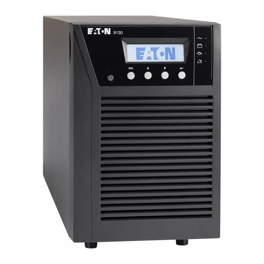
-
Contents
-
Table of Contents
-
Troubleshooting
-
Bookmarks
Quick Links
Powerware Series
®
Eaton 9130 UPS
700–3000 VA
User’s Guide
Related Manuals for Eaton 9130 UPS
Summary of Contents for Eaton 9130 UPS
-
Page 1
Powerware Series ® Eaton 9130 UPS 700–3000 VA User’s Guide… -
Page 2
Fire Protection Association, Inc. Phillips is a registered trademark of Phillips Screw Company. All other trademarks are property of their respective companies. ECopyright 2008–2010 Eaton Corporation, Raleigh, NC, USA. All rights reserved. No part of this document may be reproduced in any way without the express written approval of Eaton Corporation. -
Page 3
Class B EMC Statements (Low Voltage Models up to 1500 VA and High Voltage Models up to 3000 VA) FCC Part 15 This equipment has been tested and found to comply with the limits for a Class B digital device, pursuant to NOTE part 15 of the FCC Rules. -
Page 4: Special Symbols
92/31/EEC, Amending Directive 89/336/EEC relating to EMC The EC Declaration of Conformity is available upon request for products with a CE mark. For copies of the EC Declaration of Conformity, contact: Eaton Power Quality Oy Koskelontie 13 FIN-02920 Espoo Finland…
-
Page 5: Table Of Contents
…………164201718 Rev 3 www.eaton.com/powerquality Eaton ® 9130 UPS (700–3000 VA) User’s Guide…
-
Page 6
…………..164201718 Rev 3 www.eaton.com/powerquality Eaton ® 9130 UPS (700–3000 VA) User’s Guide… -
Page 7
……….164201718 Rev 3 www.eaton.com/powerquality Eaton ® 9130 UPS (700–3000 VA) User’s Guide… -
Page 8
TABLE OF CONTENTS 164201718 Rev 3 www.eaton.com/powerquality Eaton ® 9130 UPS (700–3000 VA) User’s Guide… -
Page 9: Introduction
— causing hours of lost productivity and expensive repairs. With the Eaton 9130, you can safely eliminate the effects of power disturbances and guard the integrity of your equipment. Providing…
-
Page 10
INTRODUCTION Figure 1 shows the Eaton 9130 rackmount UPS, and Figure 2 shows the optional rackmount EBM. Figure 1. The Eaton 9130 Rackmount UPS Figure 2. The Eaton 9130 Rackmount EBM Figure 3 shows the Eaton 9130 tower UPS and optional EBM. -
Page 11: Safety Warnings
UPS internal battery connector (see Figure 24 on page 64 for rackmount models or Figure 26 on page 67 for tower models). 164201718 Rev 3 www.eaton.com/powerquality Eaton ® 9130 UPS (700–3000 VA) User’s Guide…
-
Page 12
I overensstemmelse med internationale normer og bestemmelser for el-installation må det udstyr, der er forbundet til udgangen af denne UPS, tilsammen ikke overskride en jordafdelingsspænding på mere end 3,5 milliampere. 164201718 Rev 3 www.eaton.com/powerquality Eaton ® 9130 UPS (700–3000 VA) User’s Guide… -
Page 13: Belangrijke Veiligheidsinstructies
Sluit om brandgevaar te voorkomen de apparatuur uitsluitend aan op een circuit voorzien van een overstroombeveiliging voor vertakte circuits van maximaal 100 A in overeenstemming met de NEC (Nationale Elektriciteitsvoorschriften), ANSI/NFPA 70. 164201718 Rev 3 www.eaton.com/powerquality Eaton ® 9130 UPS (700–3000 VA) User’s Guide…
-
Page 14
Ympäristön lämpötila ei saa ylittää 40 °C. Älä käytä lähellä vettä ja vältä kosteita tiloja (95 % maksimi). 164201718 Rev 3 www.eaton.com/powerquality Eaton ® 9130 UPS (700–3000 VA) User’s Guide… -
Page 15
La température ambiante ne doit pas dépasser 40 °C. Ne pas utiliser à proximité d’eau ou dans une atmosphère excessivement humide (95 % maximum). 164201718 Rev 3 www.eaton.com/powerquality Eaton ® 9130 UPS (700–3000 VA) User’s Guide… -
Page 16: Wichtige Sicherheitsanweisungen
W A R N U N G Die USV führt lebensgefährliche Spannungen. Alle Reparatur- und Wartungsarbeiten sollten nur von Kundendienstfachleuten durchgeführt werden. Die USV enthält keine vom Benutzer zu wartenden Komponenten. 164201718 Rev 3 www.eaton.com/powerquality Eaton ® 9130 UPS (700–3000 VA) User’s Guide…
-
Page 17: Avvisi Di Sicurezza
Il presente manuale contiene importanti istruzioni da seguire durante l’installazione e la manutenzione dell’UPS e delle batterie. Leggere integralmente le istruzioni prima di utilizzare l’apparecchiatura e conservare il presente manuale per futuro riferimento. 164201718 Rev 3 www.eaton.com/powerquality Eaton ® 9130 UPS (700–3000 VA) User’s Guide…
-
Page 18
Le batterie devono essere smaltite in modo corretto. Per i requisiti di smaltimento fare riferimento alle disposizioni locali. Non gettare mai le batterie nel fuoco poichè potrebbero esplodere se esposte alle fiamme. 164201718 Rev 3 www.eaton.com/powerquality Eaton ® 9130 UPS (700–3000 VA) User’s Guide… -
Page 19: Viktig Sikkerhetsinformasion
Batterier må fjernes på korrekt måte. Se lokale forskrifter vedrørende krav om fjerning av batterier. Kast aldri batterier i flammer, da de kan eksplodere, hvis de utsettes for åpen ild. 164201718 Rev 3 www.eaton.com/powerquality Eaton ® 9130 UPS (700–3000 VA) User’s Guide…
-
Page 20
Siga as instruções apropriadas ao desfazer‐se das baterias. Consulte os códigos do local para maiores informações sobre os regulamentos de descarte de produtos. Nunca jogue as baterias no fogo, porque há risco de explosão. 164201718 Rev 3 www.eaton.com/powerquality Eaton ® 9130 UPS (700–3000 VA) User’s Guide… -
Page 21
Äëÿ îáåñïå÷åíèÿ ñîáëþäåíèÿ òðåáîâàíèé ìåæäóíàðîäíûõ ñòàíäàðòîâ è òðåáîâàíèé ê ðàçâîäêå ýëåêòðè÷åñêèõ öåïåé, ñóììàðíàÿ âåëè÷èíà òîêà óòå÷êè íà çåìëþ âñåãî îáîðóäîâàíèÿ, ïîäêëþ÷åííîãî ê âûõîäó ÈÁÏ, íå äîëæíà ïðåâûøàòü 3,5 ìèëëèàìïåðà. 164201718 Rev 3 www.eaton.com/powerquality Eaton ® 9130 UPS (700–3000 VA) User’s Guide… -
Page 22: Advertencias De Seguridad
Para reducir el riesgo de incendio, realice la conexión únicamente hacia un circuito que cuente con un máximo de 100 amperios de protección contra sobrecorriente de circuito derivado, de acuerdo con el Código Eléctrico Nacional, ANSI/NFPA 70. 164201718 Rev 3 www.eaton.com/powerquality Eaton ® 9130 UPS (700–3000 VA) User’s Guide…
-
Page 23
är kontrollerade och där inga ledande föroreningar förekommer. Omgivande temperatur får ej överstiga 40°C. Använd inte utrustningen nära vatten eller vid hög luftfuktighet (max 95 %). 164201718 Rev 3 www.eaton.com/powerquality Eaton ® 9130 UPS (700–3000 VA) User’s Guide… -
Page 24
Håll ej behörig personal borta från batterierna. Batterierna måste avyttras enligt anvisningarna i lokal lagstiftning. Använda batterier får aldrig brännas upp. De kan explodera. 164201718 Rev 3 www.eaton.com/powerquality Eaton ® 9130 UPS (700–3000 VA) User’s Guide… -
Page 25: Installation
NOTE Check the battery recharge date on the shipping carton label. If the date has passed and the batteries were never recharged, do not use the UPS. Contact your service representative. 164201718 Rev 3 www.eaton.com/powerquality Eaton ® 9130 UPS (700–3000 VA) User’s Guide…
-
Page 26: Unpacking The Cabinet
NOTE Discard the EBM user’s guide if you are installing the EBM with a new UPS at the same time. Use the UPS user’s guide to install both the UPS and the EBM. 164201718 Rev 3 www.eaton.com/powerquality Eaton ® 9130 UPS (700–3000 VA) User’s Guide…
-
Page 27: Rackmount Installation
INSTALLATION Rackmount Installation The Eaton 9130 rackmount cabinet comes with all of the hardware required for installation in a standard EIA or JIS seismic rackmount configuration with square and round mounting holes. The rail assemblies adjust to mount in 48-cm (19-inch) racks with front to rear rail distances from 61 to 76 cm (24 to 30 inches) deep.
-
Page 28: Rackmount Setup
Figure 4. Do not tighten the screws. Adjust each rail size for the depth of your rack. Rear Rails 8 Pan-Head Screws (6 places) Left Rail Right Rail Figure 4. Assembling the Rails 164201718 Rev 3 www.eaton.com/powerquality Eaton ® 9130 UPS (700–3000 VA) User’s Guide…
-
Page 29
Align the mounting brackets with the screw holes on each side of the UPS and secure with the supplied M4 8 flat-head screws (see Figure 6). 164201718 Rev 3 www.eaton.com/powerquality Eaton ® 9130 UPS (700–3000 VA) User’s Guide… -
Page 30
Repeat for any optional cabinets. M6 Cage Nuts (4 places) 16 Pan-Head Screws (4 places) Figure 7. Securing the Front of the Cabinet 164201718 Rev 3 www.eaton.com/powerquality Eaton ® 9130 UPS (700–3000 VA) User’s Guide… -
Page 31: Rackmount Wiring Installation
To remove the cover, remove and retain the two screws on the right side of the cover. Grasp the top and bottom of the cover and slide the cover to the right. 164201718 Rev 3 www.eaton.com/powerquality Eaton ® 9130 UPS (700–3000 VA) User’s Guide…
-
Page 32
Clip the wires of the rightmost connector to the battery panel in its new position. 2000–3000 VA models. Connect red to red, and black to black. Press the two parts tightly together to ensure a proper connection. 164201718 Rev 3 www.eaton.com/powerquality Eaton ® 9130 UPS (700–3000 VA) User’s Guide… -
Page 33
If an emergency power-off (disconnect) switch is required by local codes, see “Remote Emergency Power-off” (REPO) on page 56 to install the REPO switch before powering on the UPS. Continue to “UPS Initial Startup” on page 34. 164201718 Rev 3 www.eaton.com/powerquality Eaton ® 9130 UPS (700–3000 VA) User’s Guide… -
Page 34: Connecting The Ebm(S)
To remove the cover, remove and retain the two screws on the right side of the cover. Grasp the sides of the cover and slide the cover to the left and then away from the cabinet. 164201718 Rev 3 www.eaton.com/powerquality Eaton ® 9130 UPS (700–3000 VA) User’s Guide…
-
Page 35
If you are installing more than one EBM, for each additional EBM remove the EBM cable knockout on the top and bottom of the EBM front cover. See Figure 12 for the location of the EBM cable knockouts. 164201718 Rev 3 www.eaton.com/powerquality Eaton ® 9130 UPS (700–3000 VA) User’s Guide… -
Page 36
Verify that the EBM connections are tight and that adequate bend radius and strain relief exist for each cable. Up to 1500 VA Models 2000–3000 VA Models Figure 13. Typical EBM Installation 164201718 Rev 3 www.eaton.com/powerquality Eaton ® 9130 UPS (700–3000 VA) User’s Guide… -
Page 37: Tower Installation
Return to Step 4 on page 25 to continue the UPS installation. Tower Installation The Eaton 9130 tower cabinet comes fully assembled and ready to connect. C A U T I O N The cabinet is heavy (see page 78).
-
Page 38: Tower Wiring Installation
NOTE A ribbon cable connects the LCD control panel to the UPS. Do not pull on the cable or disconnect it. NOTE Leave ribbon cable connected. Figure 14. Removing the UPS Front Cover 164201718 Rev 3 www.eaton.com/powerquality Eaton ® 9130 UPS (700–3000 VA) User’s Guide…
-
Page 39
To replace the cover, verify that the ribbon cable is protected, then insert the clips on the back of the cover into the cabinet and push firmly to snap the cover into place. 164201718 Rev 3 www.eaton.com/powerquality Eaton ® 9130 UPS (700–3000 VA) User’s Guide… -
Page 40: Connecting The Ebm(S)
EBM cable connection using the retained screws. Verify that the EBM connections are tight and that adequate bend radius and strain relief exist for each cable. Continue to “UPS Initial Startup” on page 34. 164201718 Rev 3 www.eaton.com/powerquality Eaton ® 9130 UPS (700–3000 VA) User’s Guide…
-
Page 41
INSTALLATION Remove cable retention clip. Plug in EBM cable. Rotate clip. Reinstall cable retention clip. 1000–1500 VA Models 2000–3000 VA Models Figure 16. Connecting the EBMs 164201718 Rev 3 www.eaton.com/powerquality Eaton ® 9130 UPS (700–3000 VA) User’s Guide… -
Page 42: Ups Initial Startup
Check the UPS status from the front panel to view the active alarms. Correct the alarms and restart if necessary. 164201718 Rev 3 www.eaton.com/powerquality Eaton ® 9130 UPS (700–3000 VA) User’s Guide…
-
Page 43
UPS display. Deactivate the external REPO switch and restart the UPS. NOTE The internal batteries charge to 90% capacity in less than 3 hours. However, Eaton recommends that the batteries charge for 48 hours after installation or long-term storage. If optional EBMs are installed, see the recharge times listed in Table 25 on page 90. -
Page 44
INSTALLATION 164201718 Rev 3 www.eaton.com/powerquality Eaton ® 9130 UPS (700–3000 VA) User’s Guide… -
Page 45: Operation
Chapter 4 Operation This chapter contains information on how to use the Eaton 9130, including front panel operation, operating modes, UPS startup and shutdown, transferring the UPS between modes, retrieving the Event Log, setting the power strategy, and configuring bypass settings, load segments, and battery settings.
-
Page 46: Changing The Language
( and ) to scroll through the menu structure. Press the Enter ) button to select an option. Press the button to cancel or return to the previous menu. 164201718 Rev 3 www.eaton.com/powerquality Eaton ® 9130 UPS (700–3000 VA) User’s Guide…
-
Page 47
Returns all settings to original values Settings Identification UPS Type / Part Number / Serial Number / Firmware Settings User Settings See Table 3 for details. Service Settings This menu is password-protected. 164201718 Rev 3 www.eaton.com/powerquality Eaton ® 9130 UPS (700–3000 VA) User’s Guide… -
Page 48: User Settings
120V (low voltage models) [200V] [208V] [220V] [230V] [240V] 230V (high voltage models) [Autosensing] Output Frequency [50Hz] [60Hz] [Autosensing] Autosensing * See “Configuring Bypass Settings” on page 48. 164201718 Rev 3 www.eaton.com/powerquality Eaton ® 9130 UPS (700–3000 VA) User’s Guide…
-
Page 49
UPSs with separate supply sources for the rectifier and bypass inputs. On Battery Notice Delay [0] [1s] [2s]…[99s] * See “Configuring Bypass Settings” on page 48. 164201718 Rev 3 www.eaton.com/powerquality Eaton ® 9130 UPS (700–3000 VA) User’s Guide… -
Page 50
Automatic Battery Support Tests [Enabled] [Disabled] Enabled See “Running Automatic Battery Tests” on page 52. Ambient Temperature Warning [Enabled] [Disabled] Enabled * See “Configuring Bypass Settings” on page 48. 164201718 Rev 3 www.eaton.com/powerquality Eaton ® 9130 UPS (700–3000 VA) User’s Guide… -
Page 51: Operating Modes
Open Input Polarity * See “Configuring Bypass Settings” on page 48. Operating Modes The Eaton 9130 front panel indicates the UPS status through the UPS indicators (see Figure 17 on page 37). Normal Mode During Normal mode, the indicator illuminates solid and the UPS is powered from the utility.
-
Page 52: Bypass Mode
The UPS has an overload condition listed in Table 19 on page 84. NOTE The UPS shuts down after a specified delay for overload conditions listed in Table 19 on page 84. The UPS remains on to alarm the fault. 164201718 Rev 3 www.eaton.com/powerquality Eaton ® 9130 UPS (700–3000 VA) User’s Guide…
-
Page 53: Standby Mode
Verify that the UPS transfers to Standby mode (”UPS on standby”). Press the button on the UPS front panel for at least one second. The UPS front panel display changes status to “UPS starting…”. 164201718 Rev 3 www.eaton.com/powerquality Eaton ® 9130 UPS (700–3000 VA) User’s Guide…
-
Page 54: Starting The Ups On Battery
Check the UPS status from the front panel to view the active alarms. Correct the alarms and restart if necessary. Press the button until the start screen appears. 164201718 Rev 3 www.eaton.com/powerquality Eaton ® 9130 UPS (700–3000 VA) User’s Guide…
-
Page 55: Ups Shutdown
Use the connected communication device to view or print the information. The report is delivered in ASCII format. 164201718 Rev 3 www.eaton.com/powerquality Eaton ® 9130 UPS (700–3000 VA) User’s Guide…
-
Page 56: Setting Power Strategy
Bypass voltage is between the “Bypass Voltage Low Limit” and “Bypass Voltage High Limit” settings. Bypass frequency is within nominal frequency ±5 Hz. The inverter is synchronized with Bypass when the “Unsynchronized Transfers” setting is disabled. 164201718 Rev 3 www.eaton.com/powerquality Eaton ® 9130 UPS (700–3000 VA) User’s Guide…
-
Page 57: Configuring Load Segments
Press any button to activate the menu options, then select CONTROL and LOAD SEGMENTS. Set the desired load segment ON or OFF, and ENTER to confirm. Set the other load segment if applicable. 164201718 Rev 3 www.eaton.com/powerquality Eaton ® 9130 UPS (700–3000 VA) User’s Guide…
-
Page 58
Set the shutdown delay for one load segment, and ENTER to confirm. Set the other load segment if applicable. NOTE Load segment On/Off commands issued through the Control menu overrule the user settings for load segments. 164201718 Rev 3 www.eaton.com/powerquality Eaton ® 9130 UPS (700–3000 VA) User’s Guide… -
Page 59: Configuring Battery Settings
NOTE The UPS contains one battery string; each EBM contains two battery strings. Press the button to save the setting. Press the button until the start screen appears. 164201718 Rev 3 www.eaton.com/powerquality Eaton ® 9130 UPS (700–3000 VA) User’s Guide…
-
Page 60: Running Automatic Battery Tests
“Automatic Start Delay” setting. You can also configure UPS restart to depend on the battery charge level, using the “Battery Charge % to Restart” setting. 164201718 Rev 3 www.eaton.com/powerquality Eaton ® 9130 UPS (700–3000 VA) User’s Guide…
-
Page 61: Communication
See “Rear Panels” on page 91 for rear panel diagrams for each model. Communication Bay REPO Output Input RS-232 Standard Relay Output Contact Figure 18. Communication Options and Control Terminals (PW9130L1000R-XL2U Model Shown) 164201718 Rev 3 www.eaton.com/powerquality Eaton ® 9130 UPS (700–3000 VA) User’s Guide…
-
Page 62: Installing Communication Options And Control Terminals
Route and tie the cable(s) out of the way. Continue to “Operation” on page 37 to start up the UPS. Communication Options The Eaton 9130 has serial communication capabilities through the USB and RS-232 communication ports or through a connectivity card in the available communication bay.
-
Page 63
When the selected condition is active, output signals on Pins 1 and 8 shift from Low (positive voltage) to High (negative voltage). When the condition no longer exists, the output signal returns to Low. 164201718 Rev 3 www.eaton.com/powerquality Eaton ® 9130 UPS (700–3000 VA) User’s Guide… -
Page 64: Connectivity Cards
COMMUNICATION Connectivity Cards Connectivity cards allow the UPS to communicate in a variety of networking environments and with different types of devices. The Eaton 9130 has one available communication bay for the following connectivity cards: ConnectUPS -BD Web/SNMP Card — has SNMP and HTTP capabilities as well as monitoring through a Web browser interface;…
-
Page 65
Bypass” state, the UPS transfers to Bypass model in every condition except frequency converter and generator mode. NOTE Always test the REPO function before applying your critical load to avoid accidental load loss. 164201718 Rev 3 www.eaton.com/powerquality Eaton ® 9130 UPS (700–3000 VA) User’s Guide… -
Page 66: Relay Output Contacts
Controls an optional external battery charger on and off Figure 22 shows a schematic of the relay output contacts. Normally Open Normally Closed Relay Output Common Figure 22. Standard Relay Port Connections 164201718 Rev 3 www.eaton.com/powerquality Eaton ® 9130 UPS (700–3000 VA) User’s Guide…
-
Page 67: Programmable Signal Inputs
If active, the UPS generates the “Building Alarm 1” alarm. Table 7. Polarity Options Input Description High Active state on high voltage (+Udc) level Active state on low voltage (GND or -Udc) level 164201718 Rev 3 www.eaton.com/powerquality Eaton ® 9130 UPS (700–3000 VA) User’s Guide…
-
Page 68: Modem Operation
It also gives you a complete record of critical power events, and it notifies you of important UPS or power information. If there is a power outage and the Eaton 9130 UPS battery power becomes low, LanSafe software can automatically shut down your computer system to protect your data before the UPS shutdown occurs.
-
Page 69: Ups Maintenance
Batteries used beyond expected service life will often have severely reduced runtimes. Replace batteries at least every 5 years to keep units running at peak efficiency. 164201718 Rev 3 www.eaton.com/powerquality Eaton ® 9130 UPS (700–3000 VA) User’s Guide…
-
Page 70: Storing The Ups And Batteries
If you store the UPS for a long period, recharge the battery every 6 months by connecting the UPS to utility power. The internal batteries charge to 90% capacity in less than 3 hours. However, Eaton recommends that the batteries charge for 48 hours after long-term storage.
-
Page 71: Replacing Rackmount Ups Internal Batteries
Grasp the top and bottom of the cover and slide the cover to the right. NOTE A ribbon cable connects the LCD control panel to the UPS. Do not pull on the cable or disconnect it. 164201718 Rev 3 www.eaton.com/powerquality Eaton ® 9130 UPS (700–3000 VA) User’s Guide…
-
Page 72
Grasp an edge of the battery cover plate and pull it forward gently. Remove and retain the battery cover plate. See Figure 24 for the location of the battery cover plate. 164201718 Rev 3 www.eaton.com/powerquality Eaton ® 9130 UPS (700–3000 VA) User’s Guide… -
Page 73
Slide the cover to the left until it aligns with the left front cover. Reinstall the two screws on the right side of the right front cover. 11. Continue to “Testing New Batteries” on page 72. 164201718 Rev 3 www.eaton.com/powerquality Eaton ® 9130 UPS (700–3000 VA) User’s Guide… -
Page 74: Replacing Tower Ups Internal Batteries
NOTE A ribbon cable connects the LCD control panel to the UPS. Do not pull on the cable or disconnect it. NOTE Leave ribbon cable connected. Figure 25. Removing the UPS Front Cover 164201718 Rev 3 www.eaton.com/powerquality Eaton ® 9130 UPS (700–3000 VA) User’s Guide…
-
Page 75
NOTE Verify that the replacement batteries have the same rating as the batteries being replaced. Slide the new battery package into the cabinet. Push the battery package in firmly. 164201718 Rev 3 www.eaton.com/powerquality Eaton ® 9130 UPS (700–3000 VA) User’s Guide… -
Page 76
10. Continue to “Testing New Batteries” on page 72. 164201718 Rev 3 www.eaton.com/powerquality Eaton ® 9130 UPS (700–3000 VA) User’s Guide… -
Page 77: Replacing Rackmount Ebms
Top EBM Cable Knockout EBM Cover Hook Bottom EBM Cable Knockout (underneath cover) Figure 27. Removing the EBM Front Cover 164201718 Rev 3 www.eaton.com/powerquality Eaton ® 9130 UPS (700–3000 VA) User’s Guide…
-
Page 78
EBM. Repeat for any additional EBMs. Verify that the EBM connections are tight and that adequate bend radius and strain relief exist for each cable. 164201718 Rev 3 www.eaton.com/powerquality Eaton ® 9130 UPS (700–3000 VA) User’s Guide… -
Page 79: Replacing Tower Ebms
Insert the EBM cable into the UPS battery connector quickly and firmly. Plug the EBM cable(s) into the battery connector(s) as shown in Figure 16 on page 33. Up to four EBMs may be connected to the UPS. 164201718 Rev 3 www.eaton.com/powerquality Eaton ® 9130 UPS (700–3000 VA) User’s Guide…
-
Page 80: Testing New Batteries
During the battery test, the UPS transfers to Battery mode and discharges the batteries for 25 seconds. The front panel displays “Battery test running” and the percentage of the test completed. 164201718 Rev 3 www.eaton.com/powerquality Eaton ® 9130 UPS (700–3000 VA) User’s Guide…
-
Page 81: Recycling The Used Battery Or Ups
To keep the UPS firmware updated with the latest improvements and benefits, visit often for updates. You www.eaton.com/powerquality can download the latest firmware version and the instructions for installing it. 164201718 Rev 3 www.eaton.com/powerquality Eaton ® 9130 UPS (700–3000 VA) User’s Guide…
-
Page 82
UPS MAINTENANCE 164201718 Rev 3 www.eaton.com/powerquality Eaton ® 9130 UPS (700–3000 VA) User’s Guide… -
Page 83: Specifications
700–1000 VA PW9130N1500R-EBM2U 48 Vdc 1500 VA Rackmount PW9130N3000R-EBM2U 72 Vdc 2000–3000 VA PW9130N1000T-EBM 36 Vdc 1000 VA PW9130N1500T-EBM 48 Vdc 1500 VA Tower PW9130N3000T-EBM 96 Vdc 2000–3000 VA 164201718 Rev 3 www.eaton.com/powerquality Eaton ® 9130 UPS (700–3000 VA) User’s Guide…
-
Page 84
1500 VA / 1350W Figure 32 on page 92 PW9130G2000R-XL2UAU 2000 VA / 1800W Figure 38 on page 93 PW9130G3000R-XL2UAU 3000 VA / 2700W Figure 42 on page 94 164201718 Rev 3 www.eaton.com/powerquality Eaton ® 9130 UPS (700–3000 VA) User’s Guide… -
Page 85
1500 VA / 1350W Figure 58 on page 98 PW9130G2000T-XLAU 2000 VA / 1800W Figure 59 on page 99 PW9130G3000T-XLAU 3000 VA / 2700W Figure 60 on page 99 164201718 Rev 3 www.eaton.com/powerquality Eaton ® 9130 UPS (700–3000 VA) User’s Guide… -
Page 86
22.1 kg (48.7 lb) (3.4” 17.2” 16.9”) PW9130N1500R-EBM2U 86.5 430 mm 28.1 kg (62.0 lb) (3.4” 17.2” 16.9”) PW9130N3000R-EBM2U 86.5 600 mm 41.0 kg (90.6 lb) (3.4” 17.2” 23.6”) 164201718 Rev 3 www.eaton.com/powerquality Eaton ® 9130 UPS (700–3000 VA) User’s Guide… -
Page 87
Nominal Frequency 50/60 Hz auto-sensing Frequency Range 40–70 Hz before transfer to battery Bypass Voltage Range +10/-15% of nominal (default) Noise Filtering MOVs for normal and common mode noise 164201718 Rev 3 www.eaton.com/powerquality Eaton ® 9130 UPS (700–3000 VA) User’s Guide… -
Page 88
180–276 Vac PW9130G3000R-XL2UAU 240V / 13.0A 200*, 208**, 220, 230, 240 180–276 Vac * 100V and 200V are derated by 20%. ** 110V and 208V are derated by 10%. 164201718 Rev 3 www.eaton.com/powerquality Eaton ® 9130 UPS (700–3000 VA) User’s Guide… -
Page 89
180–276 Vac PW9130G3000T-XLAU 240V / 12.5A 200*, 208**, 220, 230, 240 180–276 Vac * 100V and 200V are derated by 20%. ** 110V and 208V are derated by 10%. 164201718 Rev 3 www.eaton.com/powerquality Eaton ® 9130 UPS (700–3000 VA) User’s Guide… -
Page 90
Aust. 10A to IEC 320-10A PW9130G1500R-XL2UAU IEC C14-10A Aust. 10A to IEC 320-10A PW9130G2000R-XL2UAU IEC C14-10A Aust. 10A to IEC 320-10A PW9130G3000R-XL2UAU IEC C20-16A Aust. 15A to IEC 320-16A 164201718 Rev 3 www.eaton.com/powerquality Eaton ® 9130 UPS (700–3000 VA) User’s Guide… -
Page 91
Aust. 10A to IEC 320-10A PW9130G1500T-XLAU IEC C14-10A Aust. 10A to IEC 320-10A PW9130G2000T-XLAU IEC C14-10A Aust. 10A to IEC 320-10A PW9130G3000T-XLAU IEC C20-16A Aust. 15A to IEC 320-16A 164201718 Rev 3 www.eaton.com/powerquality Eaton ® 9130 UPS (700–3000 VA) User’s Guide… -
Page 92
<3% THD on linear load; <5% THD on non-linear load Transfer Time Online mode: 0 ms (no break) High Efficiency mode: 5 ms maximum (due to loss of utility) Power Factor Load Crest Factor 3 to 1 164201718 Rev 3 www.eaton.com/powerquality Eaton ® 9130 UPS (700–3000 VA) User’s Guide… -
Page 93
(4) C13, (2) Aust 10A (2) IEC-IEC 10A PW9130G2000R-XL2UAU (4) C13, (4) Aust 10A (2) IEC-IEC 10A PW9130G3000R-XL2UAU (4) C13, (1) C19, (3) Aust 10A (2) IEC-IEC 10A, (1) IEC-IEC 15A 164201718 Rev 3 www.eaton.com/powerquality Eaton ® 9130 UPS (700–3000 VA) User’s Guide… -
Page 94
(4) Aust 10A None PW9130G1000T-XLAU (4) Aust 10A None PW9130G1500T-XLAU (4) Aust 10A None PW9130G2000T-XLAU (1) C13, (5) Aust 10A None PW9130G3000T-XLAU (1) C19, (5) Aust 15A None 164201718 Rev 3 www.eaton.com/powerquality Eaton ® 9130 UPS (700–3000 VA) User’s Guide… -
Page 95
Up to 3,000 meters (9,843 ft) above sea level Transit Altitude Up to 10,000 meters (32,808 ft) above sea level Audible Noise <50 dBA at 1 meter typical Leakage Current <1.5 mA 164201718 Rev 3 www.eaton.com/powerquality Eaton ® 9130 UPS (700–3000 VA) User’s Guide… -
Page 96
PW9130L2000R-XL2U PW9130G2000R-XL2U PW9130i2000R-XL2U PW9130G2000R-XL2UEU PW9130G2000R-XL2UAU PW9130L2500R-XL2U PW9130G2500R-XL2U PW9130G2500R-XL2UEU PW9130L3000R-XL2U PW9130G3000R-XL2U PW9130i3000R-XL2U PW9130G3000R-XL2UEU PW9130G3000R-XL2UAU NOTE Battery times are approximate and vary depending on the load configuration and battery charge. 164201718 Rev 3 www.eaton.com/powerquality Eaton ® 9130 UPS (700–3000 VA) User’s Guide… -
Page 97
PW9130L1500T-XL PW9130i1500T-XL PW9130G1500T-XLAU PW9130L2000T-XL PW9130G2000T-XL PW9130i2000T-XL PW9130G2000T-XLEU PW9130G2000T-XLAU PW9130L3000T-XL PW9130G3000T-XL PW9130i3000T-XL PW9130G3000T-XLEU PW9130G3000T-XLAU NOTE Battery times are approximate and vary depending on the load configuration and battery charge. 164201718 Rev 3 www.eaton.com/powerquality Eaton ® 9130 UPS (700–3000 VA) User’s Guide… -
Page 98
1 EBM: 9 hours; 2 EBMs: 15 hours; 3 EBMs: 21 hours; 4 EBMs: 27 hours Battery Port External three-pole Anderson connector on UPS for connection to EBM 164201718 Rev 3 www.eaton.com/powerquality Eaton ® 9130 UPS (700–3000 VA) User’s Guide… -
Page 99: Rear Panels
Table 15 through Table 21 (pages 80 through 86). For a description of communication features, see Figure 18 on page 53. Figure 28. Models PW9130L700R-XL2U, PW9130L1000R-XL2U Figure 29. Model PW9130G1000R-XL2U Figure 30. Models PW9130i1000R-XL2U, PW9130G1000R-XL2UEU 164201718 Rev 3 www.eaton.com/powerquality Eaton ® 9130 UPS (700–3000 VA) User’s Guide…
-
Page 100
SPECIFICATIONS Figure 31. Model PW9130G1000R-XL2UAU Figure 32. Model PW9130G1500R-XL2UAU Figure 33. Model PW9130L1500R-XL2U Figure 34. Model PW9130i1500R-XL2U 164201718 Rev 3 www.eaton.com/powerquality Eaton ® 9130 UPS (700–3000 VA) User’s Guide… -
Page 101
SPECIFICATIONS Figure 35. Model PW9130L2000R-XL2U Figure 36. Model PW9130G2000R-XL2U Figure 37. Models PW9130i2000R-XL2U, PW9130G2000R-XL2UEU Figure 38. Model PW9130G2000R-XL2UAU 164201718 Rev 3 www.eaton.com/powerquality Eaton ® 9130 UPS (700–3000 VA) User’s Guide… -
Page 102
SPECIFICATIONS Figure 39. Models PW9130L2500R-XL2U, PW9130L3000R-XL2U Figure 40. Models PW9130G2500R-XL2U, PW9130G3000R-XL2U Figure 41. Models PW9130G2500R-XL2UEU, PW9130i3000R-XL2U, PW9130G3000R-XL2UEU Figure 42. Model PW9130G3000R-XL2UAU 164201718 Rev 3 www.eaton.com/powerquality Eaton ® 9130 UPS (700–3000 VA) User’s Guide… -
Page 103
SPECIFICATIONS Figure 43. Model PW9130L700T-XL Figure 44. Model PW9130L1000T-XL Figure 45. Model PW9130L1500T-XL Figure 46. Model PW9130L2000T-XL 164201718 Rev 3 www.eaton.com/powerquality Eaton ® 9130 UPS (700–3000 VA) User’s Guide… -
Page 104
SPECIFICATIONS Figure 47. Model PW9130L3000T-XL Figure 48. Model PW9130G1000T-XL Figure 49. Model PW9130G2000T-XL Figure 50. Model PW9130G3000T-XL 164201718 Rev 3 www.eaton.com/powerquality Eaton ® 9130 UPS (700–3000 VA) User’s Guide… -
Page 105
SPECIFICATIONS Figure 51. Model PW9130i700T-XL Figure 52. Model PW9130G1000T-XLEU and PW9130i1000T-XL Figure 53. Model PW9130i1500T-XL Figure 54. Models PW9130G2000T-XLEU and PW9130i2000T-XL 164201718 Rev 3 www.eaton.com/powerquality Eaton ® 9130 UPS (700–3000 VA) User’s Guide… -
Page 106
SPECIFICATIONS Figure 55. Models PW9130G3000T-XLEU and Figure 56. Model PW9130G700T-XLAU PW9130i3000T-XL Figure 57. Model PW9130G1000T-XLAU Figure 58. Model PW9130G1500T-XLAU 164201718 Rev 3 www.eaton.com/powerquality Eaton ® 9130 UPS (700–3000 VA) User’s Guide… -
Page 107
SPECIFICATIONS Figure 59. Model PW9130G2000T-XLAU Figure 60. Model PW9130G3000T-XLAU 164201718 Rev 3 www.eaton.com/powerquality Eaton ® 9130 UPS (700–3000 VA) User’s Guide… -
Page 108
SPECIFICATIONS 164201718 Rev 3 www.eaton.com/powerquality Eaton ® 9130 UPS (700–3000 VA) User’s Guide… -
Page 109: Troubleshooting
Chapter 8 Troubleshooting The Eaton 9130 is designed for durable, automatic operation and also alerts you whenever potential operating problems may occur. Usually the alarms shown by the control panel do not mean that the output power is affected. Instead, they are preventive alarms intended to alert the user.
-
Page 110
The batteries are disconnected. Verify that all batteries are properly connected. If LED is on. the condition persists, contact your service representative. 1 beep every second. 164201718 Rev 3 www.eaton.com/powerquality Eaton ® 9130 UPS (700–3000 VA) User’s Guide… -
Page 111
The UPS is in Standby mode. Supply power to the connected equipment: Press UPS output receptacles. the On/Off button for at least 1 second, until the front panel displays “UPS starting…”. 164201718 Rev 3 www.eaton.com/powerquality Eaton ® 9130 UPS (700–3000 VA) User’s Guide… -
Page 112
Check that the “Serial Port Configuration” setting is work. speed is set incorrectly for USB. set to 9600 bps. See “User Settings” on page 40. USB requires 9600 bps. 164201718 Rev 3 www.eaton.com/powerquality Eaton ® 9130 UPS (700–3000 VA) User’s Guide… -
Page 113: Silencing The Alarm
A replacement or repair unit will be shipped, freight prepaid for all warrantied units. Help NOTE For critical applications, immediate replacement may be available. Call the Desk for the dealer or distributor nearest you. 164201718 Rev 3 www.eaton.com/powerquality Eaton ® 9130 UPS (700–3000 VA) User’s Guide…
-
Page 114
TROUBLESHOOTING 164201718 Rev 3 www.eaton.com/powerquality Eaton ® 9130 UPS (700–3000 VA) User’s Guide… -
Page 115
This limited warranty (this “Warranty”) applies only to the original End-User (the “End-User”) of any Eaton 9120, 9125, 9130, 9135, 9140, and FERRUPS up to 3.1 kVA Products (individually and collectively, the “Product”) purchased on or after June 1, 2004, and cannot be transferred. This Warranty applies even in the event that the Product is initially sold by Company for resale to an End-User. -
Page 116
Product is sold, Company shall have no obligation under this Warranty. Also during such time, the period of this Warranty shall continue to run and the expiration of this Warranty shall not be extended upon payment of any overdue or unpaid amounts. 164201718 Rev 3 www.eaton.com/powerquality Eaton ® 9130 UPS (700–3000 VA) User’s Guide… -
Page 117
In the USA, call the Customer Reliability Center 7×24 at 800-356-5737. Outside of the USA, call your local Eaton product sales or service representative. For comments or questions about this Warranty, write to the Customer Quality Representative, 3301 Spring Forest Road, Raleigh, North Carolina 27616 USA. -
Page 118
In the USA, call the Customer Reliability Center 7×24 at 800-356-5737. Outside of the USA, contact your local Eaton product sales or service representative. For comments or questions about this Load Protection Guaranty, write to the Customer Quality Representative, 3301 Spring Forest Road, Raleigh, North Carolina 27616 USA.
| 1 | Введение . . . . . . . . . . . . . . . . . . . . . . . . . . . . . . . . . . . . . . . . . . . . . . . . . . . . . . | 7 |
| 2 | Предупреждения по мерам безопасности. . . . . . . . . . . . . . . . . . . . . . . . . . . . . . . . | 9 |
| 3 | Установка . . . . . . . . . . . . . . . . . . . . . . . . . . . . . . . . . . . . . . . . . . . . . . . . . . . . . . | 11 |
| Осмотр оборудования . . . . . . . . . . . . . . . . . . . . . . . . . . . . . . . . . . . . . . . . . . . . . . | 11 | |
| Распаковка шкафа . . . . . . . . . . . . . . . . . . . . . . . . . . . . . . . . . . . . . . . . . . . . . . . . | 11 | |
| Проверка комплекта принадлежностей . . . . . . . . . . . . . . . . . . . . . . . . . . . . . . . . . . | 12 | |
| Установка в стойке . . . . . . . . . . . . . . . . . . . . . . . . . . . . . . . . . . . . . . . . . . . . . . . . | 12 | |
| Проверка принадлежностей комплекта направляющих . . . . . . . . . . . . . . . . . . . . . . . | 12 | |
| Необходимые инструменты . . . . . . . . . . . . . . . . . . . . . . . . . . . . . . . . . . . . . . . . . . . | 13 | |
| Вариант установки в стойке . . . . . . . . . . . . . . . . . . . . . . . . . . . . . . . . . . . . . . . . . . | 13 | |
| Монтаж проводки в стойке . . . . . . . . . . . . . . . . . . . . . . . . . . . . . . . . . . . . . . . . . . . | 16 | |
| Установка ИБП . . . . . . . . . . . . . . . . . . . . . . . . . . . . . . . . . . . . . . . . . . . . . . . . . . . | 16 | |
| Подключение EBM . . . . . . . . . . . . . . . . . . . . . . . . . . . . . . . . . . . . . . . . . . . . . . . . . | 18 | |
| Установка в виде башни . . . . . . . . . . . . . . . . . . . . . . . . . . . . . . . . . . . . . . . . . . . . . | 20 | |
| Проводка ИБП типа башня . . . . . . . . . . . . . . . . . . . . . . . . . . . . . . . . . . . . . . . . . . . . | 20 | |
| Установка ИБП . . . . . . . . . . . . . . . . . . . . . . . . . . . . . . . . . . . . . . . . . . . . . . . . . . . . | 20 | |
| Подключение EBM . . . . . . . . . . . . . . . . . . . . . . . . . . . . . . . . . . . . . . . . . . . . . . . . . . | 22 | |
| Первый запуск ИБП . . . . . . . . . . . . . . . . . . . . . . . . . . . . . . . . . . . . . . . . . . . . . . . . . | 23 | |
| 4 | Эксплуатация . . . . . . . . . . . . . . . . . . . . . . . . . . . . . . . . . . . . . . . . . . . . . . . . . . . . . | 26 |
| Функции панели управления . . . . . . . . . . . . . . . . . . . . . . . . . . . . . . . . . . . . . . . . . . | 26 | |
| Изменение языка . . . . . . . . . . . . . . . . . . . . . . . . . . . . . . . . . . . . . . . . . . . . . . . . . . | 27 | |
| Функции дисплея . . . . . . . . . . . . . . . . . . . . . . . . . . . . . . . . . . . . . . . . . . . . . . . . . . . | 27 | |
| Пользовательские настройки . . . . . . . . . . . . . . . . . . . . . . . . . . . . . . . . . . . . . . . . . . | 28 | |
| Рабочие режимы . . . . . . . . . . . . . . . . . . . . . . . . . . . . . . . . . . . . . . . . . . . . . . . . . . . | 30 | |
| Нормальный режим . . . . . . . . . . . . . . . . . . . . . . . . . . . . . . . . . . . . . . . . . . . . . . . . . . | 30 | |
| Режим работы от батарей . . . . . . . . . . . . . . . . . . . . . . . . . . . . . . . . . . . . . . . . . . . . . | 31 | |
| Режим байпаса . . . . . . . . . . . . . . . . . . . . . . . . . . . . . . . . . . . . . . . . . . . . . . . . . . . . . | 31 | |
| Режим ожидания . . . . . . . . . . . . . . . . . . . . . . . . . . . . . . . . . . . . . . . . . . . . . . . . . . . . | 31 | |
| Включение и выключение ИБП . . . . . . . . . . . . . . . . . . . . . . . . . . . . . . . . . . . . . . . . . | 32 | |
| Включение ИБП . . . . . . . . . . . . . . . . . . . . . . . . . . . . . . . . . . . . . . . . . . . . . . . . . . . . | 32 | |
| Запуск ИБП от батареи . . . . . . . . . . . . . . . . . . . . . . . . . . . . . . . . . . . . . . . . . . . . . . . | 33 | |
| Выключение ИБП . . . . . . . . . . . . . . . . . . . . . . . . . . . . . . . . . . . . . . . . . . . . . . . . . . . | 33 | |
| Переключение режимов ИБП . . . . . . . . . . . . . . . . . . . . . . . . . . . . . . . . . . . . . . . . . . . | 33 | |
| Просмотр журнала событий . . . . . . . . . . . . . . . . . . . . . . . . . . . . . . . . . . . . . . . . . . . . | 34 | |
| Настройка стратегии питания . . . . . . . . . . . . . . . . . . . . . . . . . . . . . . . . . . . . . . . . . . | 34 | |
| Настройка параметров байпаса . . . . . . . . . . . . . . . . . . . . . . . . . . . . . . . . . . . . . . . . . | 34 | |
| Настройка сегментов нагрузки . . . . . . . . . . . . . . . . . . . . . . . . . . . . . . . . . . . . . . . . . . | 35 | |
| Настройки батареи . . . . . . . . . . . . . . . . . . . . . . . . . . . . . . . . . . . . . . . . . . . . . . . . . . | 37 | |
| Конфигурирование ИБП для EBM . . . . . . . . . . . . . . . . . . . . . . . . . . . . . . . . . . . . . . . . | 37 | |
| Выполнение автоматических тестов батарей . . . . . . . . . . . . . . . . . . . . . . . . . . . . . . . . . . | 37 | |
| Конфигурирование автоматического перезапуска . . . . . . . . . . . . . . . . . . . . . . . . . . . . . . | 38 | |
| 5 | Коммуникация . . . . . . . . . . . . . . . . . . . . . . . . . . . . . . . . . . . . . . . . . . . . . . . . . . | 39 |
| Подключение коммуникационных устройств и клемм управления . . . . . . . . . . . . . . . . . . | 39 | |
| Коммуникационные опции . . . . . . . . . . . . . . . . . . . . . . . . . . . . . . . . . . . . . . . . . . . . . . | 40 | |
| Коммуникационные порты RS-232 и USB . . . . . . . . . . . . . . . . . . . . . . . . . . . . . . . . . . . | 40 | |
| Коммуникационные карты . . . . . . . . . . . . . . . . . . . . . . . . . . . . . . . . . . . . . . . . . . . . . . | 41 | |
| Дистанционное аварийное отключение . . . . . . . . . . . . . . . . . . . . . . . . . . . . . . . . . . . . . | 42 | |
| Релейные выходные контакты . . . . . . . . . . . . . . . . . . . . . . . . . . . . . . . . . . . . . . . . . . . . | 43 | |
| Программируемые сигнальные входы . . . . . . . . . . . . . . . . . . . . . . . . . . . . . . . . . . . . . . | 44 | |
| Работа модема . . . . . . . . . . . . . . . . . . . . . . . . . . . . . . . . . . . . . . . . . . . . . . . . . . . . . . | 44 | |
| Программа управления питанием LanSafe . . . . . . . . . . . . . . . . . . . . . . . . . . . . . . . . . . . | 45 | |
| 6 | Обслуживание ИБП . . . . . . . . . . . . . . . . . . . . . . . . . . . . . . . . . . . . . . . . . . . . . | 46 |
| Уход за ИБП и батареями . . . . . . . . . . . . . . . . . . . . . . . . . . . . . . . . . . . . . . . . . . . . . . . . | 46 | |
| Хранение ИБП и батарей . . . . . . . . . . . . . . . . . . . . . . . . . . . . . . . . . . . . . . . . . . . . . . . . | 46 | |
| Когда заменять батареи . . . . . . . . . . . . . . . . . . . . . . . . . . . . . . . . . . . . . . . . . . . . . . . . . | 46 | |
| Замена батарей . . . . . . . . . . . . . . . . . . . . . . . . . . . . . . . . . . . . . . . . . . . . . . . . . . . . . . | 46 | |
| Замена внутренних батарей ИБП для монтажа в стойку . . . . . . . . . . . . . . . . . . . . . . . . . . | 47 | |
| Замена внутренних батарей ИБП типа башня . . . . . . . . . . . . . . . . . . . . . . . . . . . . . . . . . . | 49 | |
| Замена, установленных в стойку EBM . . . . . . . . . . . . . . . . . . . . . . . . . . . . . . . . . . . . . . . | 51 | |
| Замена башенных EBM . . . . . . . . . . . . . . . . . . . . . . . . . . . . . . . . . . . . . . . . . . . . . . . . . . . | 52 | |
| Тестирование новых батарей . . . . . . . . . . . . . . . . . . . . . . . . . . . . . . . . . . . . . . . . . . . . . . . | 53 | |
| Утилизация старых батарей и ИБП . . . . . . . . . . . . . . . . . . . . . . . . . . . . . . . . . . . . . . . . . . . | 53 | |
| Обновление программно-аппаратного обеспечения ИБП . . . . . . . . . . . . . . . . . . . . . . . . | 54 | |
| 7 | Технические характеристики . . . . . . . . . . . . . . . . . . . . . . . . . . . . . . . . . . . . . . . . . . . . | 55 |
| Технические характеристики моделей . . . . . . . . . . . . . . . . . . . . . . . . . . . . . . . . . . . . . . . . | 55 | |
| Задние панели . . . . . . . . . . . . . . . . . . . . . . . . . . . . . . . . . . . . . . . . . . . . . . . . . . . . . . . . . | 69 | |
| 8 | Устранение неисправностей . . . . . . . . . . . . . . . . . . . . . . . . . . . . . . . . . . . . . . . . . . . . . . . | 78 |
| Стандартные предупреждения и условия . . . . . . . . . . . . . . . . . . . . . . . . . . . . . . . . . . . . . | 78 | |
| Отключение звука сигнализации . . . . . . . . . . . . . . . . . . . . . . . . . . . . . . . . . . . . . . . . . . . . . | 81 | |
| Обслуживание и поддержка . . . . . . . . . . . . . . . . . . . . . . . . . . . . . . . . . . . . . . . . . . . . . . . . . | 81 |
(скачивание инструкции бесплатно)
Формат файла: PDF
Доступность: Бесплатно как и все руководства на сайте. Без регистрации и SMS.
Дополнительно: Чтение инструкции онлайн
 button on the UPS front panel for at least one second. The UPS front panel display changes status to «UPS starting…»
- In standby mode, enable the user setting «Start on Bypass» (disabled by default).
- Press the on button to start the UPS. The UPS will start on Bypass for 5~15 seconds, and then transfer automatically to Normal mode.
Eaton recommends setting the date and time.
At initial startup, the UPS sets system frequency according to input line frequency (input frequency auto-sensing is enabled by default). After initial startup, auto-sensing is disabled until manually re-enabled by output frequency setting.
At initial startup, input voltage auto-sensing is disabled by default. When manually enabled by output voltage setting, at the next AC startup the UPS sets output voltage according to input line voltage. After the subsequent startup, auto-sensing is disabled until manually re-enabled by output voltage setting.
Activate the external RPO switch. Verify the status change on the UPS display.
Deactivate the external RPO switch and restart the UPS.
The internal batteries charge to 90% capacity in less than 3 hours. However, Eaton recommends that the batteries charge for 48 hours after installation or long-term storage. If optional EBMs are installed, see the recharge times listed in table 24.
Operation
This chapter contains information on how to use the Eaton 9130, including front panel operation, operating modes, UPS startup and shutdown, transferring the UPS between modes, retrieving the Event Log, setting the power strategy, and configuring bypass settings, load segments, and battery settings.
Control Panel Functions
The UPS has a four-button graphical LCD with backlight. It provides useful information about the UPS itself, load status, events, measurements, and settings (see figure 20).
Figure 20. Eaton 9130 Control Panel.
The
![]() button controls only the UPS output. The
button controls only the UPS output. The ![]() button has no effect on equipment connected to the UPS.
button has no effect on equipment connected to the UPS.
Table 3 shows the indicator status and description.
Table 3 — Indicator Descriptions
| Indicator | Status | Description |
Green |
On | The UPS is operating normally on bypass during High Efficiency operation. |
| Flashing | A new information message is active. | |
Yellow |
On | The UPS is in Battery mode. |
| Flashing | The battery voltage is below the warning level. | |
Yellow |
On | The UPS is in Bypass mode. |
Red |
On | The UPS has an active alarm or fault. See «Troubleshooting» for additional information. |
Changing the Language
Press and hold the first button on the left for approximately three seconds to select the language menu. This action is possible from any LCD menu screen.
Display Functions
As the default or after 15 minutes of inactivity, the LCD displays the start screen. The backlit LCD automatically dims after 15 minutes of inactivity. Press any button to restore the screen.
Press any button to activate the menu options. Use the two middle buttons (![]() and
and ![]() ) to scroll through the menu structure. Press the Enter (
) to scroll through the menu structure. Press the Enter (![]() ) button to select an option. Press the
) button to select an option. Press the ![]() button to cancel or return to the previous menu.
button to cancel or return to the previous menu.
The table 4 shows the basic menu structure.
Table 4. Menu Map for Display Functions
| Main Menu | Submenu | Display Information or Menu Function |
| UPS Status | Main status (mode and load) / Notice or Alarm status (if any) / Battery status (state and charge level) | |
| Event Log | Displays up to 127 events and alarms. The Event Log is also available through the serial port. See «Retrieving the Event Log». | |
| Measurements | Load W VA / Load A pf / Output V Hz / Input V Hz / Bypass V Hz / Input Line Events / Battery V min | |
| Control | Go to Bypass | Transfers the UPS system to internal Bypass mode. When this command is active, the option changes to «Go to Normal». |
| Start Battery Test | Starts a manual battery test. See «Testing New Batteries». | |
| Reset Error State | Clears a «Battery Test Failed» alarm | |
| Restore Factory Settings | Returns all settings to original values | |
| Identification | UPS Type / Part Number / Serial Number / Firmware | |
| Settings | User Settings | See Table 5 for details. |
| Service Settings | This menu is password-protected. |
User Settings
The following table displays the options that can be changed by the user.
Table 5. User Settings
| Description | Available Settings | Default Setting |
| Change Language | [English] [French] [Spanish] [German] [Russian] Menus, status, notices, and alarms are in all supported languages. UPS faults, Event Log data, and settings are in English only. |
English |
| User Password | [Enabled] [Disabled] If Enabled is selected, the password is USER. |
Disabled |
| Audible Alarms | [Enabled] [Disabled] | Enabled |
| Set Date and Time NOTE: time is a 24-hour clock. |
Set Year, Month, Day, Hours, Minutes Date: yyyy/mm/dd Time: hh: mm |
2008/01/01 12:00 |
| Signal Inputs | Setup: [Not Used] [Force Bypass] [Remote Shutdown] [Delayed Shutdown] [On Generator] [Building Alarm 1] Active: [High] [Low] See «Programmable Signal Inputs». |
RS232-3: Not Used, High cXSlot Serial: Delayed Shutdown, High cXSlot Signal: Remote Shutdown, Low |
| Relay Configuration | [UPS ok] [On Bypass] [On Battery] [Battery Low] [Ext. Charger On] See «Relay Output Contacts». |
Standard: UPS ok RS232-1: Battery Low RS232-8: On Battery cXSlot-K1: On Battery cXSlot-K2: Battery Low cXSlot-K3: UPS ok cXSlot-K4: On Bypass |
| Serial Port Configuration | [1200 bps] [2400 bps] [9600 bps] NOTE: USB communication requires 9600 bps. |
RS232: 9600 bps cXSlot: 9600 bps |
| Control Commands from Serial Port | [Enabled] [Disabled] | RS232: Enabled cXSlot: Enabled |
| Output Voltage | [208V] [220V] [230V] [240V] [Autosensing] | 230 V |
| Output Frequency | [50Hz] [60Hz] [Autosensing] | Autosensing |
| Frequency Converter | [Enabled] [Disabled] If Enabled, the UPS operates as a frequency converter, with bypass operation and all bypassrelated alarms disabled. |
Disabled |
| Overload Alarm Level | [10%] [20%] [30%]… [100%] These values affect alarm level only, not UPS operation such as transfers or shutdown. |
100 % Generates the Output. Overload alarm at the set level. |
| Transfer to Bypass When Overload* | [Immediate] [After Delay] If Immediate, transfer occurs at load > 102%. If After Delay, transfer occurs according to table 20. |
After Delay |
| Power Strategy | [Normal] [High Efficiency] See «Setting Power Strategy». |
Normal |
| Automatic start delay | [No Delay] [Disabled] [1,2,…,32767 s] To define if the load turns automatically on, with the delay set after the utility return, if it has been shutdown by:
|
No Delay |
| Automatic on battery shutdown | [Disabled] [No Delay] [1,2,…,32767 s] To define if the load turns automatically off when «UPS on battery» state activates. |
Disabled |
| Start on Battery NOTE: utility must be present and output enabled at initial UPS startup. |
[Enabled] [Disabled] After initial startup, battery voltage must exceed 2.10 volts per cell to start on battery. |
Enabled |
| Energy Saving Mode | [Disabled] [50W] [100W]… [1000W] UPS output is turned off (after 5 min) if the UPS is on battery and output power is below the selected level. |
Disabled |
| Remote Shutdown Delay | [No Delay] [1s] [2s]…[10800s] | No Delay |
| Delayed Shutdown Delay | [No Delay] [1s] [2s]…[10800s] | 120 s |
| On Battery Notice Delay | [0] [1s] [2s]…[99s] | 5 s |
| Site Wiring Fault Alarm | [Enabled] [Disabled] An active site wiring fault alarm prevents startup or, if operating, forces operation to Battery mode and disables bypass. |
Enabled |
| Bypass Voltage Low Limit* | [-4%] [-5%]… [-20%] of nominal | -15% of nominal |
| Bypass Voltage High Limit* | [+4%] [+5%]… [+20%] of nominal | +10% of nominal |
| Qualify Bypass* | [Never] [When in Spec] [Always on UPS Fault] [Always] | When in Spec |
| Synchronization Window* | [Sync Disabled] [±0.5 Hz] [±1.0 Hz] [±2.0 Hz] [±3.0 Hz] | ±3 Hz |
| Unsynchronized Transfers* | [Enabled] [Disabled] | Enabled |
| Number of Battery Strings | [0] [1] [2]… [10] See «Configuring the UPS for EBMs». |
1 |
| Battery Charge Mode | [ABM Cycling] [Constant] | ABM Cycling |
| Temperature Compensated Charging | [Enabled] [Disabled] If Disabled, the default charger voltages for 25°C (77°F) are assumed. |
Enabled |
| Battery Charge % to Restart | [Not Checked] [10] [20]… [100] If a percentage is selected, automatic restart (if enabled) occurs when the battery’s charge reaches the selected level. |
Not Checked |
| Battery Low Alarm | [Immediate] [2 min] [3 min] [5 min] The «Battery Low» alarm triggers when the set amount of backup time (approximately) remains in the batteries. If set to Immediate, the alarm activates at the same time as the «UPS on Battery» notice. |
3 min |
| Automatic Battery Support Tests | [Enabled] [Disabled] See «Running Automatic Battery Tests» |
Enabled |
| Deep discharge protection | [Enabled] [Disabled] Protection against deep discharge. If disabled, Eaton warranty will be void. |
Enabled |
| Start on Bypass | [Disabled] [Enabled] During start up sequence, transfer first on Bypass (for 5~15 seconds) then transfer online. |
Disabled |
| Ambient Temperature Warning | [Enabled] [Disabled] | Enabled |
| Predictive Maintenance Notices | [Enabled] [Disabled] | Enabled |
| Remote Power-off (RPO) Input Polarity | [Open] [Closed] | Open |
* See «Configuring Bypass Settings».
Operating Modes
The Eaton 9130 front panel indicates the UPS status through the UPS indicators (see figure 20).
Normal Mode
During Normal mode, the ![]() indicator illuminates solid and the UPS is powered from the utility. The UPS monitors and charges the batteries as needed and provides filtered power protection to your equipment.
indicator illuminates solid and the UPS is powered from the utility. The UPS monitors and charges the batteries as needed and provides filtered power protection to your equipment.
The UPS may at times silently implement a High Alert mode, usually when incoming utility conditions are unfavorable. In High Alert mode, the UPS disables the battery support test to ensure maximum capacity from the batteries if needed. The UPS will remain in High Alert for 24 hours or until changed by a Power Strategy command before returning to its previous mode.
Optional High Efficiency and Energy Saving settings minimize heat contribution to the rack environment. See «User Settings».
Battery Mode
When the UPS is operating during a power outage, the alarm beeps once every five seconds and the ![]() indicator illuminates solid.
indicator illuminates solid.
When the utility power returns, the UPS transfers to Normal mode operation while the battery recharges.
If battery capacity becomes low while in Battery mode, the ![]() indicator flashes slowly and the audible alarm beeps once every second. If the «Battery Low» alarm is set, the
indicator flashes slowly and the audible alarm beeps once every second. If the «Battery Low» alarm is set, the ![]() indicator also illuminates solid. This warning is approximate, and the actual time to shutdown may vary significantly.
indicator also illuminates solid. This warning is approximate, and the actual time to shutdown may vary significantly.
Depending on the UPS load and the number of Extended Battery Modules (EBMs) connected, the «Battery Low» warning may occur before the batteries reach 25% capacity. See table 23 for estimated runtimes.
When utility power is restored after the UPS shuts down, the UPS automatically restarts.
Bypass Mode
In the event of a UPS overload or internal failure, the UPS transfers your equipment to utility power. Battery mode is not available and your equipment is not protected; however, the utility power continues to be passively filtered by the UPS. The ![]() indicator illuminates.
indicator illuminates.
The UPS remains in Bypass mode for at least 5 seconds (if the bypass source remains acceptable). If three transfers to Bypass occur within 10 minutes for any reason other than user command, the UPS locks in Bypass for 1 hour or until any control button is pressed.
The UPS transfers to Bypass mode when:
- the user activates Bypass mode through the front panel.
- the UPS detects an internal failure.
- the UPS has an overtemperature condition. l the UPS has an overload condition listed in table 20.
The UPS shuts down after a specified delay for overload conditions listed in table 20. The UPS remains on to alarm the fault
Standby Mode
When the UPS is turned off and remains plugged into a power outlet, the UPS is in Standby mode. The ![]() indicator is off, indicating that power is not available to your equipment. The battery recharges when necessary, and the communication bay is powered.
indicator is off, indicating that power is not available to your equipment. The battery recharges when necessary, and the communication bay is powered.
If utility fails and output turns off due to drained batteries or UPS internal failure, the UPS alarms in Standby mode and powers the communication bay for 1 hour 30 minutes or until battery voltage drops below 1.75 volts per cell (whichever occurs first).
If utility fails while the UPS is in Standby mode, the logic power supply turns off in approximately 10 seconds.
If the UPS is waiting on commands and utility fails, unit and logic power turn off in approximately 30 seconds.
UPS Startup and Shutdown
To start up or shut down the UPS, see:
- «Starting the UPS»
- «Starting the UPS on Battery»
- «UPS Shutdown».
Starting the UPS
«Start on Bypass» settings can be used to power on capacitive loads.
To start the UPS:
- Verify that the UPS power cord is plugged in.
- Switch on utility power where the UPS is connected. The UPS front panel display illuminates and shows a status of «UPS initializing…».
- Verify that the UPS transfers to Standby mode («UPS on standby»).
- Press the button on the UPS front panel for at least one second. The UPS front panel display changes status to «UPS starting…».
- Check the UPS front panel display for active alarms or notices. Resolve any active alarms before continuing. See «Troubleshooting». If the indicator is on, do not proceed until all alarms are clear. Check the UPS status from the front panel to view the active alarms. Correct the alarms and restart if necessary.
- Verify that the indicator illuminates solid, indicating that the UPS is operating normally and any loads are powered. The UPS should be in Normal mode.
- Press the button until the start screen appears.
Starting the UPS on Battery
Before using this feature, the UPS must have been powered by utility power with output enabled at least once. Battery start can be disabled. See the «Start on Battery» setting in «User Settings».
To start the UPS on battery:
- Press the button on the UPS front panel until the UPS front panel display illuminates and shows a status of «UPS starting…». The UPS cycles through Standby mode to Battery mode. The indicator illuminates solid. The UPS supplies power to your equipment.
- Check the UPS front panel display for active alarms or notices besides the «UPS on Battery» notice and notices that indicate missing utility power. Resolve any active alarms before continuing. See «Troubleshooting». Check the UPS status from the front panel to view the active alarms. Correct the alarms and restart if necessary.
- Press the button until the start screen appears.
UPS Shutdown
To shut down the UPS:
- Press the button on the front panel for three seconds. The UPS starts to beep and shows a status of «UPS off pending…». The UPS then transfers to Standby mode, and the indicator turns off. Releasing the button before three seconds returns the UPS to its original operating mode.
- Switch off utility power where the UPS is connected.
Transferring the UPS Between Modes
From Normal to Bypass Mode. Press any button to activate the menu options, then select CONTROL and GO TO BYPASS.
From Bypass to Normal Mode. Press any button to activate the menu options, then select CONTROL and GO TO NORMAL.
Retrieving the Event Log
To retrieve the Event Log through the display:
- Press any button to activate the menu options, then select EVENT LOG.
- Scroll through the listed events.
To retrieve the Event Log through the serial port:
- From the communication device connected to the serial port, send one of the following command sequences: ESC-L (ASCII characters 27 and 76) or ESC-I (ASCII characters 27 and 108). The UPS returns a header containing the UPS identification (UPS type, part number, and serial number), firmware version, and the current date and time, followed by the event history.
- Use the connected communication device to view or print the information. The report is delivered in ASCII format.
Setting Power Strategy
On the High Efficiency setting, the UPS operates normally on Bypass, transfers to inverter in less than 10 ms when utility fails, and transfers back to Bypass in 1 minute after utility returns.
High Efficiency operation is available after one minute of stable power.
To set the power strategy:
- Press any button to activate the menu options, then select SETTINGS, USER SETTINGS, and POWER STRATEGY.
- Select HIGH EFFICIENCY or NORMAL, and ENTER to confirm.
Configuring Bypass Settings
The following settings are available for configuring Bypass operation.
Transfer to Bypass When Overload. The default forces a transfer to Bypass when any overload condition occurs. You can configure the setting for a delayed transfer, with the amount of delay determined by the amount of overload, as shown in table 20.
Bypass Voltage Low Limit. The default disables a transfer to Bypass if the measured bypass voltage level is below the nominal output voltage minus 15%. You can configure the setting for another percentage of nominal. This setting can be overruled by the «Qualify Bypass» setting.
Bypass Voltage High Limit. The default disables a transfer to Bypass if the measured bypass voltage level is above the nominal output voltage plus 10%. You can configure the setting for another percentage of nominal. This setting can be overruled by the «Qualify Bypass» setting.
Qualify Bypass. The default allows a transfer to Bypass only when Bypass is within the following specifications:
- Bypass voltage is between the «Bypass Voltage Low Limit» and «Bypass Voltage High Limit» settings.
- Bypass frequency is within nominal frequency ±3 Hz.
- the inverter is synchronized with Bypass when the «Unsynchronized Transfers» setting is disabled.
You can prohibit Bypass («Never») or always allow Bypass with no specification checking («Always»). For «Always on UPS Fault», transfer to Bypass is always made on UPS fault; otherwise, operation proceeds as with the default setting.
Synchronization Window. The UPS tries to synchronize with Bypass when the Bypass frequency is less than the value set for the «Synchronization Window» setting. When the Bypass frequency is more than the set value, the UPS goes to nominal frequency. On Bypass the synchronization window is ±3 Hz. If synchronization is disabled («Sync Disabled»), the UPS will synchronize only when operating on Bypass.
Unsynchronized Transfers. The default allows an unsynchronized transfer to Bypass. You can configure the setting to not allow such transfers. This setting can be overruled by the «Qualify Bypass» setting.
Configuring Battery Settings
Set the UPS for the number of EBMs installed whether to run automatic battery tests, and automatic restart configuration.
Configuring the UPS for EBMs
To ensure maximum battery runtime, configure the UPS for the correct number of EBMs:
- Press any button on the front panel display to activate the menu options, then select SETTINGS, USER SETTINGS, and NUMBER OF BATTERY STRINGS.
- Use the or buttons to select the number of battery strings according to your UPS configuration:
Table 6. EBM vs number of Battery strings
All UPS and EBM Cabinets Number of Battery Strings UPS only (internal batteries) 1 (default) UPS + 1 EBM 3 UPS + 2 EBMs 5 UPS + 3 EBMs 7 UPS + 4 EBMs 9 NOTE: if 0 is selected, no batteries are connected and all battery-related alarms are disabled.
NOTE: the UPS contains one battery string; each EBM contains two battery strings. - Press the button to save the setting.
- Press the button until the start screen appears.
Running Automatic Battery Tests
Automatic battery tests run approximately every 30 days, unless disabled. During the test, the UPS transfers to Battery mode and discharges the batteries for 25 seconds under the existing load.
The «UPS on Battery» notice and the «Battery Low» alarm do not activate during a battery test.
For automatic battery tests to run:
- the «Automatic Battery Support Tests» setting must be enabled.
- the UPS must be in Normal mode, with no active alarms.
- the batteries must be fully charged.
- the bypass voltage must be acceptable.
- no manual battery test was initiated previously in the same charging cycle.
To pass the battery test, the battery voltage must remain above the threshold value during discharge.
Configuring Automatic Restart
The UPS automatically restarts if utility returns after the output was shut off due to exhausted batteries, a shutdown input signal, or automatic shutdown command.
You can set the load segment for the amount of time to delay the restart once utility returns, using the «Automatic Start Delay» setting. You can also configure UPS restart to depend on the battery charge level, using the «Battery Charge % to Restart» setting.
Communication
This section describes the:
- Communication ports (RS-232 and USB)
- Connectivity cards
- Remote Power-off (RPO)
- Relay output contacts
- Programmable signal inputs
- Modem operation
- EATON® Power Management Software
Figure 21. Communication Options and Control Terminals.
Installing Communication Options and Control Terminals
To install the communication options and control terminals:
- Install the appropriate connectivity card and/or necessary cable(s) and connect the cables to the appropriate location. See Figure 21 and the following section, «Communication Options», for detailed information.
- Route and tie the cable(s) out of the way.
- Continue to «Operation» to start up the UPS.
Communication Options
The Eaton 9130 has serial communication capabilities through the USB and RS-232 communication ports or through a connectivity card in the available communication bay.
The UPS supports two serial communication devices according to the following table 7:
| Independent Communication Bay | Multiplexed | |
| USB | RS-232 | |
| Any connectivity card | Available | Not in use |
| Any connectivity card | Not in use | Available |
You can configure relays, signal inputs, and the serial port baud rate through the front panel menus (see table 4). The communication speed of the USB port is fixed at 9600 bps.
RS 232 and USB Communication Ports
To establish communication between the UPS and a computer, connect your computer to one of the UPS communication ports using an appropriate communication cable. See Figure 21 for the communication port locations.
When the communication cable is installed, power management software can exchange data with the UPS. The software polls the UPS for detailed information on the status of the power environment. If a power emergency occurs, the software initiates the saving of all data and an orderly shutdown of the equipment.
The cable pins for the RS 232 communication port are identified in figure 22, and the pin functions are described in Table 8.
Figure 22. RS 232 Communication Port (DB-9 Connector).
Table 8. RS 232 Communication Port Pin Assignment
| Pin Number | Signal Name | Function | Direction from the UPS |
| 1 | DCD | Battery Low signal(1)(3) | Out |
| 2 | RxD | Transmit to external device | Out |
| 3 | TxD | Receive from external device(2) | In |
| 4 | DTR | PnP from external device (tied to Pin 6) | In |
| 5 | GND | Signal common (tied to chassis) | — |
| 6 | DSR | To external device (tied to Pin 4) | Out |
| 7 | RTS | No connection | In |
| 8 | CTS | On Battery signal(1)(3) | Out |
| 9 | RI | +8-12 Vdc power | Out |
(1) Configurable; see the «Relay Configuration» setting in «User Settings».
(2) If Pin 3 receives a Low (+V) signal for ≥ 5 seconds, the UPS executes the command selected by the «Signal Inputs» setting in «User Settings».
(3) When the selected condition is active, output signals on Pins 1 and 8 shift from Low (positive voltage) to High (negative voltage). When the condition no longer exists, the output signal returns to Low.
Connectivity Cards
Connectivity cards allow the UPS to communicate in a variety of networking environments and with different types of devices.
The Eaton 9130 has one available communication bay for the following connectivity cards:
- Connect UPS-MS Web/SNMP Card — has SNMP and HTTP capabilities as well as monitoring through a Web browser interface; connects to Ethernet network. In addition, a Environmental Monitoring Probe can be attached to obtain humidity, temperature, smoke alarm, and security information.
- Relay Interface Card — has isolated dry contact (Form-C) relay outputs for UPS status: Utility failure, Low battery, UPS alarm/OK, or On bypass.
See figure 21 for the location of the communication bay.
Figure 23. Optional Connectivity Cards.
Remote Power-off
RPO is used to shut down the UPS from a distance. This feature can be used for shutting down the load and the UPS by thermal relay, for instance in the event of room over temperature. When RPO is activated, the UPS shuts down the output and all its power converters immediately. The UPS remains on to alarm the fault.
The RPO circuit is an IEC 60950 safety extra low voltage (SELV) circuit. This circuit must be separated from any hazardous voltage circuits by reinforced insulation.
- The RPO must not be connected to any utility connected circuits. Reinforced insulation to the utility is required. The RPO switch must have a minimum rating of 24 Vdc and 20 mA and be a dedicated latching-type switch not tied into any other circuit. The RPO signal must remain active for at least 250 ms for proper operation.
- To ensure the UPS stops supplying power to the load during any mode of operation, the input power must be disconnected from the UPS when the remote power-off function is activated.
Table 9. RPO connections
| RPO Connections | |||
| Wire Function | Terminal Wire Size Rating | Suggested Wire Size | |
| RPO | L1 | 4–0.32 mm² (12–22 AWG) | 0.82 mm² (18 AWG) |
| L2 |
Leave the RPO connector installed in the RPO port on the UPS even if the RPO function is not needed.
Remote control connection and test (see figure 21 for RPO location.)
- Check the UPS is shut down and the electrical supply network disconnected.
- Remove RPO connector from the UPS by unfitting the screws.
- Connect a normally closed volt-free contact between the two pins of connector, see picture 24.
Figure 24.
Contact open: shut down of UPS
To return to normal operation, deactivate the external remote shut down contact and restart the UPS from the front panel. - Plug the RPO connector into the back of the UPS and fix the screws.
- Connect and restart the UPS according to the previously described procedures.
- Activate the external remote shut down contact to test the function.
You can set the RPO polarity. See the «RPO Input Polarity» setting in «User Settings». Depending on user configuration, the pins must be shorted or open to keep the UPS running. To restart the UPS, reconnect (re-open) the RPO connector pins and turn on the UPS manually. Maximum resistance in the shorted loop is 10 ohm. Always test the RPO function before applying your critical load to avoid accidental load loss.
Relay Output Contacts
The UPS incorporates three programmable relay outputs with potential free contacts for remote alarm indications: a standard relay port and two outputs in the RS 232 communication port. See figure 21 for the locations of the ports. An additional four relay outputs can be obtained with the compatible Relay Interface Card. Configure the relay outputs with the «Relay Configuration» setting in «User Settings».
The relay output contacts must not be connected to any utility connected circuits. Reinforced insulation to the utility is required. The relay output contacts have a maximum rating of 30 Vac/1A and 60 Vdc/2A nominal values.
The table 10 shows the options for the relay output contacts.
Table 10. Relay Output Configuration Options
| Relay Signal | Description |
| UPS ok | Activated when the UPS is feeding the load on inverter or on bypass and no alarms are active |
| On Bypass | Activated when the UPS is NOT on bypass operation |
| On Battery | Activated when the UPS operates on battery and the «On Battery Notice Delay» time has expired |
| Battery Low | Activated with the «Battery Low» alarm according to the «Battery Low Alarm» setting |
| Ext. Charger On | Controls an optional external battery charger on and off |
The figure 25 shows the connection of the relay output contacts.
Figure 25. Standard Relay Port Connections.
The figure 26 shows an example where a lamp is connected on the relay output contacts.
Figure 26. Example of Standard Relay Port Connections with lamp.
| Relay signal | L1 | L2 |
| True | |
|
| Not true | |
|
| G: external power supply |
Programmable Signal Inputs
The UPS incorporates four programmable signal inputs: one RS 232 input, two connectivity card inputs, and one RPO terminal input. See figure 21 for the locations of the ports. Configure the inputs with the «Signal Inputs» setting in «User Settings».
The table 11 shows the programmable settings for the signal inputs. Table 12 shows the operation logic for the signal inputs.
Table 11. Programmable Signal Inputs
| Signal | Description |
| Not Used | The input operates only as a serial input (RxD) or has no function. |
| Force Bypass | If active, the UPS is forced to static bypass operation regardless of the bypass status. |
| Remote Shutdown | If active, the UPS output turns off after a user-defined remote shutdown delay. The batteries continue charging. Inactive input does not abort the shutdown countdown and does not cause the UPS to start up automatically. |
| Delayed Shutdown (and restart) | If active, the UPS output turns off after a user-defined delayed shutdown delay. The batteries continue charging. Inactive input does not abort the shutdown countdown but will cause the UPS to start up automatically if the input voltage exists. |
| On Generator | If active, synchronization is disabled and the UPS transfers to bypass. |
| Building Alarm 1 | If active, the UPS generates the «Building Alarm 1» alarm. |
Table 12. Polarity Options
| Input | Description |
| High | Active state on high voltage (+Udc) level |
| Low | Active state on low voltage (GND or -Udc) level |
Eaton Power Management Software Suite
Each Eaton 9130 UPS ships with Eaton Power Management Software Suite. To begin installing, see the instructions accompanying the Software Suite CD.
When installing software, select serial port installation. For the UPS manufacturer and model, select Eaton and Eaton 9130. If the Eaton brand options are not available in your version of the software, select Generic UPSs for the manufacturer and Generic XCP for the model.
Eaton software suite provides up-to-date graphics of UPS power and system data and power flow. It also gives you a complete record of critical power events, and it notifies you of important UPS or power information.
If there is a power outage and the Eaton 9130 UPS battery power becomes low, Eaton Sofwtare suite can automatically shut down your computer system to protect your data before the UPS shutdown occurs.
UPS Maintenance
This section explains how to:
- Care for the UPS and batteries
- Replace the UPS internal batteries and Extended Battery Modules (EBMs)
- Test new batteries
- Recycle used batteries or UPS
UPS and Battery Care
For the best preventive maintenance, keep the area around the UPS clean and dust free. If the atmosphere is very dusty, clean the outside of the system with a vacuum cleaner. For full battery life, keep the UPS at an ambient temperature of 25°C (77°F).
If the UPS requires any type of transportation, verify that the UPS is disconnected and turned off and then disconnect the UPS internal battery connector (see figure 28).
The batteries in the UPS are rated for a 3–5 year service life. The length of service life varies, depending on the frequency of usage and ambient temperature. Batteries used beyond expected service life will often have severely reduced runtimes. Replace batteries at least every 5 years to keep units running at peak efficiency.
Storing the UPS and Batteries
If you store the UPS for a long period, recharge the battery every 6 months by connecting the UPS to utility power. The internal batteries charge to 90% capacity in less than 3 hours. However, Eaton recommends that the batteries charge for 48 hours after long-term storage. If optional EBMs are installed, see the recharge times listed in table 24.
Check the battery recharge date on the shipping carton label. If the date has passed and the batteries were never recharged, do not use the UPS. Contact your service representative.
When to Replace Batteries
When the ![]() indicator illuminates, the audible alarm beeps, and the «Battery Needs Service» alarm displays, the batteries may need replacing. Contact your service representative to order new batteries.
indicator illuminates, the audible alarm beeps, and the «Battery Needs Service» alarm displays, the batteries may need replacing. Contact your service representative to order new batteries.
Replacing Batteries
DO NOT DISCONNECT the batteries while the UPS is in Battery mode.
Batteries can be replaced easily without turning the UPS off or disconnecting the load. If you prefer to remove input power to change the batteries, see «UPS Shutdown». Consider all warnings, cautions, and notes before replacing batteries.
- Servicing should be performed by qualified service personnel knowledgeable of batteries and required precautions. Keep unauthorized personnel away from batteries.
- Batteries can present a risk of electrical shock or burn from high short circuit current. Observe the following precautions: 1) Remove watches, rings, or other metal objects; 2) Use tools with insulated handles; 3) Do not lay tools or metal parts on top of batteries, 4) Wear rubber gloves and boots.
- When replacing batteries, replace with the same type and number of batteries or battery packs. Contact your service representative to order new batteries.
- Proper disposal of batteries is required. Refer to your local codes for disposal requirements.
- Never dispose of batteries in a fire. Batteries may explode when exposed to flame.
- Do not open or mutilate the battery or batteries. Released electrolyte is harmful to the skin and eyes and may be extremely toxic.
- Determine if the battery is inadvertently grounded. If inadvertently grounded, remove source from ground. Contact with any part of a grounded battery can result in electrical shock. The likelihood of such shock can be reduced if such grounds are removed during installation and maintenance (applicable to equipment and remote battery supplies not having a grounded supply circuit).
- ELECTRIC ENERGY HAZARD. Do not attempt to alter any battery wiring or connectors. Attempting to alter wiring can cause injury.
- Disconnect charging source prior to connecting or disconnecting battery terminals.
Replacing UPS Internal Batteries
- The UPS internal batteries are heavy. Use caution when handling the heavy batteries.
The internal batteries are located behind the UPS front cover. The internal batteries are packaged together as one unit for easier handling.
To replace the batteries in the UPS:
- Remove the UPS front cover (see figure 27).
To remove the cover:
Remove the 2 fixing screws on the bottom of the cover. Push upon the bottom of the cover and pull the cover toward you to unclip it from the cabinet.A ribbon cable connects the LCD control panel to the UPS. Do not pull on the cable or disconnect it.
Figure 27. Removing the UPS front cover. - Disconnect the internal battery connector (see figure 28).
Figure 28. Disconnecting the UPS internal batteries. - Disconnect one of the 4 battery trays. Remove the plastic protection above the connector and disconnect the battery tray (see figure 29).
Figure 29. Disconnecting the internal battery tray. - Remove the metal fixing part to free the battery tray (see figure 30).
Figure 30. Free the battery tray. - Carefully pull the handle on the battery tray and slide the battery package slowly out onto a flat, stable surface; use two hands to support the battery package. See «Recycling the Used Battery or UPS» for proper disposal.
Verify that the replacement batteries have the same rating as the batteries being replaced. Repeat step 3-4-5 if several battery tray need to be removed.
- Slide the new battery package into the cabinet. Push the battery package in firmly.
- Screw the metal part to fix the battery tray.
Make sure main internal battery connector is disconnected.
- Connect the battery tray and put back the plastic protection above the connector.
A small amount of arcing may occur when connecting the internal batteries. This is normal and will not harm personnel. Connect the cables quickly and firmly.
- Reconnect the internal battery connector. Press the two parts tightly together to ensure a proper connection.
- Place the connector between the screw mounts and reinstall the retained screws.
- Replace the UPS front cover.
To replace the cover, verify that the ribbon cable is protected, then insert the clips on the back of the cover into the cabinet and push firmly to snap the cover into place.
Put back the 2 fixing screws on the bottom of the cover. - Continue to «Testing New Batteries».
Replacing EBMs
The EBM is heavy. Lifting the cabinet into the rack requires a minimum of two people.
To replace the EBMs:
- Unplug the EBM cable from the UPS. If additional EBMs are installed, unplug the EBM cable from the battery connector on each EBM.
- Replace the EBM(s). See «Recycling the Used Battery or UPS» for proper disposal.
A small amount of arcing may occur when connecting an EBM to the UPS. This is normal and will not harm personnel. Insert the EBM cable into the UPS battery connector quickly and firmly.
- Plug the EBM cable(s) into the battery connector(s) as shown in figure 7. Up to four EBMs may be connected to the UPS.
- Verify that the EBM connections are tight and that adequate bend radius and strain relief exist for each cable.
Testing New Batteries
To test new batteries:
- Plug the UPS into a power outlet for 48 hours to charge the batteries.
- Press any button to activate the menu options.
- Select CONTROL then START BATTERY TEST.
The UPS starts a battery test if the batteries are fully charged, the UPS is in Normal mode with no active alarms, and the bypass voltage is acceptable.
During the battery test, the UPS transfers to Battery mode and discharges the batteries for 25 seconds. The front panel displays «Battery test running» and the percentage of the test completed.
Recycling the Used Battery or UPS
Contact your local recycling or hazardous waste center for information on proper disposal of the used battery or UPS.
- Do not dispose of the battery or batteries in a fire. Batteries may explode. Proper disposal of batteries is required. Refer to your local codes for disposal requirements.
- Do not open or mutilate the battery or batteries. Released electrolyte is harmful to the skin and eyes. It may be toxic.
Do not discard the UPS or the UPS batteries in the trash. This product contains sealed, lead acid batteries and must be disposed of properly. For more information, contact your local recycling/ reuse or hazardous waste center.
Do not discard waste electrical or electronic equipment (WEEE) in the trash. For proper disposal, contact your local recycling/reuse or hazardous waste center.
Specifications
Model Specifications
This section provides the following specifications:
- Communication options
- Model lists
- Weights and dimensions
- Electrical input and output
- Environmental and safety
- Battery
Table 13. Communication Options
| Communication Bay | (1) available independent communication bay for connectivity cards |
| Compatible Connectivity Cards | Connect UPS-MS Web/SNMP Card Relay Interface Card |
| Communication Ports | RS-232 (DB-9): 1200–9600 bps USB: 9600 bps |
| Signal Inputs | (4) programmable signal inputs (signal and signal return) for indicating building alarms or other use |
| Relay Output Contacts | (1) three-pole connector with (1) contact closure |
Table 14. Extended Battery Module Model List
| EBM Model | Configuration | Battery Voltage | For Power Ratings |
| PW9130N6000T-EBM | Tower | 240 Vdc | 5000–6000 VA |
Table 15. UPS Model List
| Model | Power Level | Rear Panel Diagram |
| PW9130i5000T-XL | 5000 VA / 4500 W | Figure 21 |
| PW9130i6000T-XL | 6000 VA / 5400 W | Figure 21 |
Table 16. Weights and Dimensions
| Model (Tower UPS) | Dimensions (H W D) | Weight |
| PW9130i5000T-XL PW9130i6000T-XL |
575* 242 542 mm (22.64″* 9.53″ 21,34″) | 105 kg (231.5 lb) |
| Model (Tower EBM) | Dimensions (H W D) | Weight |
| PW9130N6000T-EBM | 575* 242 542 mm (22.64″* 9.53″ 21.34″) | 120 kg (264.55 lb) |
Table 17. Electrical Input
| Nominal Frequency | 50/60 Hz auto-sensing |
| Frequency Range | 40–70 Hz before transfer to battery |
| Bypass Voltage Range | +10 / -15% of nominal (default) |
| Noise Filtering | MOVs for normal and common mode noise |
Table 18. Electrical Input
| Model | Default Input (Voltage/Current) | Selectable Input Voltage Range | Voltages at 100% Load |
| PW9130i5000T-XL | 230 V / 21.7 A | 200*, 208*, 220, 230, 240 | 180–276 Vac |
| PW9130i6000T-XL | 230 V / 26.1 A | 200*, 208*, 220, 230, 240 | 180–276 Vac |
208 V are derated by 10%.
Table 19. Electrical Input Connections
| Model | Input Connection | Input Cable |
| PW9130i5000T-XL PW9130i6000T-XL |
Hardwired | None |
Table 20. Electrical Output
| All Models | Normal Mode | Battery Mode |
| Voltage Regulation | ±2 % | Nominal output voltage ±3 % |
| Efficiency | > 98% (High Efficiency mode), > 94 % |
> 92 % |
| Frequency Regulation | Sync with line ±3 Hz of nominal line frequency (outside this range: ±0.1 Hz of auto-selected nominal frequency) | ±0.1 Hz of auto-selected nominal frequency |
| High Voltage Models | ||
| Nominal Outputs | 200/208/220/230/240V (voltage configurable or auto-sensing) 5000/6000 VA 4.5/5.4 kW |
|
| Frequency | 50 or 60 Hz, autosensing or configurable as a frequency converter | |
| Output Overload | 100–102%: Activates Overload alarm (Level 1) 102–129%: Load transfers to Bypass mode after 2 minutes (Level 2) 130–149%: Load transfers to Bypass mode after 30 seconds (Level 3) ≥ 150%: Load transfers to Bypass mode after 100 ms (Level 4) |
|
| Output Overload (Bypass Mode) | 100–109%: Activates Overload alarm (Level 1) 110–129%: UPS shuts down after 5 minutes (Level 2) 130–149%: UPS shuts down after 30 seconds (Level 3) ≥ 150%: UPS shuts down after 300 ms (Level 4) |
|
| Voltage Waveform | Sine wave | |
| Harmonic Distortion | < 3% THD on linear load; < 5% THD on non-linear load |
|
| Transfer Time | Online mode: 0 ms (no break) High Efficiency mode: 10 ms maximum (due to loss of utility) |
|
| Power Factor | 0.9 | |
| Load Crest Factor | 3 to 1 |
Table 21. Electrical Output Connections
| Model | Output Connections | Output Cables |
| PW9130i5000T-XL PW9130i6000T-XL |
Hardwired | None |
Table 22. Environmental and Safety
| Surge Suppression | EN 61000-2-2 EN 61000-4-2, Level 3 EN 61000-4-3, Level 3 EN 61000-4-4, Level 3 (also on signal ports) EN 6100-4-5, Level 3 Criteria A (IEEE C62.41 6 KV) EN 61000-4-6, Level 3 EN 61000-4-8, Level 4 EN 6100-4-11 |
| EMC Certifications | CE per IEC/EN 62040-2, Emissions: Category C2, Immunity: Category C2 |
| EMC (Emissions) | IEC 62040-2:ed2:2005 / EN 62040-2:2006 |
| Safety Conformance | IEC 62040-1-1, IEC 60950-1 |
| Agency Markings | CE |
| Operating Temperature | 0°C to 40°C (32°F to 104°F) in Online mode, with linear derating for altitude NOTE: Thermal protection switches load to Bypass in case of overheating. |
| Storage Temperature | -20°C to 40°C (-4°F to 104°F) with batteries -25°C to 55°C (-13°F to 131°F) without batteries |
| Transit Temperature | -25°C to 55°C (-13°F to 131°F) |
| Relative Humidity | 5–90% noncondensing |
| Operating Altitude | Up to 3,000 meters (9,843 ft) above sea level |
| Transit Altitude | Up to 10,000 meters (32,808 ft) above sea level |
| Audible Noise | < 55 dBA at 1 meter typical |
| Leakage Current | < 1.5 mA |
Table 23. Battery Runtimes (in Minutes) at 100% Load
| Model | Internal Batteries | + 1 EBM | + 2 EBMs | + 3 EBMs | + 4 EBMs |
| PW9130i5000T-XL | 9 min | 41 min | 1 h 19 min | 1 h 57 min | 2 h 42 min |
| PW9130i6000T-XL | 6 min | 32 min | 1 h 03 min | 1 h 37 min | 2 h 08 min |
Note: Battery times are approximate and vary depending on the load configuration and battery charge.
Table 24. Battery
| Internal Batteries | EBMs | |
| Tower Configuration | 5000–6000 VA models: 240 Vdc (20 12 V, 7 Ah) | PW9130N6000T-EBM: 240 Vdc (2 x 20 12 V, 7 Ah) |
| Fuses | 30 A* 2/600 Vdc | 30 A* 2/600 Vdc fuses per EBM |
| Type | Sealed, maintenance-free, valve-regulated, lead-acid, with minimum 3-year float service life at 25°C (77°F) | |
| Monitoring | Advanced monitoring for earlier failure detection and warning | |
| Recharge Time (to 90%) | Internal batteries: 3 hours 1 EBM: 9 hours; 2 EBMs: 15 hours; 3 EBMs: 21 hours; 4 EBMs: 27 hours | |
| Battery Port | External five-pole Banana connector on UPS for connection to EBM | |
| EBM battery cable length | 50 cm |
Troubleshooting
The Eaton 9130 is designed for durable, automatic operation and also alerts you whenever potential operating problems may occur. Usually the alarms shown by the control panel do not mean that the output power is affected. Instead, they are preventive alarms intended to alert the user.
In general:
- Events are silent conditions that are recorded in the Event Log as status information, such as «Clock Set Done».
- Notices are announced by a beep every 5 seconds, recorded in the Event Log, and displayed on the LCD. Examples are «UPS on Battery» and «UPS on Bypass».
- Alarms are announced by a beep every second, recorded in the Event Log, displayed on the LCD, and the Alarm indicator illuminates. Examples are «Output Overload» and «Heatsink Overtemperature».
Use the following troubleshooting chart to determine the UPS alarm condition.
Typical Alarms and Conditions
To check the UPS Status menu for a list of active alarms:
- Press any button on the front panel display to activate the menu options.
- Press the button until UPS STATUS displays.
- Press the Enter button to display the list of active alarms.
To check the Event Log for a history of conditions:
- Press any button on the front panel display to activate the menu options.
- Press the button until EVENT LOG displays.
- Press the Enter button to display the list of conditions.
You can also retrieve the entire Event Log in ASCII format. See «Retrieving the Event Log».
The following table describes typical alarms and conditions.
| Alarm or Condition | Possible Cause | Action |
| On battery LED is on. 1 beep every 5 seconds. |
A utility failure has occurred and the UPS is in Battery mode. | The UPS is powering the equipment with battery power. Prepare your equipment for shutdown. |
| Battery low LED is flashing slowly. 1 beep every second. |
The UPS is in Battery mode and the battery is running low. | This warning is approximate, and the actual time to shutdown may vary significantly. Depending on the UPS load and number of Extended Battery Modules (EBMs), the «Battery Low» warning may occur before the batteries reach 25% capacity. See table 23 for estimated runtimes. |
| On Bypass LED is on. 1 beep every 5 seconds. |
The UPS is in Bypass mode. | The equipment transferred to bypass utility power. Battery mode is not available and your equipment is not protected; however, the utility power continues to be passively filtered by the UPS. Check for one of the following alarms: overtemperature, overload, or UPS failure. |
| Batteries disconnected LED is on. 1 beep every second. |
The UPS does not recognize the internal batteries. | If the condition persists, contact your service representative. |
| The batteries are disconnected. | Verify that all batteries are properly connected. If the condition persists, contact your service representative. | |
| Overload LED is on. 1 beep every second. |
Power requirements exceed the UPS capacity (greater than 100% of nominal) | Remove some of the equipment from the UPS. The UPS continues to operate, but may switch to Bypass mode or shut down if the load increases. The alarm resets when the condition becomes inactive. |
| Overtemperature LED is on. 1 beep every second. |
The UPS internal temperature is too high or a fan has failed. At the warning level, the UPS generates the alarm but remains in the current operating state. If the temperature rises another 10°C, the UPS transfers to Bypass mode or shuts down if bypass is unusable. | If the UPS transferred to Bypass mode, the UPS will return to normal operation when the temperature drops 5°C below the warning level. If the condition persists, shut down the UPS. Clear vents and remove any heat sources. Allow the UPS to cool. Ensure the airflow around the UPS is not restricted. Restart the UPS. If the condition continues to persist, contact your service representative. |
| Battery overvoltage LED is on. 1 beep every second. |
The UPS battery voltage is too high. | The UPS turns off the charger until the next power recycle. Contact your service representative. |
| The UPS does not provide the expected backup time. | The batteries need charging or service. | Apply utility power for 48 hours to charge the batteries. If the condition persists, contact your service representative. |
| Power is not available at the UPS output receptacles. | The UPS is in Standby mode. | Supply power to the connected equipment: press the On/Off button for at least 1 second, until the front panel displays «UPS starting…». |
| The UPS does not start. | The power cord is not connected correctly. | Check the power cord connections. |
| The Remote Power-off (RPO) switch is active or the RPO connector is missing. | If the UPS Status menu displays the «Remote Power Off» notice, inactivate the RPO input. | |
| The UPS operates normally, but some or all of the protected equipment is not on. | The equipment is not connected correctly to the UPS. | Verify that the equipment is plugged into the UPS receptacles. |
| Battery test did not run or was interrupted. | One of the conditions listed in «Running Automatic Battery Tests» was not present. | Resolve the condition, then restart the test. |
| The UPS does not transfer to Bypass mode. | The bypass utility does not qualify. | Check the bypass utility. The UPS is receiving bypass utility power that may be unstable or in brownout conditions. |
| Bypass mode is disabled. | Check that the Bypass settings are configured correctly. See «Configuring Bypass Settings». | |
| USB communication does not work. | The serial port communication speed is set incorrectly for USB. USB requires 9600 bps. | Check that the «Serial Port Configuration» setting is set to 9600 bps. See «User Settings». |
Silencing the Alarm
Press any button on the front panel display to silence the alarm. Check the alarm condition and perform the applicable action to resolve the condition. If the alarm status changes, the alarm beeps again, overriding the previous alarm silencing.
Service and Support
If you have any questions or problems with the UPS, call your Local Distributor or your local service representative and ask for a UPS technical representative.
Please have the following information ready when you call for service:
- Model number
- Serial number
- Firmware version number
- Date of failure or problem
- Symptoms of failure or problem
- Customer return address and contact information
If repair is required, you will be given a Returned Material Authorization (RMA) Number. This number must appear on the outside of the package and on the Bill Of Lading (if applicable). Use the original packaging or request packaging from the Help Desk or distributor. Units damaged in shipment as a result of improper packaging are not covered under warranty. A replacement or repair unit will be shipped, freight prepaid for all warrantied units.
For critical applications, immediate replacement may be available. Call the Help Desk for the dealer or distributor nearest you.
Service and support:
Call your local service representative
Copyright © 2010 EATON
All rights reserved.
Documents / Resources
Download manual
Here you can download full pdf version of manual, it may contain additional safety instructions, warranty information, FCC rules, etc.
Download EATON 9130 UPS Manual
-
Инструкции по эксплуатации
1
EATON Powerware 9130 700 ВА (PW9130i700T-XL) инструкция по эксплуатации
(81 страница)
- Языки:Русский
-
Тип:
PDF -
Размер:
1.62 MB -
Описание:
Батарейный модуль
Просмотр
На NoDevice можно скачать инструкцию по эксплуатации для EATON Powerware 9130 700 ВА (PW9130i700T-XL). Руководство пользователя необходимо для ознакомления с правилами установки и эксплуатации EATON Powerware 9130 700 ВА (PW9130i700T-XL). Инструкции по использованию помогут правильно настроить EATON Powerware 9130 700 ВА (PW9130i700T-XL), исправить ошибки и выявить неполадки.
Этот гайд поможет вам установить и настроить источник бесперебойного питания Eaton 9130. Следуя нашей пошаговой инструкции, вы сможете установить и настроить устройство без необходимости обращаться за помощью к профессионалам.
Хоть источник энергии Eaton 9130 и разработан для использования в малых офисах и домах, некоторые пользователи сталкиваются с проблемами при его настройке и установке. Наш гайд ставит своей целью помочь вам в установке и настройке без стресса и затрат.
Включая легкую настройку и конфигурацию, этот гайд покажет вам, как получить максимальную пользу от вашего источника бесперебойного питания Eaton 9130. Итак, давайте начнем!
Содержание
- Подключение Eaton 9130
- Шаг 1: Подготовьте необходимые инструменты и материалы
- Шаг 2: Подключите батареи
- Шаг 3: Подключите кабель питания
- Шаг 4: Подключите кабель к компьютеру
- Шаг 5: Подключите другие устройства (при необходимости)
- Шаг 1: Распакуйте комплект и проверьте наличие необходимых компонентов
- Шаг 2: Подключите батарею к устройству
- Шаг 2.1: Откройте корпус устройства
- Шаг 2.2: Найдите разъем для батареи
- Шаг 2.3: Подключите батарею к устройству
- Шаг 3: Подключите компьютер к устройству посредством USB-кабеля
- Требования к USB-кабелю
- Подключение компьютера к UPS
- Настройка Eaton 9130
- 1. Подключение к сети и запуск UPS
- 2. Настройка параметров выходного напряжения
- 3. Настройка параметров временной задержки
- 4. Мониторинг и управление
- Шаг 1: Включите устройство и подождите, пока оно запустится
- Шаг 2: Настройте параметры входного напряжения
- 1. Определите тип входного напряжения
- 2. Произведите настройки входного напряжения
- Шаг 3: Настройте переходное время
- 1. Определите параметры переходного времени
- 2. Измените переходное время
- Вопрос-ответ
- Что такое Eaton 9130?
- Как подключить Eaton 9130?
- Как настроить Eaton 9130?
- Как узнать состояние батареи Eaton 9130?
- Как проверить работоспособность Eaton 9130?
- Какие преимущества имеет Eaton 9130 перед другими ИБП?
- Можно ли использовать Eaton 9130 с другими устройствами кроме компьютера?
Подключение Eaton 9130
Шаг 1: Подготовьте необходимые инструменты и материалы
Перед началом подключения Eaton 9130, убедитесь, что у вас есть все необходимые инструменты и материалы:
- Кабель питания Eaton 9130
- Кабель подключения к компьютеру
- Отвертка
- Инструкция пользователя
Шаг 2: Подключите батареи
Перед подключением Eaton 9130 убедитесь, что батареи в нем установлены. Следующим шагом необходимо подключить батареи к устройству.
Шаг 3: Подключите кабель питания
Подключите кабель питания к Eaton 9130 и сетевому розетке. Убедитесь, что кабель питания надежно закреплен.
Шаг 4: Подключите кабель к компьютеру
Подключите кабель к компьютеру и убедитесь, что он надежно закреплен. Кабель должен быть подключен к порту USB на задней панели устройства.
Шаг 5: Подключите другие устройства (при необходимости)
Если вам необходимо подключить другие устройства, такие как принтер или модем, выполните соответствующие действия. Обычно порты для таких устройств находятся на задней панели Eaton 9130.
После выполнения всех этих шагов, вы можете включить Eaton 9130 и начать его настройку.
Шаг 1: Распакуйте комплект и проверьте наличие необходимых компонентов
Перед началом настройки Eaton 9130 необходимо убедиться, что в комплекте присутствуют все необходимые компоненты:
- UPS Eaton 9130
- Кабель питания
- Кабель USB или последовательный кабель (зависит от модели и интерфейса подключения)
- CD с драйверами и программным обеспечением
- Инструкция по эксплуатации
Если каких-то компонентов не хватает или они повреждены, необходимо связаться с продавцом или производителем для их замены.
После проверки наличия компонентов можно перейти к следующему шагу настройки.
Шаг 2: Подключите батарею к устройству
Шаг 2.1: Откройте корпус устройства
Перед тем, как подключать батарею, нужно открыть корпус устройства. Для этого необходимо найти защелку на задней панели. Потянув за эту защелку, можно открыть корпус.
Шаг 2.2: Найдите разъем для батареи
После открытия корпуса, нужно найти разъем для батареи. Обычно он расположен в центре корпуса и выглядит как разъем для зарядки лэптопа. Если разъем не найден, следует обратиться к инструкции производителя устройства.
Шаг 2.3: Подключите батарею к устройству
Найдите кабель от батареи с двумя разъемами – один разъем для устройства, другой – для батареи. Подключите разъемы к соответствующим местам в устройстве и батарее. Для удобства разъемы часто окрашены в разные цвета.
Можно закрепить батарею на специальной держателе, чтобы она не двигалась и не мешала работе устройства. Если предусмотрено подключение нескольких батарей, подключите их также по инструкции производителя.
Шаг 3: Подключите компьютер к устройству посредством USB-кабеля
Требования к USB-кабелю
Для подключения компьютера к UPS необходим USB-кабель типа A/B. Кабель должен соответствовать установленному в комплекте кабелю.
Подключение компьютера к UPS
- Соедините USB-разъем на задней панели UPS с USB-портом на компьютере при помощи USB-кабеля.
- Должен появиться звуковой сигнал, который подтвердит подключение компьютера к UPS.
- Система компьютера определит устройство, и вы увидите сообщение о том, что USB-устройство для Электропитания готово к использованию.
После подключения компьютера к UPS можно переходить к настройке питания UPS.
Настройка Eaton 9130
1. Подключение к сети и запуск UPS
Перед началом настройки необходимо правильно подключить Eaton 9130 к сети. Вставьте штекер в розетку и нажмите кнопку включения на передней панели UPS. Проверьте, что на дисплее появилось сообщение о работе.
2. Настройка параметров выходного напряжения
Для настройки параметров выходного напряжения следует зайти в меню кнопками на передней панели. Выберите пункт «Output» и установите необходимые параметры. Обычно настроенное напряжение равно напряжению в сети.
3. Настройка параметров временной задержки
Зайдите в меню, выберите пункт «Delay» и установите необходимое время задержки. Обычно время задержки необходимо для того, чтобы Eaton 9130 мог пройти проверку системы и переключиться на работу от батареи в случае отключения электричества.
4. Мониторинг и управление
За настройкой Eaton 9130 можно следить через программу Intelligent Power Manager, которая позволяет контролировать состояние UPS и изменять его параметры удаленно. Также с помощью этой программы можно настроить уведомления о событиях, связанных с работой UPS.
Шаг 1: Включите устройство и подождите, пока оно запустится
Первый шаг в настройке Eaton 9130 — правильное включение устройства. Сначала убедитесь, что все кабели подключены к правильным портам. После этого включите устройство, нажав кнопку питания на передней панели.
Когда устройство включится, позвольте ему запуститься полностью и инициализироваться. Это может занять несколько минут, так что не прерывайте процесс. Вы можете узнать, когда устройство готово к использованию, по нескольким световым индикаторам на передней панели.
Помните, что при первом включении устройства, вам может потребоваться выполнять некоторые базовые настройки, прежде чем вы сможете начать использовать его для своих нужд. Обратитесь к руководству пользователя, чтобы узнать, как выполнить эти настройки и продолжить настройку устройства.
Шаг 2: Настройте параметры входного напряжения
1. Определите тип входного напряжения
Перед тем как начать настраивать входное напряжение, необходимо убедиться, что вы правильно определили тип входного напряжения. Eaton 9130 имеет возможность работать с разными типами напряжения: однофазное (220 В) или трехфазное (380/400/415 В).
Вы можете проверить, какой тип напряжения доступен, подключив Eaton 9130 к источнику электропитания и проверив данные на дисплее.
2. Произведите настройки входного напряжения
Для выполнения настроек входного напряжения необходимо зайти в меню «Input Settings» на дисплее Eaton 9130. В этом меню вы можете произвести следующие настройки:
- «Output Nominal Voltage»: настройка номинального напряжения. Определите соответствующее значение в зависимости от типа электропитания.
- «Input Voltage Range»: настройка диапазона входного напряжения. Задайте значения, соответствующие параметрам вашего источника электропитания.
- «Low Mains Sensitivity»: настройка чувствительности при низком уровне напряжения. Обычно значение устанавливается на 160 В для защиты оборудования от скачков напряжения.
- «High Mains Sensitivity»: настройка чувствительности при высоком уровне напряжения.
- «Frequency»: настройка частоты электрической сети. Задайте соответствующее значение для вашего региона.
После завершения настроек необходимо сохранить изменения и перезапустить Eaton 9130 для применения настроек.
Шаг 3: Настройте переходное время
1. Определите параметры переходного времени
Переходное время (transition time) определяет максимальное время, которое устройство может работать от батареи в случае сбоя электропитания. По умолчанию это значение установлено на 4 минуты, однако, у вас есть возможность изменить это время в зависимости от ваших требований.
2. Измените переходное время
Для изменения переходного времени выполните следующие действия:
- Откройте веб-интерфейс устройства, используя указанный в инструкции IP-адрес;
- Введите логин и пароль (по умолчанию логин – admin, пароль – 123456789);
- Выберите вкладку «Configuration» и откройте раздел «System Settings»;
- В поле «Output Relay…» выберите «None»;
- В поле «Transition Time» установите желаемое значение и сохраните изменения, нажав кнопку «Apply».
Теперь вы успешно настроили переходное время в Eaton 9130 и можете быть уверены в том, что ваше оборудование будет работать даже при сбое в электропитании.
Вопрос-ответ
Что такое Eaton 9130?
Eaton 9130 представляет собой источник бесперебойного питания (ИБП) с двойным преобразованием. Он защищает оборудование от сбоев в сети, снижает риск потери данных и повреждения оборудования в результате неожиданных отключений питания.
Как подключить Eaton 9130?
Для подключения Eaton 9130 к компьютеру или другому устройству необходимо использовать кабель USB или последовательный кабель RS-232, в зависимости от типа подключения. Подробная инструкция по подключению будет зависеть от конфигурации системы и настроек оборудования.
Как настроить Eaton 9130?
Настройка Eaton 9130 зависит от требований системы. Обычно процесс может быть выполнен через веб-интерфейс ИБП, используя специальное программное обеспечение. Некоторые модели могут быть настроены через кнопки на передней панели. Пожалуйста, обратитесь к руководству пользователя, чтобы получить подробную инструкцию по настройке.
Как узнать состояние батареи Eaton 9130?
В зависимости от модели, информация о состоянии батареи может быть отображена на передней панели, в приложении управления ИБП или через веб-интерфейс. Определенное количество светодиодов или символов на дисплее указывает процент заряда батареи в режиме работы от аккумуляторов.
Как проверить работоспособность Eaton 9130?
Для проверки работоспособности ИБП Eaton 9130 необходимо выполнить автотест, который проверяет внутренние компоненты. Для этого можно использовать специальное программное обеспечение, которое поставляется вместе с оборудованием. Подробная инструкция по выполнению автотеста может также быть найдена в руководстве пользователя.
Какие преимущества имеет Eaton 9130 перед другими ИБП?
Eaton 9130 имеет несколько преимуществ перед другими ИБП, включая: двойное преобразование, безопасный режим замены батареи, возможность горячей замены батарей, функцию автоматического регулирования напряжения и низкое энергопотребление в режиме ожидания.
Можно ли использовать Eaton 9130 с другими устройствами кроме компьютера?
Да, Eaton 9130 может быть использован с любыми устройствами, которые требуют безопасного и стабильного источника питания. Некоторые из них могут включать сервера, хранилища данных, сетевое оборудование, коммуникационное оборудование, медицинское оборудование и т.д.
Powerware Series ИБП Eaton 9130 700–3000 BA Руководство пользователя ®
Сведения об оборудовании Класса A EMC (Низковольтные модели более 1500 ВА) FCC, Часть 15 ПРИМЕЧАНИЕ это оборудование прошло тестирование и признано соответствующим предельным характеристикам цифровых устройств Класса A согласно части15 Правил FCC. Эти предельные характеристики предназначены для
Сведения об оборудовании Класса B EMC (Низковольтные модели до 1500 ВА и Высоковольтные модели до 3000 ВА) FCC Раздел 15 ПРИМЕЧАНИЕ Это оборудование прошло тестирование и признано соответствующим предельным характеристикам цифровых устройств Класса В, согласно части 15 Правил FCC. Эти предельные
Как получить Декларацию о соответствии Изделия со знаком CE соответствуют следующим стандартам и директивам ЕС: S Гармонизированные стандарты: IEC 61000-3-12 S Директивы ЕС: 73/23/EEC, Директива Совета по оборудованию, предназначенному для эксплуатации в определенных пределах напряжения 93/68/EEC,
Ñîäåðæàíèå 1 Введение . . . . . . . . . . . . . . . . . . . . . . . . . . . . . . . . . . . . . . . . . . . . . . . . . . . . . . . 7 2 Ïðåäóïðåæäåíèÿ ïî ìåðàì áåçîïàñíîñòè . . . . . . . . . . . . . . . . . . . . . . . 9 3 Установка . . . . . . . . . . . . . . . . . . . . . . . . . . . . . . . . .
Ñîäåðæàíèå 6 7 8 6 Работа модема . . . . . . . . . . . . . . . . . . . . . . . . . . . . . . . . . . . . . . . . . . . . . . . . . . . . . . . . . . . . . . . . . Программа управления питанием LanSafe . . . . . . . . . . . . . . . . . . . . . . . . . . . . . . . . . . . . . . . . 44 45 Обслуживание
Глава 1 Введение Источник Eaton® 9130 бесперебойного питания (ИБП) серии Powerware защищает чувствительное электронное оборудование от наиболее распространенных проблем питания, включая отключение питания сети, проседания напряжения, скачки напряжения, снижение нагрузки, электрические помехи в сети
Введение Ðèñóíîê 2. Eaton 9130 Установка в стойку EBM Ðèñóíîê 3 показывает Eaton 9130 ИБП типа башня и дополнительный EBM. Ðèñóíîê 3. ИБП Eaton 9130 типа башня и EBM (показаны модели 2000-3000 ВА) 8 Ðóêîâîäñòâî ïîëüçîâàòåëÿ ÈÁÏ Eaton® 9130 (700–3000 BA) S 164201941806 Rev 1
Ãëàâà 2 Ïðåäóïðåæäåíèÿ ïî ìåðàì áåçîïàñíîñòè ÂÀÆÍÛÅ ÓÊÀÇÀÍÈß ÏÎ ÌÅÐÀÌ ÁÅÇÎÏÀÑÍÎÑÒÈ ÑÎÕÐÀÍÈÒÅ ÝÒÈ ÓÊÀÇÀÍÈß Â äàííîì ðóêîâîäñòâå ñîäåðæàòñÿ âàæíûå èíñòðóêöèè ïî óñòàíîâêå è îáñëóæèâàíèþ èñòî÷íèêà áåñïåðåáîéíîãî ïèòàíèÿ (ÈÁÏ) è áàòàðåé. Ïåðåä ðàáîòîé ñ îáîðóäîâàíèåì ïðî÷òèòå âñå èíñòðóêöèè. Ñîõðàíèòå
Ïðåäóïðåæäåíèÿ ïî ìåðàì áåçîïàñíîñòè ÎÑÒÎÐÎÆÍÎ S Âûñîêîå íàïðÿæåíèå, âûçâàííîå êîðîòêèì çàìûêàíèåì â áàòàðåå, ìîæåò ïðèâåñòè ê ïîðàæåíèþ ýëåêòðè÷åñêèì òîêîì èëè îæîãó. Ñîáëþäàéòå ìåðû ïðåäîñòîðîæíîñòè. Òåõíè÷åñêîå îáñëóæèâàíèå äîëæíî îñóùåñòâëÿòüñÿ êâàëèôèöèðîâàííûì ïåðñîíàëîì ïî ðàáîòå ñ
Глава 3 Установка В этой главе рассматриваются: S Осмотр оборудования S Распаковка шкафа S Проверка комплекта принадлежностей S Установка корпуса (для монтажа в стойку и типа башня) S Проводка S Первоначальный запуск Осмотр оборудования Если какое-либо оборудование было повреждено при
Установка Проверка комплекта принадлежностей Убедитесь, что в комплект ИБП входят следующие компоненты: S Руководство пользователя ИБП S Инструкции по быстрому вводу в эксплуатацию S Компакт-диск с комплектом программ S Кабель USB S Шнур питания (для моделей без фиксированного шнура питания) Если
Установка Необходимые инструменты Для монтажа деталей могут понадобиться следующие инструменты: S Плоская отвертка среднего размера S Крестообразная Phillips® #2 S Рожковый или накидной ключ 7 и 8 мм Вариант установки в стойке ÎÑÒÎÐÎÆÍÎ S Шкаф тяжелый (см. страницу 58). Для выемки шкафа из ящика
Установка 2. Выберите надлежащие отверстия в направляющих полозьях для размещения ИБП в стойке (см. Ðèñóíîê 5). Направляющие занимают четыре места в передней и задней части стойки. 3. Прикрепите узел одной направляющей к передней части стойки при помощи одного винта с потайной головкой M6 x 16 и
Установка ÏÐÈÌÅ×ÀÍÈÅ. На каждой стороне ИБП находится по две группы из четырех крепежных отверстий, соответствующих: Выдвинутому вперед положению и среднему положению. Выберите положение, которое соответствует потребностям вашей конфигурации. Монтажная скоба Винты M4 x 8 с плоской головкой (4
Установка 14. Перейдите к следующему разделу «Монтаж проводки в стойке». Задний упорный угольник Винты с потайной головкой М3 x 8 Ðèñóíîê 8. Крепление задней части корпуса (по выбору) Монтаж проводки в стойке В этой главе рассматриваются: S Установка ИБП, включая подсоединение внутренних батарей
Установка ÎÑÒÎÐÎÆÍÎ При подключении внутренних батарей может возникнуть незначительное искрение. Это нормально и не опасно для персонала. Быстро и надежно подключите кабели. 2. Подсоедините разъем внутренней батареи (см. Ðèñóíîê 10). Модели до 1500 ВА. Отсоедините самый правый верхний белый разъем
Установка Подключение EBM Для установки дполнительного (ых) EBM для ИБП: 1. В нижней части правой передней крышки ИБП снимите EBM кабельную заглушку (см. Ðèñóíîê 11). ÏÐÈÌÅ×ÀÍÈÅ. Берегите панель управления ЖКЭ и подключенный плоский кабель от повреждений. esc Выемка для EBM кабелей Ðèñóíîê 11.
Установка 4. Если вы устанавливаете несколько EBM, для каждого дополнительного EBM снимите кабельную заглушку EBM в верхней и нижней части передней крышки EBM. Расположение кабельных заглушек Ðèñóíîê 12 см. на EBM. ÎÑÒÎÐÎÆÍÎ При подключении EBM к ИБП может возникнуть незначительное искрение. Это
Установка Установка в виде башни Шкаф в Eaton 9130 виде башни поставляется в полностью собранном виде, готовом к подключению. ÎÑÒÎÐÎÆÍÎ Шкаф тяжелый (см. страницу 58). Для выемки шкафа из ящика требуется минимум два человека. Для установки корпуса: 1. Поместите ИБП на ровную, устойчивую
Установка ПРИМЕЧАНИЕ Оставьте плоский кабель присоединенным. Ðèñóíîê 14. Снятие передней крышки ИБП ÎÑÒÎÐÎÆÍÎ При подключении внутренних батарей может возникнуть незначительное искрение. Это нормально и не опасно для персонала. Быстро и надежно подключите кабели. 2. Подсоедините разъем внутренней
Установка 5. Установите на место переднюю крышку ИБП. Чтобы заменить крышку, убедитесь в том, что плоский кабель имеет соответствующую защиту, а затем вставьте фиксаторы на задней стороне крышки в отсек и нажмите крышку до щелчка, чтобы она встала на место. 6. При установке программы управления
Установка Снимите держатель кабеля. Установите держатель кабеля на место. Подключите кабель EBM. Поверните держатель. 1000–1500 ВА Модели 2000–3000 ВА Модели Ðèñóíîê 16. Подключение EBM Первый запуск ИБП Для запуска ИБП: ÏÐÈÌÅ×ÀÍÈÅ. Убедитесь, что общая паспортная мощность потребителей не превышает
Установка 2. Если установлены дополнительные EBM, убедитесь в EBM том. что они подключены к ИБП. Модели для монтажа в стойку. См. раздел «Подключение EBM» на стр. 18. Модели типа башня. См. раздел «Подключение EBM» на стр. 22. 3. Включите оборудование, которое необходимо предохранить от скачков
Установка ÏÐÈÌÅ×ÀÍÈÅ. Eaton рекомендует настроить дату и время. ÏÐÈÌÅ×ÀÍÈÅ. При первоначальной настройке, ИБП настраивает частоту системы в соответствии с частотой питающей линии (функция автоматического определения входной частоты включена по умолчанию). По окончании первоначальной настройки,
Глава 4 Эксплуатация В данном разделе содержится информация о работе с ИБП Eaton 9130, включая работу с панелью управления, рабочие режимы, включение и выключение ИБП, переключение режимов ИБП, просмотр журнала событий, настройку параметров питания, а также настройку параметров байпаса, сегментов
Эксплуатация Изменение языка Нажмите и удерживайте первую кнопку слева в течение примерно трех секунд, чтобы выбрать меню языков. Это действие можно выполнить из любого состояния экрана меню ЖКД. Функции дисплея По истечении 15 минут, при отсутствии активности, на ЖКД по умолчанию появляется
Эксплуатация Пользовательские настройки Òàáëèöà 3 показывает параметры, которые могут быть изменены пользователем. Òàáëèöà 3. Пользовательские настройки Описание Доступные настройки Настройка по умолчанию Изменить язык [Английский] [Французский] [Испанский] [Немецкий] [Русский] Меню, сообщения о
Эксплуатация Òàáëèöà 3. Пользовательские настройки (продолжение) Описание Доступные настройки Настройка по умолчанию Переход на байпас в случае перегрузки* [Немедленно] [С задержкой] При немедленном переходе, переход происходит при нагрузке >102 %. Переход с задержкой осуществляется в соответствии
Эксплуатация Òàáëèöà 3. Пользовательские настройки (продолжение) Описание Доступные настройки Настройка по умолчанию Количество комплектов батарей [0] [1] [2] … [10] См. раздел «Установка ИБП для ЕВМ» на стр. 37. 1 Режим зарядки батареи [Последовательное переключение ABM] [Постоянно]
Эксплуатация Режим работы от батарей При работе ИБП во время отключения питания сети, звуковой сигнал подается каждые пять секунд, а индикаторы горят непрерывно. Когда электроэнергия включается вновь, ИБП переходит в режим обычной работы и начинает заряжать батареи. становится низким, то Если, в
Эксплуатация В случае сбоя питания от сети в режиме ожидания, логический источник питания выключается примерно через 10 секунд. Если происходит сбой питания от сети в то время, как ИБП находится в ожидании команд, устройство и источник питания логики ИБП отключаются приблизительно через 30 секунд.
Эксплуатация Запуск ИБП от батареи ÏÐÈÌÅ×ÀÍÈÅ. Перед тем, как воспользоваться этой функцией, необходимо обеспечить подачу питание на ИБп от сети, включив выход, по крайней мере, один раз. ÏÐÈÌÅ×ÀÍÈÅ. Запуск от батареи можно отключить. См. Запуск от батареи в разделе «Пользовательские настройки» на
Эксплуатация Просмотр журнала событий Для просмотра журнала событий с дисплея: 1. Откройте параметры меню нажатием любой кнопки, а затем выберите ЖУРНАЛ СОБЫТИЙ. 2. Просмотрите зарегистрированные события. Для получения журнала событий через последовательный порт: 1. С коммуникационного устройства,
Эксплуатация Верхнее предельное значение напряжения байпаса. По умолчанию переход на байпас отменяется в том случае, если измеренный уровень напряжения на байпасе выше номинального выходного напряжения плюс 10 %. Можно установить настройку другого процентного значения от номинального напряжения.
Эксплуатация Для управления сегментами нагрузки с дисплея: 1. Откройте параметры меню нажатием любой кнопки, а затем выберите УПРАВЛЕНИЕ и СЕГМЕНТЫ НАГРУЗКИ. 2. установите для нужного сегмента нагрузки состояние ВКЛ. или ВЫКЛ. и нажмите ВВОД для подтверждения. 3. Настройте другой сегмент нагрузки,
Эксплуатация Настройки батареи Укажите для ИБП количество установленных, для автоматического выполнения проверок батареи и настройки автоматического сброса EBM. Конфигурирование ИБП для EBM Для обеспечения максимального времени работы батарей сконфигурируйте ИБП на правильное количество EBM: 1.
Эксплуатация Конфигурирование автоматического перезапуска ИБП автоматически перезапускается в случае, если в сети вновь появляется ток после того, как выход ИБП был выключен ввиду разрядки батарей, входного сигнала выключения или автоматической команды выключения. Можно задать сегменту нагрузки
Раздел 5 Коммуникация В данном разделе рассматривается: S Коммуникационные порты (RS-232 и USB) S Коммуникационные карты S Дистанционное аварийное отключение (REPO) S Релейные выходные контакты S Программируемые сигнальные входы S Работа модема S Программа управления питанием LanSafe® Ðèñóíîê 18
Коммуникация Коммуникационные опции Осуществляет функции связи через коммуникационные порты USB и RS-232 или с помощью карты связи в Eaton 9130 соответствующем отсеке. ИБП поддерживает работу двух устройств по последовательному каналу в соответствии со следующей таблицей: Мультиплексированное
Коммуникация Òàáëèöà 4. Назначение контактов коммуникационного порта Номер контакта Название сигнала Функция Указания ИБП 1 DCD Сигнал низкого уровня заряда батареи1,3 Выход 2 RxD Передача на внешнее устройство Выход 3 TxD Получение с внешнего устройства2 Вход 4 DTR PnP с внешнего устройства
Коммуникация Дистанционное аварийное отключение Дистанционное аварийное отключение (REPO) используется для выключения ИБП на расстоянии. Эту функцию можно использовать для выключения потребителя и ИБП при помощи теплового реле, например, в случае перегрева помещения. При включенной функции REPO,
Коммуникация ÏÐÈÌÅ×ÀÍÈÅ. В зависимости от пользовательской настройки, контакты необходимо закоротить или открыть для работы ИБП. Для перезапуска ИБП вновь соедините контакты разъема REPO и включите ИБП вручную. Максимальное сопротивление в закороченном контуре составляет 10 Ом. ÏÐÈÌÅ×ÀÍÈÅ.
Коммуникация Программируемые сигнальные входы ИБП имеет четыре программируемых сигнальных входа: один вход RS-232, два входа для коммуникационных карт и один входной разъем REPO. Расположение портов см. на Ðèñóíîê 18 на странице 39. Настройте четыре входа с помощью настройки «Сигнальные входы» в
Коммуникация Программа управления питанием LanSafe Каждый ИБП Eaton 9130 поставляется в комплекте с Программа управления питанием LanSafe. Чтобы начать установку Программа управления питанием LanSafe, см. инструкции, прилагаемые к Компакт-диск с комплектом программ. ÏÐÈÌÅ×ÀÍÈÅ. При установке
Раздел 6 Обслуживание ИБП В этом разделе поясняются: S Уход за ИБП и батареями S Заменить внутренние батареи ИБП Внешний батарейный модуль и EBM S Тестирование новых батарей S Утилизация использованных батарей и ИБП S Обновить программно-аппаратное обеспечение ИБП Уход за ИБП и батареями Для
Обслуживание ИБП Если вы предпочитаете отключать входное питание для замены батарей, см. «Выключение ИБП» на странице 33. Перед заменой батарей учтите все предупреждения и примечания. ÏÐÅÄÓÏÐÅÆÄÅÍÈÅ S Обслуживание должно проводиться квалифицированным персоналом, хорошо знающим батареи и меры
Обслуживание ИБП ПРИМЕЧАНИЕ Оставьте плоский кабель присоединенным. Ðèñóíîê 23. Снятие правой передней крышки ИБП 2. Отсоедините разъем внутренней батареи (см. Ðèñóíîê 24). 3. Только для моделей до 1500 ВА. Если кабель EBM не подключен к EBM, отсоедините EBM кабель и переместите его влево (см.
Обслуживание ИБП ÎÑÒÎÐÎÆÍÎ При подключении внутренних батарей может возникнуть незначительное искрение. Это нормально и не опасно для персонала. Быстро и надежно подключите кабели. 8. Снова подсоедините разъем внутренней батареи. Подсоединяйте красное к красному, а черное к черному. Нажмите на обе
Обслуживание ИБП 2. Удалите и отложите в сторону два винта, удерживающие разъем внутренней батареи. Отсоедините разъем внутренней батареи. См. Ðèñóíîê 26. Разъем внутренней батареи Крышка батареи Рукоятка батарейного отсека Ðèñóíîê 26. Замена внутренних батарей ИБП 3. Удалите и отложите в сторону
Обслуживание ИБП 9. Установите на место переднюю крышку ИБП. Чтобы заменить крышку, убедитесь в том, что плоский кабель имеет соответствующую защиту, а затем вставьте фиксаторы на задней стороне крышки в отсек и нажмите крышку до щелчка, чтобы она встала на место. 10. Перейдите к следующему
Обслуживание ИБП 5. Снимите переднюю крышку каждого нового EBM (см. Ðèñóíîê 27). Удалите крышку, выкрутите и сохраните два винта, с правой стороны этой крышки. Возьмитесь за края крышки и сдвиньте ее влево, а затем в направлении от шкафа. 6. Для нижней части (или только) EBM снимите кабельную
Обслуживание ИБП ÎÑÒÎÐÎÆÍÎ При подключении EBM к ИБП может возникнуть незначительное искрение. Это нормально и не опасно для персонала. Вставляйте кабель EBM в разъем батарей ИБП быстро и прочно. 4. Подключите кабели EBM к разъему батареи, как показано Ðèñóíîê 16 на стр. 23. К ИБП может быть
Обслуживание ИБП Обновление программно-аппаратного обеспечения ИБП Для получения последних обновлений программно-аппаратного обеспечения ИБП, регулярно посещайте веб-сайт www.eaton.com/powerquality. Оттуда можно загрузить последнюю версию программно-аппаратного обеспечения и указания по его
Глава 7 Технические характеристики Технические характеристики моделей В данной главе указаны следующие технические характеристики: S Коммуникационные опции S Списки моделей S Вес и размеры S Электрические параметры входа и выхода S Экологические параметры и параметры безопасности S Батарея Òàáëèöà
Технические характеристики Òàáëèöà 10. Список моделей ИБП (модели для монтажа в стойку) Модель Уровень мощности Схема задней панели PW9130L700R-XL2U 700 BA / 630 Bт Ðèñóíîê 28 на стр. 69 PW9130L1000R-XL2U 1000 BA / 900 Bт Ðèñóíîê 28 на стр. 69 PW9130L1500R-XL2U 1500 BA / 1350 Bт Ðèñóíîê 33 на стр.
Технические характеристики Òàáëèöà 11. Список моделей ИБП (модели типа «башня») Модель Уровень мощности Схема задней панели PW9130L700T-XL 700 BA / 630 Bт Ðèñóíîê 43 на стр. 73 PW9130L1000T-XL 1000 BA / 900 Bт Ðèñóíîê 44 на стр. 73 PW9130L1500T-XL 1500 BA / 1350 Bт Ðèñóíîê 45 на стр. 73
Технические характеристики Òàáëèöà 12. Вес и размеры (модели для монтажа в стойку) Модель (ИБП для монтажа в стойку) Размеры (В x Ш x Г) Вес PW9130L700R-XL2U PW9130L1000R-XL2U PW9130G1000R-XL2U PW9130i1000R-XL2U PW9130G1000R-XL2UEU PW9130G1000R-XL2UAU 86,5 x 438 x 430 мм 16,0 кг PW9130L1500R-XL2U
Технические характеристики Òàáëèöà 13. Вес и габаритные размеры (модели типа «башня») Модель (ИБП типа «башня») Размеры (В xШ xГ) Вес PW9130L700T-XL PW9130i700T-XL PW9130G700T-XLAU 231* x 60 x 354 мм 12,2 кг PW9130L1000T-XL PW9130G1000T-XL PW9130i1000T-XL PW9130G1000T-XLEU PW9130G1000T-XLAU 231* x
Технические характеристики Òàáëèöà 15. Входные электрические параметры (модели для монтажа в стойку) Входные параметры по умолчанию (напряжение/ток) Регулируемые значения входного напряжения Диапазон напряжения при 100 % нагрузке PW9130L700R-XL2U 120V / 5,8A 100*, 110**, 120, 127 80–138 В перем.
Технические характеристики Òàáëèöà 16. Входные электрические параметры (модели типа «башня») Входные параметры по умолчанию (напряжение/ток) Регулируемые значения входного напряжения Диапазон напряжения при 100 % нагрузке PW9130L700T-XL 120V / 5,8A 100*, 110**, 120, 127 80–138 В перем. тока
Технические характеристики Òàáëèöà 17. Электрические входные соединения (модели для монтажа в стойку) Модель Входное подключение Входной кабель PW9130L700R-XL2U 5-15P Присоединяемый кабель PW9130L1000R-XL2U 5-15P Присоединяемый кабель PW9130L1500R-XL2U 5-15P Присоединяемый кабель PW9130L2000R-XL2U
Технические характеристики Òàáëèöà 18. Электрические входные соединения (модели типа «башня») Модель Входное подключение Входной кабель PW9130L700T-XL 5-15P Присоединяемый кабель PW9130L1000T-XL 5-15P Присоединяемый кабель PW9130L1500T-XL 5-15P Присоединяемый кабель PW9130L2000T-XL 5-20P
Технические характеристики Òàáëèöà 19. Выходные электрические параметры (все модели) Все модели Нормальный режим Режим работы от батарей ±2% Номинальное выходное напряжение ± 3 % Кпд > 95 % (в режиме высокой эффективности), > 88 % > 79,5 % (700 VA), > 82 % (1000–1500 VA), > 84 % (2000–3000 VA)
Технические характеристики Òàáëèöà 20. Электрические выходные соединения (модели для монтажа в стойку) Модель Выходные соединения Выходные кабели PW9130L700R-XL2U (6) 5-15R Нет PW9130L1000R-XL2U (6) 5-15R Нет PW9130L1500R-XL2U (6) 5-15R Нет PW9130L2000R-XL2U (1) L5-20R, (6) 5-20T Нет
Технические характеристики Òàáëèöà 21. Электрические выходные соединения (модели типа «башня») Модель Выходные соединения Выходные кабели PW9130L700T-XL (6) 5-15R Нет PW9130L1000T-XL (6) 5-15R Нет PW9130L1500T-XL (6) 5-15R Нет PW9130L2000T-XL (1) L5-20R, (4) 5-20T Нет PW9130L3000T-XL (1) L5-30R,
Технические характеристики Òàáëèöà 22. Экологические показатели и показатели безопасности (Все модели) 120 Модели В перем. тока 208/230/240 Модели В перем. тока Подавление импульсов напряжения переходных процессов ANSI C62.41 Категория B3 (6 блок кольцевой цепи КВ и комбинация) EN 61000-2-2 EN
Технические характеристики Òàáëèöà 23. Время работы от батарей (в минутах) при 100 % нагрузке (модели для монтажа в стойку) Модель Внутренние батареи + 1 EBM + 2 EBMS + 3 EBMS + 4 EBMS PW9130L700R-XL2U 9 41 72 105 130 PW9130L1000R-XL2U 5 30 55 83 108 PW9130G1000R-XL2U PW9130i1000R-XL2U
Технические характеристики Òàáëèöà 25. Батарея Внутренние батареи EBM Стоечная конфигурация 700–1000 Модели ВА: 36 В пост. тока (3 12 В, 9 Ач) 1500 Модели ВА: 48 В пост. тока (3 12 В, 9 Ач) 2000–3000 Модели ВА: 72 В пост. тока (3 12 В, 9 Ач) PW9130N1000R-EBM2U: 36 Vdc (2×3 12V, 9 Ah)
Технические характеристики Ðèñóíîê 30. Модели PW9130i1000R-XL2U, PW9130G1000R-XL2UEU Ðèñóíîê 31. Модель PW9130G1000R-XL2UAU Ðèñóíîê 32. Модель PW9130G1500R-XL2UAU Ðèñóíîê 33. Модель PW9130L1500R-XL2U Ðèñóíîê 34. Модель PW9130i1500R-XL2U 70 Ðóêîâîäñòâî ïîëüçîâàòåëÿ ÈÁÏ Eaton® 9130 (700–3000 BA) S
Технические характеристики Ðèñóíîê 35. Модель PW9130L2000R-XL2U Ðèñóíîê 36. Модель PW9130G2000R-XL2U Ðèñóíîê 37. Модели PW9130i2000R-XL2U, PW9130G2000R-XL2UEU Ðèñóíîê 38. Модель PW9130G2000R-XL2UAU Ðèñóíîê 39. Модели PW9130L2500R-XL2U, PW9130L3000R-XL2U Ðóêîâîäñòâî ïîëüçîâàòåëÿ ÈÁÏ Eaton® 9130
Технические характеристики Ðèñóíîê 40. Модели PW9130G2500R-XL2U, PW9130G3000R-XL2U Ðèñóíîê 41. Модели PW9130G2500R-XL2UEU, PW9130i3000R-XL2U, PW9130G3000R-XL2UEU Ðèñóíîê 42. Модель PW9130G3000R-XL2UAU 72 Ðóêîâîäñòâî ïîëüçîâàòåëÿ ÈÁÏ Eaton® 9130 (700–3000 BA) S 164201941806 Rev 1
Технические характеристики Ðèñóíîê 43. Модель PW9130L700T-XL Ðèñóíîê 44. Модель PW9130L1000T-XL Ðèñóíîê 45. Модель PW9130L1500T-XL Ðèñóíîê 46. Модель PW9130L2000T-XL Ðóêîâîäñòâî ïîëüçîâàòåëÿ ÈÁÏ Eaton® 9130 (700–3000 BA) S 164201941806 Rev 1 www.eaton.com/powerquality 73
Технические характеристики 74 Ðèñóíîê 47. Модель PW9130L3000T-XL Ðèñóíîê 48. Модель PW9130G1000T-XL Ðèñóíîê 49. Модель PW9130G2000T-XL Ðèñóíîê 50. Модель PW9130G3000T-XL Ðóêîâîäñòâî ïîëüçîâàòåëÿ ÈÁÏ Eaton® 9130 (700–3000 BA) S 164201941806 Rev 1 www.eaton.com/powerquality
Технические характеристики Ðèñóíîê 51. Модель PW9130i700T-XL Ðèñóíîê 52. Модель PW9130G1000T-XLEU и PW9130i1000T-XL Ðèñóíîê 53. Модель PW9130i1500T-XL Ðèñóíîê 54. Модели PW9130G2000T-XLEU и PW9130i2000T-XL Ðóêîâîäñòâî ïîëüçîâàòåëÿ ÈÁÏ Eaton® 9130 (700–3000 BA) S 164201941806 Rev 1
Технические характеристики 76 Ðèñóíîê 55. Модели PW9130G3000T-XLEU и PW9130i3000T-XL Ðèñóíîê 56. Модель PW9130G700T-XLAU Ðèñóíîê 57. Модель PW9130G1000T-XLAU Ðèñóíîê 58. Модель PW9130G1500T-XLAU Ðóêîâîäñòâî ïîëüçîâàòåëÿ ÈÁÏ Eaton® 9130 (700–3000 BA) S 164201941806 Rev 1 www.eaton.com/powerquality
Технические характеристики Ðèñóíîê 59. Модель PW9130G2000T-XLAU Ðèñóíîê 60. Модель PW9130G3000T-XLAU Ðóêîâîäñòâî ïîëüçîâàòåëÿ ÈÁÏ Eaton® 9130 (700–3000 BA) S 164201941806 Rev 1 www.eaton.com/powerquality 77
Раздел 8 Устранение неисправностей Pассчитан Eaton 9130 на долговечную автоматическую работу и предупреждает пользователя о возможных нарушениях нормальной работы. Обычно сигнализация, которую выдает панель управления, не означает воздействия на выходное питание ИБП. Это предупреждающая
Устранение неисправностей В следующей таблице описываются стандартные предупреждающие сигналы и состояния. Аварийный сигнал или состояние Возможная причина Действие Режим работы от батарей Произошел сбой в энергосети, и ИБП работает от батарей. ИБП подает к оборудованию питание от батарей.
Устранение неисправностей Аварийный сигнал или состояние Возможная причина Действие Повышенное напряжение батареи Напряжение батареи ИБП является слишком высоким. ИБП отключает зарядное устройство до следующего цикла. Обратитесь в ваш сервисный представитель. Только для моделей «L». Отсутствует
Устранение неисправностей Отключение звука сигнализации Нажмите любую кнопку на дисплее передней панели для отключения звука сигнализации. Проверьте состояние сигнализации и выполните необходимые действия для устранения неисправностей. Если состояние сигнализации изменяется, сигнализация вновь
-
Contents
-
Table of Contents
-
Troubleshooting
-
Bookmarks
Quick Links
Powerware Series
®
Eaton 9130 UPS
700–3000 VA
User’s Guide
Related Manuals for Eaton 9130 UPS
Summary of Contents for Eaton 9130 UPS
-
Page 1
Powerware Series ® Eaton 9130 UPS 700–3000 VA User’s Guide… -
Page 2
Fire Protection Association, Inc. Phillips is a registered trademark of Phillips Screw Company. All other trademarks are property of their respective companies. ECopyright 2008–2010 Eaton Corporation, Raleigh, NC, USA. All rights reserved. No part of this document may be reproduced in any way without the express written approval of Eaton Corporation. -
Page 3
Class B EMC Statements (Low Voltage Models up to 1500 VA and High Voltage Models up to 3000 VA) FCC Part 15 This equipment has been tested and found to comply with the limits for a Class B digital device, pursuant to NOTE part 15 of the FCC Rules. -
Page 4: Special Symbols
92/31/EEC, Amending Directive 89/336/EEC relating to EMC The EC Declaration of Conformity is available upon request for products with a CE mark. For copies of the EC Declaration of Conformity, contact: Eaton Power Quality Oy Koskelontie 13 FIN-02920 Espoo Finland…
-
Page 5: Table Of Contents
…………164201718 Rev 3 www.eaton.com/powerquality Eaton ® 9130 UPS (700–3000 VA) User’s Guide…
-
Page 6
…………..164201718 Rev 3 www.eaton.com/powerquality Eaton ® 9130 UPS (700–3000 VA) User’s Guide… -
Page 7
……….164201718 Rev 3 www.eaton.com/powerquality Eaton ® 9130 UPS (700–3000 VA) User’s Guide… -
Page 8
TABLE OF CONTENTS 164201718 Rev 3 www.eaton.com/powerquality Eaton ® 9130 UPS (700–3000 VA) User’s Guide… -
Page 9: Introduction
— causing hours of lost productivity and expensive repairs. With the Eaton 9130, you can safely eliminate the effects of power disturbances and guard the integrity of your equipment. Providing…
-
Page 10
INTRODUCTION Figure 1 shows the Eaton 9130 rackmount UPS, and Figure 2 shows the optional rackmount EBM. Figure 1. The Eaton 9130 Rackmount UPS Figure 2. The Eaton 9130 Rackmount EBM Figure 3 shows the Eaton 9130 tower UPS and optional EBM. -
Page 11: Safety Warnings
UPS internal battery connector (see Figure 24 on page 64 for rackmount models or Figure 26 on page 67 for tower models). 164201718 Rev 3 www.eaton.com/powerquality Eaton ® 9130 UPS (700–3000 VA) User’s Guide…
-
Page 12
I overensstemmelse med internationale normer og bestemmelser for el-installation må det udstyr, der er forbundet til udgangen af denne UPS, tilsammen ikke overskride en jordafdelingsspænding på mere end 3,5 milliampere. 164201718 Rev 3 www.eaton.com/powerquality Eaton ® 9130 UPS (700–3000 VA) User’s Guide… -
Page 13: Belangrijke Veiligheidsinstructies
Sluit om brandgevaar te voorkomen de apparatuur uitsluitend aan op een circuit voorzien van een overstroombeveiliging voor vertakte circuits van maximaal 100 A in overeenstemming met de NEC (Nationale Elektriciteitsvoorschriften), ANSI/NFPA 70. 164201718 Rev 3 www.eaton.com/powerquality Eaton ® 9130 UPS (700–3000 VA) User’s Guide…
-
Page 14
Ympäristön lämpötila ei saa ylittää 40 °C. Älä käytä lähellä vettä ja vältä kosteita tiloja (95 % maksimi). 164201718 Rev 3 www.eaton.com/powerquality Eaton ® 9130 UPS (700–3000 VA) User’s Guide… -
Page 15
La température ambiante ne doit pas dépasser 40 °C. Ne pas utiliser à proximité d’eau ou dans une atmosphère excessivement humide (95 % maximum). 164201718 Rev 3 www.eaton.com/powerquality Eaton ® 9130 UPS (700–3000 VA) User’s Guide… -
Page 16: Wichtige Sicherheitsanweisungen
W A R N U N G Die USV führt lebensgefährliche Spannungen. Alle Reparatur- und Wartungsarbeiten sollten nur von Kundendienstfachleuten durchgeführt werden. Die USV enthält keine vom Benutzer zu wartenden Komponenten. 164201718 Rev 3 www.eaton.com/powerquality Eaton ® 9130 UPS (700–3000 VA) User’s Guide…
-
Page 17: Avvisi Di Sicurezza
Il presente manuale contiene importanti istruzioni da seguire durante l’installazione e la manutenzione dell’UPS e delle batterie. Leggere integralmente le istruzioni prima di utilizzare l’apparecchiatura e conservare il presente manuale per futuro riferimento. 164201718 Rev 3 www.eaton.com/powerquality Eaton ® 9130 UPS (700–3000 VA) User’s Guide…
-
Page 18
Le batterie devono essere smaltite in modo corretto. Per i requisiti di smaltimento fare riferimento alle disposizioni locali. Non gettare mai le batterie nel fuoco poichè potrebbero esplodere se esposte alle fiamme. 164201718 Rev 3 www.eaton.com/powerquality Eaton ® 9130 UPS (700–3000 VA) User’s Guide… -
Page 19: Viktig Sikkerhetsinformasion
Batterier må fjernes på korrekt måte. Se lokale forskrifter vedrørende krav om fjerning av batterier. Kast aldri batterier i flammer, da de kan eksplodere, hvis de utsettes for åpen ild. 164201718 Rev 3 www.eaton.com/powerquality Eaton ® 9130 UPS (700–3000 VA) User’s Guide…
-
Page 20
Siga as instruções apropriadas ao desfazer‐se das baterias. Consulte os códigos do local para maiores informações sobre os regulamentos de descarte de produtos. Nunca jogue as baterias no fogo, porque há risco de explosão. 164201718 Rev 3 www.eaton.com/powerquality Eaton ® 9130 UPS (700–3000 VA) User’s Guide… -
Page 21
Äëÿ îáåñïå÷åíèÿ ñîáëþäåíèÿ òðåáîâàíèé ìåæäóíàðîäíûõ ñòàíäàðòîâ è òðåáîâàíèé ê ðàçâîäêå ýëåêòðè÷åñêèõ öåïåé, ñóììàðíàÿ âåëè÷èíà òîêà óòå÷êè íà çåìëþ âñåãî îáîðóäîâàíèÿ, ïîäêëþ÷åííîãî ê âûõîäó ÈÁÏ, íå äîëæíà ïðåâûøàòü 3,5 ìèëëèàìïåðà. 164201718 Rev 3 www.eaton.com/powerquality Eaton ® 9130 UPS (700–3000 VA) User’s Guide… -
Page 22: Advertencias De Seguridad
Para reducir el riesgo de incendio, realice la conexión únicamente hacia un circuito que cuente con un máximo de 100 amperios de protección contra sobrecorriente de circuito derivado, de acuerdo con el Código Eléctrico Nacional, ANSI/NFPA 70. 164201718 Rev 3 www.eaton.com/powerquality Eaton ® 9130 UPS (700–3000 VA) User’s Guide…
-
Page 23
är kontrollerade och där inga ledande föroreningar förekommer. Omgivande temperatur får ej överstiga 40°C. Använd inte utrustningen nära vatten eller vid hög luftfuktighet (max 95 %). 164201718 Rev 3 www.eaton.com/powerquality Eaton ® 9130 UPS (700–3000 VA) User’s Guide… -
Page 24
Håll ej behörig personal borta från batterierna. Batterierna måste avyttras enligt anvisningarna i lokal lagstiftning. Använda batterier får aldrig brännas upp. De kan explodera. 164201718 Rev 3 www.eaton.com/powerquality Eaton ® 9130 UPS (700–3000 VA) User’s Guide… -
Page 25: Installation
NOTE Check the battery recharge date on the shipping carton label. If the date has passed and the batteries were never recharged, do not use the UPS. Contact your service representative. 164201718 Rev 3 www.eaton.com/powerquality Eaton ® 9130 UPS (700–3000 VA) User’s Guide…
-
Page 26: Unpacking The Cabinet
NOTE Discard the EBM user’s guide if you are installing the EBM with a new UPS at the same time. Use the UPS user’s guide to install both the UPS and the EBM. 164201718 Rev 3 www.eaton.com/powerquality Eaton ® 9130 UPS (700–3000 VA) User’s Guide…
-
Page 27: Rackmount Installation
INSTALLATION Rackmount Installation The Eaton 9130 rackmount cabinet comes with all of the hardware required for installation in a standard EIA or JIS seismic rackmount configuration with square and round mounting holes. The rail assemblies adjust to mount in 48-cm (19-inch) racks with front to rear rail distances from 61 to 76 cm (24 to 30 inches) deep.
-
Page 28: Rackmount Setup
Figure 4. Do not tighten the screws. Adjust each rail size for the depth of your rack. Rear Rails 8 Pan-Head Screws (6 places) Left Rail Right Rail Figure 4. Assembling the Rails 164201718 Rev 3 www.eaton.com/powerquality Eaton ® 9130 UPS (700–3000 VA) User’s Guide…
-
Page 29
Align the mounting brackets with the screw holes on each side of the UPS and secure with the supplied M4 8 flat-head screws (see Figure 6). 164201718 Rev 3 www.eaton.com/powerquality Eaton ® 9130 UPS (700–3000 VA) User’s Guide… -
Page 30
Repeat for any optional cabinets. M6 Cage Nuts (4 places) 16 Pan-Head Screws (4 places) Figure 7. Securing the Front of the Cabinet 164201718 Rev 3 www.eaton.com/powerquality Eaton ® 9130 UPS (700–3000 VA) User’s Guide… -
Page 31: Rackmount Wiring Installation
To remove the cover, remove and retain the two screws on the right side of the cover. Grasp the top and bottom of the cover and slide the cover to the right. 164201718 Rev 3 www.eaton.com/powerquality Eaton ® 9130 UPS (700–3000 VA) User’s Guide…
-
Page 32
Clip the wires of the rightmost connector to the battery panel in its new position. 2000–3000 VA models. Connect red to red, and black to black. Press the two parts tightly together to ensure a proper connection. 164201718 Rev 3 www.eaton.com/powerquality Eaton ® 9130 UPS (700–3000 VA) User’s Guide… -
Page 33
If an emergency power-off (disconnect) switch is required by local codes, see “Remote Emergency Power-off” (REPO) on page 56 to install the REPO switch before powering on the UPS. Continue to “UPS Initial Startup” on page 34. 164201718 Rev 3 www.eaton.com/powerquality Eaton ® 9130 UPS (700–3000 VA) User’s Guide… -
Page 34: Connecting The Ebm(S)
To remove the cover, remove and retain the two screws on the right side of the cover. Grasp the sides of the cover and slide the cover to the left and then away from the cabinet. 164201718 Rev 3 www.eaton.com/powerquality Eaton ® 9130 UPS (700–3000 VA) User’s Guide…
-
Page 35
If you are installing more than one EBM, for each additional EBM remove the EBM cable knockout on the top and bottom of the EBM front cover. See Figure 12 for the location of the EBM cable knockouts. 164201718 Rev 3 www.eaton.com/powerquality Eaton ® 9130 UPS (700–3000 VA) User’s Guide… -
Page 36
Verify that the EBM connections are tight and that adequate bend radius and strain relief exist for each cable. Up to 1500 VA Models 2000–3000 VA Models Figure 13. Typical EBM Installation 164201718 Rev 3 www.eaton.com/powerquality Eaton ® 9130 UPS (700–3000 VA) User’s Guide… -
Page 37: Tower Installation
Return to Step 4 on page 25 to continue the UPS installation. Tower Installation The Eaton 9130 tower cabinet comes fully assembled and ready to connect. C A U T I O N The cabinet is heavy (see page 78).
-
Page 38: Tower Wiring Installation
NOTE A ribbon cable connects the LCD control panel to the UPS. Do not pull on the cable or disconnect it. NOTE Leave ribbon cable connected. Figure 14. Removing the UPS Front Cover 164201718 Rev 3 www.eaton.com/powerquality Eaton ® 9130 UPS (700–3000 VA) User’s Guide…
-
Page 39
To replace the cover, verify that the ribbon cable is protected, then insert the clips on the back of the cover into the cabinet and push firmly to snap the cover into place. 164201718 Rev 3 www.eaton.com/powerquality Eaton ® 9130 UPS (700–3000 VA) User’s Guide… -
Page 40: Connecting The Ebm(S)
EBM cable connection using the retained screws. Verify that the EBM connections are tight and that adequate bend radius and strain relief exist for each cable. Continue to “UPS Initial Startup” on page 34. 164201718 Rev 3 www.eaton.com/powerquality Eaton ® 9130 UPS (700–3000 VA) User’s Guide…
-
Page 41
INSTALLATION Remove cable retention clip. Plug in EBM cable. Rotate clip. Reinstall cable retention clip. 1000–1500 VA Models 2000–3000 VA Models Figure 16. Connecting the EBMs 164201718 Rev 3 www.eaton.com/powerquality Eaton ® 9130 UPS (700–3000 VA) User’s Guide… -
Page 42: Ups Initial Startup
Check the UPS status from the front panel to view the active alarms. Correct the alarms and restart if necessary. 164201718 Rev 3 www.eaton.com/powerquality Eaton ® 9130 UPS (700–3000 VA) User’s Guide…
-
Page 43
UPS display. Deactivate the external REPO switch and restart the UPS. NOTE The internal batteries charge to 90% capacity in less than 3 hours. However, Eaton recommends that the batteries charge for 48 hours after installation or long-term storage. If optional EBMs are installed, see the recharge times listed in Table 25 on page 90. -
Page 44
INSTALLATION 164201718 Rev 3 www.eaton.com/powerquality Eaton ® 9130 UPS (700–3000 VA) User’s Guide… -
Page 45: Operation
Chapter 4 Operation This chapter contains information on how to use the Eaton 9130, including front panel operation, operating modes, UPS startup and shutdown, transferring the UPS between modes, retrieving the Event Log, setting the power strategy, and configuring bypass settings, load segments, and battery settings.
-
Page 46: Changing The Language
( and ) to scroll through the menu structure. Press the Enter ) button to select an option. Press the button to cancel or return to the previous menu. 164201718 Rev 3 www.eaton.com/powerquality Eaton ® 9130 UPS (700–3000 VA) User’s Guide…
-
Page 47
Returns all settings to original values Settings Identification UPS Type / Part Number / Serial Number / Firmware Settings User Settings See Table 3 for details. Service Settings This menu is password-protected. 164201718 Rev 3 www.eaton.com/powerquality Eaton ® 9130 UPS (700–3000 VA) User’s Guide… -
Page 48: User Settings
120V (low voltage models) [200V] [208V] [220V] [230V] [240V] 230V (high voltage models) [Autosensing] Output Frequency [50Hz] [60Hz] [Autosensing] Autosensing * See “Configuring Bypass Settings” on page 48. 164201718 Rev 3 www.eaton.com/powerquality Eaton ® 9130 UPS (700–3000 VA) User’s Guide…
-
Page 49
UPSs with separate supply sources for the rectifier and bypass inputs. On Battery Notice Delay [0] [1s] [2s]…[99s] * See “Configuring Bypass Settings” on page 48. 164201718 Rev 3 www.eaton.com/powerquality Eaton ® 9130 UPS (700–3000 VA) User’s Guide… -
Page 50
Automatic Battery Support Tests [Enabled] [Disabled] Enabled See “Running Automatic Battery Tests” on page 52. Ambient Temperature Warning [Enabled] [Disabled] Enabled * See “Configuring Bypass Settings” on page 48. 164201718 Rev 3 www.eaton.com/powerquality Eaton ® 9130 UPS (700–3000 VA) User’s Guide… -
Page 51: Operating Modes
Open Input Polarity * See “Configuring Bypass Settings” on page 48. Operating Modes The Eaton 9130 front panel indicates the UPS status through the UPS indicators (see Figure 17 on page 37). Normal Mode During Normal mode, the indicator illuminates solid and the UPS is powered from the utility.
-
Page 52: Bypass Mode
The UPS has an overload condition listed in Table 19 on page 84. NOTE The UPS shuts down after a specified delay for overload conditions listed in Table 19 on page 84. The UPS remains on to alarm the fault. 164201718 Rev 3 www.eaton.com/powerquality Eaton ® 9130 UPS (700–3000 VA) User’s Guide…
-
Page 53: Standby Mode
Verify that the UPS transfers to Standby mode (”UPS on standby”). Press the button on the UPS front panel for at least one second. The UPS front panel display changes status to “UPS starting…”. 164201718 Rev 3 www.eaton.com/powerquality Eaton ® 9130 UPS (700–3000 VA) User’s Guide…
-
Page 54: Starting The Ups On Battery
Check the UPS status from the front panel to view the active alarms. Correct the alarms and restart if necessary. Press the button until the start screen appears. 164201718 Rev 3 www.eaton.com/powerquality Eaton ® 9130 UPS (700–3000 VA) User’s Guide…
-
Page 55: Ups Shutdown
Use the connected communication device to view or print the information. The report is delivered in ASCII format. 164201718 Rev 3 www.eaton.com/powerquality Eaton ® 9130 UPS (700–3000 VA) User’s Guide…
-
Page 56: Setting Power Strategy
Bypass voltage is between the “Bypass Voltage Low Limit” and “Bypass Voltage High Limit” settings. Bypass frequency is within nominal frequency ±5 Hz. The inverter is synchronized with Bypass when the “Unsynchronized Transfers” setting is disabled. 164201718 Rev 3 www.eaton.com/powerquality Eaton ® 9130 UPS (700–3000 VA) User’s Guide…
-
Page 57: Configuring Load Segments
Press any button to activate the menu options, then select CONTROL and LOAD SEGMENTS. Set the desired load segment ON or OFF, and ENTER to confirm. Set the other load segment if applicable. 164201718 Rev 3 www.eaton.com/powerquality Eaton ® 9130 UPS (700–3000 VA) User’s Guide…
-
Page 58
Set the shutdown delay for one load segment, and ENTER to confirm. Set the other load segment if applicable. NOTE Load segment On/Off commands issued through the Control menu overrule the user settings for load segments. 164201718 Rev 3 www.eaton.com/powerquality Eaton ® 9130 UPS (700–3000 VA) User’s Guide… -
Page 59: Configuring Battery Settings
NOTE The UPS contains one battery string; each EBM contains two battery strings. Press the button to save the setting. Press the button until the start screen appears. 164201718 Rev 3 www.eaton.com/powerquality Eaton ® 9130 UPS (700–3000 VA) User’s Guide…
-
Page 60: Running Automatic Battery Tests
“Automatic Start Delay” setting. You can also configure UPS restart to depend on the battery charge level, using the “Battery Charge % to Restart” setting. 164201718 Rev 3 www.eaton.com/powerquality Eaton ® 9130 UPS (700–3000 VA) User’s Guide…
-
Page 61: Communication
See “Rear Panels” on page 91 for rear panel diagrams for each model. Communication Bay REPO Output Input RS-232 Standard Relay Output Contact Figure 18. Communication Options and Control Terminals (PW9130L1000R-XL2U Model Shown) 164201718 Rev 3 www.eaton.com/powerquality Eaton ® 9130 UPS (700–3000 VA) User’s Guide…
-
Page 62: Installing Communication Options And Control Terminals
Route and tie the cable(s) out of the way. Continue to “Operation” on page 37 to start up the UPS. Communication Options The Eaton 9130 has serial communication capabilities through the USB and RS-232 communication ports or through a connectivity card in the available communication bay.
-
Page 63
When the selected condition is active, output signals on Pins 1 and 8 shift from Low (positive voltage) to High (negative voltage). When the condition no longer exists, the output signal returns to Low. 164201718 Rev 3 www.eaton.com/powerquality Eaton ® 9130 UPS (700–3000 VA) User’s Guide… -
Page 64: Connectivity Cards
COMMUNICATION Connectivity Cards Connectivity cards allow the UPS to communicate in a variety of networking environments and with different types of devices. The Eaton 9130 has one available communication bay for the following connectivity cards: ConnectUPS -BD Web/SNMP Card — has SNMP and HTTP capabilities as well as monitoring through a Web browser interface;…
-
Page 65
Bypass” state, the UPS transfers to Bypass model in every condition except frequency converter and generator mode. NOTE Always test the REPO function before applying your critical load to avoid accidental load loss. 164201718 Rev 3 www.eaton.com/powerquality Eaton ® 9130 UPS (700–3000 VA) User’s Guide… -
Page 66: Relay Output Contacts
Controls an optional external battery charger on and off Figure 22 shows a schematic of the relay output contacts. Normally Open Normally Closed Relay Output Common Figure 22. Standard Relay Port Connections 164201718 Rev 3 www.eaton.com/powerquality Eaton ® 9130 UPS (700–3000 VA) User’s Guide…
-
Page 67: Programmable Signal Inputs
If active, the UPS generates the “Building Alarm 1” alarm. Table 7. Polarity Options Input Description High Active state on high voltage (+Udc) level Active state on low voltage (GND or -Udc) level 164201718 Rev 3 www.eaton.com/powerquality Eaton ® 9130 UPS (700–3000 VA) User’s Guide…
-
Page 68: Modem Operation
It also gives you a complete record of critical power events, and it notifies you of important UPS or power information. If there is a power outage and the Eaton 9130 UPS battery power becomes low, LanSafe software can automatically shut down your computer system to protect your data before the UPS shutdown occurs.
-
Page 69: Ups Maintenance
Batteries used beyond expected service life will often have severely reduced runtimes. Replace batteries at least every 5 years to keep units running at peak efficiency. 164201718 Rev 3 www.eaton.com/powerquality Eaton ® 9130 UPS (700–3000 VA) User’s Guide…
-
Page 70: Storing The Ups And Batteries
If you store the UPS for a long period, recharge the battery every 6 months by connecting the UPS to utility power. The internal batteries charge to 90% capacity in less than 3 hours. However, Eaton recommends that the batteries charge for 48 hours after long-term storage.
-
Page 71: Replacing Rackmount Ups Internal Batteries
Grasp the top and bottom of the cover and slide the cover to the right. NOTE A ribbon cable connects the LCD control panel to the UPS. Do not pull on the cable or disconnect it. 164201718 Rev 3 www.eaton.com/powerquality Eaton ® 9130 UPS (700–3000 VA) User’s Guide…
-
Page 72
Grasp an edge of the battery cover plate and pull it forward gently. Remove and retain the battery cover plate. See Figure 24 for the location of the battery cover plate. 164201718 Rev 3 www.eaton.com/powerquality Eaton ® 9130 UPS (700–3000 VA) User’s Guide… -
Page 73
Slide the cover to the left until it aligns with the left front cover. Reinstall the two screws on the right side of the right front cover. 11. Continue to “Testing New Batteries” on page 72. 164201718 Rev 3 www.eaton.com/powerquality Eaton ® 9130 UPS (700–3000 VA) User’s Guide… -
Page 74: Replacing Tower Ups Internal Batteries
NOTE A ribbon cable connects the LCD control panel to the UPS. Do not pull on the cable or disconnect it. NOTE Leave ribbon cable connected. Figure 25. Removing the UPS Front Cover 164201718 Rev 3 www.eaton.com/powerquality Eaton ® 9130 UPS (700–3000 VA) User’s Guide…
-
Page 75
NOTE Verify that the replacement batteries have the same rating as the batteries being replaced. Slide the new battery package into the cabinet. Push the battery package in firmly. 164201718 Rev 3 www.eaton.com/powerquality Eaton ® 9130 UPS (700–3000 VA) User’s Guide… -
Page 76
10. Continue to “Testing New Batteries” on page 72. 164201718 Rev 3 www.eaton.com/powerquality Eaton ® 9130 UPS (700–3000 VA) User’s Guide… -
Page 77: Replacing Rackmount Ebms
Top EBM Cable Knockout EBM Cover Hook Bottom EBM Cable Knockout (underneath cover) Figure 27. Removing the EBM Front Cover 164201718 Rev 3 www.eaton.com/powerquality Eaton ® 9130 UPS (700–3000 VA) User’s Guide…
-
Page 78
EBM. Repeat for any additional EBMs. Verify that the EBM connections are tight and that adequate bend radius and strain relief exist for each cable. 164201718 Rev 3 www.eaton.com/powerquality Eaton ® 9130 UPS (700–3000 VA) User’s Guide… -
Page 79: Replacing Tower Ebms
Insert the EBM cable into the UPS battery connector quickly and firmly. Plug the EBM cable(s) into the battery connector(s) as shown in Figure 16 on page 33. Up to four EBMs may be connected to the UPS. 164201718 Rev 3 www.eaton.com/powerquality Eaton ® 9130 UPS (700–3000 VA) User’s Guide…
-
Page 80: Testing New Batteries
During the battery test, the UPS transfers to Battery mode and discharges the batteries for 25 seconds. The front panel displays “Battery test running” and the percentage of the test completed. 164201718 Rev 3 www.eaton.com/powerquality Eaton ® 9130 UPS (700–3000 VA) User’s Guide…
-
Page 81: Recycling The Used Battery Or Ups
To keep the UPS firmware updated with the latest improvements and benefits, visit often for updates. You www.eaton.com/powerquality can download the latest firmware version and the instructions for installing it. 164201718 Rev 3 www.eaton.com/powerquality Eaton ® 9130 UPS (700–3000 VA) User’s Guide…
-
Page 82
UPS MAINTENANCE 164201718 Rev 3 www.eaton.com/powerquality Eaton ® 9130 UPS (700–3000 VA) User’s Guide… -
Page 83: Specifications
700–1000 VA PW9130N1500R-EBM2U 48 Vdc 1500 VA Rackmount PW9130N3000R-EBM2U 72 Vdc 2000–3000 VA PW9130N1000T-EBM 36 Vdc 1000 VA PW9130N1500T-EBM 48 Vdc 1500 VA Tower PW9130N3000T-EBM 96 Vdc 2000–3000 VA 164201718 Rev 3 www.eaton.com/powerquality Eaton ® 9130 UPS (700–3000 VA) User’s Guide…
-
Page 84
1500 VA / 1350W Figure 32 on page 92 PW9130G2000R-XL2UAU 2000 VA / 1800W Figure 38 on page 93 PW9130G3000R-XL2UAU 3000 VA / 2700W Figure 42 on page 94 164201718 Rev 3 www.eaton.com/powerquality Eaton ® 9130 UPS (700–3000 VA) User’s Guide… -
Page 85
1500 VA / 1350W Figure 58 on page 98 PW9130G2000T-XLAU 2000 VA / 1800W Figure 59 on page 99 PW9130G3000T-XLAU 3000 VA / 2700W Figure 60 on page 99 164201718 Rev 3 www.eaton.com/powerquality Eaton ® 9130 UPS (700–3000 VA) User’s Guide… -
Page 86
22.1 kg (48.7 lb) (3.4” 17.2” 16.9”) PW9130N1500R-EBM2U 86.5 430 mm 28.1 kg (62.0 lb) (3.4” 17.2” 16.9”) PW9130N3000R-EBM2U 86.5 600 mm 41.0 kg (90.6 lb) (3.4” 17.2” 23.6”) 164201718 Rev 3 www.eaton.com/powerquality Eaton ® 9130 UPS (700–3000 VA) User’s Guide… -
Page 87
Nominal Frequency 50/60 Hz auto-sensing Frequency Range 40–70 Hz before transfer to battery Bypass Voltage Range +10/-15% of nominal (default) Noise Filtering MOVs for normal and common mode noise 164201718 Rev 3 www.eaton.com/powerquality Eaton ® 9130 UPS (700–3000 VA) User’s Guide… -
Page 88
180–276 Vac PW9130G3000R-XL2UAU 240V / 13.0A 200*, 208**, 220, 230, 240 180–276 Vac * 100V and 200V are derated by 20%. ** 110V and 208V are derated by 10%. 164201718 Rev 3 www.eaton.com/powerquality Eaton ® 9130 UPS (700–3000 VA) User’s Guide… -
Page 89
180–276 Vac PW9130G3000T-XLAU 240V / 12.5A 200*, 208**, 220, 230, 240 180–276 Vac * 100V and 200V are derated by 20%. ** 110V and 208V are derated by 10%. 164201718 Rev 3 www.eaton.com/powerquality Eaton ® 9130 UPS (700–3000 VA) User’s Guide… -
Page 90
Aust. 10A to IEC 320-10A PW9130G1500R-XL2UAU IEC C14-10A Aust. 10A to IEC 320-10A PW9130G2000R-XL2UAU IEC C14-10A Aust. 10A to IEC 320-10A PW9130G3000R-XL2UAU IEC C20-16A Aust. 15A to IEC 320-16A 164201718 Rev 3 www.eaton.com/powerquality Eaton ® 9130 UPS (700–3000 VA) User’s Guide… -
Page 91
Aust. 10A to IEC 320-10A PW9130G1500T-XLAU IEC C14-10A Aust. 10A to IEC 320-10A PW9130G2000T-XLAU IEC C14-10A Aust. 10A to IEC 320-10A PW9130G3000T-XLAU IEC C20-16A Aust. 15A to IEC 320-16A 164201718 Rev 3 www.eaton.com/powerquality Eaton ® 9130 UPS (700–3000 VA) User’s Guide… -
Page 92
<3% THD on linear load; <5% THD on non-linear load Transfer Time Online mode: 0 ms (no break) High Efficiency mode: 5 ms maximum (due to loss of utility) Power Factor Load Crest Factor 3 to 1 164201718 Rev 3 www.eaton.com/powerquality Eaton ® 9130 UPS (700–3000 VA) User’s Guide… -
Page 93
(4) C13, (2) Aust 10A (2) IEC-IEC 10A PW9130G2000R-XL2UAU (4) C13, (4) Aust 10A (2) IEC-IEC 10A PW9130G3000R-XL2UAU (4) C13, (1) C19, (3) Aust 10A (2) IEC-IEC 10A, (1) IEC-IEC 15A 164201718 Rev 3 www.eaton.com/powerquality Eaton ® 9130 UPS (700–3000 VA) User’s Guide… -
Page 94
(4) Aust 10A None PW9130G1000T-XLAU (4) Aust 10A None PW9130G1500T-XLAU (4) Aust 10A None PW9130G2000T-XLAU (1) C13, (5) Aust 10A None PW9130G3000T-XLAU (1) C19, (5) Aust 15A None 164201718 Rev 3 www.eaton.com/powerquality Eaton ® 9130 UPS (700–3000 VA) User’s Guide… -
Page 95
Up to 3,000 meters (9,843 ft) above sea level Transit Altitude Up to 10,000 meters (32,808 ft) above sea level Audible Noise <50 dBA at 1 meter typical Leakage Current <1.5 mA 164201718 Rev 3 www.eaton.com/powerquality Eaton ® 9130 UPS (700–3000 VA) User’s Guide… -
Page 96
PW9130L2000R-XL2U PW9130G2000R-XL2U PW9130i2000R-XL2U PW9130G2000R-XL2UEU PW9130G2000R-XL2UAU PW9130L2500R-XL2U PW9130G2500R-XL2U PW9130G2500R-XL2UEU PW9130L3000R-XL2U PW9130G3000R-XL2U PW9130i3000R-XL2U PW9130G3000R-XL2UEU PW9130G3000R-XL2UAU NOTE Battery times are approximate and vary depending on the load configuration and battery charge. 164201718 Rev 3 www.eaton.com/powerquality Eaton ® 9130 UPS (700–3000 VA) User’s Guide… -
Page 97
PW9130L1500T-XL PW9130i1500T-XL PW9130G1500T-XLAU PW9130L2000T-XL PW9130G2000T-XL PW9130i2000T-XL PW9130G2000T-XLEU PW9130G2000T-XLAU PW9130L3000T-XL PW9130G3000T-XL PW9130i3000T-XL PW9130G3000T-XLEU PW9130G3000T-XLAU NOTE Battery times are approximate and vary depending on the load configuration and battery charge. 164201718 Rev 3 www.eaton.com/powerquality Eaton ® 9130 UPS (700–3000 VA) User’s Guide… -
Page 98
1 EBM: 9 hours; 2 EBMs: 15 hours; 3 EBMs: 21 hours; 4 EBMs: 27 hours Battery Port External three-pole Anderson connector on UPS for connection to EBM 164201718 Rev 3 www.eaton.com/powerquality Eaton ® 9130 UPS (700–3000 VA) User’s Guide… -
Page 99: Rear Panels
Table 15 through Table 21 (pages 80 through 86). For a description of communication features, see Figure 18 on page 53. Figure 28. Models PW9130L700R-XL2U, PW9130L1000R-XL2U Figure 29. Model PW9130G1000R-XL2U Figure 30. Models PW9130i1000R-XL2U, PW9130G1000R-XL2UEU 164201718 Rev 3 www.eaton.com/powerquality Eaton ® 9130 UPS (700–3000 VA) User’s Guide…
-
Page 100
SPECIFICATIONS Figure 31. Model PW9130G1000R-XL2UAU Figure 32. Model PW9130G1500R-XL2UAU Figure 33. Model PW9130L1500R-XL2U Figure 34. Model PW9130i1500R-XL2U 164201718 Rev 3 www.eaton.com/powerquality Eaton ® 9130 UPS (700–3000 VA) User’s Guide… -
Page 101
SPECIFICATIONS Figure 35. Model PW9130L2000R-XL2U Figure 36. Model PW9130G2000R-XL2U Figure 37. Models PW9130i2000R-XL2U, PW9130G2000R-XL2UEU Figure 38. Model PW9130G2000R-XL2UAU 164201718 Rev 3 www.eaton.com/powerquality Eaton ® 9130 UPS (700–3000 VA) User’s Guide… -
Page 102
SPECIFICATIONS Figure 39. Models PW9130L2500R-XL2U, PW9130L3000R-XL2U Figure 40. Models PW9130G2500R-XL2U, PW9130G3000R-XL2U Figure 41. Models PW9130G2500R-XL2UEU, PW9130i3000R-XL2U, PW9130G3000R-XL2UEU Figure 42. Model PW9130G3000R-XL2UAU 164201718 Rev 3 www.eaton.com/powerquality Eaton ® 9130 UPS (700–3000 VA) User’s Guide… -
Page 103
SPECIFICATIONS Figure 43. Model PW9130L700T-XL Figure 44. Model PW9130L1000T-XL Figure 45. Model PW9130L1500T-XL Figure 46. Model PW9130L2000T-XL 164201718 Rev 3 www.eaton.com/powerquality Eaton ® 9130 UPS (700–3000 VA) User’s Guide… -
Page 104
SPECIFICATIONS Figure 47. Model PW9130L3000T-XL Figure 48. Model PW9130G1000T-XL Figure 49. Model PW9130G2000T-XL Figure 50. Model PW9130G3000T-XL 164201718 Rev 3 www.eaton.com/powerquality Eaton ® 9130 UPS (700–3000 VA) User’s Guide… -
Page 105
SPECIFICATIONS Figure 51. Model PW9130i700T-XL Figure 52. Model PW9130G1000T-XLEU and PW9130i1000T-XL Figure 53. Model PW9130i1500T-XL Figure 54. Models PW9130G2000T-XLEU and PW9130i2000T-XL 164201718 Rev 3 www.eaton.com/powerquality Eaton ® 9130 UPS (700–3000 VA) User’s Guide… -
Page 106
SPECIFICATIONS Figure 55. Models PW9130G3000T-XLEU and Figure 56. Model PW9130G700T-XLAU PW9130i3000T-XL Figure 57. Model PW9130G1000T-XLAU Figure 58. Model PW9130G1500T-XLAU 164201718 Rev 3 www.eaton.com/powerquality Eaton ® 9130 UPS (700–3000 VA) User’s Guide… -
Page 107
SPECIFICATIONS Figure 59. Model PW9130G2000T-XLAU Figure 60. Model PW9130G3000T-XLAU 164201718 Rev 3 www.eaton.com/powerquality Eaton ® 9130 UPS (700–3000 VA) User’s Guide… -
Page 108
SPECIFICATIONS 164201718 Rev 3 www.eaton.com/powerquality Eaton ® 9130 UPS (700–3000 VA) User’s Guide… -
Page 109: Troubleshooting
Chapter 8 Troubleshooting The Eaton 9130 is designed for durable, automatic operation and also alerts you whenever potential operating problems may occur. Usually the alarms shown by the control panel do not mean that the output power is affected. Instead, they are preventive alarms intended to alert the user.
-
Page 110
The batteries are disconnected. Verify that all batteries are properly connected. If LED is on. the condition persists, contact your service representative. 1 beep every second. 164201718 Rev 3 www.eaton.com/powerquality Eaton ® 9130 UPS (700–3000 VA) User’s Guide… -
Page 111
The UPS is in Standby mode. Supply power to the connected equipment: Press UPS output receptacles. the On/Off button for at least 1 second, until the front panel displays “UPS starting…”. 164201718 Rev 3 www.eaton.com/powerquality Eaton ® 9130 UPS (700–3000 VA) User’s Guide… -
Page 112
Check that the “Serial Port Configuration” setting is work. speed is set incorrectly for USB. set to 9600 bps. See “User Settings” on page 40. USB requires 9600 bps. 164201718 Rev 3 www.eaton.com/powerquality Eaton ® 9130 UPS (700–3000 VA) User’s Guide… -
Page 113: Silencing The Alarm
A replacement or repair unit will be shipped, freight prepaid for all warrantied units. Help NOTE For critical applications, immediate replacement may be available. Call the Desk for the dealer or distributor nearest you. 164201718 Rev 3 www.eaton.com/powerquality Eaton ® 9130 UPS (700–3000 VA) User’s Guide…
-
Page 114
TROUBLESHOOTING 164201718 Rev 3 www.eaton.com/powerquality Eaton ® 9130 UPS (700–3000 VA) User’s Guide… -
Page 115
This limited warranty (this “Warranty”) applies only to the original End-User (the “End-User”) of any Eaton 9120, 9125, 9130, 9135, 9140, and FERRUPS up to 3.1 kVA Products (individually and collectively, the “Product”) purchased on or after June 1, 2004, and cannot be transferred. This Warranty applies even in the event that the Product is initially sold by Company for resale to an End-User. -
Page 116
Product is sold, Company shall have no obligation under this Warranty. Also during such time, the period of this Warranty shall continue to run and the expiration of this Warranty shall not be extended upon payment of any overdue or unpaid amounts. 164201718 Rev 3 www.eaton.com/powerquality Eaton ® 9130 UPS (700–3000 VA) User’s Guide… -
Page 117
In the USA, call the Customer Reliability Center 7×24 at 800-356-5737. Outside of the USA, call your local Eaton product sales or service representative. For comments or questions about this Warranty, write to the Customer Quality Representative, 3301 Spring Forest Road, Raleigh, North Carolina 27616 USA. -
Page 118
In the USA, call the Customer Reliability Center 7×24 at 800-356-5737. Outside of the USA, contact your local Eaton product sales or service representative. For comments or questions about this Load Protection Guaranty, write to the Customer Quality Representative, 3301 Spring Forest Road, Raleigh, North Carolina 27616 USA.
| 1 | Введение . . . . . . . . . . . . . . . . . . . . . . . . . . . . . . . . . . . . . . . . . . . . . . . . . . . . . . | 7 |
| 2 | Предупреждения по мерам безопасности. . . . . . . . . . . . . . . . . . . . . . . . . . . . . . . . | 9 |
| 3 | Установка . . . . . . . . . . . . . . . . . . . . . . . . . . . . . . . . . . . . . . . . . . . . . . . . . . . . . . | 11 |
| Осмотр оборудования . . . . . . . . . . . . . . . . . . . . . . . . . . . . . . . . . . . . . . . . . . . . . . | 11 | |
| Распаковка шкафа . . . . . . . . . . . . . . . . . . . . . . . . . . . . . . . . . . . . . . . . . . . . . . . . | 11 | |
| Проверка комплекта принадлежностей . . . . . . . . . . . . . . . . . . . . . . . . . . . . . . . . . . | 12 | |
| Установка в стойке . . . . . . . . . . . . . . . . . . . . . . . . . . . . . . . . . . . . . . . . . . . . . . . . | 12 | |
| Проверка принадлежностей комплекта направляющих . . . . . . . . . . . . . . . . . . . . . . . | 12 | |
| Необходимые инструменты . . . . . . . . . . . . . . . . . . . . . . . . . . . . . . . . . . . . . . . . . . . | 13 | |
| Вариант установки в стойке . . . . . . . . . . . . . . . . . . . . . . . . . . . . . . . . . . . . . . . . . . | 13 | |
| Монтаж проводки в стойке . . . . . . . . . . . . . . . . . . . . . . . . . . . . . . . . . . . . . . . . . . . | 16 | |
| Установка ИБП . . . . . . . . . . . . . . . . . . . . . . . . . . . . . . . . . . . . . . . . . . . . . . . . . . . | 16 | |
| Подключение EBM . . . . . . . . . . . . . . . . . . . . . . . . . . . . . . . . . . . . . . . . . . . . . . . . . | 18 | |
| Установка в виде башни . . . . . . . . . . . . . . . . . . . . . . . . . . . . . . . . . . . . . . . . . . . . . | 20 | |
| Проводка ИБП типа башня . . . . . . . . . . . . . . . . . . . . . . . . . . . . . . . . . . . . . . . . . . . . | 20 | |
| Установка ИБП . . . . . . . . . . . . . . . . . . . . . . . . . . . . . . . . . . . . . . . . . . . . . . . . . . . . | 20 | |
| Подключение EBM . . . . . . . . . . . . . . . . . . . . . . . . . . . . . . . . . . . . . . . . . . . . . . . . . . | 22 | |
| Первый запуск ИБП . . . . . . . . . . . . . . . . . . . . . . . . . . . . . . . . . . . . . . . . . . . . . . . . . | 23 | |
| 4 | Эксплуатация . . . . . . . . . . . . . . . . . . . . . . . . . . . . . . . . . . . . . . . . . . . . . . . . . . . . . | 26 |
| Функции панели управления . . . . . . . . . . . . . . . . . . . . . . . . . . . . . . . . . . . . . . . . . . | 26 | |
| Изменение языка . . . . . . . . . . . . . . . . . . . . . . . . . . . . . . . . . . . . . . . . . . . . . . . . . . | 27 | |
| Функции дисплея . . . . . . . . . . . . . . . . . . . . . . . . . . . . . . . . . . . . . . . . . . . . . . . . . . . | 27 | |
| Пользовательские настройки . . . . . . . . . . . . . . . . . . . . . . . . . . . . . . . . . . . . . . . . . . | 28 | |
| Рабочие режимы . . . . . . . . . . . . . . . . . . . . . . . . . . . . . . . . . . . . . . . . . . . . . . . . . . . | 30 | |
| Нормальный режим . . . . . . . . . . . . . . . . . . . . . . . . . . . . . . . . . . . . . . . . . . . . . . . . . . | 30 | |
| Режим работы от батарей . . . . . . . . . . . . . . . . . . . . . . . . . . . . . . . . . . . . . . . . . . . . . | 31 | |
| Режим байпаса . . . . . . . . . . . . . . . . . . . . . . . . . . . . . . . . . . . . . . . . . . . . . . . . . . . . . | 31 | |
| Режим ожидания . . . . . . . . . . . . . . . . . . . . . . . . . . . . . . . . . . . . . . . . . . . . . . . . . . . . | 31 | |
| Включение и выключение ИБП . . . . . . . . . . . . . . . . . . . . . . . . . . . . . . . . . . . . . . . . . | 32 | |
| Включение ИБП . . . . . . . . . . . . . . . . . . . . . . . . . . . . . . . . . . . . . . . . . . . . . . . . . . . . | 32 | |
| Запуск ИБП от батареи . . . . . . . . . . . . . . . . . . . . . . . . . . . . . . . . . . . . . . . . . . . . . . . | 33 | |
| Выключение ИБП . . . . . . . . . . . . . . . . . . . . . . . . . . . . . . . . . . . . . . . . . . . . . . . . . . . | 33 | |
| Переключение режимов ИБП . . . . . . . . . . . . . . . . . . . . . . . . . . . . . . . . . . . . . . . . . . . | 33 | |
| Просмотр журнала событий . . . . . . . . . . . . . . . . . . . . . . . . . . . . . . . . . . . . . . . . . . . . | 34 | |
| Настройка стратегии питания . . . . . . . . . . . . . . . . . . . . . . . . . . . . . . . . . . . . . . . . . . | 34 | |
| Настройка параметров байпаса . . . . . . . . . . . . . . . . . . . . . . . . . . . . . . . . . . . . . . . . . | 34 | |
| Настройка сегментов нагрузки . . . . . . . . . . . . . . . . . . . . . . . . . . . . . . . . . . . . . . . . . . | 35 | |
| Настройки батареи . . . . . . . . . . . . . . . . . . . . . . . . . . . . . . . . . . . . . . . . . . . . . . . . . . | 37 | |
| Конфигурирование ИБП для EBM . . . . . . . . . . . . . . . . . . . . . . . . . . . . . . . . . . . . . . . . | 37 | |
| Выполнение автоматических тестов батарей . . . . . . . . . . . . . . . . . . . . . . . . . . . . . . . . . . | 37 | |
| Конфигурирование автоматического перезапуска . . . . . . . . . . . . . . . . . . . . . . . . . . . . . . | 38 | |
| 5 | Коммуникация . . . . . . . . . . . . . . . . . . . . . . . . . . . . . . . . . . . . . . . . . . . . . . . . . . | 39 |
| Подключение коммуникационных устройств и клемм управления . . . . . . . . . . . . . . . . . . | 39 | |
| Коммуникационные опции . . . . . . . . . . . . . . . . . . . . . . . . . . . . . . . . . . . . . . . . . . . . . . | 40 | |
| Коммуникационные порты RS-232 и USB . . . . . . . . . . . . . . . . . . . . . . . . . . . . . . . . . . . | 40 | |
| Коммуникационные карты . . . . . . . . . . . . . . . . . . . . . . . . . . . . . . . . . . . . . . . . . . . . . . | 41 | |
| Дистанционное аварийное отключение . . . . . . . . . . . . . . . . . . . . . . . . . . . . . . . . . . . . . | 42 | |
| Релейные выходные контакты . . . . . . . . . . . . . . . . . . . . . . . . . . . . . . . . . . . . . . . . . . . . | 43 | |
| Программируемые сигнальные входы . . . . . . . . . . . . . . . . . . . . . . . . . . . . . . . . . . . . . . | 44 | |
| Работа модема . . . . . . . . . . . . . . . . . . . . . . . . . . . . . . . . . . . . . . . . . . . . . . . . . . . . . . | 44 | |
| Программа управления питанием LanSafe . . . . . . . . . . . . . . . . . . . . . . . . . . . . . . . . . . . | 45 | |
| 6 | Обслуживание ИБП . . . . . . . . . . . . . . . . . . . . . . . . . . . . . . . . . . . . . . . . . . . . . | 46 |
| Уход за ИБП и батареями . . . . . . . . . . . . . . . . . . . . . . . . . . . . . . . . . . . . . . . . . . . . . . . . | 46 | |
| Хранение ИБП и батарей . . . . . . . . . . . . . . . . . . . . . . . . . . . . . . . . . . . . . . . . . . . . . . . . | 46 | |
| Когда заменять батареи . . . . . . . . . . . . . . . . . . . . . . . . . . . . . . . . . . . . . . . . . . . . . . . . . | 46 | |
| Замена батарей . . . . . . . . . . . . . . . . . . . . . . . . . . . . . . . . . . . . . . . . . . . . . . . . . . . . . . | 46 | |
| Замена внутренних батарей ИБП для монтажа в стойку . . . . . . . . . . . . . . . . . . . . . . . . . . | 47 | |
| Замена внутренних батарей ИБП типа башня . . . . . . . . . . . . . . . . . . . . . . . . . . . . . . . . . . | 49 | |
| Замена, установленных в стойку EBM . . . . . . . . . . . . . . . . . . . . . . . . . . . . . . . . . . . . . . . | 51 | |
| Замена башенных EBM . . . . . . . . . . . . . . . . . . . . . . . . . . . . . . . . . . . . . . . . . . . . . . . . . . . | 52 | |
| Тестирование новых батарей . . . . . . . . . . . . . . . . . . . . . . . . . . . . . . . . . . . . . . . . . . . . . . . | 53 | |
| Утилизация старых батарей и ИБП . . . . . . . . . . . . . . . . . . . . . . . . . . . . . . . . . . . . . . . . . . . | 53 | |
| Обновление программно-аппаратного обеспечения ИБП . . . . . . . . . . . . . . . . . . . . . . . . | 54 | |
| 7 | Технические характеристики . . . . . . . . . . . . . . . . . . . . . . . . . . . . . . . . . . . . . . . . . . . . | 55 |
| Технические характеристики моделей . . . . . . . . . . . . . . . . . . . . . . . . . . . . . . . . . . . . . . . . | 55 | |
| Задние панели . . . . . . . . . . . . . . . . . . . . . . . . . . . . . . . . . . . . . . . . . . . . . . . . . . . . . . . . . | 69 | |
| 8 | Устранение неисправностей . . . . . . . . . . . . . . . . . . . . . . . . . . . . . . . . . . . . . . . . . . . . . . . | 78 |
| Стандартные предупреждения и условия . . . . . . . . . . . . . . . . . . . . . . . . . . . . . . . . . . . . . | 78 | |
| Отключение звука сигнализации . . . . . . . . . . . . . . . . . . . . . . . . . . . . . . . . . . . . . . . . . . . . . | 81 | |
| Обслуживание и поддержка . . . . . . . . . . . . . . . . . . . . . . . . . . . . . . . . . . . . . . . . . . . . . . . . . | 81 |
(скачивание инструкции бесплатно)
Формат файла: PDF
Доступность: Бесплатно как и все руководства на сайте. Без регистрации и SMS.
Дополнительно: Чтение инструкции онлайн
Powerware Series
ИБП Eaton 9130
700–3000 BA
Руководство пользователя
®
Страница:
(1 из 81)
навигация

1

2

3

4

5

6

7

8

9

10

11

12

13

14

15

16

17

18

19

20

21

22

23

24

25

26

27

28

29

30

31

32

33

34

35

36

37

38

39

40

41

42

43

44

45

46

47

48

49

50

51

52

53

54

55

56

57

58

59

60

61

62

63

64

65

66

67

68

69

70

71

72

73

74

75

76

77

78

79

80

81
Оглавление инструкции
- Страница 1 из 82
Powerware Series ИБП Eaton 9130 700–3000 BA Руководство пользователя ® - Страница 2 из 82
Сведения об оборудовании Класса A EMC (Низковольтные модели более 1500 ВА) FCC, Часть 15 ПРИМЕЧАНИЕ это оборудование прошло тестирование и признано соответствующим предельным характеристикам цифровых устройств Класса A согласно части15 Правил FCC. Эти предельные характеристики предназначены для - Страница 3 из 82
Сведения об оборудовании Класса B EMC (Низковольтные модели до 1500 ВА и Высоковольтные модели до 3000 ВА) FCC Раздел 15 ПРИМЕЧАНИЕ Это оборудование прошло тестирование и признано соответствующим предельным характеристикам цифровых устройств Класса В, согласно части 15 Правил FCC. Эти предельные - Страница 4 из 82
Как получить Декларацию о соответствии Изделия со знаком CE соответствуют следующим стандартам и директивам ЕС: S Гармонизированные стандарты: IEC 61000-3-12 S Директивы ЕС: 73/23/EEC, Директива Совета по оборудованию, предназначенному для эксплуатации в определенных пределах напряжения 93/68/EEC, - Страница 5 из 82
Ñîäåðæàíèå 1 Введение . . . . . . . . . . . . . . . . . . . . . . . . . . . . . . . . . . . . . . . . . . . . . . . . . . . . . . . 7 2 Ïðåäóïðåæäåíèÿ ïî ìåðàì áåçîïàñíîñòè . . . . . . . . . . . . . . . . . . . . . . . 9 3 Установка . . . . . . . . . . . . . . . . . . . . . . . . . . . . . . . . . - Страница 6 из 82
Ñîäåðæàíèå 6 7 8 6 Работа модема . . . . . . . . . . . . . . . . . . . . . . . . . . . . . . . . . . . . . . . . . . . . . . . . . . . . . . . . . . . . . . . . . Программа управления питанием LanSafe . . . . . . . . . . . . . . . . . . . . . . . . . . . . . . . . . . . . . . . . 44 45 Обслуживание - Страница 7 из 82
Глава 1 Введение Источник Eaton® 9130 бесперебойного питания (ИБП) серии Powerware защищает чувствительное электронное оборудование от наиболее распространенных проблем питания, включая отключение питания сети, проседания напряжения, скачки напряжения, снижение нагрузки, электрические помехи в сети - Страница 8 из 82
Введение Ðèñóíîê 2. Eaton 9130 Установка в стойку EBM Ðèñóíîê 3 показывает Eaton 9130 ИБП типа башня и дополнительный EBM. Ðèñóíîê 3. ИБП Eaton 9130 типа башня и EBM (показаны модели 2000-3000 ВА) 8 Ðóêîâîäñòâî ïîëüçîâàòåëÿ ÈÁÏ Eaton® 9130 (700–3000 BA) S 164201941806 Rev 1 - Страница 9 из 82
Ãëàâà 2 Ïðåäóïðåæäåíèÿ ïî ìåðàì áåçîïàñíîñòè ÂÀÆÍÛÅ ÓÊÀÇÀÍÈß ÏÎ ÌÅÐÀÌ ÁÅÇÎÏÀÑÍÎÑÒÈ ÑÎÕÐÀÍÈÒÅ ÝÒÈ ÓÊÀÇÀÍÈß Â äàííîì ðóêîâîäñòâå ñîäåðæàòñÿ âàæíûå èíñòðóêöèè ïî óñòàíîâêå è îáñëóæèâàíèþ èñòî÷íèêà áåñïåðåáîéíîãî ïèòàíèÿ (ÈÁÏ) è áàòàðåé. Ïåðåä ðàáîòîé ñ îáîðóäîâàíèåì ïðî÷òèòå âñå èíñòðóêöèè. Ñîõðàíèòå - Страница 10 из 82
Ïðåäóïðåæäåíèÿ ïî ìåðàì áåçîïàñíîñòè ÎÑÒÎÐÎÆÍÎ S Âûñîêîå íàïðÿæåíèå, âûçâàííîå êîðîòêèì çàìûêàíèåì â áàòàðåå, ìîæåò ïðèâåñòè ê ïîðàæåíèþ ýëåêòðè÷åñêèì òîêîì èëè îæîãó. Ñîáëþäàéòå ìåðû ïðåäîñòîðîæíîñòè. Òåõíè÷åñêîå îáñëóæèâàíèå äîëæíî îñóùåñòâëÿòüñÿ êâàëèôèöèðîâàííûì ïåðñîíàëîì ïî ðàáîòå ñ - Страница 11 из 82
Глава 3 Установка В этой главе рассматриваются: S Осмотр оборудования S Распаковка шкафа S Проверка комплекта принадлежностей S Установка корпуса (для монтажа в стойку и типа башня) S Проводка S Первоначальный запуск Осмотр оборудования Если какое-либо оборудование было повреждено при - Страница 12 из 82
Установка Проверка комплекта принадлежностей Убедитесь, что в комплект ИБП входят следующие компоненты: S Руководство пользователя ИБП S Инструкции по быстрому вводу в эксплуатацию S Компакт-диск с комплектом программ S Кабель USB S Шнур питания (для моделей без фиксированного шнура питания) Если - Страница 13 из 82
Установка Необходимые инструменты Для монтажа деталей могут понадобиться следующие инструменты: S Плоская отвертка среднего размера S Крестообразная Phillips® #2 S Рожковый или накидной ключ 7 и 8 мм Вариант установки в стойке ÎÑÒÎÐÎÆÍÎ S Шкаф тяжелый (см. страницу 58). Для выемки шкафа из ящика - Страница 14 из 82
Установка 2. Выберите надлежащие отверстия в направляющих полозьях для размещения ИБП в стойке (см. Ðèñóíîê 5). Направляющие занимают четыре места в передней и задней части стойки. 3. Прикрепите узел одной направляющей к передней части стойки при помощи одного винта с потайной головкой M6 x 16 и - Страница 15 из 82
Установка ÏÐÈÌÅ×ÀÍÈÅ. На каждой стороне ИБП находится по две группы из четырех крепежных отверстий, соответствующих: Выдвинутому вперед положению и среднему положению. Выберите положение, которое соответствует потребностям вашей конфигурации. Монтажная скоба Винты M4 x 8 с плоской головкой (4 - Страница 16 из 82
Установка 14. Перейдите к следующему разделу «Монтаж проводки в стойке». Задний упорный угольник Винты с потайной головкой М3 x 8 Ðèñóíîê 8. Крепление задней части корпуса (по выбору) Монтаж проводки в стойке В этой главе рассматриваются: S Установка ИБП, включая подсоединение внутренних батарей - Страница 17 из 82
Установка ÎÑÒÎÐÎÆÍÎ При подключении внутренних батарей может возникнуть незначительное искрение. Это нормально и не опасно для персонала. Быстро и надежно подключите кабели. 2. Подсоедините разъем внутренней батареи (см. Ðèñóíîê 10). Модели до 1500 ВА. Отсоедините самый правый верхний белый разъем - Страница 18 из 82
Установка Подключение EBM Для установки дполнительного (ых) EBM для ИБП: 1. В нижней части правой передней крышки ИБП снимите EBM кабельную заглушку (см. Ðèñóíîê 11). ÏÐÈÌÅ×ÀÍÈÅ. Берегите панель управления ЖКЭ и подключенный плоский кабель от повреждений. esc Выемка для EBM кабелей Ðèñóíîê 11. - Страница 19 из 82
Установка 4. Если вы устанавливаете несколько EBM, для каждого дополнительного EBM снимите кабельную заглушку EBM в верхней и нижней части передней крышки EBM. Расположение кабельных заглушек Ðèñóíîê 12 см. на EBM. ÎÑÒÎÐÎÆÍÎ При подключении EBM к ИБП может возникнуть незначительное искрение. Это - Страница 20 из 82
Установка Установка в виде башни Шкаф в Eaton 9130 виде башни поставляется в полностью собранном виде, готовом к подключению. ÎÑÒÎÐÎÆÍÎ Шкаф тяжелый (см. страницу 58). Для выемки шкафа из ящика требуется минимум два человека. Для установки корпуса: 1. Поместите ИБП на ровную, устойчивую - Страница 21 из 82
Установка ПРИМЕЧАНИЕ Оставьте плоский кабель присоединенным. Ðèñóíîê 14. Снятие передней крышки ИБП ÎÑÒÎÐÎÆÍÎ При подключении внутренних батарей может возникнуть незначительное искрение. Это нормально и не опасно для персонала. Быстро и надежно подключите кабели. 2. Подсоедините разъем внутренней - Страница 22 из 82
Установка 5. Установите на место переднюю крышку ИБП. Чтобы заменить крышку, убедитесь в том, что плоский кабель имеет соответствующую защиту, а затем вставьте фиксаторы на задней стороне крышки в отсек и нажмите крышку до щелчка, чтобы она встала на место. 6. При установке программы управления - Страница 23 из 82
Установка Снимите держатель кабеля. Установите держатель кабеля на место. Подключите кабель EBM. Поверните держатель. 1000–1500 ВА Модели 2000–3000 ВА Модели Ðèñóíîê 16. Подключение EBM Первый запуск ИБП Для запуска ИБП: ÏÐÈÌÅ×ÀÍÈÅ. Убедитесь, что общая паспортная мощность потребителей не превышает - Страница 24 из 82
Установка 2. Если установлены дополнительные EBM, убедитесь в EBM том. что они подключены к ИБП. Модели для монтажа в стойку. См. раздел «Подключение EBM» на стр. 18. Модели типа башня. См. раздел «Подключение EBM» на стр. 22. 3. Включите оборудование, которое необходимо предохранить от скачков - Страница 25 из 82
Установка ÏÐÈÌÅ×ÀÍÈÅ. Eaton рекомендует настроить дату и время. ÏÐÈÌÅ×ÀÍÈÅ. При первоначальной настройке, ИБП настраивает частоту системы в соответствии с частотой питающей линии (функция автоматического определения входной частоты включена по умолчанию). По окончании первоначальной настройки, - Страница 26 из 82
Глава 4 Эксплуатация В данном разделе содержится информация о работе с ИБП Eaton 9130, включая работу с панелью управления, рабочие режимы, включение и выключение ИБП, переключение режимов ИБП, просмотр журнала событий, настройку параметров питания, а также настройку параметров байпаса, сегментов - Страница 27 из 82
Эксплуатация Изменение языка Нажмите и удерживайте первую кнопку слева в течение примерно трех секунд, чтобы выбрать меню языков. Это действие можно выполнить из любого состояния экрана меню ЖКД. Функции дисплея По истечении 15 минут, при отсутствии активности, на ЖКД по умолчанию появляется - Страница 28 из 82
Эксплуатация Пользовательские настройки Òàáëèöà 3 показывает параметры, которые могут быть изменены пользователем. Òàáëèöà 3. Пользовательские настройки Описание Доступные настройки Настройка по умолчанию Изменить язык [Английский] [Французский] [Испанский] [Немецкий] [Русский] Меню, сообщения о - Страница 29 из 82
Эксплуатация Òàáëèöà 3. Пользовательские настройки (продолжение) Описание Доступные настройки Настройка по умолчанию Переход на байпас в случае перегрузки* [Немедленно] [С задержкой] При немедленном переходе, переход происходит при нагрузке >102 %. Переход с задержкой осуществляется в соответствии - Страница 30 из 82
Эксплуатация Òàáëèöà 3. Пользовательские настройки (продолжение) Описание Доступные настройки Настройка по умолчанию Количество комплектов батарей [0] [1] [2] … [10] См. раздел «Установка ИБП для ЕВМ» на стр. 37. 1 Режим зарядки батареи [Последовательное переключение ABM] [Постоянно] - Страница 31 из 82
Эксплуатация Режим работы от батарей При работе ИБП во время отключения питания сети, звуковой сигнал подается каждые пять секунд, а индикаторы горят непрерывно. Когда электроэнергия включается вновь, ИБП переходит в режим обычной работы и начинает заряжать батареи. становится низким, то Если, в - Страница 32 из 82
Эксплуатация В случае сбоя питания от сети в режиме ожидания, логический источник питания выключается примерно через 10 секунд. Если происходит сбой питания от сети в то время, как ИБП находится в ожидании команд, устройство и источник питания логики ИБП отключаются приблизительно через 30 секунд. - Страница 33 из 82
Эксплуатация Запуск ИБП от батареи ÏÐÈÌÅ×ÀÍÈÅ. Перед тем, как воспользоваться этой функцией, необходимо обеспечить подачу питание на ИБп от сети, включив выход, по крайней мере, один раз. ÏÐÈÌÅ×ÀÍÈÅ. Запуск от батареи можно отключить. См. Запуск от батареи в разделе «Пользовательские настройки» на - Страница 34 из 82
Эксплуатация Просмотр журнала событий Для просмотра журнала событий с дисплея: 1. Откройте параметры меню нажатием любой кнопки, а затем выберите ЖУРНАЛ СОБЫТИЙ. 2. Просмотрите зарегистрированные события. Для получения журнала событий через последовательный порт: 1. С коммуникационного устройства, - Страница 35 из 82
Эксплуатация Верхнее предельное значение напряжения байпаса. По умолчанию переход на байпас отменяется в том случае, если измеренный уровень напряжения на байпасе выше номинального выходного напряжения плюс 10 %. Можно установить настройку другого процентного значения от номинального напряжения. - Страница 36 из 82
Эксплуатация Для управления сегментами нагрузки с дисплея: 1. Откройте параметры меню нажатием любой кнопки, а затем выберите УПРАВЛЕНИЕ и СЕГМЕНТЫ НАГРУЗКИ. 2. установите для нужного сегмента нагрузки состояние ВКЛ. или ВЫКЛ. и нажмите ВВОД для подтверждения. 3. Настройте другой сегмент нагрузки, - Страница 37 из 82
Эксплуатация Настройки батареи Укажите для ИБП количество установленных, для автоматического выполнения проверок батареи и настройки автоматического сброса EBM. Конфигурирование ИБП для EBM Для обеспечения максимального времени работы батарей сконфигурируйте ИБП на правильное количество EBM: 1. - Страница 38 из 82
Эксплуатация Конфигурирование автоматического перезапуска ИБП автоматически перезапускается в случае, если в сети вновь появляется ток после того, как выход ИБП был выключен ввиду разрядки батарей, входного сигнала выключения или автоматической команды выключения. Можно задать сегменту нагрузки - Страница 39 из 82
Раздел 5 Коммуникация В данном разделе рассматривается: S Коммуникационные порты (RS-232 и USB) S Коммуникационные карты S Дистанционное аварийное отключение (REPO) S Релейные выходные контакты S Программируемые сигнальные входы S Работа модема S Программа управления питанием LanSafe® Ðèñóíîê 18 - Страница 40 из 82
Коммуникация Коммуникационные опции Осуществляет функции связи через коммуникационные порты USB и RS-232 или с помощью карты связи в Eaton 9130 соответствующем отсеке. ИБП поддерживает работу двух устройств по последовательному каналу в соответствии со следующей таблицей: Мультиплексированное - Страница 41 из 82
Коммуникация Òàáëèöà 4. Назначение контактов коммуникационного порта Номер контакта Название сигнала Функция Указания ИБП 1 DCD Сигнал низкого уровня заряда батареи1,3 Выход 2 RxD Передача на внешнее устройство Выход 3 TxD Получение с внешнего устройства2 Вход 4 DTR PnP с внешнего устройства - Страница 42 из 82
Коммуникация Дистанционное аварийное отключение Дистанционное аварийное отключение (REPO) используется для выключения ИБП на расстоянии. Эту функцию можно использовать для выключения потребителя и ИБП при помощи теплового реле, например, в случае перегрева помещения. При включенной функции REPO, - Страница 43 из 82
Коммуникация ÏÐÈÌÅ×ÀÍÈÅ. В зависимости от пользовательской настройки, контакты необходимо закоротить или открыть для работы ИБП. Для перезапуска ИБП вновь соедините контакты разъема REPO и включите ИБП вручную. Максимальное сопротивление в закороченном контуре составляет 10 Ом. ÏÐÈÌÅ×ÀÍÈÅ. - Страница 44 из 82
Коммуникация Программируемые сигнальные входы ИБП имеет четыре программируемых сигнальных входа: один вход RS-232, два входа для коммуникационных карт и один входной разъем REPO. Расположение портов см. на Ðèñóíîê 18 на странице 39. Настройте четыре входа с помощью настройки «Сигнальные входы» в - Страница 45 из 82
Коммуникация Программа управления питанием LanSafe Каждый ИБП Eaton 9130 поставляется в комплекте с Программа управления питанием LanSafe. Чтобы начать установку Программа управления питанием LanSafe, см. инструкции, прилагаемые к Компакт-диск с комплектом программ. ÏÐÈÌÅ×ÀÍÈÅ. При установке - Страница 46 из 82
Раздел 6 Обслуживание ИБП В этом разделе поясняются: S Уход за ИБП и батареями S Заменить внутренние батареи ИБП Внешний батарейный модуль и EBM S Тестирование новых батарей S Утилизация использованных батарей и ИБП S Обновить программно-аппаратное обеспечение ИБП Уход за ИБП и батареями Для - Страница 47 из 82
Обслуживание ИБП Если вы предпочитаете отключать входное питание для замены батарей, см. «Выключение ИБП» на странице 33. Перед заменой батарей учтите все предупреждения и примечания. ÏÐÅÄÓÏÐÅÆÄÅÍÈÅ S Обслуживание должно проводиться квалифицированным персоналом, хорошо знающим батареи и меры - Страница 48 из 82
Обслуживание ИБП ПРИМЕЧАНИЕ Оставьте плоский кабель присоединенным. Ðèñóíîê 23. Снятие правой передней крышки ИБП 2. Отсоедините разъем внутренней батареи (см. Ðèñóíîê 24). 3. Только для моделей до 1500 ВА. Если кабель EBM не подключен к EBM, отсоедините EBM кабель и переместите его влево (см. - Страница 49 из 82
Обслуживание ИБП ÎÑÒÎÐÎÆÍÎ При подключении внутренних батарей может возникнуть незначительное искрение. Это нормально и не опасно для персонала. Быстро и надежно подключите кабели. 8. Снова подсоедините разъем внутренней батареи. Подсоединяйте красное к красному, а черное к черному. Нажмите на обе - Страница 50 из 82
Обслуживание ИБП 2. Удалите и отложите в сторону два винта, удерживающие разъем внутренней батареи. Отсоедините разъем внутренней батареи. См. Ðèñóíîê 26. Разъем внутренней батареи Крышка батареи Рукоятка батарейного отсека Ðèñóíîê 26. Замена внутренних батарей ИБП 3. Удалите и отложите в сторону - Страница 51 из 82
Обслуживание ИБП 9. Установите на место переднюю крышку ИБП. Чтобы заменить крышку, убедитесь в том, что плоский кабель имеет соответствующую защиту, а затем вставьте фиксаторы на задней стороне крышки в отсек и нажмите крышку до щелчка, чтобы она встала на место. 10. Перейдите к следующему - Страница 52 из 82
Обслуживание ИБП 5. Снимите переднюю крышку каждого нового EBM (см. Ðèñóíîê 27). Удалите крышку, выкрутите и сохраните два винта, с правой стороны этой крышки. Возьмитесь за края крышки и сдвиньте ее влево, а затем в направлении от шкафа. 6. Для нижней части (или только) EBM снимите кабельную - Страница 53 из 82
Обслуживание ИБП ÎÑÒÎÐÎÆÍÎ При подключении EBM к ИБП может возникнуть незначительное искрение. Это нормально и не опасно для персонала. Вставляйте кабель EBM в разъем батарей ИБП быстро и прочно. 4. Подключите кабели EBM к разъему батареи, как показано Ðèñóíîê 16 на стр. 23. К ИБП может быть - Страница 54 из 82
Обслуживание ИБП Обновление программно-аппаратного обеспечения ИБП Для получения последних обновлений программно-аппаратного обеспечения ИБП, регулярно посещайте веб-сайт www.eaton.com/powerquality. Оттуда можно загрузить последнюю версию программно-аппаратного обеспечения и указания по его - Страница 55 из 82
Глава 7 Технические характеристики Технические характеристики моделей В данной главе указаны следующие технические характеристики: S Коммуникационные опции S Списки моделей S Вес и размеры S Электрические параметры входа и выхода S Экологические параметры и параметры безопасности S Батарея Òàáëèöà - Страница 56 из 82
Технические характеристики Òàáëèöà 10. Список моделей ИБП (модели для монтажа в стойку) Модель Уровень мощности Схема задней панели PW9130L700R-XL2U 700 BA / 630 Bт Ðèñóíîê 28 на стр. 69 PW9130L1000R-XL2U 1000 BA / 900 Bт Ðèñóíîê 28 на стр. 69 PW9130L1500R-XL2U 1500 BA / 1350 Bт Ðèñóíîê 33 на стр. - Страница 57 из 82
Технические характеристики Òàáëèöà 11. Список моделей ИБП (модели типа «башня») Модель Уровень мощности Схема задней панели PW9130L700T-XL 700 BA / 630 Bт Ðèñóíîê 43 на стр. 73 PW9130L1000T-XL 1000 BA / 900 Bт Ðèñóíîê 44 на стр. 73 PW9130L1500T-XL 1500 BA / 1350 Bт Ðèñóíîê 45 на стр. 73 - Страница 58 из 82
Технические характеристики Òàáëèöà 12. Вес и размеры (модели для монтажа в стойку) Модель (ИБП для монтажа в стойку) Размеры (В x Ш x Г) Вес PW9130L700R-XL2U PW9130L1000R-XL2U PW9130G1000R-XL2U PW9130i1000R-XL2U PW9130G1000R-XL2UEU PW9130G1000R-XL2UAU 86,5 x 438 x 430 мм 16,0 кг PW9130L1500R-XL2U - Страница 59 из 82
Технические характеристики Òàáëèöà 13. Вес и габаритные размеры (модели типа «башня») Модель (ИБП типа «башня») Размеры (В xШ xГ) Вес PW9130L700T-XL PW9130i700T-XL PW9130G700T-XLAU 231* x 60 x 354 мм 12,2 кг PW9130L1000T-XL PW9130G1000T-XL PW9130i1000T-XL PW9130G1000T-XLEU PW9130G1000T-XLAU 231* x - Страница 60 из 82
Технические характеристики Òàáëèöà 15. Входные электрические параметры (модели для монтажа в стойку) Входные параметры по умолчанию (напряжение/ток) Регулируемые значения входного напряжения Диапазон напряжения при 100 % нагрузке PW9130L700R-XL2U 120V / 5,8A 100*, 110**, 120, 127 80–138 В перем. - Страница 61 из 82
Технические характеристики Òàáëèöà 16. Входные электрические параметры (модели типа «башня») Входные параметры по умолчанию (напряжение/ток) Регулируемые значения входного напряжения Диапазон напряжения при 100 % нагрузке PW9130L700T-XL 120V / 5,8A 100*, 110**, 120, 127 80–138 В перем. тока - Страница 62 из 82
Технические характеристики Òàáëèöà 17. Электрические входные соединения (модели для монтажа в стойку) Модель Входное подключение Входной кабель PW9130L700R-XL2U 5-15P Присоединяемый кабель PW9130L1000R-XL2U 5-15P Присоединяемый кабель PW9130L1500R-XL2U 5-15P Присоединяемый кабель PW9130L2000R-XL2U - Страница 63 из 82
Технические характеристики Òàáëèöà 18. Электрические входные соединения (модели типа «башня») Модель Входное подключение Входной кабель PW9130L700T-XL 5-15P Присоединяемый кабель PW9130L1000T-XL 5-15P Присоединяемый кабель PW9130L1500T-XL 5-15P Присоединяемый кабель PW9130L2000T-XL 5-20P - Страница 64 из 82
Технические характеристики Òàáëèöà 19. Выходные электрические параметры (все модели) Все модели Нормальный режим Режим работы от батарей ±2% Номинальное выходное напряжение ± 3 % Кпд > 95 % (в режиме высокой эффективности), > 88 % > 79,5 % (700 VA), > 82 % (1000–1500 VA), > 84 % (2000–3000 VA) - Страница 65 из 82
Технические характеристики Òàáëèöà 20. Электрические выходные соединения (модели для монтажа в стойку) Модель Выходные соединения Выходные кабели PW9130L700R-XL2U (6) 5-15R Нет PW9130L1000R-XL2U (6) 5-15R Нет PW9130L1500R-XL2U (6) 5-15R Нет PW9130L2000R-XL2U (1) L5-20R, (6) 5-20T Нет - Страница 66 из 82
Технические характеристики Òàáëèöà 21. Электрические выходные соединения (модели типа «башня») Модель Выходные соединения Выходные кабели PW9130L700T-XL (6) 5-15R Нет PW9130L1000T-XL (6) 5-15R Нет PW9130L1500T-XL (6) 5-15R Нет PW9130L2000T-XL (1) L5-20R, (4) 5-20T Нет PW9130L3000T-XL (1) L5-30R, - Страница 67 из 82
Технические характеристики Òàáëèöà 22. Экологические показатели и показатели безопасности (Все модели) 120 Модели В перем. тока 208/230/240 Модели В перем. тока Подавление импульсов напряжения переходных процессов ANSI C62.41 Категория B3 (6 блок кольцевой цепи КВ и комбинация) EN 61000-2-2 EN - Страница 68 из 82
Технические характеристики Òàáëèöà 23. Время работы от батарей (в минутах) при 100 % нагрузке (модели для монтажа в стойку) Модель Внутренние батареи + 1 EBM + 2 EBMS + 3 EBMS + 4 EBMS PW9130L700R-XL2U 9 41 72 105 130 PW9130L1000R-XL2U 5 30 55 83 108 PW9130G1000R-XL2U PW9130i1000R-XL2U - Страница 69 из 82
Технические характеристики Òàáëèöà 25. Батарея Внутренние батареи EBM Стоечная конфигурация 700–1000 Модели ВА: 36 В пост. тока (3 12 В, 9 Ач) 1500 Модели ВА: 48 В пост. тока (3 12 В, 9 Ач) 2000–3000 Модели ВА: 72 В пост. тока (3 12 В, 9 Ач) PW9130N1000R-EBM2U: 36 Vdc (2×3 12V, 9 Ah) - Страница 70 из 82
Технические характеристики Ðèñóíîê 30. Модели PW9130i1000R-XL2U, PW9130G1000R-XL2UEU Ðèñóíîê 31. Модель PW9130G1000R-XL2UAU Ðèñóíîê 32. Модель PW9130G1500R-XL2UAU Ðèñóíîê 33. Модель PW9130L1500R-XL2U Ðèñóíîê 34. Модель PW9130i1500R-XL2U 70 Ðóêîâîäñòâî ïîëüçîâàòåëÿ ÈÁÏ Eaton® 9130 (700–3000 BA) S - Страница 71 из 82
Технические характеристики Ðèñóíîê 35. Модель PW9130L2000R-XL2U Ðèñóíîê 36. Модель PW9130G2000R-XL2U Ðèñóíîê 37. Модели PW9130i2000R-XL2U, PW9130G2000R-XL2UEU Ðèñóíîê 38. Модель PW9130G2000R-XL2UAU Ðèñóíîê 39. Модели PW9130L2500R-XL2U, PW9130L3000R-XL2U Ðóêîâîäñòâî ïîëüçîâàòåëÿ ÈÁÏ Eaton® 9130 - Страница 72 из 82
Технические характеристики Ðèñóíîê 40. Модели PW9130G2500R-XL2U, PW9130G3000R-XL2U Ðèñóíîê 41. Модели PW9130G2500R-XL2UEU, PW9130i3000R-XL2U, PW9130G3000R-XL2UEU Ðèñóíîê 42. Модель PW9130G3000R-XL2UAU 72 Ðóêîâîäñòâî ïîëüçîâàòåëÿ ÈÁÏ Eaton® 9130 (700–3000 BA) S 164201941806 Rev 1 - Страница 73 из 82
Технические характеристики Ðèñóíîê 43. Модель PW9130L700T-XL Ðèñóíîê 44. Модель PW9130L1000T-XL Ðèñóíîê 45. Модель PW9130L1500T-XL Ðèñóíîê 46. Модель PW9130L2000T-XL Ðóêîâîäñòâî ïîëüçîâàòåëÿ ÈÁÏ Eaton® 9130 (700–3000 BA) S 164201941806 Rev 1 www.eaton.com/powerquality 73 - Страница 74 из 82
Технические характеристики 74 Ðèñóíîê 47. Модель PW9130L3000T-XL Ðèñóíîê 48. Модель PW9130G1000T-XL Ðèñóíîê 49. Модель PW9130G2000T-XL Ðèñóíîê 50. Модель PW9130G3000T-XL Ðóêîâîäñòâî ïîëüçîâàòåëÿ ÈÁÏ Eaton® 9130 (700–3000 BA) S 164201941806 Rev 1 www.eaton.com/powerquality - Страница 75 из 82
Технические характеристики Ðèñóíîê 51. Модель PW9130i700T-XL Ðèñóíîê 52. Модель PW9130G1000T-XLEU и PW9130i1000T-XL Ðèñóíîê 53. Модель PW9130i1500T-XL Ðèñóíîê 54. Модели PW9130G2000T-XLEU и PW9130i2000T-XL Ðóêîâîäñòâî ïîëüçîâàòåëÿ ÈÁÏ Eaton® 9130 (700–3000 BA) S 164201941806 Rev 1 - Страница 76 из 82
Технические характеристики 76 Ðèñóíîê 55. Модели PW9130G3000T-XLEU и PW9130i3000T-XL Ðèñóíîê 56. Модель PW9130G700T-XLAU Ðèñóíîê 57. Модель PW9130G1000T-XLAU Ðèñóíîê 58. Модель PW9130G1500T-XLAU Ðóêîâîäñòâî ïîëüçîâàòåëÿ ÈÁÏ Eaton® 9130 (700–3000 BA) S 164201941806 Rev 1 www.eaton.com/powerquality - Страница 77 из 82
Технические характеристики Ðèñóíîê 59. Модель PW9130G2000T-XLAU Ðèñóíîê 60. Модель PW9130G3000T-XLAU Ðóêîâîäñòâî ïîëüçîâàòåëÿ ÈÁÏ Eaton® 9130 (700–3000 BA) S 164201941806 Rev 1 www.eaton.com/powerquality 77 - Страница 78 из 82
Раздел 8 Устранение неисправностей Pассчитан Eaton 9130 на долговечную автоматическую работу и предупреждает пользователя о возможных нарушениях нормальной работы. Обычно сигнализация, которую выдает панель управления, не означает воздействия на выходное питание ИБП. Это предупреждающая - Страница 79 из 82
Устранение неисправностей В следующей таблице описываются стандартные предупреждающие сигналы и состояния. Аварийный сигнал или состояние Возможная причина Действие Режим работы от батарей Произошел сбой в энергосети, и ИБП работает от батарей. ИБП подает к оборудованию питание от батарей. - Страница 80 из 82
Устранение неисправностей Аварийный сигнал или состояние Возможная причина Действие Повышенное напряжение батареи Напряжение батареи ИБП является слишком высоким. ИБП отключает зарядное устройство до следующего цикла. Обратитесь в ваш сервисный представитель. Только для моделей «L». Отсутствует - Страница 81 из 82
Устранение неисправностей Отключение звука сигнализации Нажмите любую кнопку на дисплее передней панели для отключения звука сигнализации. Проверьте состояние сигнализации и выполните необходимые действия для устранения неисправностей. Если состояние сигнализации изменяется, сигнализация вновь - Страница 82 из 82
Инструкции и руководства похожие на EATON Powerware 9130 1000RM (PW9130i1000R-XL2U)
Другие инструкции и руководства из категории источник бесперебойного питания (ИБП)
© 2023 manuals-help.ru, Все права защищены
-
Инструкции по эксплуатации
1
EATON Powerware 9130 3000 ВА (PW9130i3000T-XL) инструкция по эксплуатации
(81 страница)
- Языки:Русский
-
Тип:
PDF -
Размер:
1.62 MB -
Описание:
Батарейный модуль
Просмотр
На NoDevice можно скачать инструкцию по эксплуатации для EATON Powerware 9130 3000 ВА (PW9130i3000T-XL). Руководство пользователя необходимо для ознакомления с правилами установки и эксплуатации EATON Powerware 9130 3000 ВА (PW9130i3000T-XL). Инструкции по использованию помогут правильно настроить EATON Powerware 9130 3000 ВА (PW9130i3000T-XL), исправить ошибки и выявить неполадки.
| 1 | Введение . . . . . . . . . . . . . . . . . . . . . . . . . . . . . . . . . . . . . . . . . . . . . . . . . . . . . . | 7 |
| 2 | Предупреждения по мерам безопасности. . . . . . . . . . . . . . . . . . . . . . . . . . . . . . . . | 9 |
| 3 | Установка . . . . . . . . . . . . . . . . . . . . . . . . . . . . . . . . . . . . . . . . . . . . . . . . . . . . . . | 11 |
| Осмотр оборудования . . . . . . . . . . . . . . . . . . . . . . . . . . . . . . . . . . . . . . . . . . . . . . | 11 | |
| Распаковка шкафа . . . . . . . . . . . . . . . . . . . . . . . . . . . . . . . . . . . . . . . . . . . . . . . . | 11 | |
| Проверка комплекта принадлежностей . . . . . . . . . . . . . . . . . . . . . . . . . . . . . . . . . . | 12 | |
| Установка в стойке . . . . . . . . . . . . . . . . . . . . . . . . . . . . . . . . . . . . . . . . . . . . . . . . | 12 | |
| Проверка принадлежностей комплекта направляющих . . . . . . . . . . . . . . . . . . . . . . . | 12 | |
| Необходимые инструменты . . . . . . . . . . . . . . . . . . . . . . . . . . . . . . . . . . . . . . . . . . . | 13 | |
| Вариант установки в стойке . . . . . . . . . . . . . . . . . . . . . . . . . . . . . . . . . . . . . . . . . . | 13 | |
| Монтаж проводки в стойке . . . . . . . . . . . . . . . . . . . . . . . . . . . . . . . . . . . . . . . . . . . | 16 | |
| Установка ИБП . . . . . . . . . . . . . . . . . . . . . . . . . . . . . . . . . . . . . . . . . . . . . . . . . . . | 16 | |
| Подключение EBM . . . . . . . . . . . . . . . . . . . . . . . . . . . . . . . . . . . . . . . . . . . . . . . . . | 18 | |
| Установка в виде башни . . . . . . . . . . . . . . . . . . . . . . . . . . . . . . . . . . . . . . . . . . . . . | 20 | |
| Проводка ИБП типа башня . . . . . . . . . . . . . . . . . . . . . . . . . . . . . . . . . . . . . . . . . . . . | 20 | |
| Установка ИБП . . . . . . . . . . . . . . . . . . . . . . . . . . . . . . . . . . . . . . . . . . . . . . . . . . . . | 20 | |
| Подключение EBM . . . . . . . . . . . . . . . . . . . . . . . . . . . . . . . . . . . . . . . . . . . . . . . . . . | 22 | |
| Первый запуск ИБП . . . . . . . . . . . . . . . . . . . . . . . . . . . . . . . . . . . . . . . . . . . . . . . . . | 23 | |
| 4 | Эксплуатация . . . . . . . . . . . . . . . . . . . . . . . . . . . . . . . . . . . . . . . . . . . . . . . . . . . . . | 26 |
| Функции панели управления . . . . . . . . . . . . . . . . . . . . . . . . . . . . . . . . . . . . . . . . . . | 26 | |
| Изменение языка . . . . . . . . . . . . . . . . . . . . . . . . . . . . . . . . . . . . . . . . . . . . . . . . . . | 27 | |
| Функции дисплея . . . . . . . . . . . . . . . . . . . . . . . . . . . . . . . . . . . . . . . . . . . . . . . . . . . | 27 | |
| Пользовательские настройки . . . . . . . . . . . . . . . . . . . . . . . . . . . . . . . . . . . . . . . . . . | 28 | |
| Рабочие режимы . . . . . . . . . . . . . . . . . . . . . . . . . . . . . . . . . . . . . . . . . . . . . . . . . . . | 30 | |
| Нормальный режим . . . . . . . . . . . . . . . . . . . . . . . . . . . . . . . . . . . . . . . . . . . . . . . . . . | 30 | |
| Режим работы от батарей . . . . . . . . . . . . . . . . . . . . . . . . . . . . . . . . . . . . . . . . . . . . . | 31 | |
| Режим байпаса . . . . . . . . . . . . . . . . . . . . . . . . . . . . . . . . . . . . . . . . . . . . . . . . . . . . . | 31 | |
| Режим ожидания . . . . . . . . . . . . . . . . . . . . . . . . . . . . . . . . . . . . . . . . . . . . . . . . . . . . | 31 | |
| Включение и выключение ИБП . . . . . . . . . . . . . . . . . . . . . . . . . . . . . . . . . . . . . . . . . | 32 | |
| Включение ИБП . . . . . . . . . . . . . . . . . . . . . . . . . . . . . . . . . . . . . . . . . . . . . . . . . . . . | 32 | |
| Запуск ИБП от батареи . . . . . . . . . . . . . . . . . . . . . . . . . . . . . . . . . . . . . . . . . . . . . . . | 33 | |
| Выключение ИБП . . . . . . . . . . . . . . . . . . . . . . . . . . . . . . . . . . . . . . . . . . . . . . . . . . . | 33 | |
| Переключение режимов ИБП . . . . . . . . . . . . . . . . . . . . . . . . . . . . . . . . . . . . . . . . . . . | 33 | |
| Просмотр журнала событий . . . . . . . . . . . . . . . . . . . . . . . . . . . . . . . . . . . . . . . . . . . . | 34 | |
| Настройка стратегии питания . . . . . . . . . . . . . . . . . . . . . . . . . . . . . . . . . . . . . . . . . . | 34 | |
| Настройка параметров байпаса . . . . . . . . . . . . . . . . . . . . . . . . . . . . . . . . . . . . . . . . . | 34 | |
| Настройка сегментов нагрузки . . . . . . . . . . . . . . . . . . . . . . . . . . . . . . . . . . . . . . . . . . | 35 | |
| Настройки батареи . . . . . . . . . . . . . . . . . . . . . . . . . . . . . . . . . . . . . . . . . . . . . . . . . . | 37 | |
| Конфигурирование ИБП для EBM . . . . . . . . . . . . . . . . . . . . . . . . . . . . . . . . . . . . . . . . | 37 | |
| Выполнение автоматических тестов батарей . . . . . . . . . . . . . . . . . . . . . . . . . . . . . . . . . . | 37 | |
| Конфигурирование автоматического перезапуска . . . . . . . . . . . . . . . . . . . . . . . . . . . . . . | 38 | |
| 5 | Коммуникация . . . . . . . . . . . . . . . . . . . . . . . . . . . . . . . . . . . . . . . . . . . . . . . . . . | 39 |
| Подключение коммуникационных устройств и клемм управления . . . . . . . . . . . . . . . . . . | 39 | |
| Коммуникационные опции . . . . . . . . . . . . . . . . . . . . . . . . . . . . . . . . . . . . . . . . . . . . . . | 40 | |
| Коммуникационные порты RS-232 и USB . . . . . . . . . . . . . . . . . . . . . . . . . . . . . . . . . . . | 40 | |
| Коммуникационные карты . . . . . . . . . . . . . . . . . . . . . . . . . . . . . . . . . . . . . . . . . . . . . . | 41 | |
| Дистанционное аварийное отключение . . . . . . . . . . . . . . . . . . . . . . . . . . . . . . . . . . . . . | 42 | |
| Релейные выходные контакты . . . . . . . . . . . . . . . . . . . . . . . . . . . . . . . . . . . . . . . . . . . . | 43 | |
| Программируемые сигнальные входы . . . . . . . . . . . . . . . . . . . . . . . . . . . . . . . . . . . . . . | 44 | |
| Работа модема . . . . . . . . . . . . . . . . . . . . . . . . . . . . . . . . . . . . . . . . . . . . . . . . . . . . . . | 44 | |
| Программа управления питанием LanSafe . . . . . . . . . . . . . . . . . . . . . . . . . . . . . . . . . . . | 45 | |
| 6 | Обслуживание ИБП . . . . . . . . . . . . . . . . . . . . . . . . . . . . . . . . . . . . . . . . . . . . . | 46 |
| Уход за ИБП и батареями . . . . . . . . . . . . . . . . . . . . . . . . . . . . . . . . . . . . . . . . . . . . . . . . | 46 | |
| Хранение ИБП и батарей . . . . . . . . . . . . . . . . . . . . . . . . . . . . . . . . . . . . . . . . . . . . . . . . | 46 | |
| Когда заменять батареи . . . . . . . . . . . . . . . . . . . . . . . . . . . . . . . . . . . . . . . . . . . . . . . . . | 46 | |
| Замена батарей . . . . . . . . . . . . . . . . . . . . . . . . . . . . . . . . . . . . . . . . . . . . . . . . . . . . . . | 46 | |
| Замена внутренних батарей ИБП для монтажа в стойку . . . . . . . . . . . . . . . . . . . . . . . . . . | 47 | |
| Замена внутренних батарей ИБП типа башня . . . . . . . . . . . . . . . . . . . . . . . . . . . . . . . . . . | 49 | |
| Замена, установленных в стойку EBM . . . . . . . . . . . . . . . . . . . . . . . . . . . . . . . . . . . . . . . | 51 | |
| Замена башенных EBM . . . . . . . . . . . . . . . . . . . . . . . . . . . . . . . . . . . . . . . . . . . . . . . . . . . | 52 | |
| Тестирование новых батарей . . . . . . . . . . . . . . . . . . . . . . . . . . . . . . . . . . . . . . . . . . . . . . . | 53 | |
| Утилизация старых батарей и ИБП . . . . . . . . . . . . . . . . . . . . . . . . . . . . . . . . . . . . . . . . . . . | 53 | |
| Обновление программно-аппаратного обеспечения ИБП . . . . . . . . . . . . . . . . . . . . . . . . | 54 | |
| 7 | Технические характеристики . . . . . . . . . . . . . . . . . . . . . . . . . . . . . . . . . . . . . . . . . . . . | 55 |
| Технические характеристики моделей . . . . . . . . . . . . . . . . . . . . . . . . . . . . . . . . . . . . . . . . | 55 | |
| Задние панели . . . . . . . . . . . . . . . . . . . . . . . . . . . . . . . . . . . . . . . . . . . . . . . . . . . . . . . . . | 69 | |
| 8 | Устранение неисправностей . . . . . . . . . . . . . . . . . . . . . . . . . . . . . . . . . . . . . . . . . . . . . . . | 78 |
| Стандартные предупреждения и условия . . . . . . . . . . . . . . . . . . . . . . . . . . . . . . . . . . . . . | 78 | |
| Отключение звука сигнализации . . . . . . . . . . . . . . . . . . . . . . . . . . . . . . . . . . . . . . . . . . . . . | 81 | |
| Обслуживание и поддержка . . . . . . . . . . . . . . . . . . . . . . . . . . . . . . . . . . . . . . . . . . . . . . . . . | 81 |