- Код товара: 512967
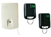
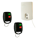
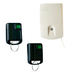
Коротко о товаре: приемник U1HR + 2 передатчика UMB-100-HT
-
В Курске:
Самовывоз: 25.10.2023
Передача в транспортную компанию: 23.10.2023
![]()

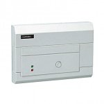
Радиосистема Elmes Electronic U1-HS
-
Основные характеристики
-
Назначение
Для использования в качестве персональной тревожной кнопки в системах охранной сигнализации
-
Рабочая частота
433.92
МГц -
Питание
От сети
-
Напряжение постоянного тока сети
17
В -
Температура эксплуатации
От -20°C до +55°C
-
Материал корпуса
Пластик
-
Цвет
Белый
-
Комплектация
Приемник, передатчик 2 шт
-
Габариты
24 x 46 x 73
мм
-
-
Характеристики Elmes Electronic U1-HS
- Основные характеристики
-
Назначение
Для использования в качестве персональной тревожной кнопки в системах охранной сигнализации
-
Рабочая частота
433.92
МГц - Характеристики питания
-
Питание
От сети
-
Напряжение постоянного тока сети
17
В - Эксплуатационные характеристики
-
Температура эксплуатации
От -20°C до +55°C
- Дополнительные характеристики
-
Материал корпуса
Пластик
-
Цвет
Белый
-
Комплектация
Приемник, передатчик 2 шт
-
Габариты
24 x 46 x 73
мм
Elmes Electronic U1-HS сертифицирован для продажи в России.
Радиосистема Elmes Electronic U1-HS — фото, технические характеристики, условия доставки в Москве и России. Для того, чтобы купить Радиосистема Elmes Electronic U1-HS в интернет-магазине Xcom-shop.ru достаточно заполнить форму онлайн-заказа или
позвонить по телефонам: +7 (495) 799-9669, +7 (800) 200-0069.
Изображения товара, включая цвет, могут отличаться от реального внешнего вида. Комплектация также может быть
изменена производителем без предварительного уведомления. Данное описание и количество товара не является
публичной офертой.

ONE RELAY OUTPUT REMOTE CONTROL SETS WITH
DYNAMIC CODE:
This manual covers the following remote control products operation, installation and
programming:
Equipment
Set Content
Type
U1HS
receiver U1HR + 2 transmitters UMB100HT
U1HSD
receiver U1HSR + 2 transmitters DWB100HT
U1HSL
receiver U1HR + 1 transmitter AN200HT
U1HR – receiver only
U1HR
All above listed products include the same superhet receiver model featuring:
One galvanic separated relay output with NC/NO terminals,
One OC (open collector) transistor type signal output S pulse indicating relay
output switch-over,
Two colour LED indicating state of the relay output,
Highly sensitive and selective superhet receiver,
Memory capacity of up to 112 keyfob remote control transmitters,
KEELOQ® dynamic encoding system.
Receiver Operation Modes
U1HR receiver allows various operation modes depending on selection made by jump-
ers JP1 & JP2 and programming Monostable (pulse) or Bistable (on/off) relay output
mode (step 2 and 3 of programming procedures), as shown in the Table below:
Table of relay output available operation modes
Jumpers
Monostable Mode
State
A. Pressing transmitter button sets receiver’s
JP2 On
(3)
JP1
relay output on for programmed time period.
Next pressing of the button, while output is
on, prolongs set on time of the output.
JP2 Off,
C. Receiver relay output is set on for as long
JP1 On
as transmitter button is pressed and sets off,
(2)
after short delay
, on button release.
JP2 Off
D. Pressing transmitter button 1 sets the out-
JP1 Off
put on. Pressing button 2 sets output off. If
button 2 is not pressed, relay output sets off
after programmed time period
(1)
Output relay Monostable Mode (pulse) or Bistable Mode (on/off) is programmed in
steps 2 and 3 of programming procedures.
(2)
Delayed output set off reduces risk of unwanted interruptions in output set on con-
tinuity, due to interferences caused e.g. electric motors. Precise setting of this
short delay timing is facilitated by programming 8-fold longer time delay of that
needed. Example: to obtain 0.5s set off delay, programmed delay of 4..5s delay
must be made (0.5 x 8=4).
Number of remote control transmitters that can be used in this mode is limited to
20.
(3)
In modes A & B jumper JP1 selects timing of switch-over signal pulses at output S:
jumper On – 0.25s pulse, jumper Off – 0.50s pulse. Longer timing of switch-over
signal pulses is necessary for certain acoustic signalling devices in which shorter
pulses are not recognized properly.
(4)
This mode requires use of hand transmitter with two or more buttons.
KEELOQ® Encoding System
In the system, newly encoded control signal is generated and sent each time transmitter
button is pressed. Receiver monitors code changes and responds to new code signals
only. Once received code will not be accepted second time. This allows protection of
radio transmission signals from deliberate code grabbing and unauthorized use.
Transmitter Memory
As each transmitter generates specific dynamic code, receiver must «learn» and memo-
rize individual coding of every transmitter that will operate with the receiver. Therefore,
receiver’s memory capacity is limited to 112 transmitters. Learning 113
would delete first transmitter in memory, etc. Eliminating lost or stolen transmitters from
receiver’s memory requires deleting all transmitters and learning all remaining transmit-
ters again. Deleting single transmitter from receiver’s memory is possible only with the
use of the transmitter to be deleted (see pt 5 of programming procedures).
Receiver Relay Output
Receiver is equipped with galvanic isolated relay output with NO (normally open) and
NC (normally closed) three wiring terminals – one common. The output switches over
on command received from transmitter. Details are shown on installation diagram in-
cluded in this manual.
Signalling Output S
The receiver features one open collector type (OC) signalling output for connecting to
external acoustic siren or light strobe. The output generates two pulses shorting to re-
ceiver’s ground (-V) on receiver’s relay set ON and one pulse on relay set OFF. Two
pulses are generated also when pressed transmitter’s button is used to prolong set on
timing in monostable mode only (mode A – see Table above). In operation modes D
and E (see Table above), in which button 1 sets output on and button 2 sets output off,
two pulses are generated each time button 1 is pressed and one pulse each time button
2 is pressed.
LED Indication
Receiver is equipped with two colour LED signalling power supply connection and sta-
tus of relay output. It lights red when power is connected and relay output is not activat-
ed. When relay is set on it lights green.
Receiver Installation
Receiver’s place of installation should be dry and away from electromagnetic power
lines, radio transmitters, metal screening and other devices that may cause interference
and reduce operation range. It is recommended to install the receiver well above
floor/ground level and test practical operating range of transmitter-receiver set prior to
firm installation. The level of hand transmitter signals and local unwanted radio interfer-
ence signals can be checked using optional Elmes RFM indicator.
e-mail: elmes@elmes.pl
internet: www.elmes.pl
U1HS, U1HSD, U1HSL, U1HR
Operating Range
100 m
100m
200 m
—
(1)
Bistable Mode
B. Each pressing of remote
transmitter button sets re-
ceiver relay output on and off
alternately (on/off mode).
Not available
E. Pressing transmitter button
1 sets output on. Pressing
button 2 sets output off.
(4)
th
Receiver LED low flashing green in confirms properly performed programming proce-
dure. Fast flashing LED in red indicates programming error. Programming procedure
must be repeated.
1. Learning transmitter(s) to receiver’s memory (maximum 112):
a) Press receiver’s PRG1 switch for less than 2 seconds — LED lights green.
b) Press shortly hand transmitter button once — receiver LED changes to red.
c) Press shortly the same hand transmitter button again.
2. Programming receiver output monostable operation mode (pulse) and output
set on timing:
a) Press receiver’s PRG1 switch — LED lights green and after two seconds changes to
red. Now release the switch.
b) Press hand transmitter button. Relay in the receiver sets on. After required pulse
time has lapsed press hand transmitter button again. Relay in receiver sets off. Af-
ter 2 seconds receiver’s LED starts flashing green confirming end of the procedure.
3. Programming receiver output bistable (on/off) operation mode:
a) Press receiver’s PRG1 switch — LED lights green and after two seconds changes to
red. Now release the switch.
b) Press transmitter button three times with less than 2 seconds intervals. Receiver
LED flashes green confirming end of the procedure.
4. Deleting all transmitters in receiver memory:
Press and hold depressed PRG1 switch for more than 8 seconds. Receiver LED
first lights green. After 2 seconds changes to red and after 6 seconds starts flash-
ing green. Now release the switch. To learn new transmitter(s) follow procedure 1
above.
5. Deleting single transmitter in receiver memory (condition: transmitter to be de-
leted is available):
(1)
a) Press receiver’s PRG1 switch for less than 2 seconds — LED lights green.
b) Press shortly button of the hand transmitter to be deleted — receiver LED changes
to red.
c) Perform one of the following steps:
Press button of any other Elmes Electornic made hand transmitter button, or
temporarily disconnect receiver power supply, or
wait round 30 seconds till receiver exits programming mode.
Correct performing of this procedure is confirmed by LED flashing red (error indication).
Advice 1: Procedures 2, 3 and 5 can be performed with the use of transmitter
learned to the receiver memory.
Advice 2: Time for performing procedures 1 and 5 above is limited to 30 seconds.
If the procedures are not completed within this time period receiver exits
programming mode and error is indicated.
SPECIFICATION
UMB100HT transmitter: radiated power < 5mW, battery: 12V (23A).
AN200HT transmitter: radiated power < 10mW, battery: 9V (6F22).
Receiver:
— dynamic code system KEELOQ® of Microchip Corp. USA,
— transmitter memory capacity: 112 (up to 20 in mode C),
— superhet receiver module with sensitivity: -106 dBm,
— power supply range: 11..17VDC, 50mA.
— operating temperature range from -20 to + 55°C,
— output relay max. power rating: 1A, 120VAC/30VDC,
— monostable output mode timing: from 0,25s up to 4 hours,
— bistable output mode: on/off,
— signal output S (1A/60V max.) OC type,
— sabotage alarm terminals NC type (closed box).
— external dimensions (h/w/l): 24/46/73 mm
Low battery in transmitters is indicated either by its LED flashing (UMB100HT) or dim-
ming and failing to light (AN200HT).
Manufacturer: ELMES ELEKTRONIK, 54-611 Wroclaw, Avicenny 2, PL
tel. +48717845961, fax +48717845963
WARNING! Batteries may contain substances hazardous to human health. Do
not place batteries in fire or household waste. Dispose of old batteries properly
transmitter
in accordance with local law regulations. Used batteries can always be disposed
of at points of electronic waste collection.
Manufacturer’s Limited Warranty
This product carries two year manufacturer’s warranty as from the date of purchase.
The warranty is limited to the replacement of faulty original parts or repair defects of im-
proper manufacture. Damage, misuse or improper handling by the user or installer as
well as any alterations in product’s hardware or software caused by unauthorized per-
son violate warranty obligations and all due repair costs will be charged.
Elmes Electronic shall not be liable for any personal or material damage or loss result-
ing from any of
its products di-
rect,
indirect
or partial use
or
failure
to
operate
properly.
IMPORTANT! Output S must not be directly connected to (+) pole of power supply (see dia-
gram above).
Wyjście S nie może być bezpośrednio łączone do (+) zasilania (patrz schemat).
UWAGA!
PROGRAMMING PROCEDURES
Elmes Elektronik 01.2015. All rights reserved
 В состав прибора входят – радиоприемник и два передатчика — брелка, разработанные для использования в системах дистанционного
радиоуправления и управления доступом.
Оба передатчика (кодер) и прием (декодер) используют KEELOQ — код компании Microchip Technology Inc., USA.
Каждый код передатчика уникален и достаточной длины (разрядности), чтобы ликвидировать угрозу несанкционированного сканирования кода. Система показывает высокий уровень защиты.
Ключи могут быть определены приемником после операции программирования.
Количество передатчиков, используемых в одном наборе и ограничено до 12 – и штук.
При программировании 13 – го брелка стирается 1-й, 14 –го стирается 2 –й и т.д. В случае потери 1-го (или больше) передатчика и необходимости удаления его из системы, необходимо удалить полностью из памяти декодера все брелки и заново прописать каждый.
Радиус действия радиосигнализации будут ограничивать металлические конструкции на пути передатчик приемник.
Инструкция радиосигнализации UMB – 100HS200HS
Приемник обеспечивает полностью программируемые NO/NC релейные выходы и выход S (открытый коллектор) для подключения внешнего сигнального устройства и передачи им 2 –х коротких импульсов при 1-м переключении контактов реле и один импульс при сбросе в исходное состояние.
Встроенный 2 –цветной индикатор обеспечивает необходимый программируемый и релейный статус световыми сигналами.
Наборы поставляются полностью готовыми для эксплуатации с ручным программированием передатчика, и приемник декодера с временными выходными режимами работы и со сбросом времени срабатывание реле.
Изменение временных функций или изменение способа, или приписка нового брелка к приемнику требует выполнения одной или более и программирования описанных далее.
Цена
1 шт — от 650 руб.
Контакты
- Техническая поддержка по тел. +7 (911) 224-87-43.
- Адрес: СПб, метро Сенная Площадь ул. Ефимова дом 1;
- E-mail:dom5min@mail.ru;
- Мы в контакте: https://vk.com/dom_byta_5_minut;
- Работаем без обеда и выходных с 9.00 до 20.00.
Перед программированием надо убедиться, что индикатор приемника имеет красное, если этого нет, необходимо на короткое время отключит
1. Программирование – приписка передатчика (ов) в память приемника:
а нажать кнопку PRO и удерживать менее 3 –х секунд – индикатор светиться зеленым
Б.
Однократно нажать кнопку брелка (любого из 2 –х в наборе) диод изменил свечение на красный
В однократно нажать кнопку брелка еще раз и после 2 –х секунд индикатор изменит цвет четыре раза, что будет означать конец процедуры.
2. Программирование – установка приемника в импульсный режим:
а нажать кнопку PRG и удерживать от 3 –х до 8 –и секунд ( во время удержания индикатор светится зеленым, затем красным)
б нажать однократно кнопку брелка (любого из 2 –х в наборе). Релейные контакты включаются, и это будет означать начало отсчета времени
в когда требуемое время истечет, необходимо нажать кнопку брелка снова.
Релейные контакты выключатся. После 2 –х секунд диод будет означать конец процедуры.
3. Программирование – установка приемника а триггерный режим:
а нажать кнопку PRO и удерживать от 3 –х до 8 –и секунд ( во время удержания диод светится зеленым, затем красным)
б нажать однократно кнопку брелка (любого из 2 –х в наборе) три раза, но с интервалом менее 2 –х секунд. Релейные ключи включатся и выключатся, а индикатор приемника изменит цвет четыре раза, что будет означать конец процедуры.
4. Программирование –стирание всех передатчиков – брелков из памяти приемника:
— нажать кнопку PRG (диод светится зеленым) и удерживать более 8-ми секунд до тех пор, пока индикатор приемника будет менять цвета (четыре раза), что будет означать конец процедуры. Память приемника очистится, но выбранные режимы работы останутся неизменными. Для того чтобы приписать брелок (ки) к памяти приемника смотри п.1.
Предлагаем Вам видео инструкцию программирования пульта от ворот Elmes Electronic.
![]()
© 2003 — 2021 АЛЬЯНС-СБ
© 2003 — 2021 АЛЬЯНС-СБ
Дизайн — студия Алексея Шраймана
Обращаем Ваше внимание, что вся информация, размещенная на данном интернет-сайте, носит информационный характер и не является публичной офертой, определяемой положениями
Статьи 437 (2) ГК РФ.
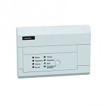
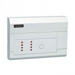
U1-HR – 1-канальный супергетеродинный приемник, 1 релейный выход, 433.92 МГц.
Особенности приемника U1-HR:
- высокозащищенный алгоритм кодирования KEELOQ;
- емкость памяти: 112 передатчиков (20 передатчиков в одном из оперативных режимов);
- чувствительность супергетеродинного приемника: -106дБ;
- задание времени удержания реле в моностабильном (импульсном) режиме: от 0.25сек до 4ч;
- мощность выходных реле: 1А, 120В АС/30В DC;
- бистабильный (переключающий вкл/выкл) режим;
- внешний сигнальный выход S (открытый коллектор): 1А — 60В макс;
- тампер защиты от взлома.
Напряжение питания:
12В (DC)
Температура эксплуатации:
-20…+55 °С
Габаритные размеры:
73×46×24 мм
Инструкция на U1-HR (passport_u1-hr.pdf, 246 Kb) [Скачать]
Приемник U1-HS ELMES, работает на частоте 433 Мгц, одноканальный, питание 12 В DC. Приемник U1-HS является модернизированной версией комплекта UMB-100-HS, устаревшей модели, снятой с производства.
Приемник U1-HS отличается от UMB-100-HS компактым корпусом и дополнительными функциями.
Комплект используется для подключения к системам управления автоматическими воротами или шлагбаумами, для дистанционного управления пультами ELMES. Память приемника рассчитана на запоминание 112 кодов.
Пульты из комплекта уже записаны в память приемника производителем, программирование 113 пульта удалит первый записанный.
Купить дополнительные пульты для приемника Elmes Electronic

Код товара: 0031520
Детектор дыма беспроводной
Код товара: 0031515
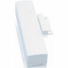
Детектор магнитный беспроводной

Код товара: 0017377
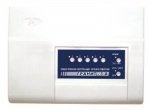
Радиоканальный комбинированный оповещатель (свет + сирена) для EXPRESS GSM вер.2. и PHOTO EXPRESS GSM

Код товара: 0018566
Магнитоконтактный радиоканальный извещатель, 433 МГц, вход для подключения внешних извещателей, порт Touch Memory с трансляцией кода на центральный прибор, дальность действия радиоканала в прямой видимости 250 м.
Код товара: 0018451
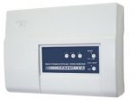
Прибор приёмно-контрольный и управления охранно-пожарный 5 зон, автодозвон, GSM-сигнализация (2 SIM-карты+ГТС), речевые сообщения, РИП, программирование через ПК (USB).
Код товара: 0018442
Прибор приёмно-контрольный и управления охранно-пожарный 3 зоны, автодозвон, GSM-сигнализация (2 SIM-карты+ГТС), речевые сообщения, РИП, программирование через ПК (USB).

Код товара: 0018358
Стационарный GSM блок управления нагрузкой (3,5 кВт). Управление по GSM или брелоком. При отключении 220 В — автономная работа (до 1 года). Подключение до 6 охранных датчиков (движения [Рапид-Р2], открывания [Полюс-Р2]), беспроводной сирены Призма-С. Оповещение хозяина о наличии 220 В, состоянии нагрузки (вкл/выкл), сработке охранных датчиков. Дистанционный контроль баланса, управление нагрузкой, постановка на охрану/снятие. До 6 номеров для оповещения по GSM-каналу (SMS + дозвон).
Код товара: 0018357
Дополнительный элемент питания (батарея). Напряжение: 3В, емкость: 1300мАч.
Код товара: 0017416
CH-8-HR-het, 8-канальный супергетеродинный приемник для беспроводных датчиков и брелков, 8 релейных выходов, индикация разряда батерии, 94х62х29мм
Код товара: 0017414
4-канальный приемник для беспроводных датчиков и брелков, 4 релейных выхода, индикация разряда батерии, 94х62х29мм.

Код товара: 0017452
Одноканальный брелок-передатчик для комплектов и приемников, 37х33х14мм, 100 м в открытой видимости, 433.92 МГц
Код товара: 0017422
Комплект 2-канальный: приемник U2HR + 2 двухкнопочных брелока DWB100HT, 433.92 МГц, 12В DC, память на 104 брелока-передатчика, до 150м, 2 релейных выхода 1А 125В AC/ 30В DC, t -20 +55 °С (модернизированный DWB-100-HS)
Код товара: 0017419
Комплект 1-канальный: приемник U1HR + 2 одноконопочных брелока UMB100HT, 433.92 МГц, 12В DC, 12В DC, память на 112 передатчиков, до 150м, 1 релейный выход 1А 125В AC/ 30В DC, t -20 +55 °С (модернизированный UMB-100-HS)
Код товара: 0017453
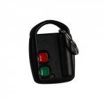
Двухканальный брелок-передатчик, 50х33х13мм, 100 м в открытой видимости, 433.92 МГц
Код товара: 0017455
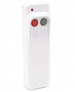
Двухканальный передатчик, 113х33х21мм, 200 м в открытой видимости, 433.92 МГц
Код товара: 0008349
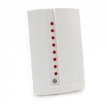
Стационарная контрольная панель со встроенным передатчиком, штыревая антенна, 5 шлейфов ОПС, звуковая и световая сигнализация, тревожное реле, 10-15В, TouchMemory (2 ключа, мастер-ключ), 2 радио-брелка KeeLoq
Код товара: 0008347
Стационарный передатчик-коммуникатор контрольной панели, штыревая антенна, 4 шлейфа ОПС, вход Взят/Снят, 10-15В,
Код товара: 0008326
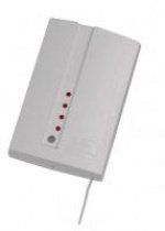
Приемник 8 передатчиков РифРинг-701 и РифСтринг-200, штыревая антенна, звуковая сигнализация, сигнальное реле, (работает с RR-701, RS-200, RP-100/101), -20 +40С, 10-15В, 160х110х32
Код товара: 0008332
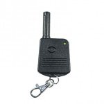
Тревожная радиокнопка большой дальности, встроенная антена, до 2000 м., -20 +40С, 12В
U1-HR – 1-канальный супергетеродинный приемник, 1 релейный выход, 433.92 МГц.
Особенности приемника U1-HR:
- высокозащищенный алгоритм кодирования KEELOQ;
- емкость памяти: 112 передатчиков (20 передатчиков в одном из оперативных режимов);
- чувствительность супергетеродинного приемника: -106дБ;
- задание времени удержания реле в моностабильном (импульсном) режиме: от 0.25сек до 4ч;
- мощность выходных реле: 1А, 120В АС/30В DC;
- бистабильный (переключающий вкл/выкл) режим;
- внешний сигнальный выход S (открытый коллектор): 1А — 60В макс;
- тампер защиты от взлома.
Напряжение питания:
12В (DC)
Температура эксплуатации:
-20…+55 °С
Габаритные размеры:
73×46×24 мм
Инструкция на U1-HR (passport_u1-hr.pdf, 246 Kb) [Скачать]
ONE RELAY OUTPUT REMOTE CONTROL SETS WITH
DYNAMIC CODE:
This manual covers the following remote control products operation, installation and
programming:
Equipment
Set Content
Type
U1HS
receiver U1HR + 2 transmitters UMB100HT
U1HSD
receiver U1HSR + 2 transmitters DWB100HT
U1HSL
receiver U1HR + 1 transmitter AN200HT
U1HR – receiver only
U1HR
All above listed products include the same superhet receiver model featuring:
One galvanic separated relay output with NC/NO terminals,
One OC (open collector) transistor type signal output S pulse indicating relay
output switch-over,
Two colour LED indicating state of the relay output,
Highly sensitive and selective superhet receiver,
Memory capacity of up to 112 keyfob remote control transmitters,
KEELOQ® dynamic encoding system.
Receiver Operation Modes
U1HR receiver allows various operation modes depending on selection made by jump-
ers JP1 & JP2 and programming Monostable (pulse) or Bistable (on/off) relay output
mode (step 2 and 3 of programming procedures), as shown in the Table below:
Table of relay output available operation modes
Jumpers
Monostable Mode
State
A. Pressing transmitter button sets receiver’s
JP2 On
(3)
JP1
relay output on for programmed time period.
Next pressing of the button, while output is
on, prolongs set on time of the output.
JP2 Off,
C. Receiver relay output is set on for as long
JP1 On
as transmitter button is pressed and sets off,
(2)
after short delay
, on button release.
JP2 Off
D. Pressing transmitter button 1 sets the out-
JP1 Off
put on. Pressing button 2 sets output off. If
button 2 is not pressed, relay output sets off
after programmed time period
(1)
Output relay Monostable Mode (pulse) or Bistable Mode (on/off) is programmed in
steps 2 and 3 of programming procedures.
(2)
Delayed output set off reduces risk of unwanted interruptions in output set on con-
tinuity, due to interferences caused e.g. electric motors. Precise setting of this
short delay timing is facilitated by programming 8-fold longer time delay of that
needed. Example: to obtain 0.5s set off delay, programmed delay of 4..5s delay
must be made (0.5 x 8=4).
Number of remote control transmitters that can be used in this mode is limited to
20.
(3)
In modes A & B jumper JP1 selects timing of switch-over signal pulses at output S:
jumper On – 0.25s pulse, jumper Off – 0.50s pulse. Longer timing of switch-over
signal pulses is necessary for certain acoustic signalling devices in which shorter
pulses are not recognized properly.
(4)
This mode requires use of hand transmitter with two or more buttons.
KEELOQ® Encoding System
In the system, newly encoded control signal is generated and sent each time transmitter
button is pressed. Receiver monitors code changes and responds to new code signals
only. Once received code will not be accepted second time. This allows protection of
radio transmission signals from deliberate code grabbing and unauthorized use.
Transmitter Memory
As each transmitter generates specific dynamic code, receiver must «learn» and memo-
rize individual coding of every transmitter that will operate with the receiver. Therefore,
receiver’s memory capacity is limited to 112 transmitters. Learning 113
would delete first transmitter in memory, etc. Eliminating lost or stolen transmitters from
receiver’s memory requires deleting all transmitters and learning all remaining transmit-
ters again. Deleting single transmitter from receiver’s memory is possible only with the
use of the transmitter to be deleted (see pt 5 of programming procedures).
Receiver Relay Output
Receiver is equipped with galvanic isolated relay output with NO (normally open) and
NC (normally closed) three wiring terminals – one common. The output switches over
on command received from transmitter. Details are shown on installation diagram in-
cluded in this manual.
Signalling Output S
The receiver features one open collector type (OC) signalling output for connecting to
external acoustic siren or light strobe. The output generates two pulses shorting to re-
ceiver’s ground (-V) on receiver’s relay set ON and one pulse on relay set OFF. Two
pulses are generated also when pressed transmitter’s button is used to prolong set on
timing in monostable mode only (mode A – see Table above). In operation modes D
and E (see Table above), in which button 1 sets output on and button 2 sets output off,
two pulses are generated each time button 1 is pressed and one pulse each time button
2 is pressed.
LED Indication
Receiver is equipped with two colour LED signalling power supply connection and sta-
tus of relay output. It lights red when power is connected and relay output is not activat-
ed. When relay is set on it lights green.
Receiver Installation
Receiver’s place of installation should be dry and away from electromagnetic power
lines, radio transmitters, metal screening and other devices that may cause interference
and reduce operation range. It is recommended to install the receiver well above
floor/ground level and test practical operating range of transmitter-receiver set prior to
firm installation. The level of hand transmitter signals and local unwanted radio interfer-
ence signals can be checked using optional Elmes RFM indicator.
e-mail: elmes@elmes.pl
internet: www.elmes.pl
U1HS, U1HSD, U1HSL, U1HR
Operating Range
100 m
100m
200 m
—
(1)
Bistable Mode
B. Each pressing of remote
transmitter button sets re-
ceiver relay output on and off
alternately (on/off mode).
Not available
E. Pressing transmitter button
1 sets output on. Pressing
button 2 sets output off.
(4)
th
Receiver LED low flashing green in confirms properly performed programming proce-
dure. Fast flashing LED in red indicates programming error. Programming procedure
must be repeated.
1. Learning transmitter(s) to receiver’s memory (maximum 112):
a) Press receiver’s PRG1 switch for less than 2 seconds — LED lights green.
b) Press shortly hand transmitter button once — receiver LED changes to red.
c) Press shortly the same hand transmitter button again.
2. Programming receiver output monostable operation mode (pulse) and output
set on timing:
a) Press receiver’s PRG1 switch — LED lights green and after two seconds changes to
red. Now release the switch.
b) Press hand transmitter button. Relay in the receiver sets on. After required pulse
time has lapsed press hand transmitter button again. Relay in receiver sets off. Af-
ter 2 seconds receiver’s LED starts flashing green confirming end of the procedure.
3. Programming receiver output bistable (on/off) operation mode:
a) Press receiver’s PRG1 switch — LED lights green and after two seconds changes to
red. Now release the switch.
b) Press transmitter button three times with less than 2 seconds intervals. Receiver
LED flashes green confirming end of the procedure.
4. Deleting all transmitters in receiver memory:
Press and hold depressed PRG1 switch for more than 8 seconds. Receiver LED
first lights green. After 2 seconds changes to red and after 6 seconds starts flash-
ing green. Now release the switch. To learn new transmitter(s) follow procedure 1
above.
5. Deleting single transmitter in receiver memory (condition: transmitter to be de-
leted is available):
(1)
a) Press receiver’s PRG1 switch for less than 2 seconds — LED lights green.
b) Press shortly button of the hand transmitter to be deleted — receiver LED changes
to red.
c) Perform one of the following steps:
Press button of any other Elmes Electornic made hand transmitter button, or
temporarily disconnect receiver power supply, or
wait round 30 seconds till receiver exits programming mode.
Correct performing of this procedure is confirmed by LED flashing red (error indication).
Advice 1: Procedures 2, 3 and 5 can be performed with the use of transmitter
learned to the receiver memory.
Advice 2: Time for performing procedures 1 and 5 above is limited to 30 seconds.
If the procedures are not completed within this time period receiver exits
programming mode and error is indicated.
SPECIFICATION
UMB100HT transmitter: radiated power < 5mW, battery: 12V (23A).
AN200HT transmitter: radiated power < 10mW, battery: 9V (6F22).
Receiver:
— dynamic code system KEELOQ® of Microchip Corp. USA,
— transmitter memory capacity: 112 (up to 20 in mode C),
— superhet receiver module with sensitivity: -106 dBm,
— power supply range: 11..17VDC, 50mA.
— operating temperature range from -20 to + 55°C,
— output relay max. power rating: 1A, 120VAC/30VDC,
— monostable output mode timing: from 0,25s up to 4 hours,
— bistable output mode: on/off,
— signal output S (1A/60V max.) OC type,
— sabotage alarm terminals NC type (closed box).
— external dimensions (h/w/l): 24/46/73 mm
Low battery in transmitters is indicated either by its LED flashing (UMB100HT) or dim-
ming and failing to light (AN200HT).
Manufacturer: ELMES ELEKTRONIK, 54-611 Wroclaw, Avicenny 2, PL
tel. +48717845961, fax +48717845963
WARNING! Batteries may contain substances hazardous to human health. Do
not place batteries in fire or household waste. Dispose of old batteries properly
transmitter
in accordance with local law regulations. Used batteries can always be disposed
of at points of electronic waste collection.
Manufacturer’s Limited Warranty
This product carries two year manufacturer’s warranty as from the date of purchase.
The warranty is limited to the replacement of faulty original parts or repair defects of im-
proper manufacture. Damage, misuse or improper handling by the user or installer as
well as any alterations in product’s hardware or software caused by unauthorized per-
son violate warranty obligations and all due repair costs will be charged.
Elmes Electronic shall not be liable for any personal or material damage or loss result-
ing from any of
its products di-
rect,
indirect
or partial use
or
failure
to
operate
properly.
IMPORTANT! Output S must not be directly connected to (+) pole of power supply (see dia-
gram above).
Wyjście S nie może być bezpośrednio łączone do (+) zasilania (patrz schemat).
UWAGA!
PROGRAMMING PROCEDURES
Elmes Elektronik 01.2015. All rights reserved