Главная » Инструкции » Автоматика для ворот » FAAC
![]()
FAAC E045 — Инструкция по установке и эксплуатации (RU) в формате pdf. Руководства по установке, настройке и эксплуатации оборудования.
Дата добавления: 20.01.2018
Размер файла: 1.5 Mb
Формат файла: pdf
Просмотров: 2223
Загрузок: 292
Дополнительная информация
По данному материалу пока нет информации.
Отзывы и комментарии
Отзывы и комментарии к материалу «FAAC E045 — Инструкция по установке и эксплуатации (RU)».
Ответить 13.05.2021 13:15
Владимир
Инструкция по установке приводов
Кто вы? человек робот
E045
4
732786 — Rev. A_1
Р
УССКИЙ
ОГЛАВЛЕНИЕ
ДЕКЛАРАЦИЯ
О
СООТВЕТСТВИИ
. . . . . . . . . . . . . . . . . . . . . . .2
МЕРЫ
ПРЕДОСТОРОЖНОСТИ
И
РЕКОМЕНДАЦИИ
ПО
УСТАНОВКЕ
. . . . . . . ..3
1.
ТЕХНИЧЕСКИЕ
ХАРАКТЕРИСТИКИ
. . . . . . . . . . . . . . . . . . . . ..5
2.
ПРАВИЛА
УСТАНОВКИ
. . . . . . . . . . . . . . . . . . . . . . . . . …6
3.
СХЕМА
ПЛАТЫ
. . . . . . . . . . . . . . . . . . . . . . . . . . . . …6
4.
ЭЛЕКТРИЧЕСКИЕ
ПОДКЛЮЧЕНИЯ
. . . . . . . . . . . . . . . . . . . . ..8
4.1 J1 —
ПЕРВИЧНОЕ
СЕТЕВОЕ
ПИТАНИЕ
. . . . . . . . . . . . . . . . . . 8
4.2 J2 —
ПРИВОДЫ
И
СИГНАЛЬНАЯ
ЛАМПА
. . . . . . . . . . . . . . . . . .8
4.3 J3-
РАЗЪЕМЫ
ВХОДОВ
УСТРОЙСТВ
УПРАВЛЕНИЯ
И
БЕЗОПАСНОСТИ
. . . …9
4.4 J9-
ПИТАНИЕ
ДОП
.
УСТРОЙСТВ
. . . . . . . . . . . . . . . . . . . . . 10
4.5 J11-
РАЗЪЕМЫ
ВЫХОДОВ
КОНТРОЛЬНОЙ
ЛАМПЫ
/
ЭЛЕКТРОЗАМКА
. . . . ..10
4.6 J10-
ШИННЫЕ
УСТРОЙСТВА
BUS-2EASY . . . . . . . . . . . . . . . . . 11
Фотоэлементы
BUS-2EASY . . . . . . . . . . . . . . . . . . . . . . . …11
АДРЕСАЦИЯ
ФОТОЭЛЕМЕНТОВ
BUS-2EASY . . . . . . . . . . . . . . . …12
Подключение
фотоэлементов
BUS-2EASY . . . . . . . . . . . . . . . . . .12
Энкодер
BUS-2EASY . . . . . . . . . . . . . . . . . . . . . . . . . . .13
Подключение
—
Адресация
Энкодера
BUS-2EASY . . . . . . . . . . . . . . .13
4.7 J5 —
ПОДКЛЮЧЕНИЕ
МОДУЛЯ
XF . . . . . . . . . . . . . . . . . . . . .14
5.
ПРОГРАММИРОВАНИЕ
. . . . . . . . . . . . . . . . . . . . . . . . . …15
5.1
БАЗОВОЕ
ПРОГРАММИРОВАНИЕ
. . . . . . . . . . . . . . . . . . . . 16
5.2
РАСШИРЕННОЕ
ПРОГРАММИРОВАНИЕ
. . . . . . . . . . . . . . . . . .21
5.3
УСТАНОВКА
ШИННЫХ
УСТРОЙСТВ
BUS-2EASY: . . . . . . . . . . . . . .24
5.3.1
ЗАПОМИНАНИЕ
ШИННЫХ
УСТРОЙСТВ
BUS-2EASY: . . . . . . . . . . .24
Проверка
зарегистрированных
на
плате
устройств
. . . . . . . . . . . . . . 25
5.4
НАСТРОЙКА
ВРЕМЕНИ
РАБОТЫ
. . . . . . . . . . . . . . . . . . . . .26
5.5
ПРОВЕРКА
АВТОМАТИКИ
. . . . . . . . . . . . . . . . . . . . . . . .27
6.
КОДИРОВАНИЕ
ПУЛЬТОВ
РАДИОУПРАВЛЕНИЯ
. . . . . . . . . . . . . . …28
6.1
КОДИРОВАНИЕ
РАДИОПУЛЬТОВ
SLH/SLH LR . . . . . . . . . . . . . . ..28
6.2
ЗАПИСЬ
ПУЛЬТОВ
LC/RC (
ТОЛЬКО
433
МГЦ
) . . . . . . . . . . . . . . . 29
6.2.1
УДАЛЕННАЯ
ЗАПИСЬ
РАДИОБРЕЛОКОВ
LC/RC . . . . . . . . . . . . .30
6.3
ЗАПИСЬ
ПУЛЬТОВ
DS . . . . . . . . . . . . . . . . . . . . . . . . . 30
6.4
УДАЛЕНИЕ
ПУЛЬТОВ
ИЗ
ПАМЯТИ
. . . . . . . . . . . . . . . . . . . …31
7.
ВВОД
В
ЭКСПЛУАТАЦИЮ
. . . . . . . . . . . . . . . . . . . . . . . . ..32
7.1
ПРОВЕРКА
СИСТЕМЫ
ПО
СВЕТОДИОДАМ
. . . . . . . . . . . . . . . …32
8.
СИГНАЛЫ
ОШИБОК
И
АВАРИЙНЫЕ
СИГНАЛЫ
. . . . . . . . . . . . . . . 33
8.1
ОШИБКИ
. . . . . . . . . . . . . . . . . . . . . . . . . . . . . . …33
8.2
АВАРИЙНЫЕ
СИГНАЛЫ
. . . . . . . . . . . . . . . . . . . . . . . . 34
9.
ПОИСК
НЕИСПРАВНОСТЕЙ
. . . . . . . . . . . . . . . . . . . . . . . …34
10.
КОНФИГУРАЦИОННЫЙ
ФАЙЛ
— J8 USB. . . . . . . . . . . . . . . . . . .35
11.
ЛОГИКИ
ФУНКЦИОНИРОВАНИЯ
. . . . . . . . . . . . . . . . . . . . . .38

E045
5
732786 — Rev. A_1
Р
УССКИЙ
БЛОК
УПРАВЛЕНИЯ
E045
Мы
благодарим
Вас
за
Ваш
выбор
!
Компания
FAAC
уверена
,
что
эксплуатационные
качества
выбранной
продукции
смогут
полностью
удовлетворить
Ваши
потребности
.
Вся
наша
продукция
является
результатом
многолетнего
опыта
в
сфере
автоматических
систем
.
1.
ТЕХНИЧЕСКИЕ
ХАРАКТЕРИСТИКИ
ПРЕДНАЗНАЧЕН
ДЛЯ
управления
распашными
воротами
,
регулирующими
автомобильный
и
пешеходный
доступ
.
Во
время
программирования
есть
возможность
выбрать
разные
логики
функционирования
Содержит
два
уровня
программирования
с
помощью
кнопок
и
дисплея
:
БАЗОВЫЙ
И
РАСШИРЕННЫЙ
Первичное
сетевое
питание
C
импульсным
источником
питания
230
В
~ ± 15%
50/60
Гц
Поглощаемая
мощность
Stand By = 4
Вт
;
МАКС
. —
около
800
Вт
Максимальная
нагрузка
на
мотор
800
Вт
Питание
доп
.
устройств
24
В
«
Макс
.
нагрузка
на
доп
.
устройства
+24
МАКС
. 500
мА Макс
.
нагрузка
на
устройства
,
подключаемые
к
2-
проводной
шине
BUS-2EASY — 500
мА
Замок
(FAAC) 12
В
~ / 24
В
«
Диапазон
рабочих
температур
:
от
-20°C
до
+55°C
Предохранители
F1 =2,5
А
Время
работы
Самонастраивается
непосредственно
через
настройки
— (
Макс
. 4
мин
и
10
сек
.)
Время
паузы
Программируемое
(
от
0
до
9
мин
.
и
50
сек
)
Мощность
привода
Программируемая
на
50
уровнях
Разъемные
входы
Модуль
XF433/868, USB
Клеммные
входы
Сетевое
питание
, BUS-2EASY, OPEN-A, OPEN-B,
STOP
Клеммные
выходы
Сигнальная
лампа
,
двигатели
,
электрозамок
, W.L,
питание
доп
.
устройств
Таб
.
ТЕХНИЧЕСКИЕ
ХАРАКТЕРИСТИКИ

E045
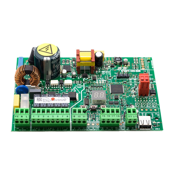
8
732786 — Rev. A_1
MAX
500 mA
{
C1
C2
J11
J3
J9
J2
J1
15 16 17 18
20 21
9 10 11
PE N L
1 2 3 4 5 6 7 8
AC MAIN
PE
N
L
M1
1
2
3
W.L.
21
LOCK
20
LAMP
7
8
24V
3W
230V~
MAX 60W
Mot1
Mot2
COM OP CL
OP-A OP-B STOP
—
15
—
16
+
17
+
18
9
10
11
24V
M2
4
5
6
COM OP CL
230V~ ±15%
50/60 Hz
12V~
24V
J1
J2
J3
J11
J9
Ë
*
Ë
*
Р
УССКИЙ
4.
ЭЛЕКТРИЧЕСКИЕ
ПОДКЛЮЧЕНИЯ
4.1 J1 —
ПЕРВИЧНОЕ
СЕТЕВОЕ
ПИТАНИЕ
PE
Заземление
Для
корректного
функционирования
,
и м п у л ь с н ы й
и с т о ч н и к
п и т а н и я
д о л ж е н
б ы т ь
подсоединен
к
заземляющему
п р о в о д н и к у
у с т а н о в к и
.
Установить
термомагнитный
дифференциальный
выключатель
э л е к т р о п и т а н и я
с и с т е м ы
с
соответствующим
порогом
срабатывания
.
N
Питание
от
90
до
260 V~
Нейтраль
L
Питание
от
90
до
260 V~
Фаза
4.2 J2 —
ПРИВОДЫ
И
СИГНАЛЬНАЯ
ЛАМПА
1
M1 — COM
Привод
1:
Общий
M1 =
открывается
первая
створка
или
единственная
створка
M2
=
открывается
вторая
створка
—
НЕ
используется
на
одностворчатых
воротах
Проверить
правильность
кабельной
проводки
и
направление
вращения
приводов
(
см
. 6.4
НАСТРОЙКА
ВРЕМЕНИ
РАБОТЫ
)
2
M1 — OP
Привод
1:
Фаза
закрытия
3
M1 — CL
Привод
1:
Фаза
закрытия
4
M2 — COM
Привод
2:
Общий
5
M2 — OP
Привод
2:
Фаза
открытия
6
M2 — CL
Привод
2:
Фаза
закрытия
7
LAMP
Выход
подключения
сигнальной
лампы
(
Макс
. 60
Вт
)
8
привод
для
одностворчатых
ворот
или
первой
створки
при
открытии
(
закрывается
второй
)
OPEN A
Полное
открытие
ворот
(
контакт
N.O.)
OPEN B
Частичное
открытие
ворот
(
контакт
N.O.)
STOP
Остановка
ворот
(
контакт
N.C.)
ë*
синий
или
серый
-
Contents
-
Table of Contents
-
Troubleshooting
-
Bookmarks
Quick Links
Related Manuals for FAAC E045
Summary of Contents for FAAC E045
-
Page 1
E045 E045… -
Page 2
CE DECLARATION OF CONFORMITY The manufacturer Company name: FAAC S.p.A. Soc. Unipersonale Address: Via Calari, 10 — 40069 Zola Predosa BOLOGNA — ITALY hereby declares that the following product: Description: control board Model: E045 conforms to the essential safety requirements of the following ECC directives:… -
Page 3: Warnings For The Installer
17. FAAC S.p.A. declines all liability as concerns sa- 6. FAAC S.p.A. declines all liability caused by impro- per use or use other than that for which the fety and efficient operation of the automated automated system was intended.
-
Page 4: Table Of Contents
7. START-UP ……………………..32 7.1 CHECKING THE LEDs ………………….32 8. SIGNALLING ERRORS AND ALARMS …………….33 8.1 ERRORS ……………………..33 8.2 ALARMS ……………………..34 9. TROUBLESHOOTING ………………….34 10. MANAGING THE CONFIGURATION FILE – J8 USB …………35 11. FUNCTION LOGICS ………………….38 E045 732786 — Rev.C…
-
Page 5: Technical Specifications
Accessories power supply +24V MAX 500 mA BUS-2EASY MAX 500 mA MAX. accessories current LOCK (FAAC) 12 V~ / 24 V » from -20°C to +55°C Operating ambient temperature F1 = F5 A Power supply safety fuses Self-learned through SETUP — (Max 4 min and 10 sec)
-
Page 6: Preparing For Installation
-/R2 SW1 SW2 SW3 DL10 DL10 DL10 1 2 3 4 5 6 7 8 9 10 11 15 16 17 18 20 21 PE N L USB-A W.L. LOCK AC MAIN LAMP OP-A OP-B STOP E045 732786 — Rev.C…
-
Page 7
OPEN A Channel 2 — (Partial Opening) OPEN B HOST USB-A for Mass Memories connector » +24V Accessories power supply connector BUS-2EASY Device connector Indicator Light/ Electric Lock output connector Motor and power supply safety fuse E045 732786 — Rev.C… -
Page 8: Electrical Connections
M2 — COM Common contact motor 2 of motor rotation, (see 6.4 TIME LEAR- NING — SETUP) M2 — OP OP phase motor 2 M2 — CL CL phase motor 2 LAMP Flashing lamp connection (MAX 60 W) E045 732786 — Rev.C…
-
Page 9: J3 — Command And Safety Devices Inputs
To install more than one STOP device, connect the N.C. contacts in series (see related Fig.). If stop devices are NOT connected, jumper terminals STOP and GND. Fig. e.g.: Connecting 2 N.O. contacts in parallel. Fig. e.g.: Connecting 2 N.C. contacts in series. E045 732786 — Rev.C…
-
Page 10: J9 — Accessories Power Supply
Electric lock (12 V~ or 24 V » ) position the leaf is in). LOCK operated 2 sec before opening of leaf 1 When BUS-2EASY encoder is enabled, the electric lock is operated before opening, only if the leaf is closed position. E045 732786 — Rev.C…
-
Page 11: Bus-2Easy Accessories
Opening safety devices Should use of traditional photocells be required, you must use a BUS Interface Module to be connected to the BUS-2EASY J10 terminal. For further information, refer to the BUS Interface Module instructions. E045 732786 — Rev.C…
-
Page 12: Address Assignment Of Bus-2Easy Photocells
OPEN PULSE (1 pair) Connection of BUS-2EASY photocells For connecting you have to use two cables without polarity (see the specific device instructions). DL1 = Alignment DL2 = BUS-2EASY status/ Power supply DS1 = Programming Dip-switches BUS-2EASY E045 732786 — Rev.C…
-
Page 13: Bus-2Easy Encoder
S800 ENC BUS-2EASY BUS-2EASY M1 : 2 LEDs on M2 : 1 LED on Note: to correct the coupling of the · · encoder with motor M1 or M2, swap both wires on the terminals. E045 732786 — Rev.C…
-
Page 14: J5 — Xf Module Rapid Connector
Plug-in rapid connector dedicated to OMNIDEC 2-channel decoding module. ALWAYS cut off power to the board BE- FORE inserting/removing the module. DL11 DL12 DL11 DL12 5V 24V E 24V ERROR 24 E E RR 4V E 4V E ERROR E045 732786 — Rev.C…
-
Page 15: Programming
TO SAVE DISPLAYED TO VISUALIZE THE FUNCTION DESIRED ONE THE PROGRAMMING AUTOMATED SYSTEM APPEARS +/R1 -/R2 STATUS OTHERWISE SELECT TO EXIT +/R1 THE PROGRAMMING WITHOUT SAVING +/R1 THE FUNCTION IS DISPLAYED UNTIL YOU HOLD E045 732786 — Rev.C…
-
Page 16: Basic Programming Functions
OPEN B inputs will automatically be changed to CLOSE. , if you choose a logic that does not require the use of CLOSE inputs, these inputs will change to OPEN B. For a description of how the logics operate, see the related paragraph. E045 732786 — Rev.C…
-
Page 17
SETUP with two motors or by re- turning to one motor. If a SETUP is performed with two motors and later only one is used, the board will not signal an error. Only the motor connected to input M1 will move. E045 732786 — Rev.C… -
Page 18
Next the value 59, the viewing changes to minutes and tenths of a second (separated by a decimal point) and time is adjusted in 10-second steps up to the maximum value of minutes. e.g.: if the display shows , the time is 1 min and 20 sec E045 732786 — Rev.C… -
Page 19
) until the button is held down MOTOR 1 dead-man DRIVE mode +/R1 OPENS (visualising ) until the button is held down -/R2 CLOSES (visualising ) until the button is held down WORK TIME LEARNING (SETUP): See the related paragraph. E045 732786 — Rev.C… -
Page 20
WARNING If power is lost to the board prior to confirmation (step 2.), all changes made will be lost. You can EXIT programming at any time: press and hold F and then also — to switch directly to -/R2 E045 732786 — Rev.C… -
Page 21: Advanced Programming Functions
LEAF 2 DECELERATION (visualised only with the function You can adjust the deceleration space as a percentage of the total travel of leaf 2. Adjustable from %, in 1% steps. = no deceleration = minimum deceleration space = maximum deceleration space E045 732786 — Rev.C…
-
Page 22
ADDITIONAL OPERATING TIME (displayed only if function You can add a work time at the end of movement. Adjustable from sec in 1 sec steps. This time is not considered when calculating the deceleration per- centage. E045 732786 — Rev.C… -
Page 23
WARNING If power is lost to the board prior to confirmation (step 2.), all changes made will be lost. You can EXIT programming at any time: press and hold F and then also — to switch directly to -/R2 E045 732786 — Rev.C… -
Page 24: Bus-2Easy Device Installation
ON = correctly connected and entered OPEN photocell: ON = entered and engaged Closing photocells: ON = entered and engaged Fig. Visualising the BUS-2EASY status in the function : each segment of the display shows one type of device. E045 732786 — Rev.C…
-
Page 25: Checking The Securing Devices Entered On The Board
— That there are no more than one device in the system with the same Rapid blinking (blink every 0.5 sec) address. — Calling error (number > or < the connected BUS devices). — FAIL SAFE error on the BUS device. Board in Sleep mode (if used). E045 732786 — Rev.C…
-
Page 26: Time Learning — Setup
Leaf 2 will stop as soon as it reaches the pulse as soon as leaf 2 reaches the contact contact point. If there is no mechanical point. stop, stop the leaf movement at the de- sired point by sending an OPEN A pulse. E045 732786 — Rev.C…
-
Page 27: Testing The Automated System
Once installation and programming is completed, ensure that the system is operating correctly. Be especially careful that the safety devices operate correctly and ensure that the system complies with all current safety regulations. Close the cover in the provided seat with gasket. E045 732786 — Rev.C…
-
Page 28: Memorising The Radio Code
Ensure that there are no obstacles (by people or things) during the automated system movement. 5” 5” 2 x 2” > 30 cm 2” P1 + P2 > 5” +/R1 +/R1 1” 1” DL11 20” 20” RADIO 1 E045 732786 — Rev.C…
-
Page 29: Memorising Lc/Rc Radio Controls (Only 433 Mhz)
When the 20 sec have elapsed, the LED will turn off, indicating that the procedure has been completed. 4. To add other radio controls, repeat the procedure from point 1. > 30 cm > 5” +/R1 +/R1 1” DL11 20” 20” 20” 20” RADIO 1 E045 732786 — Rev.C…
-
Page 30: Lc/Rc
6. To add other radio controls with the same code, set the 12 dip-switches according to the same com- bination as the already memorised radio control. > 30 cm > 5” +/R1 +/R1 1” DL11 20” 20” RADIO 1 E045 732786 — Rev.C…
-
Page 31: Deleting The Radio Controls
Once rapid flashing has stopped, LEDs DL11 and DL12 will go on steady, confirming the cancellation of all the radio codes (OPEN A and OPEN B/CLOSE) from the board memory. 2. Release -/R2 . The LEDs will go off, indicating correct cancellation. -/R2 E045 732786 — Rev.C…
-
Page 32: Start-Up
Led ERROR — FLASHING = there is an alarm in progress (situation that does not compromise gate operation) — see “ALARMS”. ON STEADY = there is an error in progress (situation that blocks operation until the cause of the fault has been eliminated). See “ERRORS”. E045 732786 — Rev.C…
-
Page 33: Signalling Errors And Alarms
SETUP Motor 1 encoder fault Check the connections or replace motor 1 encoder Motor 2 encoder fault Check the connections or replace motor 2 encoder Incorrect memory data Repeat BUS-2EASY device entry and/or re-program the board E045 732786 — Rev.C…
-
Page 34: Alarms
• Check that the photocell wiring and alignment is correct • Check that there is no OPEN signal active The gate will not close • Check which function logic has been chosen (automatic or semi-automatic) E045 732786 — Rev.C…
-
Page 35: Managing The Configuration File — J8 Usb
In addition, the names and extensions of the various files must be as follows: • E045SW.cod — The board SOFTWARE update file • E045.prg — The board PROGRAMMING update file • E045.rad — The board RADIO update file These files will be generated, named and placed as shown in fig. in case of transfer from the board to the USB memory.
-
Page 36
E045.prg RADIO CODE LIST UPGRADE: This function lets you update the radio code list on the board (file E045.rad). If + and — are pressed simultaneously for at least 5 seconds, you will access the board update. -
Page 37
USB memory. = Copy: the radio codes file will be saved in the format E045.rad by overwriting any other radio codes file present with the same name, so it can be used to upgrade another system. -
Page 38: Function Logics
Logic with two separate An OPEN-A pulse During motion, the (OPEN-B commands: a held during closing opens, photocells reverse inputs become OPEN-A pulse opens; a CLOSE pulse during CLOSE) a held CLOSE pulse opening closes closes E045 732786 — Rev.C…
-
Page 39
NO EFFECT STOPPED OPPOSITE DIRECTION CLOSES OPEN CLOSE OPEN CLOSE OPEN STOPS ALWAYS CLOSES AFTER STOP DISABLED DISABLED DISABLED SAVES CLOSE if the cycle began with OPEN-B, opens totally operation can be modified by programming E045 732786 — Rev.C… -
Page 40
NO EFFECT NO EFFECT NO EFFECT NO EFFECT OPEN STOPPED CLOSES OPEN CLOSE OPEN CLOSE CLOSE DISABLED DISABLED DISABLED DISABLED if the cycle began with OPEN-B, opens totally operation can be modified by programming E045 732786 — Rev.C… -
Page 41
NO EFFECT NO EFFECT NO EFFECT NO EFFECT OPEN STOPPED OPENS CLOSES OPEN CLOSE OPEN CLOSE CLOSE DISABLED DISABLED DISABLED DISABLED if the cycle began with OPEN-B, opens totally operation can be modified by programming E045 732786 — Rev.C… -
Page 42
NO EFFECT NO EFFECT NO EFFECT NO EFFECT OPEN STOPPED OPENS CLOSES OPEN CLOSE OPEN CLOSE CLOSE DISABLED DISABLED DISABLED DISABLED if the cycle began with OPEN-B, opens totally operation can be modified by programming E045 732786 — Rev.C… -
Page 44
FAAC S.p.A. Soc. Unipersonale Via Calari, 10 — 40069 Zola Predosa BOLOGNA — ITALY Tel. +39 051 61724 — Fax +39 051 758518 www.faac.it — www.faacgroup.com E045 732786 — Rev.C…
Faac E045 – плата управления для 2х моторов 230В, входы фотоэлементов BUS 2EASY, радиоразъем XF.
Функции:
- порядок программирования: с ЖК-дисплеем;
- режимы работы «автоматический-полуавтоматический»;
- интенсивность использования «в присутствии оператора»;
- безопасность при открытии и закрытии;
- управление логикой систем защиты;
- створка повернута/неполное открытие;
- электрозамок 12В (открытие и/или закрытие);
- сигнальная лампа;
- замедление по таймеру;
- электронное обнаружение препятствий;
- замедление со считыванием позиции створки;
- возможность подключения внешнего таймера;
- возможность задержки закрытия створки;
- возможность задержки открытия створки;
- регулировка усилия (отдельно для каждого двигателя);
- отказоустойчивость (автоматическая проверка фотодатчиков);
- сигнализация состояния входов: светодиоды/дисплей;
- диагностика;
- цикл запоминания позиций открытия и закрытия;
- проверка приводов;
- предварительное мигание (5 сек);
- BUS 2easy;
- OmniDEC.
Инструкция на Faac E045 (passport_faac_e045.pdf, 1,589 Kb) [Скачать]
Предложите, как улучшить StudyLib
(Для жалоб на нарушения авторских прав, используйте
другую форму
)
Ваш е-мэйл
Заполните, если хотите получить ответ
Оцените наш проект
1
2
3
4
5