Fluke 87V; 80 Series V — Industrial Multimeter Manual
Introduction
Read «Safety Information» before you use the Meter.
Except where noted, the descriptions and instructions in this manual apply to Series V Models 83 and 87 multimeters (hereafter referred to as «the Meter»).
Model 87 appears in all illustrations.
Safety Information
The Meter complies with:
- EN61010-1:2001
- ANSI/ISA S82.01-2004
- CAN/CSA C22.2 No. 1010.1:2004
- UL610101-1
- Measurement Category III, 1000V, Pollution Degree 2
- Measurement Category IV, 600V, Pollution Degree 2
In this manual, a Warning identifies conditions and actions that pose hazards to the user. A Caution identifies conditions and actions that may damage the Meter or the equipment under test.
Electrical symbols used on the Meter and in this manual are explained in Table 1.
To avoid possible electric shock or personal injury, follow these guidelines:
- Use this Meter only as specified in this manual or the protection provided by the Meter might be impaired.
- Do not use the Meter if it is damaged. Before you use the Meter, inspect the case. Look for cracks or missing plastic. Pay particular attention to the insulation surrounding the connectors.
- Make sure the battery door is closed and latched before operating the Meter.
- Replace the battery as soon as the battery indicator (
 ) appears.
 - Remove test leads from the Meter before opening the battery door.
- Inspect the test leads for damaged insulation or exposed metal. Check the test leads for continuity. Replace damaged test leads before you use the Meter.
- Do not apply more than the rated voltage, as marked on the Meter, between the terminals or between any terminal and earth ground.
- Never operate the Meter with the cover removed or the case open.
- Use caution when working with voltages above 30 V ac rms, 42 V ac peak, or 60 V dc. These voltages pose a shock hazard.
- Use only the replacement fuses specified by the manual.
- Use the proper terminals, function, and range for measurements.
- Avoid working alone.
- When measuring current, turn off circuit power before connecting the Meter in the circuit. Remember to place the Meter in series with the circuit.
- When making electrical connections, connect the common test lead before connecting the live test lead; when disconnecting, disconnect the live test lead before disconnecting the common test lead.
- Do not use the Meter if it operates abnormally. Protection may be impaired. When in doubt, have the Meter serviced.
- Do not operate the Meter around explosive gas, vapor, or dust.
- Use only a single 9 V battery, properly installed in the Meter case, to power the Meter.
- When servicing the Meter, use only specified replacement parts.
- When using probes, keep fingers behind the finger guards on the probes.
- Do not use the Low Pass Filter option to verify the presence of hazardous voltages. Voltages greater than what is indicated may be present. First, make a voltage measurement without the filter to detect the possible presence of hazardous voltage. Then select the filter function.
To avoid possible damage to the Meter or to the equipment under test, follow these guidelines:
- Disconnect circuit power and discharge all highvoltage capacitors before testing resistance, continuity, diodes, or capacitance.
- Use the proper terminals, function, and range for all measurements.
- Before measuring current, check the Meter’s fuses.
(See «Fuse Test» in the Users Manual on the 80 Series V User Manual CD.)
Table 1. Electrical Symbols
 |
AC (Alternating Current) |  |
Earth ground |
 |
DC (Direct Current) |  |
Fuse |
| |
Hazardous voltage |  |
Conforms to European Union directives. |
| |
Risk of Danger. Important information. See Manual. |  |
Conforms to relevant Canadian Standards Association directives. |
 |
Battery. Low battery when displayed. |  |
Double insulated |
 |
Continuity test or continuity beeper tone. |  |
Capacitance |
| CAT III | IEC Overvoltage Category III CAT III equipment is designed to protect against transients in equipment in fixed-equipment installations, such as distribution panels, feeders and short branch circuits, and lighting systems in large buildings. |
CAT IV | IEC Overvoltage Category IV CAT IV equipment is designed to protect against transients from the primary supply level, such as an electricity meter or an overhead or underground utility service. |
 |
Underwriters Laboratories |  |
Diode |
 |
Inspected and licensed by TÜV Product Services. |
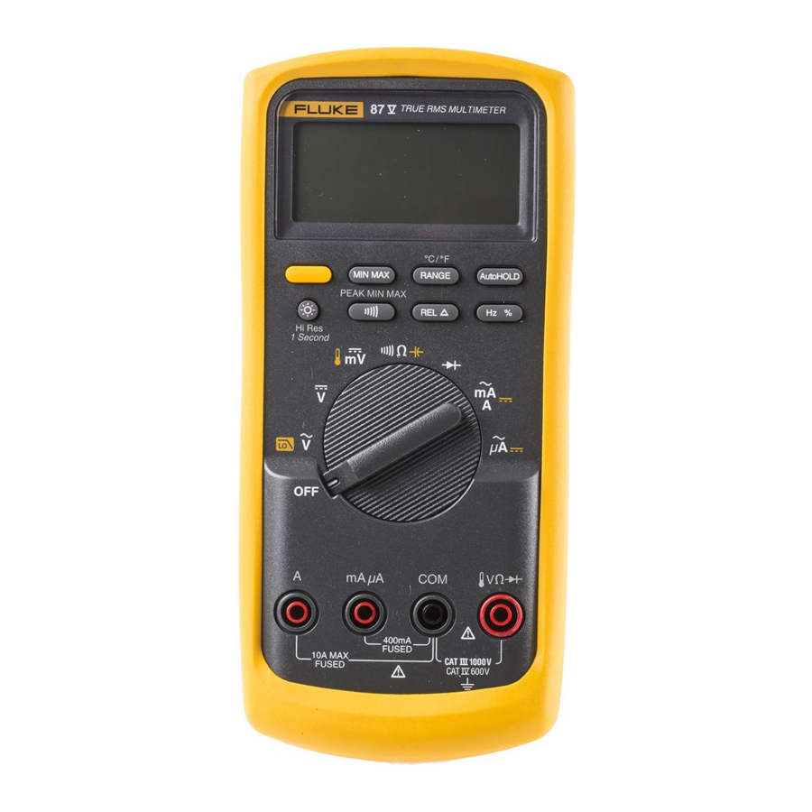
The Meter’s Features
Tables 2 through 5 briefly describe the Meter’s features.
Table 2. Inputs
| Terminal | Description |
| A | Input for 0 A to 10.00 A current (20 A overload for 30 seconds maximum), current frequency, and duty cycle measurements. |
| mA μA | Input for 0 μA to 400 mA current measurements (600 mA for 18 hrs.) and current frequency and duty cycle. |
| COM | Return terminal for all measurements |
 |
Input for voltage, continuity, resistance, diode, capacitance, frequency, temperature (87), and duty cycle measurements. |
Table 3. Rotary Switch Positions
| Switch Position | Function |
| Any Position | When the Meter is turned on, the Meter model number briefly appears on the display. |
 |
AC voltage measurement Press  for low pass filter ( for low pass filter ( ) (87 only). ) (87 only). |
 |
DC voltage measurement |
 |
600 mV dc voltage range Press for temperature ( ) (87 only). ) (87 only). |
 |
Press  for continuity test. for continuity test. Resistance measurement Resistance measurement Press for capacitance measurement. |
 |
Diode test |
 |
AC current measurements from 0 mA to 10.00 A Press for dc current measurements, from 0 mA to 10.00 A. |
 |
AC current measurements from 0 μA to 6000 μA Press for dc current measurements from 0 μA to 6000 μA. |
Table 4. Pushbuttons
| Button | Switch Position | Function |
 (Yellow) |
|
|
 |
|
|
 |
|
|
 |
|
|
 |
Any switch position |
Turns the backlight on, makes it brighter, and turns it off. For Model 87, hold |
 |
|
|
 (Relative mode) |
|
|
 |
Any switch position except diode test Power-up |
Press Starts the frequency counter. Press again to enter duty cycle mode. Enables the Meter’s high impedance mode when the mV dc function is used. |


 » until
 » until
 Display Features

Table 5. Display Features
| Number | Feature | Indication |
| 1 |  |
Polarity indicator for the analog bar graph. |
 |
Positive or negative slope indicator for Hz/duty cycle triggering. | |
| 2 |  |
The continuity beeper is on. |
| 3 |  |
Relative (REL) mode is active. |
| 4 |  |
Smoothing is active. |
| 5 |  |
Indicates negative readings. In relative mode, this sign indicates that the present input is less than the stored reference. |
| 6 |  |
Indicates the presence of a high voltage input. Appears if the input voltage is 30 V or greater (ac or dc). Also appears in low pass filter mode. Also appears in cal, Hz, and duty cycle modes. |
| 7 |  |
AutoHOLD is active. |
| 8 |  |
Display Hold is active. |
| 9 |  |
Indicates the Meter is in Peak Min Max mode and the response time is 250 μs (87 only). |
| 10 |
MAX MIN AVG |
Indicators for minimum-maximum recording mode. |
| 11 |  |
Low pass filter mode (87 only). See «Low Pass Filter (87). |
| 12 |  |
The battery is low. To avoid false readings, which could lead to possible electric shock or personal injury, replace the battery as soon as the battery indicator appears. |
| 13 |
|
|
| 14 | °C, °F | Degrees Celsius, Degrees Fahrenheit |
| 15 | 610000 mV | Displays selected range |
| 16 | HiRes | The Meter is in high resolution (Hi Res) mode. HiRes=19,999 |
| 17 | Auto | The Meter is in autorange mode and automatically selects the range with the best resolution. |
| Manual | The Meter is in manual range mode. | |
| 18 |  |
The number of segments is relative to the full-scale value of the selected range. In normal operation 0 (zero) is on the left. The polarity indicator at the left of the graph indicates the polarity of the input. The graph does not operate with the capacitance, frequency counter functions, temperature, or peak min max. For more information, See «Bar Graph» in the Users Manual located on the 80 Series V User Manual CD. The bar graph also has a zoom function, as described under «Zoom Mode». |
| — |  |
Overload condition is detected. |


Display Messages
 |
Replace the battery immediately. |
 |
In the capacitance function, too much electrical charge is present on the capacitor being tested. |
 |
Invalid EEPROM data. Have Meter serviced. |
 |
Invalid calibration data. Calibrate Meter. |
 |
|
 |
Invalid model. Have Meter serviced. |
 |
Open thermocouple is detected. |
Main Options
Power-Up Options
Holding a button down while turning the Meter on activates a power-up option. Table 4 includes the power-up options.
Automatic Power-Off
The Meter automatically turns off if you do not turn the rotary switch or press a button for 30 minutes. If MIN MAX Recording is enabled, the Meter will not power off. To disable automatic power-off, refer to Table 4.
Input Alert™ Feature
If a test lead is plugged into the mA/μA or A terminal, but the rotary switch is not set to the correct current position, the beeper warns you by making a chirping sound and the display flashes ««. This warning is intended to stop you from attempting to measure voltage, continuity, resistance, capacitance, or diode values when the leads are plugged into a current terminal.
Placing the probes across (in parallel with) a powered circuit when a lead is plugged into a current terminal can damage the circuit you are testing and blow the Meter’s fuse. This can happen because the resistance through the Meter’s current terminals is very low, so the Meter acts like a short circuit.
Low Pass Filter (87)
The 87 is equipped with an ac low pass filter. When measuring ac voltage or ac frequency, press  to activate the low pass filter mode (
 ). The Meter continues measuring in the chosen ac mode, but now the signal diverts through a filter that blocks unwanted voltages above 1 kHz, refer to Figure 2. The lower frequency voltages pass with reduced accuracy to the measurement below 1 kHz. The low pass filter can improve measurement performance on composite sine waves that are typically generated by inverters and variable frequency motor drives.
To avoid possible electric shock or personal injury, do not use the Low Pass Filter option to verify the presence of hazardous voltages. Voltages greater than what is indicated may be present. First, make a voltage measurement without the filter to detect the possible presence of hazardous voltage. Then select the filter function.
Note
In Low Pass Mode, the Meter goes to manual mode. Select ranges by pressing the RANGE button. Autoranging is not available in Low Pass Mode.")
Bar Graph
The analog bar graph functions like the needle on an analog meter, but without the overshoot. The bar graph updates 40 times per second. Because the graph responds 10 times faster than the digital display, it is useful for making peak and null adjustments and observing rapidly changing inputs. The graph is not shown for capacitance, frequency counter functions, temperature, or peak min max.
The number of lit segments indicates the measured value and is relative to the full-scale value of the selected range.
In the 60 V range, for example, the major divisions on the scale represent 0, 15, 30, 45, and 60 V. An input of -30 V lights the negative sign and the segments up to the middle of the scale.
The bar graph also has a zoom function, as described under «Zoom
Mode» in the Users Manual located on the 80 Series V User Manuals CD.
Table 6. MIN MAX Functions
| Button | MIN MAX Function |
 |
Enter MIN MAX recording mode. The Meter is locked in the range displayed before you entered MIN MAX mode. (Select the desired measurement function and range before entering MIN MAX.) The Meter beeps each time a new minimum or maximum value is recorded. |
| (while in MIN MAX mode) |
Step through maximum (MAX), minimum (MIN), and average (AVG) and present values. |
 PEAK MIN MAX |
Model 87 only: Select 100 ms or 250 μs response time. (The 250 μs response time is indicated by  the display.) Stored values are erased. The present and AVG (average) values are not available when 250 μs is selected. the display.) Stored values are erased. The present and AVG (average) values are not available when 250 μs is selected. |
 |
Stop recording without erasing stored values. Press again to resume recording. |
| (hold for 1 second) |
Exit MIN MAX mode. Stored values are erased. The Meter stays in the selected range. |
AutoHOLD Mode
To avoid electrical shock or personal injury, do not use AutoHOLD mode to determine that circuits are without power. The AutoHOLD mode will not capture unstable or noisy readings.
The AutoHOLD mode captures the present reading on the display. When a new, stable reading is detected, the Meter beeps and displays the new reading. To enter or exit AutoHOLD mode, press .
Relative Mode
Selecting relative mode (  ) causes the Meter to zero the display and store the present reading as the reference for subsequent measurements. The Meter is locked into the range selected when you pressed . Press again to exit this mode.
In relative mode, the reading shown is always the difference between the present reading and the stored reference value. For example, if the stored reference value is 15.00 V and the present reading is 14.10 V, the display shows -0.90 V.
Maintenance
To avoid electrical shock or personal injury, repairs or servicing not covered in this manual should be performed only by qualified personnel as described in the 80 Series V Service Information.
General Maintenance
Periodically wipe the case with a damp cloth and mild detergent. Do not use abrasives or solvents.
Fuse Test
If a test lead is plugged into the mA/μA or A terminal and the rotary switch is turned to a non-current function, the Meter chirps and flashes « » if the fuse associated with that current terminal is good. If the Meter does not chirp or flash ««, the fuse is bad and must be replaced.
To avoid electrical shock or personal injury, remove the test leads and any input signals before replacing the battery or fuses. To prevent damage or injury, install ONLY specified replacement fuses with the amperage, voltage, and speed ratings shown in Replacement Parts in the Users Manual located on the 80 Series V User Manual CD.
Specifications
Maximum Voltage between any Terminal and Earth Ground:
1000 V rms
Fuse Protection for mA or μA inputs:
44/100 A, 1000 V FAST Fuse
Fuse Protection for A input:
11 A, 1000 V FAST Fuse
Display:
Digital: 6000 counts updates 4/sec; (Model 87 also has 19,999 counts in high-resolution mode).
Analog Bargraph:
33 segments, updates 40/sec. Frequency: 19,999 counts, updates 3/sec at > 10 Hz
Temperature:
Operating: -20°C to +55°C; Storage: -40°C to +60°C
Altitude:
Operating: 2000 m; Storage: 10,000 m
Temperature Coefficient:
0.05 x (specified accuracy)/ °C (< 18°C or > 28°C)
Electromagnetic Compatibility:
In an RF field of 3 V/m total accuracy = specified accuracy + 20 counts Except: 600 μA dc range total accuracy=specified accuracy + 60 counts. Temperature not specified.
Relative Humidity:
0% to 90% (0°C to 35°C); 0% to 70% (35°C to 55°C)
Battery Type:
9 V zinc, NEDA 1604 or 6F22 or 006P
Battery Life:
400 hrs typical with alkaline (with backlight off)
Vibration: \
Per MIL-PRF-28800 for a Class 2 instrument
Shock:
1 Meter drop per IEC 61010-1:2001
Size (HxWxL):
1.25 in x 3.41 in x 7.35 in (3.1 cm x 8.6 cm x 18.6 cm)
Size with Holster and Flex-Stand:
2.06 in x 3.86 in x 7.93 in (5.2 cm x 9.8 cm x 20.1 cm)
Weight:
12.5 oz (355 g)
Weight with Holster and Flex-Stand:
22.0 oz (624 g)
Safety:
Complies with ANSI/ISA S82.01-2004, CSA 22.2 No. 1010.1:2004 to 1000 V Overvoltage Category III, IEC 664 to 600 V Overvoltage Category IV. UL listed to UL61010-1. Licensed by TÜV to EN61010-1.
IP Rating:
30
Detailed Specifications
For all detailed specifications:
Accuracy is given as ±([% of reading] + [number of least significant digits]) at 18°C to 28°C, with relative humidity up to 90%, for a period of one year after calibration.
For Model 87 in the 4 ½-digit mode, multiply the number of least significant digits (counts) by 10. AC conversions are ac-coupled and valid from 3% to 100% of range. Model 87 is true rms responding. AC crest factor can be up to 3 at full scale, 6 at half scale. For non-sinusoidal wave forms add -(2% Rdg + 2% full scale) typical, for a crest factor up to 3.
Table 7. Model 87 AC Voltage Function Specifications
| Function | Range | Resolution | Accuracy | |||||
 |
600.0 mV | 0.1 mV | 45 – 65 Hz | 30 – 200 Hz | 200 – 440 Hz | 440 Hz — 1 kHz | 1 — 5 kHz | 5 — 20 kHz[1] |
| ± (0.7% + 4) | ± (1.0% + 4) | ± (2.0% + 4) | ± (2.0% + 20) | |||||
| 6.000 V | 0.001 V | ± (0.7% + 2) | ||||||
| 60.00 V | 0.01 V | |||||||
| 600.0 V | 0.1 V | ± (2.0% + 4) [3] | unspecified | |||||
| 1000 V | 1 V | unspecified | unspecified | |||||
| Low pass filter |
Same as 45 — 65 Hz |
± (1.0% + 4) |
+1% + 4 -6% — 4[5] |
unspecified | unspecified | unspecified | ||
|
Table 8. Model 83 AC Voltage Function Specifications
| Function | Range | Resolution | Accuracy | ||
 |
600.0 mV 6.000 V 60.00 V 600.0 V 1000 V |
0.1 mV 0.001 V 0.01 V 0.1 V 1 V |
50 Hz — 60 Hz | 30 Hz — 1 kHz | 1 kHz — 5 kHz |
|
± (0.5% + 4) ± (0.5% + 2) ± (0.5% + 2) ± (0.5% + 2) ± (0.5% + 2) |
± (1.0% + 4) ± (1.0% + 4) ± (1.0% + 4) ± (1.0% + 4) ± (1.0% + 4) |
± (2.0% + 4) ± (2.0% + 4) ± (2.0% + 4) ± (2.0% + 4)2 unspecified |
|||
|
Table 9. DC Voltage, Resistance, and Conductance Function Specifications
| Function | Range | Resolution | Accuracy | |
| Model 83 | Model 87 | |||
 |
6.000 V 60.00 V 600.0 V 1000 V |
0.001 V 0.01 V 0.1 V 1 V |
± (0.1% + 1) ± (0.1% + 1) ± (0.1% + 1) ± (0.1% + 1) |
± (0.05% + 1) ± (0.05% + 1) ± (0.05% + 1) ± (0.05% + 1) |
 |
600.0 mV | 0.1 mV | ± (0.3% + 1) | ± (0.1% + 1) |
|
nS |
600.0 Ω 6.000 kΩ 60.00 kΩ 600.0 kΩ 6.000 MΩ 50.00 MΩ 60.00 nS |
0.1 Ω 0.001 kΩ 0.01 kΩ 0.1 kΩ 0.001 MΩ 0.01 MΩ 0.01 nS |
± (0.4% + 2)1 ± (0.4% + 1) ± (0.4% + 1) ± (0.7% + 1) ± (0.7% + 1) ± (1.0% + 3)2 ± (1.0% + 10)1 |
± (0.2% + 2)1 ± (0.2% + 1) ± (0.2% + 1) ± (0.6% + 1) ± (0.6% + 1) ± (1.0% + 3)2 ± (1.0% + 10)1 |
|

Table 10. Temperature Specifications (87 Only)
| Temperature | Resolution | Accuracy1,2 |
|
-200°C to +1090°C -328°F to +1994°F |
0.1°C 0.1°F |
1% + 10 1% + 18 |
|
Table 11. Current Function Specifications
| Function | Range | Resolution | Accuracy | Burden Voltage (typical) | |
| Model 831 | Model 872, 3 | ||||
 (45 Hz to 2 kHz) (45 Hz to 2 kHz) |
60.00 mA 400.0 mA6 6.000 A 10.00 A4 |
0.01 mA 0.1 mA 0.001 A 0.01 A |
± (1.2% + 2)5 ± (1.2% + 2)5 ± (1.2% + 2)5 ± (1.2% + 2)5 |
± (1.0% + 2) ± (1.0% + 2) ± (1.0% + 2) ± (1.0% + 2) |
1.8 mV/mA 1.8 mV/mA 0.03 V/A 0.03 V/A |
 |
60.00 mA 400.0 mA6 6.000 A 10.00 A4 |
0.01 mA 0.1 mA 0.001 A 0.01 A |
± (0.4% + 4) ± (0.4% + 2) ± (0.4% + 4) ± (0.4% + 2) |
± (0.2% + 4) ± (0.2% + 2) ± (0.2% + 4) ± (0.2% + 2) |
1.8 mV/mA 1.8 mV/mA 0.03 V/A 0.03 V/A |
| μA ~ (45 Hz to 2 kHz) |
600.0 μA 6000 μA |
0.1 μA 1 μA |
± (1.2% + 2)5 ± (1.2% + 2)5 |
± (1.0% + 2) ± (1.0% + 2) |
100 μV/μA 100 μV/μA |
 |
600.0 μA 6000 μA |
0.1 μA 1 μA |
± (0.4% + 4) ± (0.4% + 2) |
± (0.2% + 4) ± (0.2% + 2) |
100 μV/μA 100 μV/μA |
|
Table 12. Capacitance and Diode Function Specifications
| Function | Range | Resolution | Accuracy |
 |
10.00 nF 100.0 nF 1.000 μF 10.00 μF 100.0 μF 9999 μF |
0.01 nF 0. 1 nF 0.001 μF 0.01 μF 0.1 μF 1 μF |
± (1% + 2)1 ± (1% + 2)1 ± (1% + 2) ± (1% + 2) ± (1% + 2) ± (1% + 2) |
 |
3.000 V | 0.001 V | ± (2% + 1) |
|
Table 13. Frequency Counter Specifications
| Function | Range | Resolution | Accuracy |
| Frequency (0.5 Hz to 200 kHz, pulse width > 2 μs) |
199.99 1999.9 19.999 kHz 199.99 kHz > 200 kHz |
0.01 Hz 0.1 Hz 0.001 kHz 0.01 kHz 0.1 kHz |
± (0.005% + 1) ± (0.005% + 1) ± (0.005% + 1) ± (0.005% + 1) unspecified |
Table 14. Frequency Counter Sensitivity and Trigger Levels
| Input Range1 | Minimum Sensitivity (RMS Sine wave) | Approximate Trigger Level (DC Voltage Function) |
|
| 5 Hz — 20 kHz | 0.5 Hz — 200 kHz | ||
|
600 mV dc 600 mV ac 6 V 60 V 600 V 1000 V |
70 mV (to 400 Hz) 150 mV 0.3 V 3 V 30 V 100 V |
70 mV (to 400 Hz) 150 mV 0.7 V 7 V (≤140 kHz) 70 V (≤14.0 kHz) 200 V (≤1.4 kHz) |
40 mV ⎯ 1.7 V 4 V 40 V 100 V |
| Duty Cycle Range | Accuracy | ||
| 0.0 to 99.9% | Within ± (0.2% per kHz + 0.1%) for rise times < 1 μs. | ||
|
Table 15. Electrical Characteristics of the Terminals
| Function | Overload Protection1 | Input Impedance (nominal) | Common Mode Rejection Ratio (1 kΩ unbalance) |
Normal Mode Rejection | ||||||
 |
1000 V rms | 10 MΩ < 100 pF | > 120 dB at dc, 50 Hz or 60 Hz | > 60 dB at 50 Hz or 60 Hz | ||||||
 |
1000 V rms | 10 MΩ < 100 pF | > 120 dB at dc, 50 Hz or 60 Hz | > 60 dB at 50 Hz or 60 Hz | ||||||
 |
1000 V rms | 10 MΩ < 100 pF (ac-coupled) | > 60 dB, dc to 60 Hz | |||||||
| Open Circuit Test Voltage | Full Scale Voltage | Typical Short Circuit Current | ||||||||
| To 6.0 MΩ | 50 MΩ or 60 nS | 600 Ω | 6 k | 60 k | 600 k | 6 M | 50 M | |||
 |
1000 V rms | < 7.9 V dc | < 4.1 V dc | < 4.5 V dc | 1 mA | 100 μA | 10 μA | 1μA | 1 μA | 0.5 μA |
 |
1000 V rms | < 7.9 V dc | 3.000 V dc | 1.0 mA typical | ||||||
|
Table 16. MIN MAX Recording Specifications
| Model | Nominal Response | Accuracy |
| 83 | 100 ms to 80% | Specified accuracy ± 12 counts for changes > 200 ms in duration (± 40 counts in ac with beeper on) |
| 87 |
100 ms to 80% (dc functions) 120 ms to 80 % 250 μs (peak) |
Specified accuracy ± 12 counts for changes > 200 ms in duration Specified accuracy ± 40 counts for changes > 350 ms and inputs > 25% of range Specified accuracy ± 100 counts for changes > 250 μs in duration |
|
To contact Fluke, call one of the following telephone numbers:
- USA: 1-888-44-FLUKE (1-888-443-5853)
- Canada: 1-800-36-FLUKE (1-800-363-5853)
- Europe: +31 402-675-200
- Japan: +81-3-3434-0181
- Singapore: +65-738-5655
- Anywhere in the world: +1-425-446-5500
- USA Service: 1-888-99-FLUKE (1-888-993-5853)
Or, visit Fluke’s Web site at www.fluke.com.
To register your product, visit register.fluke.com
© 2004, 2008 Fluke Corporation.
All rights reserved. Printed in U.S.A.
Specifications are subject to change without notice.
All product names are trademarks of their respective companies.

Documents / Resources
References
Download manual
Here you can download full pdf version of manual, it may contain additional safety instructions, warranty information, FCC rules, etc.
Download Fluke 87V; 80 Series V — Industrial Multimeter Manual

®
80 Series V
Multimeters
Руководство пользователя
May 2004 Rev.2, 11/08 (Russian)
©2004, 2008 Fluke Corporation. All rights reserved.
Specifications are subject to change without notice.
All product names are trademarks of their respective companies.
Перед вами файл pdf, где представлена инструкция (руководство) на русском для FLUKE 87v. Вы можете скачать ее либо изучить в онлайн режиме.
Подробные сведения об инструкции:
Устройство из раздела: мультиметр
Бренд-производитель: FLUKE
Наименование модели: FLUKE 87v
Язык: Руководство на русском языке
Файл: pdf
Размер файла: 1,76 MB
Скачать инструкцию к HARPER HDT2-1110
ЗАГРУЗИТЬ
Просмотр инструкции онлайн
ОГРАНИЧЕННАЯ ГАРАНТИЯ И ОГРАНИЧЕНИЕ ОТВЕТСТВЕННОСТИ
Для каждого продукта Fluke гарантируется отсутствие дефектов материалов и изготовления при нормальном использовании и обслуживании. Срок
гарантии один год, начиная с даты поставки. На запчасти, ремонт оборудования и услуги предоставляется гарантия 90 дней. Эта гарантия действует
только для первоначального покупателя или конечного пользователя, являющегося клиентом авторизованного реселлера Fluke, и не
распространяется на предохранители, одноразовые батареи и на любые продукты, которые, по мнению Fluke, неправильно или небрежно
использовались, были изменены, загрязнены или повреждены вследствие несчастного случая или ненормальных условий работы или обработки.
Fluke гарантирует, что программное обеспечение будет работать в соответствии с его функциональными характеристиками в течение 90 дней, и что
оно правильно записано на исправных носителях. Fluke не гарантирует, что программное обеспечение будет работать безошибочно и без остановки.
Авторизованные реселлеры Fluke расширят действие этой гарантии на новые и неиспользованные продукты только для конечных пользователей, но
они не уполномочены расширять условия гарантии или вводить новые гарантийные обязательства от имени Fluke. Гарантийная поддержка
предоставляется, только если продукт приобретен на авторизованной торговой точке Fluke, или покупатель заплатил соответствующую
международную цену. Fluke оставляет за собой право выставить покупателю счет за расходы на ввоз запасных/сменных частей, когда продукт,
приобретенный в одной стране, передается в ремонт в другой стране.
Гарантийные обязательства Fluke ограничены по усмотрению Fluke выплатой покупной цены, бесплатным ремонтом или заменой неисправного
продукта, который возвращается в авторизованный сервисный центр Fluke в течение гарантийного периода.
Для получения гарантийного сервисного обслуживания обратитесь в ближайший авторизованный сервисный центр Fluke за информацией о праве на
возврат, затем отправьте продукт в этот сервисный центр с описанием проблемы, оплатив почтовые расходы и страховку (ФОБ пункт назначения).
Fluke не несет ответственности за повреждения при перевозке. После осуществления гарантийного ремонта продукт будет возвращен покупателю с
оплаченной перевозкой (ФОБ пункт назначения). Если Fluke определяет, что неисправность вызвана небрежностью, неправильным использованием,
загрязнением, изменением, несчастным случаем или ненормальными условиями работы и обработки, включая электрическое перенапряжение из-за
несоблюдения указанных допустимых значений, или обычным износом механических компонентов, Fluke определит стоимость ремонта и начнет
работу после получения разрешения. После ремонта продукт будет возвращен покупателю с оплаченной перевозкой, и покупателю будет выставлен
счет за ремонт и транспортные расходы при возврате (ФОБ пункт отгрузки).
ЭТА ГАРАНТИЯ ЯВЛЯЕТСЯ ЕДИНСТВЕННОЙ И ИСКЛЮЧИТЕЛЬНОЙ И ЗАМЕНЯЕТ ВСЕ ОСТАЛЬНЫЕ ГАРАНТИИ, ПРЯМЫЕ ИЛИ СВЯЗАННЫЕ,
ВКЛЮЧАЯ, ПОМИМО СЛУЧАЙНЫЕ ИЛИ КОСВЕННЫЕ ПОВРЕЖДЕНИЯ ИЛИ УЩЕРБ, ВКЛЮЧАЯ ПОТЕРЮ ДАННЫХ, ЯВЛЯЮЩИЕСЯ РЕЗУЛЬТАТОМ
КАКИХ-ЛИБО ДЕЙСТВИЙ ИЛИ МЕТОДОВ.
Поскольку некоторые страны не допускают ограничения срока связанной гарантии или исключения и ограничения случайных или косвенных
повреждений, ограничения этой гарантии могут относиться не ко всем покупателям. Если какое-либо положение этой гарантии признано судом или
другим директивным органом надлежащей юрисдикции недействительным или не имеющим законной силы, такое признание не повлияет на
действительность или законную силу других положений.
Fluke Corporation
P.O. Box 9090
Everett, WA 98206-9090
США
Fluke Europe B.V.
P.O. Box 1186
5602 BD Eindhoven
Нидерланды
11/99
-
Page 1
87V MAX Digital Multimeter Users Manual October 2019 © 2019 Fluke Corporation. All rights reserved. Specifications are subject to change without notice. All product names are trademarks of their respective companies. Fluke-Direct info@Fluke-Direct.ca 1.800.561.8187… -
Page 2
Lifetime Limited Warranty Each Fluke 20, 70, 80, 170, 180 and 280 Series DMM will be free from defects in material and workmanship for its lifetime. As used herein, “lifetime” is defined as seven years after Fluke discontinues manufacturing the product, but the warranty period shall be at least ten years from the date of purchase. -
Page 3: Table Of Contents
Table of Contents Title Page Introduction ……………………1 How to Contact Fluke ………………… 1 Safety Information ………………….1 Features ……………………. 2 Automatic Power-Off ………………..9 Input Alert™ Feature ………………..9 Power-Up Options ………………… 9 How to Make Measurements ………………11 AC and DC Voltage Measurements …………….
-
Page 4
87V MAX Users Manual Capacitance Measurements ………………19 Diode Tests ………………….. 20 AC or DC Current Measurements …………….22 Frequency Measurements ………………25 Duty Cycle Measurements ………………27 How to Determine Pulse Width …………….. 28 Bargraph ……………………28 Zoom Mode (Power Up Option Only) ……………. 29 Uses for the Zoom Mode ……………… -
Page 5
Contents (continued) Frequency ……………………. 45 Frequency Counter Sensitivity and Trigger Levels ………… 45 Duty Cycle (Vdc and mVdc) ………………46 Input Characteristics ………………..46 MIN MAX Recording ………………..47 Fluke-Direct info@Fluke-Direct.ca 1.800.561.8187… -
Page 6: Introduction
Introduction XW Warning Read “Safety Information” before using the Meter. The 87V MAX (the Product or Meter) is a True-rms Digital Multimeter. In addition, the 87V MAX measures temperature using a type-K thermocouple. Fluke-Direct info@Fluke-Direct.ca 1.800.561.8187…
-
Page 7: Features
87V MAX Users Manual Features Tables 1 through 4 briefly describe the features of the Meter. Table 1. Inputs gaq112.emf Terminal Description Input for 0 A to 10.00 A current (10 — 20 A overload for 30 seconds maximum), current frequency, and duty cycle measurements.
-
Page 8
(yellow) Press for dc current measurements, from 0 mA to 10.00 A. AC current measurements from 0 μA to 6000 μA (yellow) for dc current measurements from 0 μA to 6000 μA. Press Fluke-Direct info@Fluke-Direct.ca 1.800.561.8187… -
Page 9
87V MAX Users Manual Table 3. Pushbuttons Switch Button Function Position Selects capacitance Selects temperature Selects ac low-pass filter function (Yellow) Switches between dc and ac current Switches between dc and ac current Any switch Switches between the ranges available for the selected function. -
Page 10
To return to the 3-1/2 digit mode, hold down for one second. HiRes=19,999 Any switch Starts recording of minimum and maximum values. Steps the display through MAX, MIN, AVG position (average), and present readings. Cancels MIN MAX (hold for 1 second) Fluke-Direct info@Fluke-Direct.ca 1.800.561.8187… -
Page 11
87V MAX Users Manual Table 3. Pushbuttons (cont.) Button Switch Position Function Any switch Stores the present reading as a reference for subsequent readings. The display is position zeroed, and the stored reading is subtracted from all subsequent readings. -
Page 12
bargraph. See Low-pass Filter. Positive or negative slope indicator Trig± for Hz/duty cycle triggering. The continuity beeper is on. Relative (REL) mode is active. Smoothing is active. Fluke-Direct info@Fluke-Direct.ca 1.800.561.8187… -
Page 13
87V MAX Users Manual Table 4. Display Features (cont.) Number Feature Indication Number Feature Indication Degrees Celsius, Degrees °C, °F Warning: To Low battery. XW Fahrenheit prevent false readings, which could lead to possible electric 610000 mV Displays selected range … -
Page 14: Automatic Power-Off
Meter acts like a short circuit. switch position does not correspond to the terminal being used. Power-Up Options Holding a button down while turning the Meter on activates a power-up option. Table 5 describes power-up options. Fluke-Direct info@Fluke-Direct.ca 1.800.561.8187…
-
Page 15
The Meter reads “” until is released. Enables the Meter’s calibration mode and prompts for a password. The Meter reads “” and enters calibration mode. See 87V MAX Calibration Information Enables the Meter’s smoothing feature. The Meter reads “” until … -
Page 16: How To Make Measurements
60.00 V, 600.0 V, and 1000 V. The select the 600.0 mV dc range, turn the rotary switch to mV. Refer to Figure 2 to measure ac or dc voltage. gaq102.emf Figure 2. AC and DC Voltage Measurements Fluke-Direct info@Fluke-Direct.ca 1.800.561.8187…
-
Page 17: Zero Input Behavior Of True-Rms Meter
87V MAX Users Manual Low-Pass Filter When measuring voltage, the Meter acts approximately like a 10-MΩ (10,000,000 Ω) impedance in parallel with The Meter is equipped with an ac low-pass filter. When the circuit. This loading effect can cause measurement measuring ac voltage or ac frequency, press …
-
Page 18: Temperature Measurements
100 Hz Push to choose Celsius or Fahrenheit. aom11f.emf Figure 3. Low-Pass Filter Temperature Measurements The Meter measures the temperature of a type-K thermocouple (included). Choose between degrees Celsius (°C) or degrees Fahrenheit (°F) by pushing . Fluke-Direct info@Fluke-Direct.ca 1.800.561.8187…
-
Page 19: Continuity Tests
87V MAX Users Manual Continuity Tests The continuity test features a beeper that sounds as long as a circuit is complete. The beeper allows you to perform XW Warning quick continuity tests without having to watch the display. To prevent possible electrical shock, fire, or…
-
Page 20
Digital Multimeter How to Make Measurements For in-circuit tests, turn circuit power off. gaq103.emf Figure 4. Continuity Tests Fluke-Direct info@Fluke-Direct.ca 1.800.561.8187… -
Page 21: Resistance Measurements
87V MAX Users Manual Resistance Measurements The following are some tips for measuring resistance: XW Warning • The measured value of a resistor in a circuit is often different from the resistor’s rated value. To prevent possible electrical shock, fire, or personal injury, disconnect power and •…
-
Page 22
Digital Multimeter How to Make Measurements Isolating a Potentiometer In-Circuit Resistance Measurements Circuit Power Disconnect Isolating a Resistor Disconnect gaq106.emf Figure 5. Resistance Measurements Fluke-Direct info@Fluke-Direct.ca 1.800.561.8187… -
Page 23: How To Use Conductance For High Resistance Or Leakage Tests
87V MAX Users Manual How to Use Conductance for High Resistance or To measure conductance, set up the Meter for measuring resistance as shown in Figure 5, then press until Leakage Tests the nS indicator appears on the display.
-
Page 24: Capacitance Measurements
1000 nF, use the relative (REL) mode to subtract the residual capacitance of the Meter and leads. Note If too much electrical charge is present on the capacitor being tested, the display shows “diSC“. gaq104.emf Figure 6. Capacitance Measurements Fluke-Direct info@Fluke-Direct.ca 1.800.561.8187…
-
Page 25: Diode Tests
87V MAX Users Manual Diode Tests To test a diode out of a circuit, set up the Meter as shown in Figure 7. For forward-bias readings on any XW Warning semiconductor component, place the red test lead on the To prevent possible electrical shock, fire, or component’s positive terminal and place the black lead on the component’s negative terminal.
-
Page 26
Digital Multimeter How to Make Measurements Reverse Bias Forward Bias Typical Reading Single Beep Shorted Open Bad Diode Bad Diode gaq109.emf Figure 7. Diode Tests Fluke-Direct info@Fluke-Direct.ca 1.800.561.8187… -
Page 27: Ac Or Dc Current Measurements
87V MAX Users Manual AC or DC Current Measurements The Meter’s current ranges are 600.0 μA, 6000 μA, 60.00 mA, 400.0 mA, 6.000 A, and 10.00 A. XWWarning To measure current, refer to Figure 8 and proceed as To prevent possible electrical shock, fire, or…
-
Page 28
Digital Multimeter How to Make Measurements Circuit Power: Total Current to Circuit OFF to connect meter. ON for measurement. OFF to disconnect meter. Current Through One Component gaq107.emf Figure 8. Current Measurements Fluke-Direct info@Fluke-Direct.ca 1.800.561.8187… -
Page 29
87V MAX Users Manual If you are using the A terminal, set the rotary switch The following are some tips for measuring current: to mA/A. If you are using the mA/μA terminal, set the • If the current reading is 0 and you are sure the Meter … -
Page 30: Frequency Measurements
199.99 Hz, 1999.9 Hz, 19.999 kHz, 199.99 kHz, and greater than 200 kHz. For frequencies below 10 Hz, the display is updated at the frequency of the input. Below 0.5 Hz, the display may be unstable. Fluke-Direct info@Fluke-Direct.ca 1.800.561.8187…
-
Page 31
87V MAX Users Manual Table 6. Functions and Trigger Levels for Frequency Measurements Approximate Function Range Typical Application Trigger Level ±5 % of scale 6 V, 60 V, Most signals. 600 V, 1000 V ±30 mV 600 mV High-frequency 5 V logic signals. -
Page 32: Duty Cycle Measurements
AVG (average) display. frequency; then press Hz a second time. As with the +Slope -Slope Trigger Point Trigger Point 30% Above 70% Below +Slope -Slope 100% iyf.emf Figure 9. Components of Duty Cycle Measurements Fluke-Direct info@Fluke-Direct.ca 1.800.561.8187…
-
Page 33: How To Determine Pulse Width
87V MAX Users Manual How to Determine Pulse Width Bargraph For a periodic waveform (its pattern repeats at equal time The analog bargraph functions like the needle on an intervals), you can determine the amount of time that the analog meter, but without the overshoot. The bargraph signal is high or low as follows: updates 40 times per second.
-
Page 34: Zoom Mode (Power Up Option Only)
. The display reads zero. As you adjust for a positive or negative peak, the bargraph length increases to the right or left of zero. If an overange symbol ( ) Fluke-Direct info@Fluke-Direct.ca 1.800.561.8187…
-
Page 35: Min Max Recording Mode
87V MAX Users Manual MIN MAX Recording Mode Min Max records the signal extremes lasting longer than 100 ms. The MIN MAX mode records minimum and maximum input values. When the inputs go below the recorded Peak records the signal extremes lasting longer than minimum value or above the recorded maximum value, 250 μs.
-
Page 36
250 μs is selected. Stop recording without erasing stored values. Press again to resume recording. Exit MIN MAX mode. Stored values are erased. The Meter stays in the selected range. (hold for 1 second) Fluke-Direct info@Fluke-Direct.ca 1.800.561.8187… -
Page 37: Autohold Mode
87V MAX Users Manual AutoHOLD Mode Relative Mode Selecting relative mode ( ) causes the Meter to zero XWWarning the display and store the present reading as the reference To prevent possible electric shock, fire, or for subsequent measurements. The Meter is locked into…
-
Page 38: Maintenance
Shake out any dirt that may be in the terminals. Soak a clean swab with mild detergent and water. Work the swab around in each terminal. Dry each terminal using canned air to force the water and detergent out of the terminals. Fluke-Direct info@Fluke-Direct.ca 1.800.561.8187…
-
Page 39: How To Replace The Batteries
87V MAX Users Manual How to Replace the Batteries Replace the batteries with three AA batteries Good 0.44 A fuse: 0.995 kΩ to (NEDA 15A IEC LR6). 1.005 kΩ Replace fuse: OL XWWarning To prevent possible electrical shock, fire, or…
-
Page 40: How To Replace The Fuses
Remove the fuse compartment seal () from the To order parts and accessories, refer to “How to Contact fuse compartment. Fluke”. Gently lift out the fuse compartment door () from the fuse compartment. Remove the fuse by gently prying one end loose, then sliding the fuse out of its bracket ().
-
Page 41
87V MAX Users Manual gaq10.emf Figure 11. Battery and Fuse Replacement Fluke-Direct info@Fluke-Direct.ca 1.800.561.8187… -
Page 42
Digital Multimeter Service and Parts Table 8. Replacement Parts Fluke Part or Model Description Qty. Number Battery, AA 1.5 V 376756 Fuse, 0.440 A, 1000 V, FAST 943121 Fuse, 11 A, 1000 V, FAST 803293 Fuse Access Door 3400480 Screw… -
Page 43
87V MAX Users Manual Screw Holster Battery Door Gasket Battery Door 80BK-A Integrated DMM Battery Temperature Probe AA 1.5 V Fuse Fuse Cap Access Door Quick Reference Guide Fuse 11 A, Safety 1000 V, Fast Information Fuse 0.440 A, 1000 V, Fast gaq111.emf… -
Page 44: General Specifications
Class A: Equipment is suitable for use in all establishments other than domestic and those directly connected to a low-voltage power supply network that supplies buildings used for domestic purposes. There may be potential difficulties in ensuring electromagnetic compatibility in other environments due to conducted and radiated disturbances. Fluke-Direct info@Fluke-Direct.ca 1.800.561.8187…
-
Page 45
87V MAX Users Manual Caution: This equipment is not intended for use in residential environments and may not provide adequate protection to radio reception in such environments. Emissions that exceed the levels required by CISPR 11 can occur when the equipment is connected to a test object. -
Page 46: Detailed Specifications
[1] Below 30 Hz, use smoothing function. Below 20 Hz add 0.6 %. [2] Below 10 % of range, add 12 counts. [3] Frequency range: 1 to 2.5 kHz [4] Specification increases from -1 % to -6 % at 440 Hz when filter is used. Fluke-Direct info@Fluke-Direct.ca 1.800.561.8187…
-
Page 47: Dc Voltage, Conductance, And Resistance
87V MAX Users Manual DC Voltage, Conductance, and Resistance Function Range Resolution Accuracy mV dc ±(0.1 % + 1) 600.0 mV 0.1 mV 6.000 V 0.001 V 60.00 V 0.01 V V dc ±(0.05 % + 1) 600.0 V 0.1 V 1000 V 600.0 Ω…
-
Page 48: Temperature
[3] W 10 A continuous up to 35 °C. <20 minutes on, 5 minutes off at 35 °C to 55 °C. >10 A to 20 A for 30 seconds maximum, 5 minutes off. [4] >10 A accuracy unspecified. Fluke-Direct info@Fluke-Direct.ca 1.800.561.8187…
-
Page 49: Dc Current
87V MAX Users Manual DC Current Function Range Resolution Burden Voltage Accuracy 600.0 μA 0.1 μA 100 μV/μA ±(0.2 % + 4) μA dc 6000 μA 1 μA 100 μV/μA ±(0.2 % + 2) ±(0.2 % + 4) 60.00 mA 0.01 mA…
-
Page 50
600 mV ac 150 mV 150 mV 0.3 V 0.7 V 1.7 V 60 V 7 V (≤140 kHz) 70 V (≤14.0 kHz) 600 V 30 V 40 V 1000 V 100 V 200 V (≤1.4 kHz) 100 V Fluke-Direct info@Fluke-Direct.ca 1.800.561.8187… -
Page 51
87V MAX Users Manual Duty Cycle (Vdc and mVdc) Range Accuracy Within ± (0.2 % per kHz + 0.1 %) for rise times < 1 μs. 0.0 % to 99.9 % [1] 0.5 Hz to 200 kHz, pulse width >2 μs. Pulse width range is determined by the frequency by the frequency of the signal. -
Page 52
Specified accuracy ±100 counts for changes >250 μs in duration 250 μs (peak) (add ±100 counts for readings over 6000 counts) (add ±100 counts for readings in Low Pass mode) [1] For repetitive peaks: 1 ms for single events. Fluke-Direct info@Fluke-Direct.ca 1.800.561.8187…