Fronius TransSteel 5000 Welding System PDF User Guides and Manuals for Free Download: Found (2) Manuals for Fronius TransSteel 5000 Device Model (Operating Instructions/spare Parts List, Operating Instructions Manual)

|
|
More Welding System Device Models:
-
Migatronic
SIGMA ROBO
BRUGSVEJLEDNINGUSER GUIDEBETRIEBSANLEITUNGGUIDE DE L’UTILISATEURBRUKSANVISNINGGUIDA PER L’UTILIZZATOREGEBRUIKERSHANDLEIDINGKÄYTTÖOHJEGUÍA DE USUARIOKEZELÉSI ÚTMUTATÓPODRĘCZNIK UŻYTKOWNIKAРУКОВОДСТВО ПОЛЬЗОВАТЕЛЯSIGMA ROBO50115022 B1 Valid from 2017 week 20 …
SIGMA ROBO Welding System, 106
-
stayer
SUPER PLUS 120
Área Empresarial Andalucía — Sector ICalle Sierra de Cazorla nº7C.P: 28320 Pinto (Madrid) [email protected] PLUSSUPER PLUS 120, 140, 160PROGRESS 1600 esitgbfrppltrManual de instruccionesIstruzioni d’usoOperating instructionsInstructions d’emploiManual de instruçõesInstrukcja obs …
SUPER PLUS 120 Welding System, 28
-
Rothenberger
ALLGAS Mobile Pro
ALLGAS Mobile Pro1000000529ALLGAS Mobile Prowww.rothenberger.com1000000558Bedienungsanleitung Instructions for use Instruction d’utilisation Instrucciones de uso Istruzioni d’uso Gebruiksaanwijzing Instruções de serviço Brugsanvisning Bruksanvisning Bruksanvisning Käyttöohje Instrukcja obslugi Návod k použí …
ALLGAS Mobile Pro Cutter, 116
-
Unimig
KUMJRRW175MIG
1Please read and understand this instruction manual carefully before the installation and operation of this equipment.OPERATING MANUALKUMJRRW175MIGKUMJRRW200MIG© Welding Guns Of Australia PTY LTD 2013YEARS Warranty (Power Source)3 …
KUMJRRW175MIG Welding System, 48
Recommended Documentation:
-
Contents
-
Table of Contents
-
Troubleshooting
-
Bookmarks
Quick Links
/ Battery Charging Systems /
TransSynergic 4000/5000
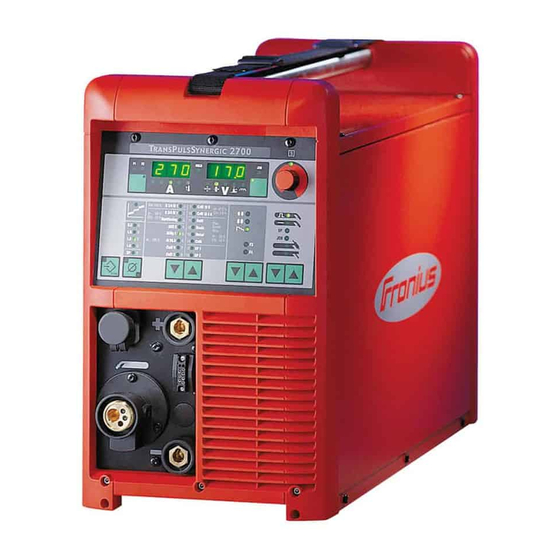
TransPuls Synergic 2700
TransPuls Synergic 3200/4000/5000
TIME 5000 Digital
CMT 4000 Advanced
42,0426,0001,EN 006-04092012
Welding Technology
/ Solar Electronics
Operating Instructions
Spare parts list
MIG/MAG Power source
Related Manuals for Fronius TransSynergic 5000
Summary of Contents for Fronius TransSynergic 5000
-
Page 1
/ Battery Charging Systems / Welding Technology / Solar Electronics Operating Instructions TransSynergic 4000/5000 Spare parts list TransPuls Synergic 2700 MIG/MAG Power source TransPuls Synergic 3200/4000/5000 TIME 5000 Digital CMT 4000 Advanced 42,0426,0001,EN 006-04092012… -
Page 3
Thank you for the trust you have placed in our company and congratulations on buying this high-quality Fronius product. These instructions will help you familiarise yourself with the product. Reading the instructions carefully will enable you to learn about the many different features it has to offer. -
Page 5: Table Of Contents
Contents Safety rules …………………………Explanation of safety symbols ………………….General …………………………Intended purpose ……………………..Environmental conditions……………………Obligations of the operator……………………Obligations of personnel ……………………Mains connection ……………………..Protecting yourself and others ………………….Noise emission values …………………….. Danger from toxic gases and vapours ………………..Danger from flying sparks ……………………
-
Page 6
Displaying the software version ………………….Comfort / CrNi / Steel control panel ………………….Difference between Comfort, CrNi and Steel control panels …………..Comfort control panel……………………..Key combinations — special functions………………..Displaying the feeder inching speed ………………… Displaying the gas pre-flow and gas post-flow time…………….Displaying the software version …………………. -
Page 7
Safety…………………………Connecting the mains cable……………………Replacing the strain-relief device………………….Start-up …………………………Safety…………………………Remarks on the cooling unit ……………………. Information on system components …………………. Overview …………………………. Commissioning the TPS 2700 ……………………General …………………………Recommendation for water-cooled applications ………………. Connecting the gas cylinder……………………Establishing a ground (earth) connection ………………… -
Page 8
Corrections during welding ……………………104 Adjusting parameters for correction …………………. 106 Special functions and options ……………………107 Arc break watchdog function……………………. 107 Ignition time-out function……………………107 Spatter-free ignition option……………………107 SynchroPulse option ……………………..108 Robot welding ……………………….110 Prerequisite……………………….110 General ………………………… -
Page 9
Process setup menu for the Comfort, US, TIME 5000 Digital and CMT control panels ……. 138 Parameters for MIG/MAG welding in the Process setup menu …………138 Parameters for TIG welding in the Process setup menu …………..141 Parameters for MMA welding in the Process setup menu …………..141 Mode setup menu ………………………. -
Page 10
Technical data — US devices ……………………. 189 Technical data — Alu edition, CrNi edition, Yard edition and CMT variants ……….. 189 TIME 5000 Digital ……………………..189 CMT 4000 Advanced ……………………..190 CMT 4000 Advanced MV……………………191 Welding program databases ……………………193 Explanation of symbols ……………………. -
Page 11: Safety Rules
Safety rules Explanation of DANGER! indicates immediate and real danger. If it is not avoided, death or se- safety symbols rious injury will result. WARNING! indicates a potentially dangerous situation. Death or serious injury may result if appropriate precautions are not taken. CAUTION! indicates a situation where damage or injury could occur.
-
Page 12: Intended Purpose
Intended purpose The device is to be used exclusively for its intended purpose. The device is intended for the welding process described on the rating plate only. Any use above and beyond this purpose is deemed improper. The manufac- turer shall not be liable for any damage resulting from such improper use. Utilisation in accordance with the «intended purpose»…
-
Page 13: Obligations Of Personnel
Obligations of Before using the device, all persons instructed to do so undertake: personnel to observe the basic instructions regarding safety at work and accident prevention to read these operating instructions, especially the «Safety rules» section and sign to confirm that they have understood them and will follow them. Before leaving the work area, ensure that people or property cannot come to any harm in your absence.
-
Page 14: Noise Emission Values
protect eyes and face from UV rays, heat and sparks using a protective visor and regulation filter. wear regulation protective goggles with side protection behind the safety visor. wear stout footwear that provides insulation even in wet conditions. protect the hands with suitable gloves (electrically insulated and providing protection against heat).
-
Page 15: Danger From Flying Sparks
If there is any doubt about whether the extraction system is powerful enough, then the measured toxic emission values should be compared with the permis- sible limit values. The following components are responsible, amongst other things, for the de- gree of toxicity of welding fumes: Metals used for the workpiece Electrodes Coatings…
-
Page 16
All cables and leads must be complete, undamaged, insulated and adequately dimensioned. Loose connections, scorched, damaged or inadequately dimen- sioned cables and leads must be repaired/replaced immediately. Do not sling cables or leads around either the body or parts of the body. The electrode (rod electrode, tungsten electrode, welding wire, etc) must never be immersed in liquid for cooling never be touched when current is flowing. -
Page 17: Meandering Welding Currents
Meandering weld- If the following instructions are ignored, meandering welding currents can de- ing currents velop with the following consequences: Fire hazard Overheating of parts connected to the workpiece Irreparable damage to PE conductors Damage to device and other electrical equipment Ensure that the workpiece is held securely by the workpiece clamp.
-
Page 18: Emf Measures
Check for possible problems, and check and evaluate neighbouring devices’ resistance to interference according to national and international require- ments: Safety features power, signal and data transfer lines IT and telecommunications devices measuring and calibrating devices Supporting measures for avoidance of EMC problems: Mains supply if electromagnetic interference arises despite correct mains connec- tion, additional measures are necessary (e.g.
-
Page 19
The welding wire emerging from the welding torch poses a high risk of injury (piercing of the hand, injuries to the face and eyes, etc.). Always keep the welding torch away from the body (devices with wire-feed unit) and wear suitable protective goggles. Never touch the workpiece during or after welding — risk of burns. -
Page 20: Danger From Shielding Gas Cylinders
Danger from Shielding gas cylinders contain gas under pressure and can explode if dam- shielding gas cyl- aged. As the shielding gas cylinders are part of the welding equipment, they inders must be handled with the greatest of care. Protect shielding gas cylinders containing compressed gas from excessive heat, mechanical impact, slag, naked flames, sparks and arcs.
-
Page 21: Safety Measures In Normal Operation
When transporting the device, observe the relevant national and local guide- lines and accident prevention regulations. This applies especially to guidelines regarding the risks arising during transportation. Before transporting the device, allow coolant to drain completely and detach the following components: Wire-feed unit Wirespool Shielding gas cylinder…
-
Page 22: Maintenance And Repair
Maintenance and It is impossible to guarantee that bought-in parts are designed and manufac- repair tured to meet the demands made on them, or that they satisfy safety require- ments. Use only original replacement and wearing parts (also applies to standard parts).
-
Page 23: Data Protection
Data protection The user is responsible for the safekeeping of any changes made to the fac- tory settings. The manufacturer accepts no liability for any deleted personal settings. Copyright Copyright of these operating instructions remains with the manufacturer. The text and illustrations are all technically correct at the time of printing. We reserve the right to make changes.
-
Page 25: General Information
General information…
-
Page 27: General
General Device concept The TransSynergic (TS) 4000 and TS 5000 and TransPulsSynergic (TPS) 2700, TPS 3200, TPS 4000 and TPS 5000 power sour- ces are fully digitised microprocessor-con- trolled inverter power sources. The modular design and potential for sys- tem add-ons ensure a high degree of flexi- bility.
-
Page 28
Nur vorhanden bei Stromquelle „TPS 2700“ und auf Drahtvorschüben… -
Page 29: Special Versions
Special versions General Professional processing of specific materials requires welding programs that are specially matched to the different materials in question. The special versions of the digital power sources are perfectly matched to these requirements. As a result the most important weld- ing programs can be called up directly from the operating panel.
-
Page 30: Time 5000 Digital
ised pulse cycles. Special features are targeted heat input, a higher deposition rate, better gap bridging properties, precise droplet detachment and an extremely stable arc. CMT Advanced is suitable for: joining thin sheets with outstanding gap bridging properties High-strength steels with low heat input Spots: precisely defined drop volumes and defined heat input Root passes with no pool support Brazing high-strength and ultra high-strength steels…
-
Page 31: System Components
System components General Digital power sources can be run with various system components and options. This makes it possible to optimise procedures and to simplify machine handling and operation, as necessitated by the particular field of application in which the power source is to be used.
-
Page 33: Control Elements And Connections
Control elements and connections…
-
Page 35: Description Of The Control Panels
Description of the control panels General The functions on the control panels are all arranged in a logical way. The various welding parameters can easily be selected using buttons and can just as easily be altered using buttons or the adjusting dial displayed on the digital display during welding The synergic function ensures that all other welding parameters are adjusted when an in- dividual parameter has been changed.
-
Page 36: Standard Control Panel
Standard control panel General NOTE! On the Standard control panel, only the MIG/MAG standard synergic welding process is available. The following processes and functions are not avail- able and cannot be retrofitted: MIG/MAG pulse synergic welding Job mode TIG welding Manual metal arc welding Spot welding Any changes to the “Welding current”…
-
Page 37
Function Parameter selection button for selecting the following parameters: Sheet thickness Sheet thickness in mm or in. Welding current Welding current in A Before the start of welding, the machine automatically displays a stand- ard value based on the programmed parameters. During welding, the actual value is displayed. -
Page 38: Key Combinations — Special Functions
Function (14) Intermediate arc indicator a spatter-prone intermediate arc occurs between the short arc and the spray arc. The intermediate arc indicator lights up to alert you to this critical area (15) Store button for opening the Setup menu (16) Gas test button for setting the required gas flow rate on the pressure regulator.
-
Page 39
Press the Material button (12) again to display the number of the wire-feed unit (A or B in the case of twin-head mounts) and the soft- ware version of the wire-feed unit (e.g.: A 1.5 | 0.23). Press the Material button (12) a third time to display the actual arc burning time since starting for the first time (e.g. -
Page 40: Comfort / Crni / Steel Control Panel
Comfort / CrNi / Steel control panel Difference be- The Comfort, CrNi and Steel control panels are identical except for the type of material tween Comfort, used in their construction. The following section deals specifically with the Comfort control CrNi and Steel panel, but all the functions described apply equally to the CrNi and Steel control panels.
-
Page 41
Function NOTE! The functions available on the control panel of system compo- nents are restricted in the same way as those on the control panel of the power source. Parameter selection button for selecting the following parameters: a-dimension Dependent on the set welding speed Sheet thickness Sheet thickness in mm or in. -
Page 42
Function (14) Droplet detachment correction/arc force dynamic correction/arc force dy- namic LED lights up when the droplet detachment correction/arc force dynamic correction/ arc force dynamic parameter is selected (15) Welding voltage LED lights up when the welding voltage parameter is selected (16) Welding speed LED lights up when the welding speed parameter is selected… -
Page 43: Key Combinations — Special Functions
Function (22) Process button(s) for selecting the welding process MIG/MAG pulse synergic welding MIG/MAG standard synergic welding MIG/MAG standard manual welding Job mode TIG welding with touchdown ignition Manual metal arc welding When a process is selected, the LED on the relevant symbol lights up. (23) Mode button for selecting the mode…
-
Page 44: Displaying The Gas Pre-Flow And Gas Post-Flow Time
Use the adjusting dial to change the feeder inching speed Press the Store button to exit. Displaying the gas pre-flow and The set gas pre-flow time is displayed (e.g. GPr | 0.1 s) gas post-flow time Use the adjusting dial to change the gas pre-flow time Then press the Process button (22) to display the gas post-flow time setting (e.g.
-
Page 45: Us Control Panel
US control panel US control panel (10) (12) (14) (16) (18) (11) (13) (15) (17) (19) (25) (23) (21) (26) (24) (22) (20) Function Inch Forward (feeder inching) button for feeding the wire electrode into the torch-hosepack with no accompanying flow of gas or current For information on the various wire feed sequences that are possible when the welder presses and holds the «Feeder inching»…
-
Page 46
Function Parameter selection button for selecting the following parameters: Sheet thickness Sheet thickness in mm or in. Welding current Welding current in A Before the start of welding, the machine automatically displays a stand- ard value based on the programmed parameters. During welding, the actual value is displayed. -
Page 47
Function (17) F3 indicator LED lights up when the F3 indicator parameter is selected (18) Parameter selection button for selecting the following parameters: Arc length correction for correcting the arc length Droplet detachment correction/arc force dynamic correction/arc force dynamic has a different function assigned to it, depending on the process being used. -
Page 48: Key Combinations — Special Functions
Function (22) Material button for selecting the filler metal and shielding gas to be used. Parameters SP1 and SP2 are reserved for additional materials. When a material is selected, the LED behind the relevant filler metal lights up. (23) Diameter / Index (wire diameter) button for selecting the diameter of the wire to be used.
-
Page 49: Displaying The Software Version
Displaying the In addition to the software version, these special functions can also be used to display the software version version number of the welding database, the wire-feed unit number, the software version of the wire-feed unit and the arc burning time. The software version is displayed Press the Material button (22) to display the version number of the welding database…
-
Page 50: Time 5000 Digital Control Panel
TIME 5000 Digital control panel TIME 5000 Digital control panel (10) (12) (14) (16) (18) (20) (11) (13) (15) (17) (19) (21) (27) (25) (23) (28) (26) (24) (22) Function Inch Forward (feeder inching) button for feeding the wire electrode into the torch-hosepack with no accompanying flow of gas or current For information on the various wire feed sequences that are possible when the welder presses and holds the «Feeder inching»…
-
Page 51
Function Parameter selection button for selecting the following parameters: a-dimension depending on the set welding speed Sheet thickness Sheet thickness in mm or in. Welding current Welding current in A Before the start of welding, the machine automatically displays a stand- ard value based on the programmed parameters. -
Page 52
Function (15) Welding voltage LED lights up when the welding voltage parameter is selected (16) Welding speed LED lights up when the welding speed parameter is selected (17) Right digital display (18) Job no. LED lights up when the job number parameter is selected (19) F3 indicator LED lights up when the F3 indicator parameter is selected… -
Page 53: Key Combinations — Special Functions
Function (23) Mode button for selecting the mode 2-step mode 4-step mode Special 4-step mode (aluminium welding start-up) Spot welding mode Operating mode When a mode is selected, the LED behind the relevant symbol lights up. (24) Material button for selecting the filler metal and shielding gas to be used. Parameters SP1 and SP2 are reserved for additional materials.
-
Page 54: Displaying The Gas Pre-Flow And Gas Post-Flow Time
Displaying the gas pre-flow and The set gas pre-flow time is displayed (e.g. GPr | 0.1 s) gas post-flow time Use the adjusting dial to change the gas pre-flow time Then press the Process button (20) to display the gas post-flow time setting (e.g.
-
Page 55: Cmt Control Panel
CMT control panel CMT control pan- (10) (12) (14) (16) (18) (11) (13) (15) (17) (24) (22) (20) (25) (23) (21) (19) Function Inch Forward (feeder inching) button for feeding the wire electrode into the torch-hosepack with no accompanying flow of gas or current For information on the various wire feed sequences that are possible when the welder presses and holds the «Feeder inching»…
-
Page 56
Function Wire-feed unit drive current-input indicator indicates that the wire-feed unit drive is switched on If the indicators are lit up on the parameter selection button (3) and on the adjust- ing dial (19), then the indicated / selected parameter can be altered using the ad- justing dial (19). -
Page 57
Function (17) Parameter selection button for selecting the following parameters: Arc length correction for correcting the arc length Droplet detachment correction/arc force dynamic correction/arc force dynamic has a different function assigned to it, depending on the process being used. A description of the various functions can be found in the Welding chapter under the corresponding process. -
Page 58: Key Combinations — Special Functions
Function (22) Diameter / Index (wire diameter) button for selecting the diameter of the wire to be used. Parameter SP is reserved for additional wire diameters. When a wire diameter is selected, the LED behind the relevant wire diameter lights up. (23) CMT Pulse indicator lights up when a CMT/pulse characteristic is selected…
-
Page 59
The software version is displayed Press the Material button (24) to display the version number of the welding database (e.g.: 0 | 029 = M0029). Press the Material button (24) again to display the number of the wire-feed unit (A or B in the case of twin-head mounts) and the soft- ware version of the wire-feed unit (e.g.: A 1.5 | 0.23). -
Page 60: Yard Control Panel
Yard control panel Yard control pan- (10) (12) (14) (16) (18) (11) (13) (15) (17) (24) (22) (20) (25) (23) (21) (19) Function Inch Forward (feeder inching) button for feeding the wire electrode into the torch-hosepack with no accompanying flow of gas or current For information on the various wire feed sequences that are possible when the welder presses and holds the «Feeder inching»…
-
Page 61
Function Parameter selection button for selecting the following parameters: Sheet thickness Sheet thickness in mm or in. Welding current Welding current in A Before the start of welding, the machine automatically displays a stand- ard value based on the programmed parameters. During welding, the actual value is displayed. -
Page 62
Function (16) F3 indicator LED lights up when the F3 indicator parameter is selected (17) Parameter selection button for selecting the following parameters: Arc length correction for correcting the arc length Droplet detachment correction/arc force dynamic correction/arc force dynamic has a different function assigned to it, depending on the process being used. -
Page 63: Key Combinations — Special Functions
Function (21) Material button for selecting the filler metal and shielding gas to be used. Parameters SP1 and SP2 are reserved for additional materials. When a material is selected, the LED behind the relevant filler metal lights up. (22) Diameter / Index (wire diameter) button for selecting the diameter of the wire to be used.
-
Page 64: Displaying The Software Version
Displaying the In addition to the software version, these special functions can also be used to display the software version version number of the welding database, the wire-feed unit number, the software version of the wire-feed unit and the arc burning time. The software version is displayed Press the Material button (24) to display the version number of the welding database…
-
Page 65: Remote» Control Panel
“Remote” control panel General The Remote operating panel is fitted to the Remote power source. The Remote power source is designed for automated and robot applications and is controlled exclusively via the LocalNet. The Remote power source can be operated via the following system add-ons: Remote controls Robot interfaces Field bus systems…
-
Page 66: Cmt Remote Control Panel
CMT Remote control panel General The CMT Remote control panel is fitted to the CMT Remote power source and CMT Ad- vanced power source. The CMT Remote power source and CMT Advanced power source are designed for automated and robot applications and are controlled exclusively via the LocalNet.
-
Page 67: Connections, Switches And Mechanical Components
Connections, switches and mechanical components TPS 2700 power Front view Rear view Side view source (1) (2) (7) (8) Function LocalNet connection Standardised connection socket for system add-ons (e.g. remote control, Job- Master torch, etc.) (+) — Current socket with bayonet latch for: connecting the grounding (earthing) cable during TIG welding connecting the electrode cable or grounding (earthing) cable during MMA…
-
Page 68: Tps 2700 Cmt Power Source
TPS 2700 CMT Front view Rear view Side view power source (1) (2) (7) (8) (11) (10) (12) (13) Function LocalNet connection Standardised connection socket for system add-ons (e.g. remote control, Job- Master torch, etc.) Motor control connection for connecting the control line from the CMT drive unit Welding torch control connection for the welding torch control plug LHSB connection…
-
Page 69: Ts 4000 / 5000, Tps 3200 / 4000 / 5000, Time 5000 Digital Power Sources
TS 4000 / 5000, Front view Rear view TPS 3200 / 4000 / 5000, TIME 5000 Digital power sources Function (-) — Current socket with bayonet latch for: connecting the grounding (earthing) cable during MIG/MAG welding the current connection for the TIG welding torch connecting the electrode cable or grounding (earthing) cable during MMA welding (depending on the type of electrode used) Mains switch…
-
Page 70: Cmt 4000 Advanced Power Source
Function Second (-) — Current socket with bayonet latch (optional) for: connecting the interconnecting hosepack in MIG/MAG welding for polarity re- versal (e.g. for innershield and flux core wire welding) specially for automated and robot applications where the interconnecting hosepack and grounding (earthing) cable are to be connected to one side of the power source (e.g.
-
Page 71
Function Blanking cover Reserved for LocalNet connection Blanking cover Reserved for LocalNet connection LocalNet connection for interconnecting hosepack LHSB (LocalNet High-Speed Bus) connection Mains cable with strain relief device… -
Page 73: Installation And Commissioning
Installation and commissioning…
-
Page 75: Minimum Equipment Needed For Welding Task
Minimum equipment needed for welding task General Depending on which welding process you intend to use, a certain minimum equipment lev- el will be needed in order to work with the power source. The welding processes and the minimum equipment levels required for the welding task are then described.
-
Page 76: Cmt Automated Welding
CMT automated CMT power source: TPS 3200 / 4000 / 5000 (or CMT remote power source with RCU welding 5000i remote control) Robot interface or field bus connection Grounding (earthing) cable CMT welding torch incl. CMT drive unit Cooling unit CMT wire-feed unit CMT interconnecting hosepack CMT wire buffer…
-
Page 77: Before Installation And Commissioning
Before installation and commissioning Safety WARNING! Operating the equipment incorrectly can cause serious injury and damage. Do not use the functions described until you have thoroughly read and understood the following documents: these operating instructions all the operating instructions for the system components, especially the safe- ty rules Proper use The power source may only be used for MIG/MAG, MMA and TIG welding.
-
Page 78: Connecting Up The Mains Cable On Us Power Sources
Connecting up the mains cable on US power sourc- General The US power sources are supplied without a mains cable. A mains cable appropriate for the connection voltage must be fitted prior to commissioning. A strain-relief device for a cable cross-section AWG 10 is installed on the power source. Strain-relief devices for larger cable cross-sections must be designed accordingly.
-
Page 79: Replacing The Strain-Relief Device
Undo the screws (2 x) and clamping nut (size 30) on the strain-relief device Insert the mains cable into the strain- relief device NOTE! Push the mains cable in far enough to make it possible to connect the PE conductor and the phase conductors to the block ter- minal properly.
-
Page 80
Insert the hexagon nut (size 50 mm) into the holding plate NOTE! The points of the hexagon nut must point towards the holding plate for a reliable ground (earth) connection to the power source housing. Screw the front of the large strain-relief device into the hexagon nut (size 50 mm). -
Page 81: Start-Up
Start-up Safety WARNING! An electric shock can be fatal. If the power source is connected to the mains electricity supply during installation, there is a high risk of very serious in- jury and damage. Before carrying out any work on the device make sure that: the power source mains switch is in the «O»…
-
Page 82: Commissioning The Tps 2700
Commissioning the TPS 2700 General Commissioning the TPS 2700 power source is described by reference to a manual gas- cooled MIG/MAG application. Recommenda- Use the PickUp trolley tion for water- Fit the cooling unit to the PickUp trolley cooled applica- Fit the TPS 2700 power supply to the cooling unit tions Only use water-cooled welding torches with an external water connection…
-
Page 83: Establishing A Ground (Earth) Connection
Establishing a Plug the grounding (earthing) cable ground (earth) into the (-) current socket and twist to connection fasten it Use the other end of the grounding (earthing) cable to establish a connec- tion to the workpiece Connecting the grounding (earthing) cable to the TPS 2700 Connecting the Check that the torch is correctly and…
-
Page 84: Inserting The Wirespool
Inserting the wire- CAUTION! Risk of injury from springiness of spooled wire electrode. While insert- spool ing the wirespool, hold the end of the wire electrode firmly to avoid injuries caused by the wire springing back. CAUTION! Risk of injury from falling wirespool. Make sure the wirespool sits se- curely on the spool holder.
-
Page 85: Feeding In The Wire Electrode
Feeding in the CAUTION! Risk of injury from springiness of spooled wire electrode. When insert- wire electrode ing the wire electrode into the 4-roller drive, hold the end of the wire electrode firmly to avoid injuries caused by the wire springing back. CAUTION! Risk of damage to the welding torch from sharp end of wire electrode.
-
Page 86: Setting The Contact Pressure
CAUTION! Risk of injury from wire electrode emerging at speed. Keep the weld- ing torch away from face and body when pressing the feeder inching / inch for- ward button. Setting the con- NOTE! Set the contact pressure in tact pressure such a way that the wire electrode is not deformed but nevertheless ensures that the wire is transport-…
-
Page 87: Design Of The Brake
STOP STOP Design of the CAUTION! Risk of injury and damage from falling wirespool. To ensure that the brake wirespool is properly in place and that the brake works properly, fit the brake ac- cording to the following diagram. KLEBER, GLUE, COLLE…
-
Page 88: Commissioning The Ts 4000 / 5000, Tps 3200 / 4000 / 5000, Time 5000 Digital
Commissioning the TS 4000 / 5000, TPS 3200 / 4000 / 5000, TIME 5000 Digital General Commissioning the TS 4000 / 5000 and TPS 3200 / 4000 / 5000 power sources is de- scribed by reference to a manual water-cooled MIG/MAG application. Fitting the system The diagram below is intended to show you how to fit the individual system components.
-
Page 89: Fixing The Strain-Relief Device In Place
Fixing the strain- Introduce the pin on the power source relief device in strain-relief device for the interconnec- place ting-hosepack into the opening provi- ded in the base of the trolley. Use two screws supplied with the inter- connecting hosepack to fasten the strain-relief device to the base of the trolley.
-
Page 90: Connecting The Gas Cylinder
Plug the welding potential bayonet plug on the interconnecting hosepack into the (+) socket and twist to fasten it Plug the LocalNet plug on the interconnecting hosepack into the LocalNet connection and secure with a union nut CMT power sources only: Connect the LHSB plug to the LHSB connection Connect the water feed hose (blue) (3) to the cooling unit Connect the water return hose (red) (2) to the cooling unit…
-
Page 91: Establishing A Ground (Earth) Connection
Establishing a Plug the grounding (earthing) cable ground (earth) into the (-) current socket and twist to connection fasten it Use the other end of the grounding (earthing) cable to establish a connec- tion to the workpiece Connecting the Check that the torch is correctly and welding torch completely tooled up.
-
Page 92: Commissioning The Cmt4000 Advanced
Commissioning the CMT4000 Advanced Fitting the system The diagram below is intended to show you how to fit the individual system components. components For detailed information about the individual steps, please refer to the operating instruc- (overview) tions for the system components. WARNING! If gas cylinders topple over, there is a risk of very serious injury and damage.
-
Page 93: Preparing The Wire-Feed Unit
Establish a ground (earth) connection between the workpiece and power source Connect the gas cylinder Connect the RCU 5000i remote control Make the connection to the robot control Preparing the Carry out the following steps in accordance with the wire-feed unit operating instructions: wire-feed unit Insert the feed rollers in the wire-feed unit Insert the wirespool or basket-type spool with adapter in the wire-feed unit…
-
Page 95: Welding
Welding…
-
Page 97: Mig/Mag Modes
MIG/MAG modes General WARNING! Operating the equipment incorrectly can cause serious injury and damage. Do not use the functions described until you have thoroughly read and understood the following documents: these operating instructions all the operating instructions for the system components, especially the safe- ty rules See the Setup menu for information on settings, setting range and units of measurement for the available parameters.
-
Page 98: 2-Step Mode
2-step mode “2-step mode“ is suitable for Tacking work Short weld seams Automated and robot welding 4-step mode «4-step mode» is suitable for longer weld seams.
-
Page 99: Special 4-Step Mode
Special 4-step “Special 4-step mode ” is particularly suitable for welding aluminium materials. The spe- mode cial pattern of the welding current curve takes account of the high thermal conductivity of aluminium. Spot welding The “Spot welding” mode is suitable for welding joins on overlapped sheets. Procedure for spot welding: Hold welding torch in the vertical Press and release the torch trigger…
-
Page 100: Mig/Mag Welding
MIG/MAG welding Safety WARNING! Operating the equipment incorrectly can cause serious injury and damage. Do not use the functions described until you have thoroughly read and understood the following documents: these operating instructions all the operating instructions for the system components, especially the safe- ty rules WARNING! An electric shock can be fatal.
-
Page 101: Mig/Mag Synergic Welding
MIG/MAG synergic welding General The inputs required for MIG/MAG synergic welding (pulse/standard) are described by ref- erence to the Comfort control panel. MIG/MAG syner- Press the Process button to select the desired welding process: gic welding MIG/MAG pulse synergic welding MIG/MAG standard synergic welding Press the Material button to select the filler metal and shielding gas used The assignment of SP1 and SP2 depends on the welding database used for the power…
-
Page 102: Corrections During Welding
CAUTION! Risk of injury and damage from electric shock and from the wire electrode emerging from the torch. When pressing the torch trigger: keep the torch away from your face and body do not point the welding torch at people make sure that the wire electrode does not touch any electrically conducting or earthed (grounded) parts, such as the housing, etc.
-
Page 103: Mig/Mag Standard Manual Welding
MIG/MAG standard manual welding General The MIG/MAG standard manual welding process is a MIG/MAG welding process with no Synergic function. Changing one parameter does not result in any automatic adjustments to the other param- eters. All of the variable parameters must therefore be adjusted individually, as dictated by the welding process in question.
-
Page 104: Corrections During Welding
All welding parameter set values that have been set using the adjusting dial or buttons on the welding torch remain stored until the next time they are changed. This is true even if the power source is switched off and on again in the meantime To display the actual welding current during welding: press the Parameter selection button and select the welding current parameter the actual welding current is displayed on the digital display during welding…
-
Page 105: Cmt Welding
CMT welding General The inputs required for CMT welding are described by reference to the CMT control panel. Settings for CMT applications with the CMT remote power source and the RCU 5000i re- mote control can be found in the operating instructions for the RCU 5000i remote control. CMT welding Press the Process button to select the CMT/CMT pulse process: Press the Material button to select the filler metal and shielding gas used…
-
Page 106: Corrections During Welding
Use the adjusting dial to set the selected parameter to the desired value. The param- eter value is displayed in the digital display located above it. The sheet thickness, welding current, wire feed speed and welding voltage parame- ters are directly interlinked. It is only necessary to alter one of the parameters, as the other parameters are immediately adjusted to match.
-
Page 107
+5 soft, low-spatter arc The arc force dynamic can be corrected with the following filler metals: G3Si 1 / Ar + 18 % CO2 / 1.0 mm G3Si 1 / Ar + 18 % CO2 / 1.2 mm HotStart pulse cycles for setting the HotStart pulse cycles 0 pulses +5 100 pulses… -
Page 108: Adjusting Parameters For Correction
Adjusting param- Press the Parameter selection button to select the parameter you wish to correct eters for correc- Use the adjusting dial to set the selected parameter to the desired value. The param- tion eter value is displayed in the digital display located above it.
-
Page 109: Special Functions And Options
Once the correct arc length has been reached, the wire starts being fed at the speed specified for this welding process. NOTE! The optimum function of the spatter-free ignition option can only be guar- anteed in aluminium applications in conjunction with Fronius push-pull wire-feed unit systems. System requirements: Firmware version on the power source: OFFICIAL UST V2.60.1…
-
Page 110: Synchropulse Option
Firmware version on the wire-feed unit: OFFICIAL SR 1 V1.40.15 NOTE! External enabling of the SynchroPulse option is possible from firmware version OFFICIAL UST V2.70.1 (power source) upwards. Only Fronius push-pull wire-feed unit systems are supported. NOTE! As long as the Standard manual welding process is selected, the Syn-…
-
Page 111
Function of SynchroPulse in «Special 4-step» mode I-S = Starting current phase SL = Slope I-E = End-crater phase v = Wire feed speed Al.2 SynchroPulse function… -
Page 112: Robot Welding
Robot welding Prerequisite A robot interface or field bus system is needed in order to be able to control the power source from a robot control unit. General 2-step mode is selected automatically if a ROB 4000 / 5000 robot interface or field bus sys- tem is connected.
-
Page 113: Wire-Stick Control Function
Wire-stick control The wire-stick control function is available if a robot interface or field bus system is con- function nected to the LocalNet. After the end of welding, the wire-stick control function detects any “sticking” of the wire electrode in the solidifying weld pool. If a sticking wire electrode is detected within 750 ms after the end of welding, the error message “Err | 054”…
-
Page 114: Tig Welding
TIG welding Safety WARNING! Operating the equipment incorrectly can cause serious injury and damage. Do not use the functions described until you have thoroughly read and understood the following documents: these operating instructions all the operating instructions for the system components, especially the safe- ty rules WARNING! An electric shock can be fatal.
-
Page 115: Igniting The Arc
NOTE! Parameters that have been set on a system component control panel (e.g. wire feed unit or remote control) might not be able to be changed on the power source control panel. Press the Parameter selection button. The LED indicator on the button must light up. Use the adjusting dial to set the desired amperage.
-
Page 116: Finishing Welding
Raise the torch and pivot it into the nor- mal position — the arc ignites Carry out welding Arc ignited — welding commences Finishing welding NOTE! When the welding action is finished, the gas post-flow time required to protect the tungsten electrode and the weld seam depends on the welding cur- rent.
-
Page 117
Welding Welding At the end of the welding action, briefly raise the torch The arc length is increased significant- Raising the torch Lower the welding torch The arc length is reduced signifi- cantly The optional TIG Comfort Stop function is triggered Lowering the torch… -
Page 118: Tig Welding With Tig Comfort Stop
Keep the torch in the same position The welding current is continuous- ly decreased (downslope) The arc goes out NOTE! The downslope is preset and cannot be adjusted. Raise the torch from the workpiece. Keeping the torch at the same height and then remo- ving it TIG welding with Welding current curve with the TIG Comfort Stop option activated:…
-
Page 119: Mma Welding
MMA welding Safety WARNING! Operating the equipment incorrectly can cause serious injury and damage. Do not use the functions described until you have thoroughly read and understood the following documents: these operating instructions all the operating instructions for the system components, especially the safe- ty rules WARNING! An electric shock can be fatal.
-
Page 120: Corrections During Welding
NOTE! Parameters that have been set on a system component control panel (e.g. wire feed unit or remote control) might not be able to be changed on the power source control panel. Press the Parameter selection button. The LED indicator on the button must light up. Use the adjusting dial to set the desired amperage.
-
Page 121: Softstart Function
Legend Hti ..Hot-current time, 0 — 2 s, factory set- I (A) ting: 0.5 s HCU … Hot-start current, 0 — 200%, factory HCU > I setting 150 % ..Main current = set welding current Function: during the specified hot-current time (Hti), the welding current is increased to a certain value.
-
Page 122: Job Mode
Job mode General Job mode enhances the quality of welding engineering fabrication, both in manual and au- tomated welding. Up to 100 common jobs (operating points) can be reproduced in job mode, avoiding the need to document parameters by hand. Prerequisites Job mode is only available on power sources with the following control panels: Comfort control panel…
-
Page 123: Retrieving A Job
Briefly press the Store button to change to the job menu The first vacant program location for the job is indicated. Select the desired program location with the adjusting dial, or else leave the suggest- ed program location unchanged Press and hold the Store button NOTE! If the selected program location already has a job stored in it, then this existing job will be overwritten with the new job.
-
Page 124: Copying/Overwriting A Job
MIG/MAG jobs can also be selected via the JobMaster or Up/Down welding torches. When you retrieve a job directly from the power source, you can also select vacant program locations (symbolised by “- — -”). Only pre-programmed program locations can be selected via the JobMaster or Up/Down torches, however.
-
Page 125: Deleting A Job
Release the Store button. Briefly press the Store button to exit from the Job menu The power source switches to the setting selected before the job was copied. Deleting a job NOTE! Jobs are deleted in the Job menu, not in the job mode process. Stored jobs can also be deleted again.
-
Page 127: Setup Settings
Setup settings…
-
Page 129: Job Correction
Job correction General In the Job correction menu, setup parame- ters can be adapted to the specific require- ments of individual jobs. Job correction menu: Overview Opening the Job Press and hold the Store button correction menu Press the parameter selection button (left) Release the Store button The power source is now in the Job correction menu.
-
Page 130: Parameters In The Job Correction Menu
Parameters in the There are two types of parameter in the job correction menu: job correction menu permanently settable parameters: cannot be altered apart from in the job correction menu. can only be corrected in the job correction menu. parameters that can be corrected at a later time: with boundary values for which an adjusting range can be defined within this adjusting range, these parameters can be corrected from the following con- trol elements:…
-
Page 131
Unit Setting range 0 — 9.9 Factory setting Gas post-flow time Unit Setting range 0 — 9.9 Factory setting Feeder creep — wire feeder creep speed Unit m/min Setting range AUT, OFF or 0.5 — max. AUT, OFF or 19.69 — max. Additional possible setting with SFi option: SFi Factory setting NOTE! If Fdc is set to AUT, the value from the welding program database will be… -
Page 132: Parameters That Can Be Corrected At A Later Time
Factory setting time — End current — Final current duration Unit Setting range OFF or 0.1 — 9.9 Factory setting Spot welding time Unit Setting range 0.1 — 5.0 Factory setting Frequency — for SynchroPulse option Unit Setting range OFF or 0.5 — 5 Factory setting delta Feeder — Welding power offset for the SynchroPulse option (defined by the wire feed speed)
-
Page 133
As long as the power source is switched on, the corrected parameter values remain saved. After the power source has been switched on again, the parameters are reset to the per- manently settable values. «Minimum» and «maximum» are used for setting ranges that differ according to power source, wire-feed unit, welding program, etc. -
Page 134
Job 2 Job 1 JSL = OFF Job 1 JSL = 0,1 — 9,9 s Job 2 Job 1 t (s) Job Slope The value that has been set for Job Slope is stored along with the Job currently selected. -
Page 135: Shielding Gas Setup Menu
Shielding gas setup menu General The Protective gas shield setup menu provides easy access to the protective gas shield settings. Protective gas Opening the Protective gas shield setup menu shield setup menu for the Press and hold the Store button standard control Press the Gas test button panel…
-
Page 136
Gas pre-flow time Unit Setting range 0 — 9.9 Factory setting Gas post-flow time Unit Setting range 0 — 9.9 Factory setting Gas purger Unit Setting range OFF or 0.1 — 10.0 Factory setting Purging of the shielding gas begins as soon as GPU is allocated a value. For safety reasons, purging of the shielding gas cannot be restarted until a new GPU value is entered. -
Page 137: Setup Menu For The Standard Control Panel
Setup menu for the standard control panel General The Setup menu provides easy access to expert knowledge in the power source and to additional functions. The Setup menu can be used to make simple adjustments of the weld- ing parameters to suit the various job settings. Setup menu for Opening the Protective gas shield setup menu the standard con-…
-
Page 138
NOTE! If Fdc is set to AUT, the value from the welding program database will be used. If Fdc values are set manually and these values are faster than the wire feed speed that was set for the welding operation then the feeder creep speed is equal to the wire feed speed set for the welding operation. -
Page 139
I (current) — Starting current Unit % (of starting current) Setting range 0 — 200 Factory setting Slope Unit Setting range 0.1 — 9.9 Factory setting I (current) — End — Final current Unit % (of starting current) Setting range 0 — 200 Factory setting Reset power source to factory setting… -
Page 140: Process Setup Menu
Process setup menu General The Process setup menu provides simple access to expert knowledge in the power source and to additional functions. The Process setup menu can be used to make simple adjust- ments of the parameters to the various job settings. The Process setup menu can be accessed using the Comfort, US, TIME 5000 Digital and CMT control panels.
-
Page 141
Gas post-flow time Unit Setting range 0 — 9.9 Factory setting Feeder creep — Wire feeder creep speed used with the SFi option Unit m/min Setting range AUT, OFF or 0.5 — max. AUT, OFF or 19.69 — max. Factory setting NOTE! If Fdc is set to AUT, the value from the welding program database will be used. -
Page 142
Frequency — for SynchroPulse option Unit Setting range OFF or 0.5 — 5 Factory setting NOTE! In order to activate SynchroPulse, you must (as a minimum) change the value of the parameter F (frequency) from OFF to a value of between 0.5 Hz and 5 Hz. -
Page 143: Parameters For Tig Welding In The Process Setup Menu
NOTE! When the power source is reset, all the customised settings in the Setup menu are lost. When the power source is reset, jobs are not deleted but are retained in the memory. The functions in the second level of the Setup menu (2nd) are also not deleted. Exception: Ig- nition time-out welding parameter (ito).
-
Page 144: Mode Setup Menu
Mode setup menu General The Mode setup menu provides simple access to expert knowledge in the power source and to additional functions. The Mode setup menu can be used to make simple adjust- ments of the parameters to the various job settings. The Process setup menu can be accessed using the Comfort, US, TIME 5000 Digital and CMT control panels.
-
Page 145: Welding Parameters For «Special 4-Step Mode» In The Mode Setup Menu
I (current) — End — Final current Unit % (of starting current) Setting range 0 — 200 Factory setting time — Starting current — Starting current duration Unit Setting range OFF or 0.1 — 9.9 Factory setting time — End current — Final current duration Unit Setting range OFF or 0.1 — 9.9…
-
Page 146: Setup Menu — Level 2
Setup menu — Level 2 General The following functions are located in a second menu level: PPU (push-pull unit) r (welding circuit resistance measure- C-C (cooling unit cut-out) ment) Stc (wire-stick — only where there is a L (welding circuit inductivity display) robot interface) Eln (characteristic selection — not on Ito (ignition time-out)
-
Page 147: Setup Menu Level 2 For The Comfort, Us, Time 5000 Digital And Cmt Control Panels
Setup menu level Changing to the second menu level 2 for the Comfort, (2nd) US, TIME 5000 Open the Process setup menu Digital and CMT Select «2nd» welding parameter control panels Press and hold the Store button Press the Process button Release the Store button The power source is now in the second menu level (2nd) of the Setup menu.
-
Page 148
NOTE! Parameter C-C can be set differently for MIG/MAG welding and TIG weld- ing. Example: MIG/MAG welding process… e.g. use of a water-cooled welding torch: C-C = AUT TIG welding process… e.g. use of a gas-cooled welding torch: C-C = OFF Cooling time –… -
Page 149
OFF: The power source halts wire feed when the wire end sensor is triggered. «Err|056“ appears on the display. The power sources halts wire feed after completion of the current weld seam when the wire-end sensor is triggered. «Err|056» appears on the display. Acknowledge Err | 056 Insert a new wirespool and feed the wire electrode into the hosepack noE:… -
Page 150: Parameters For Operating Power Sources In Parallel In The Setup Menu Level2
NOTE! Please refer to «Digital gas control» operating instructions for more de- tailed explanations of the «COr» parameter. Real Energy Input – electrical energy of the arc relative to the welding speed Unit Setting range ON/OFF Factory setting Since the full range of values (1 kJ — 99999 kJ) cannot be displayed on the three-digit dis- play, the following display format has been selected: Value in kJ Indicator on display…
-
Page 151
AUT: The cooling unit cuts out after a 2-minute welding off-time NOTE! If the “FK 4000 thermostat” option has been installed in the cooling unit, the cooling unit cuts out as soon as the return temperature has dropped below 50°C, but no sooner than after a 2-minute welding off-time. ON: The cooling unit is permanently ON OFF: The cooling unit is permanently OFF If an FK 9000 cooling unit is used, the only possible settings are ON and OFF. -
Page 152: Parameters For Rod Electrode (Mma) Welding In The Setup Menu Level 2
Parameters for rod electrode Electrode line — characteristic selection (MMA) welding in Unit the Setup menu level 2 Setting range CON or 0.1 — 20 or P Factory setting Load line for rod electrode Load line for rod electrode where arc length is in- con — 20 A / V U (V) creased…
-
Page 153
Load line for rod electrode Load line for rod electrode where arc length is in- creased U (V) Load line for rod electrode where arc length is re- duced Characteristic where «CON» parameter is select- ed (constant welding current) Characteristic where «0.1 -20» parameter is se- lected (falling characteristic with adjustable slope) Characteristic where «P»… -
Page 154: Notes On The Use Of The Fac Parameter
U (Voltage) cut-off — Welding voltage limitation: Unit Setting range OFF or 5 — 95 Factory setting NOTE! The arc length depends on the welding voltage. To end the welding proc- ess, it is usually necessary to significantly lift the rod electrode away from the workpiece.
-
Page 155: Calibrating Push-Pull Unit
Calibrating push-pull unit General The push-pull unit must be calibrated before it is started up for the first time and whenever the wirefeed software is updated. If the push-pull unit is not calibrated, standard parame- ters will be used — which may lead to an unsatisfactory welding result. Calibrating the Access Setup menu: Level 1 push-pull unit -…
-
Page 156
SR41 SR43 Fronius unreeling device «VR 1530-22“ 22 m/min / 865 ipm Fronius unreeling device “VR 1530-30” 30 m/min / 1180 ipm (val- ue displayed on the digital display: 1.18) Fronius robot push-pull «KD Drive“ 10 m/min / 393.70 ipm Fronius robot push-pull “Robacta Drive”… -
Page 157
1) 2) 3) 54 Binzel robot push-pull “Master Feeder BG II” 55 Fronius “VR 1530 PD” unreeling device (d = 1.0 mm / 0.040 in.; material: steel) 56 Fronius “VR 1530 PD” unreeling device (d = 1.2 mm / 0.045 in.;… -
Page 158
CAUTION! Risk of injury from rotating cogs and drive parts. Keep hands away from rotating cogs and the wire drive. Press the “Feeder inching” button or the torch trigger The wire-feed unit motors are calibrated while not under load. During the calibration process «run»… -
Page 159: Service Codes For Push-Pull Calibration
Service codes for push-pull calibration Safety WARNING! An electric shock can be fatal. Before opening the device Turn the mains switch to the «O» position Unplug the machine from the mains Prevent it from being switched on again Using a suitable measuring instrument, check to make sure that electrically charged components (e.g.
-
Page 160: Service Codes When The Drive Units Are Engaged («Engaged» Calibration)
Service codes St1 | E 16 when the drive Cause: Push-pull calibration was interrupted: Quick-stop was activated by pressing units are engaged the torch trigger. («engaged» cali- Remedy: Repeat push-pull calibration bration) St2 | E 7 Cause: «Push-pull calibration — open-circuit» has not been carried out Remedy: Carry out «push-pull calibration — open-circuit»…
-
Page 161
St2 | E 14 Cause: At maximum wire feed speed, the motor current of the wire-feed unit motor is outside the permitted range. Possible reasons are disengaged wire-feed unit motors or wire feed problems. Remedy: Engage the drive units of both wire-feed unit motors, arrange the hosepack in as straight a line as possible;… -
Page 162: Measuring Welding Circuit Resistance R
Measuring welding circuit resistance r General Measuring the welding circuit resistance “r” makes it possible to have a constant welding result at all times, even with hosepacks of different lengths. The welding voltage at the arc is then always precisely regulated, regardless of the length and cross-sectional area of the hosepack.
-
Page 163
Fit the gas nozzle back onto the welding torch… -
Page 164: Displaying Welding Circuit Inductivity L
Displaying welding circuit inductivity L General The way that the interconnecting hosepack is arranged has a very significant effect on the weld properties. In MIG/MAG pulse synergic welding in particular, high welding circuit in- ductivity may occur, depending on the length of the interconnecting hosepack and the way it is arranged.
-
Page 165: Troubleshooting And Maintenance
Troubleshooting and maintenance…
-
Page 167: Troubleshooting
Troubleshooting General The digital power sources are equipped with an intelligent safety system. This means that apart from the fuse for the coolant pump, it has been possible to dispense with melting-type fuses entirely. After a possible malfunction or error has been remedied, the power source can be put back into normal operation again without any fuses having to be replaced.
-
Page 168
dSP | Exx Cause: Fault in the central control and regulation unit Remedy: Contact After-Sales Service dSP | Sy Cause: Fault in the central control and regulation unit Remedy: Contact After-Sales Service dSP | nSy Cause: Fault in the central control and regulation unit Remedy: Contact After-Sales Service E-S | toP… -
Page 169
EFd | 12.1 Cause: No actual rotational speed value from the wire-feed unit motor Remedy: Check the actual-value pick-up and the cable connections to and from it, and replace if necessary EFd | 12.2 Cause: No actual value rotational speed from the push-pull unit motor Remedy: Check the actual-value pick-up and the cable connections to and from it, and replace if necessary… -
Page 170
EFd | 30.1 Cause: LHSB connection to power source missing Remedy: Check LHSB connection to power source EFd | 30.3 Cause: LHSB connection to CMT drive unit missing Remedy: Check LHSB connection to CMT drive unit EFd | 31.1 Cause: Rotor calibration on the CMT drive unit failed Remedy: Switch power source off and on again;… -
Page 171
Err | 056 Cause: The «Wire-end check» option has detected the end of the wire electrode Remedy: Insert a new wirespool and feed the wire electrode into the hosepack; acknowledge Err | 056 by pressing the Store button Cause: Additional fan filter of the VR 1500 — 11 / 12 / 30 is contaminated air supply for the additional fan is no longer sufficient to cool the power elec- tronics the power electronics temperature switch has tripped… -
Page 172
Err |77.X The current limit set for a wire-feed unit motor has been exceeded Cause: Err 77.7 … Wire-feed unit motor current exceeded Err 77.8 … PPU motor current exceeded Remedy: Check the wire-feed unit components (e.g. feed rollers, inner liner, inlet/outlet nozzles, etc.);… -
Page 173
no | IGn Cause: Ignition time-out function is active: No current started flowing before the length of wire specified in the Setup menu had been fed. The safety cut-out of the power source has been triggered. Remedy: Shorten the wire stick-out; press the torch trigger repeatedly; clean the sur- face of the workpiece;… -
Page 174
tP1 | xxx Note: xxx is a temperature value Cause: Overtemperature in the primary circuit of the power source Remedy: Allow power source to cool down tP2 | xxx Note: xxx is a temperature value Cause: Overtemperature in the primary circuit of the power source Remedy: Allow power source to cool down tP3 | xxx… -
Page 175: Power Source — Troubleshooting
Power source — tSt | xxx troubleshooting Note: xxx is a temperature value Cause: Overtemperature in the control circuit Remedy: Allow power source to cool down Power source has no function Mains switch is on, but indicators are not lit up Cause: There is a break in the mains lead;…
-
Page 176
Nothing happens when the torch trigger is pressed Mains switch is on and indicators are lit up Cause: The control plug is not plugged in Remedy: Plug in the control plug Cause: Welding torch or welding torch control line is faulty Remedy: Change the welding torch Cause:… -
Page 177
Poor-quality weld properties Cause: Incorrect welding parameters Remedy: Check settings Cause: Poor grounding connection Remedy: Establish good contact with workpiece Cause: Too little or no shielding gas Remedy: Check pressure regulator, gas hose, gas solenoid valve, welding torch gas connection, etc. Cause: Welding torch leaks Remedy:… -
Page 178
The welding torch becomes very hot Cause: The dimensions of the welding torch are inadequate Remedy: Observe the duty cycle and loading limits Cause: Only on water-cooled machines: Inadequate coolant flow Remedy: Check coolant fill level, coolant flow, for coolant contamination, etc. -
Page 179: Care, Maintenance And Disposal
Care, maintenance and disposal General Under normal operating conditions, the power source requires only a minimum of care and maintenance. However, it is vital to observe some important points to ensure the welding system remains in a usable condition for many years. Safety WARNING! An electric shock can be fatal.
-
Page 181: Appendix
Appendix…
-
Page 183: Technical Data
Technical data Special voltages For devices designed for special voltages, the technical data on the rating plate applies. For all machines with a permitted mains voltage of up to 460 V: The standard mains plug allows the user to operate with a mains voltage of up to 400 V. For mains voltages up to 460 V fit a mains plug permitted for such use or install the mains supply directly.
-
Page 184: Tps 2700 Mv
Wirespool types all standardised wirespools Max. permitted wirespool weight 16 kg 35.27 lb Wirespool diameter 300 mm 11.81 in. Wire diameter 0.8 — 1.6 mm 0.03 — 0.06 in. Drive 4 roller drive Maximum shielding gas pressure 7 bar 101 psi. The wire-feed unit for the TPS 2700 is integrated in the power source.
-
Page 185: Tps 3200
Dimensions l x w x h 641.5 x 297.4 x 476.5 mm 25.26 x 11.71 x 18.76 in. Weight 27 kg 59.5 lb. Supply voltage in wire-feed unit 55 V DC Nominal current in wire-feed unit Wire feed speed 0.5 — 22 m/min 19.69 — 866.14 ipm Wirespool types all standardised wirespools…
-
Page 186: Tps 3200 Mv
Open circuit voltage 65 V Degree of protection IP 23 Type of cooling Insulation class EMC emission class Marks of conformity Safety symbol Dimensions l x w x h 626 x 287 x 477 mm 24.65 x 11.30 x 18.78 in. Weight 34.6 kg 76.3 lb.
-
Page 187: Tps 3200 460Vac
Dimensions l x w x h 626 x 287 x 477 mm 24.65 x 11.30 x 18.78 in. Weight 34.6 kg 76.3 lb. connected to public grid at 230/400 V and 50 Hz d.c. = Duty cycle TPS 3200 Mains voltage 3 x 380-460 V 460 V AC Mains voltage tolerance…
-
Page 188: Ts/Tps 4000
Safety symbol Dimensions l x w x h 626 x 287 x 477 mm 24.65 x 11.30 x 18.78 in. Weight 34.6 kg 76.3 lb. connected to public grid at 230/400 V and 50 Hz d.c. = Duty cycle TS/TPS 4000 Mains voltage 3 x 400 V Mains voltage tolerance…
-
Page 189: Ts/Tps 4000 Mv
TS/TPS 4000 MV Mains voltage 3 x 200-240 V 3 x 380-460 V Mains voltage tolerance +/- 10 % Mains frequency 50 / 60 Hz Mains fuse protection 63/35 A slow-blow Mains connection Restrictions possible Primary continuous current 100% d.c. 15.3 — 34.4 A Primary continuous power 10.6 — 12.4 kVA…
-
Page 190: Ts/Tps 5000 Mv
Cos phi 0.99 Efficiency 90 % Welding current range MIG/MAG 3 — 500 A Rod electrode 10 — 500 A 3 — 500 A Welding current at 10 min / 40 °C (104 °F) 40 % d.c. 500 A 60 % d.c. 450 A 100% d.c.
-
Page 191: Technical Data — Us Devices
60 % d.c. 450 A 100% d.c. 320 — 340 A Welding voltage range according to standard characteristic MIG/MAG 14.2 — 39.0 V Rod electrode 20.4 — 40.0 V 10.1 — 30.0 V Max. welding voltage 49.2 V Open circuit voltage 68 — 78 V Degree of protection IP 23…
-
Page 192: Cmt 4000 Advanced
3 — 500 A Welding current at 10 min / 40 °C (104 °F) 40 % d.c. 500 A 60 % d.c. 450 A 100% d.c. 360 A Welding voltage range according to standard characteristic TIME 28.0 — 48.0 V MIG/MAG 14.2 — 39.0 V Rod electrode…
-
Page 193: Cmt 4000 Advanced Mv
Max. welding voltage Open circuit voltage 90 V Degree of protection IP 23 Type of cooling Insulation class EMC emission class Marks of conformity Safety symbol Dimensions l x w x h 625 x 290 x 705 mm 24.61 x 11.42 x 27.76 in. Weight 54.2 kg 119.49 lb.
-
Page 194
Dimensions l x w x h 625 x 290 x 705 mm 24.61 x 11.42 x 27.76 in. Weight 56.0 kg 123.46 lb. connected to public grid at 230/400 V and 50 Hz d.c. = Duty cycle… -
Page 195: Welding Program Databases
Welding program databases Explanation of The key symbols for the welding program databases are explained below. The databases symbols contain the welding programs depending on the following settings on the control panel: Mode: P = Pulse synergic welding S = Standard synergic welding CMT = Cold Metal Transfer C-P = CMT/pulse characteristic Welding programs that support the SFi (spatter free ignition) option have a grey back-…
-
Page 196: Terms And Abbreviations Used
Terms and abbreviations used General The terms and abbreviations listed here are used in connection with functions that are ei- ther included in the standard scope of supply or that are available as optional extras. Terms and abbre- AL.c viations A — C Arc length correction Up and down correction limits for the arc length (job correction) AL.1…
-
Page 197: Terms And Abbreviations G — I
Electrode line Characteristic selection (MMA welding) Frequency Frequency for SynchroPulse option Factory Reset welding system Feeder control Wire-feed unit cut-out (wire-end sensor option) Feeder creep Feeder creep speed Feeder inching Feeder inching speed Terms and abbre- viations G — I Gasflow Set value for shielding gas flow («Digital gas control»…
-
Page 198: Terms And Abbreviations S
L (inductivity) Displays welding circuit inductivity Power-correction Welding power correction (defined by the wire feed speed, job correction function) Power-Control For defining the Master or Slave power sources when two power sources are operated in parallel Power correction High Correction boundary (high) for the welding power (job correction) Power correction Low Correction boundary (low) for the welding power (job correction) Push-pull unit…
-
Page 199
time — Starting current Starting current duration Trigger Subsequent correction of the mode U (Voltage) cut-off Welding voltage limitation during MMA welding Makes it possible to stop the welding process by slightly raising the rod electrode. Second level of Setup menu… -
Page 201: Spare Parts List
Spare parts list…
-
Page 202: Spare Parts List: Transpuls Synergic 2700
Spare parts list: TransPuls Synergic 2700…
-
Page 205: Spare Parts List: Ts/Tps 3200/4000/5000, Time 5000
Spare parts list: TS/TPS 3200/4000/5000, TIME 5000…
-
Page 208: Spare Parts List: Cmt 4000 Advanced
Spare parts list: CMT 4000 Advanced…
-
Page 212
FRONIUS INTERNATIONAL GMBH Froniusplatz 1, A-4600 Wels, Austria Tel: +43 (0)7242 241-0, Fax: +43 (0)7242 241-3940 E-Mail: sales@fronius.com www.fronius.com www.fronius.com/addresses Under http://www.fronius.com/addresses you will find all addresses of our Sales & service partners and Locations…
Сварочный аппарат TransSteel 4000-5000 Pulse MIG
TransSteel 4000/5000 Pulse — это источник сварочного тока,
предлагает синергетические возможности сварки. Может использоваться для ручного
дуговая сварка металлическим электродом и сварка MIG/MAG с различными присадочными материалами
металлов и защитных газов. Устройство имеет несколько режимов работы
и настраиваемые параметры, которые позволяют точно контролировать
сварочный процесс. Полное описание устройства см.
инструкции по эксплуатации.
Инструкции по использованию продукта:
- Безопасность: Перед работой с устройством убедитесь,
что вы прочитали и поняли все документы, представленные в
в печатном виде и онлайн. В этом документе не описаны все
функции устройства. - Установите процесс сварки: Выбор между
РУЧНОЙ, СТАНДАРТНЫЙ СИНЕРГЕТИЧЕСКИЙ, ИМПУЛЬСНЫЙ СИНЕРГИЧЕСКИЙ режимы. - Установите режим работы: Выберите подходящий
газовая смесь и режим работы для вашего применения. Параметры
мощность сварки может быть установлена индивидуально. При установке
параметр мощности сварки, остальные параметры устанавливаются
автоматически. - Установите присадочный металл и защитный газ: Выберите
подходящий присадочный металл и защитный газ для вашего применения
из предоставленного списка. - Установите мощность сварки: Установите мощность сварки
по толщине листа и параметрам коррекции. - Задайте параметры коррекции: Установить
параметры коррекции для кДж, коррекция длины дуги, сварка
ток, сварочный объемtage, скорость подачи проволоки, импульсная/динамическая коррекция
выбор и установка необходимых параметров. - Доступ к меню настройки: Нажмите и удерживайте «+» и
«2» для доступа к меню настройки для MIG/MAG Synergic, MIG/MAG Manual,
или режимы стержневого электрода. - Выход из меню настроек: Нажмите «+», чтобы выйти из
настройки.
Примечание. Устройство также предлагает несколько режимов работы, таких как
2-шаговый режим, 4-шаговый режим и специальный 4-шаговый режим. Кроме того, это
позволяет измерять сопротивление контура сварки,
активация/деактивация блокировки клавиш и настройки для точечной сварки
и шовная сварка.
ТрансСтил 4000/5000 Пульс
Краткое руководство по синергетической сварке
БЕЗОПАСНОСТЬ Перед работой с устройством убедитесь, что вы прочитали и поняли все документы, представленные в печатном виде и в Интернете. В этом документе описаны не все функции устройства. Полное описание устройства см. в инструкции по эксплуатации.
1 Установите процесс сварки
РУЧНОЙ СТАНДАРТНЫЙ СИНЕРГИЧЕСКИЙ ИМПУЛЬСНЫЙ СИНЕРГИЧЕСКИЙ
3 Установите режим работы
25%CO2 C 2–8% O2 D Ar 100% E
СП Ф
2T 4T
Параметры мощности сварки можно настроить индивидуально.
При настройке параметра мощности сварки остальные параметры устанавливаются автоматически.
Ручная дуговая сварка металлом
2 Установите присадочный металл и защитный газ
1 Сталь/ER 70-120
2 CrNi/нержавеющая сталь .030 0,8
3 CuSi /ER CuSi-A .035 0,9
СО2 100% А
4 AlMg/ER 5 xxx .040 1,0 Ar + 2-12% CO2 B
5 AlSi/ER 4 xxx .045 1,2 Ar + 13-25%CO2 C
6 с металлическим сердечником .052 1,4
Ar + 2-8% O2 D
7 Самоэкранированный 1/16 1,6
Ар 100% Е
8 SP
СП СП
СП Ф
1
2
3
я Инструкции по эксплуатации
https://manuals.fronius.com/ html/4204260353
2-тактный режим: для коротких сварных швов, прихватки
4-ступенчатый режим: для более длинных сварных швов, высокий уровень комфорта
Специальный 4-ступенчатый режим: в дополнение к 4-ступенчатому режиму предлагаются настройки начального и конечного тока.
Настройки для точечной сварки и шовной сварки
Измерение сопротивления контура сварки r В соответствии с инструкцией по эксплуатации источника тока
Активация/деактивация блокировки клавиш
4 Установите мощность сварки
Толщина листа
5 Установите параметры коррекции
kJ
Коррекция длины дуги
Сварочный ток
Сварка томtage
Скорость проволоки
Импульсная/динамическая коррекция
выберите нужный параметр
выберите нужный параметр
+
установить желаемый параметр
установить желаемый параметр
42,0426,0370, шт.
002-05092022
Описание параметров настройки
Меню настройки MIG/MAG Synergic Доступ к меню настройки:
+
2
1
1 Нажмите и удерживайте 2 Нажмите
1-й уровень меню Время предварительной подачи газа Время продувки газа Крутизна (2-ступенчатая, специальная 4-ступенчатая) Пусковой ток (2-ступенчатая, специальная 4-ступенчатая) Конечный ток (2-ступенчатая, специальная 4-ступенчатая) Пусковой ток длительность (2 шага) Длительность конечного тока (2 шага) Скорость толчкового перемещения механизма подачи Эффект прожигания Длина проволоки, подаваемой до срабатывания защитного отключения Время точечной сварки / время интервальной сварки Время интервальной паузы Интервальная частота (SynchroPulse) Дельта подачи проволоки (SynchroPulse ) Коррекция длины верхней дуги (SynchroPulse) Возврат источника питания к заводским настройкам 2-й уровень меню Настройки для конкретной страны (метрические/британские) Синергетические характеристики (EUr/US) Управление блоком охлаждения Контроль блока охлаждения Сопротивление контура сварки Индуктивность контура сварки Электрическая энергия дуги Коррекция длины дуги EasyJob Trigger
Меню ручной настройки MIG/MAG Доступ к меню настройки:
+
2
1
1 Нажмите и удерживайте 2 Нажмите
1-й уровень меню Время предварительной подачи газа Время продувки газа Скорость заправки механизма подачи Эффект обратного прожига Ток зажигания Длина проволоки, подаваемой до срабатывания защитного отключения Время точечной сварки/время интервальной сварки Интервал Время паузы Интервал Возврат источника питания к заводским настройкам 2-е меню уровень Специфическая для страны настройка (метрическая/британская) Управление охлаждающим устройством Контроль охлаждающего устройства Сопротивление сварочного контура Индуктивность сварочного контура Электрическая энергия дуги EasyJob Trigger
Выход из меню настройки
+
Меню настройки стержневого электрода Доступ к меню настройки:
+
2
1
1 Нажмите и удерживайте 2 Нажмите
1-й уровень меню Ток горячего пуска Время горячего тока Защита от прилипания Возврат источника питания к заводским настройкам 2-й уровень меню Настройки для страны (метрические/британские) Сопротивление сварочного контура Индуктивность сварочного контура
EasyJobs
извлекать
1x
Save.
Удалить
Документы / Ресурсы
Рекомендации
|
|
Related Devices:
|
Types of Manuals:
The main types of Fronius TransSynergic 5000 instructions:
- User guide — rules of useing and characteristics
- Service manual — repair, diagnostics, maintenance
- Operation manual — description of the main functions of equipment
AC Power Distribution, Power Supply, Welding Accessories Instructions by Fronius:
-
Elgar CW 1251M
ELGAR ELECTRONICS CORPORATION 9250 Brown Deer Road San Diego, CA 92121-2294 1-800-733-5427 Tel: (858) 450-0085 Fax: (858) 458-0267 Email: [email protected] www.elgar.com CW-M SERIES AC POWER SOURCE Operation Manual This manual covers models: CW 801M CW 1251M CW 2501M ©2002 by Elgar Electronics Corporation This do …
CW 1251M AC Power Distribution, 48
-
APT 300XAC Series
300XAC Quick Start GuideModular AC Power SourceMODELS 310XAC, 320XAC, 340XAC, 360XACWARNING: An AC Power Source produces voltages and currents that can cause harmful or fatal electrical shock. This guide was created for operators who have some familiarity with high voltage/current testing applications. To prevent accid …
300XAC Series Portable Generator, 8
-
ETA Systems ETA-RACEWY6
– 1 – etasys.comSpecifications are subject to change without notice.1601 Jack McKay Blvd. • Ennis, Texas 75119 U.S.A.Telephone: 800-321-6699 • Fax: 800-996-3821ETA-RACEWY6Electrical Housing for ETA-ECM20/ETA-ECM20META-RACEWY6Electrical Housing for ETA-ECM20/ETA-ECM20META-ECM20 & ETA-ECM20MElectrical Contr …
ETA-RACEWY6 Industrial Electrical, 20
-
Tripp Lite PDUMVR30NET
MODEL: PDUMVR30NETSwitched Rackmount PDULow VoltageInput/Output24 Outlets 30A Max Capacity Multimode Load MeterNetwork Interface0U Rackmount Toolless Mounting Buttons200-250V50/60HzC19C1330A20A15A0UC205-15/20R100-125V50/60Hz20200-250V50/60HzC19C1330A20A15A0UC205-15/20R100-125V50/60Hz20200-250V50/60HzC19C1330A20A15A0UC2 …
PDUMVR30NET AC Power Distribution, 2
-
Furman X SERIES
A Merit Series Power Conditioner is the perfect low-cost AC power solution for any rack mount system. Install an M-8x², M-8Lx, or M-8Dx in to the top slot of your rack, and the eight switched outlets in the rear panel will power up and protect all your equipment up to a 15-amp load. The M-8Lx and M-8Dx feature two sli …
X SERIES AC Power Distribution, 2
-
Furman RI1210
Isolated Symmetrical AC Power Conditioners MODELS: RI-1210 (10 AMP) RI-1220 (20 AMP) Instruction Sheet Introdu …
RI1210 AC Power Distribution, 5