-
Contents
-
Table of Contents
-
Troubleshooting
-
Bookmarks
Quick Links
3PL-2.4G
3-channel, FHSS
Radio control system
for Cars
I
M
NSTRUCTION
ANUAL
1M23N23002
Digital Proportional R/C System
R
Related Manuals for FUTABA 3PL-2.4G
Summary of Contents for FUTABA 3PL-2.4G
-
Page 1
3PL-2.4G 3-channel, FHSS Radio control system for Cars NSTRUCTION ANUAL 1M23N23002 Digital Proportional R/C System… -
Page 2
If you have purchased this product from an exporter outside your country, and not the authorized Futaba distributor in your country, please contact the seller immediately to determine if such export regulations have been met. -
Page 3: Table Of Contents
Assembly Precautions …………13 How to Link Transmitter and Receiver ……. 14 Assembly / Transmitter Set-Up Procedures ………. 15 Adjustment 3PL-2.4G Functions ……16 Steering Trim (TRM-CH1) …………. 16 Throttle Trim (TRM-CH2) …………16 Steering Dual Rates (D/R-CH1) ……….. 16 3PL-2.4G Model Selection/Model Reset (MDL) ……..
-
Page 4: Safety Precautions
Safety Precautions For your safety as well as that of others, please read this manual thoroughly prior to installation and operation of your digital proportional R/C system. Definition of Symbols The following defines the symbols used in this manual. Explanation of Symbols Procedures which may lead to a dangerous condition and cause death or DANGER serious injury to the user if not carried out properly.
-
Page 5: Operation Precautions
Operation Precautions WARNING When using a Ni-cad battery to power your system, always charge and check the battery voltage prior to operation. Should the battery discharge below the minimum voltage level, control will be lost. Prior to operation always perform a range test. Even one abnormality in the R/C system may cause loss of control.
-
Page 6: Storage And Disposal Safety Precautions
Make all adjustments to the radio control system with the engine not running, or the electric motor disconnected. If the engine is running or the motor is connected while adjustments are made, the model may run out of control. Remove the main battery source from electric powered models when they are not being used.
-
Page 7: Other Safety Precautions
Always use only genuine Futaba transmitters, receivers, servos, and electronic speed controls, along with other optional parts and components. Futaba will not be held responsible for damages caused by other than genuine Futaba parts and components. Use only genuine Futaba parts and components listed in the in- struction manual and catalog.
-
Page 8: Before Operation
*Servo mounting hardware and servo horns (only w/servo set) NOTE: This Futaba FHSS system, including the T3PL-2.4G transmitter and R2004GF receiver, does not work with current Futaba FASST™ systems. Please use the T3PL-2.4G and R2004GF in pairs. Futaba FASST™ systems and FHSS system are not compatible. Receiver R2004GF…
-
Page 9: Nomenclature / Handling
Nomenclature / Handling Transmitter T3PL-2.4G (*1) WARNING Steering Trim Lever (DT1) Adjusts the steering in small increments so the model will run straight. A s w i t h a l l r a d i o f r e q u e n c y transmissions, the strongest area of signal transmission is from (*1)
-
Page 10
Battery Replacement Method CAUTION (4 AA size batteries) A l w ay s b e s u r e y o u r e i n s e r t t h e batteries in the correct polarity order. Remove the battery cover from If the batteries are loaded incorrectly , the transmitter by sliding it in the the transmitter may be damaged. -
Page 11
E.S.C. MC230CR / MC330CR Applicable motors (Number of turns is criteria.) •Use the MC230CR with a motor with 20T or more turns. •Use the MC330CR with a motor with 13T or more turns. *If a motor with a number of turns smaller than the above is used, the heat protector and overcurrent protection circuit may operate. -
Page 12: Assembly / Adjustment
Assembly / Adjustment Receiver and Servo Connection As you connect the receiver, servos and other components, do so in accordance with the «Assembly Precautions». Connections when an E.S.C. MC230CR or MC330CR is used. Connects to Motor Connects to Battery E.S.C. Power Switch (CH4) Channel 4 Servo…
-
Page 13: Assembly Precautions
CAUTION Do Not disassemble any part of this system that is not specified in the instruction manual. Futaba will not be responsible for any damage due to improper disassembly of any part of the radio control system. Assembly / Adjustment…
-
Page 14: How To Link Transmitter And Receiver
How to link the transmitter and the receiver Each transmitter has an individually assigned, unique ID code. In order to start operation, the receiver must be linked with the ID code of the transmitter with which it is being paired. Once the link is made, the ID code is stored in the receiver and no further linking is necessary unless the receiver needs to be used with another transmitter.
-
Page 15: Transmitter Set-Up Procedures
Transmitter Set-Up Procedures *When making these setting adjustments, do so with the motor disconnected or the engine not running. (Preparations) Select the model memory that is not used and reset it to the initial values with the model selection and model reset functions. Model Selection Model Reset Push the DT2 lever up or down…
-
Page 16: 3Pl-2.4G Functions
3PL-2.4G Functions Steering Trim (TRM-CH1) Steering neutral adjustments can be made by moving the Steering trim Steering Trim knob to the left or right. Racers Tip When you install a servo, always check to be sure the servo is at its neutral L25 — 0 — R25 position.
-
Page 17: Model Selection/Model Reset (Mdl)
This function reverses the rotation direction of Channel-4 Servo Reverse the channel-4 servo. NOR: Normal REV: Reverse When the trim position deviates from the (Selection key) center, the deviation will be on the opposite side when the servo is reversed. 3PL-2.4G Functions…
-
Page 18: Steering End Point Adjustment (Epa-Ch1)
(Right side) WARNING Be sure that the linkage does not bind or come in contact with any parts or arms. If unreasonable force is applied to the servo, the servo may be damaged and result in loss of control. 3PL-2.4G Functions…
-
Page 19: Channel-4 End Point Adjustment (Epa-Ch4)
(Selection key) 4WS/BRK Mixing Selection (SMX) Either 4WS mixing function or Special Mixing Selection Brake mixing function can be selected on this screen. (Selection key) INH: Inhibited (2 seconds) 4WS: 4WS mixing BRK: Brake mixing for second brake 3PL-2.4G Functions…
-
Page 20: Channel-4 Trim (Trm-4)
Setting example: Throttle idle or brake this function automatically resets. position *For gasoline engine cars, it is recommended that the fail safe position be set to the direction that applies the brakes. 3PL-2.4G Functions…
-
Page 21: Mc230Cr/Mc330Cr
When the transmitter power *Not used with PCM receivers. was turned off first. *When the transmitter is OFF, this function is not performed in environments such that the servo operates erroneously. * Confirmation beep only sounds when the motor was connected. 3PL-2.4G Functions…
-
Page 22: Function Map
Function Map Power switch turned on Digital trim DT1, DT2, and D/R display The current position is displayed on the LCD screen for about two seconds when each digital trim is operated. Steering Trim Throttle Trim Steering D/R The current model name is displayed for about two seconds.
-
Page 23
Steering EPA Adjust the travel of the servo while operating the steering wheel each way. Range: 0 — 120% (Left side) (Right side) Throttle EPA Adjust the travel of the servo while operating the throttle trigger each way. Range: 0 — 120% (Forward side) (Brake side) Channel-3 EPA… -
Page 24: Reference
0.19sec/60 degree at 6V Size: 40.4×19.8x36mm (1.59×0.78×1.42in.) Weight: NOTE: This Futaba FHSS system, including the T3PL- 37.2g (1.31oz.) 2.4G transmitter and R2004GF receiver, does not work with current Futaba FASST™ systems. Please use the T3PL-2.4G and R2004GF in pairs. Futaba FASST sys- tems and FHSS systems are not compatible.
-
Page 25: Troubleshooting
Troubleshooting If your system fails to operate or you experience a short range problem or erratic control, check the table below for possible causes. If after you have followed the suggestions listed the problem is not corrected, return the system to our service department for inspection and repair.
-
Page 26: Error Displays
RF Error If the RF circuit fails for an unknown reason, an audible alarm will sound and «RF» will be displayed on the LCD screen. Please request repair from the Futaba Service Center. LCD screen: Reference…
-
Page 27: When Requesting Repair
While this manual has been carefully written, there may be inadvertent errors or omissions. Please contact our service center if you feel that any corrections or clarifications should be made. FUTABA CORPORATION Phone: +81 475 32 6982, Facsimile: +81 475 32 6983…
Futaba 3pl
www.futaba-rc.com/systems/futk1300.html
кто пользовался, хочется услышать отзывы.
цена довольно приятная.
Я заказал. Жду. 😃 Как приедет — отпишу.
Если не аццкий споортсмен то аппа за свои деньги лучший вариант. Я брал из-за отсутствия внешней антенны и питания от 4х батареек. Брал с башни за 90 долларов 😃
Ну что же… Аппа приехала 😃 Опробовать пока не могу, ибо машинка разобрана и тестить не на чем.
Что можно сказать… Сделано всё в Китае, но это не удивительно. 😃
По ощущениям — аппа массивная и тяжелее без батареек чем какая-нить HK. Рукоять толстая, держать удобно.


Дозаказал ещё пару приёмников сразу — по идее должны работать с этой аппой. Позже проверю 😃

Спс за фото. Ждем продолжения …
Пользовался такой пол года, отличная аппаратура. Жирный плюс — антена спрятана. Для простых покатушек хватит за глаза, ну и вобще хорошая стартовая точка. Жрет меньше 100мач, стояли акумы варта 2700мач, заряжал раз в полтора месяца. Покатаешься, поймешь чего тебе действительно не хватает и купишь следущую аппаратуру с необходимыми характеристиками.
Я как свою траггу соберу — проверю как работает данная аппа. Сравнить правда с дорогими не получится аппами, но вот сравнить с HK300/310 и с HPI-TF20/40 получится. 😃 По крайней мере по дальности и скорости отклика субъективно — точно получится.
Ну просто интеренсо на сколько данная аппа удобна, по использованию и настройкам. Так как для меня аппа 4pl показалась функциональной — наверно даже через чур ((( вот думаю о данном варианте.
В данной аппаратуре ничего лишнего. Дискретный третий канал. Простота, надежность. Эта аппаратура поддерживает и краулеры. Все настройки спрятаны в менюшках. На 3пк например есть 3 дополнительные кнопки, на которые можно повешать часто используемые настройки, а так же на оба триммера и на кнопку 3 канала тоже можно повешать любые интересующие настройки, шаг изменения настройки можно менять (не 1 единица, а 10 например). К примеру у меня на 3 дополнительных кнопках висят двойные расходы, расход тормоза, таймер. А на 3пл из подобных штучек есть только кнопка двойных расходов, которую изменить нельзя.
Пользуюсь уже год. Мне нравится. Простая как кирпич и надежная.
В данной аппаратуре ничего лишнего. Дискретный третий канал.
Ещё есть 4-ый миксовый канал. 😃
По настройкам — всё что мне пока надо — есть.
4PL не стал покупать, т.к. лично для меня это уже дорого при моих потребностях.
подскажите плз а к этой аппе другие приемыши привязывать можно? и как? наприер есть аксиаловский ar-3
Вряд ли. А вобще на приемнике кнопочка есть, с помощью нее и привязывается.
Я хочу попробовать ХоббиКинговские привязать. Благо они лежат просто так 😃
Вообще, в мануале указано что пары приёмник-трансмиттер используют типа уникальный код. И по нему определяется свой ли на “том конце провода”… Если ХК может так работать — будет интересно!
Я хочу попробовать ХоббиКинговские привязать.
Не скажу конкретно за эту аппу, но на 3pm только родные вязались. Так что мало вероятно что у вас что то получится. Хотите дешевых приемников? Покупайте модуль с кинга, перепаивайте и покупайте на здоровье к нему копеечных приемников там же, я так с 3pm и сделал.
Если ХК может так работать — будет интересно!
Любая аппаратура 2.4ггц так работает
пары приёмник-трансмиттер используют типа уникальный код
Точнее у передатчика есть уникальный код, который в свою очередь запоминает приемник с помощью кнопочки на нем.
Покупайте модуль с кинга, перепаивайте и покупайте на здоровье к нему копеечных приемников там же, я так с 3pm и сделал.
Нафига тогда нужна 3пм с такими приемниками. Проще сразу брать аппаратуру НК-310, там и функционал нормальный и приемники так же в районе 10 баксов, собсна вся аппаратура с доставкой выйдет около 50 баксов. Не вижу смысла покупать хорошую аппаратуру и переделывать ее под китайский бренд.
Проще сразу брать аппаратуру НК-310
не проще, я тоже присматриваю 3пл.
у НК-310 приемники по 14 уев и сама она жутко подлагивает когда экспоненты выше либо ниже нуля. проверенно на 2-х аппах.
я на 310 уже второй сезон катаю, но подержав в руках dx3s и 4pl ощутил хорошую разницу. а так как мне телеметрия не нужна а 4пл дороговата, то 3пл мне кажется разумным решением.
на следующий сезон закажу её себе, а может и в конце этого.
Я собственно тоже перешёл с HK-300 на 3PL т.к. захотелось более понятных настроек и большей стабильности. 😃
А по поводу переделки брендовой вещи в китайскую хоть и из китая — как то мне кажется бредом… Зачем? Только ради приёмников?
У меня вот приёмники “летели” только Хобёвые… А вот всякие типа от HPI или Трахус — живут и здравствуют… Хотя их уже переставляли по 20-30 раз с модели на модель…
А по поводу переделки брендовой вещи в китайскую хоть и из китая — как то мне кажется бредом… Зачем? Только ради приёмников?
Стоимость приемника на 3pm 90$, стоимость переделки включая еще один доп приемник 50$. Хотя меня не это натолкнуло, а то что новые приемники, не захотели вязаться с 4х летней аппой и как оказалось я такой был не один.
Аппаратура настолько хорошая что ее можно и не обсуждать, а просто купить и пользоваться. Прием отличный, меню простое, все что нужно есть. Цена невысокая.
Отсутствие внешней антенны — вообще супер, я уже и не представляю что такое передатчик с торчащей из него палкой. Перешел на не с 3PKS, и очень рад этому. Жена тоже на 3PL ездит.
Китай банально в руке держать противно, не говоря уже о косяках в работе и надежности.
Сейчас еще очень приятный приемник вышел, у него встроенная антенна.
www.gpdealera.com/cgi-bin/wgainf100p.pgm?I=FUTL760…
Дальность всего 70 метров (они на это обращают внимание), но для ползунов или небольшой трассы хватит. Зато проводок мозг не парит. 😃
Аппаратура настолько хорошая что ее можно и не обсуждать, а просто купить и пользоваться. Прием отличный, меню простое, все что нужно есть. Цена невысокая.
Эдварт, подскажи пожалуйста насчет работы аппаратуры в зимнее время, если использовал. Как себя чувствует на холоде?? Подумываю приобрести данную аппу, взамен 4pl, слишком сложная оказалась для меня, надо менять так как не пользуюсь ей даже.
Ну, немного попробовал тест-драйвить на ней… 😃 Дальность ещё не проверил, но всё же.
Очень удобно с пищалкой — слышно что нажал какой-нить триммер и т.д. Точность настройки очень хорошая. Я бы сказал что каждый процент заметен. 😃
Из того что не понравилось — экран на солнце плохо видно, ибо подсветки нету 😃 Ну и то что 4 батарейки только. Могли бы и на 8 сделать. Я просто катаю на АКБ обычно, но всё же…
В руке лежит отлично. По ощущениям — тяжелая аппа, но когда рулишь на ней как-то не устаешь. Удобно что нет антенки. Хотя иногда и плохо — её почесаться можно 😃)))
Эдварт, подскажи пожалуйста насчет работы аппаратуры в зимнее время, если использовал. Как себя чувствует на холоде??
Без проблем, как и любая Футабовская аппа.
Ну и то что 4 батарейки только. Могли бы и на 8 сделать.
4 батарейки это вообще-то ее достоинство, а не наоборот.
По ощущениям — тяжелая аппа
Ты же только что выступал за ее утяжеление еще 4-мя батарейками, и вдруг выясняется что она и так тяжелая?
экран на солнце плохо видно
Надо катать, а не на экран смотреть 😃 Заряд есть и ладно. Подсветка только на ПК версиях.
Дальность всего 70 метров
В мануале со стоковым приемником написано 80 метров. Это расстояние где аппаратура будет идеально работать. Дальше по идее тоже будет, но особо как то не проверял. С другой стороны это же не авиа и не судо, в большенстве случаев машина просто встанет на месте. Встречал аппаратуры 2.4ггц при выключении передатчика реакция регуля тапка в пол, опыт не мой, наблюдал со стороны. С футабой таких приколов незамечалось, выключал приемник при включеном борте, на длительное время. 3пл использовал на дрифтовой машине в закрытом помещении, если что далеко не уехала бы, тфу тфу тфу 😃
Ты же только что выступал за ее утяжеление еще 4-мя батарейками, и вдруг выясняется что она и так тяжелая?
Я где-то написал что это неудобно? 😉
Ща ещё попробовал — очень удобно юзать сабж, только привыкнуть надо к настройкам 😃 Дальность на 100м где- бьёт легко. Причём задержек не ощущается в “приказах” 😃
Надо катать, а не на экран смотреть 😃 Заряд есть и ладно. Подсветка только на ПК версиях.
Если надо что-то настроить при ярком солнце — приходится отворачиваться или рукой прикрывать от него 😃 Так-то на пульт не смотришь всё равно…
Встречал аппаратуры 2.4ггц при выключении передатчика реакция регуля тапка в пол, опыт не мой, наблюдал со стороны. С футабой таких приколов незамечалось, выключал приемник при включеном борте, на длительное время. 3пл использовал на дрифтовой машине в закрытом помещении, если что далеко не уехала бы, тфу тфу тфу 😃
На HK такие приколы бывают. Они как бы забывают положение фейлсейва и ставят газ в пол. 😦
3PL-2.4G
3-channel, FHSS
Radio control system for Cars
1M23N23002
I
NSTRUCTION
M
ANUAL
R
Digital Proportional R/C System
Thank you for purchasing a Futaba FHSS 3PL 2.4GHz system.
This system is based on the combination of the newly developed 2.4GHz transmitter and its corresponding receiver. Before using your 3PL 2.4GHz system, read this manual carefully and use your R/C set safely.
After reading this manual, store it in a safe place.
FHSS 3PL 2.4GHz system
• 2.4GHzSS (Spread Spectrum) radio communication system
• Frequency channel setting unnecessary: Sifting the channels within the 2.4GHz band automatically, this system minimizes the interference from other 2.4GHz system.
• Accepts no unwanted signals by using ID code
• Built-in antenna (T3PL-2.4G transmitter)
Application, Export, and Modification
1. This product may be used for models only. It is not intended for use in any application other than the control of models for hobby and recreational purposes.
2. Exportation precautions:
(a) When this product is exported from the country of manufacture, its use is to be approved by the laws governing the country of destination concerning devices that emit radio frequencies. If this product is then re-exported to other countries, it may be subject to restrictions on such export. Prior approval of the appropriate goverment authorities may be required. If you have purchased this product from an exporter outside your country, and not the authorized Futaba distributor in your country, please contact the seller immediately to determine if such export regulations have been met.
(b) Use of this product with other than models may be restricted by Export and Trade Control Regulations, and an application for export approval must be submitted.
3. Modification, adjustment, and replacement of parts: Futaba is not responsible for unauthorized modification, adjustment, and replacement of parts on this product. Any such changes may void the warranty.
Compliance Information Statement (for U.S.A.)
This device, trade name Futaba Corporation of America, model number R2004GF, complies with part 15 of the FCC Rules. Operation is subject to the following two conditions:
(1) This device may not cause harmful interference, and
(2) This device must accept any interference received, including interference that may cause undesired operation.
The party responsible for this device’s compliance is:
3002 N Apollo Drive Suite 1, Champaign, IL 61822 U.S.A.
TEL (217)398-8970 or E-mail: [email protected] (Support)
TEL (217)398-0007 or E-mail: [email protected] (Service)
Battery Recycling (for U.S.A.)
The RBRC
TM
SEAL on the (easily removable) nickel-cadmium battery contained in Futaba products indicates that Futaba Corporation of America is voluntarily participating in an industry program to collect and recycle these batteries at the end of their useful lives, when taken out of service within the United States. The RBRC
TM
program provides a convenient alternative to placing used nickel-cadmium batteries into the trash or municipal waste system, which is illegal in some areas.
You may contact your local recycling center for information on where to return the spent battery. Please call 1-800-8-BATTERY for information on Ni-Cd battery recycling in your area. Futaba Corporation of America’s involvement in this program is part of its commitment to protecting our environment and conserving natural resources.
RBRC
TM
is a trademark of the Rechargeable Battery Recycling Corporation.
Table of Contents
Safety Precautions ……………………….. 4
Definition of Symbols …………………………………………………… 4
2.4GHz System Precautions …………………………………………. 4
Operation Precautions …………………………………………………. 5
Storage and Disposal Safety Precautions ……………………… 6
Other Safety Precautions ……………………………………………… 7
Before Operation ………………………….. 8
System Contents ………………………………………………………….. 8
Nomenclature / Handling ………………………………………………. 9
Assembly / Adjustment ………………… 12
Receiver and Servo Connection ………………………………….. 12
Receiver Antenna Installation ……………………………………… 12
Assembly Precautions ……………………………………………….. 13
How to Link Transmitter and Receiver …………………………. 14
Transmitter Set-Up Procedures …………………………………… 15
3PL-2.4G Functions ……………………… 16
Steering Trim (TRM-CH1) …………………………………………….. 16
Throttle Trim (TRM-CH2) ……………………………………………… 16
Steering Dual Rates (D/R-CH1) ……………………………………. 16
Model Selection/Model Reset (MDL) ……………………………. 17
Steering Servo Reversing (REV-CH1) ………………………….. 17
Throttle Servo Reversing (REV-CH2) …………………………… 17
Channel-3 Servo Reversing (REV-CH3) ……………………….. 17
Channel-4 Servo Reversing (REV-CH4) ……………………….. 17
Steering End Point Adjustment (EPA-CH1) ………………….. 18
Throttle End Point Adjustment (EPA-CH2) …………………… 18
Channel-3 End Point Adjustment (EPA-CH3) ……………….. 18
Channel-4 End Point Adjustment (EPA-CH4) ……………….. 19
ABS function (ABS-CH2) …………………………………………….. 19
Model Name (NAME) …………………………………………………… 19
4WS/BRK Mixing Selection (SMX) ……………………………….. 19
Channel-4 Trim (TRM-4) ………………………………………………. 20
Throttle Fail Safe Function ………………………………………….. 20
MC230CR/MC330CR …………………………………………………… 21
Function Map ……………………………… 22
*Each function is easily selected with the SELECT key and set with the digital trim DT1/DT2.
Reference …………………………………… 24
Ratings ………………………………………………………………………. 24
Troubleshooting …………………………………………………………. 25
Error Displays ……………………………………………………………. 26
When Requesting Repair ……………………………………………. 27
Safety
Precautions
Before
Operation
Assembly /
Adjustment
3PL-2.4G
Functions
Function
Map
Reference
Warning: This product contains a chemical known to cause cancer and birth defects (or other reproductive harm).
3
Safety Precautions
For your safety as well as that of others, please read this manual thoroughly prior to installation and operation of your digital proportional R/C system.
Definition of Symbols
The following defines the symbols used in this manual.
Explanation of Symbols n n n
DANGER
WARNING
CAUTION
Procedures which may lead to a dangerous condition and cause death or serious injury to the user if not carried out properly.
Procedures which may lead to a dangerous condition or cause death or serious injury to the user if not carried out properly, or procedures where the probability of superficial injury or physical damage is high.
Procedures where the possibility of serious injury to the user is small, but there is a danger of injury, or physical damage, if not carried out properly.
Explanation of Graphic Symbols n
Indicates an operation that prompts a warning (including Caution). l
Indicates an operation that must not be performed. j
Indicates an operation that always must be performed.
2.4GHz System Precautions
n WARNING l
Do not cover/hold the built-in antenna part of T3PL-2.4G transmitter by your hand during running. Do not put any conductive plate/sticker on the antenna part.
Otherwise, the operating range may become shorter.
l
Do not perform the linking procedure when motor’s main wire is connected or the engine is operating as it may result in serious injury. j
While the linking is done, please cycle receiver power and check if the receiver to be linked is really under the control of the transmitter to be linked.
j
Always use R2004GF under 6.0V NiCd battery or regulated output from your ESC.
Using dry cell batteries may cause malfunction.
Be sure that when using an ESC’s regulated output, the capacity of the ESC meets your usage condition.
j
In order to maintain complete control of your car/boat it is important that it remains visible at all times. Running behind large objects is not suggested. Doing so may result in the reduction of the quality of the radio frequency link to the model.
4
Safety Precautions
Operation Precautions
n
WARNING j
When using a Ni-cad battery to power your system, always charge and check the battery voltage prior to operation. Should the battery discharge below the minimum voltage level, control will be lost. j
Prior to operation always perform a range test. Even one abnormality in the R/C system may cause loss of control.
[Range Test Procedure]
Have a friend hold the model, or place it on a stand where the wheels or prop cannot come in contact with any object. Operate from a distance of about 100 feet. Be sure to check the movement of each servo to make sure it follows the movement of the steering wheel and throttle trigger. If the servos do not follow the commands from the transmitter or any type of interference is detected, Do Not operate the model. l
Never operate in the rain or run through puddles.
The transmitter, receiver, batteries and most servos and speed controls are not waterproof.
Contact with any type of moisture or immersion in water or snow will cause damage along with possible loss of control. Should any type of moisture enter any component of the system, immediately stop using the R/C system and return it to our service center for inspection.
l
Do not operate when visibility is limited.
Should you lose sight of the model, a collision or other dangerous situation may occur. l
Do not operate near people or roads.
Do not operate on any pond when boats are present.
Do not operate near high tension power lines or communication broadcasting antennas.
Prior to the operation of any model, be sure the area you plan to use is safe. Be aware of all objects that may be in the path of your model. Do not operate the model where people or any type of moveable object could stray in the path of your model. Control loss due to interference, component failure, loss of sight or low battery voltage could result in serious injury to yourself and others as well as damage to your model.
l
Do not operate when you are tired, not feeling well or under the influence of alcohol or drugs.
Your judgment is impaired and could result in a dangerous situation that may cause serious injury to yourself and others.
j
(Turning on the power switches)
Always check the throttle trigger on the transmitter to be sure it is at the neutral position.
1. Turn on the transmitter power switch.
2. Turn on the receiver or speed control power switch.
(Turning off the power switches)
Always be sure the engine is not running or the motor is stopped.
1. Turn off the receiver or speed control power switch.
2. Then turn off the transmitter power switch.
If the power switches are turned off in the opposite order the model may unexpectedly run out of control and cause a very dangerous situation.
Safety Precautions
5
j
Make all adjustments to the radio control system with the engine not running, or the electric motor disconnected.
If the engine is running or the motor is connected while adjustments are made, the model may run out of control.
j
Remove the main battery source from electric powered models when they are not being used.
Should you accidentally leave the receiver switch on, the model could run out of control.
j
(Fail safe function)
Before running (cruising), check the fail safe function.
Check Method:
Before starting the engine, check the fail safe function as follows:
1. Turn on the transmitter and receiver power switches.
2. Turn off the transmitter power switch.
3. Check if the fail safe function moves the servos to the preset position when reception fails.
The fail safe function is a safety feature that minimizes set damage by moving the servos to a preset position when reception fails. However, if set to a dangerous position, it has the opposite effect.
Setting example:
Throttle idle or brake position l
Do not touch the engine, motor, speed control or any part of the model that will generate heat while running.
Touching hot parts will result in serious burns.
n
CAUTION j
When the charger is not in use, disconnect it from the outlet. This will prevent accidents, overheating and short circuits.
Storage and Disposal Safety Precautions
n WARNING j
At the end of a day’s operation, store the system with NiCd battery discharged. Be sure to recharge the system before it is used again.
You should fully discharge your system’s batteries periodically to prevent a condition called
«memory». For example, if you only make two runs in a day or you regularly use a small amount of a battery’s capacity, the memory effect can reduce the actual capacity even if the battery is charged for the recommended amount of time.
l
Do not throw a Ni-cad battery into a fire. Do not disassemble or attempt to repair a Ni-cad battery pack.
Overheating, damage and acid leakage may lead to burns, loss of eyesight as well as numerous other types of injuries. The electrolyte in Ni-cad batteries is a strong alkali. Should you get even the smallest amount of the electrolyte in your eyes, Do Not rub, wash immediately with water, and seek medical attention at once. The electrolyte can cause blindness. If electrolyte comes in contact with your skin or clothes, wash with water immediately.
l
Do not leave the radio system or models within the reach of small children.
A small child may accidentally operate the system. This could cause a dangerous situation
6
Safety Precautions
and injuries. NiCd batteries can be very dangerous when mishandled and cause chemical damage.
n
CAUTION l
Do not store your R/C system where it will be exposed to the following conditions.
s%XTREMEHEATORCOLDNESS s$IRECTSUNLIGHT s7HEREHUMIDITYISHIGH s7HEREVIBRATIONISPREVALENT s7HEREDUSTISPREVALENT s7HERETHEREISSTEAMANDCONDENSATION
Storing your R/C system under adverse conditions could cause deformation and numerous other problems with operation.
j
If the system will not be used for a long period of time, remove the batteries from the model and store in a cool, dry place.
If the batteries are left in the model, electrolyte may leak and damage the model.
<NiCd Battery Recycling>
A used NiCd battery is valuable resource. Insulate the battery terminals and dispose of the battery by taking it to a battery recycling center.
Other Safety Precautions
n CAUTION j
When operating two or more models at the same time, have a third person act as a spotter.
They will be in charge of safety and you should follow their instructions.
j
Beginners should receive instructions regarding safety and operation from an experienced modeler. j
Always use only genuine Futaba transmitters, receivers, servos, and electronic speed controls, along with other optional parts and components.
Futaba will not be held responsible for damages caused by other than genuine Futaba parts and components. Use only genuine Futaba parts and components listed in the instruction manual and catalog.
l
Do not short circuit the Ni-cad battery terminals.
Short circuiting the terminals will lead to sparks and overheating and could cause a fire and burns as well. l
Do not expose plastic parts to fuel, motor spray, waste oil or exhaust.
The fuel, motor spray, waste oil and exhaust will penetrate and damage the plastic.
<NiCd Battery Electrolyte>
The electrolyte in NiCd batteries is a strong alkali. Should you get even the smallest amount of the electrolyte in your eyes, DO NOT RUB. Wash immediately with water and seek medical attention at once.
The electrolyte can cause blindness. If electrolyte comes in contact with your skin or clothes, wash with water immediately.
Safety Precautions
7
Before Operation
System Contents
After opening the container, check the contents for the following items. The contents will vary with the system purchased.
Transmitter
Receiver
Servo
E.S.C.
Switch
Miscellaneous
——
——
3PL-2.4GHz System Contents
T3PL-2.4G (x1)
R2004GF (x1)
S3003 (x2) S3003 (x1)
SSW-GS (x1)
——
S3050 (x1)
MC230CR or
MC330CR (x1)
MC330CR (x1)
———
Mini Screwdriver
*Servo mounting hardware and servo horns (only w/servo set)
NOTE:
This Futaba FHSS system, including the T3PL-2.4G transmitter and
R2004GF receiver, does not work with current Futaba FASST™ systems. Please use the T3PL-2.4G and R2004GF in pairs. Futaba FASST™ systems and FHSS system are not compatible.
Receiver R2004GF
Link Switch LED
Servo S3003/S3050
Servo Horn
Mounting
Flange
Connectors
«4» : Channel-4 Servo (CH4)
«3» : Channel-3 Servo (CH3)
«2» : Throttle Servo (CH2)
«1» : Steering Servo (CH1)
«B»: Power connector
8
Before Operation
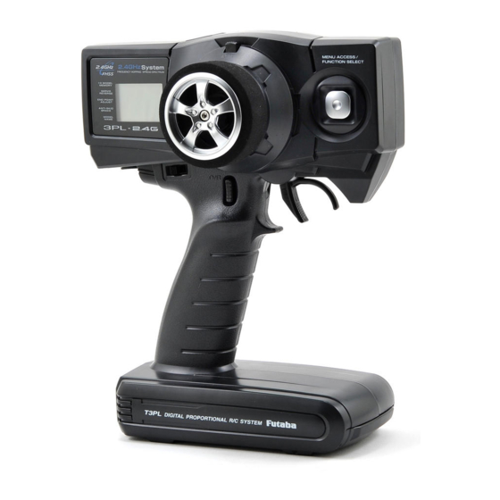
Nomenclature / Handling
Transmitter T3PL-2.4G
Steering Trim Lever (DT1)
(*1)
Adjusts the steering in small increments so the model will run straight.
(*1)
Throttle Trim Lever (DT2)
Adjusts the throttle in small increments so the model will not move at neutral.
LCD s creen
Power switch turned on: Beep confirmation sound is generated and the model name is displayed for about two seconds and then the initial screen appears.
(Initial screen)
‘ y number display
‘!!
y voltage display
n WARNING j
A s w i t h a l l r a d i o f r e q u e n c y transmissions, the strongest area of signal transmission is from the sides of the antenna(builtin). As such, the antenna (arrow direction) should not be pointed directly at the model.
Power Switch
When slid upward, the power is turned on.
Antenna (Built-in)
The antenna is inside of this part.
Select Button
Press the Select button to select the desired function screen.
Steering Wheel
Turn model to left or right.
Channel 3 Switch
Turn channel 3 servo to left or right.
Grip Handle
Throttle Trigger
Control the speed of the model and movement forward and backward.
Steering Dual Rate Lever (D/R)
(*1)
Adjust the vehicle’s steering sensitivity across the entire range.
(*1)
Digital trim DT1, DT2, and D/R operation
Push the lever to the left or right (up or down).
The current position is displayed on the LCD screen for about two seconds.
Each step is indicated by a tone. When the trim exceeds the maximum trim adjustment range, the beep tone will change and the servo will not move any further. Remember, the trims are digital so the position of each trim is remembered for each model separately.
n WARNING l
Do not cover/hold the built-in antenna part of T3PL-2.4G transmitter by your hand during running.
Do not put any conductive plate/sticker on the antenna part.
Otherwise, the operating range may become shorter.
Before Operation
9
Battery Replacement Method
(4 AA size batteries)
1
Remove the battery cover from the transmitter by sliding it in the direction of the arrow in the figure.
2
Remove the used batteries.
3
Load the new AA size batteries.
Pay very close attention to the polarity markings and reinser t accordingly.
4
Slide the battery cover back onto the case. n CAUTION j
A l w ay s b e s u r e y o u r e i n s e r t t h e batteries in the correct polarity order.
If the batteries are loaded incorrectly , the transmitter may be damaged. j
When the transmitter will not be used for any shor t or long period of time, always remove the batteries.
If the batteries do happen to leak , clean the battery case and contacts thoroughly. Make sure the contacts are free of corrosion.
Check:
Turn the power switch on the transmitter to the ON position. Check the battery voltage display on the LCD screen.
If the voltage is low, check the batteries for insufficient contact in the case or incorrect battery polarity.
Low Battery Alarm:
If the transmitter battery voltage drops below 4.2V an alarm will sound and
«LOW» will be displayed on the LCD screen.
The low battery alarm is meant to be a safety feature only. Do NOT operate your radio below 4.5V. Always shut your radio off as soon as possible after the low battery warning tone to avoid loss of control.
10
Before Operation
E.S.C. MC230CR / MC330CR
Checker LED
Pushbutton switch
Applicable motors
(Number of turns is criteria.)
•Use the MC230CR with a motor with 20T or more turns.
•Use the MC330CR with a motor with 13T or more turns.
*If a motor with a number of turns smaller than the above is used, the heat protector and overcurrent protection circuit may operate. The number of turns of the motor is one criteria only. Depending on the running conditions, the protection circuit may operate even if the condition above is satisfied.
(Orange)
(Blue)
Motor connector
Connects to the motor.
(Orange) is positive. (Blue) is negative.
If the motor rotates in the wrong direction, reverse the connections.
(Black)
(Red)
Nicd battery connector
Connects to the running Nicd battery.
(Red) is positive. (Black) is negative.
Nicd battery 6~7 cells (7.2~8.4V)
MC230CR/MC330CR
Power switch
Receiver connector
Connects to the receiver throttle channel.
Miniature screwdriver
Accessory. Use to press the pushbutton switch.
Before Operation
11
Assembly / Adjustment
Receiver and Servo Connection
As you connect the receiver, servos and other components, do so in accordance with the
«Assembly Precautions».
Connection s when an E.S.C. MC230CR or MC330CR i s u s ed.
Connects to Motor
Connects to Battery
E.S.C.
Power Switch
(CH4)
Channel 4 Servo
(CH3)
Channel 3 Servo
Receiver
(CH1)
Steering Servo
Ga s Powered Model
(CH4)
Channel 4 Servo
(CH3)
Receiver
To Receiver
Battery
Power Switch
(CH2)
(CH1)
Channel 3 Servo
Throttle Servo
Steering Servo
Receiver Antenna Installation
Install the R2004GF receiver on the car as follows:
Note:
The operating range may become shorter, depending on where the receiver and the antenna are mounted.
n
WARNING j
Install the antenna in the higher place as shown in the figure.
Keep the antenna as far away from the motor, ESC and other noise sources as possible.
Put the antenna in the antenna tube to protect it.
l
Do not cut the antenna.
Do not bend the coaxial cable. Doing so causes damage.
12
Assembly / Adjustment
R2004GF
Antenna tube
Antenna
Coaxial cable
Assembly Precautions
n WARNING j
Check the receiver, servos, and battery connectors, to be sure they are firmly connected.
If a connector is not fully inserted, vibration may cause the connector to work loose while the model is operating. This will result in loss of control. j
Operate each servo horn over its full stroke and check to see that the linkage does not bind or is not too loose.
Excessive force applied to the servo horn by binding or poor installation may lead to servo problems and result in loss of control. j
(Electric Cars and Boats)
Isolate the receiver from vibration by attaching to the chassis or mounting plate with thick double sided tape.
(Gas Powered Cars and Boats)
Isolate the receiver from vibration by wrapping it in foam rubber or similar type cushioning material. Protect the unit from water damage by placing it in a plastic bag or waterproof radio box.
The receiver contains precision electronic parts. These parts are vulnerable to vibration and shock. Any contact with moisture (water or condensation) may cause receiver malfunction and loss of control.
j
Keep all devices that emit high frequency noise, such as motors, batteries, and wiring that handles heavy current loads, at least 1/2 inch away from the receiver and the receiver antenna.
High frequency noise will cause a decrease in operating range and could cause loss of control.
j
Install electronic speed control heat sinks as well as other components that conduct electricity so they cannot come in contact with aluminum, carbon fiber or other materials that conduct electricity.
If, for example, the speed control came loose while the model was running and touched an aluminum chassis, a short circuit may occur that would cause irreparable damage to the system as well as loss of control.
j
Noise suppression capacitors should be installed on almost all motors.
If the proper capacitors are not installed, high frequency noise will reduce range and cause loss of control along with various other problems. j
Inspect all linkage installations and any point where metal could come in contact with other metal parts. Make sure these parts do not touch other metal parts under vibration.
Should a linkage or other metal parts come in contact with other metal parts under vibration, the high frequency noise generated by this contact will cause interference and possible loss of control.
n
CAUTION l
Do Not disassemble any part of this system that is not specified in the instruction manual.
Futaba will not be responsible for any damage due to improper disassembly of any part of the radio control system.
Assembly / Adjustment
13
How to link the transmitter and the receiver
Each transmitter has an individually assigned, unique ID code. In order to start operation, the receiver must be linked with the ID code of the transmitter with which it is being paired. Once the link is made, the ID code is stored in the receiver and no further linking is necessary unless the receiver needs to be used with another transmitter. (For T/R set, the link is already done at factory.)
Link procedure
1
Bring the transmitter and the receiver close to each other, within one meter.
2
Turn on the transmitter and the receiver.
3
P u s h a n d h o l d t h e L i n k S w i t c h o f t h e receiver.
4
When the link is complete, the LED in the receiver changes to solid green.
*Please refer the table below for LED status vs receiver’s condition.
Link Switch LED
LED status vs receiver’s condition:
No signal reception
Receiving signals
Red : On
Green: On
Receiving signals, but ID is unmatched.
Green: Blink
14
Assembly / Adjustment
Transmitter Set-Up Procedures
*When making these setting adjustments, do so with the motor disconnected or the engine not running.
(Preparations)
Select the model memory that is not used and reset it to the initial values with the model selection and model reset functions.
Model Selection
Model number
( 1 — 0 )
Model name
(Selection key)
Model Reset
Push the DT2 lever up or down for about one second.
All data stored in the current selected model memory is erased.
Servo Horn Installation Instructions
1
Connect the receiver, servos, and other components and then turn on the power switches to the transmitter and receiver.
*Both servos will move to the neutral position.
2
At this time install the servo horn in the manner described in the instruction manual provided with the model this system will be used in.
Steering Servo Reverse
Reversing The Servo Operation Direction
NOR: Normal
REV: Reverse
S h o u l d t h e s e r vo o p e ra t e i n t h e o p p o s i t e direction required for your application, reverse the direction with the servo reversing.
Throttle Servo Reverse
NOR: Normal
REV: Reverse
E.S.C. MC230CR / MC330CR
NEUTRAL, HIGH, AND BRAKE MAX POINTS SETTINGS
(Selection key)
(Selection key)
Set the steering angle adjustment function (ATV) to
100% and the ABS function and acceleration function to OFF using the transmitter throttle channel function.
If the steering angle is too large or the ABS and acceleration functions are on, erroneous operation may occur.
*When using the ABS function, after setting up the MC230CR / MC330CR, stop the reverse function, then turn on the ABS function. If the
ABS function is on, the MC231CR / MC331CR cannot be set up correctly.
Before setting each point, set the transmitter throttle channel trim to neutral.
1
Turn on the power in transmitter -> amp order.
Transmitter throttle operation
MC230CR /MC330CR
(Pushbutton switch operation) (Checker LED)
2
Neutral point setting
N
・ Neutral state
・ Press the pushbutton switch.
(0.5 secs or longer)
(Confirmation beep sounds)
・ Continuous single blink
3
High point setting
N
・
Full high state
・ Press the pushbutton switch.
(Confirmation beep sounds)
・ Continuous double blink
Full High
4
Brake MAX point setting
・ Full brake state
・ Press the pushbutton switch.
(Confirmation beep sounds.)
・ If the LED goes out, setting is complete.
N Full brake
* Since the data is read at the end of setting of all points, the points cannot be set independently.
* If the amp power was turned off during setting, the setting points cannot be memorized. (The previous settings are retained.)
* The confirmation beep sounds only when the motor was connected.
If the LED does not go off but blinks rapidly, setting was not performed normally. Repeat setting from «Neutral point setting».
・ Continuous rapid blink
Assembly / Adjustment
15
3PL-2.4G Functions
Steering Trim (TRM-CH1)
Steering neutral adjustments can be made by moving the Steering trim knob to the left or right.
Racers Tip
When you install a servo, always check to be sure the servo is at its neutral position. Adjust the servo horn hole position and linkage so both are parallel.
When a servo saver is used, place it as close to center position as possible. Be sure the steering trim on the transmitter is at the neutral position.
Servo Saver
Trim Operation And Maximum Travel
Changing the trim can affect the overall settings. When adjustments are made with the trims, recheck your installation for maximum travel. (Steering EPA right side and left side).
Parallel
90
°
Steering Trim
( L25 — 0 — R25 )
Direct Servo Saver Horn
90
°
When Trim usage is extreme
If it takes most of your trim movement to get a servo to the neutral position, reposition the servo horn or servo saver on the servo and inspect your linkage installation.
Throttle Trim (TRM-CH2)
Throttle neutral adjustments can be made moving the throttle trim to the left or right.
Racers Tip
When using an electronic speed control, set the throttle trim to neutral and make adjustments to the speed control. On a gas powered model, set the trim to neutral and adjust the linkage to the point where the carburetor is fully closed in accordance with the engine instruction manual.
Trim Operation and Travel
Trim adjustments will affect the overall servo travel. Check the brake side (backward) movement when changes are made.
When trim movement is extreme
If you use most of the trim movement to get the servo to the neutral position, recenter the servo horn closer to the neutral position and inspect your throttle linkage.
Throttle Trim
( B25 — 0 — F25 )
Carburetor Fully Closed
(Drum Type)
(Slide Type)
Steering D/R
Steering Dual Rates (D/R-CH1)
Use this function to adjust the steering travel of your model. If the model understeers (push) while cornering, add steering by pressing the upper side of the D/R button. When the model oversteers (loose), take away steering by pressing the lower side of the D/R button.
• This function can not be used when 4WS mixing is activated.
(
30 — 100%
)
16
3PL-2.4G Functions
Model Selection/Model Reset (MDL)
The model selection selects the desired model memory from the 10 model memories stored within the transmitter, and the model reset erases all data stored in a specific model memory.
Model Selection
Model number
( 1 — 0 )
Model name
(Selection key)
Model Reset
Push the DT2 lever up or down for about one second.
All data stored in the current selected model memory is erased.
Steering Servo Reversing (REV-CH1)
This function reverses the rotation direction of the Steering servo.
When the trim position deviates from the center, the deviation will be on the opposite side when the servo is reversed.
Steering Servo Reverse
NOR: Normal
REV: Reverse
(Selection key)
Throttle Servo Reversing (REV-CH2)
This function reverses the rotation direction of the throttle servo.
When the trim position deviates from the center, the deviation will be on the opposite side when the servo is reversed.
Throttle Servo Reverse
NOR: Normal
REV: Reverse
(Selection key)
Channel-3 Servo Reversing (REV-CH3)
This function reverses the rotation direction of the channel-3 servo.
Channel-3 Servo Reverse
NOR: Normal
REV: Reverse
(Selection key)
Channel-4 Servo Reversing (REV-CH4)
(This setting screen is displayed when 4WS mixing or Brake mixing is activated.)
This function reverses the rotation direction of the channel-4 servo.
Channel-4 Servo Reverse
NOR: Normal
REV: Reverse
When the trim position deviates from the center, the deviation will be on the opposite side when the servo is reversed.
(Selection key)
3PL-2.4G Functions
17
Steering End Point Adjustment (EPA-CH1)
Use this function to limit the servo movement to the left or right. The servo travel to each side can be independently adjusted. This feature will compensate for any difference in right or left turning a n g l e s o r r a d i u s d u e t o t h e characteristics of your model.
Steering EPA
(Left side)
Range: 0 — 120%
Adjust the travel of the servo while operating the steering wheel each way.
(Right side) n WARNING j
Be sure that the steering linkage does not bind or come in contact with any suspension parts or arms. If unreasonable force is applied to the servo, the servo may be damaged and result in loss of control.
Throttle End Point Adjustment (EPA-CH2)
This function is used to adjust the forward and brake side servo travel. Each direction can be adjusted independent of each other. Use this feature to set the throttle servo travel.
Throttle EPA
Range: 0 — 120%
(Forward side)
Adjust the travel of the servo while operating the throttle trigger each way.
(Brake side) n
WARNING j
Be sure that your throttle linkage does not apply excessive force to the servo.
If your linkage installation causes an unreasonable amount of force to be applied to the servo, the servo may be damaged and result in loss of control.
Channel-3 End Point Adjustment (EPA-CH3)
Use this function to limit the servo movement to the left or right. The servo travel to each side can be independently adjusted.
Channel-3 EPA
Range: 0 — 120%
(Left side)
Adjust the travel of the servo while operating the channel-3 switch each way.
(Right side) n
WARNING j
Be sure that the linkage does not bind or come in contact with any parts or arms. If unreasonable force is applied to the servo, the servo may be damaged and result in loss of control.
18
3PL-2.4G Functions
Channel-4 End Point Adjustment (EPA-CH4)
(This setting screen is displayed when 4WS mixing or Brake mixing is activated.)
Use this function to limit the servo movement to the left or right. The servo travel to each side can be independently adjusted.
Channel-4 EPA
Range: 0 — 120%
(Left side) (Right side) n WARNING j
B e s u r e t h a t t h e l i n k a g e does not bind or come in contact with any par ts or arms. If unreasonable force is applied to the servo, the servo may be damaged and result in loss of control.
(4WS function)
Adjust the travel of the servo while operating the steering wheel each way.
(BRK function)
Adjust the travel of the servo while operating the trigger to the brake side.
(Brake side)
ABS function (ABS-CH2)
This function simulates a full size car’s antilock braking by pulsing the brake on and off rapidly.
Model stops as rapidly as possible without skidding.
• The cycle speed can be selected from FST/MID/SLW.
ABS function
ABS Cycle Speed
OFF: Inhibited
FST: Active (fast)
MID: Active (middle)
SLW: Active (slow)
(Selection key)
Model Name (NAME)
T h i s f u n c t i o n p r o v i d e s a
3-character name for each of the model memories in the transmitter to easily select the correct setup for the model currently in use.
• Clearly label each model for easy selection.
Model Name
Model number
( 1 — 0 )
Model name
(Selection key)
(Selection key)
4WS/BRK Mixing Selection (SMX)
Either 4WS mixing function or
Brake mixing function can be selected on this screen.
Special Mixing Selection
(2 seconds)
(Selection key)
INH: Inhibited
4WS: 4WS mixing
BRK: Brake mixing for second brake
3PL-2.4G Functions
19
4WS Mixing (4WS)
This mixing is used with Crawler and other 4WS specification cars. The 1st channel controls the front side steering and the 4th channel controls the rear side steering.
• The operation mode of the front and rear wheels can be switched by the steering D/R lever (D/R). By pressing the lever up or down, reverse phase (up side) and same phase (down side) can be switched.
• Linkage at 4WS function selection
1. After connecting the linkage, use the servo reverse function to change the direction of operation of the front and rear wheels so that it is the same mode as the operation mode (reverse phase/same phase) being selected.
2. Thereafter, use the end point adjuster to adjust the left and right steering angles.
Brake Mixing (BRK)
Use this mixing when the front and rear brakes must be adjusted independently, such as in 1/5GP cars, etc. This mixing uses the 2nd channel to control the rear brakes and the 4th channel to control the front brakes.
• When braking, mixing is applied to 2nd channel and to 4th channel.
• The set value of A.B.S. function is reflected.
Channel-4 Trim (TRM-4)
(This setting screen is displayed when 4WS mixing or Brake mixing is activated.)
At 4WS mixing function:
The neutral adjustments of the rear steering servo can be made by moving the steering trim (DT1) to the left or right.
Channel-4 Trim
(4WS mixing)
Range:
L25 — 0 — R25
B25 — 0 — F25
(Brake mixing)
At brake mixing function:
The neutral adjustments of the front brake servo can be made by moving the steering trim
(DT1) to the left or right.
Throttle Fail Safe Function
This function moves the throttle servo to a preset position when the receiver cannot receive the signal from the transmitter for some reason.
W h e n t h e s i g n a l f r o m t h e transmitter can be received again, this function automatically resets.
Throttle F/S Function
OFF: Inhibited
***%: F/S position
(Selection key)
F/S position setting
Push the DT2 lever up or down for about one second while operating the throttle trigger to the desired position.
Setting example:
Throttle idle or brake position
*For gasoline engine cars, it is recommended that the fail safe position be set to the direction that applies the brakes.
20
3PL-2.4G Functions
MC230CR/MC330CR
CANCELLING THE REVERSE FUNCTION
The amp reverse function can be cancelled by the following method so that the model can be used even in races that prohibit reverse running. (Brake operation only)
MC230CR / MC330CR
(Pushbutton switch operation) (Power switch)
1
Reverse function cancellation
While pressing the pushbutton switch,
ON set the power switch to ON.
* When desired, you can enable the cancelled reverse function by repeating the operation shown at the left.
(The reverse function is switched alternately.)
BRAKE/REVERSE OPERATING INSTRUCTIONS
Operation can be switched to reverse operation by returning the throttle trigger (or throttle stick) from the brake position to the neutral position.
PROTECTION CIRCUIT OPERATION
The following protection circuits are built into the MC230CR / MC330CR. When a protection circuit operates, remove the cause before operating the model again.
Overcurrent protection
When an overcurrent flows due to an output short circuit, etc., the overcurrent protection circuit automatically limits the current to protect the FET.
Remove the cause of the short circuit, etc. before operating the model again.
Heat protector
Low voltage operation
When abnormal heating of the FET due to an overload, etc. is detected, the heat protector operates so that the speed is gradually reduced.
When the FET temperature drops, the heat protector automatically resets. However, remove the cause of the overheating before operating the model again.
When the Nicd battery voltage drops, this function limits the motor output current and ensures steering operation.
After the speed drops, immediately recover the vehicle.
CHECKER LED DISPLAY
The amp operates linearly in proportion to the amount of forward, reverse, and brake operation. The amp operating state can be checked with the checker LED as shown below.
Operation Checker LED display
Amp power ON
(Reverse operation set)
Single blink
(Single confirmation beep)
(Only brake operation set)
Double blink
(Two confirmation beeps)
High point
Forward
Neutral point
Reverse
/brake
Brake MAX point
Off
On
Off
On
Off
*Becomes brighter nearer the high point.
*Becomes brighter nearer the brake MAX point.
(Amp power left on alarm)
When the transmitter power was turned off first.
* Confirmation beep only sounds when the motor was connected.
Blinks. (Confirmation beep also sounds.)
*Not used with PCM receivers.
*When the transmitter is OFF, this function is not performed in environments such that the servo operates erroneously.
3PL-2.4G Functions
21
Function Map
Power switch turned on
The current model name is displayed for about two seconds.
D i g i tal tr i m DT1, DT2, and D/R d i splay
The current position is displayed on the LCD screen for about two seconds when each digital trim is operated.
Steering Trim Throttle Trim Steering D/R
(L25 — 0 — R25)
(B25 — 0 — F25)
(30 — 100%)
(Initial Screen)
s0RESSTHESELECTBUTTONTOSELECTTHEDESIREDFUNCTIONSCREEN s0RESSITFORABOUTTWOSECONDSTORETURNTOTHEINITIALSCREEN
Model Selection
Model number
(1 — 0)
Model name
(Selection key)
Model Reset
Push the DT2 lever up or down for about one second.
All data stored in the current selected model memory is erased.
Steering Servo Reverse
NOR: Normal
REV: Reverse
(Selection key)
Throttle Servo Reverse
NOR: Normal
REV: Reverse
Channel-3 Servo Reverse
NOR: Normal
REV: Reverse
(Selection key)
s$4AND$4OPERATEONLY
AS THE DATA INPUT KEYS IN
THE PROGRAMMING MODE
4HESE DO NOT OPERATE AS
THETRIMLEVERS
(Selection key)
INH (Special Mix) ACT
Channel-4 Servo Reverse
NOR: Normal
REV: Reverse
(Selection key)
22
Function Map
Steering EPA
Adjust the travel of the servo while operating the steering wheel each way.
Range: 0 — 120%
(Left side)
Throttle EPA
(Right side)
Adjust the travel of the servo while operating the throttle trigger each way.
Range: 0 — 120%
(Forward side)
Channel-3 EPA
(Brake side)
Adjust the travel of the servo while operating the channel-3 switch each way.
Range: 0 — 120%
(Left side)
INH (Special Mix) ACT
Channel-4 EPA
(Left side: 4WD)
(Right side)
Range: 0 — 120%
(Right side: 4WD, Brake side: BRK)
Adjust the travel of the servo while operating the steering wheel or throttle trigger each way.
ABS function
ABS Cycle Speed
OFF: Inhibited
FST: Active (fast)
MID: Active (middle)
SLW: Active (slow)
(Selection key)
Model Name
Model number
(1 — 0)
Model name
(Selection key)
(Selection key)
Special Mixing Selection
INH: Inhibited
4WS: 4WS mixing
BRK: Brake mixing
(Selection key)
(2 seconds)
INH (Special Mix) ACT
Channel-4 Trim
(4WS mixing)
Range:
L25 — 0 — R25
B25 — 0 — F25
(Brake mixing)
Throttle F/S Function
OFF: Inhibited
***%: F/S position
(Selection key)
F/S position setting
To Initial Screen
Push the DT2 lever up or down for about one second while operating the throttle trigger to the desired position.
Sett i ng example :
Throttle idle or brake position
s!LWAYSRETURNTOTHEINITIALSCREENAFTERTHESETTING
Function Map
23
Reference
Ratings
Communication method:
One-way operation system
Maximum operating range:
80m (Optimum condition)
For safety:
F/S (Throttle), ID (About 4 billion ways of pair identifications)
Transmitter T3PL-2.4G
(FHSS system, wheel type, 3+1 channels)
*The 4th channel is used for mixing functions only.
Transmitting frequency:
2.4GHz band
Power requirement:
(Dry cell battery) Penlight x 4(6V)
Current drain:
100mA or less
Transmission antenna:
1/2λ di-pole (Built-in)
Receiver R2004GF:
Servo S3003
Servo S3050
(Standard digital servo)
Power requirement:
6V (common with receiver)
Current drain:
8mA (at 6V / Idle)
Output torque:
6.5kg-cm (90.3oz.-in.) at 6V
Operating speed:
0.16sec/60 degree at 6V
Size:
40.0×20.0×38.1mm (1.57×0.79×1.50in.)
Weight:
49g (1.72oz.)
E.S.C. MC230CR / MC330CR
(FHSS system, 4 channels)
Power requirement:
4.8V or 6V NiCd battery
Size:
26x39x10mm (excluding a projection part)
Weight:
14g
(Standard servo)
Power requirement:
6V (common with receiver)
Current drain:
8mA (at 6V / Idle)
Output torque:
4.1kg-cm (57in.-oz.) at 6V
Operating speed:
0.19sec/60 degree at 6V
Size:
40.4×19.8x36mm (1.59×0.78×1.42in.)
Weight:
37.2g (1.31oz.)
(Electronic speed control)
Operating system:
Forward, reverse, and brake operations are all linear.
Power requirement:
Nicd battery 6-7 cells (7.2 to 8.4V)
PWM frequency:
1.5kHz (fixed)
Setting:
One-touch input by pushbutton switch. Set data is saved to built-in EEPROM.
Current capacity (FET rating):
Forward=90A/200A, reverse=45A/100A
Size:
27.1×33.3×12.8mm (1.07×1.31×0.50in.)
(excluding protruding parts)
Silicon cord gauge size:
AWG16/AWG14 equivalent
Weight:
44/45g (1.55/1.59oz.)
(including connectors and switches)
BEC voltage:
6.0V
NOTE:
This Futaba FHSS system, including the T3PL-
2.4G transmitter and R2004GF receiver, does not work with current Futaba FASST™ systems. Please use the
T3PL-2.4G and R2004GF in pairs. Futaba FASST systems and FHSS systems are not compatible.
24
Reference
*Specifications and ratings are subject to change without prior notice.
Troubleshooting
If your system fails to operate or you experience a short range problem or erratic control, check the table below for possible causes. If after you have followed the suggestions listed the problem is not corrected, return the system to our service department for inspection and repair.
(Item Check)
Transmitter
Battery
Dead battery Change the batteries.
Batteries inserted incorrectly. Reload the batteries in accordance with the polarity markings
Faulty contact Check to see if the contacts are bent and not making good contact
Dirty contacts Clean the contacts and check for corrosion.
Receiver
Battery
Dead battery
Wrong polarity
Replace or recharge
Check connections
Antenna
Near other wiring Move away from wiring
Was antenna cut Request repair
Is the antenna installed correctly Refer to the receiver installation.
Monitor LED
Check the LED of the receiver.
Refer to the «How to link the transmitter and the receiver».
Connector connections
Wiring incorrect Insert all connectors firmly
Loose connections Push the connector in firmly
Binding or loose
Is movement stiff
Linkage
Adjust the linkage in model
Adjust linkage in model
Motor (Electric powered)
Noise problems Install capacitors on motor
Reference
25
Low Battery Alarm
If the transmitter battery voltage drops to 4.2V or less, an audible alarm will sound and «LOW v» will be displayed on the LCD screen.
LCD screen:
Error Displays
n WARNING j
When a low battery alarm is generated, cease operation immediately and retrieve the model. If the battery goes dead while in operation, you will lose control.
Backup Error
If the data is lost for an unknown reason, an audible alarm will sound and «ERR» will be displayed on the LCD screen.
LCD screen: n WARNING j
When a backup error is generated, immediately stop using the system and request repair from the Futaba Service Center. If you continue to use the system, the transmitter may malfunction and cause loss of control.
RF Error
If the RF circuit fails for an unknown reason, an audible alarm will sound and «RF» will be displayed on the LCD screen. Please request repair from the Futaba Service Center.
LCD screen:
26
Reference
When requesting repair
Before requesting repair, read this instruction again and recheck your system. Should the problems continue, request as follows.
(Information needed for repair)
Describe the problem in as much detail as possible and send the letter along with the system in question.
• Symptom (Including the conditions and when the problem occurred)
• R/C System (Send transmitter, receiver and servos)
• Model (Type of model, brand name and model number or kit name)
• Detailed packing list (Make a list of all items sent in for repair)
• Your name, address and telephone number.
(Warranty)
Read the Warranty card.
• When requesting warranty service, send the card or some type of dated proof of purchase.
Hobby Services (U.S. only)
3002 N. Apollo Drive, Suite 1
Champaign, IL 61822 U.S.A.
Phone: (217) 398-0007 www.hobbyservices.com
©Copyright 2010. No part of this manual may be reproduced in any form without prior permission. The contents of this manual are subject to change without prior notice. While this manual has been carefully written, there may be inadvertent errors or omissions. Please contact our service center if you feel that any corrections or clarifications should be made.
FUTABA CORPORATION Phone: +81 475 32 6982, Facsimile: +81 475 32 6983
1080 Yabutsuka, Chosei-mura, Chosei-gun, Chiba 299-4395, Japan
1M23N23002 ©FUTABA CORPORATION 2010, 7 (1)
Reference
27
R

1M23N23002
3PL-2.4G
3-channel, FHSS
Radio control system
for Cars
I
NSTRUCTION
M
ANUAL
R
Digital Proportional R/C System
3-х канальная аппаратура Futaba 3PL FHSS (с приемником) 2.4G — FU3PLR2004GFID: 39199
ID: 39199Артикул: FU3PLR2004GF
Система радиоуправления 3-х канальная 2.4 ГГц Futaba
Компьютерная 3-х канальная система радиоуправления с технологией передачи данных на частоте 2.4Ghz. В аппаратуре предусмотрен микс для краулеров и моделей 5 масштаба! Благодаря применению технологии передачи данных на частоте 2.4Ghz передатчик использует всего 4 батарейки типа АА!
Комплектация:
- Передатчик управления Futaba 3PL FHSS 2.4Ghz
- Приёмник Futaba R2004GF FHSS 2.4Ghz
Необходимо докупить:
- 4 батарейки (аккумулятора) типа АА
- ХарактеристикиХар-ки
- Доставка
- Оплата
- Отзывы (0)
- Вопросы (0)
| Рабочая частота: | 2.4G |
| Количество каналов: | 3 |
| Бренд (комплектующие): | Futaba |
Магазин RC-TODAY.RU осуществляет доставку заказов как собственной курьерской службой, так и различными транспортными компаниями.
Доставка по Москве
Самовывоз из магазина RC-TODAY.RU —БЕСПЛАТНО
Мы находимся:г. Москва, 6-й монетчиковский пер., д. 8с1 (3 минуты пешком от метро Павелецкая)
Время работы: Ежедневно с 09:00 до 21:00
Сделайте заказ любым удобным для Вас способом, наш менеджер свяжется с Вами для согласования даты и времени Вашего приезда.
Как только заказ будет скомплектован, мы Вам позвоним и отправим смс-уведомление.
В пределах МКАД, при заказе от 7000 рублей —Бесплатно, при оплате на сайте
В пределах МКАД, при заказе до 7000 рублей —300 руб.
Если вы находитесь за МКАД, то цена доставки зависит от адреса и рассчитывается в корзине.
Срок доставки — 1-2 дня. В рабочие дни минимальный интервал доставки — 3 часа, в выходные и праздничные дни — 8 часов.
Если Вы находитесь за МКАД, то срок доставки — 1-2 дня, а минимальный интервал доставки — 8 часов.
Просим учесть, что крупногабаритные товары мы доставляем только до подъезда. Подъём до квартиры осуществляется за отдельную плату.
Доставка по России
СДЭК
cdek.ru
Оплата заказа возможна наложенным платежом. Срок доставки 2-14 рабочих дней, в зависимости от удалённости города.
EMS-Почта России
pochta.ru/emspost
Оплата заказа возможна наложенным платежом. Срок доставки 5-14 рабочих дней, в зависимости от удалённости города.
Почта России
pochta.ru
Отправка заказа только по полной предоплате. Срок доставки 1-10 рабочих дней, в зависимости от удалённости города.
Деловые линии, Байкал сервис, ПЭК и любые другие ТК
Если Вы знаете транспортную компанию в своём городе, которая устраивает Вас больше, чем предложенные нами, просто сообщите нам об этом, и мы отправим Ваш заказ через неё. Если указанная Вами транспортная компания не предоставляет возможности оплаты заказа при получении, необходимо сделать предоплату за заказ в полном объёме. Доставка, как правило, оплачивается при получении заказа. Сроки доставки зависят от ТК и удалённости региона. При этом забор транспортной компанией с нашего склада оплачивается клиентом вне зависимости от стоимости заказа.
Стоимость доставки зависит от веса и цены товара и рассчитывается оператором при подтверждении заказа.
Самовывоз из пунктов выдачи
Практически в каждом городе у нас есть пункт выдачи заказов от наших партнёров. Уточнить адреса и контакты пункта выдачи Вы можете любым удобным для Вас способом: по телефону, в онлайн чате, а также при оформлении заказа в корзине.
Оплата наличными
Оплата производится наличными средствами курьеру при получении заказа. Если для Вас это самый удобный вариант оплаты, просто выберите «Оплата при доставке» при оформлении заказа или, если Вы оформляете заказ по телефону, сообщите об этом менеджеру. Эта опция доступна не только для жителей Москвы и Санкт-Петербурга, но и для жителей остальных регионов России. Оплачивайте свои заказы по факту получения. Ваш комфорт – наш приоритет.
Оплата через сайт
Вы можете оплатить свой заказ непосредственно при оформлении заказа. Для этого нужно выбрать способ оплаты «Картами Visa, MasterСard» или «WebMoney, Яндекс.Деньги, QIWI». После этого Вы автоматически перейдете на сайт платежной системы и сможете произвести оплату любым удобным для Вас способом. Если вы оформляете заказ по телефону, попросите менеджера отправить Вам ссылку на оплату заказа онлайн на Вашу электронную почту. Перейдя по этой ссылке, Вы попадете на сайт платежной системы, где сможете оплатить заказ.
Оплата банковским переводом
При оформлении заказа выбираете тип оплаты «Банковский перевод». В форме заказа необходимо заполнить электронную почту – на нее мы отправим Вам ссылку на счет с нашими реквизитами. Если вы оформляете заказ по телефону, попросите менеджера прислать Вам счет на оплату. Оплатить счет Вы можете в любом банке. Пожалуйста, указывайте в комментарии к платежу номер Вашего заказа!
Покупка в кредит
На нашем сайте есть возможность покупки в кредит! Теперь это совсем не сложно — всего 5 шагов и в течение 2-х минут Вам сообщат решение по онлайн кредиту. Или закажите заказ звонка и вам во всем поможет менеджер банка! Кредит от 5000 до 300 000 тысяч рублей. Процентная ставка от 19 до 26%. Все условия кредитования вы можете узнать во вкладке КупитьВкредит.

Хит продаж

Батарейки типа АА Energizer Plus повышенной емкости