-
Contents
-
Table of Contents
-
Troubleshooting
-
Bookmarks
Quick Links
GA-P67X-UD3-B3
User’s Manual
Rev. 1001
12ME-P67XD3B-1001R
Related Manuals for Gigabyte GA-P67X-UD3-B3
Summary of Contents for Gigabyte GA-P67X-UD3-B3
-
Page 1
GA-P67X-UD3-B3 User’s Manual Rev. 1001 12ME-P67XD3B-1001R… -
Page 3: Identifying Motherboard Revision
GIGABYTE’s prior written permission. Documentation Classifications In order to assist in the use of this product, GIGABYTE provides the following types of documentations: For quick set-up of the product, read the Quick Installation Guide included with the product.
-
Page 4: Table Of Contents
Table of Contents Box Contents ……………………6 Optional Items …………………….6 GA-P67X-UD3-B3 Motherboard Layout ……………..7 GA-P67X-UD3-B3 Motherboard Block Diagram …………8 Chapter 1 Hardware Installation ………………9 Installation Precautions ………………. 9 1-2 Product Specifications ………………. 10 Installing the CPU and CPU Cooler…………… 13 1-3-1 Installing the CPU ………………..13 1-3-2 Installing the CPU Cooler ………………15 Installing the Memory ………………
-
Page 5
Chapter 3 Drivers Installation ………………59 Installing Chipset Drivers …………….59 Application Software ………………60 Technical Manuals ………………60 Contact………………….61 System ………………….61 Download Center ………………. 62 New Utilities ………………..62 Chapter 4 Unique Features……………….63 Xpress Recovery2 ………………63 BIOS Update Utilities ………………66 4-2-1 Updating the BIOS with the Q-Flash Utility ………… -
Page 6: Box Contents
Box Contents GA-P67X-UD3-B3 motherboard Motherboard driver disk User’s Manual Quick Installation Guide Four SATA cables I/O Shield One 2-Way SLI bridge connector • The box contents above are for reference only and the actual items shall depend on the product package you obtain. The box contents are subject to change without notice.
-
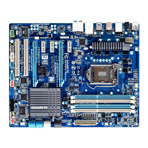
Page 7: Ga-P67X-Ud3-B3 Motherboard Layout
GA-P67X-UD3-B3 Motherboard Layout SYS_FAN1 KB_MS_USB CPU_FAN PHASE LED ATX_12V_2X4 R_SPDIF LGA1155 USB_1394 R_USB PWR_FAN R_USB30 USB_LAN Etron EJ168 AUDIO PCIEX1_1 B_BIOS GA-P67X-UD3-B3 M_BIOS Realtek PCIEX16 RTL8111E GSATA3_7 Marvell 88SE9172 PCIEX1_2 GSATA3_6 SATA3_1 PCIEX1_3 SATA3_0 Intel ® CODEC SATA2_3 SATA2_2 PCIEX8 SATA2_5 SATA2_4 PCI1…
-
Page 8: Ga-P67X-Ud3-B3 Motherboard Block Diagram
GA-P67X-UD3-B3 Motherboard Block Diagram PCIe CLK CPU CLK+/- (100 MHz) (100 MHz) DDR3 2133/1866/1600/1333/1066 MHz LGA1155 2 PCI Express x8 1 PCI Express x16 Dual Channel Memory 2 USB 3.0/2.0 2 USB 3.0/2.0 Interface Switch Etron Etron EJ168 EJ168 PCI Express Bus 2 SATA 6Gb/s RJ45 PCI Express Bus…
-
Page 9: Chapter 1 Hardware Installation
Chapter 1 Hardware Installation Installation Precautions The motherboard contains numerous delicate electronic circuits and components which can become damaged as a result of electrostatic discharge (ESD). Prior to installation, carefully read the user’s manual and follow these procedures: Prior to installation, do not remove or break motherboard S/N (Serial Number) sticker or •…
-
Page 10: Product Specifications
Dual channel memory architecture Š Support for DDR3 DDR3 2133/1866/1600/1333/1066 MHz memory modules Š Support for non-ECC memory modules Š Support for Extreme Memory Profile (XMP) memory modules Š (Go to GIGABYTE’s website for the latest supported memory speeds and memory modules.) Audio Realtek ALC889 codec Š High Definition Audio Š 2/4/5.1/7.1-channel Š…
-
Page 11
Storage Interface 1 x Marvell 88SE9172 chip: Š 2 x SATA 6Gb/s connectors (GSATA3_6, GSATA3_7) supporting up to 2 SATA 6Gb/s devices Support for SATA RAID 0 and RAID 1 Chipset: Š Up to 14 USB 2.0/1.1 ports (8 on the back panel, 6 via the USB brackets connected to the internal USB headers) 2 x Etron EJ168 chips: Š… -
Page 12
Support for Microsoft Windows 7/Vista/XP Š ® System Form Factor ATX Form Factor; 30.5cm x 24.4cm Š * GIGABYTE reserves the right to make any changes to the product specifications and product-related information without prior notice. Hardware Installation — 12 -… -
Page 13: Installing The Cpu And Cpu Cooler
Read the following guidelines before you begin to install the CPU: Make sure that the motherboard supports the CPU. • (Go to GIGABYTE’s website for the latest CPU support list.) Always turn off the computer and unplug the power cord from the power outlet before installing •…
-
Page 14
B. Follow the steps below to correctly install the CPU into the motherboard CPU socket. Before installing the CPU, make sure to turn off the computer and unplug the power cord from the power outlet to prevent damage to the CPU. Step 1: Step 2: Gently press the CPU socket lever handle down… -
Page 15: Installing The Cpu Cooler
1-3-2 Installing the CPU Cooler Follow the steps below to correctly install the CPU cooler on the motherboard. (The following procedure uses Intel boxed cooler as the example cooler.) ® Male Push Direction of the Arrow Sign on The Top the Male Push of Female Push Pin…
-
Page 16: Installing The Memory
Make sure that the motherboard supports the memory. It is recommended that memory of the • same capacity, brand, speed, and chips be used. (Go to GIGABYTE’s website for the latest supported memory speeds and memory modules.) Always turn off the computer and unplug the power cord from the power outlet before installing •…
-
Page 17: Installing A Memory
1-4-2 Installing a Memory Before installing a memory module, make sure to turn off the computer and unplug the power cord from the power outlet to prevent damage to the memory module. DDR3 and DDR2 DIMMs are not compatible to each other or DDR DIMMs. Be sure to install DDR3 DIMMs on this motherboard.
-
Page 18: Installing An Expansion Card
Installing an Expansion Card Read the following guidelines before you begin to install an expansion card: • Make sure the motherboard supports the expansion card. Carefully read the manual that came with your expansion card. • Always turn off the computer and unplug the power cord from the power outlet before installing an expansion card to prevent hardware damage.
-
Page 19: Setting Up Ati Crossfirex ™ /Nvidia Sli Configuration
Setting up ATI CrossFireX /NVIDIA SLI Configuration ™ A. System Requirements — Windows 7, Windows Vista or Windows XP operating system — A CrossFireX/SLI-supported motherboard with two PCI Express x16 slots and correct driver — Two CrossFireX/SLI-ready graphics cards of identical brand and chip and correct driver — One CrossFire /SLI bridge connector (Note)
-
Page 20: Back Panel Connectors
Back Panel Connectors USB 2.0/1.1 Port The USB port supports the USB 2.0/1.1 specification. Use this port for USB devices such as a USB key- board/mouse, USB printer, USB flash drive and etc. PS/2 Keyboard/Mouse Port Use this port to connect a PS/2 mouse or keyboard. Optical S/PDIF Out Connector This connector provides digital audio out to an external audio system that supports digital optical audio. Before using this feature, ensure that your audio system provides an optical digital audio in connector.
-
Page 21
Center/Subwoofer Speaker Out Jack (Orange) Use this audio jack to connect center/subwoofer speakers in a 5.1/7.1-channel audio configuration. Rear Speaker Out Jack (Black) Use this audio jack to connect rear speakers in a 4-channel audio configuration. Side Speaker Out Jack (Gray) Use this audio jack to connect side speakers in a 4/5.1/7.1-channel audio configuration. Line In Jack (Blue) The default line in jack. Use this audio jack for line in devices such as an optical drive, walkman, etc. Line Out Jack (Green) The default line out jack. -
Page 22: Internal Connectors
Internal Connectors ATX_12V_2X4 F_PANEL F_AUDIO CPU_FAN SPDIF_O SYS_FAN1/2 F_USB1/F_USB2/F_USB3 PWR_FAN F_USB30 F_1394 SATA3_0/1 CLR_CMOS SATA2_2/3/4/5 PHASE LED GSATA3_6/7 COMA Read the following guidelines before connecting external devices: First make sure your devices are compliant with the connectors you wish to connect. •…
-
Page 23
1/2) ATX_12V_2X4/ATX (2×2 12V Power Connector and 2×12 Main Power Connector) With the use of the power connector, the power supply can supply enough stable power to all the com- ponents on the motherboard. Before connecting the power connector, first make sure the power supply is turned off and all devices are properly installed. The power connector possesses a foolproof design. Connect the power supply cable to the power connector in the correct orientation. -
Page 24: Bat Battery
3/4/5) CPU_FAN/SYS_FAN1/SYS_FAN2/PWR_FAN (Fan Headers) The motherboard has a 4-pin CPU fan header (CPU_FAN), a 4-pin (SYS_FAN2) and a 3-pin (SYS_FAN1) system fan headers, and a 3-pin power fan header (PWR_FAN). Most fan headers possess a foolproof insertion design. When connecting a fan cable, be sure to connect it in the correct orientation (the black connector wire is the ground wire).
-
Page 25
7) SATA3_0/1 (SATA 6Gb/s Connectors, Controlled by P67 Chipset) The SATA connectors conform to SATA 6Gb/s standard and are compatible with SATA 3Gb/s and SATA 1.5Gb/s standard. Each SATA connector supports a single SATA device. The SATA3_0 and SATA3_1 connectors support RAID 0 and RAID 1. RAID 5 and RAID 10 can be implemented on the two connec- tors with the SATA2_2/3/4/5 connector . Refer to Chapter 5, «Configuring SATA Hard Drive(s),» for (Note) -
Page 26
9) GSATA3_6/7 (SATA 6Gb/s Connectors, Controlled by Marvell 88SE9172 Chip) The SATA connectors conform to SATA 6Gb/s standard and are compatible with SATA 3Gb/s and SATA 1.5Gb/s standard. Each SATA connector supports a single SATA device. The Marvell 88SE9172 chip supports RAID 0 and RAID 1. Refer to Chapter 5, «Configuring SATA Hard Drive(s),» for instructions on configuring a RAID array. -
Page 27: F_Panel Front Panel Header
11) F_PANEL (Front Panel Header) Connect the power switch, reset switch, speaker, chassis intrusion switch/sensor and system status indicator on the chassis to this header according to the pin assignments below. Note the positive and negative pins before connecting the cables. Message/Power/ Power Speaker…
-
Page 28
12) F_AUDIO (Front Panel Audio Header) The front panel audio header supports Intel High Definition audio (HD) and AC’97 audio. You may connect your chassis front panel audio module to this header. Make sure the wire assignments of the module con- nector match the pin assignments of the motherboard header. Incorrect connection between the module connector and the motherboard header will make the device unable to work or even damage it. For HD Front Panel Audio: For AC’97 Front Panel Audio: Pin No. -
Page 29
14) F_USB1/F_USB2/F_USB3 (USB 2.0/1.1 Headers) The headers conform to USB 2.0/1.1 specification. Each USB header can provide two USB ports via an optional USB bracket. For purchasing the optional USB bracket, please contact the local dealer. Pin No. Definition Power (5V) Power (5V) USB DX- USB DY- USB DX+ USB DY+ No Pin 15) F_USB30 (USB 3.0/2.0 Header) The header conforms to USB 3.0/2.0 specification. Each USB header can provide two USB ports . -
Page 30: Clear Cmos Jumper
16) F_1394 (IEEE 1394a Header) The header conforms to IEEE 1394a specification. The IEEE 1394a header can provide one IEEE 1394a port via an optional IEEE 1394a bracket. For purchasing the optional IEEE 1394a bracket, please con- tact the local dealer. Pin No. Definition TPA+ TPA- GND- TPB+ TPB- Power (12V) Power (12V) No Pin •…
-
Page 31
18) PHASE LED The number of lighted LEDs indicates the CPU loading. The higher the CPU loading, the more the number of lighted LEDs. To enable the Phase LED display function, please first enable Dynamic Energy Saver 2. Refer to Chapter 4, «Dynamic Energy Saver 2,» for more details. ™ ™ F_USB30 F_AUDIO(H) DB_PORT 19) TPM (Trusted Platform Module Header) You may connect a TPM (Trusted Platform Module) to this header. -
Page 32
Hardware Installation — 32 -… -
Page 33: Chapter 2 Bios Setup
To see more advanced BIOS Setup menu options, you can press <Ctrl> + <F1> in the main menu of the BIOS Setup program. To upgrade the BIOS, use either the GIGABYTE Q-Flash or @BIOS utility. Q-Flash allows the user to quickly and easily upgrade or back up BIOS without entering the operating •…
-
Page 34: Startup Screen
Startup Screen The following screens may appear when the computer boots. A. The LOGO Screen (Default) Function Keys B. The POST Screen Award Modular BIOS v6.00PG Copyright (C) 1984-2011, Award Software, Inc. P67X-UD3-B3 E17x Motherboard Model BIOS Version Function Keys <DEL>: BIOS Setup <F9>: XpressRecovery2 <F12>: Boot Menu <End>: Qflash 03/08/2011-P67-7A89VG0UC-00 Function Keys:…
-
Page 35: The Main Menu
The Main Menu Once you enter the BIOS Setup program, the Main Menu (as shown below) appears on the screen. Use ar- row keys to move among the items and press <Enter> to accept or enter a sub-menu. (Sample BIOS Version: E17x) CMOS Setup Utility-Copyright (C) 1984-2011 Award Software MB Intelligent Tweaker(M.I.T.) Load Fail-Safe Defaults…
-
Page 36
The Functions of the <F11> and <F12> keys (For the Main Menu Only) F11: Save CMOS to BIOS This function allows you to save the current BIOS settings to a profile. You can create up to 8 profiles (Profile 1-8) and name each profile. First enter the profile name (to erase the default profile name, use the SPACE key) and then press <Enter> to complete. F12: Load CMOS from BIOS If your system becomes unstable and you have loaded the BIOS default settings, you can use this function to load the BIOS settings from a profile created before, without the hassles of reconfiguring the BIOS settings. First select the profile you wish to load, then press <Enter> to complete. -
Page 37: Mb Intelligent Tweaker(M.i.t.)
MB Intelligent Tweaker(M.I.T.) CMOS Setup Utility-Copyright (C) 1984-2011 Award Software MB Intelligent Tweaker(M.I.T.) Item Help M.I.T Current Status [Press Enter] Menu Level Advanced Frequency Settings [Press Enter] Advanced Memory Settings [Press Enter] Advanced Voltage Settings [Press Enter] …
-
Page 38: Cpu Clock Ratio
M.I.T. Current Status This screen provides information on CPU/memory frequencies/parameters. Advanced Frequency Settings CMOS Setup Utility-Copyright (C) 1984-2011 Award Software Advanced Frequency Settings Item Help CPU Clock Ratio [31X] Menu Level CPU Frequency 3.10GHz (100×31) Advanced CPU Core Features [Press Enter] >>>>>…
-
Page 39
PWM Frequency Control Allows you to alter the PWM frequency. Auto lets the BIOS automatically configure this setting. (Default: Auto) CPU Over Current Protection Allows you to set the maximum over-current value for CPU over-current protection. (Default: +50%) Internal CPU PLL Overvoltage Enabled allows CPU PLL voltage to operate at a higher value. Disabled allows CPU PLL voltage to operate at default value. -
Page 40
C3/C6 State Support (Note 1) Allows you to determine whether to let the CPU enter C3/C6 mode in system halt state. When enabled, the CPU core frequency and voltage will be reduced during system halt state to decrease power con- sumption. -
Page 41
Memory Frequency(Mhz) The first memory frequency value is the normal operating frequency of the memory being used; the second is the memory frequency that is automatically adjusted according to the BCLK/DMI/PEG Frequency(0.1MHz) and System Memory Multiplier settings. Advanced Memory Settings CMOS Setup Utility-Copyright (C) 1984-2011 Award Software Advanced Memory Settings Item Help… -
Page 42
Rank Interleaving Enables or disables memory rank interleaving. Enabled allows the system to simultaneously access dif- ferent ranks of the memory to increase memory performance and stability. Auto lets the BIOS automati- cally configure this setting. (Default: Auto) >>>>> Channel A/B Timing Settings CMOS Setup Utility-Copyright (C) 1984-2011 Award Software Channel A Timing Settings Item Help >>>>>… -
Page 43
tRFC Options are: Auto (default), 1~255. tRTP Options are: Auto (default), 1~15. tFAW Options are: Auto (default), 1~63. Command Rate(CMD) Options are: Auto (default), 1~3. >>>>> Channel A/B Misc Timing Control IO Latency Options are: Auto (default), 1~31. Round Trip Latency Options are: Auto (default), 1~255. -
Page 44: Miscellaneous Settings
>>> MCH/ICH CPU PLL The default is Auto. >>> DRAM DRAM Voltage The default is Auto. DRAM VRef. The default is Auto. DRAM Termination The default is Auto. Ch-A Data VRef. The default is Auto. Ch-B Data VRef. The default is Auto. Ch-A Address VRef.
-
Page 45: Standard Cmos Features
Standard CMOS Features CMOS Setup Utility-Copyright (C) 1984-2011 Award Software Standard CMOS Features Item Help Date (mm:dd:yy) Tue, Mar. 8 2011 Menu Level Time (hh:mm:ss) 22:31:24 IDE Channel 0 Master [None] IDE Channel 0 Slave [None] IDE Channel 1 Master [None] …
-
Page 46
The following fields display your hard drive specifications. If you wish to enter the parameters manually, refer to the information on the hard drive. Capacity Approximate capacity of the currently installed hard drive. Cylinder Number of cylinders. Head Number of heads. Precomp Write precompensation cylinder. Landing Zone Landing zone. Sector Number of sectors. Halt On Allows you to determine whether the system will stop for an error during the POST. -
Page 47: Advanced Bios Features
Advanced BIOS Features CMOS Setup Utility-Copyright (C) 1984-2011 Award Software Advanced BIOS Features Item Help Hard Disk Boot Priority [Press Enter] Menu Level Quick Boot [Disabled] EFI CD/DVD Boot Option [Auto] First Boot Device [Hard Disk] Second Boot Device [CDROM] Third Boot Device [USB-FDD]…
-
Page 48
Allows you to set a delay time for the BIOS to initialize the hard drive as the system boots up. The ad- justable range is from 0 to 15 seconds. (Default: 0) Full Screen LOGO Show Allows you to determine whether to display the GIGABYTE Logo at system startup. Disabled displays normal POST message. (Default: Enabled) Init Display First Specifies the first initiation of the monitor display from the installed PCI graphics card or the PCI Express graphics card. -
Page 49: Integrated Peripherals
Enables or disables the X.H.D function for the SATA controllers integrated in the Intel P67 Chipset. When set to Enabled, the PCH SATA Control Mode item below will be set to RAID(XHD) automatically. For details on using the GIGABYTE X.H.D utility, refer to Chaper 4, «eXtreme Hard Drive (X.H.D).» (Default: Disabled)
-
Page 50
USB Legacy Function Allows USB keyboard to be used in MS-DOS. (Default: Enabled) USB Storage Function Determines whether to detect USB storage devices, including USB flash drives and USB hard drives during the POST. (Default: Enabled) Azalia Codec Enables or disables the onboard audio function. (Default: Auto) If you wish to install a 3rd party add-in audio card instead of using the onboard audio, set this item to Disabled. -
Page 51
When a Cable Problem Occurs… If a cable problem occurs on a specified pair of wires, the Status field will show Short and then length shown will be the approximate distance to the fault or short. Example: Part1-2 Status = Short / Length Explanation: A fault or short might occur at about 2m on Part 1-2. Note: Part 4-5 and Part 7-8 are not used in a 10/100 Mbps environment, so their Status fields will show Open, and the length shown is the approximate length of the attached LAN cable. -
Page 52: Power Management Setup
Power Management Setup CMOS Setup Utility-Copyright (C) 1984-2011 Award Software Power Management Setup Item Help ACPI Suspend Type [S3(STR)] Menu Level Soft-Off by PWR-BTTN [Instant-Off] PME Event Wake Up [Enabled] Power On by Ring [Enabled] Resume by Alarm [Disabled] Date (of Month) Alarm Everyday Time (hh:mm:ss) Alarm 0 : 0 : 0…
-
Page 53
Resume by Alarm Determines whether to power on the system at a desired time. (Default: Disabled) If enabled, set the date and time as following: Date (of Month) Alarm: Turn on the system at a specific time on each day or on a specific day in a month. Time (hh: mm: ss) Alarm: Set the time at which the system will be powered on automatically. Note: When using this function, avoid inadequate shutdown from the operating system or removal of the AC power, or the settings may not be effective. -
Page 54: Pc Health Status
PC Health Status CMOS Setup Utility-Copyright (C) 1984-2011 Award Software PC Health Status Item Help Reset Case Open Status [Disabled] Menu Level Case Opened Vcore 1.172V DDR15V 1.536V +12V 11.779V Vcc3 3.205V 5.042V 1.076V Current System Temperature Current CPU Temperature Current CPU FAN Speed 3375 RPM Current SYSTEM FAN2 Speed…
-
Page 55
Current System/CPU Temperature Displays current System/CPU temperature. Current CPU/SYSTEM/POWER FAN Speed (RPM) Displays current CPU/system/power fan speed. CPU Warning Temperature Sets the warning threshold for CPU temperature. When CPU temperature exceeds the threshold, BIOS will emit warning sound. Options are: Disabled (default), 60 C/140 F, 70 C/158… -
Page 56: Load Fail-Safe Defaults
Load Fail-Safe Defaults CMOS Setup Utility-Copyright (C) 1984-2011 Award Software MB Intelligent Tweaker(M.I.T.) Load Fail-Safe Defaults Standard CMOS Features Load Optimized Defaults Advanced BIOS Features Set Supervisor Password Integrated Peripherals Set User Password Power Management Setup Save &…
-
Page 57: Set Supervisor/User Password
2-11 Set Supervisor/User Password CMOS Setup Utility-Copyright (C) 1984-2011 Award Software MB Intelligent Tweaker(M.I.T.) Load Fail-Safe Defaults Standard CMOS Features Load Optimized Defaults Advanced BIOS Features Set Supervisor Password Integrated Peripherals Set User Password Power Management Setup Save &…
-
Page 58: Save & Exit Setup
2-12 Save & Exit Setup CMOS Setup Utility-Copyright (C) 1984-2011 Award Software MB Intelligent Tweaker(M.I.T.) Load Fail-Safe Defaults Standard CMOS Features Load Optimized Defaults Save to CMOS and EXIT (Y/N)? Y Advanced BIOS Features Set Supervisor Password Integrated Peripherals Set User Password …
-
Page 59: Chapter 3 Drivers Installation
• After «Xpress Install» installs all of the drivers, a dialog box will appear asking whether to install new GIGABYTE utilities. Click Yes to automatically install the utilities. Or click No if you want to manually select the utilities to install on the Application Software page later.
-
Page 60: Application Software
Application Software This page displays all the utilities and applications that GIGABYTE develops and some free software. You can click the Install button on the right of an item to install it. Technical Manuals This page provides GIGABYTE’s application guides, content descriptions for this driver disk, and the mother- board manuals.
-
Page 61: Contact
Contact For the detailed contact information of the GIGABYTE Taiwan headquarter or worldwide branch offices, click the URL on this page to link to the GIGABYTE website. System This page provides the basic system information. — 61 — Drivers Installation…
-
Page 62: Download Center
The latest version of the BIOS, drivers, or applications will be displayed. New Utilities This page provides a quick link to GIGABYTE’s lately developed utilities for users to install. You can click the Install button on the right of an item to install it.
-
Page 63: Chapter 4 Unique Features
Chapter 4 Unique Features Xpress Recovery2 Xpress Recovery2 is a utility that allows you to quickly compress and back up your system data and perform restoration of it. Supporting NTFS, FAT32, and FAT16 file systems, Xpress Recovery2 can back up data on PATA and SATA hard drives and restore it.
-
Page 64
Step 3: Step 4: When partitioning your hard drive, make sure to After the operating system is installed, click Start, leave unallocated space (10 GB or more is recom- right-click the Computer and select Manage. Go to mended; actual size requirements vary, depending Disk Management to check disk allocation. -
Page 65
D. Using the Restore Function in Xpress Recovery2 Select RESTORE to restore the backup to your hard drive in case the system breaks down. The RESTORE option will not be present if no backup is created before. E. Removing the Backup Step 1: Step 2: If you wish to remove the backup file, select… -
Page 66: Bios Update Utilities
BIOS Update Utilities GIGABYTE motherboards provide two unique BIOS update tools, Q-Flash and @BIOS . GIGABYTE ™ ™ Q-Flash and @BIOS are easy-to-use and allow you to update the BIOS without the need to enter MS-DOS mode. Additionally, this motherboard features the DualBIOS design, which enhances protection for the ™…
-
Page 67
B. Updating the BIOS When updating the BIOS, choose the location where the BIOS file is saved. The following procedure as- sumes that you save the BIOS file to a USB flash drive. Step 1: 1. Insert the USB flash drive containing the BIOS file into the computer. In the main menu of Q-Flash, use the up or down arrow key to select Update BIOS from Drive and press <Enter>. •… -
Page 68
Step 4: Press <Esc> and then <Enter> to exit Q-Flash and reboot the system. As the system boots, you should see the new BIOS version is present on the POST screen. Step 5: During the POST, press <Delete> to enter BIOS Setup. Select Load Optimized Defaults and press <Enter> to load BIOS defaults. -
Page 69: Updating The Bios With The @Bios Utility
BIOS or a system that is unable to start. Do not use the G.O.M. (GIGABYTE Online Management) function when using @BIOS. GIGABYTE product warranty does not cover any BIOS damage or system failure resulting from an inad- equate BIOS flashing.
-
Page 70: Easytune 6
EasyTune 6 GIGABYTE’s EasyTune 6 is a simple and easy-to-use interface that allows users to fine-tune their system settings or do overclock/overvoltage in Windows environment. The user-friendly EasyTune 6 interface also includes tabbed pages for CPU and memory information, letting users read their system-related information without the need to install additional software. The EasyTune 6 Interface…
-
Page 71: Dynamic Energy Saver ™ 2
The Dynamic Energy Saver 2 Interface ™ A. Meter Mode In Meter Mode, GIGABYTE Dynamic Energy Saver 2 shows how much power they have saved in a set pe- ™ riod of time. 12 13 14 Meter Mode — Button Information Table…
-
Page 72
B. Total Mode In Total Mode, users are able to see how much total power savings they have accumulated in a set period of time since activating Dynamic Energy Saver 2 for the first time ™ (Note 3) 11 12 13 Total Mode — Button Information Table Button Description Dynamic Energy Saver On/Off Switch (Default: Off) Current CPU Power Consumption… -
Page 73: Q-Share
Q-Share, you are able to share your data with computers on the same network, making full use of Internet resources. Directions for using Q-Share After installing Q-Share from the motherboard driver disk, go to Start>All Programs>GIGABYTE>Q-Share. exe to launch the Q-Share tool. Find the Q-Share icon in the notification area and right-click on this icon to configure the data sharing settings.
-
Page 74: Smart 6
Smart 6 ™ GIGABYTE Smart 6 is designed with user-friendliness in mind, and offers a combination of 6 innovative ™ (Note 1) software utilities that provide easier and smarter PC system management. Smart 6 allows you to speed up ™…
-
Page 75
SMART Recovery 2 Smart Recovery 2 allows you to back up a partition as an image file every hour. You can use these images to restore your system or files when needed. The Smart Recovery 2 main menu: Button Function Settings Allows you to select the source and destination partition Backup Now Allows you to perform the backup immediately File Recovery… Allows you to recover your files from the backup image System Recovery… Allows you to recover your system from the backup image •… -
Page 76
Recovering your system with Smart Recovery 2 (Windows 7 only): Steps: 1. Click the System Recovery button on the main menu. 2. Select the partition where your backup is saved. 3. Use the time slider to select a time point. 4. -
Page 77
SMART Recorder SMART Recorder monitors and records the activities in a system such as the time when the computer was turned on/off or even when large data files were moved within the hard drive or copied to an external storage device (Note 2) Instructions: Select the Enable check box at the bottom of the ON/OFF Recorder or File Monitor tab to enable the recording of system on/off time or files copying. Entering the Smart 6 password is required before you… -
Page 78: Auto Green
Auto Green Auto Green is an easy-to-use tool that provides users with simple options to enable system power savings via a Bluetooth cell phone. When the phone is out of the range of the computer’s Bluetooth receiver, the sys- tem will enter the specified power saving mode. The Configuration dialog box: First, you have to set your Bluetooth cell phone as a portable key.
-
Page 79: Extreme Hard Drive (X.h.d)
After installing the operating system, insert the motherboard driver disk. You can click the Xpress Install All button to automatically install all motherboard drivers, including the X.H.D utility. Or you can go to the Applica- tion Software screen to individually install the X.H.D utility later. B. Using GIGABYTE eXtreme Hard Drive (X.H.D) Instructions: (Note 2) Before launching X.H.D, make sure the newly added hard-…
-
Page 80: Cloud Oc
Cloud OC Cloud OC is an easy-to-use overclocking utility designed for system overclock- (Note 1) ing via virtually any Internet-connected device, such as a smart phone, iPhone, note- book PC, etc. By simply connecting to an Internet browser via LAN, wireless LAN, or Bluetooth and logging in to the Cloud OC server, you can easily access three major functions of Cloud (Note 2)
-
Page 81: Chapter 5 Appendix
Chapter 5 Appendix Configuring SATA Hard Drive(s) To configure SATA hard drive(s), follow the steps below: A. Install SATA hard drive(s) in your computer. B. Configure SATA controller mode in BIOS Setup. C. Configure a RAID array in RAID BIOS. (Note 1) D. Install the SATA RAID/AHCI driver and operating system. (Note 2) Before you begin Please prepare: •…
-
Page 82
B. Configuring SATA controller mode in BIOS Setup Make sure to configure the SATA controller mode correctly in system BIOS Setup. Step 1: Turn on your computer and press <Delete> to enter BIOS Setup during the POST (Power-On Self-Test). To create RAID, set PCH SATA Control Mode under the Integrated Peripherals menu to RAID(XHD) (Figure 1) (IDE by default). -
Page 83
C. Configuring a RAID array in RAID BIOS Enter the RAID BIOS setup utility to configure a RAID array. Skip this step and proceed with the installation of Windows operating system for a non-RAID configuration. Step 1: After the POST memory test begins and before the operating system boot begins, look for a message which says «Press <Ctrl-I> to enter Configuration Utility» (Figure 2). Press <Ctrl> + <I> to enter the RAID Configura- tion Utility. Intel(R) Rapid Storage Technology — Option ROM — 10.1.0.1008 Copyright(C) 2003-10 Intel Corporation. -
Page 84
Step 3: After entering the CREATE VOLUME MENU screen, enter a volume name with 1~16 letters (letters cannot be special characters) under the Name item and press <Enter>. Then, select a RAID level (Figure 4). RAID levels supported include RAID 0, RAID 1, Recovery, RAID 10, and RAID 5 (the selections available depend on the number of the hard drives being installed). -
Page 85
Step 5: Enter the array capacity and press <Enter>. Finally press <Enter> on the Create Volume item to begin creat- ing the RAID array. When prompted to confirm whether to create this volume, press <Y> to confirm or <N> to cancel (Figure 6). Intel(R) Rapid Storage Technology — Option ROM — 10.1.0.1008 Copyright(C) 2003-10 Intel Corporation. All Rights Reserved. [ CREATE VOLUME MENU ] Name : Volume0 RAID Level : RAID0(Stripe) -
Page 86
Recovery Volume Options Intel Rapid Recover Technology provides data protection by allowing users to easily restore data and system operation using a designated recovery drive. With the Rapid Recovery Technology, which employs RAID 1 functionality, users can copy the data from the master drive to the recovery drive; if needed, the data on the recovery drive can be restored back to the master drive. -
Page 87
Step 3: Press <Enter> under the Select Disks item. In the SELECT DISKS box, press <Tab> on the hard drive you want to use for the master drive and press <Space> on the hard drive you want to use for the recovery drive. (Make sure the recovery drive has equal or larger capacity than the master drive.) Then press <Enter>… -
Page 88
Delete RAID Volume To delete a RAID array, select Delete RAID Volume in MAIN MENU and press <Enter>. In the DELETE VOLUME MENU section, use the up or down arrow key to select the array to be deleted and press <Delete>. When prompted to confirm your selection (Figure 12), press <Y> to confirm or <N> to abort. -
Page 89: Configuring Marvell 88Se9172 Sata Controllers
5-1-2 Configuring Marvell 88SE9172 SATA Controllers A. Installing SATA hard drive(s) in your computer Attach one end of the SATA signal cable to the rear of the SATA hard drive and the other end to available SATA port on the motherboard. The Marvell 88SE9172 SATA controller controls the onboard GSATA3_6 and GSATA3_7 connectors.
-
Page 90
C. Configuring a RAID array in RAID BIOS Enter the RAID BIOS setup utility to configure a RAID array. Skip this step and proceed to the installation of Windows operating system for a non-RAID configuration. After the POST memory test begins and before the operating system boot begins, look for a message which says «Press <Ctrl>+<M> to enter BIOS Setup or <Space> to continue» (Figure 2). Press <Ctrl> + <M> to en- ter the RAID setup utility. -
Page 91
Create a RAID Array: Step 1: On the main screen, press <Enter> on the RAID tab. Then the RAID Config menu appears (Figure 4). Press <Enter> on the Create VD item. Marvell BIOS Setup (c) 2009 Marvell Technology Group Ltd. [ Selection] [ Adapter] [ Devices]… -
Page 92
Step 3: On the Create VD menu (Figure 6), use the up or down arrow key to move the selection bar to select an item and press <Enter> to display options. Set the required items in sequence and press the down arrow key to proceed to the next item. -
Page 93
When completed, the RAID tab will display the new array. (Figure Marvell BIOS Setup (c) 2009 Marvell Technology Group Ltd. [ Selection] [ Adapter] [ Devices] [ RAID ] [Virtual Disks] Name Size Level Status Stripe CacheMode 152.4GB RAID0 ONLINE 64KB WriteBack…
 -
Page 94
Use the Marvell Storage Utility in the Operating System: With the Marvell Storage utility, you can set up an array or view the current array status in the operating system. To install the utility, insert the motherboard driver disk, then go to Application SoftwareInstall Ap- plication Software and select Marvell Storage Utility to install. -
Page 95: Installing The Sata Raid/Ahci Driver And Operating System
5-1-3 Installing the SATA RAID/AHCI Driver and Operating System With the correct BIOS settings, you are ready to install Windows 7/Vista/XP. A. Installing Windows 7/Vista (The following instructions use Windows 7 as the example operating system.) For the Intel P67: As Windows 7 and Vista already include Intel SATA RAID/AHCI driver, you do not need to install separate RAID/AHCI driver during the Windows installation process.
-
Page 96
B. Installing Windows XP To install Windows XP, you need to install the SATA RAID/AHCI driver during the OS installation. Without the driver, the hard drive(s) may not be recognized during the Windows setup process. First, copy the driver from the motherboard driver disk to a floppy disk. Refer to the methods below. -
Page 97
Before installing Windows XP, connect a USB floppy disk drive to your computer. Refer to the following for installing the driver during the Windows setup process. Step 1: Restart your system to boot from the Windows XP setup disk and press <F6> as soon as you see the mes- sage «Press F6 if you need to install a 3rd party SCSI or RAID driver.» A screen will then appear asking you to specify an additional SCSI adapter. -
Page 98
Step 2: For the Marvell 88SE9172: Insert the floppy disk containing the SATA RAID/AHCI driver and press <Enter>. Select either the 32-bit or 64-bit items depending on whether you want to install the 32-bit or 64-bit version of Windows XP (Figure 4). Both of the Marvell shared library and Marvell 91xx SATA RAID Controller need to be installed. Below we assume that you are installing the 32-bit version. -
Page 99
C. Rebuilding an Array Rebuilding is the process of restoring data to a hard drive from other drives in the array. Rebuilding applies only to fault-tolerant arrays such as RAID 1, RAID 5 or RAID 10 arrays. The procedures below assume a new drive is added to replace a failed drive to rebuild a RAID 1 array. -
Page 100
• Performing the Rebuild in the Operating System While in the operating system, make sure the chipset driver has been installed from the motherboard driver disk. Then launch the Intel Rapid Storage Technology utility from All Programs in the Start menu. Step 2: Select a new drive to rebuild the RAID and click Rebuild. -
Page 101
• Restoring the Master Drive to a Previous State (for Recovery Volume only) When two hard drives are set to Recovery Volume in Update on Request mode, you can restore the master drive data to the last backup state when needed. For example, in case the master drive detects a virus, you can restore the recovery drive data to the master drive. -
Page 102
For the Marvell 88SE9172: Turn off your computer and replace the failed hard drive with a new one. Restart your computer. To enable an automatic rebuild in the operating system, you have to set the new hard drive as a Spare drive in the RAID setup utility first. -
Page 103
Step 3: Make sure you have installed the Marvell RAID driver and Marvell Storage Utility from the motherboard driver disk. While in the operating system, launch the Marvell Storage Utility from StartAll ProgramsMarvell Storage UtilityMarvell Tray, right-click on the icon in the notification area, and select Open MSU. Then login the Marvell Storage Utility. -
Page 104: Configuring Audio Input And Output
Configuring Audio Input and Output 5-2-1 Configuring 2/4/5.1/7.1-Channel Audio The motherboard provides six audio jacks on the back panel which support 2/4/5.1/7.1-channel audio. (Note) The picture to the right shows the default audio jack Center/Subwoofer Line In Speaker Out assignments. Rear Speaker Out Front Speaker Out The integrated HD (High Definition) audio provides…
-
Page 105
Step 2: Connect an audio device to an audio jack. The The cur- rent connected device is dialog box appears. Select the device according to the type of device you connect. Then click OK. Step 3: On the Speakers screen, click the Speaker Configura- tion tab. -
Page 106: Configuring S/Pdif Out
5-2-2 Configuring S/PDIF Out The S/PDIF Out jacks can transmit audio signals to an external decoder for decoding to get the best (Note 1) audio quality. 1. Connecting a S/PDIF Out Cable: S/PDIF Optical Cable Connect a S/PDIF optical cable (either one) to an external decoder for transmitting the S/PDIF digital audio signals.
-
Page 107: Enabling The Dolby Home Theater Function
5-2-3 Enabling the Dolby Home Theater Function Before Dolby Home Theater is enabled, you get only 2-channel playback output (from the front speakers) when playing 2-channel stereo sources. You must play 4-, 5.1-, or 7.1- chan- nel content to get 4-, 5.1-, or 7.1- channel audio effects. With Dolby Home Theater enabled, 2-channel stereo content will be transformed into multi-channel audio, creating a virtual sur- round sound environment.
-
Page 108: Configuring Microphone Recording
5-2-4 Configuring Microphone Recording Step 1: After installing the audio driver, the HD Audio Manager icon will appear in the notification area. Double-click the icon to access the HD Audio Manager. Step 2: Connect your microphone to the Mic in jack (pink) on the back panel or the Mic in jack (pink) on the front panel. Then configure the jack for microphone function- ality.
-
Page 109
Step 5: After completing the settings above, click Start, point to All Programs, point to Accessories, and then click Sound Recorder to begin the sound recording. * Enabling Stereo Mix If the HD Audio Manager does not display the recording device you wish to use, refer to the steps below. The following steps explain how to enable Stereo Mix (which may be needed when you want to record sound from your computer). -
Page 110: Using The Sound Recorder
Step 4: Now you can access the HD Audio Manager to config- ure Stereo Mix and use Sound Recorder to record the sound. 5-2-5 Using the Sound Recorder A. Recording Sound 1. Make sure you have connected the sound input device (e.g. microphone) to the computer. 2.
-
Page 111: Troubleshooting
Troubleshooting 5-3-1 Frequently Asked Questions To read more FAQs for your motherboard, please go to the Support & DownloadsFAQ page on GIGABYTE’s website. Q: In the BIOS Setup program, why are some BIOS options missing? A: Some advanced options are hidden in the BIOS Setup program. Press <Delete> to enter BIOS Setup during the POST. In the Main Menu, press <Ctrl>+<F1>…
-
Page 112: Troubleshooting Procedure
5-3-2 Troubleshooting Procedure If you encounter any troubles during system startup, follow the troubleshooting procedure below to solve the problem. START Turn off the power. Remove all peripherals, connecting cables, and power cord etc. Make sure the motherboard does not short-circuit with the chassis or Isolate the short circuit.
-
Page 113
The power supply, CPU or When the computer is turned on, is the CPU cooler running? CPU socket might fail. The problem is verified and solved. The graphics card, expansion slot, or monitor Check if there is display on your monitor. might fail. The problem is verified and solved. Turn off the computer. Plug in the keyboard and mouse and restart the computer. -
Page 114
Appendix — 114 -… -
Page 115
Web address: http://latam.giga-byte.com TEL: +86-24-83992901 • Giga-Byte SINGAPORE PTE. LTD. — Singapore FAX: +86-24-83992909 WEB address : http://www.gigabyte.sg • GIGABYTE TECHNOLOGY (INDIA) LIMITED — India • Thailand WEB address : http://www.gigabyte.in WEB address : http://th.giga-byte.com • Saudi Arabia • Vietnam WEB address : http://www.gigabyte.com.sa… -
Page 116
WEB address : http://www.gigabyte.com.gr WEB address : http://www.gigabyte.kz • Czech Republic You may go to the GIGABYTE website, select your language WEB address : http://www.gigabyte.cz in the language list on the top right corner of the website. • GIGABYTE Global Service System…
-
Драйверы
39
-
Инструкции по эксплуатации
6
Языки:

Gigabyte GA-P67X-UD3-B3 инструкция по эксплуатации
(72 страницы)
- Языки:Венгерский, Греческий, Испанский, Итальянский, Немецкий, Польский, Португальский, Русский, Турецкий, Французский, Чешский
-
Тип:
PDF -
Размер:
18.6 MB -
Описание:
Installation Guidebook


На NoDevice можно скачать инструкцию по эксплуатации для Gigabyte GA-P67X-UD3-B3. Руководство пользователя необходимо для ознакомления с правилами установки и эксплуатации Gigabyte GA-P67X-UD3-B3. Инструкции по использованию помогут правильно настроить Gigabyte GA-P67X-UD3-B3, исправить ошибки и выявить неполадки.
-
Страница 1
GA-P67X-UD3-B3 User’s Manual Rev . 1001 1 2ME-P67XD3B- 1 0 0 1R[…]
-
Страница 2
Motherboard GA-P67X-UD3-B3 Mar . 25, 201 1 Mar. 25, 201 1 Motherboard GA-P67X-UD3-B3[…]
-
Страница 3
Copyright © 201 1 GIGA-BYTE TECHNOLOGY CO., L TD. All rights reserved. The trademarks mentioned in this manual are legally registered to their respective owners. Disclaimer Information in this manual is protected by copyright laws and is the property of GIGABYTE. Changes to the specifications and features in this manual may be made by GIGABYTE wit[…]
-
Страница 4
— 4 — T able of Contents Box Contents ……………………………………………………………………………………………………. 6 Optiona l Items ………………………………………………………………………………………………….. 6 GA — P67X- UD3 — B3 Mot herbo ard Layout …………………[…]
-
Страница 5
— 5 — Chapter 3 Dri vers Installati on …………………………………………………………………………… 59 3 — 1 In stall ing Chip set Dr iver s ……………………………………………………………………. 59 3 -2 App lic atio n Sof t war e ………………………………………………………….[…]
-
Страница 6
— 6 — Bo x Contents GA-P67X-UD3-B3 motherboard Motherboard driver disk User’s Manual Quick Installation Guide Four SA T A cables I/O Shield One 2-W ay SLI bridge connector Optional I tems 2-port USB 2.0 bracket (Part No. 12CR1-1UB030-5*R) 2-port SA T A power cable (Part No. 12CF1-2SERPW-0*R) COM port cable (Part No. 12CF1-1CM001-3*R) 2-port IE[…]
-
Страница 7
— 7 — GA- P67X — UD3 — B3 Motherb oard Lay out KB_MS_USB CPU_F AN A TX_12V_2X4 A TX F_AUDIO AUDIO B_BIOS PCIEX8 DDR3_2 DDR3_1 DDR3_4 DDR3_3 BA T F_P ANEL COMA Intel ® P67 SA T A3_1 SA T A2_3 SA T A2_5 SA T A3_0 SA T A2_2 SA T A2_4 PCI2 CLR_CMOS CODEC SYS_F AN1 M_BIOS PCIEX1_2 PCIEX16 SPDIF_O F_USB1 SYS_F AN2 LGA1 155 GA-P67X-UD3-B3 PWR_F AN R_SPDI[…]
-
Страница 8
— 8 — GA- P67X — UD3 — B3 Motherb oard Block Diagram Center/Subwoofer Speaker Out Line Out MIC Line In S/PDIF Out Side Speaker Out Surround Speaker Out PS/2 KB/Mouse LGA1 155 CPU DMI Interface PCI Express Bus CPU CLK+/- (100 MHz) 2 SA T A 6Gb/s Dual BIOS 14 USB 2.0/1.1 DDR3 2133/1866/1600/1333/1066 MHz Dual Channel Memory COM Port LPC Bus Intel ® […]
-
Страница 9
— 9 — Hardware Installation 1- 1 Installation Precautions Th e m ot he rb oar d con ta in s num er ou s d el ic at e e le ct ro ni c c ir cu it s a nd co mp on en ts wh ic h c an become damaged as a result of electrostatic discharge (ESD). Prior to installation, carefully read the user’s manual and follow these procedures: Prior to i nstallati[…]
-
Страница 10
Hardware Installation — 10 — 1- 2 Product Specications CPU Support for Intel ® Core ™ i7 processors/Intel ® Core ™ i5 processors/ Intel ® Core ™ i3 processors/Intel ® Pentium ® processors/Intel ® Celeron ® processors in the LGA1155 package (Go to GIGABYTE’s website for the latest CPU support list.) L3 cache varies with CPU […]
-
Страница 11
— 1 1 — Hardware Installation Storage Interface 1 x Mar vel l 88 SE9172 chip: — 2 x SATA 6Gb/s connectors (GSATA3_6, G SATA3_7) supporting up to 2 SATA 6Gb/s devices — Sup po r t for S A T A R AI D 0 and R AI D 1 USB Chipset: — Up to 14 US B 2.0 /1. 1 po r ts (8 on t he b ack p anel , 6 via t he US B br acket s co nne cte d to th e inte rna[…]
-
Страница 12
Hardware Installation — 12 — Hardware Monitor Syst em vol tag e dete ct io n CPU/ Syst em tem per atu re dete ct io n CPU/ Syst em /Po wer fa n spe ed det ect io n CPU over he ati ng war nin g CPU/ Syst em /Po wer fa n fai l war ning CPU/ Syst em fa n spe ed c ont rol * Wh eth er th e CPU /sys tem f an sp ee d co ntr ol f un[…]
-
Страница 13
— 13 — Hardware Installation 1-3 Installing the CP U and CPU C ooler 1-3 -1 I nst alli ng th e CPU A. Locate the alignment keys on the motherboard CPU socket and the notches on the CPU. Alignment Key Alignment Key LGA1 155 CPU Socket Pin One Corner of the CPU Socket Notch Notch LGA1 155 CPU Triangle Pin One Marking on the CPU Read the following gui[…]
-
Страница 14
Hardware Installation — 14 — Step 1: Gently press the CPU socket lever handle down and away from the socket with your nger. Then completely lift the CPU socket lever and the metal load plate will be lifted as well. Step 3: HoldtheCPUwithyourthumbandindexngers. Align the CPU pin one marking[…]
-
Страница 15
— 15 — Hardware Installation 1-3 -2 I nst alli ng th e CPU Cool er Follow the steps below to correctly install the CPU cooler on the motherboard. (The following procedure uses Intel ® boxed cooler as the example cooler .) Use extreme care when removing the CPU cooler because the thermal grease/tape between the CPU cooler and CPU may adhere to the […]
-
Страница 16
Hardware Installation — 16 — 1- 4 Installing the Memor y Read the following guidelines before you begin to install the memory: Make sure that the motherboard supports the memory . It is recommended that memory of the • same capacity , brand, speed, and chips be used. (Go to GIGABYTE’s website for the latest supported memory speeds and memory[…]
-
Страница 17
— 17 — Hardware Installation 1- 4 -2 Inst all ing a M emo r y Notch DDR3 DIMM A DDR3 memory module has a notch, so it can only t in one direction. Follow the steps below to correctly install your memory modules in the memory sockets. Before installing a memory module, make sure to t[…]
-
Страница 18
Hardware Installation — 18 — 1-5 Installing an Expansion C ard Follow the steps below to correctly install your expansion card in the expansion slot. Locate an expansion slot that supports your card. Remove the metal slot cover from the chassis back panel. 1. Align the card with the slot, and press down on the card until it is fully seated in the s[…]
-
Страница 19
— 19 — Hardware Installation 1-6 Setting up A TI Cr ossFire X ™ /NVID IA SLI Conguration A. System Requirements — Windows 7, Windows V ista or Windows XP operating system — A CrossFireX/SLI-supported motherboard with two PCI Express x16 slots and correct driver — T wo CrossFireX/SLI-ready graphics cards of identical brand and chip and correct […]
-
Страница 20
Hardware Installation — 20 — 1- 7 Back Panel Con nec tors USB 2.0/1.1 Port TheUSBportsupportstheUSB2.0/1.1specication.UsethisportforUSBdevices suchasaUSBkey — board/mouse,USBprinter ,USBashdriveandetc. PS/2 Keyboard/Mouse Port Use this port to connect a PS/2 mouse or k[…]
-
Страница 21
— 21 — Hardware Installation In addition to the default speak ers settings, the ~ audiojackscanbereconguredtoperform differe nt fu ncti ons v ia th e aud io so ftwa re. O nly m icrop hone s sti ll MU ST be c onnec ted t o the default Mic in jack ( ). Refer to the instructions on setting up a 2/4/5.1/7.1-channel audio con- ?[…]
-
Страница 22
Hardware Installation — 22 — 1-8 Internal Connectors Read the following guidelines before connecting external devices: First make sure your devices are compliant with the connectors you wish to connect. • Befor e in stall ing the de vice s, be sure to tur n off t he de vice s and your compu ter. Unplu g the • power cord from the power outlet to[…]
-
Страница 23
— 23 — Hardware Installation DEBUG PO RT G.QBOFM 13 1 24 12 A TX A TX: 1/2) A TX_12V_2X4/A TX (2×2 12V Power Connector and 2×12 Main Power Connector) With the use of the power connector , the power supply can supply enough stable power to all the com- ponents on the motherboard. Before connecting the power connector,rs[…]
-
Страница 24
Hardware Installation — 24 — 3/4/5) CPU_F AN/SYS_F AN1/SYS_F AN2/PWR_F AN (Fan Headers) The motherboard has a 4-pin CPU fan header (CPU_F AN), a 4-pin (SYS_FAN2) and a 3-pin (SYS_F AN1) system fan headers, and a 3-pin power fan header (PWR_F AN). Most fan headers possess a foolproof insertion design. When connecting a fan cable, be sure to connect […]
-
Страница 25
— 25 — Hardware Installation • A RAID 0 or RAID 1 conguration requires at least two hard drives. If more than two hard drives are to be used, the total number of hard drives must be an even number . • A RAID 5 conguration requires at least three hard?[…]
-
Страница 26
Hardware Installation — 26 — A RAID0orRAID1congurationrequirestwoharddrives. 9) GSA T A3_6/7 (SA T A 6Gb/s Connectors, Controlled by Marvell 88SE9172 Chip) The SA T A connectors conform to SA T A 6Gb/s standard and are compatible with SA T A 3Gb/s and SA T A 1.5Gb/s standard. Each SA T A connector supports a single […]
-
Страница 27
— 27 — Hardware Installation 1 1) F_P ANEL (Front Panel Header) C onnec t the power switch , res et sw itch, speak er, ch assis intru sion switch /sens or an d sys tem st atus indicator on the chassis to this header according to the pin assignments below . Note the positive and negative pins before connecting the cables. PW • (Power Switch, Red):[…]
-
Страница 28
Hardware Installation — 28 — 12) F_AUDIO (Front Panel Audio Header) ThefrontpanelaudioheadersupportsIntelHighDenitionaudio(HD)andAC’97audio.Y oumayconnect your chassis front panel audio module to this header. Make sure the wire assignments of the module con — nector match the pin assign[…]
-
Страница 29
— 29 — Hardware Installation 14) F_USB1/F_USB2/F_USB3 (USB 2.0/1.1 Headers) The headers conform to USB2.0/1.1 specication. Each USB header canprovide two USB ports via an optional USB bracket. For purchasing the optional USB bracket, please contact the local dealer . Do not plug the IEEE 139[…]
-
Страница 30
Hardware Installation — 30 — 16) F_1394 (IEEE 1394a Header) TheheaderconformstoIEEE1394aspecication.TheIEEE1394aheadercanprovideoneIEEE1394a port via an optional IEEE 1394a bracket. For purchasing the optional IEEE 1394a bracket, please con- tact the local dealer . • Do not plug the USB brack[…]
-
Страница 31
— 31 — Hardware Installation 19) TPM (T rusted Platform Module Header) Y ou may connect a TPM (T rusted Platform Module) to this header. Pin No. Denition Pin No. Denition 1 LCLK 11 LAD0 2 GND 12 GND 3 LFRAME 13 NC 4 No Pin 14 ID 5 LRESET 15 SB3V 6 NC 16 SERIRQ 7 LAD3 17 GND 8 LAD2 18 NC 9 VCC3 19 NC 10 LAD1 20 SUSCLK 20 19 2 1 F_USB30 F_AUDIO[…]
-
Страница 32
Hardware Installation — 32 -[…]
-
Страница 33
— 33 — BIOS Setup BIOS (B asic I nput an d Outp ut Syst em) re cords h ardware parame ters of the sys tem in the CMO S on t he motherboard. Its major functions include conducting the Power-On Self-T est (POST) during system startup, saving system par ameters and loadi ng opera ting sys tem, etc . BIOS includes a BIOS S etup pro gram that allows […]
-
Страница 34
BIOS Setup — 34 — 2-1 Startup Screen The following screens may appear when the computer boots. A. The LOGO Screen (Default) B. The POST Screen Function Keys: <T AB>: POST SCREEN Press the <T ab> key to show the BIOS POST screen. T o show the BIOS POST screen at system start- up, refer to the instructions on the Full Screen LOGO Show ite[…]
-
Страница 35
— 35 — BIOS Setup 2-2 The Main Menu Once you enter the BIOS Setup program, the Main Menu (as shown below) appears on the screen. Use ar- row keys to move among the items and press <Enter> to accept or enter a sub-menu. (Sample BIOS V ersion: E17x) Main Menu Help The on-screen description of a highlighted setup option is displayed on the botto[…]
-
Страница 36
BIOS Setup — 36 — The Functions of the <F1 1> and <F12> keys (For the Main Menu Only) F1 1: Save CMOS to BIOS This function allows you to save the current BIOS settings to a prole. Y ou can create up to 8 proles (Prole 1-8) and name each p[…]
-
Страница 37
— 37 — BIOS Setup 2-3 MB Intelligent T weaker(M.I.T .) Whether the system will work stably with the overclock/overvoltage settings you made is dependent on your overall system congurations. Incorrectly doing overclock/overvoltage may result in dam — age to CPU, chipset, or memory and reduce the useful life of the[…]
-
Страница 38
BIOS Setup — 38 — M.I.T . Current Status This screen provides information on CPU/memory frequencies/parameters. Advanced Frequency Settings (Note 1) This item is present only when you install a memory module that supports this feature. (Note 2) This item is present only when you install a CPU that supports this feature. For more informat[…]
-
Страница 39
— 39 — BIOS Setup (Note) This item is present only when you install a CPU that supports this feature. For more information about Intel CPUs’ unique features, please visit Intel’s website. PWM Frequency Control Allows you to alter the PWM frequency. AutoletstheBIOSautomaticallycongurethissetting.(Default:A[…]
-
Страница 40
BIOS Setup — 40 — C3/C6 State Support (Note 1) Allows you to determine whether to let the CPU enter C3/C6 mode in system halt state. When enabled, the CPU core frequency and voltage will be reduced during system halt state to decrease power con- sumption. The C3/C6 state is a more enhanced power-saving state than C1. Auto lets the BIOS auto- matica[…]
-
Страница 41
— 41 — BIOS Setup (Note) This item is present only when you install a memory module that supports this feature. Extreme Memory Prole (X.M.P .) (Note) , System Memory Multiplier (SPD), Memory Frequency(Mhz) The settings under the three items above are synchronous to those under the same items on the Ad- vanced Frequency Settings menu. Performance[…]
-
Страница 42
BIOS Setup — 42 — >>>>> Channel A/B Standard T iming Control CAS Latency Time Options are: Auto (default), 5~15. tRCD Options are: Auto (default), 1~15. tRP Options are: Auto (default), 1~15. tRAS Options are: Auto (default), 1~31. >>>>> Channel A/B Advanced Timing Control tRC Options are: Auto (default), 1~63. tRRD Op[…]
-
Страница 43
— 43 — BIOS Setup tRFC Options are: Auto (default), 1~255. tRTP Options are: Auto (default), 1~15. tFAW Options are: Auto (default), 1~63. Command Rate(CMD) Options are: Auto (default), 1~3. >>>>> Channel A/B Misc T iming Control IO Latency Options are: Auto (default), 1~31. Round T rip Latency Options are: Auto (default), 1~255. […]
-
Страница 44
BIOS Setup — 44 — >>> MCH/ICH CPU PLL The default is Auto . >>> DRAM DRAM V oltage The default is Auto . DRAM VRef. The default is Auto . DRAM T ermination The default is Auto . Ch-A Data VRef. The default is Auto . Ch-B Data VRef. The default is Auto . Ch-A Address VRef. The default is Auto . Ch-B Address VRef. The default is Aut[…]
-
Страница 45
— 45 — BIOS Setup Date (mm:dd:yy) Setsthesystemdate.Thedateformatisweek(read-only),month,dateandyear .Selectthedesiredeld and use the up arrow or down arrow key to set the date. Time (hh:mm:ss) Sets the system time. For example, 1 p.m. is 13:0:0. Select?[…]
-
Страница 46
BIOS Setup — 46 — The following elds display your hard drive specications. If you wish to enter the parameters manually , refer to the information on the hard drive. Capacity Approximate capacity of the currently installed hard drive. Cylinder Number of cylinders. Head Number of heads. Preco[…]
-
Страница 47
— 47 — BIOS Setup (Note) This item is present only when you install a CPU that supports this feature. For more information about Intel CPUs’ unique features, please visit Intel’s website. 2-5 Advanced BIOS Features Hard Disk Boot Priority Species the sequence of loading the operating system from the in[…]
-
Страница 48
BIOS Setup — 48 — HDD S.M.A.R.T . Capability Enables or disables the S.M.A.R.T . (Self Monitoring and Reporting T echnology) capability of your hard drive. This feature allows your system to report read/write errors of the hard drive and to issue warnings when a third party hardware monitor utility is installed. (Default: Disabled) Limit CPUID Max.[…]
-
Страница 49
— 49 — BIOS Setup 2-6 Integrated Peripherals eXtreme Hard Drive (Intel P67 Chipset) Enables or disables the X.H.D function for the SA T A controllers integrated in the Intel P67 Chi pset. When set to Enabled , the PCH SA T A Control Mode item below will be set to RAID(XHD) automatically. For details on using the GIGABYTE X.H.D utility , refer to Ch[…]
-
Страница 50
BIOS Setup — 50 — USB Legacy Function Allows USB keyboard to be used in MS-DOS. (Default: Enabled) USB Storage Function Determines whether to detect USB storage devices, including USB ash drives and USB hard drives during the POST . (Default: Enabled) Azalia Codec Enables or disables the onboard a[…]
-
Страница 51
— 51 — BIOS Setup When a Cable Problem Occurs… If a cable problem occurs on a specied pair of wires, the Status eld will show Short and then length shown will be the approximate distance to the fault or short. Example: Part1-2 Status = Short / Length = 2m Explanation: A fault or short mig[…]
-
Страница 52
BIOS Setup — 52 — ACPI Suspend T ype SpeciestheACPIsleepstatewhenthesystementerssuspend. S1(POS) Enables the system to enter the ACPI S1 (Power on Suspend) sleep state. In S1 sleep state, the system appears suspended and stays in a low power mode. The system can be resumed at any time. S3(STR) Enables the system[…]
-
Страница 53
— 53 — BIOS Setup (Note) Supported on Windows 7/Vista operating system only . Resume by Alarm Determines whether to power on the system at a desired time. (Default: Disabled) If enabled, set the date and time as following: Date (of Month) Alarm: Turn on the system at a specic time on each day or on[…]
-
Страница 54
BIOS Setup — 54 — Reset Case Open Status Keeps or clears the record of previous chassis intrusion status. Enabled clears the record of previous chassis intrusion status and the Case Opened eldwillshow»No»atnextboot.(Default:Disabled) Case Opened Displays the detection status of the chassis intrusion detection[…]
-
Страница 55
— 55 — BIOS Setup Current System/CPU T emperature Displays current System/CPU temperature. Current CPU/SYSTEM/POWER F AN Speed (RPM) Displays current CPU/system/power fan speed. CPU Warning T emperature S e ts th e w ar ni n g t hr es h ol d f o r CP U t e mp e ra tu r e. Wh en C P U t em pe r at u re e x ce e ds th e t hr es h ol d , BIOS will emi[…]
-
Страница 56
BIOS Setup — 56 — Press <Enter> on this item and then press the <Y> key to load the safest BIOS default settings. In case system instability occurs, you may try to load Fail-Safe defaults, which are the safest and most stable BIOS settings for the motherboard. 2-9 Load Fail-Safe Defaults CMOS Setup Utility-Copyright (C) 1984-2011 A ward[…]
-
Страница 57
— 57 — BIOS Setup Press <Enter> on this item and type the password with up to 8 characters and then press <Enter>. Y ou will berequestedtoconrmthepassword.T ypethepasswordagainandpress<Enter>. The BIOS Setup program allows you to specify two separate passwords: Supervisor Password When a s[…]
-
Страница 58
BIOS Setup — 58 — Press <Enter> on this item and press the <Y> key . This saves the changes to the CMOS and exits the BIOS Setup program. Press <N> or <Esc> to return to the BIOS Setup Main Menu. 2-12 Save & Exit Setup CMOS Setup Utility-Copyright (C) 1984-2011 A ward Software Save Data to CMOS MB Intelligent T weake[…]
-
Страница 59
— 59 — Drivers Installation 3-1 Installing Chipset Drivers Chapter 3 Drivers Installation • Beforeinstallingthedrivers,rstinstalltheoperatingsystem. • After installing the operating system, insert the motherboard driver disk into your optical drive. The driver Autorun screen is automatically displayed which looks like[…]
-
Страница 60
Drivers Installation — 60 — 3-2 Application Software This page displays all the utilities and applications that GIGABYTE develops and some free software. Y ou can click the Install button on the right of an item to install it. 3-3 T echnical Manuals This page provides GIGABYTE’s application guides, content descriptions for this driver disk, an[…]
-
Страница 61
— 61 — Drivers Installation 3-4 Contact For the detailed contact information of the GIGABYTE T aiwan headquarter or worldwide branch ofces, click the URL on this page to link to the GIGABYTE website. 3-5 System This page provides the basic system information.[…]
-
Страница 62
Drivers Installation — 62 — 3-6 Download Center T o update t he BIOS, drive rs, or applicat ions, click th e Download Center button to link to the GIGABYTE website. The latest version of the BIOS, drivers, or applications will be displayed. 3-7 New Utilities This page provides a quick link to GIGABYTE’s lately developed utilities for users to […]
-
Страница 63
— 63 — Unique Features 4-1 Xpress Recovery2 Chapter 4 Unique Features Xp r es s R e co v er y 2 i s a u t i li t y t ha t a l lo w s y ou to qu ic k ly co m pr e ss an d back up your system data and perform restoration of it. Supporting NTFS, F A T32, and FA T16 le systems, Xpress Recovery2 can back up data on[…]
-
Страница 64
Unique Features — 64 — Step 3: Wh e n p ar ti t io n in g y o ur ha rd dr i ve , m a ke su re to leave unallocated space (10 GB or more is recom- mended; actual size requirements vary , depending on the amount of data) and begin the installation of the operating system. Step 4: After the operating system is installed, click Start , right-click the […]
-
Страница 65
— 65 — Unique Features D. Using the Restore Function in Xpress Recovery2 E. Removing the Backup F . Exiting Xpress Recovery2 Sel ec t RESTORE to r es to re t he bac ku p to yo ur h ar d dr iv e i n case the system breaks down. The RESTORE option will not be present if no backup is created before. Select REBOOT to exit Xpress Recovery2. Step 2: Afte[…]
-
Страница 66
Unique Features — 66 — 4-2 BIOS Update Utilities GI GA B YT E m o th er b oa rd s p r ov i de tw o u ni qu e B I OS up da t e to o ls , Q — Fl as h ™ a nd @B IO S ™ . G IG AB Y TE Q-Flash and @BIOS are easy-to-use and allow you to update the BIOS without the need to enter MS-DOS mod e. Ad dit ion all y , th is m oth erb oar d fe atu res the D u[…]
-
Страница 67
— 67 — Unique Features B. Updating the BIOS When upda ting the BIOS, choose the locat ion where the BIOS le is s aved. The fol lowing proc edure as — sumesthatyousavetheBIOSletoaUSBashdrive. Step 1: 1. Insert the USB ash drive containing?[…]
-
Страница 68
Unique Features — 68 — Step 4: Press <Esc> and then <Enter> to exit Q-Flash and reboot the system. As the system boots, you should see the new BIOS version is present on the POST screen. Step 5: During the POST , press <Delete> to enter BIOS Setup. Select Load Optimized Defaults and press <Enter> to load BIOS defaults. Syste[…]
-
Страница 69
— 69 — Unique Features 4-2-2 Updating the BIOS with the @BIOS Utility A. Before Y ou Begin 1. In Windows, close all applications and TSR (T erminate and Stay Resident) programs. This helps prevent unexpected failures when performing a BIOS update. 2. D uring the BIOS update process , ensur e the Internet connect ion is stable and do NOT interr upt […]
-
Страница 70
Unique Features — 70 — 4-3 EasyT une 6 GIGABYTE’s EasyT une 6 is a simple and easy-to-use interface that allows users to ne-tune their system settings or do overclock/overvoltage in Windows environment. The user-friendly EasyTune 6 interface also includes tabbed pages for CPU and memory inform[…]
-
Страница 71
— 71 — Unique Features 4-4 Dynamic Energy Saver ™ 2 GIGABYTE Dynamic Energy Saver ™ 2 (Note 1) is a revolutionary technology that delivers unparalleled power savings with a click of the button. Featuring an advanced proprietary hardware and software design, GIGA- BYTE Dynamic Energy Saver ™ 2isabletoprovideexceptionalpower?[…]
-
Страница 72
Unique Features — 72 — B. T otal Mode In T otal Mode, users are able to see how much total power savings they have accumulated in a set period of time since activating Dynamic Energy Saver ™ 2 for th ersttime (Note 3) . (Note 1) Before using the Dynamic Energy Saver ™ 2 function, make sure the CPU Enhanced Halt (C1E) and CPU EIST Funct[…]
-
Страница 73
— 73 — Unique Features 4-5 Q-Share Q-Share is an easy and convenient data sharing too l. After conguring your LAN connection settings and Q-Share, you are able to share your data with computers on the same network, making full use of Internet resources. Directions for using Q-Share After installing Q-Share from the mother[…]
-
Страница 74
Unique Features — 74 — 4-6 Smart 6 ™ GIGABYTE Smart 6 ™ (Note 1) is designed with user-friendliness i n mind, and offers a combination of 6 innova tive software utilities that provide easier and smarter PC system management. Smart 6 ™ allows you to speed up systemperformance,reduceboot-up time,manageasecureplatform […]
-
Страница 75
— 75 — Unique Features SMART Recovery 2 Smart Recovery 2 allows you to back up a partition as an image le every hour . Y ou can use theseimagestorestoreyoursystemorleswhenneeded. • Supported operating systems: Windows 7 and Vista. • SmartRecovery[…]
-
Страница 76
Unique Features — 76 — SMART DualBIOS SMART DualBIOS is a new feature that can record personal passwords and important dates, and remind users of the dates. It also stores the recorded data in the main and backup BIOS simultaneously , which can prevent loss of the data in case the system/hard drive fails. Instructions: Enter the Smart 6 ™ passwor[…]
-
Страница 77
— 77 — Unique Features (Note 1) When launching Smart 6 ™ for the rst time, the system will request you to set up a password. This password is required when you activate SMART DualBIOS or when you want to make changes to the SMART Recorder or SMART TimeLock settings. (Note 2) Y ou will not […]
-
Страница 78
Unique Features — 78 — 4-7 Auto Green Auto Green is an easy-to-use tool that provides users with simple options to enable system power savings via a Bluetooth cell phone. When the phone is out of the range of the computer’s Bluetooth receiver, the sys- temwillenterthespeciedpowersavingmode. Selecting a system energy […]
-
Страница 79
— 79 — Unique Features With GIGABYTE eXtreme Hard Drive (X.H.D) (Note 1) , users can quickly congure a RAID- ready system for RAID 0 when a new SA T A drive is added. For a RAID 0 array that al- ready exists, users also can use X.H.D to easily add a hard drive into the array to expand its capacity. All with a simple click of a […]
-
Страница 80
Unique Features — 80 — 4-9 Cloud OC Cloud OC (Note 1) is an easy-to-use overclocking utility designed for system overclock- ing via virtually any Internet-conn ected device, such as a smart phon e, iPhone, note — book PC, etc. By simply connecting to an Internet browser via LAN, wireless LAN, or Bluetooth (Note 2) and logging in to the Cloud OC ser[…]
-
Страница 81
— 81 — Appendix Chapter 5 Appendix 5-1 Conguring SA T A Hard Drive(s) T o congure SA T A hard drive(s), follow the steps below: A. Install SA T A hard drive(s) in your computer . B. CongureSA T AcontrollermodeinBIOSSetup. C. CongureaRAIDarrayinRAIDBIOS. (Note 1) D. Install the SA T A RAID/[…]
-
Страница 82
Appendix — 82 — The BIOS Setup menus described in this section may differ from the exact settings for your moth- erboard. The actual BIOS Setup menu options you will see shall depend on the motherboard you have and the BIOS version. B. Conguring SA T A controller mode in BIOS Setup MakesuretoconguretheSA T Acontrollermode[…]
-
Страница 83
— 83 — Appendix C. Conguring a RAID array in RAID BIOS EntertheRAIDBIOSsetuputilitytocongureaRAIDarray .Skipthisstepandproceedwiththe installationof Windowsoperatingsystemforanon-RAIDconguration. Step 1: After the POST memory test begins and before the oper[…]
-
Страница 84
Appendix — 84 — Step 3: After entering the CREA TE VOLUME MENU screen, enter a volume name with 1~16 letters (letters cannot be special characters) under the Name item and press <Enter>. Then, select a RAID level (Figure 4). RAID levels supported include RAID 0, RAID 1, Recovery , RAID 10, and RAID 5 (the selections available depend on the nu[…]
-
Страница 85
— 85 — Appendix Step 5: Enter the array capacity and press <Enter>. Finally press <Enter> on the Create V olume item to begin creat- ingtheRAID array .Whenprompted toconrm whetherto createthisvolume, press<Y> toconrm or<N>to cancel (Figure 6). When completed, […]
-
Страница 86
Appendix — 86 — Recovery V olume Options Intel Rapid Recover T echnology provides data protection by allowing users to easily restore data and system operation using a designated recovery drive. With the Rapid Recovery T echnology , which employs RAID 1 functionality , users can copy the data from the master drive to the recovery drive; if needed, […]
-
Страница 87
— 87 — Appendix Figure 10 Step 3: Press <Enter> under the Select Disks item. In the SELECT DISKS box, press <T ab> on the hard drive you want to use for the master drive and press <Space> on the hard drive you want to use for the recovery drive. (Make sure the recovery drive has equal or larger capacity than the master drive.) The[…]
-
Страница 88
Appendix — 88 — Delete RAID V olume T o delete a RAID array , s elect Delete RAID V olume in MAIN MENU an d press <Ente r>. In the DELETE VOLUME MENU section, use the up or down arrow key to select the array to be deleted and press <Delete>. Whenpromptedtoconrmyourselection(Figure12),press<Y>toc[…]
-
Страница 89
— 89 — Appendix 5-1-2 Conguring Marvell 88SE9172 SA T A Controllers A. Installing SA T A hard drive(s) in your computer Attach one end of the SA T A signal cable to the rear of the SA T A hard drive and the other end to available SA T A port on the motherboard. The Marvell 88SE9172 SA T A controller controls the onboard GSA T A3_6 and GSA T A3_7[…]
-
Страница 90
Appendix — 90 — Figure 2 C. Conguring a RAID array in RAID BIOS Enter the RAID BIOS setup utility to congure a RAID array . Skip this step and proceed to the installation of Windowsoperatingsystemforanon-RAIDconguration. After the POST memory test begins an[…]
-
Страница 91
— 91 — Appendix Figure 4 Step 2: The next screen displays the two hard drives you installed. Press <Enter> or <Space> on the two hard drives respectively to add them into the RAID array . Selected hard drives are marked with an asterisk (Figure 5). Then press <Enter> on NEXT . Create a RAID Array: Step 1: On the main screen, press[…]
-
Страница 92
Appendix — 92 — Step 3: On the Create VD menu (Figure 6), use the up or down arrow key to move the selection bar to select an item and press <Enter> to display options. Set the required items in sequence and press the down arrow key to proceed to the next item. Sequence: 1. RAID Level: Select a RAID level. Options include RAID 0 (Stripe) and […]
-
Страница 93
— 93 — Appendix T oexittheRAIDBIOSutility ,press<Esc>onthemainscreenandpress<Y>toconrm. Now , you can proceed to install the operating system. When completed, the RAID tab will display the new array . (Figure
Figure 8 Delete the RAID Array: T o deleted the existing array , press &[…] -
Страница 94
Appendix — 94 — Use the Marvell Storage Utility in the Operating System: With the Marvell Storage utility , you c an set up an array or view the current array status in the operating system. T o install the utility , insert the motherboard driver disk, then go to Application Software Install Ap- plication Software and select Marvell Storage Utili[…]
-
Страница 95
— 95 — Appendix A. Installing Windows 7/Vista (The following instructions use Windows 7 as the example operating system.) For the Intel P67: As Windows 7 and Vista already include Intel SA T A RAID/AHCI driver, you do not need to install separate RAID/AHCI driver during the Windows installation process. After the operating system is installed, we r[…]
-
Страница 96
Appendix — 96 — B. Installing Windows XP T o install Windows XP , you need to install the SA T A RAID/AHCI driver during the OS installation. Without the driver , the hard drive(s) may not be recognized during the Windows setup process. First, copy the driver from themotherboarddriverdisktoaoppydisk.Refertothemet[…]
-
Страница 97
— 97 — Appendix Step 2: For the Intel P67: Insert the o ppy d isk co ntaini ng th e SA T A RA ID/AHC I driv er and press <Enter >. Then a contr oller menu similar to that in Figure 3 will appear. Select Intel(R) Desktop/Workstation/Server Express Chipset SA T A RAID Controller and press <E[…]
-
Страница 98
Appendix — 98 — Step 3: On the next screen, press <Enter> to continue the driver installation. After the driver installation, you can pro- ceed with the Windows XP installation. Step 2: For the Marvell 88SE9172: Insert the oppy disk containing the SA T A RAID/AHCI driver and press <Enter>. Select?[…]
-
Страница 99
— 99 — Appendix C. Rebuilding an Array Rebuilding is the process of restoring data to a hard drive from other drives in the array . Rebuilding applies only to fault-tolerant arrays such as RAID 1, RAID 5 or RAID 10 arrays. The procedures below assume a new drive is added to replace a failed drive to rebuild a RAID 1 array. (Note: The new drive must[…]
-
Страница 100
Appendix — 100 — • Performing the Rebuild in the Operating System While in the operating system, make sure the chipset driver has been installed from the motherboard driver disk. Then launch the Intel Rapid Storage T echnology utility from All Programs in the Start menu. Step 1: Go to the M anag e me nu an d cl ick R ebui ld t o another disk in M[…]
-
Страница 101
— 101 — Appendix • Restoring the Master Drive to a Previous State (for Recovery V olume only) When two hard drives are set to Recovery Volume in Update on Request mode, you can restore the master drive data to the last backup state when needed. For example, in case the master drive detects a virus, you can restore the recovery drive data to the m[…]
-
Страница 102
Appendix — 102 — For the Marvell 88SE9172: Turn of f your computer and replace the failed hard drive with a new one. Restart your computer. T o enable an automatic rebuild in the operating system, you have to set the new hard drive as a Spare drive in the RAID setuputilityrst. • Enabling Automatic Rebuild Step 1: When the message &quo[…]
-
Страница 103
— 103 — Appendix • Manually Rebuilding RAID 1 in the Operating System Y ou can manually rebuild a RAID 1 array without setting the new hard drive as a Spare drive in the RAID setuputilityrst.Whileintheoperatingsystem,opentheMarvellStorageUtilityandlogin. Und er Virt ua l D isk 0 , t he Property tab […]
-
Страница 104
Appendix — 104 — 5-2-1 Conguring 2/4/5.1/7.1-Channel Audio The motherboard provides six audio jacks on the back pan el whi ch s up por t 2 /4/ 5. 1/ 7.1 -c han ne l (Note) au di o. The picture to the right shows the default audio jack assignments. The integrated HD (High Definition) audio provides jack retasking capability that allows the user t[…]
-
Страница 105
— 105 — Appendix Step 2: Connect an audio device to an audio jack. The The cur- rent connected device is dialog box appears. Select the device according to the type of device you connect. Then click OK . Step 3: On the Speakers scre en, cl ick th e Spe aker Congur a — tion tab. In the Speaker Conguration list, select Stereo , Quadraphonic , 5[…]
-
Страница 106
Appendix — 106 — 5-2-2 Conguring S/PDIF Out The S/PDIF Out jacks (Note 1) can transmit audio signals to an external decoder for decoding to get the best audio quality . 1. Connecting a S/PDIF Out Cable: Connect a S/PDIF optical cable (either one) to an external decoder for transmitting the S/PDIF digital audio signals. S/PDIF Optical Cable (Note[…]
-
Страница 107
— 107 — Appendix 5-2-3 Enabling the Dolby Home Theater Function Before Dolby Ho me Theate r is e nabled, you ge t only 2-chann el play back o utput ( from t he front speakers) when playing 2-channel stereo sources. Y ou must play 4-, 5.1-, or 7.1- chan- nel content to get 4-, 5.1-, or 7.1- channel audio effects. With Dolby Home Theater enabled, 2-c[…]
-
Страница 108
Appendix — 108 — 5-2-4 Conguring Microphone Recording Step 2: Connect your microphone to the Mic in jack (pink) on th e b ac k p an el or t h e Mi c i n j ac k ( pi n k) o n t he fr on t panel.Thencongure the jackfor microphone function — ality . Note: The microphone functions on the front panel and back panel cannot be u[…]
-
Страница 109
— 109 — Appendix Step 5: After completi ng the settings above, click Start , point to All Programs , point to Accessories , and then click Sound Recorder to begin the sound recording. Step 1: Loca te t he ic on i n th e not ifi cat ion area and r igh t- click on this icon. Select Recording Devices . Step 2: On the Recording tab, right -click on an […]
-
Страница 110
Appendix — 110 — Step 4: Now you can access the HD Audio Manager to cong — ure Stereo Mix and use Sound Recorder to record the sound. 5-2-5 Using the Sound Recorder A. Recording Sound 1. Make sure you have connected the sound input device (e.g. microphone) to the computer. 2. T o record the audio, click the Start Recording button . 3. T o […]
-
Страница 111
— 1 1 1 — Appendix 5-3 T roubleshooting 5-3-1 Frequently Asked Questions T o read more F AQs for your motherboard, please go to the Support & DownloadsF AQ page on GIGABYTE’s website. Q: In the BIOS Setup program, why are some BIOS options missing? A: Some advanced options are hidden in the BIOS Setup program. Press <Delete> to ente[…]
-
Страница 112
Appendix — 112 — 5-3-2 T roubleshooting Procedure If you encounter any troubles during system startup, follow the troubleshooting procedure below to solve the problem. ST ART A Turn off the power. Remove all peripherals, connecting cables, and power cord etc. Isolate the short circuit. Secure the CPU cooler on the CPU. Connect the CPU cooler power […]
-
Страница 113
— 1 13 — Appendix If the procedure above is unable to solve your problem, contact the place of purchase or local deal — er for help. Or go to the Support & DownloadsT echnical Support page to submit your question. Our customer service staff will reply you as soon as possible. The power supply , CPU or CPU socket might fail. The keyboard or key[…]
-
Страница 114
Appendix — 114 -[…]
-
Страница 115
— 1 15 — Appendix Contact Us • GIGA-BYTE TECHNOLOGY CO., L TD. Address: No.6, Bao Chiang Road, Hsin-Tien Dist., New T aipei City 231,T aiwan TEL: +886-2-8912-4000 F AX: +886-2-8912-4003 T ech. and Non-T ech. Support (Sales/Marketing) : http://ggts.gigabyte.com.tw WEB address (English): http://www .gigabyte.com WEB address (Chinese): http://www .g[…]
-
Страница 116
Appendix — 116 — • G.B.T . TECHNOLOGY TRADING GMBH — Germany WEB address : http://www .gigabyte.de • G.B.T . TECH. CO., L TD. — U.K. WEB address : http://www .giga-byte.co.uk • Giga-Byte T echnology B.V . — The Netherlands WEB address : http://www .giga-byte.nl • GIGABYTE TECHNOLOGY FRANCE — France WEB address : http://www .gigabyte.fr • […]
Посмотреть инструкция для Gigabyte GA-P67X-UD3-B3 бесплатно. Руководство относится к категории материнские платы, 1 человек(а) дали ему среднюю оценку 5.1. Руководство доступно на следующих языках: английский. У вас есть вопрос о Gigabyte GA-P67X-UD3-B3 или вам нужна помощь? Задайте свой вопрос здесь
Не можете найти ответ на свой вопрос в руководстве? Вы можете найти ответ на свой вопрос ниже, в разделе часто задаваемых вопросов о Gigabyte GA-P67X-UD3-B3.
Какая ширина Gigabyte GA-P67X-UD3-B3?
Gigabyte GA-P67X-UD3-B3 имеет ширину 305 mm.
Какая толщина Gigabyte GA-P67X-UD3-B3?
Gigabyte GA-P67X-UD3-B3 имеет толщину 244 mm.
Инструкция Gigabyte GA-P67X-UD3-B3 доступно в русский?
К сожалению, у нас нет руководства для Gigabyte GA-P67X-UD3-B3, доступного в русский. Это руководство доступно в английский.
Не нашли свой вопрос? Задайте свой вопрос здесь