- Manuals
- Brands
- Sit Manuals
- Industrial Equipment
- 840 SIGMA
- Manual
-
Contents
-
Table of Contents
-
Bookmarks
Quick Links
8 4 0 S I G M A
ENGLISH — ITALIANO
Read the instructions before use. This control must be installed in accordance with the rules in force
Leggere le istruzioni prima dell’uso. Questo controllo deve essere installato in accordo con le normative in vigore
Related Manuals for Sit 840 SIGMA
Summary of Contents for Sit 840 SIGMA
-
Page 1
8 4 0 S I G M A ENGLISH — ITALIANO Read the instructions before use. This control must be installed in accordance with the rules in force Leggere le istruzioni prima dell’uso. Questo controllo deve essere installato in accordo con le normative in vigore… -
Page 3
English Italiano… -
Page 4: Main Features
Multifunctional gas control with double safety solenoid and servo-assisted gas outlet pressure regulator. The control is designed for use in appliances with automatic ignition and flame detection systems, with direct burner ignition or intermittent pilot. All the adjustments can be made from the top face and it is suitable for all three gas families. DESCRIPTION On-off solenoid valve EV1 On-off solenoid valve EV2…
-
Page 5: Technical Data
Power at nominal voltage ( (AC) (mA) 230 V 50 Hz 24 V 50 Hz Protection degree: IP 40 with SIT NAC 504 connector. IP 44 with SIT NAC 504 connector and gasket IP 40 or IP 44 with connectors 960.4 serie…
-
Page 6
GAS FLOW Solenoid valves class B+J Flow Q as a function of pressure, drop ∆ P Q [m 3 /h d=0.55] Flowrate at ∆ P = 5 mbar Gas Family Class B+J d=0.41 d=0.55 d=1.55 3.6 m ∆ P [mbar] Regulated flow Q Solenoid valves class B+J as a function to outlet pressure Pu,… -
Page 7: Installation
(sec.) INSTALLATION SIT 840 SIGMA complied with current safety standards. Nevertheless, its installation on appliances must be verified in accordance with the specific standards for each installation. In particular, it is necessary to ensure that requirements relating to the class of flame failure device, automatic shut-off valve and pressure regulator are met.
-
Page 8
Apply the proper torque to the locking ring, according to the washer characteristics, in order to ensure the seal. : do not over-tighten the locking ring. WARNING — Connection with union joint (B) Use SIT joint 0.982.001. Ensure the locking ring is properly engaged. Recommended torque range 40-60 Nm. Do not overtorque. -
Page 9: Electrical Connections
Flange connections (flanges shall be according ISO 7005) First screw the pipes into the flanges and then the flanges to the multifunctional control. Recommended torque for flange retaining screws: 3 Nm. Caution: check the”0” ring is properly placed in the groove of the flange. Rp 1/2 connection Prevent foreign matter from getting into the valve during installation.
-
Page 10: Settings And Adjustments
SETTINGS AND ADJUSTMENTS All adjustments must be made on the basis of the specific characteristics of the appliance. Check inlet and outlet pressure using the pressure test points provided. After testing, carefully seal test points with the provided screws. Recommended torque: 1.0 Nm. Adjusting the outlet pressure All the adjustments must be carried out in the following order: Check the inlet P…
-
Page 11
Gas connection: G3/4 ISO 228… -
Page 12
Gas connection: Flanges… -
Page 13
SLOW OPENING VERSION — Gas connection: G3/4 ISO 228… -
Page 14
SLOW OPENING VERSION — Gas connection: Flanges… -
Page 15: Caratteristiche Principali
Controllo multifunzionale dotato di due elettrovalvole di sicurezza e operatore modulante per la regolazione automatica della pressione in uscita. Il controllo è destinato per uso in applicazioni con sistemi ad accensione automatica, con accensione diretta del bruciatore o pilota intermittente. Tutte le regolazioni sono accessibili sulla parte superiore ed è…
-
Page 16: Dati Tecnici
Corrente a regime Potenza ( (AC) (mA) 230 V 50 Hz 24 V 50 Hz Grado di protezione: IP 40 con connettore SIT NAC 504. IP 44 con NAC 504 e guarnizione IP 40 e IP 44 con connettori serie 0.960.4…
-
Page 17
PORTATA Elettovalvole classe B+J Portata Q, in funzione della perdita di carico ∆ P Q [m 3 /h d=0.55] Portata libera ∆ p = 5mbar Famiglia di gas Classe B+J d=0.41 d=0.55 d=1.55 3.6 m ∆ P [mbar] Portate regolate Q in funzione Elettrovalvole classe B+J della pressione di uscita Pu, Q [m… -
Page 18: Installazione
(sec.) INSTALLAZIONE SIT 840 SIGMA è conforme alle norme di sicurezza vigenti. L’installazione sugli apparecchi di utilizzazione va comunque verificata a fronte delle norme specifiche relative a ciascuna installazione. In particolare deve essere verificato che siano soddisfatti i requisiti relativi al dispositivo di rilevazione fiamma, della valvola automatica di intercettazione e del regolatore di pressione.
-
Page 19
Assicurarsi che il dado sia inserito correttamente. Coppie di serraggio raccomandate: 40-60 Nm. Non superare la coppia di serraggio raccomandata. tubo collegamento con guarnizione guarnizione dado di bloccaggio dado di bloccaggio tubo collegamento con tubo sagomato a tenuta metallica SIT 0.982.001… -
Page 20: Collegamenti Elettrici
Collegamenti con flangia (le flange devono essere conformi alla norma ISO 7005) Prima di tutto avvitare i tubi alle flange e quindi le flange alla valvola. Coppia di serraggio consigliata per le viti di fissaggio flange: 3 Nm. Precauzione: controllare che la guarnizione sia posizionata correttamente nell’apposita sede. Collegamenti con Rp 1/2 Evitare che durante le operazioni di montaggio entrino nella valvola sostanze estranee.
-
Page 21
(VENT). ACCESSORI Accessorio SIT per collegamenti gas principale a tenuta metallica 0.982.001 Connettori di alimentazione con cavo tripolare 0.960.401… -
Page 22
Collegamento con filetto maschio: G3/4 ISO 228… -
Page 23
Collegamento con Flange… -
Page 24
VERSIONE LENTA ACCENSIONE — Collegamento con filetto maschio: G3/4 ISO 228… -
Page 25
VERSIONE LENTA ACCENSIONE — Collegamento con Flange… -
Page 26
SIT Group www.sitgroup.it — e-mail: mkt@sitgroup.it…
Перейти к контенту
- Manuals
- Brands
- Sit Manuals
- Industrial Equipment
- 840 SIGMA
- Manual
-
Contents
-
Table of Contents
-
Bookmarks
Available languages
-
EN
-
IT
Quick Links
8 4 0 S I G M A
ENGLISH — ITALIANO
Read the instructions before use. This control must be installed in accordance with the rules in force
Leggere le istruzioni prima dell’uso. Questo controllo deve essere installato in accordo con le normative in vigore
Related Manuals for Sit 840 SIGMA
Summary of Contents for Sit 840 SIGMA
-
Page 1
8 4 0 S I G M A ENGLISH — ITALIANO Read the instructions before use. This control must be installed in accordance with the rules in force Leggere le istruzioni prima dell’uso. Questo controllo deve essere installato in accordo con le normative in vigore… -
Page 3
English Italiano… -
Page 4: Main Features
Multifunctional gas control with double safety solenoid and servo-assisted gas outlet pressure regulator. The control is designed for use in appliances with automatic ignition and flame detection systems, with direct burner ignition or intermittent pilot. All the adjustments can be made from the top face and it is suitable for all three gas families. DESCRIPTION On-off solenoid valve EV1 On-off solenoid valve EV2…
-
Page 5: Technical Data
Power at nominal voltage ( (AC) (mA) 230 V 50 Hz 24 V 50 Hz Protection degree: IP 40 with SIT NAC 504 connector. IP 44 with SIT NAC 504 connector and gasket IP 40 or IP 44 with connectors 960.4 serie…
-
Page 6
GAS FLOW Solenoid valves class B+J Flow Q as a function of pressure, drop ∆ P Q [m 3 /h d=0.55] Flowrate at ∆ P = 5 mbar Gas Family Class B+J d=0.41 d=0.55 d=1.55 3.6 m ∆ P [mbar] Regulated flow Q Solenoid valves class B+J as a function to outlet pressure Pu,… -
Page 7: Installation
(sec.) INSTALLATION SIT 840 SIGMA complied with current safety standards. Nevertheless, its installation on appliances must be verified in accordance with the specific standards for each installation. In particular, it is necessary to ensure that requirements relating to the class of flame failure device, automatic shut-off valve and pressure regulator are met.
-
Page 8
Apply the proper torque to the locking ring, according to the washer characteristics, in order to ensure the seal. : do not over-tighten the locking ring. WARNING — Connection with union joint (B) Use SIT joint 0.982.001. Ensure the locking ring is properly engaged. Recommended torque range 40-60 Nm. Do not overtorque. -
Page 9: Electrical Connections
Flange connections (flanges shall be according ISO 7005) First screw the pipes into the flanges and then the flanges to the multifunctional control. Recommended torque for flange retaining screws: 3 Nm. Caution: check the”0” ring is properly placed in the groove of the flange. Rp 1/2 connection Prevent foreign matter from getting into the valve during installation.
-
Page 10: Settings And Adjustments
SETTINGS AND ADJUSTMENTS All adjustments must be made on the basis of the specific characteristics of the appliance. Check inlet and outlet pressure using the pressure test points provided. After testing, carefully seal test points with the provided screws. Recommended torque: 1.0 Nm. Adjusting the outlet pressure All the adjustments must be carried out in the following order: Check the inlet P…
-
Page 11
Gas connection: G3/4 ISO 228… -
Page 12
Gas connection: Flanges… -
Page 13
SLOW OPENING VERSION — Gas connection: G3/4 ISO 228… -
Page 14
SLOW OPENING VERSION — Gas connection: Flanges… -
Page 15: Caratteristiche Principali
Controllo multifunzionale dotato di due elettrovalvole di sicurezza e operatore modulante per la regolazione automatica della pressione in uscita. Il controllo è destinato per uso in applicazioni con sistemi ad accensione automatica, con accensione diretta del bruciatore o pilota intermittente. Tutte le regolazioni sono accessibili sulla parte superiore ed è…
-
Page 16: Dati Tecnici
Corrente a regime Potenza ( (AC) (mA) 230 V 50 Hz 24 V 50 Hz Grado di protezione: IP 40 con connettore SIT NAC 504. IP 44 con NAC 504 e guarnizione IP 40 e IP 44 con connettori serie 0.960.4…
-
Page 17
PORTATA Elettovalvole classe B+J Portata Q, in funzione della perdita di carico ∆ P Q [m 3 /h d=0.55] Portata libera ∆ p = 5mbar Famiglia di gas Classe B+J d=0.41 d=0.55 d=1.55 3.6 m ∆ P [mbar] Portate regolate Q in funzione Elettrovalvole classe B+J della pressione di uscita Pu, Q [m… -
Page 18: Installazione
(sec.) INSTALLAZIONE SIT 840 SIGMA è conforme alle norme di sicurezza vigenti. L’installazione sugli apparecchi di utilizzazione va comunque verificata a fronte delle norme specifiche relative a ciascuna installazione. In particolare deve essere verificato che siano soddisfatti i requisiti relativi al dispositivo di rilevazione fiamma, della valvola automatica di intercettazione e del regolatore di pressione.
-
Page 19
Assicurarsi che il dado sia inserito correttamente. Coppie di serraggio raccomandate: 40-60 Nm. Non superare la coppia di serraggio raccomandata. tubo collegamento con guarnizione guarnizione dado di bloccaggio dado di bloccaggio tubo collegamento con tubo sagomato a tenuta metallica SIT 0.982.001… -
Page 20: Collegamenti Elettrici
Collegamenti con flangia (le flange devono essere conformi alla norma ISO 7005) Prima di tutto avvitare i tubi alle flange e quindi le flange alla valvola. Coppia di serraggio consigliata per le viti di fissaggio flange: 3 Nm. Precauzione: controllare che la guarnizione sia posizionata correttamente nell’apposita sede. Collegamenti con Rp 1/2 Evitare che durante le operazioni di montaggio entrino nella valvola sostanze estranee.
-
Page 21
(VENT). ACCESSORI Accessorio SIT per collegamenti gas principale a tenuta metallica 0.982.001 Connettori di alimentazione con cavo tripolare 0.960.401… -
Page 22
Collegamento con filetto maschio: G3/4 ISO 228… -
Page 23
Collegamento con Flange… -
Page 24
VERSIONE LENTA ACCENSIONE — Collegamento con filetto maschio: G3/4 ISO 228… -
Page 25
VERSIONE LENTA ACCENSIONE — Collegamento con Flange… -
Page 26
SIT Group www.sitgroup.it — e-mail: mkt@sitgroup.it…
GAS FLOW
Solenoid valves class B+J
Q [m 3 /h d=0.55]
10
8
6
4
2
0
1
2
Solenoid valves class B+J
Q [m
3
/h]
12
10
8
6
4
2
0
6
8
Third Family Group B/P and Group P
Inlet pressure range (mbar)
Nominal
B/P
29
P
37
6
4
6
8
10
∆
P [mbar]
L
H-E
10
12
14
16
Pu [mbar]
Max.
Min.
Relative
Density
35
25
2.075
45
25
1.555
as a function of pressure,
Flowrate at ∆ P = 5 mbar
Gas Family
Class B+J
1
d=0.41
7 m
st
2
d=0.55
6 m
nd
3
d=1.55
3.6 m
rd
as a function to outlet pressure Pu,
Second Family Group H, E and L
Inlet pressure range (mbar)
Nominal
Max.
H-E
20
25
L
25
30
Minimum flowrate 0.3 m
/h d=0.55
3
Solenoid valves class B+J
Q [m
3
/h]
8
7
6
5
4
3
5
10
15
Flow Q
drop ∆ P
3
/h
3
/h
3
/h
Regulated flow Q
according to EN 126
Min.
Relative
Density
17
0.555
20
0.612
P
B/P
20
25
Pu [mbar]
![]()
SIT Group
SIT 840-843-845 SIGMA
9.955.453 041 Le contenu du présent document peut subir des modifications sans aucun préavis
|
Principales caractéristiques |
|||
|
gaz |
Deux électrovannes |
||
|
automatiques de |
|||
|
pour |
sectionnement. |
||
|
chauffe |
Régulateur de pression |
||
|
servo-assisté. |
|||
|
de |
|||
|
Versions |
|||
|
Norme |
840 |
ON/OFF. |
|
|
843 |
Modulation |
||
|
EN |
tout-peu-rien. |
||
|
845 |
Modulation continue. |
||
w w w . s i t g r o u p . i t

CARACTERISTIQUES DE CONSTRUCTION
•Corps en alliage d’aluminium
•Deux électrovannes de régulation gaz
•Sortie gaz principale en ligne ou latérale
•Filtre entrée gaz
•Filtre sortie gaz (option)
•Sortie veilleuse (option) avec filtre
•Prise de pression entrée gaz avec vis de fermeture indémontable
•Prise de pression sortie gaz avec vis de fermeture indémontable
•Raccord pour la connexion du régulateur de pression à la chambre de combustion (compensation)
•Deux trous de fixation sur le corps de la vanne
CONDITIONS D’UTILISATION
|
• Position de montage: |
indifférente |
||||||
|
• Gaz de service: |
1e, 2e et 3e famille |
||||||
|
• Température ambiante |
0……. 60°C (option -20°C…..60°C) |
||||||
|
• Pression maximale entrée gaz |
60 mbar |
||||||
|
RACCORDEMENTS MECANIQUES |
|||||||
|
• Entrée et sortie gaz principales |
raccord mâle G 3/4 ISO 228 |
||||||
|
sinon: connexions pour brides M4 (x4) |
|||||||
|
profondeur minimale filetée 6 mm |
|||||||
|
sinon: raccord femelle Rp 1/2 ISO 7 (version 105 mm) |
|||||||
|
• Sortie latérale (option) |
connexion pour brides M5 (x3) |
||||||
|
profondeur minimale filetée 7 mm |
|||||||
|
• Veilleuse |
M 10 x 1, raccord bicône pour tube ø 4 mm, |
||||||
|
6 mm et 1/4″ |
|||||||
|
• Prises de pression |
ø 9 mm |
||||||
|
• Raccordement chambre de combustion |
ø 7 mm |
||||||
|
BRANCHEMENTS ELECTRIQUES |
|||||||
|
• Alimentation électrovannes principales |
connecteur mâle équivalent Molex série 3003 |
||||||
|
convenant pour connecteur femelle série 3001 |
|||||||
|
• Opérateur modulant |
connecteur faston 2.8 x 0.8 mm |
||||||
|
DONNEES ELECTRIQUES |
|||||||
|
ELECTROVANNES |
EV1 |
EV2 |
EV1 |
EV2 |
|||
|
Tension nominale (AC) |
Courant en régime (mA) |
Puissance nominale (W) |
|||||
|
230 V 50 Hz Vac |
40 |
12 |
2.0 |
||||
|
4.3 |
|||||||
|
24 V 50 Hz Vac |
390 |
100 |
4.6 |
2.0 |
|||
|
24 V 50 Hz RAC |
270 |
115 |
6.5 |
2.8 |
|||
|
Degré de protection |
|||||||
|
IP 40 en utilisant un connecteur de type NAC 504 |
|||||||
|
IP 44 en utilisant un connecteur de type NAC 504 et joint |
|||||||
|
IP 40 avec connecteur Série 960.4 |
|||||||
2

1Electrovanne EV1.
2Electrovanne EV2.
3Prise de pression entrée gaz.
4Prise de pression sortie gaz.
5Raccord pour connexion régulateur de pression/chambre de combustion.
6Régulateur de pression servo-assisté.
7Opérateur Modulant.
|
8 Sortie veilleuse. |
843 |
10 |
845 |
7 |
9Sortie gaz principale.
10Sortie latérale.
11Dispositif d’allumage ralenti.
|
11 |
8 |
|||
|
9 |
||||
SCHEMA ELECTRIQUE
3

gaz
ovanne EV1 classe A ou B ovanne EV2 classe C ou J
d’ouverture et de fermeture ≤ 1 sec
de la pression
de pression servo-assisté B conforme à la norme EN 126
d’allumage ralenti
sur les vannes 840 et 843 SIGMA ralenti fixe ou réglable
électrique de sortie
SIGMA
tout-peu-rien de réglage 3-50 mbars
nominale 230 V 50Hz RAC
de protection IP40 ou IP44 avec connecteur 960.4 2.8 VA
noire
SIGMA
continue
de modulation 1-37 (modulateur en position horizontale)
9V 310 mA c.c. (bobine blanche)
17V 165 mA c.c. (bobine bleue)
|
845 |
Caractéristiques de modulation |
||||||||||||||
|
pression — courant |
|||||||||||||||
|
de la pression de sortie en fonction du courant au modulateur (I croissant). |
|||||||||||||||
|
Axe de l’opérateur modulant en position horizontale. |
|||||||||||||||
|
tie Pu [mbar] |
Pression de sortie [mbar] |
||||||||||||||
|
40 |
40 |
||||||||||||||
|
30 |
165 mA (17V) |
30 |
310 mA (9V) |
||||||||||||
|
20 |
20 |
||||||||||||||
|
10 |
10 |
||||||||||||||
|
0 |
0 |
||||||||||||||
|
0 |
25 |
50 |
75 |
100 |
125 |
150 |
175 |
0 |
50 |
100 |
150 |
200 |
250 |
300 |
350 |
|
Intensité du courant [mA] |
Intensité du courant [mA] |
4

84X SIGMA — 537 ABC
Système compact de contrôle multifonctions et de contrôle de flamme, adapté aux appareils gaz à tirage naturel ou forcé.
Caractéristiques 537 ABC:
•Adapté pour toutes les vannes de la série SIGMA.
•Disponible pour systèmes à allumage direct (DBI) ou par veilleuse intermittente (IP).
•Réarmement manuel ou volatile, bouton de réarmement et voyant de mise en sécurité intégrés ou à distance.
Pour plus informations, consulter la fiche technique
537 ABC code 9.955.482
84X SIGMA — 505 EFD — 504 NAC
Système de contrôle multifonctions, contrôle de flamme et allumeur sur connecteur.
Caractéristiques 505 EFD:
•Contrôle de flamme prévu pour l’utilisation avec allumeurs externes type 504 NAC.
•Adaptée aux systèmes à allumage direct (DBI) ou par veilleuse intermittente (IP).
•Bouton de réarmement et voyant de mise en
sécurité à distance.
Caractéristiques 504 NAC:
•Allumeur/connecteur intégré conçu pour les vannes de la série SIGMA.
•Degré de protection IP 40 ou IP 44.
Pour plus informations, consulter la fiche technique
504 NAC — 505 EFD code 9.955.458
Connecteur pour électrovannes SIGMA (Z)
•Disponible en version 3 ou 4 conducteurs.
•Degré de protection IP 40 ou IP 44.
Connecteur pour modulateur SIGMA 843
•Circuit pont redresseur intégré
•Degré de protection IP40 ou IP44
Connecteur pour modulateur SIGMA 845 (V)
5
Выбираете товар
Добавьте интересующие вас товары в корзину
Оформляете заказ
Заполните все поля формы, чтобы получить предложение
Получаете предложения
В ближайшее время с вами свяжется менеджер для уточнения деталей
Видео
Видео
Похожие товары
Отзывы
Достоинства
Качество модели 0 840 058 соответствует высоким требованиям.
Недостатки
За качественную модель 0 840 058, язык не поворачивается говорить о недостатках.
Комментарий
Купил модель Sigma 0 840 058 из-за размеров и дизайна. Именно то, что я и вожделел. Хочу сравнить модель вн вн 0 845 107 и 0 840 058. Сравнил и понял, что модель 0 840 058, превосходит вн вн 0 845 107 по многим параметрам.
Очень нравится, что в 0 840 058 есть .
Спустя полгода эксплуатации я готов заявить, что к приобретению ответственно могу порекомендовать! Ценник также адекватная, но это временно, так что торопитесь!
Достоинства
Меня удовлетворили .
Недостатки
В модели 0 840 058 проблемы отсутствуют.
Комментарий
Если честно, когда покупала то брала со скепсисом, полагала по функционирует немного и на этом всё завершится. Но я заблуждалась, работает и не думает создавать проблемы.Надеюсь Sigma не подведёт
Дизайн на высоте, впечатления только положительные, Sigma 0 840 058 сделан на высоком уровне, и стоимость вполне оправданна.
Одна из самых крутых моделей в своей категории.
Достоинства
Работоспособность Sigma 0 840 058 хорошая. Функционал, превосходят ближайшие аналоги.
Недостатки
Проблемных зон за время эксплуатации не обнаружено.
Комментарий
Был выбор между 0840035 nova florida altair 6wvalele00 и 0 840 058, но так как скидка была на эту модель, взяла и купила.
Данный товар 0 840 058 удовлетворил мои потребности.
Sigma 0 840 058 моя правая рука с момента покупки (день).
Недостатки
С использованием сложностей нет. Сейчас все замечательно.
Комментарий
О модели 0 840 058 рассказали только недавно. Не представляем как мы раньше обходились без . Жили практически как в средние века! Модель 0 840 058 упростила текущие процессы!
Пользуемся 0 840 058, и можем сказать только благодарности Sigma 0 840 058. С моделью 0 840 058 не прогадали.
Нам всё понравилось. Надеемся, прослужит долгие годы, пока что функционирует без нареканий 1.5 недели.
Достоинства
Все хорошо, подробнее читайте в нашем комментарии ниже.
Недостатки
Если прямо докапываться и начать специально искать минусы — можно не заметить плюсов.
Комментарий
Купили Sigma после непродолжительного просмотра предложений среди Газовый клапан, самым лучшим по нашим критерям оказался Sigma 0 840 058.
О приобретении ни разу не пожалели, а это главное.
Вот уже 1.5 недели пользуемся регулярно. Вникли, настроили под себя за день. 0 840 058 свои характеристики отрабатывает, наши потребности закрывает. Совсем не разочарованы покупкой 0 840 058. В общем-то выбирали по критерию оптимальной стоимости — поэтому придираться не собираемся.
Достоинства
Стабильное выполнение своей работы.
Недостатки
Изначально были обозначены не те габариты, но когда мы обратились, сразу все поправили.
Комментарий
Sigma 0 840 058 приобрели случайно! Отзывы об этой модели были замечательные.
0 840 058 имеет обалденный дизайн. Хочется заметить, что и качество материалов превосходное.
Всё чётко, то что надо.
Читать все отзывы
Этот товар в других городах
Описание товара
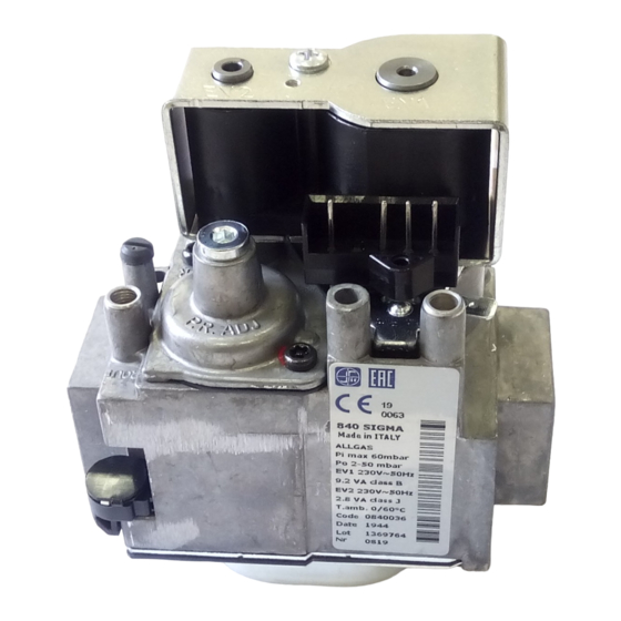
Газовый клапан Sit 840 SIGMA артикул: 8718585395-BB – функциональный прибор для комплектации систем управления подачи газа и безопасной эксплуатации газопотребляющего оборудования. Служит для оснащения атмосферных котлов. В единой конструкции совмещено два э/м запираемых клапана и встроенный регулятор давления.
Особенности
- Запорная арматура оснащена надежной, коррозиестойкой конструкцией, рассчитанной на работу при температуре воздуха от 0 до +60 градусов.
- Устройство содержит два автоматических э/м запорных клапана EV1 и EV2 (B и J) и регулятор давления.
- Клапан устанавливается в систему в любом положении. Соединение пилотной горелки – M10. В комплектацию входит две паронитовые прокладки Ø24/17,2х2 мм.
- Доступна настройка давления газа на выходе в пределах от 2 до 50 мбар и регулировка плавного розжига горелки.
- Клапан используется для систем, потребляющих газ семейства 1…3. Давление газа на входе – максимум 60 мбар.
Подробную информацию о газовой запорной арматуре можно узнать у наших специалистов.
![]()
Тел.: 8(495) 374 5170, WhatsApp, Telegram 8(985) 970 49 71 ![]()
Время работы: Ежедневно с 9.30 до 18.00
Электромагнитный клапан Sigma 840 предназначен для регулирования подачи газа в отопительном оборудовании бытового назначения следующих брендов:ACV, BAXI, BERETTA, BUDERUS, FERROLI, , PROTHERM, VAILLANT, VIESSMANN, WESTER. Конструктивно он представляет собой собственно клапан и управляющий орган – соленоид.
-

Газовый клапан SIT код 0.840.035 SigmaАртикул 0.840.035
Цена: 10910 ₽ -
Газовый клапан SIT код 0.840.036 SigmaАртикул 0.840.036
Цена: 13650 ₽ -
Газовый клапан 840 SIGMA код 0.840.038Артикул 0.840.038
Цена: 12850 ₽ -
Газовый клапан SIT Sigma 840 0.840.048Артикул 0.840.048
Цена: 14950 ₽ -
Газовый клапан 843 SIGMA код 0.843.003 Код Protherm KLO 0020025299Артикул 0.843.003
Цена: 11500 ₽ -
Газовый клапан 843 SIGMA код 0.843.005 Код Protherm KLO 0020025317Артикул 0.843.005
Цена: 13500 ₽ -
Газовый клапан 843 SIGMA код 0.843.018 Код Protherm KLO 0020027679Артикул 0.843.018
Цена: 12850 ₽ -
Газовый клапан SIT Sigma 840 0.840.042Артикул 0.840.042
Цена: 15680 ₽
Газовый клапан Sigma 840 имеет следующие преимущества перед другими типами газовой арматуры:
- небольшие габариты;
- малый период срабатывания.
Клапан Sit Sigma 840 выполняется в нормально-закрытом исполнении, то есть если на соленоид не поступает ток, это устройство полностью перекрывает поступление газа к бытовому котлу.