- Manuals
- Brands
- Nova Florida Manuals
- Boiler
- VELA COMPACT
- Installation use and care manual
-
Contents
-
Table of Contents
-
Troubleshooting
-
Bookmarks
Quick Links
VELA
CTN 24/RTN 24 CTFS 24/RTFS 24
CTFS 28/RTFS 28
COMPACT
INSTALLATION
USE AND MAINTENANCE
GB
IST 04 C 167 — 02
Related Manuals for Nova Florida VELA COMPACT
Summary of Contents for Nova Florida VELA COMPACT
-
Page 1
VELA CTN 24/RTN 24 CTFS 24/RTFS 24 CTFS 28/RTFS 28 COMPACT INSTALLATION USE AND MAINTENANCE IST 04 C 167 — 02… -
Page 2
Dear Customer, Thank you for choosing and buying one of our boilers. Please read these instructions carefully in order to install, operate, and maintain this equipment properly. -
Page 3: General Information For The Installer, Maintenance Technician And User
General information for fitters, maintenance technicians and users This INSTRUCTION MANUAL, which is an integral and indispensable part of the product, must be handed over to the user by the installer and must be kept in a safe place for future reference. The manual must accompany the boiler should it be sold or its pos- session transferred.
-
Page 4: Table Of Contents
CONTENTS General information for the Installer, Maintenance Technician and User Page 3 1. Instructions for the User Page 6 1.1 Control panel Page 6 1.2 Operating the boiler Page 7 1.2.1 Switching on Page 7 1.2.2 Operation Page 7 1…3 Boiler shut-down Page 8 1.3.1 Burner shut-down Page 8…
-
Page 5
PICTURE INDEX Pic. 1 – Control panel Page 6 Pic. 2 – Loading tap Page 8 Pic. 3 – CTN model dimensions Page 11 Pic. 4 – CTFS model dimensions Page 12 Pic. 5 – CTN model hydraulic layout Page 13 Pic. -
Page 6: Instructions For The User
1. INSTRUCTIONS FOR THE USER 1.1 CONTROL PANEL Pic. 1 – Control panel 1. Boiler working mode led (multi-color) 4. DHW selector and boiler shutdown reset See no. 1 chart at the bottom of the page for further details on The knob sets the boiler to stand-by ( position, fully turned coun- color displayed by led in relation to boiler working mode.
-
Page 7: Operating The Boiler
1.2 Operating the Boiler 1.2.1 Switching On The following procedures are to be implemented only after the boiler is installed, tested and its installation is certified by a qualified fitter. • Open the gas stop cock. • connect power mains to the boiler (no. 2 LED turns on displaying the green color); •…
-
Page 8: Boiler Shut-Down
1.3. Boiler shut-down When any malfunction occurs, the boiler automatically shuts down. Refer to no. 1 chart (on page 6) in order to detect the boiler operation status. In order to identify plausible malfunction origin, see no. 6 paragraph “Troubleshooting” at the end of the manual. In relation to the type of malfunction, proceed as described hereafter.
-
Page 9: Maintenance
1.4. Maintenance Have routine boiler maintenance performed according to the schedule indicated in the relevant section of this manual. Appropriate boiler maintenance ensures efficient operation, environment preservation, and safety for people, animals and objects. Only qualified personnel are to service the boiler. The manufacturer recommends Customers to contact authorized Service Centers for maintenance and repairs, they are best qualified for that procedure.
-
Page 10: Technical Characteristics And Dimensions
2. Technical Characteristics and Dimensions 2.1. Technical Characteristics The boiler is equipped with an integrated gas atmospheric burner and the following versions are available: — CTN 24 AF: open chamber, natural draught boiler with electronic ignition and instantaneous DHW supply; — CTFS 24 AF: sealed chamber, forced draught boiler with electronic ignition and instantaneous DHW supply;…
-
Page 11: Dimensions
2.2 Dimensions Model CTN top view bottom view G Gas inlet (1/2”) M CH flow (3/4”) C DHW flow (1/2”) F Cold water inlet (1/2”) R CH return (3/4”) Dimensions for connection to “plus” hydraulic kit (option) Dimensions for connection to base hydraulic kit (option) Pic.
-
Page 12: Pic. 4 — Ctfs Model Dimensions
Model CTFS top view bottom view G Gas inlet (1/2”) M CH flow (3/4”) C DHW flow (1/2”) F Cold water inlet (1/2”) R CH return (3/4”) Dimensions for connection to “plus” hydraulic kit (option) Dimensions for connection to base hydraulic kit (option) Pic.
-
Page 13: Hydraulic Layouts
2.3 Hydraulic layouts 1. DHW temperature probe 2. Modulating gas valve 3. CH temperature probe 4. Burner nozzles 5. Burner 6. Ignition/flame sensing electrode 7. Safety thermostat 8. Bi-thermal heat exchanger 9. Flue gas hood 10. Flue gas thermostat 11. Expansion vessel 12.
-
Page 14: Operating Data
2.4 Operating Data Below indicated burner pressures are to be checked after a three minute boiler operation. CTN 24 AF Gas mains inlet Max. heat Max. heat Min. heat Diameter of Function Burner pressure input output output nozzles pressure (mbar) (kW) (kW) (kW)
-
Page 15: General Characteristics
2.5 General Characteristics CTN 24 AF CTFS 24 AF Equipment category II2H3+ II2H3+ Number of burner nozzles installed n° Minimum CH flow rate Minimum CH pressure Maximum CH pressure Minimum DHW pressure Maximum CH pressure DHW specific capacity (∆t 30 °C) l/min 10.6 11.3…
-
Page 16: Instructions For The Installer
3. INSTRUCTIONS FOR THE INSTALLER 3.1 INSTALLATION STANDARDS The boiler is designed as II2H3+ category and is to be installed in compliance with laws and standards in force in the country of instal- lation. 3.2. Installation Installation and maintenance procedures are to be implemented employing exclusively accessories and spare parts which are approved and supplied by the manufacturer.
-
Page 17: Positioning The Boiler
3.2.3. Positioning the Boiler Each unit is supplied along with a paper template, in the package, allowing positioning the pipes connec- ting CH system, DHW system, gas supply, and air intake/flue gas discharge ducts to the boiler before installing the boiler itself. The template is made of highly resistant paper and is to be affixed to the wall on which the boiler is to be mounted using a carpenter’s level.
-
Page 18: Installing The Boiler
3.2.4. Installing the Boiler Before connecting the boiler to the CH and DHW pipe systems, clean the pipes carefully and eliminate any metal left during manufacturing and welding process, any oil or grease that may be left and that could damage the boiler or alter its operation if it reaches the boiler.
-
Page 19: Pic. 8 — Connection To Chimney System Of Ctn Model
Direct emission into the atmosphere Natural draught boilers can discharge flue gas directly into the atmosphere via a duct which goes through the outside walls of the buil- ding and ends with an anti-wind gust device terminal. The flue gas exhaust duct is to comply with the following requirements: — its sub-horizontal part inside the building must be as short as possible (not longer than 1,000 mm);…
-
Page 20: Forced Draught Boiler
3.2.6.2. Forced draught boiler 3.2.6.2.1 Configuration of air intake and flue gas discharge ducts Type Type B22 This boiler is conceived for connection Type to an existing flue system either internal or external to the boiler room. Combustion air is taken directly from the boiler room itself while flue gas is conveyed to the outside.
-
Page 21: Air Intake And Flue Gas Discharge System Via 100/60 Mm Coaxial Pipes
3.2.6.2.2. Air intake and flue gas discharge system via 100/60 mm coaxial pipes Type C12 Minimum permissible length of horizontal coaxial pipes is 1 meter, not counting the very first elbow connected to the boiler. Maximum permissible length of horizontal coaxial pipes is 4 meter, not counting the first elbow connected to the boiler. For each additional elbow maximum permissible length must be reduced by 1 meter.
-
Page 22: Air Intake And Flue Gas Discharge System Via 80/80 Mm Split Pipes
3.2.6.2.3 Air intake and flue gas discharge system via 80/80 mm split pipes C42 – C52 – C82 installation category Air intake Minimum permissible length of air intake pipe is 1 meter. Each wide radius 90° elbow (R=D) equals a 1 meter long pipe section. Each narrow radius 90°…
-
Page 23: Checking Combustion Efficiency
Example no. 2 Example no. 1 162 mm H min. = 150 mm 500 mm Pic. 14 – Split pipe installation samples Pic. 15 — Additional split pipe installation samples 3.2.7 Checking combustion efficiency In order to check combustion efficiency, turn no. 5 knob fully clockwise and completely open one or two domestic hot water taps so that the boiler will operate at max.
-
Page 24: Gas Mains Connection
3.2.8. Gas mains connection Cross-section of gas supply pipe must be equal or greater than the boiler one. Cross-section size depends on its length, layout pat- tern, gas flow rate. It is therefore to be sized accordingly. Comply with installation standards enforced in the installation country. They are considered as an integral part of this booklet. Remember that before operate an internal gas distribution system and before connecting it to a meter, it must be checked for leaks.
-
Page 25: Power Mains Connection
3.2.10. Power mains connections The boiler is supplied with a three-poled power cable, already connected to the electronic board and it is provided with an anti-ruptu- re firming clamp. The boiler is to be connected to a 230V-50Hz electric power supply. Comply with phase / neutral polarity sequence when power connecting the boiler.
-
Page 26: Starting The Boiler
3.4 Starting the Boiler 3.4.1 Preliminary Checks Before starting the boiler it is necessary to perform the following checks: — flue gas discharge pipe and its terminal are installed in accordance to the instructions: when the boiler is running no products generated by combustion are to leak from any gasket;…
-
Page 27: Pic. 18 — Electric Layout
Pic. 18 – Wiring diagram…
-
Page 28: No. 7 Chart — «Temperature — Nominal Resistance» Chart Of Temperature Probes
Relation between temperature (°C) and nominal resistance (Ohm) of CH probe SR and DHW probe SS. T (°C) 27203 24979 22959 21122 19451 17928 16539 15271 14113 13054 12084 11196 10382 9634 8948 8317 7736 7202 6709 6254 5835 5448 5090 4758 4452…
-
Page 29: Adaptation To Other Gas Types And Burner Adjustment
3.6 Adaptation to other gas types and burner adjustment The boilers are manufactured for the gas specified upon order. After sale transformation is to be exclusively implemented by qualified personnel, employing manufacturer designed accessories and following the procedure and adjustment instructions for an accurate boiler setting-up. Adapting the boiler from METHANE to LPG — Remove the main burner;…
-
Page 30: Testing The Boiler
B) Minimum heat output adjustment — Disconnect electric wiring from D modulation coil (pic. 20); — turn the burner on and check minimum pressure value according to no. 2 and no. 3 charts on page 14; — in order to adjust pressure, hold nut B still by means of a 100 mm tool, and turn plastic screw C CLOCKWISE to increase and COUNTER-CLOCKWISE to decrease gas pressure;…
-
Page 31: Maintenance
5. MAINTENANCE Routine boiler maintenance is to be scheduled according to current laws and regulations. Appropriate boiler maintenance ensures efficient operation, environment preservation, and safety for people, animals and objects. All maintenance and repair procedures are to be carried out by qualified personnel. The manufacturer recommends Customers to contact an authorized Service Centre for all maintenance and repair procedure as they are best trained for the purpose.
-
Page 32: Troubleshooting
6. TROUBLESHOOTING BOILER STATUS MALFUNCTION PROBABLE CAUSE SOLUTION Check gas pressure Gas supply failure Check gas network stopcock or gas network safety valve intervention Burner does not ignite Gas valve has disconnected Reconnect it Gas valve is faulty Replace it PCB is faulty Replace it Ignition/flame sensing electrode is…
-
Page 33
BOILER STATUS MALFUNCTION PROBABLE CAUSE SOLUTION No. 1 led is flashing green and red. DHW probe is disconnected Reconnect it The boiler will automatically resume operation as soon as the malfunc- DHW probe is not working tion is corrected. DHW probe is faulty Replace it Check DHW system System insufficient pressure or… -
Page 36
Fondital S.p.A. Via Mocenigo, 123 25078 VESTONE (Brescia) Italy Tel. +39 0365 878.31 — Fax +39 0365 596.257 e mail: info@fondital.it www.fondital.it The manufacturer reserves the right to implement any necessary and/or useful variation to products, without modifying fundamental characteristics.
Переналадка с природного газа на сжиженный
— Убедиться в том, что настенный котел отключен от электросети;
— снять главную горелку;
— снять форсунки с главной горелки и заменить их на форсунки нужного
диаметра в зависимости от типа нового газа.
— следует обязательно установить новые медные прокладки;
— установить на место главную горелку;
— на электронной плате котла перемычку MET-GPL установить в положение
GPL;
— отрегулировать газовый клапан.
Регулировка газового клапана siemens vgu56.a1109
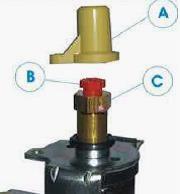
Рис.5. Регулировка газового клапана siemens
— Открутив маленькой отверткой защитный винт в штуцере измерения
входного давления газа, подсоединить к штуцеру микроманометр и проверить
давление газа на входе клапана (в газовой магистрали).
— Затем аналогичным образом подсоединить микроманометр к штуцеру
измерения давления газа на выходе клапана.
— Включить настенный котел Нова Флорида Вела Компакт на максимальную
тепловую мощность путем открытия большого водоразбора ГВС и установив
регулятор температуры ГВС на максимум.
— Сняв желтый пластмассовый защитный колпачок А, вращать винт С против
часовой стрелки для уменьшения давления и по часовой стрелке – для
увеличения давления.
— После настройки максимального давления снять разъем с бобины
модулятора, чтобы перевести котел на минимальную тепловую мощность.
— Отрегулировать минимальное давление внутренним винтом B газового
клапана (удерживая неподвижным внешний винт C).
— Надеть разъем на бобину модулятора и проверить правильность и
бесшумность розжига горелки;
— Проверить отсутствие утечек газа;
— Установить на место защитный пластмассовый колпачок А;
— По завершении вышеупомянутых операций заполнить бирку с указанием
установленных параметров и прикрепить ее к аппарату.
Проверка работоспособности температурных датчиков
Электроника проверяет правильность работы датчиков NTC, подключенных к
плате управления котла.
Если воспринимаемая датчиком температура выходит за пределы корректного
диапазона температур, фиксируемых датчиком, то это воспринимается как
нарушение работоспособности датчика.
— Нарушение работоспособности датчика температуры контура отопления в
режиме отопления или выполнения функции антизамораживания: горелка
немедленно выключается; насос останавливается после выполнения цикла
постциркуляции; вентилятор работает 1 минуту. Любые запросы на отопление
или выполнение функции антизамораживания игнорируются.
— Нарушение работоспособности датчика температуры контура отопления
когда настенный котел Нова Флорида Вела Компакт находится или в ждущем
режиме, или в летнем режиме, или в зимнем режиме, или при отсутствии
каких-либо запросов: котел выполняет функцию постциркуляции (1 секунда в
зимнем режиме, 30 секунд в летнем) и функцию поствентиляции на
протяжении 1 минуты.
— Нарушение работоспособности датчика температуры контура отопления в
режиме ГВС: о нарушении только сигнализируется, но ГВС продолжает
обеспечиваться.
— Нарушение работоспособности датчика температуры контура ГВС при
выполнении запроса на ГВС: горелка немедленно выключается; насос
выполняет
постциркуляцию 1 секунду в летнем и 30 секунд в зимнем режимах.
— Вентилятор работает 1 минуту (продолжительность функции поствентиляции
после блокировки или нарушения работоспособности температурного
датчика). Любые запросы на ГВС игнорируются, в то время как функции
отопления и антизамораживания действуют.
Общая проверка модулятора газового клапана
Электроника проверяет работоспособность пропорционального модулятора
газового клапана.
Нарушение работоспособности фиксируется в том случае, если модулятор
электрически отсоединен или имеет короткое замыкание.
В случае нарушения работоспособности модулятора все функции котла
сохраняются, но на минимальной тепловой мощности.
Сигнал о нарушении работоспособности модулятора исчезает, когда
электрические параметры модулятора возвращаются в стандартные пределы.
Автоматическая проверка наличия пламени
Устройство определения наличия пламени всегда активно и непрерывно
контролирует наличие пламени.
При поступлении запроса на включение котла проверяется состояние
контактов дифференциального реле давления воздуха (модель CTFS 24 AF) и
включается вентилятор.
Когда исходное состояние контактов дифференциального реле давления
воздуха (котел Nova Florida Vela Compact CTFS 24 AF) или термостата
дымовых
газов (модель CTFN 24) правильное, устройство выдерживает задержку TW
(1,5 секунды), после чего включает газовый клапан и трансформатор
зажигания.
Если зафиксировано наличие пламени, газовый клапан остается открытым.
Развитие розжига
После задержки инициализируется розжиг горелки. Ток в катушке модулятора
нарастает в течение 10 секунд: от значения, соответствующего
минимальному давлению газа, до 65% максимального значения для аппарата с
открытой камерой сгорания и 80% максимума для турбокотла).
Собственно, процедура розжига завершается через 1 секунду после того,
как определено наличие пламени.
Теперь, только в аппаратах с закрытой камерой сгорания, продолжается
процесс развития пламени, который состоит в том, что на модулятор в
течение
двух секунд подается возрастающий до максимума ток.
После полного развития пламени газовый котел Нова Флорида Вела Компакт
начинает работу в нормальном режиме. Трансформатор зажигания
выключается через 2 секунды после определения наличия пламени или по
окончании периода безопасного розжига.
Если в холодных условиях при попытке розжига пламя не возникает,
автоматически осуществляются повторные попытки розжига (до 5 попыток для
турбокотла и 2 попытки для дымоходного).
Между попытками розжига осуществляется проветривание камеры сгорания (10
секунд для турбокотла и 35 секунд для дымоходного).
Если пламя исчезает, устройство определения наличия пламени осуществляет
повторную попытку розжига.
Устройство определения наличия пламени переходит в состояние блокировки,
когда при последней попытке розжига пламя не обнаружено в течение
периода безопасного розжига TS (10 секунд) или, если при выключенном
газовом клапане более чем 1 минуту фиксируется наличие постороннего
пламени.
Для разблокировки необходимо подождать несколько секунд, повернуть
соответствующий регулятор в положение разблокировки, выждать некоторое
время и вернуть регулятор в нужное положение.
Термостат дымовых газов (только котел Nova Florida Vela Compact CTN 24
AF)
Контакты термостат дымовых газов являются нормально замкнутыми. Когда
выход дымовых газов затруднен, то дым начинает обтекать
дымоулавливатель с внешней стороны и температура дымоулавливателя (на
котором установлен термостат) повышается, в результате чего триггеры
термостата размыкают контакты последнего.
При размыкании контактов газовый клапан обесточивается и через 2 секунды
после размыкания контактов электронная плата блокируется (если в
течение 2 секунд контакты термостата замкнутся, то электронная плата
продолжит нормальное функционирование).
После блокировки насос выполняет постциркуляцию. Если в течение 10
секунд после блокировки контакты термостат замкнутся, то котел Нова
Флорида
Вела Компакт может рестартовать.
Десятиминутный период ожидания можно обнулить путем разблокировки
аппарата с помощью регулятора ГВС.
Начало розжига: если в течение 2 секунд после начала розжига контакты
термостата дымовых газов разомкнутся, то плата блокируется и выполняется
операция постциркуляции насоса.
По истечении 10 минут блокировки в результате размыкания контактов
термостата дымовых газов (период ожидания для термостата дымовых газов)
плата может автоматически рестартовать, если контакты термостата дымовых
газов будут замкнуты.
Десятиминутный период ожидания можно обнулить путем разблокировки котла
с помощью регулятора ГВС.
Для разблокировки необходимо подождать около 5 секунд, повернуть
соответствующий регулятор в положение разблокировки, выждать некоторое
время
и вернуть регулятор в нужное положение.
Дифференциальное реле давления воздуха (только модель котла Nova Florida
Vela Compact CTFS 24)
Дифреле давления воздуха подключено непосредственно к электронной плате
и его контакты являются нормально разомкнутыми. До включения
вентилятора контакты дифреле давления воздуха находятся в состоянии н.р.
(нормально разомкнутые), а после включения вентилятора замыкаются.
При разомкнутых контактах дифреле давления воздуха газовый клапан
включиться не может.
Если через 10 секунд после включения вытяжного вентилятора контакты
дифреле давления воздуха все еще разомкнуты, то вырабатывается сигнал
блокировки, который не требует выполнения процедуры разблокировки.
Такой же сигнал блокировки, не требующий выполнения процедуры
разблокировки, вырабатывается и в том случае, если контакты дифреле
давления
воздуха в режиме ожидания или при работе котла находятся в неправильном
положении.
Если контакты дифреле давления воздуха находятся в неправильном
положении более 1 минуты, то котел переходит в состояние перманентной
блокировки, выход из которого требует осуществления процедуры
разблокировки.
Давление дифференциального реле: 45/35 Па Pmax=1500 Па
Термостат безопасности
Термостат безопасности размещен на битермическом теплообменнике и его
контакты являются нормально замкнутыми.
Когда фиксируется температура выше 95°C, контакты размыкаются, тем самым
прерывая электропитание газового клапана и выключая горелку.
Срабатывание термостата безопасности при работающем газовом клапане
приводит к блокировке котла.
Срабатывание термостата безопасности при неработающем газовом клапане (в
период между запросами или когда котел находится в ждущем режиме)
приводит к появлению сигнала о нарушении работоспособности (светодиод 2
горит красным).
Эта ситуация не требует процедуры разблокировки. Включение горелки будет
отложено до тех пор, пока контакты термостата безопасности не замкнутся.
Термостат безопасности с нормально замкнутыми контактами коммутирует
напряжение 20Vdc.
Температура срабатывания 95°C.
Температурный датчик контура отопления: NTC 10k Ohm при 25°C.
Температурный датчик контура ГВС: NTC 10k Ohm при 25°C.
1.1 CONTROL PANEL
1
2
3
Pic. 1 – Control panel
1. Boiler working mode led (multi-color)
See no. 1 chart at the bottom of the page for further details on
color displayed by led in relation to boiler working mode.
2. Boiler working mode led (multi-color)
See no. 1 chart at the bottom of the page for further details on
color displayed by led in relation to boiler working mode.
3. Water pressure gauge
The gauge shows water pressure in the CH system.
4. CH selector and adjusting knob
The knob activates or de-activates CH operation, and adjusts CH
water temperature between a minimum of 35°C and a maximum
of 78°C.
When the knob is set to
boiler is set to summer mode and CH operation is de-activated.
Power connected to boiler
Flame presence
Active CH mode
Shutdown due to flame absence
Flue gas thermostat shutdown (CTN)
Air/flue gas pressure switch shutdown (CTFS)
Safety thermostat shutdown
Safety thermostat shutdown
Gas valve alarm
Water pressure switch alarm (>85°)
CH flow probe alarm
DHW flow probe alarm
No. 1 Chart – Color displayed by led in relation to boiler operation status
KEY CHART TO ACHRONYMS
OFF
LED off
RED
LED on, displaying the color stated in the chart
FLASHING RED
LED flashing, displaying the color stated in the chart
RED/GREEN LED flashing, displaying in sequence the colors stated in the chart
n/a
LED status is not relevant
6
(fully turned counter-clockwise), the
4. DHW selector and boiler shutdown reset
The knob sets the boiler to stand-by (
ter-clockwise), and adjust DHW temperature between a minimum
of 35°C and a maximum of 58°C.
When the boiler has shut down is to be reset by turning the knob
to
position.
WARNING
The boiler has a special built-in regulator limiting DHW flow up to
10 liter per minute. In addition to the setting of no. 5 selector,
the temperature of the DHW supplied also depends on the flow
requested by the user and the temperature of the water mains
supply.
LED 1
n/a
n/a
GREEN
OFF
YELLOW
RED
FLASHING GREEN
FLASHING YELLOW
FLASHING RED
FLASHING YELLOW/RED
FLASHING GREEN/RED
4
5
position, fully turned coun-
LED 2
GREEN
YELLOW
n/a
RED
OFF
OFF
OFF
OFF
n/a
OFF
OFF