Материнская плата B550 AORUS ELITE AX V2

Информация о продукте — B550 AORUS ELITE AX V2 и B550 AORUS ELITE V2
B550 AORUS ELITE AX V2 и B550 AORUS ELITE V2 — материнские платы производства GIGABYTE. Эти материнские платы поддерживают AMD Socket AM4 и совместимы с процессорами AMD RyzenTM 5000 G-Series.
Процессоры, процессоры AMD RyzenTM серии 5000, процессоры AMD RyzenTM серии 4000 G и процессоры AMD RyzenTM серии 3000. Материнские платы оснащены чипсетом AMD B550 и имеют четыре разъема DDR4 DIMM, которые могут поддерживать до 128 ГБ системной памяти. Они имеют двухканальную архитектуру памяти и поддерживают модули памяти DIMM без буферизации ECC 1Rx8/2Rx8, модули памяти DIMM без буферизации ECC 1Rx8/2Rx8/1Rx16 и модули памяти Extreme Memory Pro.file (XMP) модули памяти.
Материнские платы имеют несколько портов и разъемов, включая USB20, SYS_FAN1, ATX_12V, M2_WIFI (примечание), DP_HDMI, QFLED, QFLASH_PLUS, U32, U32G2, U32_LAN, CPU_FAN, CPU_OPT, D_LED2, LED_C2, ATX Socket AM4, DDR4_A1, DDR4_A2, DDR4_B1, D DR4_B2 , SATA3 1 0, LED_CPU, SYS_FAN2, M2A_CPU, AUDIO, M_BIOS, CODEC, PCIEX2, BAT, M2B_SB, PCIEX1_1, PCIEX1_2, F_AUDIO, LED_C1, концентратор USB 2.0, CLR_CMOS, TPM, F_USB1, SYS_FAN3, F_USB2, F_U32, F_U 32С, и F_ПАНЕЛЬ.
Инструкции по использованию продукта
Перед использованием материнской платы внимательно прочитайте руководство пользователя и соблюдайте меры предосторожности при установке, чтобы не повредить чувствительные электронные схемы и компоненты. Руководство пользователя также содержит подробную информацию о компоновке материнской платы, настройке BIOS, установке операционной системы и драйверов и определении номера версии материнской платы.
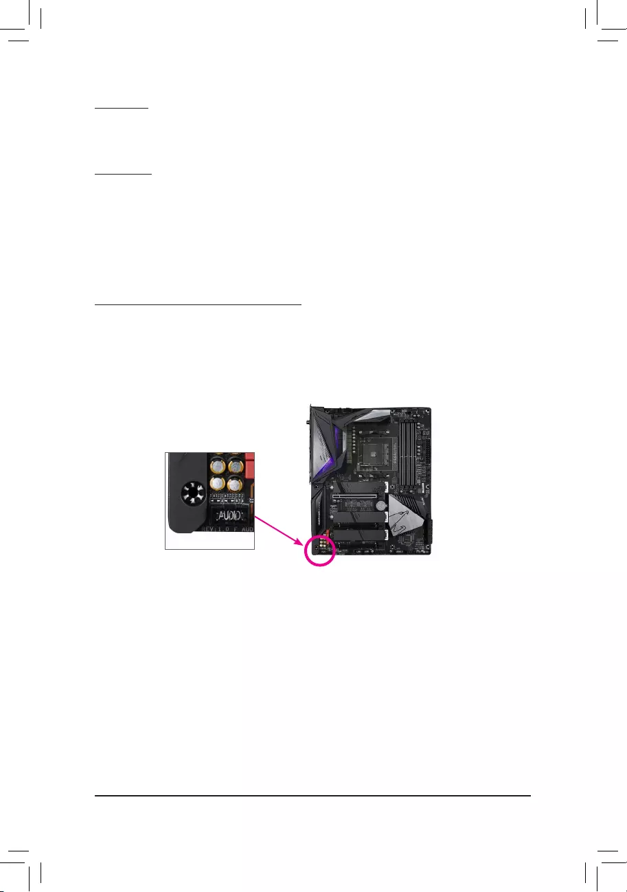
Чтобы использовать материнскую плату, сначала определите номер версии вашей материнской платы, проверив этикетку, которая выглядит следующим образом: REV: XX Эта информация важна при обновлении BIOS материнской платы, драйверах или поиске технической информации.
Подключите необходимые компоненты к соответствующим портам и разъемам на материнской плате. Установите ЦП, модули памяти и другие компоненты в соответствии с инструкциями производителя. Обратитесь к руководству пользователя для получения дополнительной информации о процедурах установки.
После установки всех компонентов включите систему и следуйте инструкциям на экране, чтобы завершить процесс установки операционной системы и драйверов. Для быстрой настройки продукта обратитесь к Руководству по быстрой установке на веб-сайте GIGABYTE. webсайт.
Если у вас возникнут какие-либо проблемы с продуктом, обратитесь к разделу устранения неполадок в руководстве пользователя или обратитесь за помощью в службу поддержки GIGABYTE.
Авторские права
© 2023 GIGA-BYTE TECHNOLOGY CO., LTD. Все права защищены.
Торговые марки, упомянутые в этом руководстве, зарегистрированы на своих законных владельцев.
Отказ от ответственности
Информация в этом руководстве защищена законами об авторских правах и является собственностью GIGABYTE. Компания GIGABYTE может вносить изменения в характеристики и функции, указанные в данном руководстве, без предварительного уведомления. Никакая часть данного руководства не может быть воспроизведена, скопирована, переведена, передана или опубликована в любой форме и любыми средствами без предварительного письменного разрешения компании GIGABYTE.
- Для получения подробной информации о продукте внимательно прочитайте Руководство пользователя.
- Для быстрой настройки продукта обратитесь к Руководству по быстрой установке на веб-сайте GIGABYTE. webсайт. https://download.gigabyte.com/FileList/Manual/mb_manual_installation-guide_103.pdf?m=sw
Информацию о продукте можно найти на нашем webсайт по адресу: https://www.gigabyte.com
Определение версии вашей материнской платы
Номер ревизии на вашей материнской плате выглядит так: «REV: XX».ample, «REV: 1.0» означает версию материнской платы 1.0. Проверьте версию материнской платы перед обновлением BIOS материнской платы, драйверов или при поиске технической информации.
Exampль:

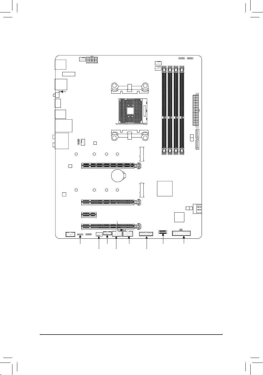
Внедрение продукции
Макет материнской платы

Установка оборудования
Меры предосторожности при установке
Материнская плата содержит множество чувствительных электронных схем и компонентов, которые могут быть повреждены в результате электростатического разряда (ЭСР). Перед установкой внимательно прочитайте руководство пользователя и выполните следующие действия:
- Перед установкой убедитесь, что корпус подходит для материнской платы.
- Перед установкой не удаляйте и не ломайте наклейку с серийным номером материнской платы или гарантийную наклейку, предоставленную вашим дилером. Эти наклейки необходимы для подтверждения гарантии.
- Всегда отключайте питание переменного тока, вынимая шнур питания из розетки перед установкой или извлечением материнской платы или других компонентов оборудования.
- При подключении аппаратных компонентов к внутренним разъемам на материнской плате убедитесь, что они подключены плотно и надежно.
- При обращении с материнской платой не прикасайтесь к металлическим выводам или разъемам.
- При работе с электронными компонентами, такими как материнская плата, ЦП или память, лучше всего надевать антистатический браслет. Если у вас нет антистатического браслета, держите руки сухими и сначала прикоснитесь к металлическому предмету, чтобы снять статическое электричество.
- Перед установкой материнской платы положите ее на антистатическую прокладку или в контейнер с защитой от электростатического заряда.
- Перед подключением или отключением кабеля питания от материнской платы убедитесь, что питание отключено.
- Перед включением питания убедитесь, что напряжение питанияtage был установлен в соответствии с местным voltagе стандарт.
- Перед использованием изделия убедитесь, что все кабели и разъемы питания аппаратных компонентов подключены.
- Во избежание повреждения материнской платы не допускайте контакта винтов со схемой материнской платы или ее компонентами.
- Убедитесь, что на материнской плате или внутри корпуса компьютера нет оставшихся винтов или металлических компонентов.
- Не ставьте компьютерную систему на неровную поверхность.
- Не размещайте компьютерную систему в местах с высокой температурой или во влажной среде.
- Включение питания компьютера в процессе установки может привести к повреждению компонентов системы, а также нанести физический вред пользователю.
- Если вы не уверены в каких-либо этапах установки или у вас возникли проблемы, связанные с использованием продукта, обратитесь к сертифицированному специалисту по компьютерам.
- Если вы используете адаптер, удлинительный кабель питания или удлинитель, обязательно ознакомьтесь с инструкциями по их установке и/или заземлению.
Технические характеристики изделия
| ЦП |
(Перейдите на сайт GIGABYTE webсайт для последнего списка поддержки ЦП.) |
| Набор микросхем | AMD B550 |
| Память |
(Перейдите на сайт GIGABYTE webсайт для последних поддерживаемых скоростей памяти и модулей памяти.) |
| На борту Graphics |
|
| Аудио |
|
| ЛВС | Чип Realtek® 2.5GbE LAN (2.5 Гбит/1 Гбит/100 Мбит) |
| Модуль беспроводной связи (Примечание) |
|
| Слоты расширения |
|
| Интерфейс хранения |
|
| USB |
|
| Внутренние разъемы |
|
| Внутренние разъемы |
|
| Разъемы задней панели |
|
| Контроллер ввода / вывода | Микросхема контроллера ввода/вывода iTE® |
| Монитор оборудования |
* Поддержка функции управления скоростью вентилятора зависит от установленного вентилятора. |
| BIOS |
|
| Отличительные особенности |
|
| Программное обеспечение в комплекте |
|
| Operating System |
|
| Форм-фактор | Форм-фактор ATX; 30.5 см х 24.4 см |
* GIGABYTE оставляет за собой право вносить любые изменения в технические характеристики продукта и информацию, относящуюся к продукту, без предварительного уведомления.
- Пожалуйста, посетите сайт GIGABYTE webсайт для поддержки списков ЦП, модулей памяти, твердотельных накопителей и устройств M.2.
https://www.gigabyte.com/Motherboard/B550-AORUS-ELITE-AX-V2-rev-15?m=dl#support-dl https://www.gigabyte.com/Motherboard/B550-AORUS-ELITE-V2-rev-15?m=dl#support-dl - Пожалуйста, посетите страницу SERVICE/SUPPORTUtility на сайте GIGABYTE. webсайт для загрузки последней версии приложений.
https://www.gigabyte.com/Support/Utility/Motherboard?m=ut
Установка ЦП
Прежде чем приступить к установке ЦП, прочтите следующие рекомендации:
- Убедитесь, что материнская плата поддерживает ЦП.
(Перейдите на сайт GIGABYTE webсайт для последнего списка поддержки ЦП.) - Всегда выключайте компьютер и отсоединяйте кабель питания от розетки перед установкой ЦП, чтобы предотвратить повреждение оборудования.
- Найдите контакт один из ЦП. CPU не может быть вставлен, если он неправильно ориентирован.
- Нанесите ровный и тонкий слой термопасты на поверхность процессора.
- Не включайте компьютер, если процессорный кулер не установлен, иначе может произойти перегрев и повреждение процессора.
- Установите частоту хоста ЦП в соответствии со спецификациями ЦП. Не рекомендуется устанавливать частоту системной шины выше технических характеристик оборудования, поскольку она не соответствует стандартным требованиям к периферийным устройствам. Если вы хотите установить частоту, превышающую стандартные характеристики, сделайте это в соответствии с техническими характеристиками вашего оборудования, включая процессор, видеокарту, память, жесткий диск и т. д.
Установка ЦП
Полностью поднимите фиксирующий рычаг сокета ЦП. Найдите контакт один (обозначенный маленьким треугольником) разъема ЦП и ЦП. Как только ЦП вставлен в гнездо, поместите один палец на середину ЦП, опустив фиксирующий рычаг и зафиксировав его в полностью заблокированном положении.
 Не вставляйте ЦП в сокет ЦП силой, пока не будет поднят фиксирующий рычаг сокета ЦП, иначе может произойти повреждение ЦП и сокета ЦП.
Установка памяти
Прежде чем приступить к установке модуля памяти, прочтите следующие рекомендации:
- Убедитесь, что материнская плата поддерживает память. Рекомендуется использовать память той же емкости, марки, скорости и микросхем.
(Перейдите на сайт GIGABYTE webсайт для последних поддерживаемых скоростей памяти и модулей памяти.) - Всегда выключайте компьютер и отсоединяйте шнур питания от розетки перед установкой модуля памяти, чтобы предотвратить повреждение оборудования.
- Модули памяти имеют надежную конструкцию. Модуль памяти можно установить только в одном направлении. Если вы не можете вставить память, измените направление.
Конфигурация двухканальной памяти
Эта материнская плата имеет четыре разъема для памяти и поддерживает двухканальную технологию. После установки памяти BIOS автоматически определит характеристики и емкость памяти. Включение двухканального режима памяти удвоит исходную пропускную способность памяти.
& Пожалуйста, посетите GIGABYTE webсайт для получения подробной информации об установке оборудования.
http://www.gigabyte.com/WebPage/210/quick-guide.html?m=sw
Четыре разъема памяти разделены на два канала, и каждый канал имеет два разъема памяти следующим образом:
- Канал А: DDR4_A1, DDR4_A2
- Канал B: DDR4_B1, DDR4_B2
- Рекомендуемая двухканальная конфигурация памяти:

(SS=Односторонний, DS=Двусторонний, «- -»=Без памяти)
Из-за ограничений процессора прочитайте следующие рекомендации перед установкой памяти в двухканальном режиме.
- Двухканальный режим нельзя включить, если установлен только один модуль памяти.
- При включении двухканального режима с двумя или четырьмя модулями памяти рекомендуется использовать память одинаковой емкости, марки, скорости и микросхем.
Установка карты расширения
Прежде чем приступить к установке платы расширения, прочтите следующие рекомендации:
- Убедитесь, что материнская плата поддерживает карту расширения. Внимательно прочтите руководство, прилагаемое к плате расширения.
- Всегда выключайте компьютер и отсоединяйте кабель питания от розетки перед установкой платы расширения, чтобы предотвратить повреждение оборудования.
Разъемы задней панели
 Порт USB 2.0 / 1.1
Порт USB поддерживает спецификацию USB 2.0/1.1. Используйте этот порт для USB-устройств.
Антенные разъемы SMA (2T2R) (Примечание 1)
Используйте этот разъем для подключения антенны.
Подсоедините антенны к антенным разъемам, а затем правильно направьте антенны для лучшего приема сигнала. DisplayPort
(Примечание 2)
DisplayPort обеспечивает высококачественное цифровое изображение и звук, поддерживая двунаправленную передачу звука. DisplayPort может поддерживать механизмы защиты контента как DPCP, так и HDCP 2.3. Он обеспечивает улучшенные визуальные эффекты, поддерживающие Rec. 2020 (широкая цветовая гамма) и расширенный динамический диапазон (HDR) для воспроизведения Blu-ray UHD. Вы можете использовать этот порт для подключения монитора с поддержкой DisplayPort.
Примечание: Технология DisplayPort может поддерживать максимальное разрешение 5120×2880 при 60 Гц, но фактическое поддерживаемое разрешение зависит от используемого монитора.
Порт HDMI (Примечание 2)
Порт HDMI совместим с HDCP 2.3 и поддерживает форматы Dolby TrueHD и DTS HD Master Audio. Он также поддерживает 192-канальный аудиовыход LPCM до 24 кГц/7.1 бит. Вы можете использовать этот порт для подключения монитора с поддержкой HDMI. Максимальное поддерживаемое разрешение — 4096×2160 при 60 Гц, но фактические поддерживаемые разрешения зависят от используемого монитора.
После установки устройства DisplayPort/HDMI обязательно установите устройство воспроизведения звука по умолчанию на DisplayPort/HDMI. (Название элемента может отличаться в зависимости от вашей операционной системы.)
- Кнопка Q-Flash Plus (Примечание 3)
Q-Flash Plus позволяет обновлять BIOS, когда ваша система выключена (состояние отключения S5). Сохраните последнюю версию BIOS на флэш-накопителе USB и подключите его к порту Q-Flash Plus, после чего вы сможете автоматически обновить BIOS, просто нажав кнопку Q-Flash Plus. Индикатор QFLED будет мигать, когда начнутся действия по сопоставлению и перепрошивке BIOS, и перестанет мигать, когда перепрошивка BIOS будет завершена. - Порт USB 3.2 Gen 1 (порт Q-Flash Plus)
Порт USB 3.2 Gen 1 поддерживает спецификацию USB 3.2 Gen 1 и совместим со спецификацией USB 2.0. Используйте этот порт для USB-устройств. Перед использованием Q-Flash Plus (Примечание 3) обязательно сначала вставьте флэш-накопитель USB в этот порт. - Порт USB 3.2 Gen 2 Type-A (красный)
Порт USB 3.2 Gen 2 Type-A поддерживает спецификацию USB 3.2 Gen 2 и совместим со спецификацией USB 3.2 Gen 1 и USB 2.0. Используйте этот порт для USB-устройств. - Порт LAN RJ-45
Порт Gigabit Ethernet LAN обеспечивает подключение к Интернету со скоростью передачи данных до 2.5 Гбит / с. Ниже описаны состояния индикаторов порта LAN.

- Порт USB 3.2 Gen 1
Порт USB 3.2 Gen 1 поддерживает спецификацию USB 3.2 Gen 1 и совместим со спецификацией USB 2.0. - Выход на центральный динамик / сабвуфер
Используйте этот аудиоразъем для подключения центрального динамика/сабвуфера. - Выход на задний динамик
Используйте этот аудиоразъем для подключения тыловых динамиков. - Оптический выходной разъем S/PDIF
Этот разъем обеспечивает вывод цифрового звука на внешнюю аудиосистему, поддерживающую цифровой оптический звук. Перед использованием этой функции убедитесь, что ваша аудиосистема оснащена оптическим разъемом цифрового аудиовхода. - Линейный вход/выход на боковой динамик
Линия в гнезде. Используйте этот аудиоразъем для линейного подключения таких устройств, как оптический привод, плеер и т. д. - Линейный выход / выход на передние динамики
Гнездо линейного выхода. - Вход микрофона/выход бокового динамика
Микрофон в гнезде.
(Примечание 1) Только для B550 AORUS ELITE AX V2.
(Примечание 2) Только для процессоров AMD Ryzen™ серии 5000 G/4000 G.
(Примечание 3) Чтобы включить функцию Q-Flash Plus, посетите раздел «Уникальные возможности». webстраница GIGABYTE webсайт.
Конфигурации аудиоразъема:
| разъем | Наушники / 2 канала | 4-канал | 5.1-канал | 7.1-канал |
| Выход на центральный динамик / сабвуфер | ||||
| Выход на задний динамик | ||||
| Линейный вход/выход на боковой динамик | ||||
| Линейный выход / выход на передние динамики | ||||
| Вход микрофона/выход бокового динамика |
Если вы хотите установить боковой динамик, вам необходимо переназначить разъем линейного входа или микрофонного входа, чтобы он был выходом бокового динамика через аудиодрайвер. & Пожалуйста, посетите GIGABYTE webсайт для получения подробной информации о настройке аудио программного обеспечения. https://www.gigabyte.com/WebPage/697/realtek897-audio.html
- При отсоединении кабеля, подключенного к разъему на задней панели, сначала отсоедините кабель от устройства, а затем отсоедините его от материнской платы.
- При отсоединении кабеля вытягивайте его прямо из разъема. Не раскачивайте его из стороны в сторону во избежание короткого замыкания внутри кабельного разъема.
Внутренние разъемы

| 1) ATX_12V | 10) M2A_ЦП/M2B_SB |
| 2) АТХ | 11) F_ПАНЕЛЬ |
| 3) ЦП_ВЕНТИЛЯТОР | 12) Ф_АУДИО |
| 4) SYS_FAN1/2/3 | 13) Ф_У32С |
| 5) ЦП_ОПТ | 14) Ф_У32 |
| 6) LED_ЦП | 15) Ф_УСБ1/Ф_УСБ2 |
| 7) D_LED1/D_LED2 | 16) ТПМ |
 LED_C1/LED_C2 LED_C1/LED_C2 |
17) CLR_CMOS |
Перед подключением внешних устройств прочтите следующие рекомендации:
- Сначала убедитесь, что ваши устройства совместимы с разъемами, которые вы хотите подключить.
- Перед установкой устройств обязательно выключите устройства и компьютер. Отсоедините шнур питания от розетки, чтобы не повредить устройства.
- После установки устройства и перед включением компьютера убедитесь, что кабель устройства надежно подключен к разъему на материнской плате.
ATX_12V/ATX (2×4 разъема питания 12 В и 2×12 разъема основного питания)
С помощью разъема питания блок питания может обеспечить достаточно стабильное питание для всех компонентов на материнской плате. Перед подключением разъема питания сначала убедитесь, что питание отключено и все устройства правильно установлены. Разъем питания имеет надежную конструкцию. Подсоедините кабель питания к разъему питания, соблюдая правильную ориентацию.
Разъем питания 12 В в основном подает питание на процессор. Если разъем питания 12 В не подключен, компьютер не запустится.
Для удовлетворения требований расширения рекомендуется использовать источник питания, способный выдерживать высокое энергопотребление (500 Вт или выше). Если используется блок питания, который не обеспечивает требуемой мощности, это может привести к нестабильной работе или невозможности загрузки системы.
| Номер контакта | Определение | Номер контакта | Определение |
| 1 | GND (только для 2×4-контактных 12 В) | 5 | +12 В (только для 2×4-контактного 12 В) |
| 2 | GND (только для 2×4-контактных 12 В) | 6 | +12 В (только для 2×4-контактного 12 В) |
| 3 | GND | 7 | + 12V |
| 4 | GND | 8 | + 12V |

| Номер контакта | Определение | Номер контакта | Определение |
| 1 | 3.3V | 13 | 3.3V |
| 2 | 3.3V | 14 | -12V |
| 3 | GND | 15 | GND |
| 4 | + 5V | 16 | PS_ON (мягкое включение/выключение) |
| 5 | GND | 17 | GND |
| 6 | + 5V | 18 | GND |
| 7 | GND | 19 | GND |
| 8 | Мощность Хорошая | 20 | NC |
| 9 | 5VSB (в режиме ожидания +5В) | 21 | + 5V |
| 10 | + 12V | 22 | + 5V |
| 11 | +12 В (только для 2×12-контактных разъемов ATX) | 23 | +5 В (только для 2×12-контактных разъемов ATX) |
| 12 | 3.3 В (только для 2×12-контактных разъемов ATX) | 24 | GND (только для 2×12-контактных разъемов ATX) |
CPU_FAN/SYS_FAN1/2/3 (заголовки вентилятора)
Все коннекторы вентиляторов на этой материнской плате 4-контактные. Большинство коллекторов вентиляторов имеют надежную конструкцию вставки. При подключении кабеля вентилятора убедитесь, что он подключен правильно (черный провод разъема является проводом заземления). Функция управления скоростью требует использования вентилятора с конструкцией управления скоростью вращения вентилятора. Для оптимального отвода тепла рекомендуется установить внутри корпуса системный вентилятор.

| Номер контакта | Определение |
| 1 | GND |
| 2 | Voltage Регулятор скорости |
| 3 | Смысл |
| 4 | ШИМ-управление скоростью |
- Обязательно подключите кабели вентилятора к разъемам вентилятора, чтобы предотвратить перегрев процессора и системы. Перегрев может привести к повреждению процессора или зависанию системы.
- Эти разъемы для вентиляторов не являются блоками перемычек конфигурации. Не устанавливайте перемычку на разъемы.
CPU_OPT (разъем вентилятора ЦП с водяным охлаждением)
Разъем вентилятора 4-контактный и имеет надежную конструкцию вставки. Большинство коллекторов вентиляторов имеют надежную конструкцию вставки. При подключении кабеля вентилятора убедитесь, что он подключен правильно (черный провод разъема является проводом заземления). Функция управления скоростью требует использования вентилятора с конструкцией управления скоростью вращения вентилятора. 
| Номер контакта | Определение |
| 1 | GND |
| 2 | Voltage Регулятор скорости |
| 3 | Смысл |
| 4 | ШИМ-управление скоростью |
- Обязательно подключите кабели вентилятора к разъемам вентилятора, чтобы предотвратить перегрев процессора и системы. Перегрев может привести к повреждению процессора или зависанию системы.
- Эти разъемы для вентиляторов не являются блоками перемычек конфигурации. Не устанавливайте перемычку на разъемы.
| Номер контакта | Определение |
| 1 | 12V |
| 2 | G |
| 3 | R |
| 4 | B |
Подключите светодиодную ленту процессорного кулера/светодиодную ленту RGB к разъему. Контакт питания (отмечен треугольником на вилке) светодиодной ленты должен быть подключен к контакту 1 (12 В) этого разъема. Неправильное подключение может привести к повреждению светодиодной ленты.
D_LED1/D_LED2 (адресные заголовки светодиодных лент)
Заголовки можно использовать для подключения стандартной адресуемой светодиодной ленты 5050 с максимальной номинальной мощностью 5 А (5 В) и максимальным количеством светодиодов 1000.

| Номер контакта | Определение |
| 1 | GND |
| 2 | TXP |
| 3 | TXN |
| 4 | GND |
| 5 | RXN |
| 6 | RXP |
| 7 | GND |
Подключите адресную светодиодную ленту к разъему. Контакт питания (отмечен треугольником на вилке) светодиодной ленты должен быть подключен к контакту 1 адресного разъема светодиодной ленты. Неправильное подключение может привести к повреждению светодиодной ленты.
Чтобы узнать, как включить/выключить свет светодиодной ленты, посетите раздел «Уникальные возможности». webстраница GIGABYTE webсайт.
Перед установкой устройств обязательно выключите устройства и компьютер. Отсоедините шнур питания от розетки, чтобы не повредить устройства.
LED_C1/LED_C2 (разъемы для светодиодных лент RGB)
Заголовки можно использовать для подключения стандартной светодиодной ленты 5050 RGB (12 В / G / R / B) с максимальной номинальной мощностью 2 А (12 В) и максимальной длиной 2 м.

| Номер контакта | Определение |
| 1 | 12V |
| 2 | G |
| 3 | R |
| 4 | B |
Подключите светодиодную ленту RGB к разъему. Контакт питания (отмечен треугольником на вилке) светодиодной ленты должен быть подключен к контакту 1 (12 В) этого разъема. Неправильное подключение может привести к повреждению светодиодной ленты.
Чтобы узнать, как включить/выключить свет светодиодной ленты, посетите раздел «Уникальные возможности». webстраница GIGABYTE webсайт.
Перед установкой устройств обязательно выключите устройства и компьютер. Отсоедините шнур питания от розетки, чтобы не повредить устройства.
SATA3 0/1/2/3 (разъемы SATA 6 Гбит/с)
Разъемы SATA соответствуют стандарту SATA 6 Гбит/с и совместимы со стандартами SATA 3 Гбит/с и SATA 1.5 Гбит/с. Каждый разъем SATA поддерживает одно устройство SATA. Разъемы SATA поддерживают RAID 0, RAID 1 и RAID 10. Перейдите на страницу «Настройка набора RAID» на веб-сайте GIGABYTE. webсайт для получения инструкций по настройке массива RAID.
| Номер контакта | Определение |
| 1 | GND |
| 2 | TXP |
| 3 | TXN |
| 4 | GND |
| 5 | RXN |
| 6 | RXP |
| 7 | GND |
M2A_CPU/M2B_SB (разъемы M.2 Socket 3)
Разъемы M.2 поддерживают твердотельные накопители M.2 SATA или M.2 PCIe SSD, а также поддерживают конфигурацию RAID. Обратите внимание, что твердотельный накопитель M.2 PCIe нельзя использовать для создания набора RAID ни с твердотельным накопителем M.2 SATA, ни с жестким диском SATA. Перейдите на страницу «Настройка RAID-набора» веб-сайта GIGABYTE. webсайт для получения инструкций по настройке массива RAID.
 Выполните следующие действия, чтобы правильно установить твердотельный накопитель M.2 в разъем M.2.
- Шаг 1: Найдите разъем M.2, куда вы будете устанавливать твердотельный накопитель M.2, с помощью отвертки открутите винт на радиаторе, а затем снимите радиатор.
- Шаг 2: Найдите подходящее монтажное отверстие в зависимости от длины вашего твердотельного накопителя M.2. При необходимости переместите зазор в нужное монтажное отверстие. Вставьте твердотельный накопитель M.2 в разъем M.2 под углом.
- Шаг 3: Нажмите на твердотельный накопитель M.2 и закрепите его винтом. Замените радиатор и закрепите его в исходном отверстии. Перед заменой радиатора обязательно снимите защитную пленку с нижней части радиатора.

Выберите подходящее отверстие для установки твердотельного накопителя M.2 и снова закрепите винт и заглушку.
F_PANEL (заголовок передней панели)
Подключите выключатель питания, переключатель сброса, динамик, переключатель/датчик вскрытия корпуса и индикатор состояния системы на корпусе к этому разъему в соответствии с назначением контактов, приведенным ниже. Перед подключением кабелей обратите внимание на положительные и отрицательные контакты.
PLED/PWR_LED (светодиод питания):
| Состояние системы | LED |
| S0 | On |
| S3 / S4 / S5 | от |
Подключается к индикатору состояния питания на передней панели корпуса. Светодиод горит, когда система работает. Светодиод не горит, когда система находится в спящем режиме S3/S4 или выключена (S5).
PW (переключатель питания):
Подключается к выключателю питания на передней панели корпуса. Вы можете настроить способ выключения системы с помощью выключателя питания (перейдите на страницу «Настройка BIOS» веб-сайта GIGABYTE). webсайте и выполните поиск «НастройкиПлатформа» для получения дополнительной информации). ГОВОРИТЬ (громкоговоритель):
Подключается к динамику на передней панели корпуса. Система сообщает о статусе запуска системы, издавая звуковой сигнал. Один короткий звуковой сигнал будет слышен, если при запуске системы не будет обнаружено никаких проблем.
- HD (индикатор активности жесткого диска):
Подключается к светодиодному индикатору активности жесткого диска на передней панели корпуса. Светодиод горит, когда жесткий диск считывает или записывает данные. - RES (переключатель сброса):
Подключается к переключателю сброса на передней панели корпуса. Нажмите переключатель сброса, чтобы перезагрузить компьютер, если компьютер зависает и не может выполнить обычный перезапуск. - CI (заголовок вторжения в корпус):
Подключается к переключателю/датчику вскрытия корпуса на корпусе, который может определять, была ли снята крышка корпуса. Для этой функции требуется шасси с переключателем/датчиком вскрытия корпуса. - НК: Нет связи.
Дизайн передней панели может отличаться в зависимости от шасси. Модуль передней панели в основном состоит из переключателя питания, переключателя сброса, индикатора питания, индикатора активности жесткого диска, динамика и т. Д. При подключении модуля передней панели корпуса к этому разъему убедитесь, что назначение проводов и контактов совпадают.
F_AUDIO (аудиоразъем на передней панели)
Аудиоразъем на передней панели поддерживает звук высокой четкости (HD). К этому разъему можно подключить аудиомодуль передней панели шасси. Убедитесь, что назначение проводов разъема модуля совпадает с назначением контактов разъема материнской платы. Неправильное соединение между разъемом модуля и разъемом материнской платы приведет к невозможности работы устройства или даже к его повреждению.

| Номер контакта | Определение | Номер контакта | Определение |
| 1 | МИК Л | 6 | Обнаружение микрофона |
| 2 | GND | 7 | SENSE_SEND |
| 3 | микрофон р | 8 | Нет PIN-кода |
| 4 | NC | 9 | Головной телефон L |
| 5 | Головной телефон R | 10 | Обнаружение головного телефона |
В некоторых корпусах имеется аудиомодуль на передней панели с отдельными разъемами на каждом проводе вместо одного штекера. Для получения информации о подключении аудиомодуля на передней панели с другим назначением проводов обратитесь к производителю шасси.
F_U32C (разъем USB Type-C® с поддержкой USB 3.2 Gen 1)
Заголовок соответствует спецификации USB 3.2 Gen 1 и может предоставить один USB-порт.

| Номер контакта | Определение | Номер контакта | Определение | Номер контакта | Определение |
| 1 | VBUS | 8 | CC1 | 15 | RX2+ |
| 2 | ТХ1+ | 9 | СБУ1 | 16 | RX2- |
| 3 | ТХ1- | 10 | СБУ2 | 17 | GND |
| 4 | GND | 11 | VBUS | 18 | D- |
| 5 | RX1+ | 12 | ТХ2+ | 19 | D+ |
| 6 | RX1- | 13 | ТХ2- | 20 | CC2 |
| 7 | VBUS | 14 | GND |
F_U32 (разъем USB 3.2 Gen 1)
Заголовок соответствует спецификации USB 3.2 Gen 1 и USB 2.0 и может обеспечивать два порта USB. Чтобы приобрести дополнительную 3.5-дюймовую переднюю панель с двумя портами USB 3.2 Gen 1, обратитесь к местному дилеру.

| Номер контакта | Определение | Номер контакта | Определение | Номер контакта | Определение |
| 1 | VBUS | 8 | D1- | 15 | SSTX2- |
| 2 | SSRX1- | 9 | D1 + | 16 | GND |
| 3 | SSRX1 + | 10 | NC | 17 | SSRX2 + |
| 4 | GND | 11 | D2 + | 18 | SSRX2- |
| 5 | SSTX1- | 12 | D2- | 19 | VBUS |
| 6 | SSTX1 + | 13 | GND | 20 | Нет PIN-кода |
| 7 | GND | 14 | SSTX2 + |
F_USB1/F_USB2 (разъемы USB 2.0/1.1)
Заголовки соответствуют спецификации USB 2.0/1.1. Каждый разъем USB может обеспечивать два порта USB через дополнительный кронштейн USB. По вопросам приобретения дополнительного кронштейна USB обращайтесь к местному дилеру.

| Номер контакта | Определение | Номер контакта | Определение |
| 1 | Мощность (5 В) | 6 | USB ДИ+ |
| 2 | Мощность (5 В) | 7 | GND |
| 3 | USB DX- | 8 | GND |
| 4 | USB-DY- | 9 | Нет PIN-кода |
| 5 | USB-DX+ | 10 | NC |
Перед установкой скобы USB обязательно выключите компьютер и отсоедините кабель питания от розетки, чтобы не повредить скобу USB.
TPM (заголовок модуля доверенной платформы)
Вы можете подключить TPM (Trusted Platform Module) к этому заголовку.

| Номер контакта | Определение | Номер контакта | Определение |
| 1 | LAD0 | 7 | LAD3 |
| 2 | ВКК3 | 8 | GND |
| 3 | LAD1 | 9 | КАДР |
| 4 | Нет PIN-кода | 10 | NC |
| 5 | LAD2 | 11 | СЕРИРК |
| 6 | ЛКЛК | 12 | LСБРОС |
CLR_CMOS (перемычка сброса CMOS)
Используйте эту перемычку, чтобы очистить конфигурацию BIOS и сбросить значения CMOS до заводских значений по умолчанию. Чтобы очистить значения CMOS, прикоснитесь металлическим предметом, например отверткой, к двум контактам на несколько секунд.
![]() Открыто: нормальная
Открыто: нормальная
![]() Кратко: Очистить значения CMOS
Кратко: Очистить значения CMOS
- Всегда выключайте компьютер перед очисткой значений CMOS.
- После перезагрузки системы перейдите в BIOS Setup, чтобы загрузить заводские настройки по умолчанию (выберите Load Optimized Defaults) или вручную настройте параметры BIOS (перейдите на страницу «BIOS Setup» веб-сайта GIGABYTE). webсайт для получения дополнительной информации).
БАТ (батарея)
Батарея обеспечивает питание для сохранения значений (таких как конфигурация BIOS, информация о дате и времени) в CMOS, когда компьютер выключен. Замените батарею, когда уровень заряда батареиtage падает до низкого уровня, или значения CMOS могут быть неточными или могут быть потеряны.
Вы можете очистить значения CMOS, удалив батарею:
- Выключите компьютер и отсоедините шнур питания.
- Аккуратно извлеките аккумулятор из держателя и подождите одну минуту. (Или используйте металлический предмет, например отвертку, чтобы коснуться положительной и отрицательной клемм держателя батареи, замкнув их на 5 секунд.)
- Замените аккумулятор.
- Подключите шнур питания и перезагрузите компьютер.
- Всегда выключайте компьютер и отсоединяйте шнур питания перед заменой батареи.
- Замените батарею эквивалентной. Повреждение ваших устройств может произойти, если батарея заменена на неправильную модель.
- Обратитесь по месту покупки или к местному дилеру, если вы не можете заменить аккумулятор самостоятельно или не уверены в модели аккумулятора.
- При установке батареи обратите внимание на ориентацию положительной стороны (+) и отрицательной стороны (-) батареи (положительная сторона должна быть обращена вверх).
- Обращаться с использованными батареями следует в соответствии с местными экологическими нормами.
Настройка биоса
BIOS (Basic Input and Output System) записывает аппаратные параметры системы в CMOS на материнской плате. Его основные функции включают в себя проведение самотестирования при включении питания (POST) во время запуска системы, сохранение параметров системы и загрузку операционной системы и т. д. BIOS включает программу настройки BIOS, которая позволяет пользователю изменять основные параметры конфигурации системы или активировать определенную систему. Особенности.
Когда питание отключено, аккумулятор на материнской плате подает необходимое питание на CMOS, чтобы сохранить значения конфигурации в CMOS.
Чтобы получить доступ к программе настройки BIOS, нажмите кнопку во время POST при включении питания.
Для обновления BIOS используйте утилиту GIGABYTE Q-Flash или @BIOS.
- Q-Flash позволяет пользователю быстро и легко обновить или создать резервную копию BIOS без входа в операционную систему.
- BIOS — это утилита для Windows, которая ищет и загружает последнюю версию BIOS из Интернета и обновляет BIOS.
Инструкции по использованию утилит Q-Flash и @BIOS см. на странице «Уникальные функции» веб-сайта GIGABYTE. webсайте и найдите «Утилиты обновления BIOS».
- Поскольку BIOS мигает потенциально опасно, если вы не столкнетесь с проблемами при использовании текущей версии BIOS, рекомендуется, чтобы вы не прошить BIOS. Для того, чтобы прошить BIOS, сделайте это с осторожностью. Неадекватное BIOS мигание может привести к неправильной работе системы.
- Не рекомендуется изменять настройки по умолчанию (если в этом нет необходимости), чтобы предотвратить нестабильность системы или другие неожиданные результаты. Неправильное изменение настроек может привести к тому, что система не загрузится. В этом случае попробуйте очистить значения CMOS и сбросить плату до значений по умолчанию.
- См. описание перемычки батареи/сброса CMOS в Главе 2 или перейдите на страницу «Настройка BIOS» на веб-сайте GIGABYTE. webсайте и найдите «Загрузить оптимизированные значения по умолчанию», чтобы узнать, как очистить значения CMOS.
Пожалуйста, посетите сайт GIGABYTE webсайт для получения подробной информации о настройке BIOS Setup. https://www.gigabyte.com/WebPage/954/amd500-bios.html3
Начальный экран:
При загрузке компьютера появится следующий экран с логотипом запуска.

Функциональные клавиши:
: НАСТРОЙКИ БИОСQ-FLASH
нажмите для входа в программу настройки BIOS или для доступа к утилите Q-Flash в программе настройки BIOS.
: МЕНЮ ЗАГРУЗКИ
Меню загрузки позволяет установить первое загрузочное устройство без входа в BIOS Setup. В меню загрузки используйте клавишу со стрелкой вверх или клавишу со стрелкой вниз,
Примечание: Настройка в меню загрузки действует только один раз. После перезапуска системы порядок загрузки устройства по-прежнему будет основываться на настройках BIOS Setup.
: Q-FLASH
нажмите для прямого доступа к утилите Q-Flash без предварительного входа в программу настройки BIOS.
Установка операционной системы и драйверов
Установка операционной системы
С правильными настройками BIOS вы готовы к установке операционной системы.
Поскольку некоторые операционные системы уже включают драйвер RAID, вам не нужно устанавливать отдельный драйвер RAID в процессе установки Windows. После установки операционной системы мы рекомендуем установить все необходимые драйверы из GIGABYTE APP Center, чтобы обеспечить производительность и совместимость системы. Если устанавливаемая операционная система требует предоставления дополнительного драйвера RAID в процессе установки ОС, выполните следующие действия:
- Шаг 1: Перейти к GIGABYTE webсайт, перейдите к модели материнской платы web странице загрузите предустановочный драйвер AMD RAID file на странице SupportDownloadSATA RAID/AHCI разархивируйте file и скопировать files на флэш-накопитель USB.
- Шаг 2: Загрузитесь с установочного диска Windows и выполните стандартные шаги установки ОС. Когда появится экран с запросом на загрузку драйвера, выберите Обзор.
- Шаг 3: Вставьте флэш-накопитель USB и перейдите к местоположению драйвера. Сначала выберите нижнее устройство AMD-RAID и нажмите «Далее», чтобы загрузить драйвер. Затем выберите AMD-RAID Controller и нажмите «Далее», чтобы загрузить драйвер. Наконец, продолжайте установку ОС.

Установка драйверов
После установки операционной системы в правом нижнем углу рабочего стола появится диалоговое окно с вопросом, хотите ли вы загрузить и установить драйверы и приложения GIGABYTE через APP Center. Нажмите Установить, чтобы продолжить установку. (В программе настройки BIOS убедитесь, что для параметра НастройкиПорты ввода/выводаКонфигурация загрузки и установки APP CenterЗагрузка и установка APP Center установлено значение Включено.) 
Когда появится диалоговое окно Лицензионное соглашение с конечным пользователем, нажмите для установки APP Center. На экране APP Center выберите драйверы и приложения, которые хотите установить, и нажмите «Установить».

Перед установкой убедитесь, что система подключена к Интернету.
Приложение
Настройка набора RAID
Уровни RAID
| RAID 0 | RAID 1 | RAID 10 | |
| Минимальное количество жестких дисков | ≥2 | 2 | 4 |
| Емкость массива | Количество жестких дисков * Размер самого маленького диска |
Размер самого маленького диска | (Количество жестких дисков/2) *
Размер самого маленького диска |
| Отказоустойчивость | Нет | Да | Да |
Прежде чем начать, подготовьте следующие предметы:
Эта материнская плата поддерживает RAID 0, RAID 1 и RAID 10. Перед настройкой массива RAID подготовьте правильное количество жестких дисков, как указано в таблице выше.
- Жесткие диски SATA или твердотельные накопители. Для обеспечения оптимальной производительности рекомендуется использовать два жестких диска одинаковой модели и емкости.
- Установочный диск Windows.
- Компьютер, подключенный к Интернету.
- USB-накопитель.
Твердотельный накопитель M.2 PCIe нельзя использовать для настройки RAID-набора с жестким диском SATA.
Нормативные уведомления
Соединенные Штаты Америки, Заявление Федеральной комиссии связи
Заявление поставщика о соответствии 47 CFR § 2.1077 Информация о соответствии
Наименование продукта: Материнская плата
Торговое наименование: GIGABYTE
Номер модели: B550 AORUS ELITE AX V2/B550 AORUS ELITE V2
Ответственная сторона — Контактная информация в США: GBT Inc.
Адрес: 17358 Железнодорожная улица, Промышленный город, CA91748
Тел .: 1-626-854-9338
Контактная информация в Интернете: https://www.gigabyte.com
Заявление о соответствии требованиям FCC:
Это устройство соответствует требованиям части 15 правил Федеральной комиссии по связи, подраздел B «Непреднамеренные радиаторы».
Эксплуатация осуществляется при следующих двух условиях: 1.
- Это устройство не должно вызывать вредных помех, и
- Это устройство должно принимать любые помехи, включая помехи, которые могут вызвать сбои в работе.
FCC своим действием в ET Docket 96-8 приняла стандарт безопасности для воздействия на человека радиочастотной (РЧ) электромагнитной энергии, излучаемой оборудованием, сертифицированным FCC. Продукты Intel PRO/Wireless 5000 LAN соответствуют пределам воздействия на человека, указанным в бюллетене OET 65, 2001 г., и ANSI/IEEE C95.1, 1992 г. Правильная эксплуатация этого радиомодуля в соответствии с инструкциями, приведенными в данном руководстве, приведет к воздействию значительно ниже рекомендуемые пределы FCC.
Следует соблюдать следующие меры безопасности:
- Не дотрагивайтесь до антенны и не перемещайте ее во время приема или передачи сигнала.
- Не держите какие-либо компоненты, содержащие радиостанцию, так, чтобы антенна находилась очень близко или касалась каких-либо открытых частей тела, особенно лица или глаз, во время передачи.
- Не используйте радио и не пытайтесь передавать данные, если антенна не подключена; в противном случае радио может быть повреждено.
- Использование в определенных условиях:
- Использование беспроводных устройств в опасных зонах ограничено ограничениями, налагаемыми руководителями по безопасности таких сред.
- Использование беспроводных устройств в самолетах регулируется Федеральным авиационным управлением (FAA).
- Использование беспроводных устройств в больницах ограничено пределами, установленными каждой больницей.
Использование антенны:
Чтобы соответствовать ограничениям FCC на радиочастотное излучение, интегрированные антенны с низким усилением должны располагаться на минимальном расстоянии 7.9 дюймов (20 см) или более от тела всех людей.
Предупреждение о близости взрывоопасных устройств
Предупреждение. Не используйте портативный передатчик (например, беспроводное сетевое устройство) рядом с неэкранированными капсюлями-детонаторами или во взрывоопасной среде, если только устройство не было модифицировано для такого использования.
Предупреждение об антенне
Беспроводной адаптер не предназначен для использования с антеннами с высоким коэффициентом усиления.
Осторожно при использовании в самолете
Внимание! Правила FCC и FAA запрещают работу беспроводных радиочастотных устройств в воздухе, поскольку их сигналы могут создавать помехи для важнейших приборов самолета.
Другие беспроводные устройства
Замечания по безопасности для других устройств в беспроводной сети: См. Документацию, прилагаемую к беспроводным адаптерам Ethernet или другим устройствам в беспроводной сети.
Канада, Уведомление для промышленности Канады:
Это устройство соответствует стандартам RSS Министерства промышленности Канады, не требующим лицензирования.
Эксплуатация возможна при соблюдении следующих двух условий:
- Это устройство не должно вызывать помех, и
- Это устройство должно принимать любые помехи, включая помехи, которые могут вызвать сбои в работе устройства.
Внимание: При использовании беспроводной локальной сети IEEE 802.11a этот продукт можно использовать только внутри помещений, так как он работает в диапазоне частот от 5.15 до 5.25 ГГц. Министерство промышленности Канады требует, чтобы этот продукт использовался в помещении в диапазоне частот от 5.15 ГГц до 5.25 ГГц, чтобы снизить вероятность вредных помех для мобильных спутниковых систем с совмещенным каналом. Радары высокой мощности выделяются в качестве основного пользователя в диапазонах от 5.25 до 5.35 ГГц и от 5.65 до 5.85 ГГц. Эти радиолокационные станции могут вызвать помехи и/или повредить это устройство. Максимально допустимое усиление антенны для использования с этим устройством составляет 6 дБи, чтобы соответствовать пределу EIRP для частотного диапазона от 5.25 до 5.35 и от 5.725 до 5.85 ГГц в режиме «точка-точка». Чтобы соответствовать требованиям по радиочастотному излучению, все антенны должны располагаться на расстоянии не менее 20 см или на минимальном расстоянии, допускаемом одобрением модуля, от тела всех людей.
В соответствии с правилами Министерства промышленности Канады, этот радиопередатчик может работать только с антенной, тип и максимальный (или меньший) коэффициент усиления которой утверждены для передатчика Министерством промышленности Канады. Чтобы уменьшить потенциальные радиопомехи другим пользователям, тип антенны и ее коэффициент усиления следует выбирать таким образом, чтобы эквивалентная изотопно-излучаемая мощность (э.и.и.м.) не превышала той, которая необходима для успешной связи.
Европейский Союз (ЕС) Декларация соответствия CE
Это устройство соответствует следующим директивам: Директива по электромагнитной совместимости 2014/30 / EU, Low-vol.tage Директива 2014/35/ЕС, Директива по радиооборудованию 2014/53/ЕС, Директива ErP 2009/125/EC, Директива RoHS (переработанная) 2011/65/ЕС и Заявление 2015/863.
Этот продукт был протестирован и признан соответствующим всем основным требованиям Директив.
Европейский союз (ЕС) Директива RoHS (переработка) 2011/65 / EU и Делегированная директива Европейской комиссии (ЕС) 2015/863 Заявление Продукты GIGABYTE не предназначены для добавления и защиты от опасных веществ (Cd, Pb, Hg, Cr + 6 , PBDE, PBB, DEHP, BBP, DBP и DIBP). Детали и компоненты были тщательно отобраны в соответствии с требованиями RoHS. Более того, мы в GIGABYTE продолжаем наши усилия по разработке продуктов, в которых не используются запрещенные на международном уровне токсичные химические вещества.
Заявление Европейского союза (ЕС) по утилизации электрического и электронного оборудования (WEEE)
Компания GIGABYTE будет соблюдать национальные законы в соответствии с директивой 2012/19/EU WEEE (отходы электрического и электронного оборудования) (переработанной). Директива WEEE определяет обработку, сбор, переработку и утилизацию электрических и электронных устройств и их компонентов. В соответствии с Директивой бывшее в употреблении оборудование должно маркироваться, собираться отдельно и утилизироваться надлежащим образом.
Заявление о символе WEEE Показанный ниже символ находится на изделии или на его упаковке и указывает на то, что данное изделие нельзя утилизировать вместе с другими отходами. Вместо этого устройство следует доставить в центры сбора отходов для активизации процедуры обработки, сбора, переработки и утилизации.
Для получения дополнительной информации о том, где вы можете сдать отработанное оборудование на переработку, обратитесь в местное правительственное учреждение, в службу утилизации бытовых отходов или в то место, где вы приобрели продукт, для получения подробной информации об экологически безопасной переработке.
информация о батарее
Европейский Союз — Информация об утилизации и переработке
Программа утилизации GIGABYTE (доступна в некоторых регионах)
 Этот символ указывает на то, что данное изделие и/или батарею нельзя утилизировать вместе с бытовыми отходами. Вы должны использовать государственную систему сбора для возврата, переработки или обработки их в соответствии с местным законодательством.
Директивы по окончанию срока службы — переработка![]() Показанный ниже символ находится на изделии или на его упаковке и указывает на то, что данное изделие нельзя утилизировать вместе с другими отходами. Вместо этого устройство следует доставить в центры сбора отходов для активизации процедуры обработки, сбора, переработки и утилизации.
Показанный ниже символ находится на изделии или на его упаковке и указывает на то, что данное изделие нельзя утилизировать вместе с другими отходами. Вместо этого устройство следует доставить в центры сбора отходов для активизации процедуры обработки, сбора, переработки и утилизации.

Заявление о соответствии директиве Европейского сообщества по радиооборудованию:
Это оборудование соответствует всем требованиям и другим соответствующим положениям Директивы по радиооборудованию 2014/53/ЕС. Это оборудование подходит для домашнего и офисного использования во всех государствах-членах Европейского сообщества и странах-членах ЕАСТ. Низкочастотный диапазон 5.15–5.35 ГГц предназначен только для использования внутри помещений.
| CE |  |
AT | BE | BG | CH | CY | CZ | DE |
| DK | EE | EL | ES | FI | FR | HR | ||
| HU | IE | IS | IT | LI | LT | LU | ||
| LV | MT | NL | PL | PT | RO | SE | ||
| SI | SK | TR | UK |
Заявления NCC о беспроводной связи
Заявление о беспроводной связи KCC NCC для Кореи:
5,25 ГГц — 5,35 ГГц
Заявление о беспроводной связи для Японии:
5.15 ГГц ~ 5.35 ГГц
Сертификаты беспроводного модуля:
Чтобы определить версию или номер версии вашей материнской платы, найдите «REV: XX», напечатанный на печатной плате в верхнем левом углу материнской платы. Для бывшегоample, «REV:1.0» означает версию материнской платы 1.0.
| Номер версии материнской платы: | Производитель беспроводного модуля, название модели: |
| B550 AORUS ELITE AX V2 rev. 1.0 | Корпорация Intel® AX200NGW |
| B550 AORUS ELITE AX V2 rev. 1.1 | Корпорация AMD RZ608, MediaTek MT7921K |
| B550 AORUS ELITE AX V2 rev. 1.2 | Корпорация AMD RZ608, MediaTek MT7921K |
| B550 AORUS ELITE AX V2 rev. 1.3 | Корпорация Intel® AX210NGW |
| B550 AORUS ELITE AX V2 rev. 1.4 | Корпорация Realtek Semiconductor RTL8852CE |
| B550 AORUS ELITE AX V2 rev. 1.5 | Корпорация Realtek Semiconductor RTL8852CE |
Одобрения для беспроводного модуля AX200NGW:

Допуски для беспроводного модуля RZ608, MT7921K:

Одобрения для беспроводного модуля AX210NGW:

Одобрения для беспроводного модуля RTL8852CE:

Свяжитесь с нами
GIGA-BYTE TECHNOLOGY CO., LTD.
Адрес: No.6, Baoqiang Rd., Xindian District, New Taipei City 231
TEL: +886-2-8912-4000, FAX: +886-2-8912-4005
Тех. и нетехнический. Поддержка (продажи/маркетинг): https://esupport.gigabyte.com WEB адрес (английский): https://www.gigabyte.com
WEB адрес (китайский): https://www.gigabyte.com/tw
- Электронная поддержка GIGABYTE
Чтобы задать технический или нетехнический вопрос (продажи / маркетинг), перейдите по ссылке: https://esupport.gigabyte.com

Документы / Ресурсы
Рекомендации
- Manuals
- Brands
- Gigabyte Manuals
- Motherboard
- B550 AORUS ELITE
- User manual
-
Contents
-
Table of Contents
-
Bookmarks
Quick Links
B550 AORUS ELITE
User’s Manual
Rev. 1001
12ME-B55AELT-1001R
For more product details, please visit GIGABYTE’s website.
To reduce the impacts on global warming, the packaging materials of this product
are recyclable and reusable. GIGABYTE works with you to protect the environment.
Related Manuals for Gigabyte B550 AORUS ELITE
Summary of Contents for Gigabyte B550 AORUS ELITE
-
Page 1
B550 AORUS ELITE User’s Manual Rev. 1001 12ME-B55AELT-1001R For more product details, please visit GIGABYTE’s website. To reduce the impacts on global warming, the packaging materials of this product are recyclable and reusable. GIGABYTE works with you to protect the environment. -
Page 2
The trademarks mentioned in this manual are legally registered to their respective owners. Disclaimer Information in this manual is protected by copyright laws and is the property of GIGABYTE. Changes to the specifications and features in this manual may be made by GIGABYTE without prior notice. -
Page 3: Table Of Contents
Table of Contents B550 AORUS ELITE Motherboard Layout …………..4 B550 AORUS ELITE Motherboard Block Diagram …………5 Chapter 1 Hardware Installation ………………6 Installation Precautions ………………6 Product Specifications ………………7 Installing the CPU ………………10 Installing the Memory ………………10 Installing an Expansion Card …………….. 11 Back Panel Connectors ………………
-
Page 4: B550 Aorus Elite Motherboard Layout
B550 AORUS ELITE Motherboard Layout SYS_FAN1 D_LED2 ATX_12V LED_C2 CPU_FAN USB20 CPU_OPT DP_HDMI QFLED QFLASH_PLUS Socket AM4 U32G2 U32_LAN AUDIO M_BIOS Realtek ® PCIEX16 2.5GbE LAN AMD B550 CODEC PCIEX2 PCIEX1_1 ® Super I/O USB 2.0 Hub PCIEX1_2 SATA3 CLR_CMOS…
-
Page 5: B550 Aorus Elite Motherboard Block Diagram
B550 AORUS ELITE Motherboard Block Diagram PCI Express 4.0/3.0 Bus CPU CLK+/- (100~500 MHz) DDR4 3200/2933/2667/2400/2133 MHz HDMI AMD Socket DisplayPort AM4 CPU 1 M.2 Socket 3 (M2A_CPU) 2 USB 3.2 Gen 2 Type A BIOS 2 USB 3.2 Gen 1 ®…
-
Page 6: Chapter 1 Hardware Installation
Chapter 1 Hardware Installation Installation Precautions The motherboard contains numerous delicate electronic circuits and components which can become damaged as a result of electrostatic discharge (ESD). Prior to installation, carefully read the user’s manual and follow these procedures: • Prior to installation, make sure the chassis is suitable for the motherboard. •…
-
Page 7: 1-2 Product Specifications
Support for non-ECC Un-buffered DIMM 1Rx8/2Rx8/1Rx16 memory modules Š Support for Extreme Memory Profile (XMP) memory modules Š (Go to GIGABYTE’s website for the latest supported memory speeds and memory modules.) Onboard Integrated in the New Generation AMD Ryzen with Radeon Graphics processors: ™…
-
Page 8
Storage Interface Š 4 x SATA 6Gb/s connectors, integrated in the Chipset: Support for RAID 0, RAID 1, and RAID 10 CPU: Š 2 x USB 3.2 Gen 2 Type-A ports (red) on the back panel 2 x USB 3.2 Gen 1 ports on the back panel Chipset: Š… -
Page 9
System Form Factor ATX Form Factor; 30.5cm x 24.4cm Š * GIGABYTE reserves the right to make any changes to the product specifications and product-related information without prior notice. Please visit the SupportUtility List Please visit GIGABYTE’s website for support lists of CPU, memory page on GIGABYTE’s website to modules, SSDs, and M.2 devices. -
Page 10: Installing The Cpu
• Make sure that the motherboard supports the memory. It is recommended that memory of the same capacity, brand, speed, and chips be used. (Go to GIGABYTE’s website for the latest supported memory speeds and memory modules.) • Always turn off the computer and unplug the power cord from the power outlet before installing the memory to prevent hardware damage.
-
Page 11: Installing An Expansion Card
Use this port for USB devices. Before using Q-Flash Plus , make sure to insert the (Note 2) USB flash drive into this port first. (Note) To enable the Q-Flash Plus function please visit the «Unique Features» webpage of GIGABYTE’s website. — 11 -…
-
Page 12
(Note 1) For new Generation AMD Ryzen with Radeon Graphics processors only. ™ ™ (Note 2) To enable the Q-Flash Plus function please visit the «Unique Features» webpage of GIGABYTE’s website. Please visit GIGABYTE’s website for details on configuring the audio software. — 12 -… -
Page 13: Internal Connectors
Internal Connectors ATX_12V M2A_CPU/M2B_SB F_PANEL CPU_FAN F_AUDIO SYS_FAN1/2/3 F_U32 CPU_OPT F_USB1/F_USB2 LED_CPU D_LED1/D_LED2 CLR_CMOS LED_C1/LED_C2 SATA3 0/1/2/3 Read the following guidelines before connecting external devices: • First make sure your devices are compliant with the connectors you wish to connect. •…
-
Page 14
1/2) ATX_12V/ATX (2×4 12V Power Connectors and 2×12 Main Power Connector) With the use of the power connector, the power supply can supply enough stable power to all the components on the motherboard. Before connecting the power connector, first make sure the power supply is turned off and all devices are properly installed. -
Page 15
LED strip. For how to turn on/off the lights of the LED strip please visit the «Unique Features» webpage of GIGABYTE’s website. Before installing the devices, be sure to turn off the devices and your computer. Unplug the power cord from the power outlet to prevent damage to the devices. -
Page 16
LED strip. For how to turn on/off the lights of the LED strip please visit the «Unique Features» webpage of GIGABYTE’s website. Before installing the devices, be sure to turn off the devices and your computer. Unplug the power cord from the power outlet to prevent damage to the devices. -
Page 17
10) M2A_CPU/M2B_SB (M.2 Socket 3 Connectors) The M.2 connectors support M.2 SATA SSDs or M.2 PCIe SSDs and support RAID configuration. Please note that an M.2 PCIe SSD cannot be used to create a RAID set either with an M.2 SATA SSD or a SATA hard drive. -
Page 18
11) F_PANEL (Front Panel Header) Connect the power switch, reset switch, speaker, chassis intrusion switch/sensor and system status indicator on the chassis to this header according to the pin assignments below. Note the positive and negative pins before connecting the cables. •… -
Page 19
13) F_U32 (USB 3.2 Gen 1 Header) The header conforms to USB 3.2 Gen 1 and USB 2.0 specification and can provide two USB ports. For purchasing the optional 3.5″ front panel that provides two USB 3.2 Gen 1 ports, please contact the local dealer. -
Page 20
16) CLR_CMOS (Clear CMOS Jumper) Use this jumper to clear the BIOS configuration and reset the CMOS values to factory defaults. To clear the CMOS values, use a metal object like a screwdriver to touch the two pins for a few seconds. Open: Normal Short: Clear CMOS Values •… -
Page 21: Chapter 2 Bios Setup
To access the BIOS Setup program, press the <Delete> key during the POST when the power is turned on. To upgrade the BIOS, use either the GIGABYTE Q-Flash or @BIOS utility. Q-Flash allows the user to quickly and easily upgrade or back up BIOS without entering the operating system.
-
Page 22: The Main Menu
The Main Menu System Setup Menus Time Configuration Items Hardware Information Option Description Current Settings Quick Access Bar allows you to quickly move to the General Help, Easy Mode, Smart Fan 5, or Q-Flash screen. Advanced Mode Function Keys <f><g> Move the selection bar to select a setup menu <h><i>…
-
Page 23: Favorites (F11)
Favorites (F11) Set your frequently used options as your favorites and use the <F11> key to quickly switch to the page where all of your favorite options are located. To add or remove a favorite option, go to its original page and press <Insert>…
-
Page 24: Tweaker
Tweaker Whether the system will work stably with the overclock/overvoltage settings you made is dependent on your overall system configurations. Incorrectly doing overclock/overvoltage may result in damage to CPU, chipset, or memory and reduce the useful life of these components. This page is for advanced users only and we recommend you not to alter the default settings to prevent system instability or other unexpected results.
-
Page 25
ƒ Advanced CPU Settings & Core Performance Boost (Note 1) Allows you to determine whether to enable the Core Performance Boost (CPB) technology, a CPU performance-boost technology. (Default: Auto) & SVM Mode Virtualization enhanced by Virtualization Technology will allow a platform to run multiple operating systems and applications in independent partitions. -
Page 26
ƒ Advanced Memory Settings ƒ Memory Subtimings d Standard Timing Control, Advanced Timing Control, CAD Bus Setup Timing, CAD Bus Drive Strength, Data Bus Configuration These sections provide memory timing settings. Note: Your system may become unstable or fail to boot after you make changes on the memory timings. If this occurs, please reset the board to default values by loading optimized defaults or clearing the CMOS values. -
Page 27: Settings
Settings ƒ Platform Power & AC BACK Determines the state of the system after the return of power from an AC power loss. The system returns to its last known awake state upon the return of the AC power. Memory Always On The system is turned on upon the return of the AC power.
-
Page 28
ƒ IO Ports & Initial Display Output Specifies the first initiation of the monitor display from the installed PCI Express graphics card or the onboard graphics. IGD Video Sets the onboard graphics as the first display. (Note) PCIe 1 Slot Sets the graphics card on the PCIEX16 slot as the first display. -
Page 29
ƒ USB Configuration & Legacy USB Support Allows USB keyboard/mouse to be used in MS-DOS. (Default: Enabled) & XHCI Hand-off Determines whether to enable XHCI Hand-off feature for an operating system without XHCI Hand-off support. (Default: Enabled) & USB Mass Storage Driver Support Enables or disables support for USB storage devices. -
Page 30
& PXE boot wait time Allows you to configure how long to wait before you can press <Esc> to abort the PXE boot. This item is configurable only when Network Stack is enabled. (Default: 0) & Media detect count Allows you to set the number of times to check the presence of media. This item is configurable only when Network Stack is enabled. -
Page 31
& CPU Vcore/CPU VDDP/DRAM Channel A/B Voltage/+3.3V/+5V/+12V/VCORE SOC Displays the current system voltages. ƒ Smart Fan 5 & Monitor Allows you to select a target to monitor and to make further adjustment. (Default: CPU FAN) & Fan Speed Control Allows you to determine whether to enable the fan speed control function and adjust the fan speed. Allows the fan to run at different speeds according to the temperature. -
Page 32: System Info
System Info. This section provides information on your motherboard model and BIOS version. You can also select the default language used by the BIOS and manually set the system time. & System Language Selects the default language used by the BIOS. &…
-
Page 33: Boot
System (Default) & Full Screen LOGO Show Allows you to determine whether to display the GIGABYTE Logo at system startup. Disabled skips the GIGABYTE Logo when the system starts up. (Default: Enabled) & Fast Boot Enables or disables Fast Boot to shorten the OS boot process. Ultra Fast provides the fastest bootup speed.
-
Page 34
& VGA Support Allows you to select which type of operating system to boot. Enables legacy option ROM only. Auto EFI Driver Enables EFI option ROM. (Default) This item is configurable only when Fast Boot is set to Enabled or Ultra Fast. &… -
Page 35
& User Password Allows you to configure a user password. Press <Enter> on this item, type the password, and then press <Enter>. You will be requested to confirm the password. Type the password again and press <Enter>. You must enter the administrator password (or user password) at system startup and when entering BIOS Setup. -
Page 36: Save & Exit
Save & Exit & Save & Exit Setup Press <Enter> on this item and select Yes. This saves the changes to the CMOS and exits the BIOS Setup program. Select No or press <Esc> to return to the BIOS Setup Main Menu. &…
-
Page 37: Chapter 3 Appendix
Chapter 3 Appendix 3-1 Configuring a RAID Set RAID Levels RAID 0 RAID 1 RAID 10 Minimum Number of ≥2 Hard Drives Number of hard drives * Size of the smallest drive (Number of hard drives/2) * Array Capacity Size of the smallest drive Size of the smallest drive Fault Tolerance Before you begin, please prepare the following items:…
-
Page 38
4. Select AMD-RAID Bottom Device first and click Next to load the driver. Then select AMD-RAID Controller and click Next to load the driver. Finally, continue the OS installation. Please visit GIGABYTE’s website for details on configuring a RAID array. — 38 -… -
Page 39: Drivers Installation
You can click the Xpress Install button and «Xpress Install» will install all of the selected drivers. Or click the arrow icon to individually install the drivers you need. Please visit GIGABYTE’s website for more software information. Please visit GIGABYTE’s website for more troubleshooting information. — 39 -…
-
Page 40: Regulatory Notices
European Commission Delegated Directive (EU) 2015/863 Statement 2014/30/EU; Diretiva RSP 2011/65/UE. A conformidade com estas diretivas GIGABYTE products have not intended to add and safe from hazardous é verificada utilizando as normas europeias harmonizadas. substances (Cd, Pb, Hg, Cr+6, PBDE, PBB, DEHP, BBP, DBP and DIBP).
-
Page 41
— 41 -… -
Page 42
— 42 -… -
Page 43
— 43 -… -
Page 44: Contact Us
Contact Us GIGA-BYTE TECHNOLOGY CO., LTD. Address: No.6, Baoqiang Rd., Xindian Dist., New Taipei City 231, Taiwan TEL: +886-2-8912-4000, FAX: +886-2-8912-4005 Tech. and Non-Tech. Support (Sales/Marketing) : https://esupport.gigabyte.com WEB address (English): https://www.gigabyte.com WEB address (Chinese): https://www.gigabyte.com/tw GIGABYTE eSupport • To submit a technical or non-technical (Sales/Marketing) question, please link to: https://esupport.gigabyte.com…
Посмотреть инструкция для Gigabyte B550 AORUS ELITE V2 бесплатно. Руководство относится к категории материнские платы, 2 человек(а) дали ему среднюю оценку 9.3. Руководство доступно на следующих языках: английский. У вас есть вопрос о Gigabyte B550 AORUS ELITE V2 или вам нужна помощь? Задайте свой вопрос здесь
Не можете найти ответ на свой вопрос в руководстве? Вы можете найти ответ на свой вопрос ниже, в разделе часто задаваемых вопросов о Gigabyte B550 AORUS ELITE V2.
Какой вес Gigabyte B550 AORUS ELITE V2?
Gigabyte B550 AORUS ELITE V2 имеет вес 1120 g.
Какая высота Gigabyte B550 AORUS ELITE V2?
Gigabyte B550 AORUS ELITE V2 имеет высоту 272 mm.
Какая ширина Gigabyte B550 AORUS ELITE V2?
Gigabyte B550 AORUS ELITE V2 имеет ширину 305 mm.
Какая толщина Gigabyte B550 AORUS ELITE V2?
Gigabyte B550 AORUS ELITE V2 имеет толщину 244 mm.
Инструкция Gigabyte B550 AORUS ELITE V2 доступно в русский?
К сожалению, у нас нет руководства для Gigabyte B550 AORUS ELITE V2, доступного в русский. Это руководство доступно в английский.
Не нашли свой вопрос? Задайте свой вопрос здесь

To reduce the impacts on global warming, the packaging materials of this product
are recyclable and reusable. GIGABYTE works with you to protect the environment.
For more product details, please visit GIGABYTE’s website.
B550 AORUS ELITE V2B550 AORUS ELITE AX V2
B550 AORUS ELITE AX V2
B550 AORUS ELITE V2
User’s Manual
Rev. 1001
12ME-B55AEW2-1001R
— 2 —
Copyright
© 2020 GIGA-BYTE TECHNOLOGY CO., LTD. All rights reserved.
The trademarks mentioned in this manual are legally registered to their respective owners.
Disclaimer
Information in this manual is protected by copyright laws and is the property of GIGABYTE.
Changes to the specications and features in this manual may be made by GIGABYTE without prior
notice. No part of this manual may be reproduced, copied, translated, transmitted, or published in
any form or by any means without GIGABYTE’s prior written permission.
In order to assist in the use of this product, carefully read the User’s Manual.
For product-related information, check on our website at: https://www.gigabyte.com
Identifying Your Motherboard Revision
The revision number on your motherboard looks like this: «REV: X.X.» For example, «REV: 1.0″
means the revision of the motherboard is 1.0. Check your motherboard revision before updating
motherboard BIOS, drivers, or when looking for technical information.
Example:

— 3 —
Table of Contents
B550 AORUS ELITE (AX) V2 Motherboard Layout ………………………………………………… 4
Chapter 1 Hardware Installation ………………………………………………………………………….5
1-1 Installation Precautions ………………………………………………………………………… 5
1-2 Product Specications ………………………………………………………………………….. 6
1-3 Installing the CPU ……………………………………………………………………………….. 9
1-4 Installing the Memory …………………………………………………………………………… 9
1-5 Installing an Expansion Card ………………………………………………………………. 10
1-6 Back Panel Connectors ………………………………………………………………………. 10
1-7 Internal Connectors ……………………………………………………………………………. 13
Chapter 2 BIOS Setup ……………………………………………………………………………………..21
2-1 Startup Screen ………………………………………………………………………………….. 21
2-2 The Main Menu …………………………………………………………………………………. 22
2-3 Favorites (F11) ………………………………………………………………………………….. 23
2-4 Tweaker ……………………………………………………………………………………………. 24
2-5 Settings ……………………………………………………………………………………………. 27
2-6 System Info. ……………………………………………………………………………………… 32
2-7 Boot …………………………………………………………………………………………………. 33
2-8 Save & Exit ……………………………………………………………………………………….. 36
Chapter 3 Appendix …………………………………………………………………………………………37
3-1 Conguring a RAID Set ………………………………………………………………………. 37
3-2 Drivers Installation ……………………………………………………………………………… 39
Regulatory Notices ………………………………………………………………………………………. 40
Contact Us …………………………………………………………………………………………………. 44
— 4 —
B550 AORUS ELITE (AX) V2 Motherboard Layout
Box Contents
5B550 AORUS ELITE AX V2 or B550 AORUS ELITE V2 motherboard
5Motherboard driver disc 5One G Connector
5User’s Manual 5One antenna (Note)
5Two SATA cables
* The box contents above are for reference only and the actual items shall depend on the product package you obtain.
The box contents are subject to change without notice.
M2_WIFI (Note)
(Note) Only for the B550 AORUS ELITE AX V2.
Socket AM4
AMD B550
USB20 CPU_FAN
ATX_12V
ATX
F_AUDIO
AUDIO
BAT
F_PANEL
PCIEX1_2
CLR_CMOS
CODEC
M_BIOS
PCIEX16
B550 AORUS ELITE (AX) V2
iTE
®
Super I/O
F_USB1
LED_C1
TPM
F_U32
M2B_SB
42
6080
110
CPU_OPT
SYS_FAN1
F_USB2SYS_FAN3
D_LED1
D_LED2 LED_C2
SYS_FAN2
DDR4_A1
DDR4_A2
DDR4_B1
DDR4_B2
SATA3
2
3
PCIEX1_1
PCIEX2
M2A_CPU
42
6080
110
LED_CPU
Realtek®
2.5GbE LAN
U32_LAN
U32G2
QFLASH_PLUS
QFLED
DP_HDMI
U32
USB 2.0 Hub
1 0
SATA3
F_U32C

Chapter 1 Hardware Installation
1-1 Installation Precautions
The motherboard contains numerous delicate electronic circuits and components which can become
damaged as a result of electrostatic discharge (ESD). Prior to installation, carefully read the user’s
manual and follow these procedures:
•Prior to installation, make sure the chassis is suitable for the motherboard.
•Prior to installation, do not remove or break motherboard S/N (Serial Number) sticker or
warranty sticker provided by your dealer. These stickers are required for warranty validation.
•Always remove the AC power by unplugging the power cord from the power outlet before
installing or removing the motherboard or other hardware components.
•When connecting hardware components to the internal connectors on the motherboard, make
sure they are connected tightly and securely.
•When handling the motherboard, avoid touching any metal leads or connectors.
•It is best to wear an electrostatic discharge (ESD) wrist strap when handling electronic
components such as a motherboard, CPU or memory. If you do not have an ESD wrist strap,
keep your hands dry and rst touch a metal object to eliminate static electricity.
•Prior to installing the motherboard, please have it on top of an antistatic pad or within an
electrostatic shielding container.
•Before connecting or unplugging the power supply cable from the motherboard, make sure
the power supply has been turned off.
•Before turning on the power, make sure the power supply voltage has been set according to
the local voltage standard.
•Before using the product, please verify that all cables and power connectors of your hardware
components are connected.
•To prevent damage to the motherboard, do not allow screws to come in contact with the
motherboard circuit or its components.
•Make sure there are no leftover screws or metal components placed on the motherboard or
within the computer casing.
•Do not place the computer system on an uneven surface.
•Do not place the computer system in a high-temperature or wet environment.
•Turning on the computer power during the installation process can lead to damage to system
components as well as physical harm to the user.
•If you are uncertain about any installation steps or have a problem related to the use of the
product, please consult a certied computer technician.
•If you use an adapter, extension power cable, or power strip, ensure to consult with its installation
and/or grounding instructions.
— 5 —
1-2 ProductSpecications
CPU AMD Socket AM4, support for:
3rd Generation AMD Ryzen™ processors/
3rd Generation AMD Ryzen™ with Radeon™ Graphics processors
(Go to GIGABYTE’s website for the latest CPU support list.)
Chipset AMD B550
Memory 4 x DDR4 DIMM sockets supporting up to 128 GB (32 GB single DIMM capacity)
of system memory
Support for DDR4 3200/2933/2667/2400/2133 MHz memory modules
Dual channel memory architecture
Support for ECC Un-buffered DIMM 1Rx8/2Rx8 memory modules
Support for non-ECC Un-buffered DIMM 1Rx8/2Rx8/1Rx16 memory modules
Support for Extreme Memory Prole (XMP) memory modules
(Go to GIGABYTE’s website for the latest supported memory speeds and memory
modules.)
Onboard
Graphics
Integrated in the 3rd Generation AMD Ryzen™ with Radeon™ Graphics processors:
— 1 x DisplayPort, supporting a maximum resolution of 5120x2880@60 Hz
* Support for DisplayPort 1.4 version, HDCP 2.3, and HDR.
— 1 x HDMI port, supporting a maximum resolution of 4096×2160@60 Hz
* Support for HDMI 2.1 version, HDCP 2.3, and HDR.
Maximum shared memory of 16 GB
Audio Realtek® ALC1200 codec
High Denition Audio
2/4/5.1/7.1-channel
Support for S/PDIF Out
LAN Realtek® 2.5GbE LAN chip (2.5 Gbit/1 Gbit/100 Mbit)
Wireless
Communication
Module (Note)
Intel® Wi-Fi 6 AX200
— WIFI a, b, g, n, ac with wave 2 features, ax, supporting 2.4/5 GHz Dual-Band
— BLUETOOTH 5
— Support for 11ax 160MHz wireless standard and up to 2.4 Gbps data rate
* Actual data rate may vary depending on environment and equipment.
Expansion Slots 1 x PCI Express x16 slot (PCIEX16), integrated in the CPU:
— 3rd Generation AMD Ryzen™ processors support PCIe 4.0 x16 mode
— 3rd Generation AMD Ryzen™ with Radeon™ Graphics processors support
PCIe 3.0 x16 mode
* For optimum performance, if only one PCI Express graphics card is to be installed,
be sure to install it in the PCIEX16 slot.
1 x PCI Express x16 slot (PCIEX2), integrated in the Chipset:
— Supporting PCIe 3.0 x2 mode
1 x PCI Express x16 slot (PCIEX1_2), integrated in the Chipset:
— Supporting PCIe 3.0 x1 mode
1 x PCI Express x1 slot (PCIEX1_1), integrated in the Chipset:
— Supporting PCIe 3.0 x1 mode
— 6 —
(Note) Only for the B550 AORUS ELITE AX V2.
Storage Interface 1 x M.2 connector (M2A_CPU), integrated in the CPU, supporting Socket 3,
M key, type 2242/2260/2280/22110 SSDs:
—
3rd Generation AMD Ryzen™ processors support SATA and PCIe 4.0 x4/x2 SSDs
— 3rd Generation AMD Ryzen™ with Radeon™ Graphics processors support
SATA and PCIe 3.0 x4/x2 SSDs
1 x M.2 connector (M2B_SB), integrated in the Chipset, supporting Socket 3,
M key, type 2242/2260/2280/22110 SSDs:
— Supporting SATA and PCIe 3.0 x4/x2 SSDs
4 x SATA 6Gb/s connectors, integrated in the Chipset:
— Support for RAID 0, RAID 1, and RAID 10
USB CPU:
— 2 x USB 3.2 Gen 2 Type-A ports (red) on the back panel
— 2 x USB 3.2 Gen 1 ports on the back panel
Chipset:
— 1 x USB Type-C™ port with USB 3.2 Gen 1 support, available through the
internal USB header
— 1 x USB 3.2 Gen 1 port on the back panel
— 2 x USB 3.2 Gen 1 ports available through the internal USB header
— 2 x USB 2.0/1.1 ports on the back panel
Chipset+USB 2.0 Hub:
— 4 x USB 2.0/1.1 ports available through the internal USB headers
Internal
Connectors
1 x 24-pin ATX main power connector
1 x 8-pin ATX 12V power connector
2 x M.2 Socket 3 connectors
4 x SATA 6Gb/s connectors
1 x CPU fan header
1 x water cooling CPU fan header
3 x system fan headers
1 x CPU cooler LED strip/RGB LED strip header
2 x addressable LED strip headers
2 x RGB LED strip headers
1 x front panel header
1 x front panel audio header
1 x USB Type-C™ port, with USB 3.2 Gen 1 support
1 x USB 3.2 Gen 1 header
2 x USB 2.0/1.1 headers
1 x Trusted Platform Module (TPM) header (2×6 pin, for the GC-TPM2.0_S module only)
1 x Clear CMOS jumper
Back Panel
Connectors
1 x DisplayPort
1 x HDMI port
2 x SMA antenna connectors (2T2R) (Note)
2 x USB 3.2 Gen 2 Type-A ports (red)
3 x USB 3.2 Gen 1 ports
2 x USB 2.0/1.1 ports
1 x Q-Flash Plus button
1 x RJ-45 port
1 x optical S/PDIF Out connector
5 x audio jacks
— 7 —
(Note) Only for the B550 AORUS ELITE AX V2.
I/O Controller iTE® I/O Controller Chip
Hardware
Monitor
Voltage detection
Temperature detection
Fan speed detection
Water cooling ow rate detection
Overheating warning
Fan fail warning
Fan speed control
* Whether the fan speed control function is supported will depend on the fan you install.
BIOS 1 x 256 Mbit ash
Use of licensed AMI UEFI BIOS
PnP 1.0a, DMI 2.7, WfM 2.0, SM BIOS 2.7, ACPI 5.0
Unique Features Support for APP Center
* Available applications in APP Center may vary by motherboard model. Supported
functions of each application may also vary depending on motherboard specications.
— @BIOS
— EasyTune
— Fast Boot
— Game Boost
— ON/OFF Charge
— RGB Fusion
— Smart Backup
— System Information Viewer
Support for Q-Flash Plus
Support for Q-Flash
Support for Xpress Install
Bundled
Software
Norton® Internet Security (OEM version)
Realtek® 8125 Gaming LAN Bandwidth Control Utility
Operating
System Support for Windows 10 64-bit
Form Factor ATX Form Factor; 30.5cm x 24.4cm
* GIGABYTE reserves the right to make any changes to the product specications and product-related information without
prior notice.
Please visit GIGABYTE’s website for support lists of CPU, memory
modules, SSDs, and M.2 devices.
Please visit the SupportUtility List page on GIGABYTE’s website to
download the latest version of apps.
— 8 —
B550 AORUS ELITE V2B550 AORUS ELITE AX V2
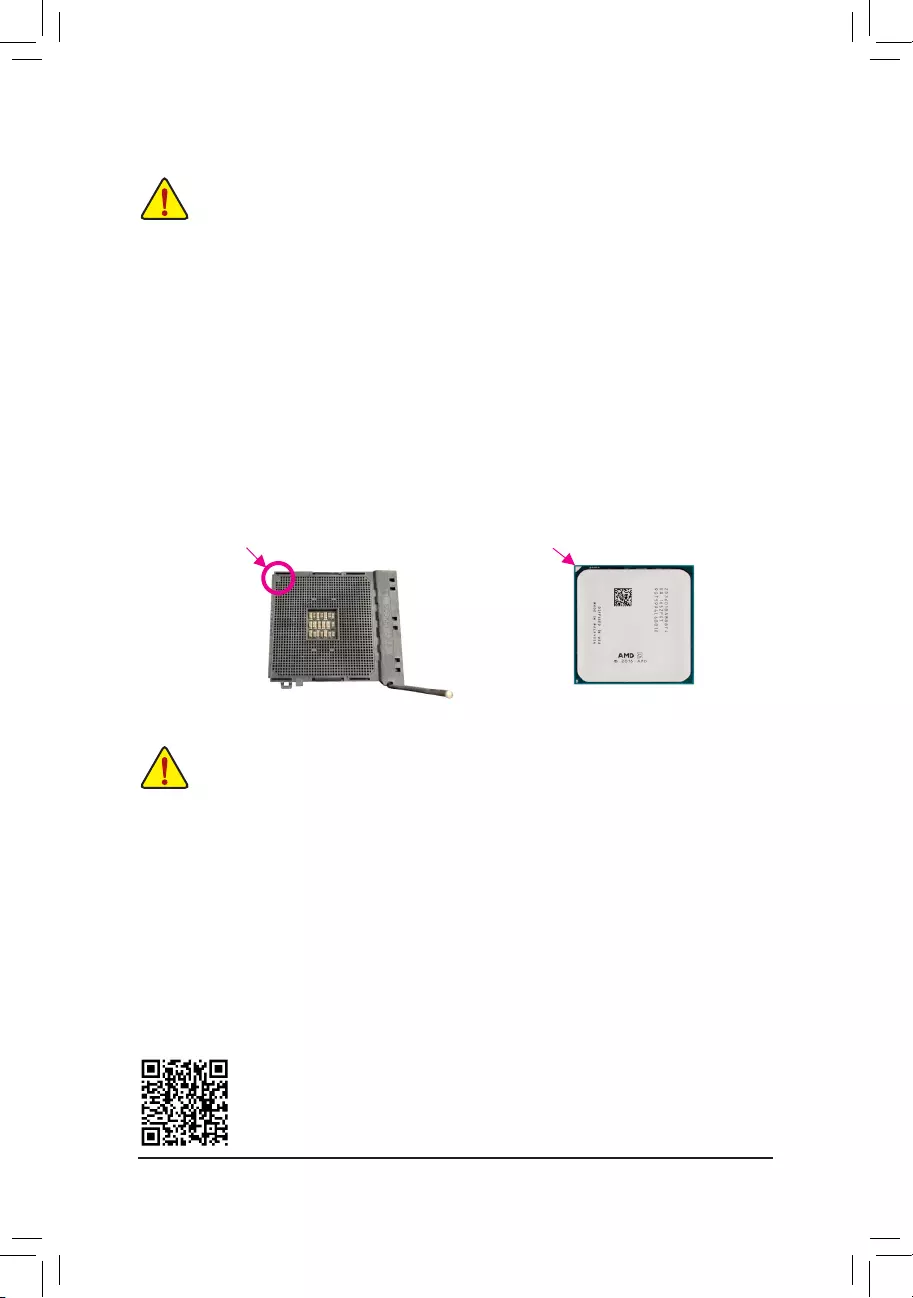
Please visit GIGABYTE’s website for details on hardware installation.
DualChannelMemoryConguration
This motherboard provides four memory sockets and supports Dual Channel Technology. After the memory
is installed, the BIOS will automatically detect the specications and capacity of the memory. Enabling Dual
Channel memory mode will double the original memory bandwidth.
The four memory sockets are divided into two channels and each channel has two memory sockets as following:
Channel A: DDR4_A1, DDR4_A2
Channel B: DDR4_B1, DDR4_B2
1-3 Installing the CPU
Read the following guidelines before you begin to install the CPU:
•Make sure that the motherboard supports the CPU.
(Go to GIGABYTE’s website for the latest CPU support list.)
•Always turn off the computer and unplug the power cord from the power outlet before installing the
CPU to prevent hardware damage.
•Locate the pin one of the CPU. The CPU cannot be inserted if oriented incorrectly.
•Apply an even and thin layer of thermal grease on the surface of the CPU.
•Do not turn on the computer if the CPU cooler is not installed, otherwise overheating and damage
of the CPU may occur.
•Set the CPU host frequency in accordance with the CPU specications. It is not recommended
that the system bus frequency be set beyond hardware specications since it does not meet the
standard requirements for the peripherals. If you wish to set the frequency beyond the standard
specications, please do so according to your hardware specications including the CPU, graphics
card, memory, hard drive, etc.
Installing the CPU
Completely lift up the CPU socket locking lever. Locate the pin one (denoted by a small triangle) of the CPU
socket and the CPU. Once the CPU is positioned into its socket, place one nger down on the middle of the
CPU, lowering the locking lever and latching it into the fully locked position.
Read the following guidelines before you begin to install the memory:
•Make sure that the motherboard supports the memory. It is recommended that memory of the same
capacity, brand, speed, and chips be used.
(Go to GIGABYTE’s website for the latest supported memory speeds and memory modules.)
•Always turn off the computer and unplug the power cord from the power outlet before installing the
memory to prevent hardware damage.
•Memory modules have a foolproof design. A memory module can be installed in only one direction.
If you are unable to insert the memory, switch the direction.
AM4 Socket
A Small Triangle
Marking Denotes Pin
One of the Socket AM4 CPU
A Small Triangle
Marking Denotes CPU
Pin One
1-4 Installing the Memory
— 9 —
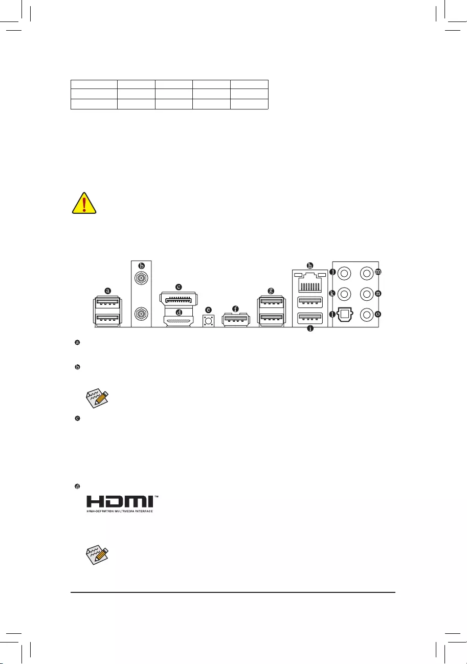
Due to CPU limitations, read the following guidelines before installing the memory in Dual Channel mode.
1. Dual Channel mode cannot be enabled if only one memory module is installed.
2. When enabling Dual Channel mode with two or four memory modules, it is recommended that memory
of the same capacity, brand, speed, and chips be used.
1-5 Installing an Expansion Card
Read the following guidelines before you begin to install an expansion card:
•Make sure the motherboard supports the expansion card. Carefully read the manual that came
with your expansion card.
•Always turn off the computer and unplug the power cord from the power outlet before installing an
expansion card to prevent hardware damage.
1-6 Back Panel Connectors
USB 2.0/1.1 Port
The USB port supports the USB 2.0/1.1 specication. Use this port for USB devices.
SMA Antenna Connectors (2T2R) (Note 1)
Use this connector to connect an antenna.
DisplayPort (Note 2)
DisplayPort delivers high quality digital imaging and audio, supporting bi-directional audio transmission.
DisplayPort can support both DPCP and HDCP 2.3 content protection mechanisms. It provides improved
visuals supporting Rec. 2020 (Wide Color Gamut) and High Dynamic Range (HDR) for Blu-ray UHD
playback. You can use this port to connect your DisplayPort-supported monitor. Note: The DisplayPort
Technology can support a maximum resolution of 5120×2880@60 Hz but the actual resolutions supported
depend on the monitor being used.
HDMI Port (Note 2)
The HDMI port is HDCP 2.3 compliant and supports Dolby TrueHD and DTS
HD Master Audio formats. It also supports up to 192KHz/24bit 7.1-channel
LPCM audio output. You can use this port to connect your HDMI-supported monitor. The maximum
supported resolution is 4096×2160@60 Hz, but the actual resolutions supported are dependent on the
monitor being used.
After installing the DisplayPort/HDMI device, make sure to set the default sound playback device
to DisplayPort/HDMI. (The item name may differ depending on your operating system.)
Recommanded Dual Channel Memory Conguration:
DDR4_A1 DDR4_A2 DDR4_B1 DDR4_B2
2 Modules — — DS/SS — — DS/SS
4 Modules DS/SS DS/SS DS/SS DS/SS
(SS=Single-Sided, DS=Double-Sided, «- -«=No Memory)
Tighten the antennas to the antenna connectors and then aim the antennas correctly for better
signal reception.
— 10 —
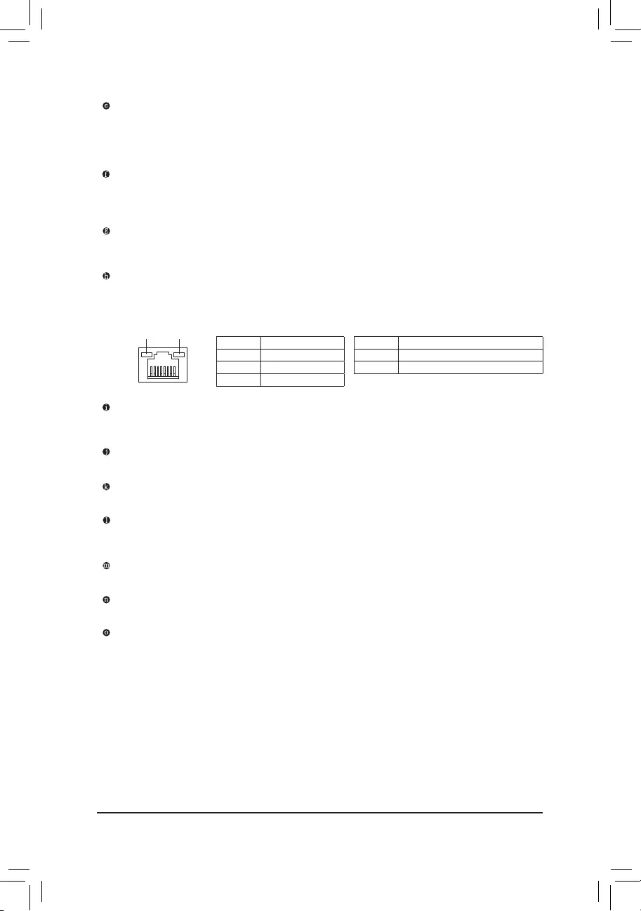
Q-Flash Plus Button (Note 3)
Q-Flash Plus allows you to update the BIOS when your system is off (S5 shutdown state). Save the latest
BIOS on a USB thumb drive and plug it into the Q-Flash Plus port, and then you can now ash the BIOS
automatically by simply pressing the Q-Flash Plus button. The QFLED will ash when the BIOS matching
and ashing activities start and will stop ashing when the BIOS ashing is complete.
USB 3.2 Gen 1 Port (Q-Flash Plus Port)
The USB 3.2 Gen 1 port supports the USB 3.2 Gen 1 specication and is compatible to the USB 2.0
specication. Use this port for USB devices. Before using Q-Flash Plus (Note 3), make sure to insert the
USB ash drive into this port rst.
USB 3.2 Gen 2 Type-A Port (Red)
The USB 3.2 Gen 2 Type-A port supports the USB 3.2 Gen 2 specication and is compatible to the USB
3.2 Gen 1 and USB 2.0 specication. Use this port for USB devices.
RJ-45 LAN Port
The Gigabit Ethernet LAN port provides Internet connection at up to 2.5 Gbps data rate. The following
describes the states of the LAN port LEDs.
USB 3.2 Gen 1 Port
The USB 3.2 Gen 1 port supports the USB 3.2 Gen 1 specication and is compatible to the USB 2.0
specication.
Center/Subwoofer Speaker Out
Use this audio jack to connect center/subwoofer speakers.
Rear Speaker Out
Use this audio jack to connect rear speakers.
Optical S/PDIF Out Connector
This connector provides digital audio out to an external audio system that supports digital optical audio.
Before using this feature, ensure that your audio system provides an optical digital audio in connector.
Line In/Side Speaker Out
The line in jack. Use this audio jack for line in devices such as an optical drive, walkman, etc.
Line Out/Front Speaker Out
The line out jack.
Mic In/Side Speaker Out
The Mic in jack.
Connection/
Speed LED Activity LED
LAN Port
Connection/Speed LED:
State Description
Orange 2.5 Gbps data rate
Green 1 Gbps data rate
Off 100 Mbps data rate
Activity LED:
State Description
Blinking Data transmission or receiving is occurring
Off No data transmission or receiving is occurring
(Note 1) Only for the B550 AORUS ELITE AX V2.
(Note 2) For 3rd Generation AMD Ryzen™ with Radeon™ Graphics processors only.
(Note 3) To enable the Q-Flash Plus function please visit the «Unique Features» webpage of GIGABYTE’s
website.
— 11 —
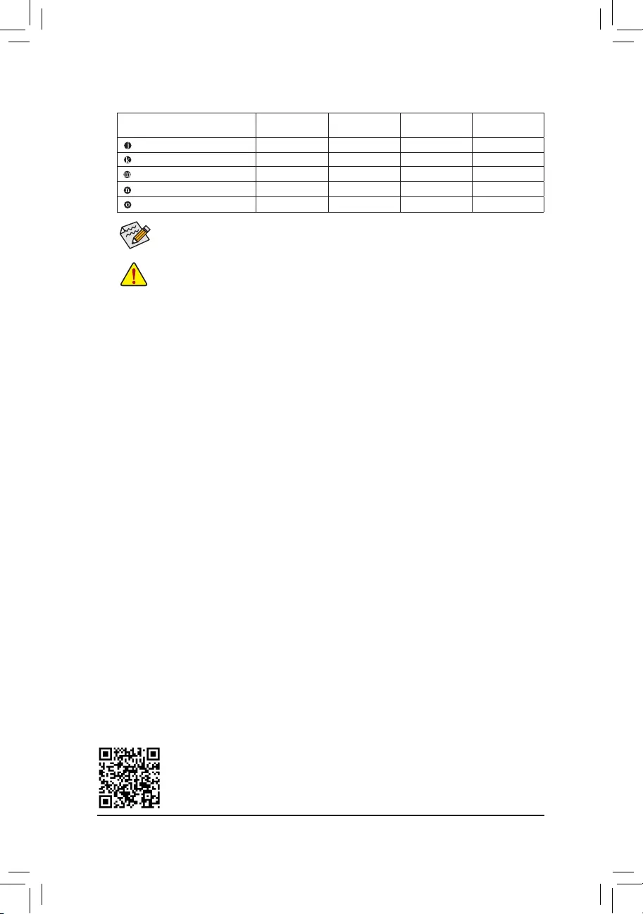
Audio Jack Congurations:
Jack Headphone/
2-channel 4-channel 5.1-channel 7.1-channel
Center/Subwoofer Speaker Out a a
Rear Speaker Out aaa
Line In/Side Speaker Out a
Line Out/Front Speaker Out aaaa
Mic In/Side Speaker Out a
If you want to install a Side Speaker, you need to retask either the Line in or Mic in jack to be Side
Speaker out through the audio driver.
•When removing the cable connected to a back panel connector, rst remove the cable from
your device and then remove it from the motherboard.
•When removing the cable, pull it straight out from the connector. Do not rock it side to side to
prevent an electrical short inside the cable connector.
Please visit GIGABYTE’s website for details on conguring the audio software.
— 12 —
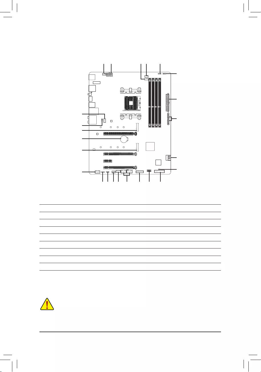
1-7 Internal Connectors
Read the following guidelines before connecting external devices:
•First make sure your devices are compliant with the connectors you wish to connect.
•Before installing the devices, be sure to turn off the devices and your computer. Unplug the power
cord from the power outlet to prevent damage to the devices.
•After installing the device and before turning on the computer, make sure the device cable has
been securely attached to the connector on the motherboard.
1) ATX_12V
2) ATX
3) CPU_FAN
4) SYS_FAN1/2/3
5) CPU_OPT
6) LED_CPU
7) D_LED1/D_LED2
LED_C1/LED_C2
9) SATA3 0/1/2/3
10) M2A_CPU/M2B_SB
11) F_PANEL
12) F_ AUDIO
13) F_U32C
14) F_U32
15) F_USB1/F_USB2
16) TPM
17) CLR_CMOS
18) BAT
1
4
4
10
9
4
2
3
1115
10
9
6
5
8
7
7 8 16
12
14
17
18
13
— 13 —
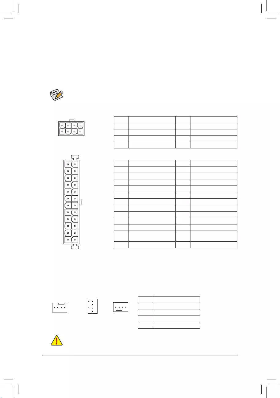
131
2412
ATX
1/2) ATX_12V/ATX (2×4 12V Power Connector and 2×12 Main Power Connector)
With the use of the power connector, the power supply can supply enough stable power to all the components
on the motherboard. Before connecting the power connector, rst make sure the power supply is turned
off and all devices are properly installed. The power connector possesses a foolproof design. Connect the
power supply cable to the power connector in the correct orientation.
The 12V power connector mainly supplies power to the CPU. If the 12V power connector is not connected,
the computer will not start.
To meet expansion requirements, it is recommended that a power supply that can withstand high
power consumption be used (500W or greater). If a power supply is used that does not provide the
required power, the result can lead to an unstable or unbootable system.
ATX:
Pin No. Denition Pin No. Denition
1 3.3V 13 3.3V
2 3.3V 14 -12V
3 GND 15 GND
4 +5V 16 PS_ON (soft On/Off)
5 GND 17 GND
6 +5V 18 GND
7 GND 19 GND
8 Power Good 20 NC
9 5VSB (stand by +5V) 21 +5V
10 +12V 22 +5V
11 +12V (Only for 2×12-pin
ATX)
23 +5V (Only for 2×12-pin ATX)
12 3.3V (Only for 2×12-pin ATX) 24 GND (Only for 2×12-pin ATX)
ATX_12V:
Pin No. Denition Pin No. Denition
1 GND (Only for 2×4-pin 12V) 5 +12V (Only for 2×4-pin 12V)
2 GND (Only for 2×4-pin 12V) 6 +12V (Only for 2×4-pin 12V)
3 GND 7 +12V
4 GND 8 +12V
ATX_12V
41
85
3/4) CPU_FAN/SYS_FAN1/2/3 (Fan Headers)
All fan headers on this motherboard are 4-pin. Most fan headers possess a foolproof insertion design.
When connecting a fan cable, be sure to connect it in the correct orientation (the black connector wire is
the ground wire). The speed control function requires the use of a fan with fan speed control design. For
optimum heat dissipation, it is recommended that a system fan be installed inside the chassis.
Pin No. Denition
1 GND
2 Voltage Speed Control
3 Sense
4 PWM Speed Control
•Be sure to connect fan cables to the fan headers to prevent your CPU and system from
overheating. Overheating may result in damage to the CPU or the system may hang.
•These fan headers are not conguration jumper blocks. Do not place a jumper cap on the headers.
CPU_FAN/SYS_FAN1 SYS_FAN3
1
1
SYS_FAN2
1
— 14 —
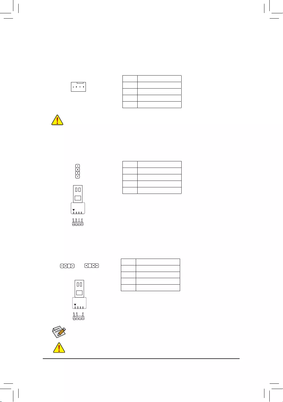
5) CPU_OPT (Water Cooling CPU Fan Header)
The fan header is 4-pin and possesses a foolproof insertion design. Most fan headers possess a foolproof
insertion design. When connecting a fan cable, be sure to connect it in the correct orientation (the black
connector wire is the ground wire). The speed control function requires the use of a fan with fan speed control
design.
1
Pin No. Denition
1 GND
2 Voltage Speed Control
3 Sense
4 PWM Speed Control
•Be sure to connect fan cables to the fan headers to prevent your CPU and system from
overheating. Overheating may result in damage to the CPU or the system may hang.
•These fan headers are not conguration jumper blocks. Do not place a jumper cap on the headers.
6) LED_CPU (CPU Cooler LED Strip/RGB LED Strip Header)
The header can be used to connect a CPU cooler LED strip or a standard 5050 RGB LED strip (12V/G/R/B),
with maximum power rating of 2A (12V) and maximum length of 2m.
Pin No. Denition
1 12V
2 G
3 R
4 B
Connect the CPU cooler LED strip/RGB LED strip to the header. The
power pin (marked with a triangle on the plug) of the LED strip must
be connected to Pin 1 (12V) of this header. Incorrect connection
may lead to the damage of the LED strip.
RGB LED
Strip
1
12V
1
Before installing the devices, be sure to turn off the devices and your computer. Unplug the power
cord from the power outlet to prevent damage to the devices.
For how to turn on/off the lights of the LED strip please visit the «Unique Features» webpage of
GIGABYTE’s website.
7) D_LED1/D_LED2 (Addressable LED Strip Headers)
The headers can be used to connect a standard 5050 addressable LED strip, with maximum power rating
of 5A (5V) and maximum number of 1000 LEDs.
Pin No. Denition
1 V (5V)
2 Data
3 No Pin
4 GND
Connect your addressable LED strip to the header. The power
pin (marked with a triangle on the plug) of the LED strip must be
connected to Pin 1 of the addressable LED strip header. Incorrect
connection may lead to the damage of the LED strip.
Addressable LED
Strip
1
D_LED1 D_LED2
1
F_USB30 F_U
B_
F_ F_
_
B
BS_
B
SB_
B
_S
S_
_
B
_U
_
B
S
123
123
123
123
1
1
1
1
BSS
S
_S
SSU
1 2 3 4 5
S3 BSSS
U
__ 3
F_USB3F
S _
S _
S _
SF
B_
B_
F
_0
S
S
_0F
_F
_
_
__B
U
S _S
_ SF_
B
USB0_B
B_
B_
F_USB3
F_USB303
_
_3U
S_
F_USB30 F_U
B_
F_ F_
_
B
BS_
B
SB_
B
_S
S_
_
B
_U
_
B
S
123
123
123
123
1
1
1
1
BSS
S
_S
SSU
1 2 3 4 5
S3 BSSS
U
__ 3
F_USB3F
S _
S _
S _
SF
B_
B_
F
_0
S
S
_0F
_F
_
_
__B
U
S _S
_ SF_
B
USB0_B
B_
B_
F_USB3
F_USB303
_
_3U
S_
1
— 15 —
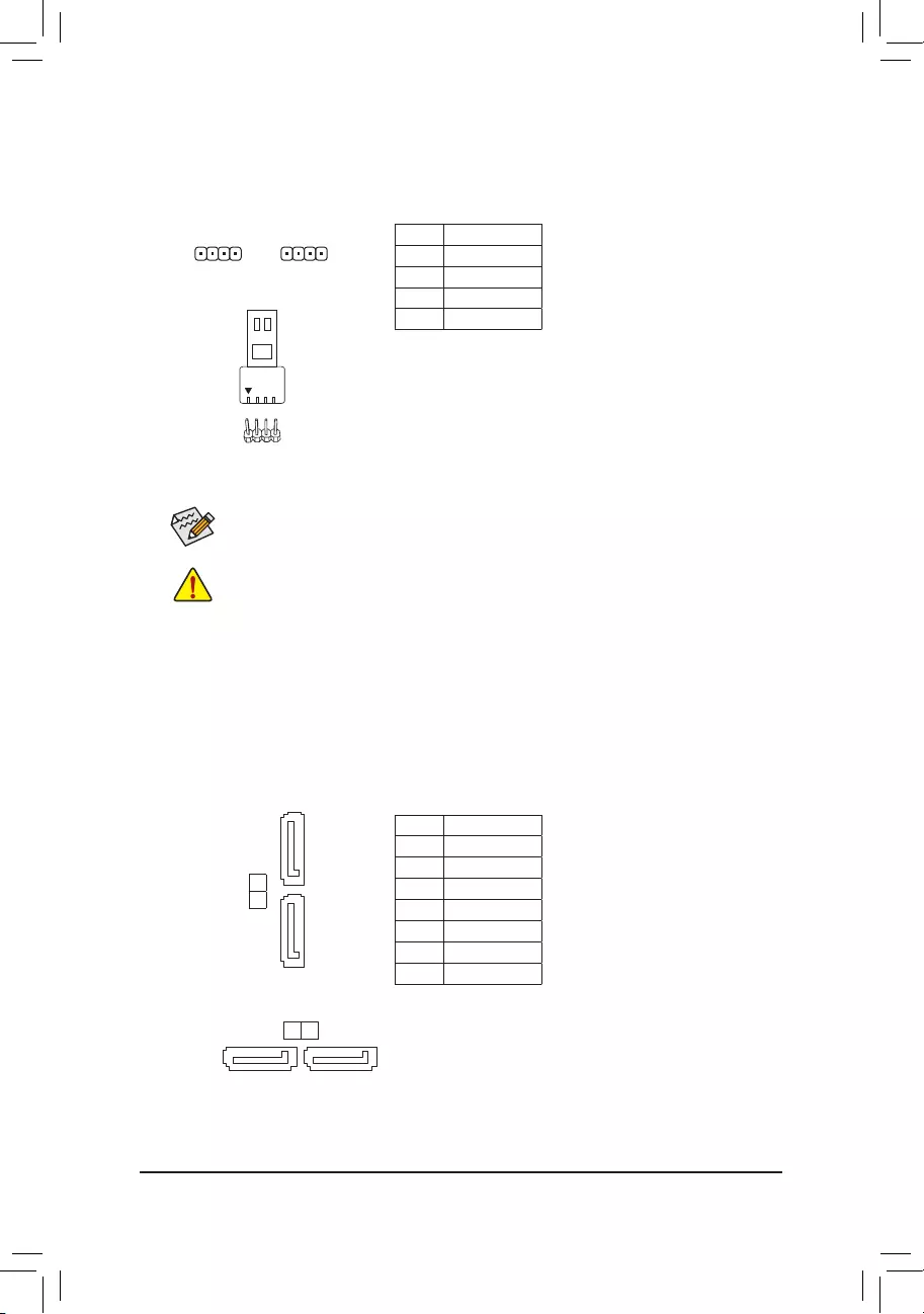
Before installing the devices, be sure to turn off the devices and your computer. Unplug the power
cord from the power outlet to prevent damage to the devices.
LED_C1/LED_C2 (RGB LED Strip Headers)
The headers can be used to connect a standard 5050 RGB LED strip (12V/G/R/B), with maximum power
rating of 2A (12V) and maximum length of 2m.
Pin No. Denition
1 12V
2 G
3 R
4 B
For how to turn on/off the lights of the LED strip please visit the «Unique Features» webpage of
GIGABYTE’s website.
1 1
LED_C1 LED_C2
9) SATA3 0/1/2/3 (SATA 6Gb/s Connectors)
The SATA connectors conform to SATA 6Gb/s standard and are compatible with SATA 3Gb/s and SATA
1.5Gb/s standard. Each SATA connector supports a single SATA device. The SATA connectors support
RAID 0, RAID 1, and RAID 10. Refer to Chapter 3, «Conguring a RAID Set,» for instructions on conguring
a RAID array.
Pin No. Denition
1 GND
2 TXP
3 TXN
4 GND
5 RXN
6 RXP
7 GND
SATA3 0
1
7
1
1 7
SATA3
3 2
Connect your RGB LED strip to the header. The power pin (marked
with a triangle on the plug) of the LED strip must be connected to
Pin 1 (12V) of this header. Incorrect connection may lead to the
damage of the LED strip.
RGB LED Strip
1
12V
— 16 —
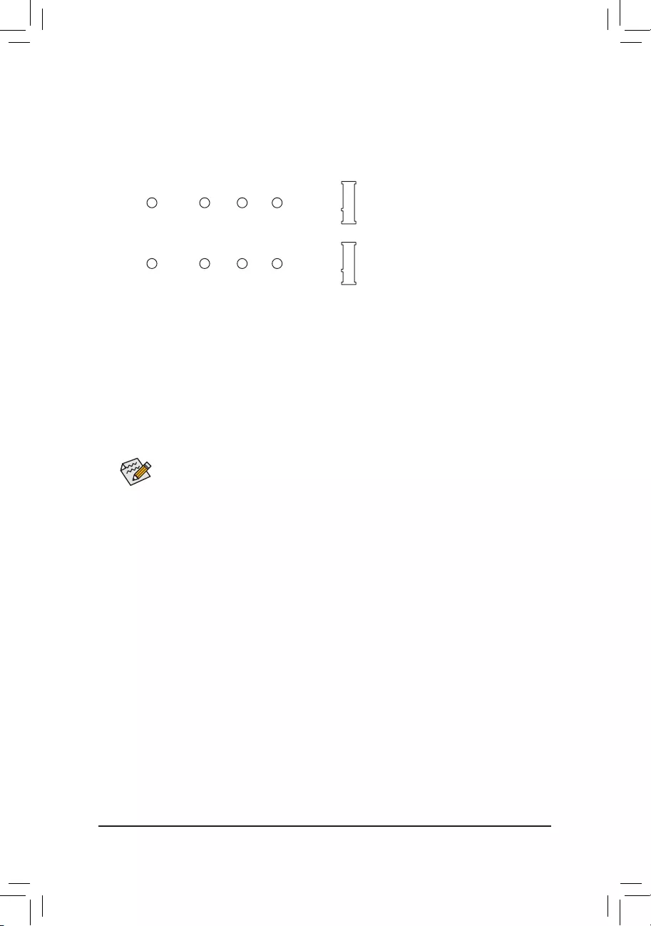
10) M2A_CPU/M2B_SB (M.2 Socket 3 Connectors)
The M.2 connectors support M.2 SATA SSDs or M.2 PCIe SSDs and support RAID conguration. Please
note that an M.2 PCIe SSD cannot be used to create a RAID set either with an M.2 SATA SSD or a SATA
hard drive. Refer to Chapter 3, «Conguring a RAID Set,» for instructions on conguring a RAID array.
Follow the steps below to correctly install an M.2 SSD in the M.2 connector.
Step 1:
Locate the M.2 connector where you will install the M.2 SSD, use a screwdriver to unfasten the screw on
the heatsink and then remove the heatsink.
Step 2:
Locate the proper mounting hole based on the length of your M.2 SSD drive. If needed, move the standoff
to the desired mounting hole. Insert the M.2 SSD into the M.2 connector at an angle.
Step 3:
Press the M.2 SSD down and then secure it with the screw. Replace the heatsink and secure it to the
original hole. Make sure to remove the protective lm from the bottom of the heatsink before replacing the heatsink.
Select the proper hole for the M.2 SSD to be installed and refasten the screw and standoff.
F_USB30 F_U
B_
F_ F_
_
B
BS_
B
SB_
B
_S
S_
_
B
_U
_
B
S
123
123
123
123
1
1
1
1
BSS
S
_S
SSU
1 2 3 4 5
S3 BSSS
U
__ 3
F_USB3F
S _
S _
S _
SF
B_
B_
F
_0
S
S
_0F
_F
_
_
__B
U
S _S
_ SF_
B
USB0_B
B_
B_
F_USB3
F_USB303
_
_3U
S_
80110 60 42
M2A_CPU
F_USB30 F_U
B_
F_ F_
_
B
BS_
B
SB_
B
_S
S_
_
B
_U
_
B
S
123
123
123
123
1
1
1
1
BSS
S
_S
SSU
1 2 3 4 5
S3 BSSS
U
__ 3
F_USB3F
S _
S _
S _
SF
B_
B_
F
_0
S
S
_0F
_F
_
_
__B
U
S _S
_ SF_
B
USB0_B
B_
B_
F_USB3
F_USB303
_
_3U
S_
80110 60 42
M2B_SB (Note)
(Note) Only the B550 AORUS ELITE AX V2 has the heatsink.
— 17 —
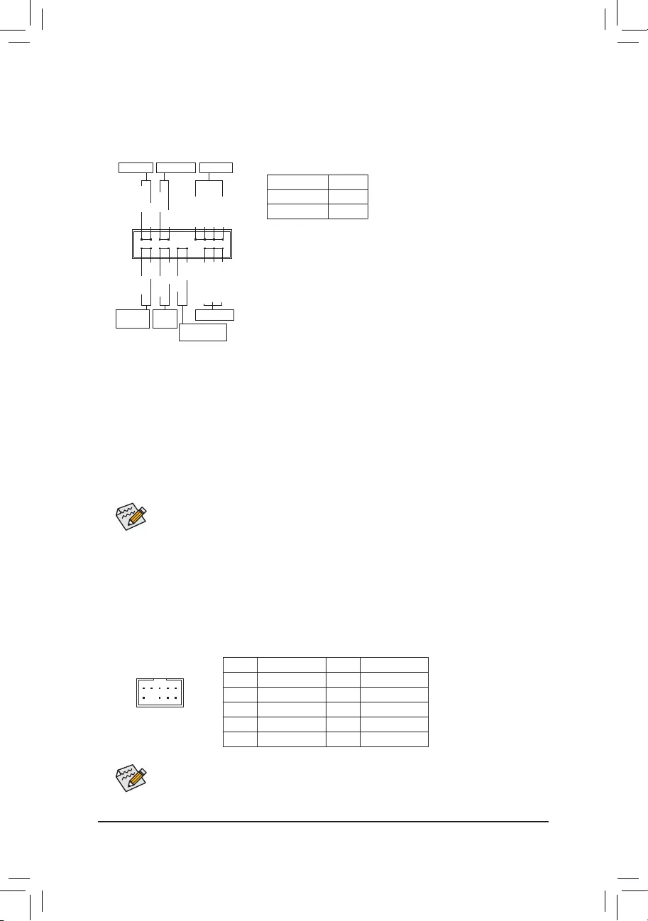
Some chassis provide a front panel audio module that has separated connectors on each wire
instead of a single plug. For information about connecting the front panel audio module that has
different wire assignments, please contact the chassis manufacturer.
11) F_PANEL (Front Panel Header)
Connect the power switch, reset switch, speaker, chassis intrusion switch/sensor and system status indicator
on the chassis to this header according to the pin assignments below. Note the positive and negative pins
before connecting the cables.
12) F_AUDIO (Front Panel Audio Header)
The front panel audio header supports High Denition audio (HD). You may connect your chassis front
panel audio module to this header. Make sure the wire assignments of the module connector match the
pin assignments of the motherboard header. Incorrect connection between the module connector and the
motherboard header will make the device unable to work or even damage it.
F_USB30 F_U
B_
F_ F_
_
B
BS_
B
SB_
B
_S
S_
_
B
_U
_
B
S
123
123
123
123
1
1
1
1
BSS
S
_S
SSU
1 2 3 4 5
S3 BSSS
U
__ 3
F_USB3F
S _
S _
S _
SF
B_
B_
F
_0
S
S
_0F
_F
_
_
__B
U
S _S
_ SF_
B
USB0_B
B_
B_
F_USB3
F_USB303
_
_3U
S_
91
10 2
Pin No. Denition Pin No. Denition
1 MIC2_L 6 Sense
2 GND 7 FAUDIO_JD
3 MIC2_R 8 No Pin
4 NC 9 LINE2_L
5 LINE2_R 10 Sense
The front panel design may differ by chassis. A front panel module mainly consists of power switch,
reset switch, power LED, hard drive activity LED, speaker and etc. When connecting your chassis
front panel module to this header, make sure the wire assignments and the pin assignments are
matched correctly.
System Status LED
S0 On
S3/S4/S5 Off
•PW (Power Switch):
Connects to the power switch on the chassis front panel. You may
congure the way to turn off your system using the power switch
(refer to Chapter 2, «BIOS Setup,» «SettingsPlatform Power,» for more
information).
•SPEAK (Speaker):
Connects to the speaker on the chassis front panel. The system reports
system startup status by issuing a beep code. One single short beep
will be heard if no problem is detected at system startup.
•PLED/PWR_LED (Power LED):
Connects to the power status indicator
on the chassis front panel. The LED is on
when the system is operating. The LED is
off when the system is in S3/S4 sleep state
or powered off (S5).
•HD (Hard Drive Activity LED):
Connects to the hard drive activity LED on the chassis front panel. The LED is on when the hard drive
is reading or writing data.
•RES (Reset Switch):
Connects to the reset switch on the chassis front panel. Press the reset switch to restart the computer
if the computer freezes and fails to perform a normal restart.
•CI (Chassis Intrusion Header):
Connects to the chassis intrusion switch/sensor on the chassis that can detect if the chassis cover has
been removed. This function requires a chassis with a chassis intrusion switch/sensor.
•NC: No connection.
NC
NC
Power LED
1
2
19
20
CI-
CI+
PWR_LED-
PWR_LED+
PLED-
PW-
SPEAK+
SPEAK-
PLED+
PW+
Power LED
HD-
RES+
HD+
RES-
Hard Drive
Activity LED
Reset
Switch Chassis Intrusion
Header
Power Switch Speaker
PWR_LED-
— 18 —
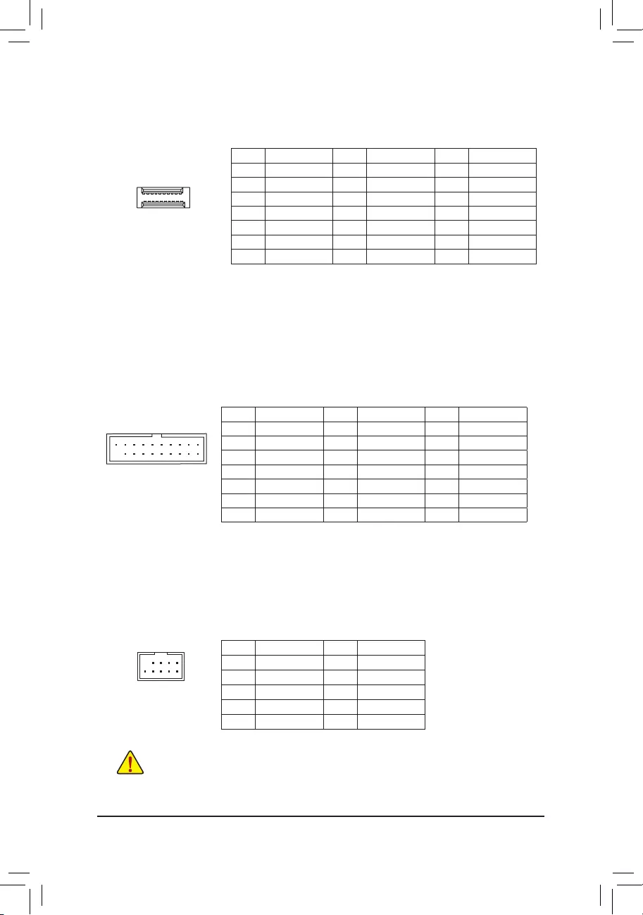
Pin No. Denition Pin No. Denition Pin No. Denition
1 VBUS 8 D1- 15 SSTX2-
2 SSRX1- 9 D1+ 16 GND
3 SSRX1+ 10 NC 17 SSRX2+
4 GND 11 D2+ 18 SSRX2-
5 SSTX1- 12 D2- 19 VBUS
6 SSTX1+ 13 GND 20 No Pin
7 GND 14 SSTX2+
14) F_U32 (USB 3.2 Gen 1 Header)
The header conforms to USB 3.2 Gen 1 and USB 2.0 specication and can provide two USB ports. For
purchasing the optional 3.5″ front panel that provides two USB 3.2 Gen 1 ports, please contact the local
dealer.
F_USB30 F_U
B_
F_ F_
_
B
BS_
B
SB_
B
_S
S_
_
B
_U
_
B
S
123
123
123
123
1
1
1
1
BSS
S
_S
SSU
1 2 3 4 5
S3 BSSS
U
__ 3
F_USB3F
S _
S _
S _
SF
B_
B_
F
_0
S
S
_0F
_F
_
_
__B
U
S _S
_ SF_
B
USB0_B
B_
B_
F_USB3
F_USB303
_
_3U
S_
11
1 10
20
15) F_USB1/F_USB2 (USB 2.0/1.1 Headers)
The headers conform to USB 2.0/1.1 specication. Each USB header can provide two USB ports via an
optional USB bracket. For purchasing the optional USB bracket, please contact the local dealer.
Pin No. Denition Pin No. Denition
1 Power (5V) 6 USB DY+
2 Power (5V) 7 GND
3 USB DX- 8 GND
4 USB DY— 9 No Pin
5 USB DX+ 10 NC
•Do not plug the IEEE 1394 bracket (2×5-pin) cable into the USB 2.0/1.1 header.
•Prior to installing the USB bracket, be sure to turn off your computer and unplug the power cord
from the power outlet to prevent damage to the USB bracket.
10
9
2
1
13) F_U32C (USB Type-C™ Header with USB 3.2 Gen 1 Support)
The header conforms to USB 3.2 Gen 1 specication and can provide one USB port.
Pin No. Denition Pin No. Denition Pin No. Denition
1 VBUS 8 CC1 15 RX2+
2 TX1+ 9 SBU1 16 RX2-
3 TX1- 10 SBU2 17 GND
4 GND 11 VBUS 18 D-
5 RX1+ 12 TX2+ 19 D+
6 RX1- 13 TX2- 20 CC2
7 VBUS 14 GND
F_USB30 F_U
B_
F_ F_
_
B
BS_
B
SB_
B
_S
S_
_
B
_U
_
B
S
123
123
123
123
1
1
1
1
BSS
S
_S
SSU
1 2 3 4 5
S3 BSSS
U
__ 3
F_USB3F
S _
S _
S _
SF
B_
B_
F
_0
S
S
_0F
_F
_
_
__B
U
S _S
_ SF_
B
USB0_B
B_
B_
F_USB3
F_USB303
_
_3U
S_
20
10
11
1
— 19 —
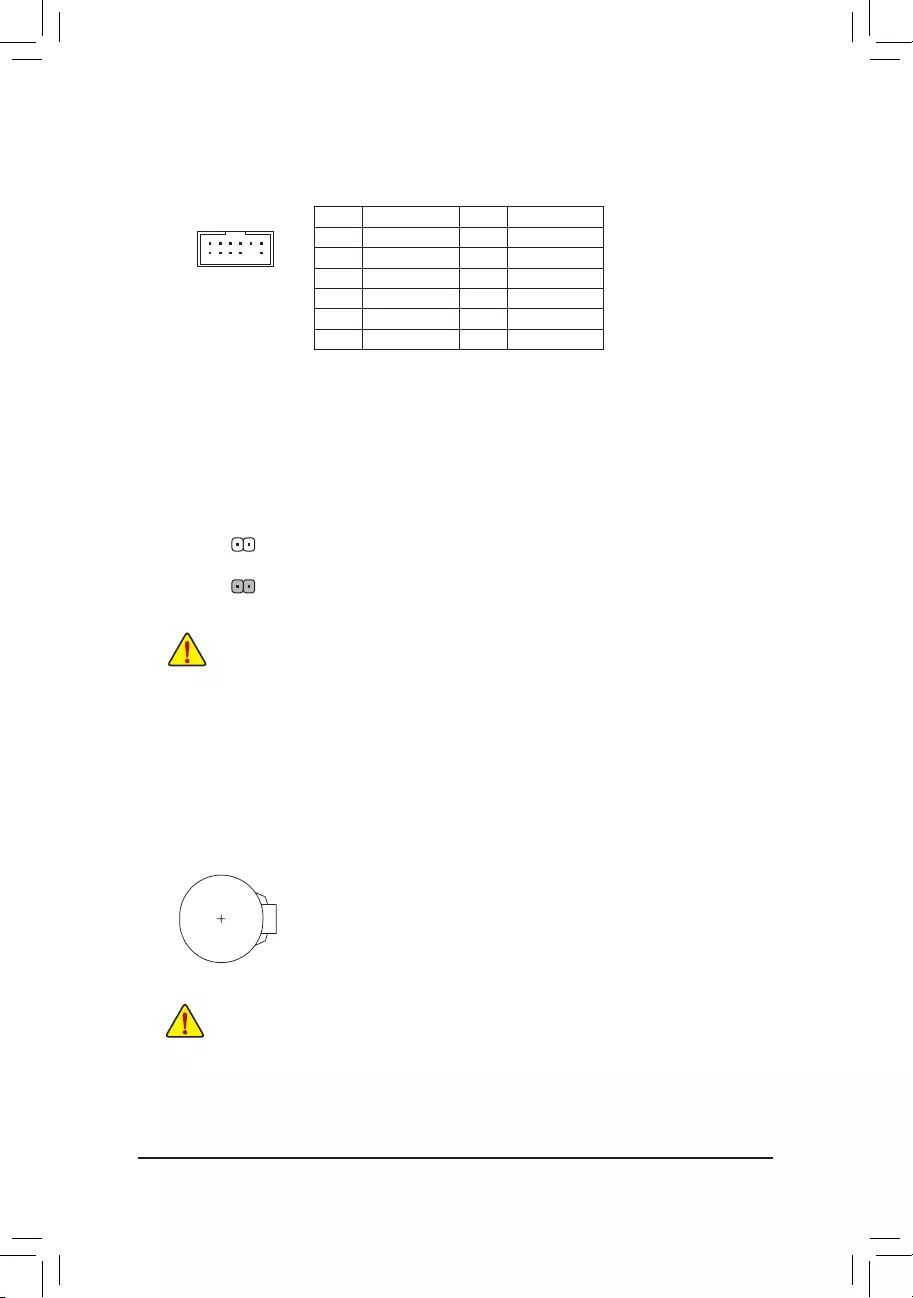
17) CLR_CMOS (Clear CMOS Jumper)
Use this jumper to clear the BIOS conguration and reset the CMOS values to factory defaults. To clear
the CMOS values, use a metal object like a screwdriver to touch the two pins for a few seconds.
•Always turn off your computer before clearing the CMOS values.
•After system restart, go to BIOS Setup to load factory defaults (select Load Optimized Defaults) or
manually congure the BIOS settings (refer to Chapter 2, «BIOS Setup,» for BIOS congurations).
Open: Normal
Short: Clear CMOS Values
18) BAT (Battery)
The battery provides power to keep the values (such as BIOS congurations, date, and time information)
in the CMOS when the computer is turned off. Replace the battery when the battery voltage drops to a low
level, or the CMOS values may not be accurate or may be lost.
You may clear the CMOS values by removing the battery:
1. Turn off your computer and unplug the power cord.
2. Gently remove the battery from the battery holder and wait for one minute. (Or use a metal
object like a screwdriver to touch the positive and negative terminals of the battery holder,
making them short for 5 seconds.)
3. Replace the battery.
4. Plug in the power cord and restart your computer.
•Always turn off your computer and unplug the power cord before replacing the battery.
•Replace the battery with an equivalent one. Damage to your devices may occur if the battery is
replaced with an incorrect model.
•Contact the place of purchase or local dealer if you are not able to replace the battery by yourself
or uncertain about the battery model.
•When installing the battery, note the orientation of the positive side (+) and the negative side (-)
of the battery (the positive side should face up).
•Used batteries must be handled in accordance with local environmental regulations.
16) TPM (Trusted Platform Module Header)
You may connect a TPM (Trusted Platform Module) to this header.
Pin No. Denition Pin No. Denition
1LAD0 7LAD3
2VCC3 8GND
3LAD1 9LFRAME
4No Pin 10 NC
5LAD2 11 SERIRQ
6LCLK 12 LRESET
12
11
2
1
F_USB30 F_U
B_
F_ F_
_
B
BS_
B
SB_
B
_S
S_
_
B
_U
_
B
S
123
123
123
123
1
1
1
1
BSS
S
_S
SSU
1 2 3 4 5
S3 BSSS
U
__ 3
F_USB3F
S _
S _
S _
SF
B_
B_
F
_0
S
S
_0F
_F
_
_
__B
U
S _S
_ SF_
B
USB0_B
B_
B_
F_USB3
F_USB303
_
_3U
S_
— 20 —
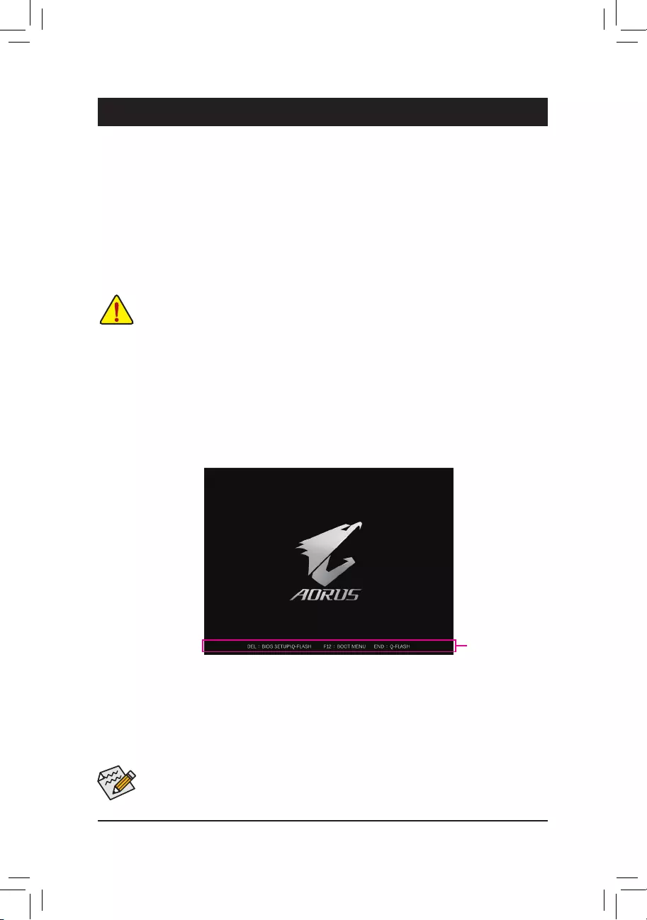
BIOS (Basic Input and Output System) records hardware parameters of the system in the CMOS on the
motherboard. Its major functions include conducting the Power-On Self-Test (POST) during system startup,
saving system parameters and loading operating system, etc. BIOS includes a BIOS Setup program that allows
the user to modify basic system conguration settings or to activate certain system features.
When the power is turned off, the battery on the motherboard supplies the necessary power to the CMOS to
keep the conguration values in the CMOS.
To access the BIOS Setup program, press the <Delete> key during the POST when the power is turned on.
To upgrade the BIOS, use either the GIGABYTE Q-Flash or @BIOS utility.
•Q-Flash allows the user to quickly and easily upgrade or back up BIOS without entering the operating system.
•@BIOS is a Windows-based utility that searches and downloads the latest version of BIOS from the Internet
and updates the BIOS.
Chapter 2 BIOS Setup
•Because BIOS ashing is potentially risky, if you do not encounter problems using the current version of BIOS,
it is recommended that you not ash the BIOS. To ash the BIOS, do it with caution. Inadequate BIOS ashing
may result in system malfunction.
•It is recommended that you not alter the default settings (unless you need to) to prevent system instability or other
unexpected results. Inadequately altering the settings may result in system’s failure to boot. If this occurs, try to
clear the CMOS values and reset the board to default values. (Refer to the «Load Optimized Defaults» section in
this chapter or introductions of the battery/clear CMOS jumper in Chapter 1 for how to clear the CMOS values.)
2-1 Startup Screen
The following startup Logo screen will appear when the computer boots.
Function Keys
•When the system is not stable as usual, select the Load Optimized Defaults item to set your system to its defaults.
•The BIOS Setup menus described in this chapter are for reference only and may differ by BIOS version.
There are two different BIOS modes as follows and you can use the <F2> key to switch between the two modes.
Easy Mode allows users to quickly view their current system information or to make adjustments for optimum
performance. In Easy Mode, you can use your mouse to move through conguration items. The Advanced Mode
provides detailed BIOS settings. You can press the arrow keys on your keyboard to move among the items
and press <Enter> to accept or enter a sub-menu. Or you can use your mouse to select the item you want.
— 21 —
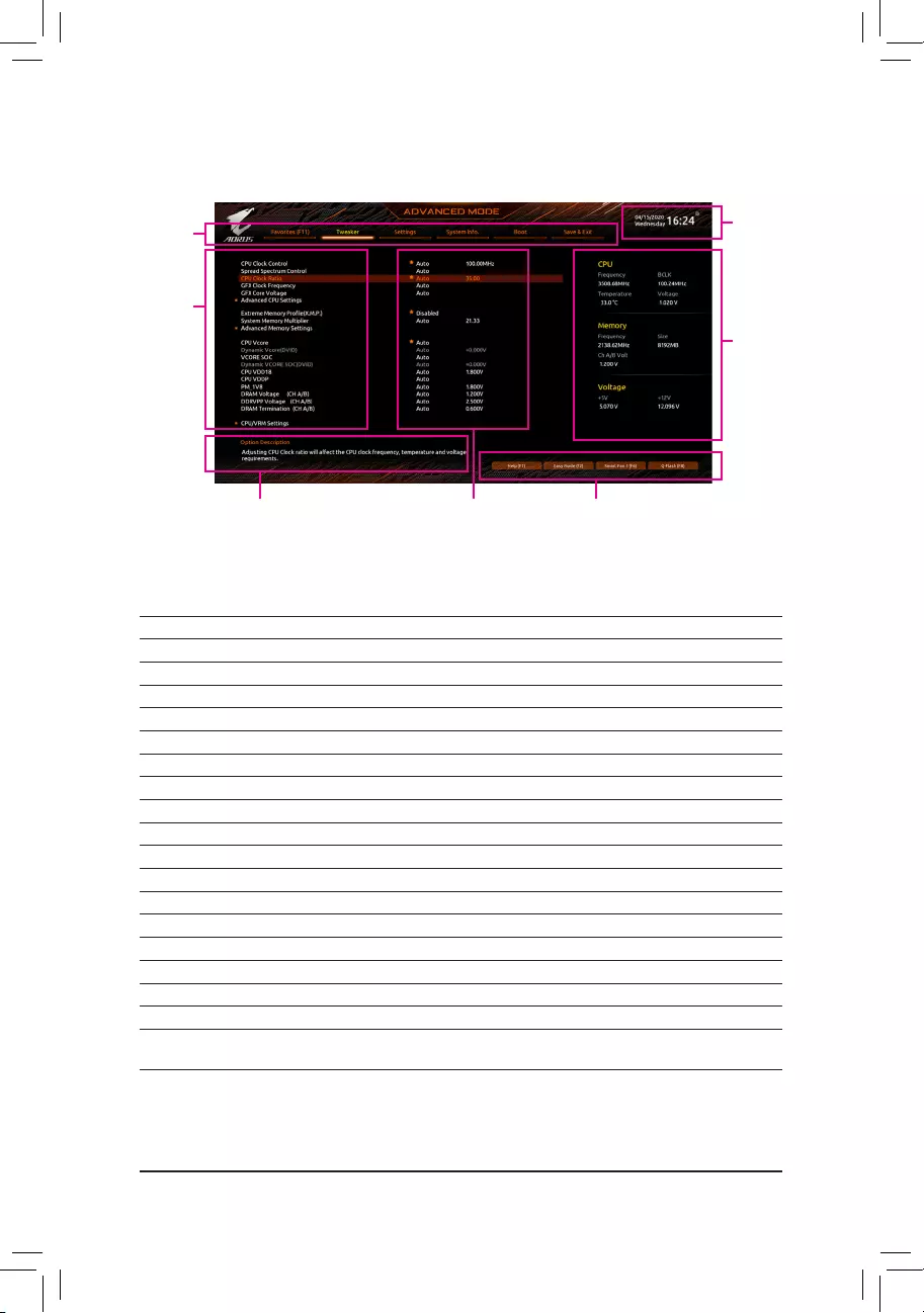
2-2 The Main Menu
Advanced Mode Function Keys
<f><g> Move the selection bar to select a setup menu
<h><i>Move the selection bar to select an conguration item on a menu
<Enter>/Double Click Execute command or enter a menu
<+>/<Page Up> Increase the numeric value or make changes
<—>/<Page Down> Decrease the numeric value or make changes
<F1> Show descriptions of the function keys
<F2> Switch to Easy Mode
<F3> Save the current BIOS settings to a prole
<F4> Load the BIOS settings from a prole created before
<F5> Restore the previous BIOS settings for the current submenus
<F6> Display the Smart Fan 5 screen
<F7> Load the Optimized BIOS default settings for the current submenus
<F8> Access the Q-Flash utility
<F10> Save all the changes and exit the BIOS Setup program
<F11> Switch to the Favorites submenu
<F12> Capture the current screen as an image and save it to your USB drive
<Insert> Add or remove a favorite option
<Ctrl>+<S> Display information on the installed memory
<Esc> Main Menu: Exit the BIOS Setup program
Submenus: Exit current submenu
Hardware
Information
Option Description Current Settings
Setup Menus
Conguration
Items
System
Time
Quick Access Bar allows you to quickly move to
the General Help, Easy Mode, Smart Fan 5, or
Q-Flash screen.
— 22 —
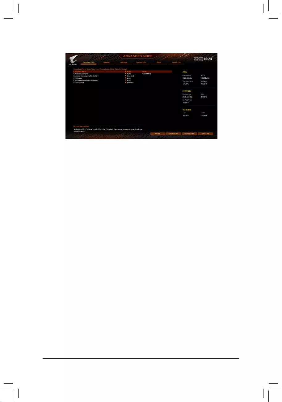
2-3 Favorites (F11)
Set your frequently used options as your favorites and use the <F11> key to quickly switch to the page where
all of your favorite options are located. To add or remove a favorite option, go to its original page and press
<Insert> on the option. The option is marked with a star sign if set as a «favorite.»
— 23 —
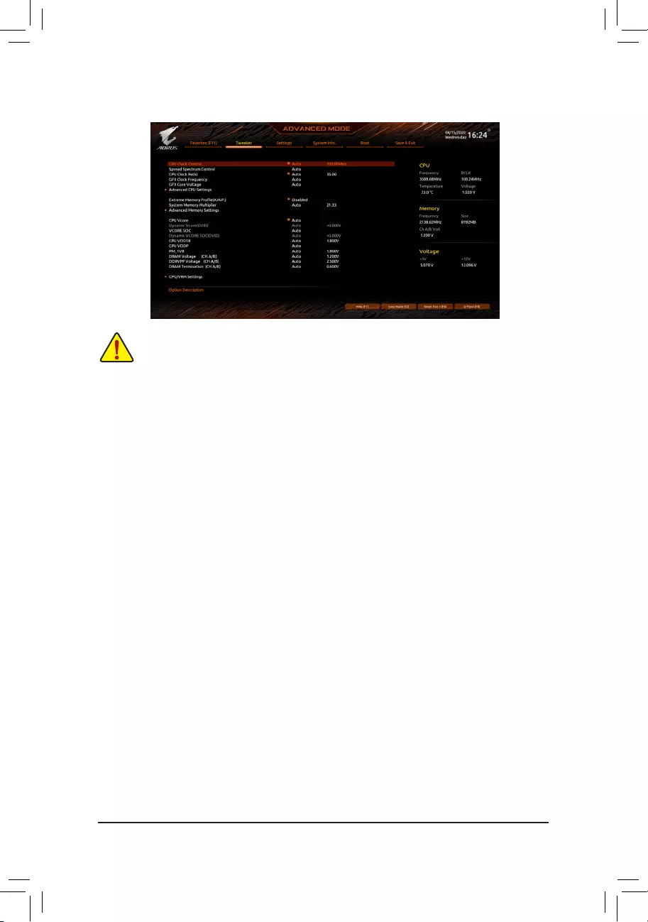
2-4 Tweaker
Whether the system will work stably with the overclock/overvoltage settings you made is dependent on your overall
system congurations. Incorrectly doing overclock/overvoltage may result in damage to CPU, chipset, or memory
and reduce the useful life of these components. This page is for advanced users only and we recommend you not to
alter the default settings to prevent system instability or other unexpected results. (Inadequately altering the settings
may result in system’s failure to boot. If this occurs, clear the CMOS values and reset the board to default values.)
&CPU Clock Control
Allows you to manually set the CPU base clock in 1 MHz increments. (Default: Auto)
Important: It is highly recommended that the CPU frequency be set in accordance with the CPU
specications.
&Spread Spectrum Control
Enables or disables CPU/PCIe Spread Spectrum. (Default: Auto)
&CPU Ratio Mode (Note)
Allows you to set the core ratio for all CPU cores or individual cores. (Default: All cores)
&CCD0 CCX0/1 Ratio (Note)
Allows you to manually set the core ratio for the CPU CCX0, 1 cores. This item is congurable only when
CPU Ratio Mode is set to Per CCX. (Default: Auto)
&CPU Clock Ratio
Allows you to alter the clock ratio for the installed CPU. The adjustable range is dependent on the CPU
being installed.
&GFX Clock Frequency (Note)
Allows you to alter the frequency for the GPU. After you alter the GFX Clock Frequency settings, make
sure to adjust the GFX Core Voltage settings. (Default: Auto)
NOTE: The adjustable range is dependent on the CPU being installed. Auto lets the BIOS automatically
congure this setting.
&GFX Core Voltage (Note)
Allows you to alter the voltage for the GPU. (Default: Auto)
NOTE: The adjustable range is dependent on the CPU being installed. Auto lets the BIOS automatically
congure this setting.
(Note) This item is present only when you install a CPU that supports this feature.
— 24 —

Advanced CPU Settings
&Core Performance Boost (Note 1)
Allows you to determine whether to enable the Core Performance Boost (CPB) technology, a CPU
performance-boost technology. (Default: Auto)
&SVM Mode
Virtualization enhanced by Virtualization Technology will allow a platform to run multiple operating systems
and applications in independent partitions. With virtualization, one computer system can function as multiple
virtual systems. (Default: Disabled)
&AMD Cool&Quiet function
Enabled Lets the AMD Cool’n’Quiet driver dynamically adjust the CPU clock and VID to
reduce heat output from your computer and its power consumption. (Default)
Disabled Disables this function.
&PPC Adjustment (Note 1)
Allows you to x the PState of the CPU. (Default: PState 0)
&Global C-state Control (Note 1)
Allows you to determine whether to let the CPU enter C states. When enabled, the CPU core frequency
will be reduced during system halt state to decrease power consumption. (Default: Auto)
&Power Supply Idle Control (Note 1)
Enables or disables Package C6 State.
Typical Current Idle Disables this function.
Low Current Idle Enables this function.
Auto Lets the BIOS automatically congure this setting. (Default)
&CCD Control (Note 1)
Sets the number of CCDs to be used. (Default: Auto)
&Downcore Control
Allows you to select the number of CPU cores to enable (the number of CPU cores may vary by CPU).
(Default: Auto)
&SMT Mode
Allows you to enable or disable the CPU Simultaneous Multi-Threading technology. (Default: Auto)
&CPPC (Note 1)
Enables or disables the CPPC feature. (Default: Auto)
&CPPC Preferred Cores (Note 1)
Enables or disables the CPPC Preferred Cores feature. (Default: Auto)
&ExtremeMemoryProle(X.M.P.)(Note 2)
Allows the BIOS to read the SPD data on XMP memory module(s) to enhance memory performance when
enabled.
Disabled Disables this function. (Default)
Prole1 Uses Prole 1 settings.
Prole2 (Note 2) Uses Prole 2 settings.
&XMP High Frequency Support (Note 2)
Allows you to select the compatibility level for high-frequency memory. This item is congurable only when
ExtremeMemoryProle(X.M.P.) is set to Prole1 or Prole2. (Default: Auto)
&System Memory Multiplier
Allows you to set the system memory multiplier. Auto sets memory multiplier according to memory SPD
data. (Default: Auto)
(Note 1) This item is present only when you install a CPU that supports this feature.
(Note 2) This item is present only when you install a CPU and a memory module that support this feature.
— 25 —

Advanced Memory Settings
Memory Subtimings
d Standard Timing Control, Advanced Timing Control, CAD Bus Setup Timing, CAD Bus
DriveStrength,DataBusConguration
These sections provide memory timing settings. Note: Your system may become unstable or fail to boot
after you make changes on the memory timings. If this occurs, please reset the board to default values by
loading optimized defaults or clearing the CMOS values.
SPD Info
Displays information on the installed memory.
& CPU Vcore/Dynamic Vcore(DVID)/VCORE SOC/Dynamic VCORE SOC(DVID)/CPU VDD18/
CPU VDDP/PM_1V8/DRAM Voltage (CH A/B)/DDRVPP Voltage (CH A/B)/DRAM Termination
(CH A/B)
These items allow you to adjust the CPU Vcore and memory voltages.
CPU/VRM Settings
This submenu allows you to congure Load-Line Calibration level, over-voltage protection level, over-current
protection level, and PWM phases.
— 26 —
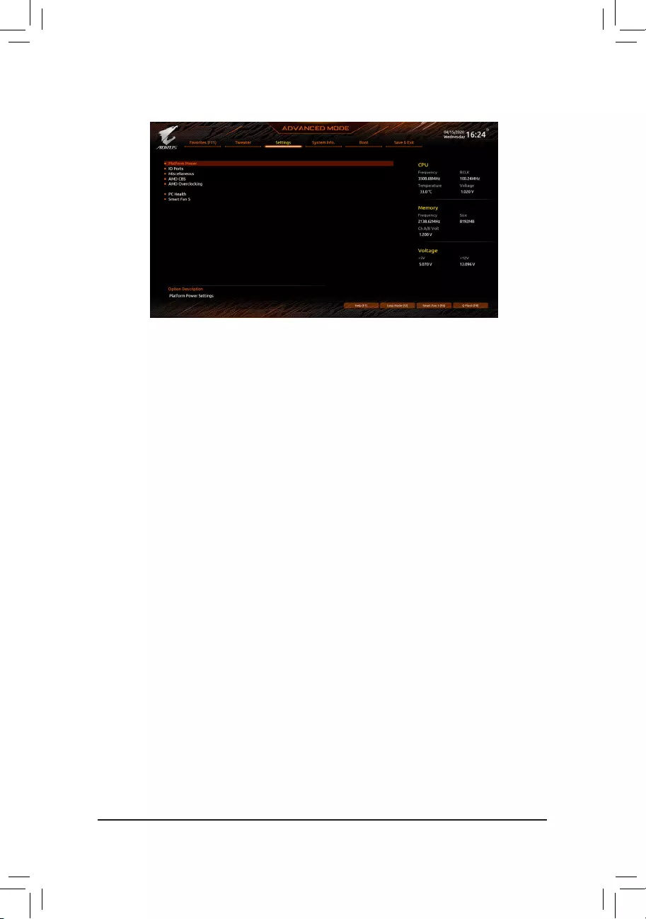
2-5 Settings
Platform Power
&AC BACK
Determines the state of the system after the return of power from an AC power loss.
Memory The system returns to its last known awake state upon the return of the AC power.
Always On The system is turned on upon the return of the AC power.
Always Off The system stays off upon the return of the AC power. (Default)
&ErP
Determines whether to let the system consume least power in S5 (shutdown) state. (Default: Disabled)
Note: When this item is set to Enabled, the Resume by Alarm function becomes unavailable.
&Soft-Off by PWR-BTTN
Congures the way to turn off the computer in MS-DOS mode using the power button.
Instant-Off Press the power button and then the system will be turned off instantly. (Default)
Delay 4 Sec. Press and hold the power button for 4 seconds to turn off the system. If the power
button is pressed for less than 4 seconds, the system will enter suspend mode.
&Power Loading
Enables or disables dummy load. When the power supply is at low load, a self-protection will activate causing
it to shutdown or fail. If this occurs, please set to Enabled. Auto lets the BIOS automatically congure this
setting. (Default: Auto)
&Resume by Alarm
Determines whether to power on the system at a desired time. (Default: Disabled)
If enabled, set the date and time as following:
Wake up day: Turn on the system at a specic time on each day or on a specic day in a month.
Wake up hour/minute/second: Set the time at which the system will be powered on automatically.
Note: When using this function, avoid inadequate shutdown from the operating system or removal of the
AC power, or the settings may not be effective.
&Wake on LAN
Enables or disables the wake on LAN function. (Default: Enabled)
&High Precision Event Timer
Enables or disables High Precision Event Timer (HPET) in the operating system. (Default: Enabled)
&CEC 2019 Ready
Allows you to select whether to allow the system to adjust power consumption when it is in shutdown, idle,
or standby state in order to comply with the CEC (California Energy Commission) 2019 Standards. (Default:
Disabled)
— 27 —

IO Ports
&Initial Display Output
Species the rst initiation of the monitor display from the installed PCI Express graphics card or the onboard
graphics.
IGD Video (Note) Sets the onboard graphics as the rst display.
PCIe 1 Slot Sets the graphics card on the PCIEX16 slot as the rst display. (Default)
PCIe 2 Slot Sets the graphics card on the PCIEX2 slot as the rst display.
&Integrated Graphics (Note)
Enables or disables the onboard graphics function.
Auto The BIOS will automatically enable or disable the onboard graphics depending
on the graphics card being installed. (Default)
Forces Enables the onboard graphics.
Disabled Disables the onboard graphics.
&UMA Mode (Note)
Specify the UMA mode.
Auto Lets the BIOS automatically congure this setting. (Default)
UMA Specied Sets the UMA Frame Buffer Size.
UMA Auto Sets the display resolution.
UMA Game Optimized Adjusts the frame buffer size based on the total system memory size.
This item is congurable only when Integrated Graphics is set to Forces.
&UMA Frame Buffer Size (Note)
Frame buffer size is the total amount of system memory allocated solely for the onboard graphics controller.
MS-DOS, for example, will use only this memory for display. Options are: Auto (default), 64M~2G.
This item is congurable only when UMA Mode is set to UMASpecied.
&Display Resolution (Note)
Allows you to set the display resolution. Options are: Auto (default), 1920×1080 and below, 2560×1600,
3840×2160. This item is congurable only when UMA Mode is set to UMA Auto.
&HD Audio Controller
Enables or disables the onboard audio function. (Default: Enabled)
If you wish to install a 3rd party add-in audio card instead of using the onboard audio, set this item to
Disabled.
&PCIEX16 Bifurcation
Allows you to determine how the bandwidth of the PCIEX16 slot is divided. Options: Auto, PCIE 2×8,
PCIE 1×8/2×4, PCIE 2×4/1×8. (Default: Auto)
&Above 4G Decoding
Enables or disables 64-bit capable devices to be decoded in above 4 GB address space (only if your system
supports 64-bit PCI decoding). Set to Enabled if more than one advanced graphics card are installed and
their drivers are not able to be launched when entering the operating system (because of the limited 4 GB
memory address space). (Default: Disabled)
&Onboard LAN Controller
Enables or disables the onboard LAN function. (Default: Enabled)
If you wish to install a 3rd party add-in network card instead of using the onboard LAN, set this item to
Disabled.
(Note) This item is present only when you install a CPU that supports this feature.
— 28 —

USBConguration
&Legacy USB Support
Allows USB keyboard/mouse to be used in MS-DOS. (Default: Enabled)
&XHCI Hand-off
Determines whether to enable XHCI Hand-off feature for an operating system without XHCI Hand-off
support. (Default: Enabled)
&USB Mass Storage Driver Support
Enables or disables support for USB storage devices. (Default: Enabled)
&Port 60/64 Emulation
Enables or disables emulation of I/O ports 64h and 60h. This should be enabled for full legacy support
for USB keyboards/mice in MS-DOS or in operating system that does not natively support USB devices.
(Default: Disabled)
&Mass Storage Devices
Displays a list of connected USB mass storage devices. This item appears only when a USB storage device
is installed.
NVMeConguration
Displays information on your M.2 NVME PCIe SSD if installed.
SATAConguration
&SATA Mode
Enables or disables RAID for the SATA controllers integrated in the Chipset or congures the SATA controllers
to AHCI mode.
RAID Enables RAID for the SATA controller.
AHCI Congures the SATA controllers to AHCI mode. Advanced Host Controller Interface
(AHCI) is an interface specication that allows the storage driver to enable advanced
Serial ATA features such as Native Command Queuing and hot plug. (Default)
&NVMe RAID mode
Allows you to determine whether to use your M.2 NVMe PCIe SSDs to congure RAID. (Default: Disabled)
&Chipset SATA Port Enable
Enables or disables the integrated SATA controllers. (Default: Enabled)
&Chipset SATA Port 0/1/2/3
Displays the information of the connected SATA device(s).
NetworkStackConguration
&Network Stack
Disables or enables booting from the network to install a GPT format OS, such as installing the OS from
the Windows Deployment Services server. (Default: Disabled)
&IPv4 PXE Support
Enables or disables IPv4 PXE Support. This item is congurable only when Network Stack is enabled.
&IPv4 HTTP Support
Enables or disables HTTP boot support for IPv4. This item is congurable only when Network Stack is
enabled.
&IPv6 PXE Support
Enables or disables IPv6 PXE Support. This item is congurable only when Network Stack is enabled.
&IPv6 HTTP Support
Enables or disables HTTP boot support for IPv6. This item is congurable only when Network Stack is
enabled.
— 29 —

&PXE boot wait time
Allows you to congure how long to wait before you can press <Esc> to abort the PXE boot. This item is
congurable only when Network Stack is enabled. (Default: 0)
&Media detect count
Allows you to set the number of times to check the presence of media. This item is congurable only when
Network Stack is enabled. (Default: 1)
Realtek PCIe 2.5GBE Family Controller
This sub-menu provides information on LAN conguration and related conguration options.
Miscellaneous
&LEDs in System Power On State
Allows you to enable or disable motherboard LED lighting when the system is on.
Off Disables the selected lighting mode when the system is on.
On Enables the selected lighting mode when the system is on. (Default)
&LEDs in Sleep, Hibernation, and Soft Off States
Allows you to set the lighting mode of the motherboard LEDs in system S3/S4/S5 state.
This item is congurable when LEDs in System Power On State is set to On.
Off Disables the selected lighting mode when the system enters S3/S4/S5 state. (Default)
On Enables the selected lighting mode when the system enters S3/S4/S5 state.
&PCIeSlotConguration
Allows you to set the operation mode of the PCI Express slots to Gen 1, Gen 2, Gen 3, or Gen 4 (Note). Actual
operation mode is subject to the hardware specication of each slot. Auto lets the BIOS automatically
congure this setting. (Default: Auto)
&3DMark01 Enhancement
Allows you to determine whether to enhance some legacy benchmark performance. (Default: Disabled)
&IOMMU
Enables or disables AMD IOMMU support. (Default: Auto)
&AMD CPU fTPM
Enables or disables the TPM 2.0 function integrated in the AMD CPU. (Default: Disabled)
Trusted Computing
Enables or disables Trusted Platform Module (TPM).
AMD CBS
This sub-menu provides AMD CBS-related conguration options.
PC Health
&Reset Case Open Status
Disabled Keeps or clears the record of previous chassis intrusion status. (Default)
Enabled Clears the record of previous chassis intrusion status and the Case Open eld will
show «No» at next boot.
&Case Open
Displays the detection status of the chassis intrusion detection device attached to the motherboard CI
header. If the system chassis cover is removed, this eld will show «Yes», otherwise it will show «No». To
clear the chassis intrusion status record, set Reset Case Open Status to Enabled, save the settings to
the CMOS, and then restart your system.
(Note) This item is present only when you install a CPU that supports this feature.
— 30 —

& CPU Vcore/CPU VDDP/DRAM Channel A/B Voltage/+3.3V/+5V/+12V/VCORE SOC
Displays the current system voltages.
Smart Fan 5
&Monitor
Allows you to select a target to monitor and to make further adjustment. (Default: CPU FAN)
&Fan Speed Control
Allows you to determine whether to enable the fan speed control function and adjust the fan speed.
Normal Allows the fan to run at different speeds according to the temperature. You can adjust
the fan speed with System Information Viewer based on your system requirements.
(Default)
Silent Allows the fan to run at slow speeds.
Manual Allows you to control the fan speed in the curve graph.
Full Speed Allows the fan to run at full speeds.
&Fan Control Use Temperature Input
Allows you to select the reference temperature for fan speed control.
&Temperature Interval
Allows you to select the temperature interval for fan speed change.
&Fan Control mode
Auto Lets the BIOS automatically detect the type of fan installed and sets the optimal control
mode. (Default)
Voltage Voltage mode is recommended for a 3-pin fan.
PWM PWM mode is recommended for a 4-pin fan.
&Fan Stop
Enables or disables the fan stop function. You can set the temperature limit using the temperature curve.
The fan or pump stops operation when the temperature is lower than the limit. (Default: Disabled)
&Temperature
Displays the current temperature of the selected target area.
&Fan Speed
Displays current fan speeds.
&Flow Rate
Displays the ow rate of your water cooling system.
&Temperature Warning Control
Sets the warning threshold for temperature. When temperature exceeds the threshold, BIOS will emit
warning sound. Options are: Disabled (default), 60oC/140oF, 70oC/158oF, 80oC/176oF, 90oC/194oF.
&Fan Fail Warning
Allows the system to emit warning sound if the fan is not connected or fails. Check the fan condition or fan
connection when this occurs. (Default: Disabled)
— 31 —
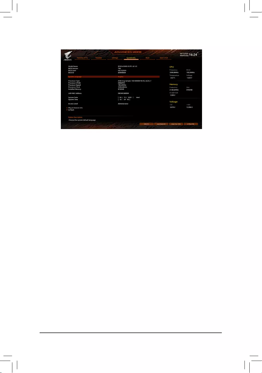
2-6 System Info.
This section provides information on your motherboard model and BIOS version. You can also select the default
language used by the BIOS and manually set the system time.
&System Language
Selects the default language used by the BIOS.
&System Date
Sets the system date. The date format is week (read-only), month, date, and year. Use <Enter> to switch
between the Month, Date, and Year elds and use the <Page Up> or <Page Down> key to set the desired
value.
&System Time
Sets the system time. The time format is hour, minute, and second. For example, 1 p.m. is 13:00:00. Use
<Enter> to switch between the Hour, Minute, and Second elds and use the <Page Up> or <Page Down>
key to set the desired value.
&Access Level
Displays the current access level depending on the type of password protection used. (If no password is
set, the default will display as Administrator.) The Administrator level allows you to make changes to all
BIOS settings; the User level only allows you to make changes to certain BIOS settings but not all.
Plug in Devices Info
Displays information on your SATA, PCI Express, and M.2 devices if installed.
Q-Flash
Allows you to access the Q-Flash utility to update the BIOS or back up the current BIOS conguration.
— 32 —
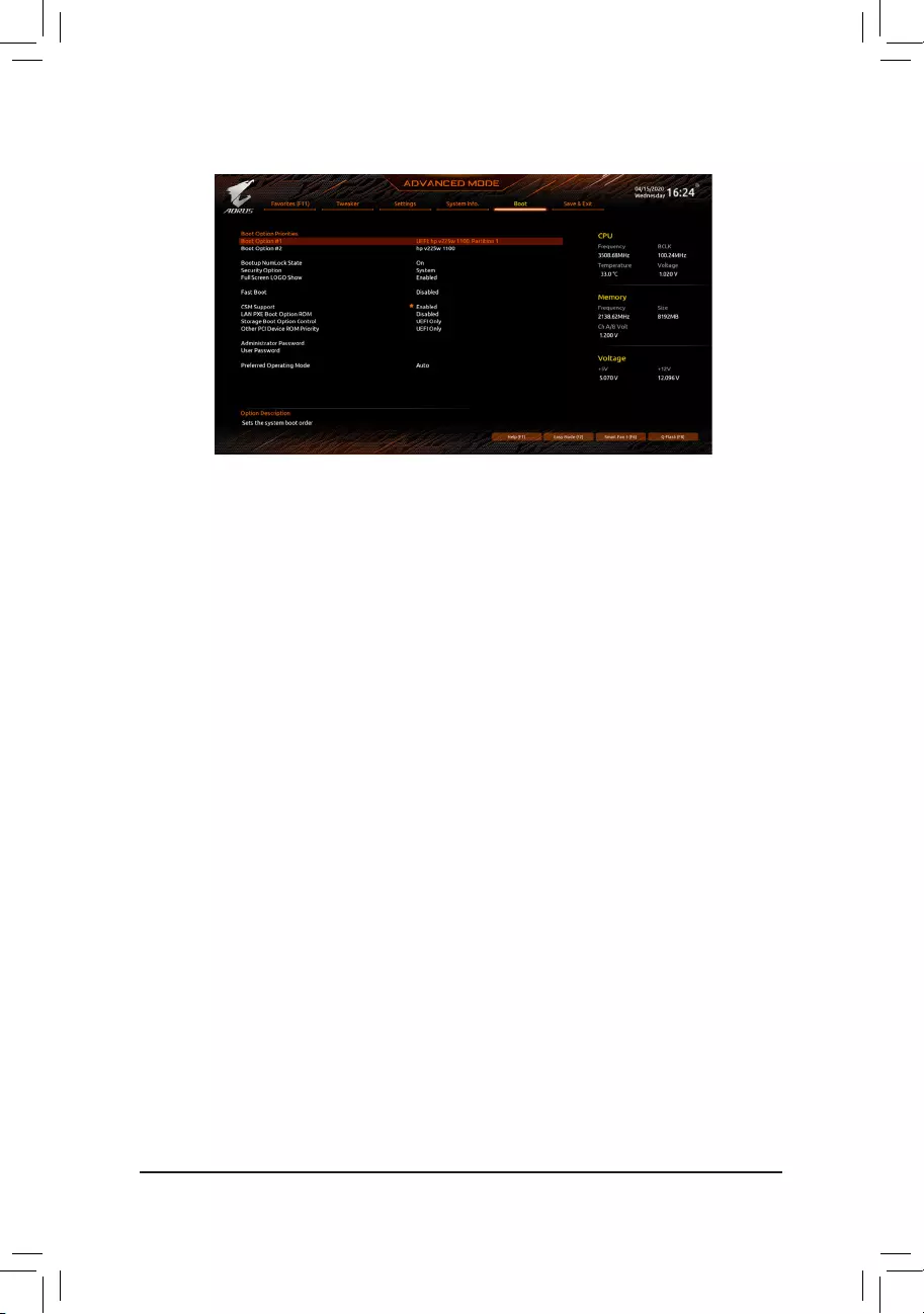
2-7 Boot
&Boot Option Priorities
Species the overall boot order from the available devices. Removable storage devices that support GPT
format will be prexed with «UEFI:» string on the boot device list. To boot from an operating system that
supports GPT partitioning, select the device prexed with «UEFI:» string.
Or if you want to install an operating system that supports GPT partitioning such as Windows 10 64-bit,
select the optical drive that contains the Windows 10 64-bit installation disc and is prexed with «UEFI:»
string.
&Bootup NumLock State
Enables or disables Numlock feature on the numeric keypad of the keyboard after the POST. (Default: On)
&Security Option
Species whether a password is required every time the system boots, or only when you enter BIOS Setup.
After conguring this item, set the password(s) under the Administrator Password/User Password item.
Setup A password is only required for entering the BIOS Setup program.
System A password is required for booting the system and for entering the BIOS Setup program.
(Default)
&Full Screen LOGO Show
Allows you to determine whether to display the GIGABYTE Logo at system startup. Disabled skips the
GIGABYTE Logo when the system starts up. (Default: Enabled)
&Fast Boot
Enables or disables Fast Boot to shorten the OS boot process. Ultra Fast provides the fastest bootup
speed. (Default: Disabled)
&SATA Support
Last Boot SATA Devices Only Except for the previous boot drive, all SATA devices are disabled
before the OS boot process completes. (Default)
All SATA Devices All SATA devices are functional in the operating system and during the POST.
This item is congurable only when Fast Boot is set to Enabled or Ultra Fast.
&NVMe Support
Allows you to enable or disable NVMe device(s). (Default: Enabled)
This item is congurable only when Fast Boot is set to Enabled or Ultra Fast.
— 33 —

&VGA Support
Allows you to select which type of operating system to boot.
Auto Enables legacy option ROM only.
EFI Driver Enables EFI option ROM. (Default)
This item is congurable only when Fast Boot is set to Enabled or Ultra Fast.
&USB Support
Disabled All USB devices are disabled before the OS boot process completes.
Full Initial All USB devices are functional in the operating system and during the POST.
(Default)
Partial Initial Part of the USB devices are disabled before the OS boot process completes.
This item is congurable only when Fast Boot is set to Enabled. This function is disabled when Fast Boot
is set to Ultra Fast.
&NetWork Stack Driver Support
Disabled Disables booting from the network. (Default)
Enabled Enables booting from the network.
This item is congurable only when Fast Boot is set to Enabled or Ultra Fast.
&CSM Support
Enables or disables UEFI CSM (Compatibility Support Module) to support a legacy PC boot process.
Disabled Disables UEFI CSM and supports UEFI BIOS boot process only.
Enabled Enables UEFI CSM. (Default)
&LAN PXE Boot Option ROM
Allows you to select whether to enable the legacy option ROM for the LAN controller. (Default: Disabled)
This item is congurable only when CSM Support is set to Enabled.
&Storage Boot Option Control
Allows you to select whether to enable the UEFI or legacy option ROM for the storage device controller.
Disabled Disables option ROM.
UEFI Only Enables UEFI option ROM only. (Default)
Legacy Only Enables legacy option ROM only.
This item is congurable only when CSM Support is set to Enabled.
&Other PCI Device ROM Priority
Allows you to select whether to enable the UEFI or Legacy option ROM for the PCI device controller other
than the LAN, storage device, and graphics controllers.
Disabled Disables option ROM.
UEFI Only Enables UEFI option ROM only. (Default)
Legacy Only Enables legacy option ROM only.
This item is congurable only when CSM Support is set to Enabled.
&Administrator Password
Allows you to congure an administrator password. Press <Enter> on this item, type the password, and
then press <Enter>. You will be requested to conrm the password. Type the password again and press
<Enter>. You must enter the administrator password (or user password) at system startup and when entering
BIOS Setup. Differing from the user password, the administrator password allows you to make changes to
all BIOS settings.
— 34 —

&User Password
Allows you to congure a user password. Press <Enter> on this item, type the password, and then press
<Enter>. You will be requested to conrm the password. Type the password again and press <Enter>.
You must enter the administrator password (or user password) at system startup and when entering BIOS
Setup. However, the user password only allows you to make changes to certain BIOS settings but not all.
To cancel the password, press <Enter> on the password item and when requested for the password, enter
the correct one rst. When prompted for a new password, press <Enter> without entering any password.
Press <Enter> again when prompted to conrm.
NOTE: Before setting the User Password, be sure to set the Administrator Password rst.
Secure Boot
Allows you to enable or disable Secure Boot and congure related settings. This item is congurable only
when CSM Support is set to Disabled.
&Preferred Operating Mode
Allows you to select whether to enter Easy mode or Advanced mode after entering BIOS Setup. Auto
enters the BIOS mode where it was last time. (Default: Auto)
— 35 —
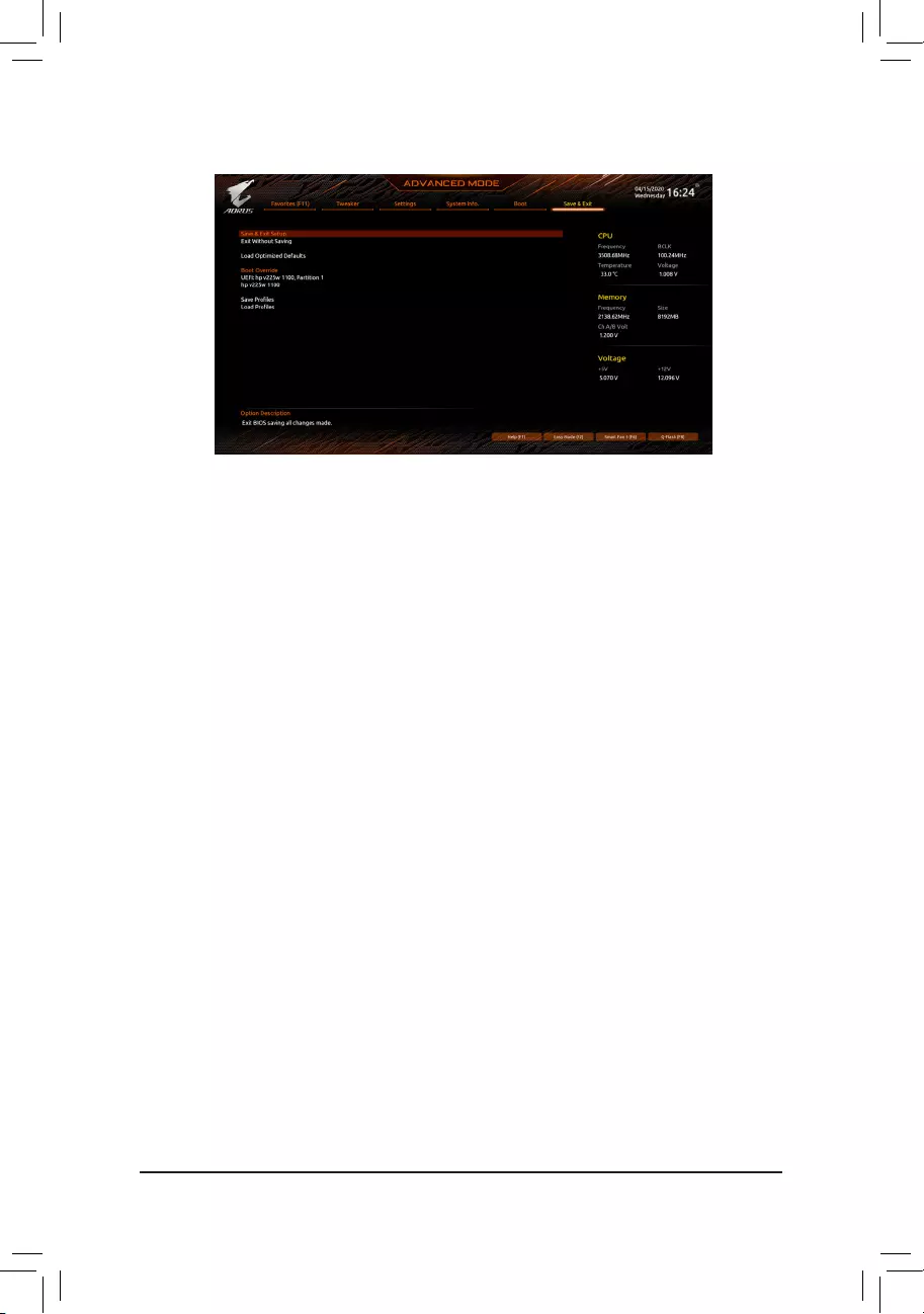
2-8 Save & Exit
&Save & Exit Setup
Press <Enter> on this item and select Yes. This saves the changes to the CMOS and exits the BIOS Setup
program. Select No or press <Esc> to return to the BIOS Setup Main Menu.
&Exit Without Saving
Press <Enter> on this item and select Yes. This exits the BIOS Setup without saving the changes made
in BIOS Setup to the CMOS. Select No or press <Esc> to return to the BIOS Setup Main Menu.
&Load Optimized Defaults
Press <Enter> on this item and select Yes to load the optimal BIOS default settings. The BIOS defaults
settings help the system to operate in optimum state. Always load the Optimized defaults after updating
the BIOS or after clearing the CMOS values.
&Boot Override
Allows you to select a device to boot immediately. Press <Enter> on the device you select and select Yes
to conrm. Your system will restart automatically and boot from that device.
&SaveProles
This function allows you to save the current BIOS settings to a prole. You can create up to 8 proles and
save as Setup Prole 1~ Setup Prole 8. Press <Enter> to complete. Or you can select Select File in
HDD/FDD/USB to save the prole to your storage device.
&LoadProles
If your system becomes unstable and you have loaded the BIOS default settings, you can use this function
to load the BIOS settings from a prole created before, without the hassles of reconguring the BIOS
settings. First select the prole you wish to load and then press <Enter> to complete. You can select Select
File in HDD/FDD/USB to input the prole previously created from your storage device or load the prole
automatically created by the BIOS, such as reverting the BIOS settings to the last settings that worked
properly (last known good record).
— 36 —
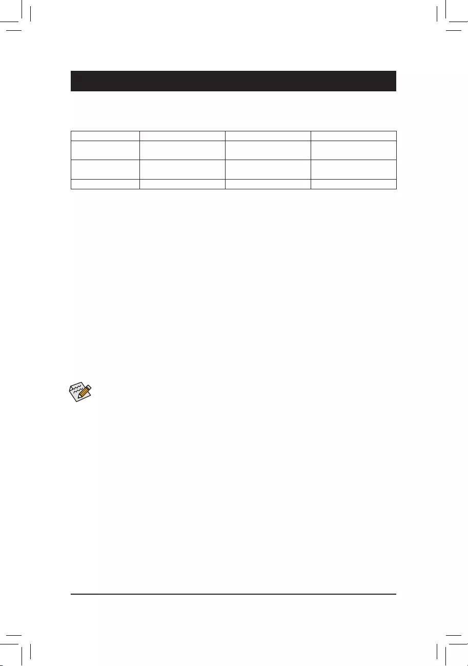
Chapter 3 Appendix
3-1 ConguringaRAIDSet
(Note) An M.2 PCIe SSD cannot be used to set up a RAID set either with an M.2 SATA SSD or a SATA hard drive.
C.UEFIRAIDConguration
Steps:
1. In BIOS Setup, go to Boot and set CSM Support to Disabled. Save the changes and exit BIOS Setup.
2. After the system reboot, enter BIOS Setup again. Then enter the SettingsIO PortsRAIDXpert2
CongurationUtility sub-menu.
3. On the RAIDXpert2CongurationUtility screen, press <Enter> on Array Management to enter the Create
Array screen. Then, select a RAID level. RAID levels supported include RAID 0, RAID 1, and RAID 10 (the
selections available depend on the number of the hard drives being installed). Next, press <Enter> on Select
Physical Disks to enter the Select Physical Disks screen.
4. On the Select Physical Disks screen, select the hard drives to be included in the RAID array and set them
to Enabled. Next, use the down arrow key to move to Apply Changes and press <Enter>. Then return
to the previous screen and set the Select CacheTagSize, Read Cache Policy and Write Cache Policy.
5. Move to Create Array and press <Enter> to begin.
6. After completing, you’ll be brought back to the Array Management screen. Under Manage Array Properties
you can see the new RAID volume and information on RAID level, array name, array capacity, etc.
Before you begin, please prepare the following items:
•At least two SATA hard drives or SSDs. (Note) (To ensure optimal performance, it is recommended that you use
two hard drives with identical model and capacity).
•Windows setup disc.
•Motherboard driver disc.
•A USB thumb drive.
ConguringtheOnboardSATAController
A. Installing SATA hard drive(s) in your computer
Install the hard drives/SSDs in the SATA/M.2 connectors on the motherboard. Then connect the power connectors
from your power supply to the hard drives.
B.ConguringSATAcontrollermodeinBIOSSetup
Make sure to congure the SATA controller mode correctly in system BIOS Setup.
Steps:
Turn on your computer and press <Delete> to enter BIOS Setup during the POST (Power-On Self-Test). Under
SettingsIO Ports, set SATACongurationSATAMode to RAID. Then save the settings and restart your
computer. (If you want to use NVMe PCIe SSDs to congure RAID, make sure to set NVMe RAID mode to
Enabled.)
RAID Levels
RAID 0 RAID 1 RAID 10
Minimum Number of
Hard Drives ≥2 2 4
Array Capacity Number of hard drives *
Size of the smallest drive
Size of the smallest drive (Number of hard drives/2) *
Size of the smallest drive
Fault Tolerance No Yes Yes
The BIOS Setup menus described in this section may differ from the exact settings for your
motherboard. The actual BIOS Setup menu options you will see shall depend on the motherboard
you have and the BIOS version.
— 37 —
Please visit GIGABYTE’s website for details on conguring a RAID array.
Install the RAID driver and operating system
With the correct BIOS settings, you are ready to install the operating system.
Installing the Operating System
As some operating systems already include RAID driver, you do not need to install separate RAID driver during
the Windows installation process. After the operating system is installed, we recommend that you install all
required drivers from the motherboard driver disc using «Xpress Install» to ensure system performance and
compatibility. If the operating system to be installed requires that you provide additional RAID driver during the
OS installation process, please refer to the steps below:
1. Copy the Hw10 folder under the BootDrv folder in the driver disc to your USB thumb drive.
2. Boot from the Windows setup disc and perform standard OS installation steps. When the screen requesting
you to load the driver appears, select Browse.
3. Insert the USB thumb drive and then browse to the location of the driver. The location of the drivers is as
follows:
Hw10RAIDx64
4. Select AMD-RAID Bottom Device rst and click Next to load the driver. Then select AMD-RAID Controller
and click Next to load the driver. Finally, continue the OS installation.
— 38 —
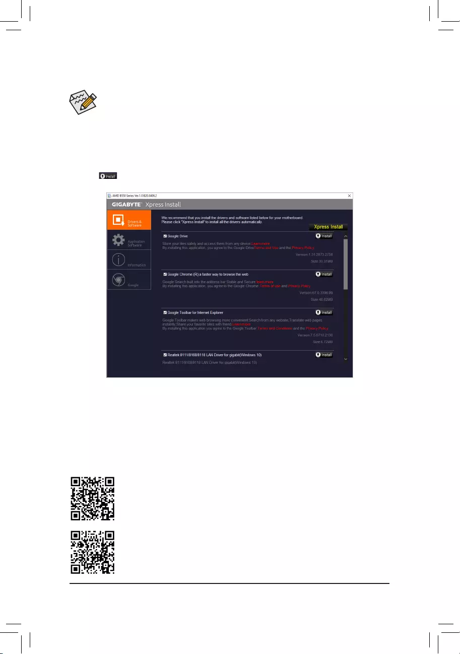
•Before installing the drivers, rst install the operating system.
•After installing the operating system, insert the motherboard driver disc into your optical drive. Click
on the message «Tap to choose what happens with this disc» on the top-right corner of the screen
and select «Run Run.exe.» (Or go to My Computer, double-click the optical drive and execute the
Run.exe program.)
«Xpress Install» will automatically scan your system and then list all of the drivers that are recommended to
install. You can click the Xpress Install button and «Xpress Install» will install all of the selected drivers. Or click
the arrow icon to individually install the drivers you need.
Please visit GIGABYTE’s website for more software information.
3-2 Drivers Installation
Please visit GIGABYTE’s website for more troubleshooting information.
— 39 —
Regulatory Notices
CAUTION:
The manufacturer is not responsible for any interference caused by unauthorized modications and/or use of unauthorized antennas. Such changes
and/or modications not expressly approved by the party responsible for compliance of this device could void the user’s authority to operate the
equipment.
RF exposure statement / Antenna Use
Further RF exposure reduction can be achieved if the product can be kept as far as possible from the user body or set the device to lower output
power if such function is available.
•Do not touch or move antenna while the unit is transmitting or receiving.
•Do not hold any component containing the radio such that the antenna is very close or touching any exposed parts of the body, especially the face
or eyes, while transmitting.
•Do not operate the radio or attempt to transmit data unless the antenna is connected; this behavior may cause damage to the radio.
United States of America, Federal Communications Commission Statement
Supplier’s Declaration of Conformity
47 CFR § 2.1077 Compliance Information
Product Name: Motherboard
Trade Name: GIGABYTE
Model Number: B550 AORUS ELITE AX V2/B550 AORUS ELITE V2
Responsible Party – U.S. Contact Information: G.B.T. Inc.
Address: 17358 Railroad street, City Of Industry, CA91748
Tel.: 1-626-854-9338
Internet contact information: https://www.gigabyte.com
FCC Compliance Statement:
This device complies with Part 15 of the FCC Rules, Subpart B, Unintentional Radiators.
Operation is subject to the following two conditions: (1) This device may not cause harmful interference, and (2) this
device must accept any interference received, including interference that may cause undesired operation.
This equipment has been tested and found to comply with the limits for a
Class B digital device, pursuant to Part 15 of the FCC Rules. These limits
are designed to provide reasonable protection against harmful interference
in a residential installation. This equipment generates, uses and can radiate
radio frequency energy and, if not installed and used in accordance with
manufacturer’s instructions, may cause harmful interference to radio
communications. However, there is no guarantee that interference will
not occur in a particular installation. If this equipment does cause harmful
interference to radio or television reception, which can be determined by
turning the equipment off and on, the user is encouraged to try to correct
the interference by one or more of the following measures:
•Reorient or relocate the receiving antenna.
•Increase the separation between the equipment and receiver.
•Connect the equipment to an outlet on a circuit different from that to
which the receiver is connected.
•Consult the dealer or an experienced radio/TV technician for help.
Notice for 5GHz
Operations in the 5.15-5.25GHz band are restricted to indoor usage
only. (For 5GHz only)
Canadian Department of Communications Statement
This digital apparatus does not exceed the Class B limits for radio
noise emissions from digital apparatus set out in the Radio Interference
Regulations of the Canadian Department of Communications. This class
B digital apparatus complies with Canadian ICES-003.
Avis de conformité à la réglementation d’Industrie Canada
Cet appareil numérique de la classe B est conforme à la norme NMB-
003 du Canada.
Canada-Industry Canada (IC) Regulatory statement
This device complies with Canadian RSS-210.
This device complies with Industry Canada license-exempt RSS
standard(s). Operation is subject to the following two conditions: (1) this
device may not cause interference, and (2) this device must accept any
interference, including interference that may cause undesired operation
of the device.
Cet appareil se conforme aux normesCanada d’Industrie de RSS
permis-exempt. L’utilisation est assujetti aux deux conditions suivantes:
(1) cet appareil ne peut pas causer d’interférences, et (2) cet appareil doit
accepter des interférences, y compris des interférences qui peuvent causer
desopérations non désirées de l’appareil.
Caution: When using IEEE 802.11a wireless LAN, this product is restricted
to indoor use due to its operation in the 5.15-to 5.25-GHz frequency
range. Industry Canada requires this product to be used indoors for the
frequency range of 5.15 GHz to 5.25 GHz to reduce the potential for
harmful interference to co-channel mobile satellite systems. High power
radar is allocated as the primary user of the 5.25-to 5.35-GHz and 5.65 to
5.85-GHz bands. These radar stations can cause interference with and/or
damage to this device. The maximum allowed antenna gain for use with
this device is 6dBi in order to comply with the E.I.R.P limit for the 5.25-to
5.35 and 5.725 to 5.85 GHz frequency range in point-to-point operation. To
comply with RF exposure requirements all antennas should be located at a
minimum distance of 20cm, or the minimum separation distance allowed
by the module approval, from the body of all persons.
Attention: l’utilisation d’un réseau sans l IEEE802.11a est restreinte à
une utilisation en intérieur à cause du fonctionnement dansla bande de
fréquence 5.15-5.25 GHz. Industry Canada requiert que ce produit soit
utilisé à l’intérieur des bâtiments pour la bande de fréquence 5.15-5.25
GHz an de réduire les possibilités d’interférences nuisibles aux canaux
co-existants des systèmes de transmission satellites. Les radars de
puissances ont fait l’objet d’une allocation primaire de fréquences dans
les bandes 5.25-5.35 GHz et 5.65-5.85 GHz. Ces stations radar peuvent
créer des interférences avec ce produit et/ou lui être nuisible. Le gain
d’antenne maximum permissible pour une utilisation avec ce produit
est de 6 dBi an d’être conforme aux limites de puissance isotropique
rayonnée équivalente (P.I.R.E.) applicable dans les bandes 5.25-5.35 GHz
et 5.725-5.85 GHz en fonctionnement point-à-point. Pour se conformer aux
conditions d’exposition de RF toutes les antennes devraient être localisées
à une distance minimum de 20 cm, ou la distance de séparation minimum
permise par l’approbation du module, du corps de toutes les personnes.»
— 40 —
Radiation Exposure Statement:
Under Industry Canada regulations, this radio transmitter may only operate
using an antenna of a type and maximum (or lesser) gain approved for
the transmitter by Industry Canada. To reduce potential radio interference
to other users, the antenna type and its gain should be so chosen that
the equivalent isotopically radiated power (e.i.r.p.) is not more than that
necessary for successful communication.
Selon les règlements de Canada d’Industrie, cet émetteur de radio peut
seulement fonctionner en utilisant une antenne du typeet de gain maximum
(ou moindre) que le gainapprouvé pour l’émetteur par Canada d’Industrie.
Pour réduire lesinterférencesradio potentiellesavec les autres utilisateurs,
le type d’antenne et son gain devraient êtrechoisis de façon à ce que la
puissance isotrope rayonnée équivalente(P.I.R.E.)ne soit pas supérieure
à celle qui estnécessaire pour une communication réussie.
European Union (EU) CE Declaration of Conformity
This device complies with the following directives: Electromagnetic
Compatibility Directive 2014/30/EU, Radio Equipment Directive (RED)
2014/53/EU, Low-voltage Directive 2014/35/EU, RoHS directive (recast)
2011/65/EU & the 2015/863 Statement.
This product has been tested and found to comply with all essential
requirements of the Directives
European Union (EU) RoHS (recast) Directive 2011/65/EU & the
European Commission Delegated Directive (EU) 2015/863 Statement
GIGABYTE products have not intended to add and safe from hazardous
substances (Cd, Pb, Hg, Cr+6, PBDE, PBB, DEHP, BBP, DBP and DIBP).
The parts and components have been carefully selected to meet RoHS
requirement. Moreover, we at GIGABYTE are continuing our efforts to
develop products that do not use internationally banned toxic chemicals.
European Union (EU) Community Waste Electrical & Electronic
Equipment (WEEE) Directive Statement
GIGABYTE will fulll the national laws as interpreted from the 2012/19/
EU WEEE (Waste Electrical and Electronic Equipment) (recast) directive.
The WEEE Directive species the treatment, collection, recycling and
disposal of electric and electronic devices and their components. Under
the Directive, used equipment must be marked, collected separately, and
disposed of properly.
WEEE Symbol Statement
The symbol shown below is on the product or on its
packaging, which indicates that this product must not be
disposed of with other waste. Instead, the device should be
taken to the waste collection centers for activation of the
treatment, collection, recycling and disposal procedure.
For more information about where you can drop off your waste equipment
for recycling, please contact your local government ofce, your household
waste disposal service or where you purchased the product for details of
environmentally safe recycling.
End of Life Directives-Recycling
The symbol shown below is on the product or on its packaging,
which indicates that this product must not be disposed of with
other waste. Instead, the device should be taken to the waste
collection centers for activation of the treatment, collection,
recycling and disposal procedure.
Déclaration de Conformité aux Directives de l’Union européenne (UE)
Cet appareil portant la marque CE est conforme aux directives de l’UE
suivantes: directive Compatibilité Electromagnétique 2014/30/UE, directive
RED (équipements radioélectriques) 2014/53/UE, directive Basse Tension
2014/35/UE et directive RoHS II 2011/65/UE. La conformité à ces directives
est évaluée sur la base des normes européennes harmonisées applicables.
European Union (EU) CE-Konformitätserklärung
Dieses Produkte mit CE-Kennzeichnung erfüllen folgenden EU-Richtlinien:
EMV-Richtlinie 2014/30/EU, Richtlinie RED (Funkanlagen) 2014/53/EU,
Niederspannungsrichtlinie 2014/30/EU und RoHS-Richtlinie 2011/65/
EU erfüllt. Die Konformität mit diesen Richtlinien wird unter Verwendung
der entsprechenden Standards zurEuropäischen Normierung beurteilt.
CE declaração de conformidade
Este produto com a marcação CE estão em conformidade com das
seguintes Diretivas UE: Diretiva de equipamentos de rádio 2014/53/EU,
Diretiva Baixa Tensão 2014/35/EU; Diretiva CEM 2014/30/EU; Diretiva
RSP 2011/65/UE. A conformidade com estas diretivas é vericada
utilizando as normas europeias harmonizadas.
CE Declaración de conformidad
Este producto que llevan la marca CE cumplen con las siguientes
Directivas de la Unión Europea: Directiva EMC 2014/30/EU, Directiva de
equipos radioeléctricos 2014/53/EU, Directiva de bajo voltaje 2014/35/EU,
Directiva RoHS (recast) 2011/65/EU. El cumplimiento de estas directivas
se evalúa mediante las normas europeas armonizadas.
Dichiarazione di conformità CE
Questo prodotto è conforme alle seguenti direttive: Direttiva sulla
compatibilità elettromagnetica 2014/30/UE, Direttiva sulle apparecchiature
radio (RED) 2014/53/UE, Direttiva sulla bassa tensione 2014/35/UE,
Direttiva RoHS (rifusione) 2011/65/UE. Questo prodotto è stato testato e
trovato conforme a tutti i requisiti essenziali delle Direttive.
Contact point for EU based customers
G.B.T. Technology Trading GmbH
Am Stadtrand 63, 22047 Hamburg, Germany
tel: +49-40-25 33 040
— 41 —
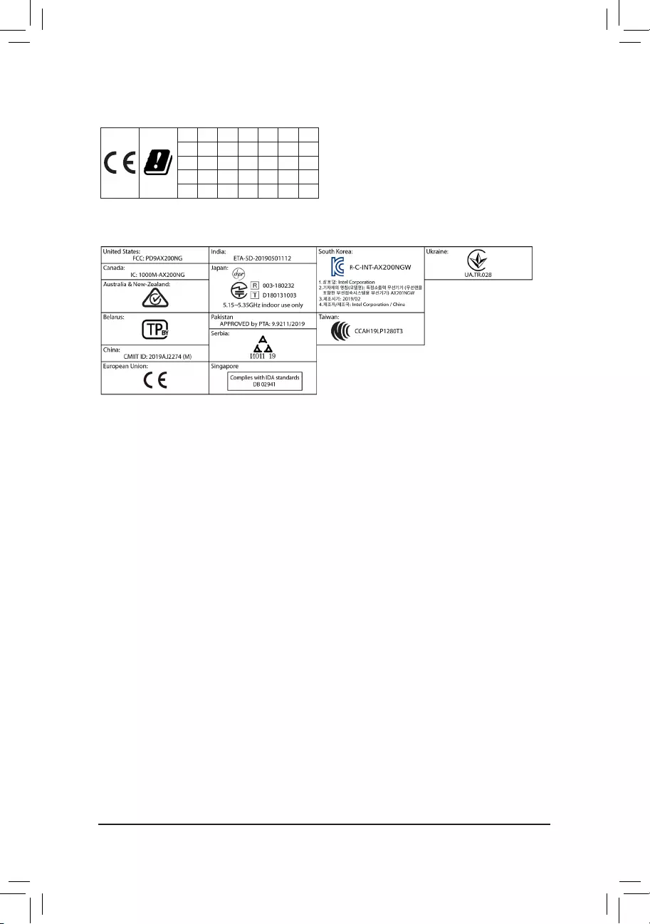
European Community Directive RED Directive Compliance Statement:
This equipment is suitable for home and ofce use in all the European Community Member States and EFTA Member States.
The low band 5.15 -5.35 GHz is for indoor use only for the countries listed in the table below:
AT BE BG CH CY CZ DE
DK EE EL ES FI FR HR
HU IE IS IT LI LT LU
LV MT NL PL PT RO SE
SI SK TR UK
Wireless module country approvals:
Wireless module model name: AX200NGW
Wireless module manufacturer: Intel® Corporation
Korea Wireless Statement:
5.15 — 5.35 GHz 대역에서의 작동은 실내로。
Japan Wireless Statement:
5.15 GHz帯 ~ 5.35 GHz帯: 屋内のみの使用。
Taiwan NCC Wireless Statements / 無線設備警告聲明:
低功率電波輻射性電機管理辦法
第十二條: 經型式認證合格之低功率射頻電機,非經許可,公司、商號或使用者均不得擅自變更頻率、加大功率或變更原設
計之特性及功能。
第十四條: 低功率射頻電機之使用不得影響飛航安全及干擾合法通信;經發現有干擾現象時,應立即停用,並改善至無干擾
時方得繼續使用。前項合法通信,指依電信法規定作業之無線電通信。低功率射頻電機須忍受合法通信或工業、
科學及醫療用電波輻射性電機設備之干擾。
在5.25-5.35秭赫頻帶內操作之無線資訊傳輸設備,限於室內使用。
— 42 —

— 43 —
Contact Us
GIGA-BYTE TECHNOLOGY CO., LTD.
Address: No.6, Baoqiang Rd., Xindian Dist., New Taipei City 231, Taiwan
TEL: +886-2-8912-4000, FAX: +886-2-8912-4005
Tech. and Non-Tech. Support (Sales/Marketing) : https://esupport.gigabyte.com
WEB address (English): https://www.gigabyte.com
WEB address (Chinese): https://www.gigabyte.com/tw
•GIGABYTE eSupport
To submit a technical or non-technical (Sales/Marketing) question, please link to:
https://esupport.gigabyte.com
— 44 —