-
Драйверы
24
-
Инструкции по эксплуатации
26
Языки:

Gigabyte GA-X58A-UD3R инструкция по эксплуатации
(72 страницы)
- Языки:Венгерский, Греческий, Испанский, Итальянский, Немецкий, Польский, Португальский, Русский, Турецкий, Французский, Чешский
-
Тип:
PDF -
Размер:
18.6 MB -
Описание:
Installation Guidebook


На NoDevice можно скачать инструкцию по эксплуатации для Gigabyte GA-X58A-UD3R. Руководство пользователя необходимо для ознакомления с правилами установки и эксплуатации Gigabyte GA-X58A-UD3R. Инструкции по использованию помогут правильно настроить Gigabyte GA-X58A-UD3R, исправить ошибки и выявить неполадки.
-
Contents
-
Table of Contents
-
Troubleshooting
-
Bookmarks
Quick Links
GA-X58A-UD3R
LGA1366 socket motherboard for Intel
Core
i7 processor family
®
™
User’s Manual
Rev. 2001
12ME-X58AU3R-2001R
Related Manuals for Gigabyte GA-X58A-UD3R
Summary of Contents for Gigabyte GA-X58A-UD3R
-
Page 1
GA-X58A-UD3R LGA1366 socket motherboard for Intel Core i7 processor family ® ™ User’s Manual Rev. 2001 12ME-X58AU3R-2001R… -
Page 3: Identifying Your Motherboard Revision
GIGABYTE’s prior written permission. Documentation Classifications In order to assist in the use of this product, GIGABYTE provides the following types of documentations: For quick set-up of the product, read the Quick Installation Guide included with the product.
-
Page 4: Table Of Contents
Table of Contents Box Contents ……………………6 Optional Items …………………….6 GA-X58A-UD3R Motherboard Layout …………….7 GA-X58A-UD3R Motherboard Block Diagram …………..8 Chapter 1 Hardware Installation ………………9 Installation Precautions ………………. 9 1-2 Product Specifications ………………. 10 Installing the CPU and CPU Cooler…………… 13 1-3-1 Installing the CPU ………………..13 1-3-2 Installing the CPU Cooler ………………15 Installing the Memory ………………
-
Page 5
Hard Drive (X.H.D) …………….84 Chapter 5 Appendix ………………….85 5-1 Configuring SATA Hard Drive(s) …………..85 5-1-1 Configuring Intel ICH10R SATA Controllers …………85 5-1-2 Configuring JMicron JMB362/GIGABYTE SATA2 SATA Controller …..93 5-1-3 Configuring Marvell 9128 SATA Controller …………99 5-1-4 Making a SATA RAID/AHCI Driver Diskette …………104 5-1-5 Installing the SATA RAID/AHCI Driver and Operating System ……106 5-2 Configuring Audio Input and Output ………….119… -
Page 6: Box Contents
Box Contents GA-X58A-UD3R motherboard Motherboard driver disk User’s Manual Quick Installation Guide One IDE cable Four SATA cables I/O Shield One 2-Way SLI bridge connector One 3-Way SLI bridge connector • The box contents above are for reference only and the actual items shall depend on the product package you obtain. The box contents are subject to change without notice.
-
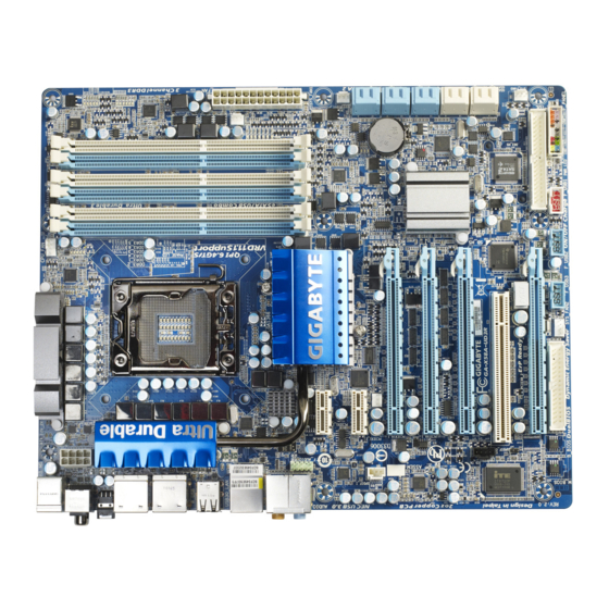
Page 7: Ga-X58A-Ud3R Motherboard Layout
SATA2_4 Intel ICH10R ® GSATA3_7 PCIEX16_2 GSATA3_6 CD_IN GSATA2_9 GSATA2_8 SYS_FAN3 T.I. TSB43AB23 GIGABYTE SATA2 F_1394 PCIEX8_2 M_BIOS F_PANEL B_BIOS SYS_FAN2 F_USB3 F_USB2 F_USB1 (Note) Due to a hardware limitation, the PCIEX1_1 slot can only accommodate a shorter PCI Express x1 expansion card.
-
Page 8: Ga-X58A-Ud3R Motherboard Block Diagram
(100 MHz) Intel ICH10R ® JMicron JMB362 2 PCI Express x1 12 USB 2.0/1.1 (Note) 2 SATA 3Gb/s 2 SATA 3Gb/s GIGABYTE SATA2 ATA-133/100/66/33 IDE Channel PCI Bus Floppy T.I. TSB43AB23 IT8720 CODEC PS/2 KB/Mouse 3 IEEE 1394a 1 PCI…
-
Page 9: Chapter 1 Hardware Installation
Chapter 1 Hardware Installation Installation Precautions The motherboard contains numerous delicate electronic circuits and components which can become damaged as a result of electrostatic discharge (ESD). Prior to installation, carefully read the user’s manual and follow these procedures: • Prior to installation, do not remove or break motherboard S/N (Serial Number) sticker or warranty sticker provided by your dealer.
-
Page 10: Product Specifications
Support for DDR3 2200/1333/1066/800 MHz memory modules Support for non-ECC memory modules Support for Extreme Memory Profile (XMP) memory modules (Go to GIGABYTE’s website for the latest supported memory speeds and memory modules.) Audio Realtek ALC889 codec High Definition Audio 2/4/5.1/7.1-channel Support for Dolby…
-
Page 11
Storage Interface JMicron JMB362 chip: 2 x eSATA 3Gb/s connectors (eSATA/USB Combo) on the back panel sup- porting up to 2 SATA 3Gb/s devices Support for SATA RAID 0, RAID 1, and JBOD iTE IT8720 chip: 1 x floppy disk drive connector supporting up to 1 floppy disk drive South Bridge: … -
Page 12
I/O Controller iTE IT8720 chip Hardware Monitor System voltage detection CPU/North Bridge temperature detection CPU/System/Power fan speed detection CPU overheating warning CPU fan fail warning CPU/System fan speed control (Note 4) BIOS 2 x 16 Mbit flash Use of licensed AWARD BIOS … -
Page 13: Installing The Cpu And Cpu Cooler
Read the following guidelines before you begin to install the CPU: • Make sure that the motherboard supports the CPU. (Go to GIGABYTE’s website for the latest CPU support list.) • Always turn off the computer and unplug the power cord from the power outlet before installing the CPU to prevent hardware damage.
-
Page 14
B. Follow the steps below to correctly install the CPU into the motherboard CPU socket. Before installing the CPU, make sure to turn off the computer and unplug the power cord from the power outlet to prevent damage to the CPU. CPU Socket Lever Step 1: Step 2:… -
Page 15: Installing The Cpu Cooler
1-3-2 Installing the CPU Cooler Follow the steps below to correctly install the CPU cooler on the motherboard. (The following procedure uses Intel boxed cooler as the example cooler.) ® Male Push Direction of the Arrow Sign on the Male Push The Top of Female Push Pin…
-
Page 16: Installing The Memory
• Make sure that the motherboard supports the memory. It is recommended that memory of the same capacity, brand, speed, and chips be used. (Go to GIGABYTE’s website for the latest supported memory speeds and memory modules.) • Always turn off the computer and unplug the power cord from the power outlet before installing the memory to prevent hardware damage.
-
Page 17: Installing A Memory
1-4-2 Installing a Memory Before installing a memory module, make sure to turn off the computer and unplug the power cord from the power outlet to prevent damage to the memory module. DDR3 and DDR2 DIMMs are not compatible to each other or DDR DIMMs. Be sure to install DDR3 DIMMs on this motherboard.
-
Page 18: Installing An Expansion Card
Installing an Expansion Card Read the following guidelines before you begin to install an expansion card: • Make sure the motherboard supports the expansion card. Carefully read the manual that came with your expansion card. • Always turn off the computer and unplug the power cord from the power outlet before installing an expansion card to prevent hardware damage.
-
Page 19: Setup Of Ati Crossfirex ™ /Sli Configuration
Setup of ATI CrossFireX /SLI Configuration ™ A. System Requirements — The 2-Way CrossFireX/SLItechnology currently supports Windows XP, Windows Vista, and Windows 7 operating systems — The 3-Way CrossFireX/SLI technology currectly supports Windows Vista and Windows 7 operating systems only — A CrossFireX/SLI-supported motherboard with two/three PCI Express x16 slots and correct driver — Two/three CrossFireX/SLI-ready graphics cards of identical brand and chip and correct driver — One/two CrossFire…
-
Page 20: Back Panel Connectors
Back Panel Connectors CMOS PS/2 Keyboard and PS/2 Mouse Port Use the upper port (green) to connect a PS/2 mouse and the lower port (purple) to connect a PS/2 key- board. Optical S/PDIF Out Connector This connector provides digital audio out to an external audio system that supports digital optical audio. Before using this feature, ensure that your audio system provides an optical digital audio in connector.
-
Page 21
USB 3.0/2.0 Port The USB 3.0 port supports the USB 3.0 specification and is compatible to the USB 2.0/1.1 specification. Use this port for USB devices such as a USB keyboard/mouse, USB printer, USB flash drive and etc. Center/Subwoofer Speaker Out Jack (Orange) Use this audio jack to connect center/subwoofer speakers in a 5.1/7.1-channel audio configuration. Rear Speaker Out Jack (Black) Use this audio jack to connect rear speakers in a 7.1-channel audio configuration. Side Speaker Out Jack (Gray) Use this audio jack to connect side speakers in a 4/5.1/7.1-channel audio configuration. Line In Jack (Blue) The default line in jack. Use this audio jack for line in devices such as an optical drive, walkman, etc. Line Out Jack (Green) The default line out jack. -
Page 22: Onboard Leds And Switches
Onboard LEDs and Switches Overvoltage LEDs This motherboard contains 4 sets of overvoltage LEDs which indicate the overvoltage level of the CPU, memory, North Bridge, and South Bridge. CPU Voltage DDR Voltage Off: Normal condition Off: Normal condition L1: Level 1 (Slight, green) L1: Level 1 (Slight, green) L2: Level 2 (Moderate, yellow) L2: Level 2 (Moderate, yellow)
-
Page 23
PHASE LED The number of lighted LEDs indicates the CPU loading. The higher the CPU loading, the more the number of lighted LEDs. To enable the Phase LED display function, please first enable Dynamic Energy Saver 2. Refer to Chapter 4, «Dynamic Energy Saver 2,» for more details. NB PHASE LED The number of lighted LEDs indicates the North Bridge loading. The higher the North Bridge loading, the more the number of lighted LEDs. -
Page 24: Internal Connectors
Internal Connectors ATX_12V_2X GSATA3_6/7 CPU_FAN F_PANEL SYS_FAN1/2/3 F_AUDIO PWR_FAN CD_IN NB_FAN SPDIF_I SPDIF_O F_USB1/F_USB2/F_USB3 SATA2_0/1/2/3/4/5 F_1394 GSATA2_8/9 Read the following guidelines before connecting external devices: • First make sure your devices are compliant with the connectors you wish to connect. • Before installing the devices, be sure to turn off the devices and your computer.
-
Page 25
1/2) ATX_12V_2X/ATX (2×4 12V Power Connector and 2×12 Main Power Connector) With the use of the power connector, the power supply can supply enough stable power to all the com- ponents on the motherboard. Before connecting the power connector, first make sure the power supply is turned off and all devices are properly installed. The power connector possesses a foolproof design. Connect the power supply cable to the power connector in the correct orientation. -
Page 26
3/4/5) CPU_FAN/SYS_FAN1/SYS_FAN2/SYS_FAN3/PWR_FAN (Fan Headers) The motherboard has a 4-pin CPU fan header (CPU_FAN), a 4-pin (SYS_FAN2) and two 3-pin (SYS_ FAN1/SYS_FAN3) system fan headers, and a 3-pin power fan header (PWR_FAN). Most fan headers possess a foolproof insertion design. When connecting a fan cable, be sure to connect it in the correct orientation (the black connector wire is the ground wire). -
Page 27: Fdd (Floppy Disk Drive Connector)
7) FDD (Floppy Disk Drive Connector) This connector is used to connect a floppy disk drive. The types of floppy disk drives supported are: 360 KB, 720 KB, 1.2 MB, 1.44 MB, and 2.88 MB. Before connecting a floppy disk drive, be sure to locate pin 1 of the connector and the floppy disk drive cable. The pin 1 of the cable is typically designated by a stripe of different color. For purchasing the optional floppy disk drive cable, please contact the local dealer.
 IDE (IDE Connector) The IDE connector supports up to two IDE devices such as hard drives and optical drives. Before attach- ing the IDE cable, locate the foolproof groove on the connector.
 -
Page 28
10) GSATA2_8/9 (SATA 3Gb/s Connectors, Controlled by GIGABYTE SATA2) The SATA connectors conform to SATA 3Gb/s standard and are compatible with SATA 1.5Gb/s standard. Each SATA connector supports a single SATA device. The GIGABYTE SATA2 controller supports RAID 0, DEBUG PORT RAID 1, and JBOD. Refer to Chapter 5, «Configuring SATA Hard Drive(s),» for instructions on configuring… -
Page 29
11) GSATA3_6/7 (SATA 6Gb/s Connectors, Controlled by Marvell 9128) The SATA connectors conform to SATA 6Gb/s standard and are compatible with SATA 3Gb/s and SATA 1.5Gb/s standards. Each SATA connector supports a single SATA device. The Marvell 9128 supports RAID 0 and RAID 1. Refer to Chapter 5, «Configuring SATA Hard Drive(s),» for instructions on configur- ing a RAID array. -
Page 30: F_Panel Front Panel Header
13) F_PANEL (Front Panel Header) Connect the power switch, reset switch, speaker, chassis intrusion switch/sensor and system status indicator on the chassis to this header according to the pin assignments below. Note the positive and negative pins before connecting the cables. Message/Power/ Power Speaker…
-
Page 31: Cd In Connector
14) F_AUDIO (Front Panel Audio Header) The front panel audio header supports Intel High Definition audio (HD) and AC’97 audio. You may connect your chassis front panel audio module to this header. Make sure the wire assignments of the module con- nector match the pin assignments of the motherboard header. Incorrect connection between the module connector and the motherboard header will make the device unable to work or even damage it. For HD Front Panel Audio: For AC’97 Front Panel Audio: Pin No. Definition…
-
Page 32
16) SPDIF_I (S/PDIF In Header) This header supports digital S/PDIF In and can connect to an audio device that supports digital audio out via an optional S/PDIF In cable. For purchasing the optional S/PDIF In cable, please contact the local dealer. -
Page 33
18) F_USB1/F_USB2/F_USB3 (USB Headers) The headers conform to USB 2.0/1.1 specification. Each USB header can provide two USB ports via an optional USB bracket. For purchasing the optional USB bracket, please contact the local dealer. Pin No. Definition Power (5V) Power (5V) USB DX- USB DY- USB DX+ USB DY+ No Pin When the system is in S4/S5 mode, only the USB ports routed to the F_USB1 header can sup- port the ON/OFF Charge function. -
Page 34
Hardware Installation — 34 -… -
Page 35: Chapter 2 Bios Setup
To see more advanced BIOS Setup menu options, you can press <Ctrl> + <F1> in the main menu of the BIOS Setup program. To upgrade the BIOS, use either the GIGABYTE Q-Flash or @BIOS utility. Q-Flash allows the user to quickly and easily upgrade or back up BIOS without entering the operating •…
-
Page 36: Startup Screen
Startup Screen The following screens may appear when the computer boots. A. The LOGO Screen (Default) Function Keys B. The POST Screen Award Modular BIOS v6.00PG, An Energy Star Ally Copyright (C) 1984-2010, Award Software, Inc. X58A-UD3R F6a Motherboard Model BIOS Version Function Keys <DEL>: BIOS Setup <F9>: XpressRecovery2 <F12>: Boot Menu <End>: Qflash…
-
Page 37: The Main Menu
The Main Menu Once you enter the BIOS Setup program, the Main Menu (as shown below) appears on the screen. Use ar- row keys to move among the items and press <Enter> to accept or enter a sub-menu. (Sample BIOS Version: F6a) CMOS Setup Utility-Copyright (C) 1984-2010 Award Software MB Intelligent Tweaker(M.I.T.) Load Fail-Safe Defaults…
-
Page 38: Integrated Peripherals
The Functions of the <F11> and <F12> keys (For the Main Menu Only) F11: Save CMOS to BIOS This function allows you to save the current BIOS settings to a profile. You can create up to 8 profiles (Profile 1-8) and name each profile. First enter the profile name (to erase the default profile name, use the SPACE key) and then press <Enter> to complete. F12: Load CMOS from BIOS If your system becomes unstable and you have loaded the BIOS default settings, you can use this function to load the BIOS settings from a profile created before, without the hassles of reconfiguring the BIOS settings. First select the profile you wish to load, then press <Enter> to complete.
-
Page 39: Mb Intelligent Tweaker(M.i.t.)
MB Intelligent Tweaker(M.I.T.) CMOS Setup Utility-Copyright (C) 1984-2010 Award Software MB Intelligent Tweaker(M.I.T.) Item Help CPU Clock Ratio [22X] (Note 1) Menu Level CPU Frequency 2.93GHz(133×22) Advanced CPU Features [Press Enter] QPI Clock Ratio [Auto] QPI Link Speed 4.8GHz …
-
Page 40: Cpu Frequency
CMOS Setup Utility-Copyright (C) 1984-2010 Award Software MB Intelligent Tweaker(M.I.T.) Item Help CPU Vcore 1.21875V [Auto] Menu Level QPI/Vtt Voltage 1.150V [Auto] IOH Core 1.100V [Auto] DRAM Voltage 1.500V [Auto] Advanced Voltage Control [Press Enter] higf : Move Enter: Select +/-/PU/PD: Value F10: Save…
-
Page 41
CPU Cores Enabled (Note) Allows you to determine whether to enable all CPU cores. Enables all CPU cores. (Default) Enables only one CPU core. Enables only two CPU cores. Enables only three CPU cores. CPU Multi-Threading (Note) Allows you to determine whether to enable multi-threading technology when using an Intel CPU that supports this function. -
Page 42
******** UnCore & QPI Features ******** CMOS Setup Utility-Copyright (C) 1984-2010 Award Software UnCore & QPI Features Item Help QPI Clock Ratio [Auto] Menu Level QPI Link Speed 4.8GHz Uncore Clock Ratio [Auto] Uncore Frequency 2133MHz Isochronous Support [Enabled] higf : Move Enter: Select +/-/PU/PD: Value… -
Page 43
>>>>> Standard Clock Control Base Clock(BCLK) Control Enables or disables the control of CPU base clock. Enabled will allow the BCLK Frequency(Mhz) item below to be configurable. Note: If your system fails to boot after overclocking, please wait for 20 seconds to allow for automated system reboot, or clear the CMOS values to reset the board to default values. (Default: Disabled) BCLK Frequency(Mhz) Allows you to manually set the CPU base clock. -
Page 44
******** Advanced DRAM Features ******** CMOS Setup Utility-Copyright (C) 1984-2010 Award Software Advanced DRAM Features Item Help Performance Enhance [Turbo] Menu Level Extreme Memory Profile (X.M.P.) [Disabled] (Note) System Memory Multiplier (SPD) [Auto] Memory Frequency (Mhz) 1066 1066 DRAM Timing Selectable (SPD) [Auto] Profile DDR Voltage 1.5V… -
Page 45: Channel Interleaving
Channel Interleaving Options are: Auto (default), 1~6. Rank Interleaving Options are: Auto (default), 1~4. >>>>> Channel A/B/C Timing Settings CMOS Setup Utility-Copyright (C) 1984-2010 Award Software Channel A Timing Settings Item Help >>>>> Channel A Standard Timing Control Menu Level x CAS Latency Time Auto x tRCD…
-
Page 46
tWTP Options are: Auto (default), 1~31. Options are: Auto (default), 1~10. tRFC Options are: Auto (default), 1~255. tRTP Options are: Auto (default), 1~15. tFAW Options are: Auto (default), 1~63. Command Rate(CMD) Options are: Auto (default), 1~3. >>>>> Channel A/B/C Misc Timing Control B2B CAS Delay Options are: Auto (default), 1~31. -
Page 47
>>>>> Channel A/B/C Writes Followed by Writes Different DIMMs Options are: Auto (default), 1~8. Different Ranks Options are: Auto (default), 1~8. On The Same Rank Options are: Auto (default), 1~2. ******** Advanced Voltage Control ******** CMOS Setup Utility-Copyright (C) 1984-2010 Award Software Advanced Voltage Control Item Help Voltage Types… -
Page 48
>>>>> CPU Load-Line Calibration Enables or disables Load-Line Calibration. This item allows you to adjust Vdroop at different levels. Enabling Load-Line Calibration may keep the CPU voltage more constant under light and heavy CPU load. Standard Disables Load-Line Calibration and sets VDroop following Intel specifications. (Default) Level 1 Enables Load-Line Calibration and slightly adjusts VDroop. Level 2 Enables Load-Line Calibration and moderately adjusts VDroop. -
Page 49: Standard Cmos Features
Standard CMOS Features CMOS Setup Utility-Copyright (C) 1984-2010 Award Software Standard CMOS Features Item Help Date (mm:dd:yy) Mon, Mar 29 2010 Menu Level Time (hh:mm:ss) 22:31:24 IDE Channel 0 Master [None] IDE Channel 0 Slave [None] IDE Channel 1 Master [None] …
-
Page 50
If no IDE/SATA devices are used, set this item to None so the system will skip • None the detection of the device during the POST for faster system startup. Allows you to manually enter the specifications of the hard drive when the hard • Manual drive access mode is set to CHS. Access Mode Sets the hard drive access mode. -
Page 51: Advanced Bios Features
Advanced BIOS Features CMOS Setup Utility-Copyright (C) 1984-2010 Award Software Advanced BIOS Features Item Help Hard Disk Boot Priority [Press Enter] Menu Level Quick Boot [Disabled] First Boot Device [Floppy] Second Boot Device [Hard Disk] Third Boot Device [CDROM] Password Check [Setup]…
-
Page 52: Init Display First
Allows you to set a delay time for the BIOS to initialize the hard drive as the system boots up. The ad- justable range is from 0 to 15 seconds. (Default: 0) Full Screen LOGO Show Allows you to determine whether to display the GIGABYTE Logo at system startup. Disabled displays normal POST message. (Default: Enabled) Backup BIOS Image to HDD Allows the system to copy the BIOS image file to the hard drive. If the system BIOS is corrupted, it will…
-
Page 53: Integrated Peripherals
Enables or disables the X.H.D function for the SATA controllers integrated in the Intel ICH10R South Bridge. When set to Enabled, the ICH SATA Control Mode item below will be set to RAID(XHD) au- tomatically. For details on using the GIGABYTE X.H.D utility, refer to Chaper 4, «eXtreme Hard Drive (X.H.D).» (Default: Disabled)
-
Page 54: Usb Keyboard Function
RAID(XHD) Enables RAID for the SATA controllers. AHCI Configures the SATA controllers to AHCI mode. Advanced Host Controller Interface (AHCI) is an interface specification that allows the storage driver to enable advanced Serial ATA features such as Native Command Queuing and hot plug. SATA Port0-3 Native Mode (Intel ICH10R South Bridge) Specifies the operating mode of the integrated SATA controllers. Disabled Allows the SATA controllers to operate in Legacy IDE mode. In Legacy mode the SATA controllers use dedicated IRQs that cannot be shared with other device.
-
Page 55: Onboard Lan Boot Rom
SMART LAN (LAN Cable Diagnostic Function) CMOS Setup Utility-Copyright (C) 1984-2010 Award Software SMART LAN Item Help Start detecting at Port..Menu Level Part1-2 Status = Open / Length = Part3-6 Status = Open / Length = Part4-5 Status = Open / Length = Part7-8 Status = Open / Length = higf : Move Enter: Select…
-
Page 56
Allows you to configure RAID for the Marvell 9128 SATA controller. Refer to Chapter 5, «Configuring SATA Hard Drive(s),» for instructions on configuring a RAID array. GSATA 8_9/IDE Controller (GIGABYTE SATA2 Chip, IDE and GSATA2_8/9 Connectors) Enables or disables the IDE and SATA controller integrated in the GIGABYTE SATA2 chip. (Default: En- abled) GSATA 8_9/IDE Ctrl Mode (GIGABYTE SATA2 Chip, IDE and GSATA2_8/9 Connectors) Enables or disables RAID for the SATA controller integrated in the GIGABYTE SATA2 chip or configures the SATA controller to AHCI mode. -
Page 57: Power Management Setup
Power Management Setup CMOS Setup Utility-Copyright (C) 1984-2010 Award Software Power Management Setup Item Help ACPI Suspend Type [S3(STR)] Menu Level Soft-Off by PWR-BTTN [Instant-Off] PME Event Wake Up [Enabled] Power On by Ring [Enabled] Resume by Alarm [Disabled] Date (of Month) Alarm Everyday Time (hh:mm:ss) Alarm…
-
Page 58
Resume by Alarm Determines whether to power on the system at a desired time. (Default: Disabled) If enabled, set the date and time as following: Date (of Month) Alarm: Turn on the system at a specific time on each day or on a specific day in a month. Time (hh: mm: ss) Alarm: Set the time at which the system will be powered on automatically. Note: When using this function, avoid inadequate shutdown from the operating system or removal of the AC power, or the settings may not be effective. -
Page 59: Pc Health Status
PC Health Status CMOS Setup Utility-Copyright (C) 1984-2010 Award Software PC Health Status Item Help Reset Case Open Status [Disabled] Menu Level Case Opened Vcore 1.220V DDR15V 1.504V +3.3V 2.960V 4.730V +12V 12.048V Current CPU Temperature Current MCH Temperature Current CPU FAN Speed 2812 RPM Current SYSTEM FAN2 Speed…
-
Page 60
CPU Smart FAN Mode Specifies how to control CPU fan speed. This item is configurable only if CPU Smart FAN Control is set to Enabled. Auto Lets the BIOS automatically detect the type of CPU fan installed and sets the optimal CPU fan control mode. (Default) Voltage Sets Voltage mode for a 3-pin CPU fan. Sets PWM mode for a 4-pin CPU fan. -
Page 61: Load Fail-Safe Defaults
Load Fail-Safe Defaults CMOS Setup Utility-Copyright (C) 1984-2010 Award Software MB Intelligent Tweaker(M.I.T.) Load Fail-Safe Defaults Standard CMOS Features Load Optimized Defaults Advanced BIOS Features Set Supervisor Password Integrated Peripherals Set User Password Power Management Setup Save &…
-
Page 62: Set Supervisor/User Password
2-11 Set Supervisor/User Password CMOS Setup Utility-Copyright (C) 1984-2010 Award Software MB Intelligent Tweaker(M.I.T.) Load Fail-Safe Defaults Standard CMOS Features Load Optimized Defaults Advanced BIOS Features Set Supervisor Password Integrated Peripherals Set User Password Power Management Setup Save &…
-
Page 63: Save & Exit Setup
2-12 Save & Exit Setup CMOS Setup Utility-Copyright (C) 1984-2010 Award Software MB Intelligent Tweaker(M.I.T.) Load Fail-Safe Defaults Standard CMOS Features Load Optimized Defaults Save to CMOS and EXIT (Y/N)? Y Advanced BIOS Features Set Supervisor Password Integrated Peripherals Set User Password …
-
Page 64
BIOS Setup — 64 -… -
Page 65: Chapter 3 Drivers Installation
• After «Xpress Install» installs all of the drivers, a dialog box will appear asking whether to install new GIGABYTE utilities. Click Yes to automatically install the utilities. Or click No if you want to manually select the utilities to install on the Application Software page later.
-
Page 66: Application Software
Application Software This page displays all the utilities and applications that GIGABYTE develops and some free software. You can click the Install button on the right of an item to install it. Technical Manuals This page provides GIGABYTE’s application guides, content descriptions for this driver disk, and the mother- board manuals.
-
Page 67: Contact
Contact For the detailed contact information of the GIGABYTE Taiwan headquarter or worldwide branch offices, click the URL on this page to link to the GIGABYTE website. System This page provides the basic system information. — 67 — Drivers Installation…
-
Page 68: Download Center
The latest version of the BIOS, drivers, or applications will be displayed. New Utilities This page provides a quick link to GIGABYTE’s lately developed utilities for users to install. You can click the Install button on the right of an item to install it.
-
Page 69: Chapter 4 Unique Features
Chapter 4 Unique Features Xpress Recovery2 Xpress Recovery2 is a utility that allows you to quickly compress and back up your system data and perform restoration of it. Supporting NTFS, FAT32, and FAT16 file systems, Xpress Recovery2 can back up data on PATA and SATA hard drives and restore it.
-
Page 70
Step 3: Step 4: When partitioning your hard drive, make sure to After the operating system is installed, right-click the Computer icon on your desktop and select leave unallocated space (10 GB or more is recom- mended; actual size requirements vary, depending Manage. -
Page 71
D. Using the Restore Function in Xpress Recovery2 Select RESTORE to restore the backup to your hard drive in case the system breaks down. The RESTORE option will not be present if no backup is created before. E. Removing the Backup Step 1: Step 2: If you wish to remove the backup file, select… -
Page 72: Bios Update Utilities
BIOS Update Utilities GIGABYTE motherboards provide two unique BIOS update tools, Q-Flash and @BIOS . GIGABYTE ™ ™ Q-Flash and @BIOS are easy-to-use and allow you to update the BIOS without the need to enter MS-DOS mode. Additionally, this motherboard features the DualBIOS design, which enhances protection for the ™…
-
Page 73
B. Updating the BIOS When updating the BIOS, choose the location where the BIOS file is saved. The following procedure as- sumes that you save the BIOS file to a floppy disk. Step 1: 1. Insert the floppy disk containing the BIOS file into the floppy disk drive. In the main menu of Q-Flash, use the up or down arrow key to select Update BIOS from Drive and press <Enter>. •… -
Page 74
Step 4: Press <Esc> and then <Enter> to exit Q-Flash and reboot the system. As the system boots, you should see the new BIOS version is present on the POST screen. Step 5: During the POST, press <Delete> to enter BIOS Setup. Select Load Optimized Defaults and press <Enter> to load BIOS defaults. -
Page 75: Updating The Bios With The @Bios Utility
BIOS or a system that is unable to start. Do not use the G.O.M. (GIGABYTE Online Management) function when using @BIOS. GIGABYTE product warranty does not cover any BIOS damage or system failure resulting from an inad- equate BIOS flashing.
-
Page 76: Easytune 6
EasyTune 6 GIGABYTE’s EasyTune 6 is a simple and easy-to-use interface that allows users to fine-tune their system settings or do overclock/overvoltage in Windows environment. The user-friendly EasyTune 6 interface also includes tabbed pages for CPU and memory information, letting users read their system-related information without the need to install additional software. The EasyTune 6 Interface…
-
Page 77: Dynamic Energy Saver ™ 2
The Dynamic Energy Saver 2 Interface ™ A. Meter Mode In Meter Mode, GIGABYTE Dynamic Energy Saver 2 shows how much power they have saved in a set pe- ™ riod of time. 12 13 14 Meter Mode — Button Information Table…
-
Page 78
B. Total Mode In Total Mode, users are able to see how much total power savings they have accumulated in a set period of time since activating Dynamic Energy Saver 2 for the first time ™ (Note 3) 11 12 13 Total Mode — Button Information Table Button Description Dynamic Energy Saver On/Off Switch (Default: Off) Current CPU Power Consumption… -
Page 79: Q-Share
Q-Share, you are able to share your data with computers on the same network, making full use of Internet resources. Directions for using Q-Share After installing Q-Share from the motherboard driver disk, go to Start>All Programs>GIGABYTE>Q-Share. exe to launch the Q-Share tool. Find the Q-Share icon in the notification area and right-click on this icon to configure the data sharing settings.
-
Page 80: Smart 6
Smart 6 ™ GIGABYTE Smart 6 is designed with user-friendliness in mind, and offers a combination of 6 innovative ™ (Note 1) software utilities that provide easier and smarter PC system management. Smart 6 allows you to speed up ™…
-
Page 81: Smart Recovery
SMART Recovery With SMART Recovery, users can quickly create backups of changed data files or copy (Note 2) files from a specific backup on PATA and SATA hard drives (partitioned on NTFS file system) in Windows Vista. Instructions: In the main menu, click the Config button to open the Smart Recov- ery Preference dialog box. The Smart Recovery Preference dialog box: Button Function Enable…
-
Page 82: Smart Timelock
SMART Recorder SMART Recorder monitors and records the activities in a system such as the time when the computer was turned on/off or even when large data files were moved within the hard drive or copied to an external storage device. Instructions: Select the Enable check box at the bottom of the On/Off Recorder or File Monitor tab to enable recording of system on/off time or recording of file copying. Entering the Smart 6 password is required ™…
-
Page 83: Auto Green
Auto Green Auto Green is an easy-to-use tool that provides users with simple options to enable system power savings via a Bluetooth cell phone. When the phone is out of the range of the computer’s Bluetooth receiver, the sys- tem will enter the specified power saving mode. The Configuration dialog box: First, you have to set your Bluetooth cell phone as a portable key.
-
Page 84: Extreme Hard Drive (X.h.d)
After installing the operating system, insert the motherboard driver disk. You can click the Xpress Install All button to automatically install all motherboard drivers, including the X.H.D utility. Or you can go to the Applica- tion Software screen to individually install the X.H.D utility later. B. Using GIGABYTE eXtreme Hard Drive (X.H.D) Instructions: (Note 2) Before launching X.H.D, make sure the newly added hard-…
-
Page 85: Chapter 5 Appendix
Chapter 5 Appendix Configuring SATA Hard Drive(s) To configure SATA hard drive(s), follow the steps below: A. Install SATA hard drive(s) in your computer. B. Configure SATA controller mode in BIOS Setup. C. Configure a RAID array in RAID BIOS. (Note 1) D. Make a floppy disk containing the SATA RAID/AHCI driver for Windows XP. (Note 2) E. Install the SATA RAID/AHCI driver and operating system.
-
Page 86
B. Configuring SATA controller mode in BIOS Setup Make sure to configure the SATA controller mode correctly in system BIOS Setup. Step 1: Turn on your computer and press <Delete> to enter BIOS Setup during the POST (Power-On Self-Test). To create RAID, set ICH SATA Control Mode under the Integrated Peripherals menu to RAID(XHD) (Figure 1) (IDE by default). -
Page 87
C. Configuring a RAID array in RAID BIOS Enter the RAID BIOS setup utility to configure a RAID array. Skip this step and proceed with the installation of Windows operating system for a non-RAID configuration. Step 1: After the POST memory test begins and before the operating system boot begins, look for a message which says «Press <Ctrl-I> to enter Configuration Utility» (Figure 2). Press <Ctrl> + <I> to enter the ICH10R RAID Configuration Utility. Intel(R) Matrix Storage Manager option ROM v8.9.0.1023 PCH-D wRAID5 Copyright(C) 2003-09 Intel Corporation. -
Page 88
Step 3: After entering the CREATE VOLUME MENU screen, enter a volume name with 1~16 letters (letters cannot be special characters) under the Name item and press <Enter>. Then, select a RAID level (Figure 4). RAID levels supported include RAID 0, RAID 1, Recovery, RAID 10, and RAID 5 (the selections available depend on the number of the hard drives being installed). -
Page 89
Step 5: Enter the array capacity and press <Enter>. Finally press <Enter> on the Create Volume item to begin creat- ing the RAID array. When prompted to confirm whether to create this volume, press <Y> to confirm or <N> to cancel (Figure 6). Intel(R) Matrix Storage Manager option ROM v8.9.0.1023 PCH-D wRAID5 Copyright(C) 2003-09 Intel Corporation. All Rights Reserved. [ CREATE VOLUME MENU ] Name : Volume0 RAID Level : RAID0(Stripe) -
Page 90
Recovery Volume Options Intel Rapid Recover Technology provides data protection by allowing users to easily restore data and system operation using a designated recovery drive. With the Rapid Recovery Technology, which employs RAID 1 functionality, users can copy the data from the master drive to the recovery drive; if needed, the data on the recovery drive can be restored back to the master drive. -
Page 91
Step 3: Press <Enter> under the Select Disks item. In the SELECT DISKS box, press <Tab> on the hard drive you want to use for the master drive and press <Space> on the hard drive you want to use for the recovery drive. (Make sure the recovery drive has equal or larger capacity than the master drive.) Then press <Enter>… -
Page 92
Delete RAID Volume To delete a RAID array, select Delete RAID Volume in MAIN MENU and press <Enter>. In the DELETE VOLUME MENU section, use the up or down arrow key to select the array to be deleted and press <Delete>. When prompted to confirm your selection (Figure 12), press <Y> to confirm or <N> to abort. -
Page 93: Configuring Jmicron Jmb362/Gigabyte Sata2 Sata Controller
5-1-2 Configuring JMicron JMB362/GIGABYTE SATA2 SATA Controller A. Installing SATA hard drive(s) in your computer Attach one end of the SATA signal cable to the rear of the SATA hard drive and the other end to available SATA port on the motherboard. See the table below for the SATA controllers and their corresponding SATA ports.
-
Page 94
After the POST memory test begins and before the operating system boot begins, look for a message which says «Press <Ctrl-G> to enter RAID Setup Utility» (Figure 2). Press <Ctrl> + <G> to enter the RAID setup util- ity. GIGABYTE Technology Corp. PCI Express to SATAII HOST Controller ROM v1.07.06 Copyright (C) 2005-2009 Gigabyte Technology Corp. (http://www.gigabyte.com) -
Page 95
In the main screen, press <Enter> on the Create RAID Disk Drive item. Then the Create New RAID screen appears (Figure 4). Gigabyte Technology Corp. RAID Setup Utility v1.07.06 [ Create New RAID ] [ Hard Disk Drive List ]… -
Page 96
4. Set Block Size (RAID 0 only): Under the Block item, use the up or down arrow key to select the stripe block size (Figure 6), ranging from 4 KB to 128 KB. Press <Enter>. Gigabyte Technology Corp. RAID Setup Utility v1.07.06 [ Create New RAID ]… -
Page 97
When finished, the new RAID array will be displayed in the RAID Disk Drive List block (Figure 8). Gigabyte Technology Corp. RAID Setup Utility v1.07.06 [ Main Menu ] [ Hard Disk Drive List ] Create RAID Disk Drive Model Name Capacity Type/Status Delete RAID Disk Drive HDD0: ST3120026AS 120 GB… -
Page 98
7. Save and Exit Setup: After configuring the RAID array, select the Save And Exit Setup item in the main screen to save your settings before exiting the RAID BIOS utility, then press <Y> (Figure 10). Gigabyte Technology Corp. RAID Setup Utility v1.07.06 [ Main Menu ] [ Hard Disk Drive List ]… -
Page 99: Configuring Marvell 9128 Sata Controller
5-1-3 Configuring Marvell 9128 SATA Controller A. Installing SATA hard drive(s) in your computer Attach one end of the SATA signal cable to the rear of the SATA hard drive and the other end to available SATA port on the motherboard. The Marvell 9128 SATA controller controls the GSATA3_6/7 ports on the motherboard.
-
Page 100
C. Configuring a RAID array Create a RAID Array: Move the selection bar to HBA 0: Marvell 0 and press <Enter>. Marvell BIOS Setup (c) 2009 Marvell Technology Group Ltd. Topology Information Vendor ID 1B4B HBA 0 : Marvell 0 Device ID 91A3 Virtual Disks… -
Page 101
2. Stripe Size: Select the stripe block size. Options include 32 KB and 64 KB. 3. Gigabyte Rounding: Select whether to permit the installation of a replacement drive that is smaller than the failed drive when performing a RAID 1 rebuild. Options include None, 1G, and 10G. -
Page 102
When completed, you can see the new array under TopologyVirtual Disks (Figure 6). Marvell BIOS Setup (c) 2009 Marvell Technology Group Ltd. Topology Information Vendor ID 1B4B HBA 0 : Marvell 0 Device ID 91A3 Virtual Disks Revision ID VD 0: New_VD BIOS Version 1.0.0.1006 PD 0: WDC WD800JD-22L… -
Page 103
With the Marvell RAID utility, you can set up an array or view the current array status in the operating system. To install the utility, insert the motherboard driver disk, then go to Application SoftwareInstall GIGABYTE Utilities and select Marvell Raid Utility to install. Note: After the installation, you must login the utility with the same account name and password that you use to login the operating system. -
Page 104: Making A Sata Raid/Ahci Driver Diskette
3: At the A:> prompt, type the following command. Press <Enter> after the command: • For the Intel ICH10R, type (Figure 1): (Note 1) A:>copy d:bootdrvimsm32bit*.* • For the JMicron JMB362/GIGABYTE SATA2, type (Figure 2): (Note 1) A:>copy d:bootdrvgsata32bit*.* • For the Marvell 9128, type (Figure 3): (Note 2) A:>copy d:bootdrvMarvellwin32*.*…
-
Page 105
• For the Intel ICH10R, select 1) Intel Matrix Storage driver for 32bit system for Windows XP operating system. • For the JMicron JMB362/GIGABYTE SATA2, select 3) GIGABYTE GSATA driver for 32bit system for Windows 32-bit operating system. • For the Marvell 9128, select 5) Marvell AHCI driver for 32bit system for Windows 32-bit operating sys- tem (Windows XP only). -
Page 106: Installing The Sata Raid/Ahci Driver And Operating System
5-1-5 Installing the SATA RAID/AHCI Driver and Operating System With the SATA RAID/AHCI driver diskette and correct BIOS settings, you are ready to install Windows Vista/ XP onto your hard drive(s). The followings are examples of Windows XP and Vista installation. A.
-
Page 107
For the JMicron JMB362/GIGABYTE SATA2: Insert the floppy disk containing the SATA RAID/AHCI driver and press <S>. Then a controller menu similar to Figure 3 below will appear. Select RAID/AHCI Driver for GIGABYTE GBB36X Controller (x32) and press <Enter>. Windows Setup You have chosen to configure a SCSI Adapter for use with Windows, using a device support disk provided by an adapter manufacturer. Select the SCSI Adapter you want from the following list, or press ESC to return to the previous screen. -
Page 108
B. Installing Windows Vista The procedure below assumes that only one RAID array exists in your system. Note: You are not required to load the SATA AHCI driver first when installing Windows Vista onto the RAID drives attached to the Marvell 9128 controller. For the Intel ICH10R: Step 1: Restart your system to boot from the Windows Vista setup disk and perform standard OS installation steps. When a screen similar to that below appears (RAID hard drive will not be detected at this stage), select Load Driver (Figure 5). -
Page 109
Step 3: When a screen as shown in Figure 7 appears, select Intel(R) ICH8R/ICH9R/ICH10R/DO/PCH SATA RAID Controller and click Next. Figure 7 Step 4: After the driver is loaded, select the RAID/AHCI drive(s) where you want to install the operating system and then click Next to continue the OS installation (Figure 8). -
Page 110
For the JMicron JMB362/GIGABYTE SATA2: Step 1: Restart your system to boot from the Windows Vista setup disk and perform standard OS installation steps. When a screen similar to that below appears (RAID/AHCI hard drive(s) will not be detected at this stage), select Load Driver (Figure 9). -
Page 111
Step 3: When a screen as shown in Figure 11 appears, select GIGABYTE GBB36X Controller and click Next. Figure 11 Step 4: After the driver is loaded, select the RAID/AHCI drive(s) where you want to install the operating system and then click Next to continue the OS installation (Figure 12). -
Page 112
C. Rebuilding an Array Rebuilding is the process of restoring data to a hard drive from other drives in the array. Rebuilding applies only to fault-tolerant arrays such as RAID 1, RAID 5 or RAID 10 arrays. The procedures below assume a new drive is added to replace a failed drive to rebuild a RAID 1 array. -
Page 113
• Performing the Rebuild in the Operating System While in the operating system, make sure the chipset driver has been installed from the motherboard driver disk. Then launch the Intel Matrix Storage Console from All Programs in the Start menu. Step 1: Step 2: On the View menu of the Intel Matrix Storage… -
Page 114
• Restoring the Master Drive to a Previous State (for Recovery Volume only) When two hard drives are set to Recovery Volume in Update on Request mode, you can restore the master drive data to the last backup state when needed. For example, in case the master drive detects a virus, you can restore the recovery drive data to the master drive. -
Page 115
Turn off your computer and replace the failed hard drive with a new one. Use either the RAID setup utility or the GIGABYTE RAID CONFIGURER utility in the operating system to perform the rebuild. • Rebuilding with the RAID setup utility Step 1: When the message «Press <Ctrl-G>… -
Page 116
• Rebuilding in the operating system Make sure the JMicron JMB362/GIGABYTE SATA2 SATA controller driver has been installed from the moth- erboard driver disk. Launch the GIGABYTE RAID CONFIGURER from All Programs in the Start menu. Step 2: When the Rebuilding RAID Wizard appears, click Next. -
Page 117
For the Marvell 9128: Turn off your computer and replace the failed hard drive with a new one. Please note to perform the rebuild, you must enter the GSATA RAID Configuration menu in BIOS Setup. Step 1: After the system starts, enter the BIOS Setup program and go to Integrated Peripherals. Press <Enter> on GSATA RAID Configuration to access the RAID configuration menu. Move the selection bar to the array to be rebuilt (for example, VD 0: New_VD) and press <Enter>… -
Page 118
Step 3: The BGA Rebuild item in the Information block will display the current rebuild progress. After the rebuild is complete, the Status will display as Functional. Please note the rebuild will be stopped if you exit the rebuild screen before the rebuild is complete. Marvell BIOS Setup (c) 2009 Marvell Technology Group Ltd. -
Page 119: Configuring Audio Input And Output
Configuring Audio Input and Output 5-2-1 Configuring 2/4/5.1/7.1-Channel Audio The motherboard provides six audio jacks on the back panel which support 2/4/5.1/7.1-channel audio. (Note) The picture to the right shows the default audio jack Center/Subwoofer Line In Speaker Out assignments. Rear Speaker Out Front Speaker Out The integrated HD (High Definition) audio provides…
-
Page 120
Step 2: Connect an audio device to an audio jack. The The cur- rent connected device is dialog box appears. Select the device according to the type of device you connect. Then click OK. Step 3: On the Speakers screen, click the Speaker Configura- tion tab. -
Page 121: Configuring S/Pdif In/Out
5-2-2 Configuring S/PDIF In/Out A. S/PDIF In The S/PDIF In cable (optional) allows you to input digital audio signals to the computer for audio processing. S/PDIF In Cable Optical Coaxial S/PDIF In S/PDIF In 1. Installing the S/PDIF In Cable: Step 1: Step 2: First, attach the connector at the end of the cable…
-
Page 122
B. S/PDIF Out The S/PDIF Out jacks can transmit audio signals to an external decoder for decoding to get the best audio quality. 1. Connecting a S/PDIF Out Cable: S/PDIF Coaxial Cable S/PDIF Optical Cable Connect a S/PDIF coaxial cable or a S/PDIF optical cable (either one) to an external decoder for transmitting the S/PDIF digital audio signals. -
Page 123: Enabling The Dolby Home Theater Function
5-2-3 Enabling the Dolby Home Theater Function Before Dolby Home Theater is enabled, you get only 2-channel playback output (from the front speakers) when playing 2-channel stereo sources. You must play 4-, 5.1-, or 7.1- chan- nel content to get 4-, 5.1-, or 7.1- channel audio effects. With Dolby Home Theater enabled, 2-channel stereo content will be transformed into multi-channel audio, creating a virtual sur- round sound environment (Note)
-
Page 124: Configuring Microphone Recording
5-2-4 Configuring Microphone Recording Step 1: After installing the audio driver, the HD Audio Manager icon will appear in the notification area. Double-click the icon to access the HD Audio Manager. Step 2: Connect your microphone to the Mic in jack (pink) on the back panel or the Mic in jack (pink) on the front panel. Then configure the jack for microphone function- ality.
-
Page 125
Step 4: To raise the recording and playback volume for the microphone, click the Microphone Boost icon the right of the Recording Volume slider and set the Microphone Boost level. Step 5: After completing the settings above, click Start, point to All Programs, point to Accessories, and then click Sound Recorder to begin the sound recording. -
Page 126: Using The Sound Recorder
Step 3: When the Stereo Mix item appears, right-click on this item and select Enable. Then set it as the default de- vice. Step 4: Now you can access the HD Audio Manager to config- ure Stereo Mix and use Sound Recorder to record the sound.
-
Page 127: Troubleshooting
New Hardware Wizard appears, click Cancel. Then install the onboard HD audio driver from the motherboard driver disk or download the audio driver from GIGABYTE’s website to install. For more details, go to the Support&DownloadsMotherboardsFAQ page on our website and search for «onboard HD audio driver.»…
-
Page 128: Troubleshooting Procedure
5-3-2 Troubleshooting Procedure If you encounter any troubles during system startup, follow the troubleshooting procedure below to solve the problem. START Turn off the power. Remove all peripherals, connecting cables, and power cord etc. Make sure the motherboard does not short-circuit with the chassis or Isolate the short circuit.
-
Page 129
The power supply, CPU or When the computer is turned on, is the CPU cooler running? CPU socket might fail. The problem is verified and solved. The graphics card, expansion slot, or monitor Check if there is display on your monitor. might fail. The problem is verified and solved. Turn off the computer. Plug in the keyboard and mouse and restart the computer. -
Page 130: Regulatory Statements
Contravention will be prosecuted. We believe that the information contained herein was accurate in all respects at the time of printing. GIGABYTE cannot, however, assume any responsibility for errors or omissions in this text. Also note that the informa- tion in this document is subject to change without notice and should not be construed as a commitment by GIGABYTE.
-
Page 131
Finally, we suggest that you practice other environmentally friendly actions by understanding and using the energy-saving features of this product (where applicable), recycling the inner and outer packaging (including shipping containers) this product was delivered in, and by disposing of or recycling used batteries properly. With your help, we can reduce the amount of natural resources needed to produce electrical and electronic equipment, minimize the use of landfills for the disposal of «end of life» products, and generally improve our quality of life by ensuring that potentially hazardous substances are not released into the environment and… -
Page 132
Appendix — 132 -… -
Page 133
— 133 — Appendix… -
Page 134
Appendix — 134 -… -
Page 135
Shenyang http://rma.gigabyte.us Web address: http://latam.giga-byte.com TEL: +86-24-83992901 • Giga-Byte SINGAPORE PTE. LTD. — Singapore FAX: +86-24-83992909 • GIGABYTE TECHNOLOGY (INDIA) LIMITED — India WEB address : http://www.gigabyte.sg • Thailand WEB address : http://www.gigabyte.in WEB address : http://th.giga-byte.com • Saudi Arabia •… -
Page 136
WEB address : http://www.gigabyte.com.gr WEB address : http://www.gigabyte.kz • Czech Republic You may go to the GIGABYTE website, select your language WEB address : http://www.gigabyte.cz in the language list on the top right corner of the website. • GIGABYTE Global Service System…
На этой странице вы можете совершенно бесплатно скачать Руководство по эксплуатации GIGABYTE GA-X58A-UD3R (rev. 1.0).
У документа PDF Руководство по эксплуатации 1 страниц, а его размер составляет 315 Kb.
Читать онлайн Материнские платы GIGABYTE GA-X58A-UD3R (rev. 1.0) Руководство по эксплуатации

Скачать файл PDF «GIGABYTE GA-X58A-UD3R (rev. 1.0) Руководство по эксплуатации» (315 Kb)
Популярность:
1084 просмотры
Подсчет страниц:
1 страницы
Тип файла:
Размер файла:
315 Kb
Прочие инструкции GIGABYTE GA-X58A-UD3R (rev. 1.0)

Прочие инструкции GIGABYTE Материнские платы


Прочие инструкции GIGABYTE


-
Page 1
GA-X58A-UD3R LGA1366 socket motherboard for Intel ® Core ™ i7 processor family User’s Manual Rev . 20 01 12ME-X5 8 AU3 R-20 01R[…]
-
Page 2
Motherboard GA-X58A-UD3R Jan. 8, 2010 Jan. 8, 2010 Motherboard GA-X58A-UD3R[…]
-
Page 3
Copyright © 2010 GIGA-BYTE TECHNOLOGY CO., L TD. All rights reserved. The trademarks mentioned in this manual are legally registered to their respective owners. Disclaimer Information in this manual is protected by copyright laws and is the property of GIGABYTE. Changes to the specifications and features in this manual may be made by GIGABYTE with[…]
-
Page 4
— 4 — T able of Contents Box Contents ……………………………………………………………………………………………………. 6 Optiona l Items ………………………………………………………………………………………………….. 6 GA -X58A- UD3 R Mother board L ayout …………………….[…]
-
Page 5
— 5 — Chapter 3 Dri vers Installati on …………………………………………………………………………… 6 5 3 — 1 Inst allin g Chipset D river s ……………………………………………………………………. 65 3 -2 App lic ation S of t ware …………………………………………………………..[…]
-
Page 6
— 6 — Bo x Contents GA-X58A-UD3R motherboard Motherboard driver disk User’s Manual Quick Installation Guide One IDE cable Four SA T A cables I/O Shield One 2-W ay SLI bridge connector One 3-W ay SLI bridge connector Optional I tems Floppy disk drive cable (Part No. 12CF1-1FD001-7*R) 2-port USB 2.0 bracket (Part No. 12CR1-1UB030-5*R) 2-port IEE[…]
-
Page 7
— 7 — GA-X 58A- UD3R Motherboard Lay out (Note) Due to a hardware limitation, the PCIEX1_1 slot can only accommodate a shorter PCI Express x1 expansion card. For a longer expansion card, use other expansion slots. KB_MS CPU_F AN LGA1366 A TX GA-X58A-UD3R CD_IN F_AUDIO AUDIO B_BIOS PCIEX16_2 PCIEX1_1 (Note) IDE SPDIF_I DDR3_1 DDR3_3 DDR3_2 DDR3_5 BA[…]
-
Page 8
— 8 — GA-X 58A- UD3R Motherboard Block Diagram (Note) Two share the same ports with eSA T A. PS/2 KB/Mouse LGA1366 CPU QPI Interface Intel ® X58 IOH CLK (133 MHz) Intel ® ICH10R 1 PCI PCI Bus PCI CLK (33 MHz) PCIe CLK (100 MHz) PCIe CLK (100 MHz) PCIe CLK (100 MHz) PCI Express Bus Floppy CPU CLK+/- (133 MHz) 6 SA TA 3Gb/s Dual BIOS 12 USB 2.0/1.1[…]
-
Page 9
— 9 — Hardware Installation 1- 1 Installation Pr ec autions Th e m oth er boa rd co nta in s n ume ro us de lic at e e lec tr oni c c ir cui ts an d c om pon en ts whi ch ca n become damaged as a result of electrostatic discharge (ESD). Prior to installation, carefully read the user’s manual and follow these procedures: • Prio r to instal[…]
-
Page 10
Hardware Installation — 10 — 1- 2 Product Specications CPU Support for an Intel ® Core ™ i7 series processor in the LGA1366 package (Go to GIGABYTE’s website for the latest CPU support list.) L3 cache varies with CPU QPI 4.8GT/s, 6.4GT/s Chipset North Bridge: Intel ® X58 Express Chipset […]
-
Page 11
— 1 1 — Hardware Installation Storage Interface JMicron JMB362 chip: — 2 x eSA T A 3Gb/s connectors (eSA T A/USB Combo) on the back panel sup- porting up to 2 SA T A 3Gb/s devices — Support for SAT A RAID 0, RAID 1, and JBOD iTE IT8720 chip: - 1xoppydiskdriveconnectorsupportingupto1?[…]
-
Page 12
Hardware Installation — 12 — (Note 1) Due to Windows 32-bit operating system limitation, when more than 4 GB of physical memory is installed, the actual memory size displayed will be less than 4 GB. (Note 2) For optimum performance, if only one PCI Express graphics card is to be installed, be sure to install it in the PCIEX16_1 slot; if you are ins[…]
-
Page 13
— 13 — Hardware Installation 1-3 Installing the CPU and C PU Cooler 1-3 -1 I nsta lling t he CPU A. Locate the alignment keys on the motherboard CPU socket and the notches on the CPU. Notch Notch Alignment Key Alignment Key LGA1366 CPU LGA1366 CPU Socket Pin One Corner of the CPU Socket Triangle Pin One Marking on the CPU Read the following guideli[…]
-
Page 14
Hardware Installation — 14 — Step 1: Completely raise the CPU socket lever . Step 3: U se y ou r th u m b a n d i n d e x f i n g er t o h o ld t h e pr ot ec ti ve s oc ke t c ov er as i nd ic at ed an d li ft it up v er tic al ly. (D O N OT to uc h so cke t c ont ac ts. T o pro tect the CPU so cket, al ways rep lace th e pr o t ec t i v e s oc k […]
-
Page 15
— 15 — Hardware Installation 1-3 -2 I nsta lling t he CPU Coo ler Follow the steps below to correctly install the CPU cooler on the motherboard. (The following procedure uses Intel ® boxed cooler as the example cooler .) Step 1: Apply an even and thin layer of thermal grease on the surface of the installed CPU. Male Push Pin Female Push Pin The T […]
-
Page 16
Hardware Installation — 16 — 1- 4 -1 Du al/3 Ch anne l Mem or y Con gur ati on This motherboard provides six DDR3 memory sockets and supports Dual/3 Chan- nel T echnology . After the memory is installed, the BIOS will automatically detect the specications and capacity of the memory . Dual or 3 Channel memory m[…]
-
Page 17
— 17 — Hardware Installation 1- 4 -2 In sta lling a M emo r y Notch DDR3 DIMM A DDR3 memory module has a notch, so it can only t in one direction. Follow the steps below to correctly install your memory modules in the memory sockets. Step 1: Note t he orien tation o f the m emory m […]
-
Page 18
Hardware Installation — 18 — 1-5 Installing an Expansion Card Follow the steps below to correctly install your expansion card in the expansion slot. 1. Locate an expansion slot that supports your card. Remove the metal slot cover from the chassis back panel. 2. Align the card with the slot, and press down on the card until it is fully seated in the[…]
-
Page 19
— 19 — Hardware Installation (Note) The bridge connectors may be needed or not depending on your graphics cards. 1-6 Setup of A TI Cr ossFire X ™ /SLI Congu rat ion A. System Requirements — The 2-W ay CrossFireX/SLItechnology currently supports Windows XP , Windows Vista, and Windows 7 operating systems — The 3-Way CrossFireX/SLI technology cu[…]
-
Page 20
Hardware Installation — 20 — 1- 7 B ack Panel Connectors PS/2 Keyboard and PS/2 Mouse Port Use the upper port (green) to connect a PS/2 mouse and the lower port (purple) to connect a PS/2 key- board. Optical S/PDIF Out Connector This connector provides digital audio out to an external audio system that supports digital optical audio. Before using t[…]
-
Page 21
— 21 — Hardware Installation USB 3.0/2.0 Port TheUSB 3.0port supportsthe USB3.0 specicationand iscompatible tothe USB2.0/1.1 specication. UsethisportforUSBdevicessuchasaUSBkeyboard/mouse,USBprinter ,USBashdriveandetc. Center/Subwoof[…]
-
Page 22
Hardware Installation — 22 — 1-8 Onboard LEDs and Switches Overvoltage LEDs This moth erbo ard co ntai ns 4 s ets o f ove rvol tage LEDs which indi cate the o verv oltag e lev el of the C PU, memory , North Bridge, and South Bridge. CPU V oltage Off: Normal condition L1: Level 1 (Slight, green) L2: Level 2 (Moderate, yellow) L3: Level 3 (High, red)[…]
-
Page 23
— 23 — Hardware Installation PHASE LED The number of lighted LEDs indicates the CPU loading. The higher the CPU loading, the more the number of lightedLEDs.T o enablethe PhaseLED displayfunction, please rstenable DynamicEnergy Saver2.Refer to Chapter 4, «Dynamic Energy Saver 2,» for[…]
-
Page 24
Hardware Installation — 24 — 1-9 Internal Connec tors Read the following guidelines before connecting external devices: • First make sure your devices are compliant with the connectors you wish to connect. • Be fore i nstal ling the de vices , be s ure t o turn off th e devi ces a nd you r com puter. Unplu g the power cord from the power […]
-
Page 25
— 25 — Hardware Installation DEBUG PO RT G.QBOFM A TX_12V_2X: A TX_12V_2X 5 8 1 4 DEBUG PO RT G.QBOFM 13 1 24 12 A TX A TX: PinNo. Denition 13 3.3V 14 -12V 15 GND 16 PS_ON (soft On/Off) 17 GND 18 GND 19 GND 20 -5V 21 +5V 22 +5V 23 +5V (Only for 2×12-pi n A TX) 24 GND (On ly f or 2x 12-p in A TX) PinNo. Denition 1 3.3V 2 3.3V 3 GND[…]
-
Page 26
Hardware Installation — 26 — 3/4/5) CPU_F AN/SYS_F AN1/SYS_F AN2/SYS_F AN3/PWR_F AN (Fan Headers) The motherboard has a 4-pin CPU fan header (CPU_FAN), a 4-pin (SYS_F AN2) and two 3-pin (SYS_ F AN1/SYS_F AN3) system fan headers, and a 3-pin power fan header (PWR_FAN). Most fan headers possess a foolproof insertion design. When connecting a fan cabl[…]
-
Page 27
— 27 — Hardware Installation
IDE (IDE Connector) The IDE connector supports up to two IDE devices such as hard drives and optical drives. Before attach- ing the IDE cable, locate the foolproof groove on the connector. If you wish to connect two IDE devices, remember to set the j umpers and t he cabling a ccording to the role of the IDE devices ([…] -
Page 28
Hardware Installation — 28 — 9) SA T A2_0/1/2/3/4/5 (SA T A 3Gb/s Connectors, Controlled by ICH10R) The SA T A conne ctors conform to SA TA 3G b/s standard and are compatible with SA T A 1.5Gb/s stan- dard. Each SA T A connector supports a single SA TA device. The ICH10R controller supports RAID 0, RAID1, RAID5, andRAID 10.Refe[…]
-
Page 29
— 29 — Hardware Installation A RAID0orRAID1congurationrequirestwoharddrives. 12) BA T (Battery) Thebatteryprovidespowertokeepthevalues(suchasBIOScongurations,date,and timeinformation) in the CMOS when the computer is turned off. Replace the battery when the battery […]
-
Page 30
Hardware Installation — 30 — 13) F_P ANEL (Front Panel Header) Conne ct the power switc h, res et swi tch, s peaker, chass is int rusio n swit ch/sen sor an d syst em sta tus indicator on the chassis to this header according to the pin assignments below . Note the positive and negative pins before connecting the cables. • PW (Power Switch, Red): […]
-
Page 31
— 31 — Hardware Installation 14) F_AUDIO (Front Panel Audio Header) ThefrontpanelaudioheadersupportsIn telHighDenitionaudio(HD)and AC’97audio .Y oumayconnect your chassis front panel audio module to this header. Make sure the wire assignments of the module con — nector match the pin ass[…]
-
Page 32
Hardware Installation — 32 — 16) SPDIF_I (S/PDIF In Header) This header supports digital S/PDIF In and can connect to an audio device that supports digital audio out via an optional S/PDIF In cable. For purchasing the optional S/PDIF In cable, please contact the local dealer . PinNo. Denition 1 Power 2 SPDIFI 3 GND PinNo. Denition[…]
-
Page 33
— 33 — Hardware Installation 18) F_USB1/F_USB2/F_USB3 (USB Headers) Theheaders conform to USB2.0/1.1 specication. EachUSB header can providetwo USB portsvia an optional USB bracket. For purchasing the optional USB bracket, please contact the local dealer . 19) F_1394 (IEEE 1394a Header) […]
-
Page 34
Hardware Installation — 34 -[…]
-
Page 35
— 35 — BIOS Setup BIOS (B asic In put and Output System) records hardware parame ters of the sys tem in t he CMOS on the motherboard. Its major functions include conducting the Power-On Self-T est (POST) during system startup, saving system pa rameters a nd loadin g operatin g system, etc. BI OS includ es a BIO S Setup p rogram tha t allows the?[…]
-
Page 36
BIOS Setup — 36 — 2-1 Startup Screen The following screens may appear when the computer boots. A. The LOGO Screen (Default) B. The POST Screen Function Keys: <T AB>: POST SCREEN Press the <T ab> key to show the BIOS POST screen. T o show the BIOS POST screen at system start- up, refer to the instructions on the Full Screen LOGO Show ite[…]
-
Page 37
— 37 — BIOS Setup 2-2 The Main Menu Once you enter the BIOS Setup program, the Main Menu (as shown below) appears on the screen. Use ar- row keys to move among the items and press <Enter> to accept or enter a sub-menu. (Sample BIOS V ersion: F6a) Main Menu Help The on-screen description of a highlighted setup option is displayed on the bottom[…]
-
Page 38
BIOS Setup — 38 — The Functions of the <F1 1> and <F12> keys (For the Main Menu Only) F1 1: Save CMOS to BIOS This function allows you to save the current BIOS settings to a prole. Y ou can create up to 8 proles (Prole 1-8) and name each p[…]
-
Page 39
— 39 — BIOS Setup 2-3 MB Intelligent T weaker(M.I.T .) (Note 1) This item appears only if you install a CPU that supports this feature. (Note 2) This item appears only if you install a memory module that supports this feature. Whether the system will work stably with the overclock/overvoltage settings you made is dependent on your overall […]
-
Page 40
BIOS Setup — 40 — CPU Clock Ratio (Note) Allows you to alter the clock ratio for the installed CPU. The item is present only if a CPU with unlocked clock ratio is installed. CPU Frequency Displays the current operating CPU frequency . Intel(R) T urbo Boost T ech. (Note) Allows you to determine whether to enable the Intel CPU T urbo Boost technology[…]
-
Page 41
— 41 — BIOS Setup CPU Cores Enabled (Note) Allows you to determine whether to enable all CPU cores. All Enables all CPU cores. (Default) 1 Enables only one CPU core. 2 Enables only two CPU cores. 3 Enables only three CPU cores. CPU Multi-Threading (Note) Allows you to determi ne whether to enable mul ti-threading t echnology when using an Intel CPU[…]
-
Page 42
BIOS Setup — 42 — QPI Clock Ratio Allows you to set the QPI clock ratio. Options are: Auto (default), x36, x44, x48, Slow Mode. Uncore Clock Ratio Displays the Uncore clock ratio. Options are: Auto (default), x12~x48. Isochronous Support DetermineswhethertoenablespecicstreamsbetweentheIOHandICH.(Default:En[…]
-
Page 43
— 43 — BIOS Setup >>>>> Standard Clock Control Base Clock(BCLK) Control Enables or disables the control of CPU base clock. Enabled will allow the BCLK Frequency(Mhz) item belowtobecongurable.Note:Ifyoursystemfailstobootafteroverclocking,pleasewait for20seconds to allow for auto[…]
-
Page 44
BIOS Setup — 44 — Performance Enhance Allows the system to operate at three different performance levels. Standard Lets the system operate at its basic performance level. Turbo Lets the system operate at its good performance level. (Default) Extreme Lets the system operate at its best performance level. Extreme Memory Prole (X.M.P .) (Note) Allo[…]
-
Page 45
— 45 — BIOS Setup >>>>> Channel A/B/C Standard T iming Control CAS Latency Time Options are: Auto (default), 5~15. tRCD Options are: Auto (default), 1~15. tRP Options are: Auto (default), 1~15. tRAS Options are: Auto (default), 1~31. >>>>> Channel A/B/C Advanced Timing Control tRC Options are: Auto (default), 1~63. tRR[…]
-
Page 46
BIOS Setup — 46 — tWTP Options are: Auto (default), 1~31. tWL Options are: Auto (default), 1~10. tRFC Options are: Auto (default), 1~255. tRTP Options are: Auto (default), 1~15. t FAW Options are: Auto (default), 1~63. Command Rate(CMD) Options are: Auto (default), 1~3. >>>>> Channel A/B/C Misc T iming Control B2B CAS Delay Options a[…]
-
Page 47
— 47 — BIOS Setup >>>>> Channel A/B/C W rites Followed by Writes Different DIMMs Options are: Auto (default), 1~8. Different Ranks Options are: Auto (default), 1~8. On The Same Rank Options are: Auto (default), 1~2. ******** Advanced V oltage Control ******** CMOS Setup Utility-Copyright (C) 1984-2010 A ward Software Advanced V oltag[…]
-
Page 48
BIOS Setup — 48 — >>>>> CPU Load-Line Calibration Enabl es or d isable s Load -Line C alibra tion. Thi s item allow s you t o adju st Vdro op at different level s. Enabling Load-Line Calibration may keep the CPU voltage more constant under light and heavy CPU load. Standard Disable sLoad- LineCa libratio nands ets?[…]
-
Page 49
— 49 — BIOS Setup Date (mm:dd:yy) Setsthesystemdate.Thedateformatisweek(re ad-only),month,dateandyear .Selectthedesiredeld and use the up arrow or down arrow key to set the date. Time (hh:mm:ss) Sets the system time. For example, 1 p.m. is 13:0:0. Select?[…]
-
Page 50
BIOS Setup — 50 — • None If no IDE/SA T A devices are used, set this item to None so the system will skip the detection of the device during the POST for faster system startup. • Manual Allowsyoutomanuallyenterthespecicationsoftheharddrivewhenthehard drive access mode is set to CHS[…]
-
Page 51
— 51 — BIOS Setup (Note) This item is present only if you install a CPU that supports this feature. For more information about Intel CPUs’ unique features, please visit Intel’s website. 2-5 Advanced BIOS Features CMOS Setup Utility-Copyright (C) 1984-2010 A ward Software Advanced BIOS Features Hard Disk Boot Priority [Press Enter] Qui[…]
-
Page 52
BIOS Setup — 52 — Limit CPUID Max. to 3 (Note) Allows you to determine whether to limit CPUID maximum value. Set this item to Disabled for Windows XP operating system; set this item to Enabled for legacy operating system such as Windows NT4.0. (Default: Disabled) No-Execute Memory Protect (Note) Enables or disab les Intel Execute Disable Bit func t[…]
-
Page 53
— 53 — BIOS Setup 2-6 Integrated Peripherals eXtreme Hard Drive (Intel ICH10R South Bridge) Enables or disables the X.H.D function for the SA T A controllers integrated in the Intel ICH10R South Bridge. When set to Enabled , the ICH SAT A Control Mode item below will be set to RAID(XHD) au- tomatically . For details on using the GIGABYTE X.H.D util[…]
-
Page 54
BIOS Setup — 54 — RAID(XHD) Enables RAID for the SA T A controllers. AHCI CongurestheSA T Acontrollersto AHCImode.AdvancedHostControllerInterface (AHCI)isaninterfacespecicationthatallowsthestoragedrivertoenableadvanced Serial A T A fea[…]
-
Page 55
— 55 — BIOS Setup SMART LAN (LAN Cable Diagnostic Function) CMOS Setup Utility-Copyright (C) 1984-2010 A ward Software SMAR T LAN Start detecting at Port….. Part1-2 Status = Open / Length = 0m Part3-6 Status = Open / Length = 0m Part4-5 Status = Open / Length = 0m Part7-8 Status = Open / Length = 0m higf : Move Enter: Select +/-/PU/PD: V alue F10[…]
-
Page 56
BIOS Setup — 56 — eSA T A Controller (JMicron JMB362 Chip, eSA T A Connectors) Enables or disables the SA T A controller integrated in the JMicron JMB362 chip. (Default: Enabled) eSA T A Ctrl Mode (JMicron JMB362 Chip, eSA T A Connectors) Enables or disables RAID for the SA T A controller integrated in the JMicr[…]
-
Page 57
— 57 — BIOS Setup ACPI Suspend T ype Speciesthe ACPIsleepstatewhenthesystementerssuspend. S1(POS) Enables the system to enter the ACPI S1 (Power on Suspend) sleep state. In S1 sleep state, the system appears suspended and stays in a low power mode. The system can be resumed at any time. S3(STR) Enables the syste[…]
-
Page 58
BIOS Setup — 58 — (Note) Supported on Windows 7/Vista operating system only . Resume by Alarm Determines whether to power on the system at a desired time. (Default: Disabled) If enabled, set the date and time as following: Date (of Month) Alarm: Turn on the system at a specic time on each day or on[…]
-
Page 59
— 59 — BIOS Setup Reset Case Open Status Keeps or clears the record of previous chassis intrusion status. Enabled clears the record of previous chassis intrusion status and the Case Opened eldwillshow»No»atnextboot.(Default:Disabled) Case Opened Displays the detection status of the chassis intrusion detection[…]
-
Page 60
BIOS Setup — 60 — CPU Smart F AN Mode Specieshowtocontrol CPUfanspeed.Thisitemiscongurable onlyif CPU Smart FAN Control is set to Enabled . Auto Lets the BIOS automatically detect the type of CPU fan installed and sets the optimal CPU fan control mode. (Default) V oltage Sets Voltage mode for a 3-pin[…]
-
Page 61
— 61 — BIOS Setup Press <Enter> on this item and then press the <Y> key to load the safest BIOS default settings. In case system instability occurs, you may try to load Fail-Safe defaults, which are the safest and most stable BIOS settings for the motherboard. 2-9 Load Fail-Safe Defaults CMOS Setup Utility-Copyright (C) 1984-2010 A ward[…]
-
Page 62
BIOS Setup — 62 — Press <Enter> on this item and type the password with up to 8 characters and then press <Enter>. Y ou will berequestedtoconrmthepassword.T ypethepasswordagainandpress<Enter>. The BIOS Setup program allows you to specify two separate passwords: Supervisor Password When a s[…]
-
Page 63
— 63 — BIOS Setup Press <Enter> on this item and press the <Y> key . This saves the changes to the CMOS and exits the BIOS Setup program. Press <N> or <Esc> to return to the BIOS Setup Main Menu. 2-12 Save & Exit Setup CMOS Setup Utility-Copyright (C) 1984-2010 A ward Software Save Data to CMOS MB Intelligent T weake[…]
-
Page 64
BIOS Setup — 64 -[…]
-
Page 65
— 65 — Drivers Installation 3-1 Installing Chipset Drivers Chapter 3 Drivers Installation • Beforeinstallingthedrivers,rstinstalltheoperatingsystem. • After installing the operating system, insert the motherboard driver disk into your optical drive. The driver Autorun screen is automatically displayed which look[…]
-
Page 66
Drivers Installation — 66 — 3-2 Application Software This page displays all the utilities and applications that GIGABYTE develops and some free software. Y ou can click the Install button on the right of an item to install it. 3-3 T echnical Manuals This page provides GIGABYTE’s application guides, content descriptions for this driver disk, an[…]
-
Page 67
— 67 — Drivers Installation 3-4 Contact For the detailedcontact information of the GIGABYTE T aiwan headquarteror worldwide branch ofces, click the URL on this page to link to the GIGABYTE website. 3-5 System This page provides the basic system information.[…]
-
Page 68
Drivers Installation — 68 — 3-6 Download Center T o update the BIOS, drivers, or applications, click the Dow nload Center button to link to the GIGABYTE website. The latest version of the BIOS, drivers, or applications will be displayed. 3-7 New Utilities This page provides a quick link to GIGABYTE’s lately developed utilities for users to ins[…]
-
Page 69
— 69 — Unique Features 4-1 Xpress Recovery2 Chapter 4 Unique Features Xp re s s R ec ov er y 2 is a u ti li t y th a t al l ow s y ou to q u ic kl y c om p re ss an d back up your system data and perform restoration of it. Supporting NTFS, F A T32, and FA T16 le systems, Xpress Recovery2 can back up data on P […]
-
Page 70
Unique Features — 70 — Step 3: Wh en pa rt it i on in g y ou r h ar d d ri ve , m ak e s ur e t o leave unallocated space (10 GB or more is recom- mended; actual size requirements vary, depending on the amount of data) and begin the installation of the operating system. Step 1: Select BACKUP to start backing up your hard drive data. Step 4: Aft er […]
-
Page 71
— 71 — Unique Features D. Using the Restore Function in Xpress Recovery2 E. Removing the Backup F . Exiting Xpress Recovery2 Sel ec t RESTORE t o re sto re the bac kup to y ou r ha rd d riv e i n case the system breaks down. The RESTORE option will not be present if no backup is created before. Select REBOOT to exit Xpress Recovery2. Step 2: After?[…]
-
Page 72
Unique Features — 72 — 4-2 BIOS Update Utilities GI GA BY TE mo th er bo a rd s pr ov i de t wo un iq ue BI OS up da te to ol s, Q- Fl as h ™ a nd @ BI OS ™ . G IG AB YT E Q-Flash and @BIOS are easy-to-use and allow you to update the BIOS without the need to enter MS-DOS mod e. Add itio nal ly , t his m oth erbo ard f eat ures the Dual BIO S ?[…]
-
Page 73
— 73 — Unique Features B. Updating the BIOS When upda ting the BI OS, choose the locatio n where th e BIOS le is saved. Th e following procedure a s — sumesthatyousavetheBIOSletoaoppydisk. Step 1: 1. InserttheoppydiskcontainingtheBIOS?[…]
-
Page 74
Unique Features — 74 — CMOS Setup Utility-Copyright (C) 1984-2010 A ward Software Load Optimized Defaults MB Intelligent T weaker(M.I.T .) Standard CMOS Features Advanced BIOS Features Integrated Peripherals Power Management Setup PC Health Status ESC: Quit higf : Select Item F11: Save CMOS to BIOS F8: Q-Flash F10: Save &[…]
-
Page 75
— 75 — Unique Features 4-2-2 Updating the BIOS with the @BIOS Utility A. Before Y ou Begin 1. In Windows, close all applications and TSR (T erminate and Stay Resident) programs. This helps prevent unexpected failures when performing a BIOS update. 2. Du ring the BIOS u pdate pr ocess, ensure t he Inte rnet con nection is stab le and do NOT int erru[…]
-
Page 76
Unique Features — 76 — 4-3 EasyT une 6 GIGABYTE’s EasyTune 6 is a simple and easy-to-use interface that allows users to ne-tune their system settings or do overclock/overvoltage in Windows environment. The user-friendly EasyTune 6 interface also includes tabbed pages for CPU and memory informa[…]
-
Page 77
— 77 — Unique Features 4-4 Dynamic Energy Saver ™ 2 GIGABYTE Dynamic Energy Saver ™ 2 (Note 1) is a revolutionary technology that delivers unparalleled power savings with a click of the button. Featuring an advanced proprietary hardware and software design, GIGA- BYTE Dynamic Energy Saver ™ 2isabletoprovideexceptionalpower?[…]
-
Page 78
Unique Features — 78 — B. T otal Mode In T otal Mode, users are able to see how much total power savings they have accumulated in a set period of time since activating Dynamic Energy Saver ™ 2 for th ersttime (Note 3) . (Note 1) Before using the Dynamic Energy Saver ™ 2 function, make sure the CPU Enhanced Halt (C1E) and CPU EIST Funct[…]
-
Page 79
— 79 — Unique Features 4-5 Q-Share Q-Share is an easy and convenient data sharing too l. After conguring your LAN connection settings and Q-Share, you are able to share your data with computers on the same network, making full use of Internet resources. Directions for using Q-Share After installing Q-Share from the mother[…]
-
Page 80
Unique Features — 80 — 4-6 Smart 6 ™ GIGABYTE Smart 6 ™ (Note 1) is designed with user-friendliness i n mind, and offers a combination of 6 innova tive software utilities that provide easier and smarter PC system management. Smart 6 ™ allows you to speed up systemperformance,reduceboot-up time,manageasecureplatform […]
-
Page 81
— 81 — Unique Features SMART Recovery With SMART Recovery , users can quickly create backups of changed data les (Note 2) or copy les from a specic backup on P A T A and SA T A hard drives (partitioned on NTFS le system) in Windows Vista. SMART DualBIOS[…]
-
Page 82
Unique Features — 82 — (Note 1) When launching Smart 6 ™ forthe rsttime, thesystemwill requestyouto setup apassword,which allowsyou to activate SMART DualBIOS, SMAR T Recorder , or SMART T imeLock or to make any changes. (Note2) Thechangeddatareferstothedatatha[…]
-
Page 83
— 83 — Unique Features 4-7 Auto Green Auto Green is an easy-to-use tool that provides users with simple options to enable system power savings via a Bluetooth cell phone. When the phone is out of the range of the computer’s Bluetooth receiver , the sys- temwillenterthespeciedpowersavingmode. Sele cting a sy stem e ne[…]
-
Page 84
Unique Features — 84 — With GIGABYTE eXtreme Hard Drive (X.H.D) (Note 1) , users can quickly congure a RAID- ready system for RAID 0 when a new SA T A drive is added. For a RAID 0 array that al- ready exists, users also can use X.H.D to easily add a hard drive into the array to expand its capacity . All with a simple click of a[…]
-
Page 85
— 85 — Appendix Chapter 5 Appendix 5-1 Conguring SA T A Hard Drive(s) T o congure SA T A hard drive(s), follow the steps below: A. Install SA T A hard drive(s) in your computer. B. CongureSA T A controllermodeinBIOSSetup. C. CongureaRAIDarrayinRAIDBIOS. (Note 1) D. Makeaoppy[…]
-
Page 86
Appendix — 86 — The BIOS Setup menus described in this section may differ from the exact settings for your moth- erboard. The actual BIOS Setup menu options you will see shall depend on the motherboard you have and the BIOS version. B. Conguring SA T A controller mode in BIOS Setup MakesuretoconguretheSA T Acontrollermode[…]
-
Page 87
— 87 — Appendix C. Conguring a RAID array in RAID BIOS EntertheRAIDBIOSsetuputilitytocongureaRAIDarray .Skipthisstepandproceedwiththe installationof Windowsoperatingsystemforanon-RAIDconguration. Step 1: After the POST memory test begins and before the oper[…]
-
Page 88
Appendix — 88 — Step 3: After entering the CREA TE VOLUME MENU screen, enter a volume name with 1~16 letters (letters cannot be special characters) under the Name item and press <Enter>. Then, select a RAID level (Figure 4). RAID levels supported include RAID 0, RAID 1, Recovery , RAID 10, and RAID 5 (the selections available depend on the nu[…]
-
Page 89
— 89 — Appendix Step 5: Enter the array capacity and press <Enter>. Finally press <Enter> on the Create V olume item to begin creat- ingtheRAID array .Whenprompted toconrmwhether tocreate thisvolume,press <Y>toconrm or<N>to cancel (Figure 6). When completed, y[…]
-
Page 90
Appendix — 90 — Recovery V olume Options Intel Rapid Recover T echnology provides data protection by allowing users to easily restore data and system operation using a designated recovery drive. With the Rapid Recovery T echnology , which employs RAID 1 functionality , users can copy the data from the master drive to the recovery drive; if needed, […]
-
Page 91
— 91 — Appendix Figure 10 Step 3: Press <Enter> under the Select Disks item. In the SELECT DISKS box, press <T ab> on the hard drive you want to use for the master drive and press <Space> on the hard drive you want to use for the recovery drive. (Make sure the recovery drive has equal or larger capacity than the master drive.) The[…]
-
Page 92
Appendix — 92 — Delete RAID V olume T o delete a RAID array , se lect Delete RA ID V olume in MAIN MENU and press <Enter>. In the DELE TE VOLUME MENU section, use the up or down arrow key to select the array to be deleted and press <Delete>. Whenpromptedtoconrmyourselection(Figure12),press<Y>toc[…]
-
Page 93
— 93 — Appendix The BIOS Setup menus described in this section may differ from the exact settings for your moth- erboard. The actual BIOS Setup menu options you will see shall depend on the motherboard you have and the BIOS version. Figure 1 Step 2: Save changes and exit BIOS Setup. 5-1-2 Conguring JMicron JMB362/GIGABYTE SA T A2 SA T A Controll[…]
-
Page 94
Appendix — 94 — C. Conguring a RAID array in RAID BIOS Enter the RAID BIOS setup utility to congure a RAID array . Skip this step and proceed to the installation of Windowsoperatingsystemforanon-RAIDconguration. After the POST memory test begins and before […]
-
Page 95
— 95 — Appendix Create a RAID Array: In the main screen, press <Enter> on the Create RAID Disk Drive item. Then the Create New RAID screen appears (Figure 4). The Create New RAID block displays all the items that need to be set for creating an array (Figure 5). Steps: 1. Enter Array Name: Under the Name item, enter an array name with 1~16 let[…]
-
Page 96
Appendix — 96 — 3. Assign Array Disks: After a RAID mode is selected, RAID BIOS automatically as signs the two hard drives installed as the RAID drives. 4. Set Block Size (RAID 0 only): Under the Block item, use the up or down arrow key to select the stripe block size (Figure 6), ranging from 4 KB to 128 KB. Press <Enter>. 5. Set Array Size: […]
-
Page 97
— 97 — Appendix Whennished,thenewRAIDarraywillbedisplayedinthe RAID Disk Drive List block (Figure 8). Figure 8 Model Name RAID Level Capacity Status Members(HDDx) RDD0: GRAID 0-Stripe 240 GB Normal 01 [ fg T AB]-Switch Window [ hi ]-Select ITEM [ENTER]-Action [ESC]-Exit [ RAID Disk Drive List ] [ Main Menu ] [ Ha[…]
-
Page 98
Appendix — 98 — Model Name RAID Level Capacity Status Members(HDDx) RDD0: GRAID 0-Stripe 240 GB Normal 01 [ fg T AB]-Switch Window [ hi ]-Select ITEM [ENTER]-Action [ESC]-Exit [ RAID Disk Drive List ] [ Main Menu ] [ Hard Disk Drive List ] Gigabyte T echnology Corp. RAID Setup Utility v1.07.06 Create RAID Disk Drive Delete RAID Disk Drive Revert HD[…]
-
Page 99
— 99 — Appendix The BIOS Setup menus described in this section may differ from the exact settings for your moth- erboard. The actual BIOS Setup menu options you will see shall depend on the motherboard you have and the BIOS version. 5-1-3 Conguring Marvell 9128 SA T A Controller A. Installing SA T A hard drive(s) in your computer Attach one end […]
-
Page 100
Appendix — 100 — Figure 2 Figure 3 C. Conguring a RAID array Create a RAID Array: Move the selection bar to HBA 0: Marvell 0 and press <Enter>. Marvell BIOS Setup (c) 2009 Marvell T echnology Group Ltd. T opology Information Help V endor ID : 1B4B Device ID : 91A3 Revision ID : B1 BIOS V ersion : 1.0.0.1006 Firmware V ersion : 2.1.0.1314 P[…]
-
Page 101
— 101 — Appendix Figure 4 Figure 5 T ofurthercongure theRAIDarray ,usethe upordown arrowkeytomove theselectionbar toselectanitem in the right block of the screen and press <Enter> (Figure 4). Set the required items in sequence and press <Enter> after each step. Steps: […]
-
Page 102
Appendix — 102 — Figure 6 Figure 7 When completed, you can see the new array under T opologyVirtual Disks (Figure 6). Marvell BIOS Setup (c) 2009 Marvell T echnology Group Ltd. T opology Information Help V endor ID : 1B4B Device ID : 91A3 Revision ID : B1 BIOS V ersion : 1.0.0.1006 Firmware V ersion : 2.1.0.1314 PCIe Speed rate : 2.56Gbps Congu[…]
-
Page 103
— 103 — Appendix Now , you may proceed to create the SA T A driver diskette (for AHCI mode) and the installation of the SA T A driver and operating system. Delete the RAID Array: T o deleted the existing array, select the array on the main menu (example: VD 0: New_VD) and press <En- ter> to display the Delete opti on.P ress< Enter[…]
-
Page 104
Appendix — 104 — 5-1-4 Making a SA T A RAID/AHCI Driver Diskette (Required for AHCI and RAID Mode) T o successfully install operating system onto SAT A hard drive(s) that is/are congured to RAID/AHCI mode, you need to install the SA T A controller driver during the OS installation. Without the driver[…]
-
Page 105
— 105 — Appendix Figure 5 Figure 4 In Windows mode: Steps: 1: Use an alternative system and insert the motherboard driver disk. 2: From your optical drive folder , double click the Menu.exe lein the BootDrv folder (Figure 4). A Command Prompt window will open similar to that in Figure 5. 3: Insert the blank formatted disk. Depending […]
-
Page 106
Appendix — 106 — 5-1-5 Installing the SA T A RAID/AHCI Driver and Operating System With the SA T A RAID/AHCI driver diskette and correct BIOS settings, you are ready to install Windows Vista/ XP onto your hard drive(s). The followings are examples of Windows XP and Vista installation. A. Installing Windows XP Step 1: Restart your system to boot fro[…]
-
Page 107
— 107 — Appendix For the JMicron JMB362/GIGABYTE SA TA2: Insert the oppy disk containing the SA T A RAID/AHCI driver and press <S>. Then a controller menu similar to Figure 3 below will appear. Select RAID/AHCI Driver for GIGABYTE GBB36X Controller (x32) and press <Enter>. Step 3: O[…]
-
Page 108
Appendix — 108 — B. Installing Windows Vista The procedure below assumes that only one RAID array exists in your system. Note: Y ou are not required to load the SA T A AHCI driver rst when installing Windows Vista onto the RAID drives attached to the Marvell 9128 controller . For the Intel I[…]
-
Page 109
— 109 — Appendix The install menus described in this chapter are for reference only and may differ by driver version. Step 3: When a screen as shown in Figure 7 appears, select Intel(R) ICH8R/ICH9R/ICH10R/DO/PCH SAT A RAID Controller and click Next . Step 4: After the driver is loaded, select the RAID/AHCI drive(s) where you want to install the ope[…]
-
Page 110
Appendix — 110 — For the JMicron JMB362/GIGABYTE SA TA2: Step 1: Restart your system to boot from the Windows Vista setup disk and perform standard OS installation steps. When a screen similar to that below appears (RAID/AHCI hard drive(s) will not be detected at this stage), select Load Driver (Figure 9). Step 2: Insertthemotherboarddrive[…]
-
Page 111
— 1 11 — Appendix Step 3: When a screen as shown in Figure 1 1 appears, select GIGABYTE GBB36X Controller and click Next . Step 4: After the driver is loaded, select the RAID/AHCI drive(s) where you want to install the operating system and then click Next to continue the OS installation (Figure 12). Figure 1 1 Figure 12 The install menus described […]
-
Page 112
Appendix — 112 — Intel(R) Matrix Storage Manager option ROM v8.9.0.1023 PCH-D wRAID5 Copyright(C) 2003-09 Intel Corporation. All Rights Reserved. 3. Reset Disks to Non-RAID 4. Exit RAID V olumes : Nonedened. Physical Disks : Port Drive Model Serial # Size T ype/Status(V ol ID) 0 ST3120026AS 3JT354CP 1 11.7GB Member Disk (0) 1 WDC WD800JD-22LS[…]
-
Page 113
— 1 13 — Appendix • Performing the Rebuild in the Operating System While in the operating system, make sure the chipset driver has been installed from the motherboard driver disk. Then launch the Intel Matrix Storage Console from All Programs in the Start menu. Step 1: On t he View me nu o f th e Int el M atr ix S tor age C on s o l e , s e l e c[…]
-
Page 114
Appendix — 114 — • Restoring the Master Drive to a Previous State (for Recovery V olume only) When two hard drives are set to Recovery V olume in Update on Request mode, you can restore the master drive data to the last backup state when needed. For example, in case the master drive detects a virus, you can restore the recovery drive data to the […]
-
Page 115
— 1 15 — Appendix For the JMicron JMB362/GIGABYTE SA TA2: Turn off your computer and replace the failed hard drive with a new one. Use either the RAID setup utility or the GIGABYTE RAID CONFIGURER utility in the operating system to perform the rebuild. • Rebuilding with the RAID setup utility Step 1: When the message «Press <Ctrl-G> to[…]
-
Page 116
Appendix — 116 — • Rebuilding in the operating system Make sure the JMicron JMB362/GIGABYTE SA TA2 SA T A controller driver has been installed from the moth- erboard driver disk. Launch the GIGABYTE RAID CONFIGURER from All Programs in the Start menu. Step 1: In the GIGABYTE RAID CONFIGURER screen, right-click on the array to be rebuilt in the RA[…]
-
Page 117
— 1 17 — Appendix For the Marvell 9128: Turn off your computer and replace the failed hard drive with a new one. Please note to perform the rebuild, you must enter the GSA T A RAID Conguration menu in BIOS Setup. Step 1: After the system starts, enter the BIOS Setup program and go to Integrated Peripherals . Press <Enter> on GSA TA RAID Co[…]
-
Page 118
Appendix — 118 — Step 3: The BGA Rebuild item in the Information block will display the current rebuild progress. After the rebuild is complete, the Status will display as Functional . Please note the rebuild will be stopped if you exit the rebuild screen before the rebuild is complete. Resume the Stopped Rebuild Process T o resume the stopped rebu[…]
-
Page 119
— 1 19 — Appendix 5-2-1 Conguring 2/4/5.1/7.1-Channel Audio The motherboard provides six audio jacks on the back pan el w hic h su pp ort 2/4 /5. 1/7 .1- ch ann el (Note) au dio . The picture to the right shows the default audio jack assignments. The integrated HD (High Definition) audio provides jack retasking capability that allows the user to[…]
-
Page 120
Appendix — 120 — Step 2: Connect an audio device to an audio jack. The The cur- rent connected device is dialog box appears. Select the device according to the type of device you connect. Then click OK . Step 3: On the Speakers scre en, cli ck the Speak er Con gura — tion tab. In the Speaker Conguration list, select Stereo , Quadraphonic , 5.[…]
-
Page 121
— 121 — Appendix 5-2-2 Conguring S/PDIF In/Out A. S/PDIF In The S/PDIF In cable (optional) allows you to input digital audio signals to the computer for audio processing. 1. Installing the S/PDIF In Cable: 2. Conguring S/PDIF In: On the Digital Input screen, click the Default Format tab to select the default format. Click OK to complete. (Not[…]
-
Page 122
Appendix — 122 — B. S/PDIF Out The S/PDIF Out jacks can transmit audio signals to an external decoder for decoding to get the best audio quality . 1. Connecting a S/PDIF Out Cable: 2. Conguring S/PDIF Out: On the Digital Output(Optical) screen (Note) , click the Default Format tab and then select the sample rate and bit depth. Click OK to comple[…]
-
Page 123
— 123 — Appendix 5-2-3 Enabling the Dolby Home Theater Function Before Dolby Ho me T heater is enabl ed, you get onl y 2-cha nnel pla yback o utput (f rom the front speakers) when playing 2-channel stereo sources. Y ou must play 4-, 5.1-, or 7.1- chan- nel content to get 4-, 5.1-, or 7.1- channel audio effects. With Dolby Home Theater enabled, 2-ch[…]
-
Page 124
Appendix — 124 — 5-2-4 Conguring Microphone Recording Step 1: After installing the audio driver , the HD Audio Manager icon willappearinthenotication area.Double-click the icon to access the HD Audio Manager . Step 2: Connect your microphone to the Mic in jack (pink) on th e ba ck pa ne l or th e Mi c i n ja ck (p in […]
-
Page 125
— 125 — Appendix Step 4: T o ra i s e t he re c or d i ng an d p l ay b a ck vo l um e f o r t h e microphone, click the Microphone Boost icon on the right of the Recording V o lume slider and set the Microphone Boost level. Step 5: After completi ng the s ettings above, click Start , point to All Programs , point to Accessories , and then click So[…]
-
Page 126
Appendix — 126 — Step 3: When the Stereo Mix item appears, right-click on this item and select Enable . Then set it as the default de- vice. Step 4: Now you can access the HD Audio Manager tocong — ure Stereo Mix and use Sound Recorder to record the sound. 5-2-5 Using the Sound Recorder A. Recording Sound 1. Make sure you have connected t[…]
-
Page 127
— 127 — Appendix 5-3 T roubleshooting 5-3-1 Frequently Asked Questions T o read more FAQs for your motherboard, please go to the Support&DownloadsMotherboardF AQ page on GIGABYTE’s website. Q: In the BIOS Setup program, why are some BIOS options missing? A: Some advanced options are hidden in the BIOS Setup program. Press <Delete> […]
-
Page 128
Appendix — 128 — 5-3-2 T roubleshooting Procedure If you encounter any troubles during system startup, follow the troubleshooting procedure below to solve the problem. ST ART A Turn off the power. Remove all peripherals, connecting cables, and power cord etc. Isolate the short circuit. Secure the CPU cooler on the CPU. Connect the CPU cooler power […]
-
Page 129
— 129 — Appendix If th e pro cedur e abov e is u nable to so lve y our pr oblem , con tact t he pl ace of purc hase or loc al dealer for help. Or go to the Support&DownloadsT echnical Service Zone page to submit your question. Our customer service staff will reply you as soon as possible. The power supply , CPU or CPU socket might fail. The ke[…]
-
Page 130
Appendix — 130 — 5-4 Regulatory Statements Regulatory Notices This document must not be copied without ou r written permission, and the c ontents there of must not be imparted to a third party nor be used for any unauthorized purpose. Contravention will be prosecuted. We believe that the information contained herein was accurate in all respects at […]
-
Page 131
— 131 — Appendix Finally , we suggest that you practice other environmentally friendly actions by understanding and using the energy-saving features of this product (where applicable), recycling the inner and outer packaging (including shipping containers) this product was delivered in, and by disposing of or recycling used batteries properly. With[…]
-
Page 132
Appendix — 132 -[…]
-
Page 133
— 133 — Appendix[…]
-
Page 134
Appendix — 134 -[…]
-
Page 135
— 135 — Appendix Contact Us • GIGA-BYTE TECHNOLOGY CO., L TD. Address: No.6, Bau Chiang Road, Hsin-Tien, T aipei 231, T aiwan TEL: +886-2-8912-4000 F AX: +886-2-8912-4003 T ech. and Non-T ech. Support (Sales/Marketing) : http://ggts.gigabyte.com.tw WEB address (English): http://www .gigabyte.com WEB address (Chinese): http://www .gigabyte.tw • […]
-
Page 136
Appendix — 136 — • G.B.T . TECHNOLOGY TRADING GMBH — Germany WEB address : http://www .gigabyte.de • G.B.T . TECH. CO., L TD. — U.K. WEB address : http://www .giga-byte.co.uk • Giga-Byte T echnology B.V . — The Netherlands WEB address : http://www .giga-byte.nl • GIGABYTE TECHNOLOGY FRANCE — France WEB address : http://www .gigabyte.fr • […]