
Z590 VISION D
User’s Manual
Rev. 1001
12ME-Z59VSD—1001R
For more product details, please visit GIGABYTE’s website.
To reduce the impacts on global warming, the packaging materials of this product are
recyclable and reusable. GIGABYTE works with you to protect the environment.
Copyright
© 2021 GIGA-BYTE TECHNOLOGY CO., LTD. All rights reserved.
The trademarks mentioned in this manual are legally registered to their respective owners.
Disclaimer
Information in this manual is protected by copyright laws and is the property of GIGABYTE.
Changes to the specications and features in this manual may be made by GIGABYTE
without prior notice. No part of this manual may be reproduced, copied, translated, transmit-
ted, or published in any form or by any means without GIGABYTE’s prior written permission.
Documentation Classications
In order to assist in the use of this product, GIGABYTE provides the following types of docu—
mentations:
For quick set-up of the product, read the Quick Installation Guide included with the product.
For detailed product information, carefully read the User’s Manual.
For product-related information, check on our website at: https://www.gigabyte.com
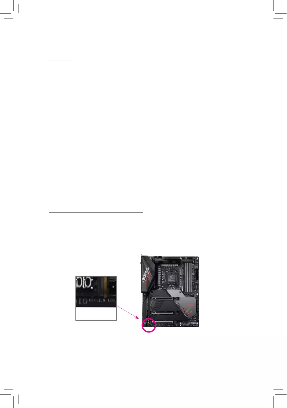
Identifying Your Motherboard Revision
The revision number on your motherboard looks like this: «REV: X.X.» For example, «REV:
1.0″ means the revision of the motherboard is 1.0. Check your motherboard revision before
updating motherboard BIOS, drivers, or when looking for technical information.
Example:

— 3 —
Table of Contents
Box Contents …………………………………………………………………………………………………….5
Optional Items …………………………………………………………………………………………………..5
Z590 VISION D Motherboard Layout ……………………………………………………………………6
Z590 VISION D Motherboard Block Diagram ………………………………………………………..7
Chapter 1 Hardware Installation ………………………………………………………………………….9
1-1 Installation Precautions ……………………………………………………………………….. 9
1-2 ProductSpecications ……………………………………………………………………….. 10
1-3 Installing the CPU and CPU Cooler……………………………………………………… 14
1-3-1 Installing the CPU ……………………………………………………………………………………..14
1-3-2 Installing the CPU Cooler …………………………………………………………………………..16
1-4 Installing the Memory ………………………………………………………………………… 17
1-4—1 DualChannelMemoryConguration …………………………………………………………..17
1-4-2 Installing a Memory ……………………………………………………………………………………18
1-5 Installing an Expansion Card ………………………………………………………………. 19
1-6 Setting up an AMD CrossFire™Conguration ……………………………………….. 20
1-7 Back Panel Connectors ……………………………………………………………………… 21
1-8 Internal Connectors …………………………………………………………………………… 24
Chapter 2 BIOS Setup ……………………………………………………………………………………..39
2-1 Startup Screen ………………………………………………………………………………….. 40
2-2 The Main Menu …………………………………………………………………………………. 41
2-3 Smart Fan 6 ……………………………………………………………………………………… 43
2-4 Favorites (F11) ………………………………………………………………………………….. 45
2-5 Tweaker ……………………………………………………………………………………………. 46
2-6 Settings ……………………………………………………………………………………………. 53
2-7 System Info. ……………………………………………………………………………………… 60
2-8 Boot …………………………………………………………………………………………………. 61
2-9 Save & Exit ………………………………………………………………………………………. 64
Chapter3 ConguringaRAIDSet …………………………………………………………………….65
3—1 ConguringSATAControllers ……………………………………………………………… 65
3-2 InstallingtheRAIDDriverandOperatingSystem ………………………………….. 70
3-3 Installing Intel® Optane™ Memory and Storage Management ………………….. 71

— 4 —
Chapter 4 Drivers Installation ……………………………………………………………………………75
4—1 Drivers & Software …………………………………………………………………………….. 75
4-2 Application Software ………………………………………………………………………….. 76
4-3 Information ……………………………………………………………………………………….. 76
Chapter 5 Unique Features……………………………………………………………………………….77
5—1 BIOS Update Utilities …………………………………………………………………………. 77
5—1-1 Updating the BIOS with the Q-Flash Utility …………………………………………………..77
5—1-2 Updating the BIOS with the @BIOS Utility ………………………………………………….. 80
5—1-3 Using Q-Flash Plus ……………………………………………………………………………………81
5-2 APP Center ………………………………………………………………………………………. 82
5—2-1 EasyTune ………………………………………………………………………………………………… 83
5-2-2 Fast Boot ………………………………………………………………………………………………… 84
5-2-3 Game Boost ……………………………………………………………………………………………. 85
5-2-4 RGBFusion …………………………………………………………………………………………….. 86
5-2-5 Smart Backup …………………………………………………………………………………………. 88
5-2—6 System Information Viewer ……………………………………………………………………….. 90
Chapter 6 Appendix …………………………………………………………………………………………91
6—1 ConguringAudioInputandOutput …………………………………………………….. 91
6—1-1 Conguring2/4/5.1/7.1-ChannelAudio …………………………………………………………91
6—1-2 ConguringS/PDIFOut ……………………………………………………………………………..93
6—1-3 Stereo Mix ………………………………………………………………………………………………. 94
6—1-4 UsingtheVoiceRecorder …………………………………………………………………………. 95
6-1—5 DTS:X® Ultra ……………………………………………………………………………………………. 96
6—2 Troubleshooting ………………………………………………………………………………… 98
6-2-1 Frequently Asked Questions …………………………………………………………………….. 98
6—2-2 Troubleshooting Procedure ………………………………………………………………………. 99
6-3 Debug LED Codes …………………………………………………………………………… 101
RegulatoryNotices ……………………………………………………………………………………. 105
Contact Us …………………………………………………………………………………………………111

— 5 —
Box Contents
5Z590 VISION D motherboard
5Motherboard driver disc
5User’s Manual
5Quick Installation Guide
5Four SATA cables
5One antenna
5M.2 screw(s)
5OneRGBLEDstripextensioncable
5One noise detection cable
5Two thermistor cables
5One G Connector
Optional Items
2-portUSB2.0bracket(PartNo.12CR1-1UB030-6*R)
eSATAbracket(PartNo.12CF1-3SATPW-4*R)
3.5″FrontPanelwith2USB3.2Gen1ports(PartNo.12CR1-FPX582-2*R)
The box contents above are for reference only and the actual items shall depend on the product package you
obtain. The box contents are subject to change without notice.
— 6 —
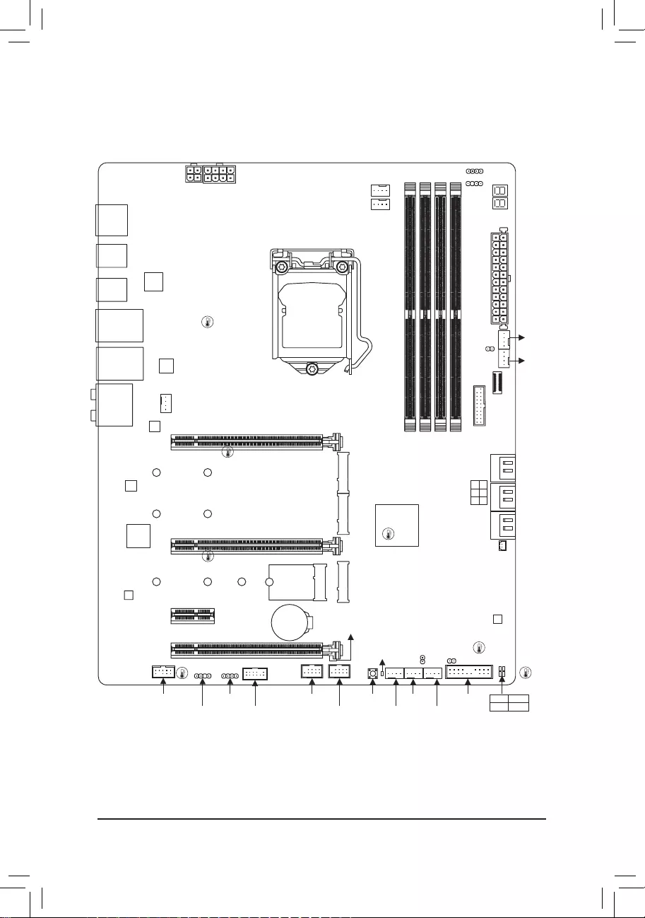
Z590 VISION D Motherboard Layout
(Note) For debug code information, please refer to Chapter 6.
TYPEC_1
U32G2_2
TYPEC_2
U32G2_1
LGA1200
ATX
AUDIO
DDR4_A1
DDR4_A2
DDR4_B1
DDR4_B2
BAT
Intel® Z590
CLR_CMOS
M_BIOS
Intel®
2.5GbE
LAN
Intel® 2.5GbE LAN
CODEC
PCIEX16
PCIEX8
PCIEX4
PCIEX1
F_U320G
F_U32
SYS_FAN5_PUMP SYS_FAN2
DB_PORT (Note)
EC_TEMP2
EC_TEMP1
SYS_FAN1
80110
M2A_CPU
80110
M2M_SB
6080110
M2P_SB
CNVI
Z590 VISION D
QFLASH_
PLUS
QFLED
F_USB2 F_PANELF_AUDIO LED_C1
F_USB1
NOISE_
SENSOR
SPI_TPMD_LED1 SYS_FAN6_
PUMP
SYS_FAN3
CPU_FAN
CPU_OPT
SYS_FAN4
iTE®
SuperI/O
D_LED2
LED_C2
ATX_12V_2X4ATX_12V_2X2
USB 2.0 Hub
Intel®
Thunderbolt™ 4
Controller
USB 3.2
Gen 1 Hub
SATA3 531
420
CPU DRAM
VGA BOOT
DP_HDMIU32_LAN2U32_LAN1
Temperature
sensor
— 7 —
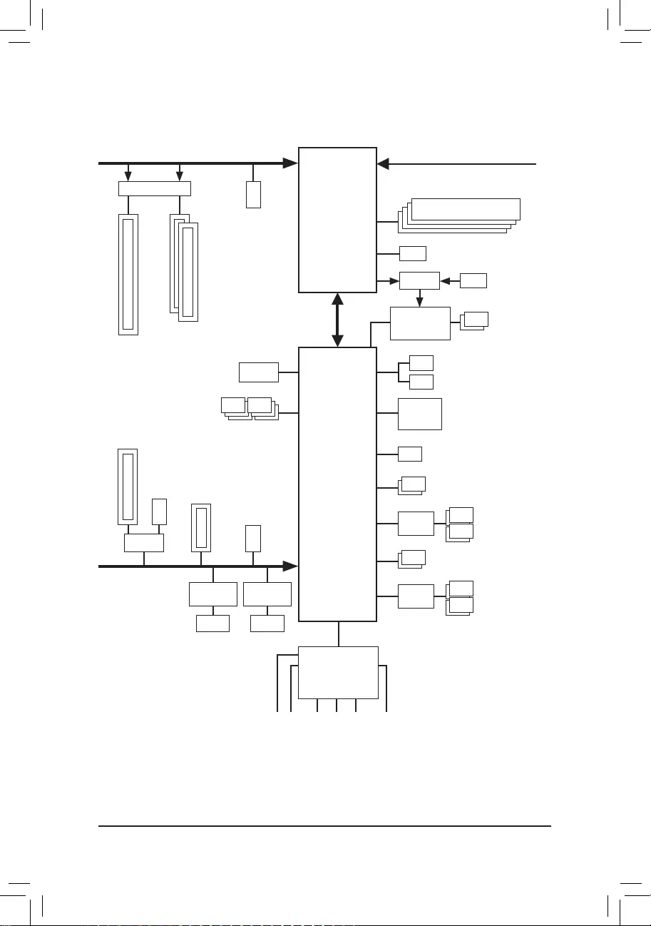
Z590 VISION D Motherboard Block Diagram
LGA1200 CPU
DMI 3.0
eSPI
Bus
SPI
Bus
PCI Express 3.0 Bus
Center/Subwoofer
Speaker Out
Line Out
MIC
Line In
S/PDIFOut
RearSpeakerOut
CODEC
iTE®
SuperI/O
4 USB 3.2 Gen 1
4USB2.0/1.1
2 USB 3.2 Gen 2 Type A
2 USB 3.2 Gen 1
Intel® Z590
x4
LAN
RJ45
Intel®
2.5GbE LAN
x1
LAN
RJ45
Intel®
2.5GbE LAN
x1
1 PCI Express x1
M.2 Socket 3
(M2M_SB) USB 3.2
Gen 1 Hub
USB 2.0
Hub
BIOS
TPM
PCI Express 4.0 (Note)/3.0Bus
1 PCI Express x16
2 PCI Express x8
Switch
x16x16
or
(Note) Actual support may vary by CPU.
M.2 WIFI
6SATA6Gb/s
(SATA3 0~6)
x4
Switch
1 PCI Express x4
M.2 Socket 3
(M2P_SB)
or
CPUCLK+/-(100~500MHz)
DDR43200 (Note)/3000 (Note)/2933 (Note)/
2666/2400/2133MHz
1 USB Type-C®,
with USB 3.2 Gen 2×2 support
M.2 Socket 3
(M2A_CPU) (Note)
DDI
x4
DDI
2 USB Type-C®, with
USB 3.2 Gen 2 support
(or 2 Intel® Thunderbolt™ 4)
HDMI 1.4
DisplayPort In
PCIe 3.0 Bus
Switch
Intel®
Thunderbolt™ 4
Controller

— 8 —

— 9 —
1-1 Installation Precautions
The motherboard contains numerous delicate electronic circuits and components which can become
damaged as a result of electrostatic discharge (ESD). Prior to installation, carefully read the user’s
manual and follow these procedures:
•Prior to installation, make sure the chassis is suitable for the motherboard.
•Priorto installation, do notremove orbreak motherboard S/N(Serial Number)sticker or
warranty sticker provided by your dealer. These stickers are required for warranty validation.
•Always remove the AC power by unplugging the power cord from the power outlet before
installing or removing the motherboard or other hardware components.
•When connecting hardware components to the internal connectors on the motherboard, make
sure they are connected tightly and securely.
•When handling the motherboard, avoid touching any metal leads or connectors.
•It is best to wear an electrostatic discharge (ESD) wrist strap when handling electronic
components such as a motherboard, CPU or memory. If you do not have an ESD wrist strap,
keepyourhandsdryandrsttouchametalobjecttoeliminatestaticelectricity.
•Prior to installing the motherboard, please have it on top of an antistatic pad or within an
electrostatic shielding container.
•Before connecting or unplugging the power supply cable from the motherboard, make sure
the power supply has been turned off.
•Before turning on the power, make sure the power supply voltage has been set according to
the local voltage standard.
•Before using the product, please verify that all cables and power connectors of your hardware
components are connected.
•To prevent damage to the motherboard, do not allow screws to come in contact with the
motherboard circuit or its components.
•Make sure there are no leftover screws or metal components placed on the motherboard or
within the computer casing.
•Do not place the computer system on an uneven surface.
•Do not place the computer system in a high-temperature or wet environment.
•Turning on the computer power during the installation process can lead to damage to system
components as well as physical harm to the user.
•If you are uncertain about any installation steps or have a problem related to the use of the
product,pleaseconsultacertiedcomputertechnician.
•If you use an adapter, extension power cable, or power strip, ensure to consult with its installation
and/orgroundinginstructions.
Chapter 1 Hardware Installation

— 10 —
1-2 ProductSpecications
CPU LGA1200 package:
— 11th Generation Intel® Core™ i9 processors/Intel® Core™ i7 processors/
Intel® Core™ i5 processors
— 10th Generation Intel® Core™ i9 processors/Intel® Core™ i7 processors/Intel®
Core™ i5 processors/Intel® Core™ i3 processors/Intel® Pentium® processors/
Intel® Celeron® processors*
* Limited to processors with 4 MB Intel® Smart Cache, Intel® Celeron® G5xx5 family.
(Go to GIGABYTE’s website for the latest CPU support list.)
L3 cache varies with CPU
Chipset Intel® Z590 Express Chipset
Memory 11th Generation Intel® Core™ i9/i7/i5 processors:
— Support for DDR4 3200/3000/2933/2666/2400/2133 MHz memory modules
10th Generation Intel® Core™ i9/i7 processors:
— Support for DDR4 2933/2666/2400/2133 MHz memory modules
10th Generation Intel® Core™ i5/i3/Pentium®/Celeron® processors:
— Support for DDR4 2666/2400/2133 MHz memory modules
4 x DDR4 DIMM sockets supporting up to 128 GB (32 GB single DIMM capacity)
of system memory
Dual channel memory architecture
Support for ECC Un-buffered DIMM 1Rx8/2Rx8 memory modules (operate in
non-ECC mode)
Support for non-ECC Un-buffered DIMM 1Rx8/2Rx8/1Rx16 memory modules
Support for Extreme Memory Prole (XMP) memory modules
(Go to GIGABYTE’s website for the latest supported memory speeds and memory
modules.)
Onboard
Graphics
Integrated Graphics Processor+Intel® Thunderbolt™ 4 Controller:
— 1 x VisionLINK TB connector (Intel® Thunderbolt™ 4/USB Type-C® port)
— 1 x Intel® Thunderbolt™ 4 connector (USB Type-C® port)
* The Intel® Thunderbolt™ 4 connectors support DisplayPort and Thunderbolt™ video
outputs and a maximum resolution of 5120×2880@60 Hz with 24 bpp (via single
display output)
* Because of the limited I/O resources of the PC architecture, the number of Thunderbolt™
devices that can be used is dependent on the number of the PCI Express devices
being installed. (Refer to Chapter 1-7, «Back Panel Connectors,» for more information.)
* Support for DisplayPort 1.4 version and HDCP 2.3.
Integrated Graphics Processor-Intel® HD Graphics support:
— 1 x HDMI port, supporting a maximum resolution of 4096×2160@30 Hz
* Support for HDMI 1.4 version and HDCP 2.3.
(Graphics specications may vary depending on CPU support.)
Audio Realtek® ALC4080 codec
Support for DTS:X® Ultra
High Denition Audio
2/4/5.1/7.1-channel
Support for S/PDIF Out
LAN 2 x Intel® 2.5GbE LAN chips (2.5 Gbit/1 Gbit/100 Mbit)

— 11 —
Wireless
Communication
Module
Intel® Wi-Fi 6 AX200
- WIFIa,b,g,n,ac,ax,supporting2.4/5GHzDual-Band
— BLUETOOTH 5.1
- Supportfor11ax160MHzwirelessstandardandupto2.4Gbpsdatarate
* Actualdataratemayvarydependingonenvironmentandequipment.
Expansion Slots 1 x PCI Express x16 slot, running at x16 (PCIEX16)
* Foroptimumperformance,ifonlyonePCIExpressgraphicscardistobeinstalled,
be sure to install it in the PCIEX16 slot.
1 x PCI Express x16 slot, running at x8 (PCIEX8)
* ThePCIEX8slotsharesbandwidthwiththePCIEX16slot.WhenthePCIEX8slotis
populated, the PCIEX16 slot operates at up to x8 mode.
(The PCIEX16 and PCIEX8 slots conform to PCI Express 4.0 standard.) (Note)
1 x PCI Express x16 slot, running at x4 (PCIEX4)
* ThePCIEX4slotsharesbandwidthwiththeM2P_SBconnector.ThePCIEX4slot
operates at up to x2 mode when a PCIe SSD is installed in the M2P_SB connector.
1 x PCI Express x1 slot
(The PCIEX4 and PCI Express x1 slots conform to PCI Express 3.0 standard.)
Multi-Graphics
Technology Support for AMD Quad-GPU CrossFire™ and 2-Way AMD CrossFire™ technologies
Storage Interface CPU:
- 1xM.2connector(Socket3,Mkey,type2280/22110PCIe4.0x4/x2SSD
support) (M2A_CPU) (Note)
Chipset:
- 1xM.2connector(Socket3,Mkey,type2280/22110SATAandPCIe3.0
x4/x2SSDsupport)(M2M_SB)
- 1xM.2connector(Socket3,Mkey,type2260/2280/22110PCIe3.0x4/x2
SSD support) (M2P_SB)
- 6xSATA6Gb/sconnectors
SupportforRAID0,RAID1,RAID5,andRAID10
* Referto«1-8InternalConnectors,»fortheinstallationnoticesforthePCIEX4,M.2,
and SATA connectors.
Intel® Optane™MemoryReady
USB Chipset+Intel® Thunderbolt™ 4 Controller:
— 2 x USB Type-C® ports on the back panel, with USB 3.2 Gen 2 support
Chipset:
— 1 x USB Type-C® port with USB 3.2 Gen 2×2 support, available through the
internal USB header
— 2 x USB 3.2 Gen 2 Type-A ports (red) on the back panel
— 2 x USB 3.2 Gen 1 ports available through the internal USB header
Chipset+USB 3.2 Gen 1 Hub:
— 4 x USB 3.2 Gen 1 ports on the back panel
Chipset+USB 2.0 Hub:
- 4xUSB2.0/1.1portsavailablethroughtheinternalUSBheaders
(Note) Supported by 11th Generation processors only.
— 12 —
Internal
Connectors
1 x 24-pin ATX main power connector
1 x 8-pin ATX 12V power connector
1 x 4-pin ATX 12V power connector
1 x CPU fan header
1 x water cooling CPU fan header
4 x system fan headers
2xsystemfan/watercoolingpumpheaders
2 x addressable LED strip headers
2xRGBLEDstripheaders
3 x M.2 Socket 3 connectors
6xSATA6Gb/sconnectors
1 x front panel header
1 x front panel audio header
1 x USB Type-C® header, with USB 3.2 Gen 2×2 support
1 x USB 3.2 Gen 1 header
2xUSB2.0/1.1headers
1 x noise detection header
1xTrustedPlatformModuleheader(FortheGC-TPM2.0SPI/GC-TPM2.0SPI
2.0 module only)
2 x temperature sensor headers
1 x Clear CMOS jumper
1 x Q-Flash Plus button
Back Panel
Connectors
1 x DisplayPort In port
1 x HDMI port
2xSMAantennaconnectors(2T2R)
2 x Thunderbolt™ 4 connectors (USB Type-C® port, with USB 3.2 Gen 2 support)
2 x USB 3.2 Gen 2 Type-A ports (red)
4 x USB 3.2 Gen 1 ports
2xRJ-45ports
1xopticalS/PDIFOutconnector
5 x audio jacks
I/OController iTE®I/OControllerChip
Hardware
Monitor
Voltage detection
Temperature detection
Fan speed detection
Watercoolingowratedetection
Fan fail warning
Fan speed control
* Whetherthefan(pump)speedcontrolfunctionissupportedwilldependonthefan
(pump) you install.
Noise detection
BIOS 1x256Mbitash
Use of licensed AMI UEFI BIOS
PnP 1.0a, DMI 2.7, WfM 2.0, SM BIOS 2.7, ACPI 5.0
— 13 —
Please visit GIGABYTE’s website
for support lists of CPU, memory
modules, SSDs, and M.2 devices.
Please visit the SupportUtility List
page on GIGABYTE’s website to
download the latest version of apps.
Unique Features Support for APP Center
* AvailableapplicationsinAPPCentermayvarybymotherboardmodel.Supported
functionsofeachapplicationmayalsovarydependingonmotherboardspecications.
— @BIOS
— EasyTune
— Fast Boot
— Game Boost
- ON/OFFCharge
- RGBFusion
— Smart Backup
— System Information Viewer
Support for Q-Flash Plus
Support for Q-Flash
Support for Xpress Install
Bundled
Software
Norton® Internet Security (OEM version)
cFosSpeed
Operating
System Support for Windows 10 64-bit
Form Factor ATX Form Factor; 30.5cm x 24.4cm
* GIGABYTEreservestherighttomakeanychangestotheproductspecicationsandproduct-relatedinformationwithout
prior notice.
— 14 —
1-3 Installing the CPU and CPU Cooler
ReadthefollowingguidelinesbeforeyoubegintoinstalltheCPU:
•Make sure that the motherboard supports the CPU.
(Go to GIGABYTE’s website for the latest CPU support list.)
•Always turn off the computer and unplug the power cord from the power outlet before installing the
CPU to prevent hardware damage.
•Locate the pin one of the CPU. The CPU cannot be inserted if oriented incorrectly. (Or you may
locate the notches on both sides of the CPU and alignment keys on the CPU socket.)
•Apply an even and thin layer of thermal grease on the surface of the CPU.
•Do not turn on the computer if the CPU cooler is not installed, otherwise overheating and damage
of the CPU may occur.
•SettheCPUhostfrequencyinaccordancewiththeCPUspecications.Itisnotrecommended
thatthesystembusfrequencybesetbeyondhardwarespecicationssinceitdoesnotmeetthe
standard requirements for the peripherals. If you wish to set the frequency beyond the standard
specications,pleasedosoaccordingtoyourhardwarespecicationsincludingtheCPU,graphics
card, memory, hard drive, etc.
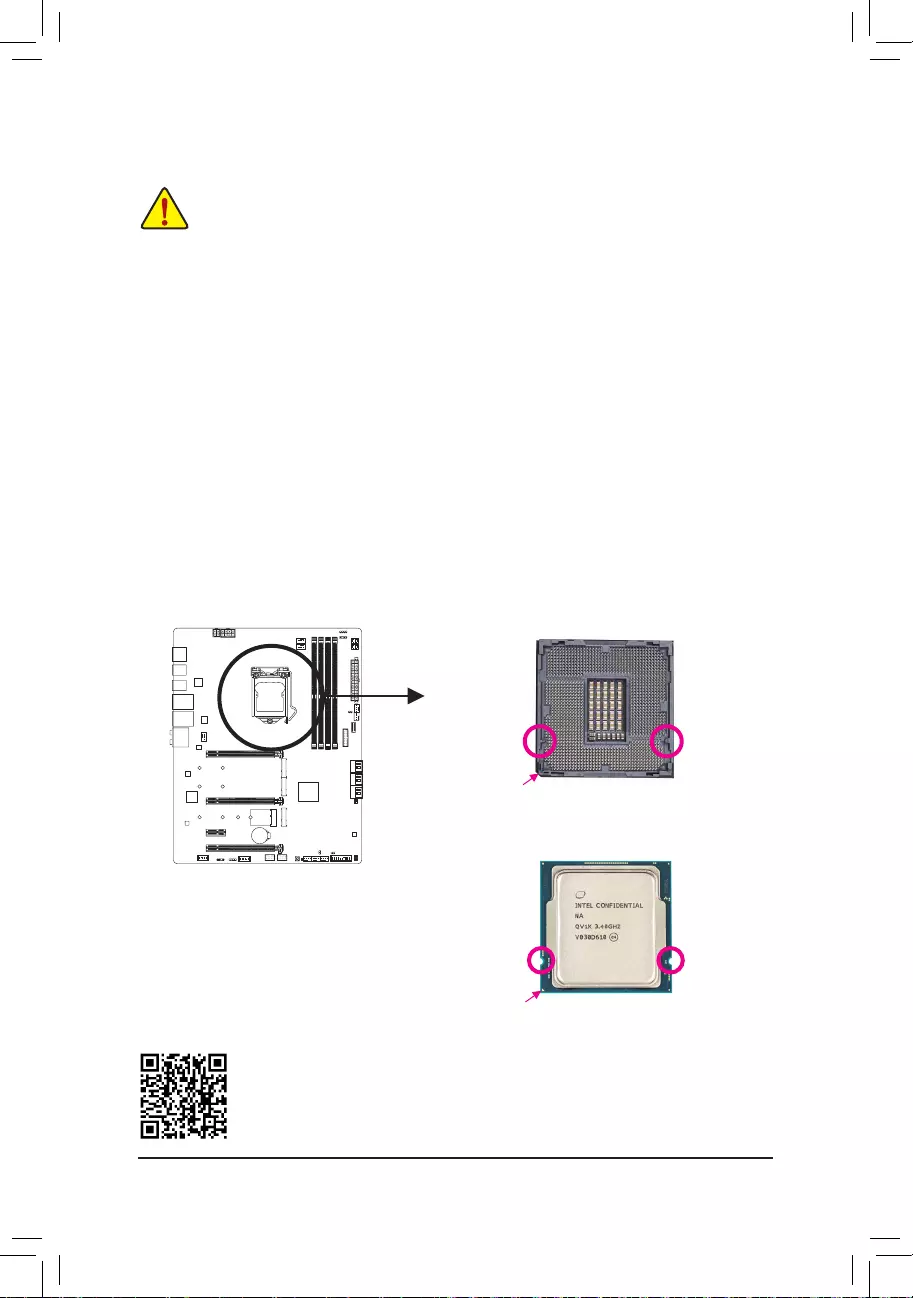
1-3—1 Installing the CPU
A. Locate the alignment keys on the motherboard CPU socket and the notches on the CPU.
Please visit GIGABYTE’s website for details on hardware installation.
Triangle Pin One Marking on the CPU
NotchNotch
LGA1200 CPU
Alignment KeyAlignment Key
LGA1200 CPU Socket
Pin One Corner of the CPU Socket
— 15 —
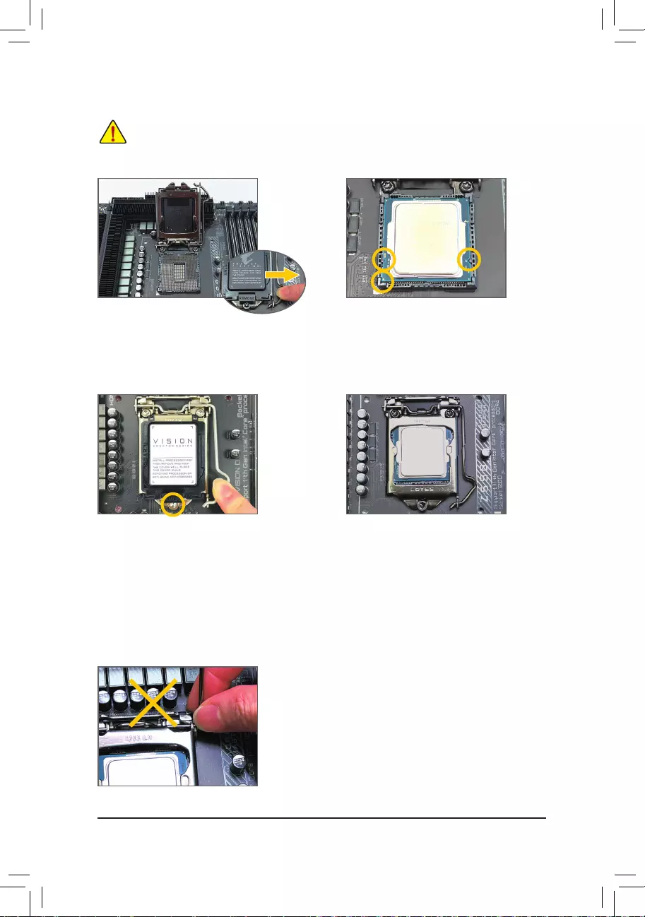
B. Follow the steps below to correctly install the CPU into the motherboard CPU socket.
•Before installing the CPU, make sure to turn off the computer and unplug the power cord from
the power outlet to prevent damage to the CPU.
•To protect the socket contacts, do not remove the protective plastic cover unless the CPU is
inserted into the CPU socket. Save the cover properly and replace it if the CPU is removed.
Step 1:
Gently press the CPU socket lever handle down
andawayfromthesocketwithyournger.Then
completely lift the CPU socket lever and the metal
loadplate/plasticcoverwillbeliftedaswell.
Step 2:
HoldtheCPUwithyourthumbandindexngers.
Align the CPU pin one marking (triangle) with the
pin one corner of the CPU socket (or you may align
the CPU notches with the socket alignment keys)
and gently insert the CPU into position.
Step 4:
Finally, secure the lever under its retention tab to
complete the installation of the CPU.
NOTE:
Hold the CPU socket lever by the handle, not the lever base portion.
Step 3:
Once the CPU is properly inserted, carefully
replace the load plate. When replacing the load
plate, make sure the front end of the load plate
is under the shoulder screw. Then press the CPU
socket lever. The protective plastic cover may
pop off from the load plate during the process of
engagingthelever.Removethecover.(Savethe
cover properly and always replace it when the
CPU is not installed.)
— 16 —
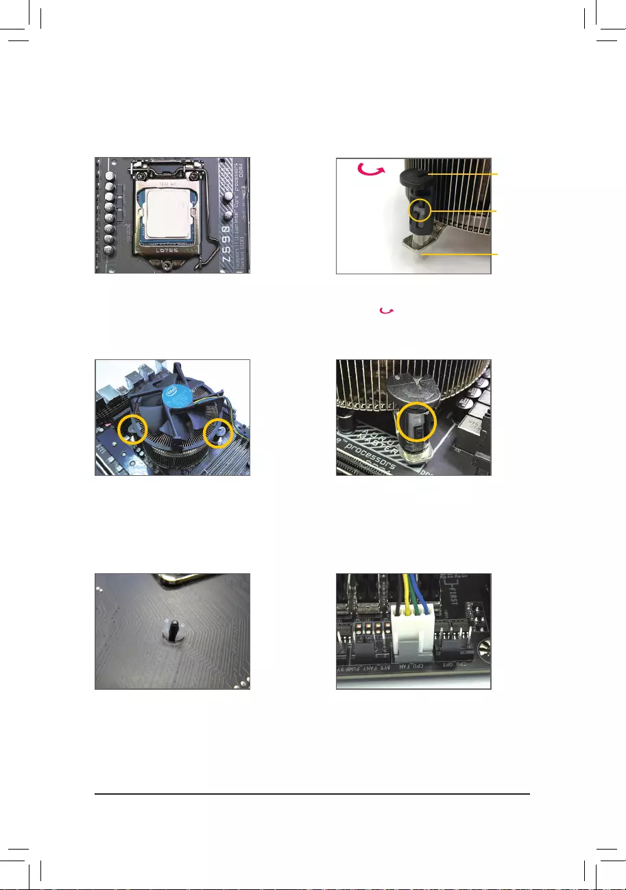
1-3-2 Installing the CPU Cooler
RefertothestepsbelowtocorrectlyinstalltheCPUcooleronthemotherboard.(Actualinstallationprocessmay
differdependingtheCPUcoolertobeused.Refertotheuser’smanualforyourCPUcooler.)
Step 5:
After the installation, check the back of the
motherboard. If the push pin is inserted as the
picture above shows, the installation is complete.
Step 6:
Finally, attach the power connector of the CPU
cooler to the CPU fan header (CPU_FAN) on the
motherboard.
Step 1:
Apply an even and thin layer of thermal grease on
the surface of the installed CPU.
Step 2:
Before installing the cooler, note the direction of the
arrow sign on the male push pin. (Turning the
push pin along the direction of arrow is to remove
the cooler, on the contrary, is to install.)
Step 3:
Place the cooler atop the CPU, aligning the
four push pins through the pin holes on the
motherboard. Push down on the push pins
diagonally.
Step 4:
You should hear a «click» when pushing down each
push pin. Check that the Male and Female push
pins are joined closely.
(RefertoyourCPUcoolerinstallationmanualfor
instructions on installing the cooler.)
Male
Push Pin
Female
Push Pin
The Top
of Female
Push Pin
Direction of
the Arrow Sign
on the Male
Push Pin
— 17 —
Due to CPU limitations, read the following guidelines before installing the memory in Dual Channel mode.
1. Dual Channel mode cannot be enabled if only one memory module is installed.
2. When enabling Dual Channel mode with two or four memory modules, it is recommended that memory
of the same capacity, brand, speed, and chips be used.
DDR4_A1
DDR4_A2
DDR4_B1
DDR4_B2
1-4 Installing the Memory
Readthefollowingguidelinesbeforeyoubegintoinstallthememory:
•Make sure that the motherboard supports the memory. It is recommended that memory of the same
capacity, brand, speed, and chips be used.
(Go to GIGABYTE’s website for the latest supported memory speeds and memory modules.)
•Always turn off the computer and unplug the power cord from the power outlet before installing the
memory to prevent hardware damage.
•Memory modules have a foolproof design. A memory module can be installed in only one direction.
If you are unable to insert the memory, switch the direction.
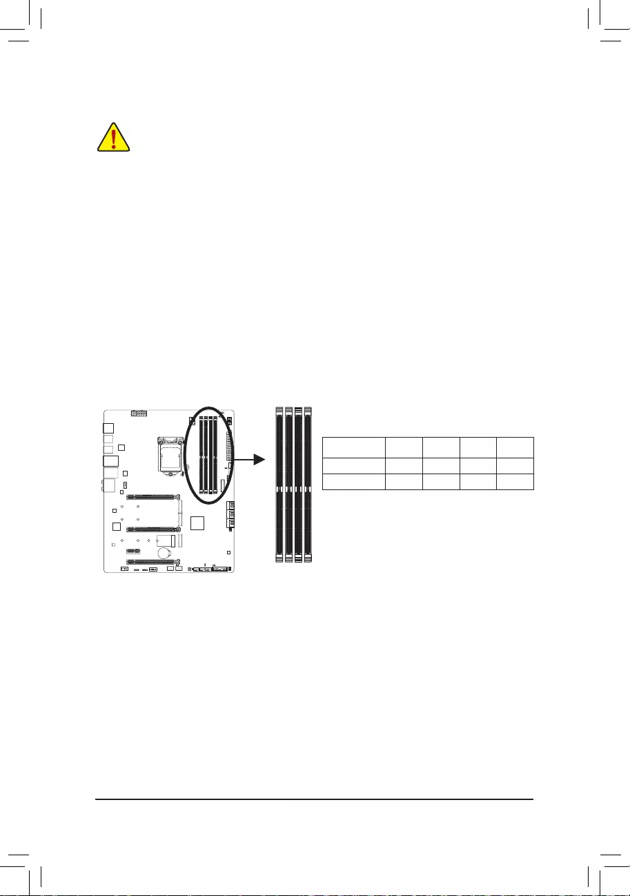
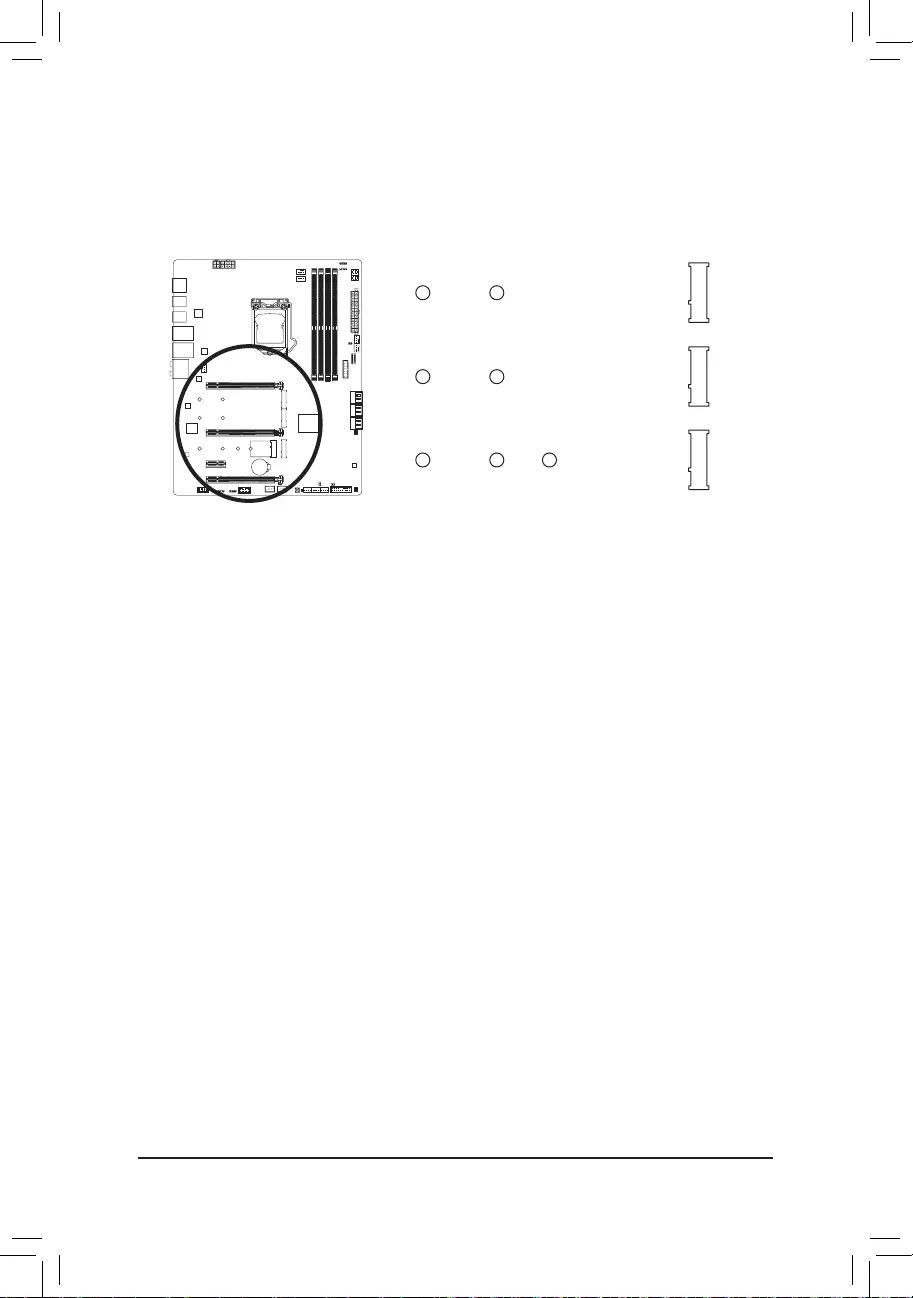
1-4-1 DualChannelMemoryConguration
This motherboard provides four memory sockets and supports Dual Channel Technology. After the memory
isinstalled,theBIOSwillautomaticallydetectthespecicationsandcapacityofthememory.EnablingDual
Channel memory mode will double the original memory bandwidth.
The four memory sockets are divided into two channels and each channel has two memory sockets as following:
ChannelA:DDR4_A1,DDR4_A2
ChannelB:DDR4_B1,DDR4_B2
RecommandedDualChannelMemoryConguration:
(SS=Single-Sided, DS=Double-Sided, «- -«=No Memory)
DDR4_A1 DDR4_A2 DDR4_B1 DDR4_B2
2 Modules — — DS/SS — — DS/SS
4 Modules DS/SS DS/SS DS/SS DS/SS
— 18 —
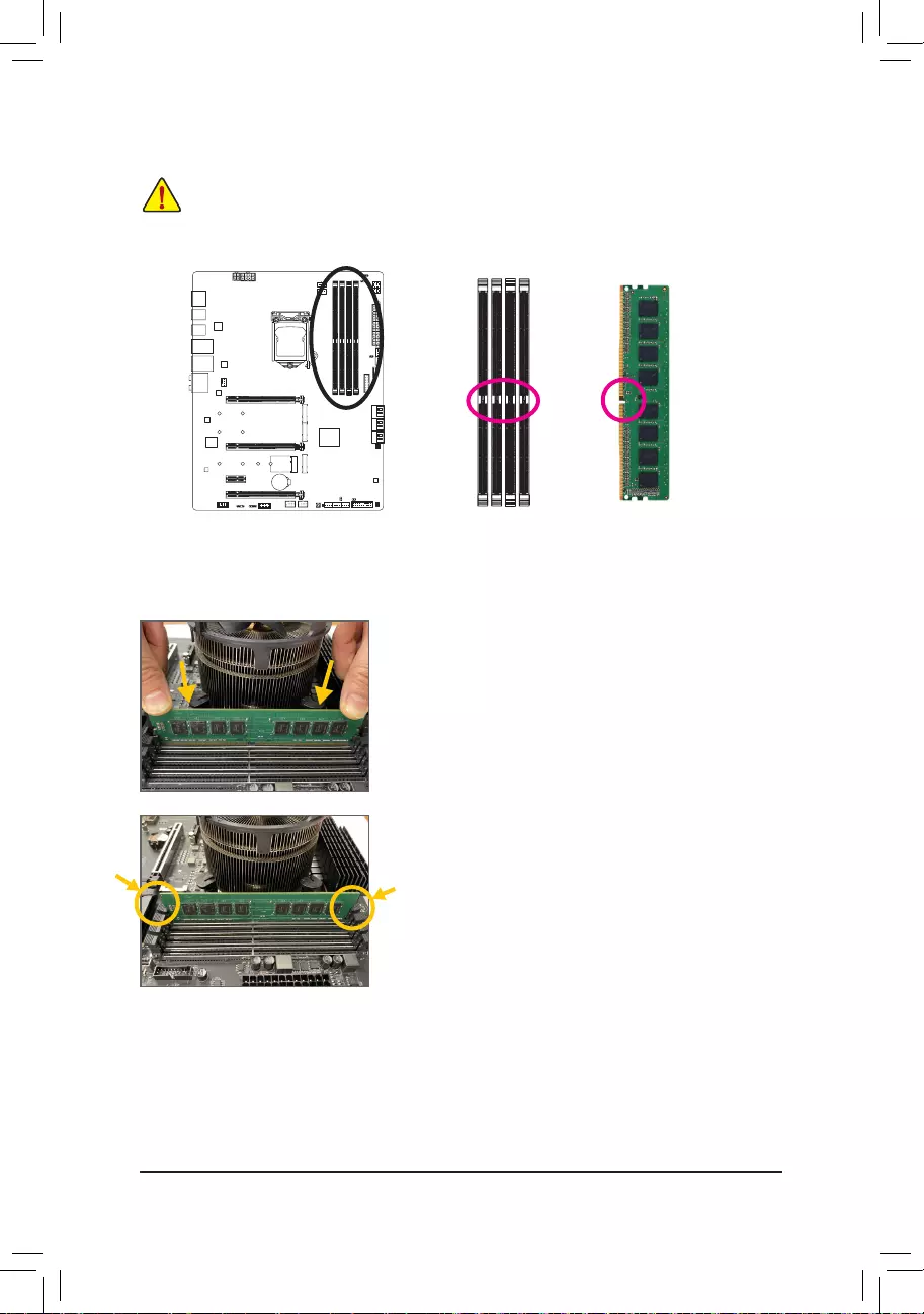
Notch
DDR4DIMM
ADDR4memorymodulehasanotch,soitcanonlytinonedirection.Followthestepsbelowtocorrectlyinstall
your memory modules in the memory sockets.
Step 1:
Note the orientation of the memory module. Spread the retaining clips
at both ends of the memory socket. Place the memory module on the
socket.Asindicatedinthepictureontheleft,placeyourngerson
the top edge of the memory, push down on the memory and insert it
vertically into the memory socket.
Step 2:
The clips at both ends of the socket will snap into place when the
memory module is securely inserted.
Before installing a memory module, make sure to turn off the computer and unplug the power cord
from the power outlet to prevent damage to the memory module. DDR4 and DDR3 DIMMs are not
compatible to each other or DDR2 DIMMs. Be sure to install DDR4 DIMMs on this motherboard.
1-4-2 Installing a Memory
— 19 —
1-5 Installing an Expansion Card
Readthefollowingguidelinesbeforeyoubegintoinstallanexpansioncard:
•Make sure the motherboard supports the expansion card. Carefully read the manual that came
with your expansion card.
•Always turn off the computer and unplug the power cord from the power outlet before installing an
expansion card to prevent hardware damage.
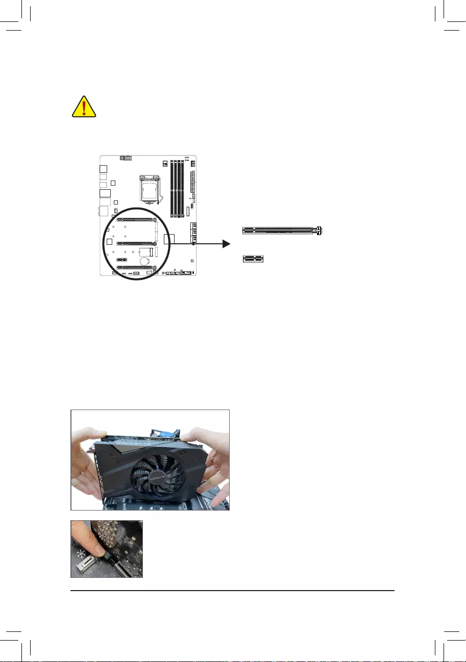
PCI Express x16 Slot
PCI Express x1 Slot
Follow the steps below to correctly install your expansion card in the expansion slot.
1. Locateanexpansionslotthatsupportsyourcard.Removethemetalslotcoverfromthechassisbackpanel.
2. Align the card with the slot, and press down on the card until it is fully seated in the slot.
3. Make sure the metal contacts on the card are completely inserted into the slot.
4. Secure the card’s metal bracket to the chassis back panel with a screw.
5. After installing all expansion cards, replace the chassis cover(s).
6. Turn on your computer. If necessary, go to BIOS Setup to make any required BIOS changes for your
expansion card(s).
7. Install the driver provided with the expansion card in your operating system.
Example:InstallingandRemovingaPCIExpressGraphicsCard:
•Installing a Graphics Card:
Gently push down on the top edge of the card until
it is fully inserted into the PCI Express slot. Make
sure the card is securely seated in the slot and
does not rock.
•RemovingtheCard:
Gently push back on the lever on the slot and then lift the card straight out from
the slot.
— 20 —
B.ConnectingtheGraphicsCards
Step 1:
Observe the steps in «1-5 Installing an Expansion Card» and install the graphics cards on the PCIEX16 and
PCIEX8 slots.
Step 2:
Insert the CrossFire (Note) bridge connector in the CrossFire gold edge connectors on top of the cards.
Step 3:
Plug the display cable into the graphics card on the PCIEX16 slot.
Procedure and driver screen for enabling CrossFire technology may differ by graphics cards and
driver version. Refer to the manual that came with your graphics cards for more information about
enabling CrossFire technology.
1-6 SettingupanAMDCrossFire™Conguration
(Note) The bridge connector(s) may be needed or not depending on your graphics cards.
A.SystemRequirements
—Windows 10 64-bit operating system
—A CrossFire-supported motherboard with two PCI Express x16 slots and correct driver
—CrossFire-ready graphics cards of identical brand and chip and correct driver
—CrossFire (Note) bridge connector
—A power supply with sufcient power is recommended (Refer to the manual of your graphics cards for the
power requirement)
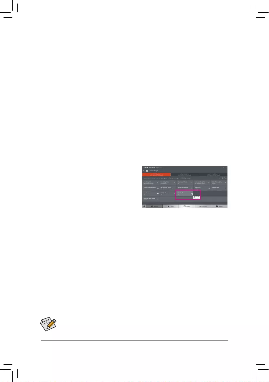
C.ConguringtheGraphicsCardDriver
After installing the graphics card driver in the operating
system, go to the AMDRADEON SETTINGS screen.
Browse to GamingGlobalSettings and ensure AMD
CrossFire is set to On.
— 21 —
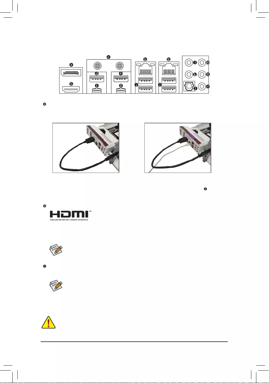
1-7 Back Panel Connectors
DisplayPort In Port
The DisplayPort In port offers video outputs to the motherboard. Refer to the pictures below and the
Thunderbolt™ 4 Connector introduction for more information.
HDMI Port
The HDMI port supports HDCP 2.3 and Dolby TrueHD and DTS HD Master
Audio formats. It also supports up to 192KHz/16bit 7.1-channel LPCM audio
output. You can use this port to connect your HDMI-supported monitor. The maximum supported
resolution is 4096×2160@30 Hz, but the actual resolutions supported are dependent on the monitor
being used.
SMA Antenna Connectors (2T2R)
Use this connector to connect an antenna.
Tighten the antennas to the antenna connectors and then aim the antennas correctly for better
signal reception.
After installing the HDMI device, make sure to set the default sound playback device to HDMI.
(The item name may differ depending on your operating system.)
•When removing the cable connected to a back panel connector, rst remove the cable from your
device and then remove it from the motherboard.
•When removing the cable, pull it straight out from the connector. Do not rock it side to side to
prevent an electrical short inside the cable connector.
Step 1:
Connect your DisplayPort cable or Mini-DisplayPort
cable (purchased separately) from the graphics
card to the DisplayPort In port on the back panel.
Step 2:
Then connect the DisplayPort or Thunderbolt™
devices to VisionLINK TB connector to complete.
— 22 —
USB 3.2 Gen 1 Port
The USB 3.2 Gen 1 port supports the USB 3.2 Gen 1 specication and is compatible to the USB 2.0
specication. Use this port for USB devices.
Connection/
Speed LED Activity LED
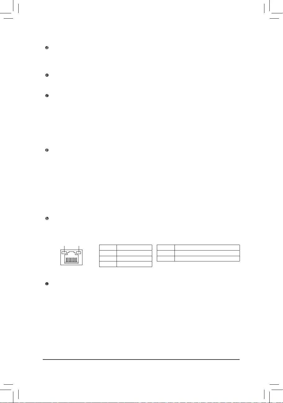
LAN Port
Connection/Speed LED:
State Description
Green 2.5 Gbps data rate
Orange 1 Gbps data rate
Off 100 Mbps data rate
Activity LED:
State Description
Blinking Data transmission or receiving is occurring
On No data transmission or receiving is occurring
USB 3.2 Gen 2 Type-A Port (Q-Flash Plus Port)
The USB 3.2 Gen 2 port supports the USB 3.2 Gen 2 specication and is compatible to the USB 3.2 Gen 1
and USB 2.0 specication. Use this port for USB devices. Before using Q-Flash Plus (Note), make sure to
insert the USB ash drive into this port rst.
USB 3.2 Gen 2 Type-A Port (Red)
The USB 3.2 Gen 2 port supports the USB 3.2 Gen 2 specication and is compatible to the USB 3.2 Gen 1
and USB 2.0 specication. Use this port for USB devices.
VisionLINK TB Connector (Thunderbolt™ 4/USB Type-C® Port)
The connector supports GIGABYTE’s VisionLINK technology. It is based on the Thunderbolt™ 4 specication
and has display and data transmission capabilities with 20V@3A (60W) of power delivery. You can connect
a drawing tablet or a standard DisplayPort/Thunderbolt™ monitor to this connector with an adapter. The
VisionLINK TB connector supports a resolution of up to 4K@60 Hz when a graphics card is connected to the
DisplayPort In port for the VisionLINK TB connector to output (the actual resolutions supported are dependent
on the monitor being used.) Also, the connector is reversible and supports the USB 3.2 Gen 2 specication
and is compatible to the USB 3.2 Gen 1 and USB 2.0 specication. You can use this port for USB devices, too.
Thunderbolt™ 4 Connector (USB Type-C® Port)
The connector supports standard DisplayPort and Thunderbolt™ video outputs. You can connect a standard
DisplayPort/Thunderbolt™ monitor to this connector with an adapter. The Thunderbolt™ connector can
daisy chain up to ve Thunderbolt™ devices. Because of the limited I/O resources of the PC architecture,
the number of Thunderbolt™ devices that can be used is dependent on the number of the PCI Express
devices being installed. You can adjust the Thunderbolt™ settings under SettingsThunderbolt Conguration
in BIOS Setup. The maximum supported resolution is 5120 x 2880@60 Hz with 24 bpp via single display
output, but the actual resolutions supported are dependent on the monitor being used. Also, the connector
is reversible and supports the USB 3.2 Gen 2 specication and is compatible to the USB 3.2 Gen 1 and
USB 2.0 specication. You can use this port for USB devices, too.
RJ-45 LAN Port
The Gigabit Ethernet LAN port provides Internet connection at up to 2.5 Gbps data rate. The following
describes the states of the LAN port LEDs.
(Note) To enable Q-Flash Plus function, refer to Chapter 5, «Unique Features,» for more information.

— 23 —
Audio Jack Congurations:
Jack Headphone/
2-channel 4-channel 5.1-channel 7.1-channel
Center/Subwoofer Speaker Out a a
Rear Speaker Out aaa
Line In/Side Speaker Out a
Line Out/Front Speaker Out aaaa
Mic In a
•If you want to install a Side Speaker, you need to retask the Line in jack to be Side Speaker
out through the audio driver.
•To enable or congure the audio amplifying function for the Line out jack, please access the
Realtek Audio Console application.
Center/Subwoofer Speaker Out
Use this audio jack to connect center/subwoofer speakers.
Rear Speaker Out
Use this audio jack to connect rear speakers.
Optical S/PDIF Out Connector
This connector provides digital audio out to an external audio system that supports digital optical audio.
Before using this feature, ensure that your audio system provides an optical digital audio in connector.
Line In/Side Speaker Out
The line in jack. Use this audio jack for line in devices such as an optical drive, walkman, etc.
Line Out/Front Speaker Out
The line out jack. This jack supports audio amplifying function. For better sound quality, it is recommended
that you connect your headphone/speaker to this jack (actual effects may vary by the device being used).
Mic In
The Mic in jack.
— 24 —
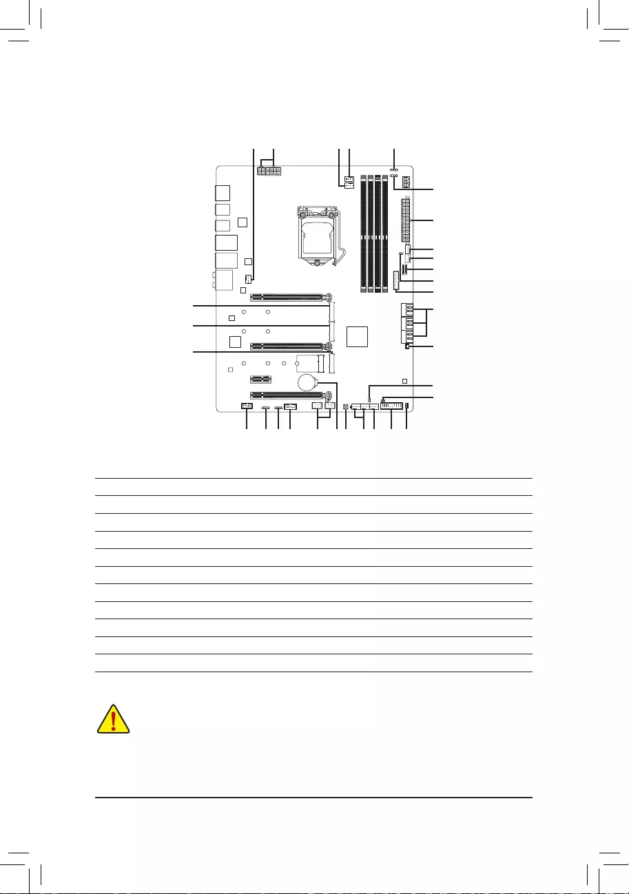
1-8 Internal Connectors
Readthefollowingguidelinesbeforeconnectingexternaldevices:
•First make sure your devices are compliant with the connectors you wish to connect.
•Before installing the devices, be sure to turn off the devices and your computer. Unplug the power
cord from the power outlet to prevent damage to the devices.
•After installing the device and before turning on the computer, make sure the device cable has
been securely attached to the connector on the motherboard.
1) ATX_12V_2X2/ATX_12V_2X4
2) ATX
3) CPU_FAN
4) SYS_FAN1/2/3/4
5) SYS_FAN5/6_PUMP
6) CPU_OPT
7) EC_TEMP1/EC_TEMP2
 D_LED1/D_LED2
9) LED_C1/LED_C2
10) NOISE_SENSOR
11) SATA3 0/1/2/3/4/5
12) M2A_CPU/M2M_SB/M2P_SB
13) F_PANEL
14) F_AUDIO
15) F_U32
16) F_U320G
17) F_USB1/F_USB2
18) SPI_TPM
19) CLR_CMOS
20) BAT
21) QFLASH_PLUS
22) CPU/DRAM/VGA/BOOT
13 2252120
15
7
16
2
9
11
10
4
5
17 414 18
4 1
9
8
7
19
12
12
12
3 86
— 25 —
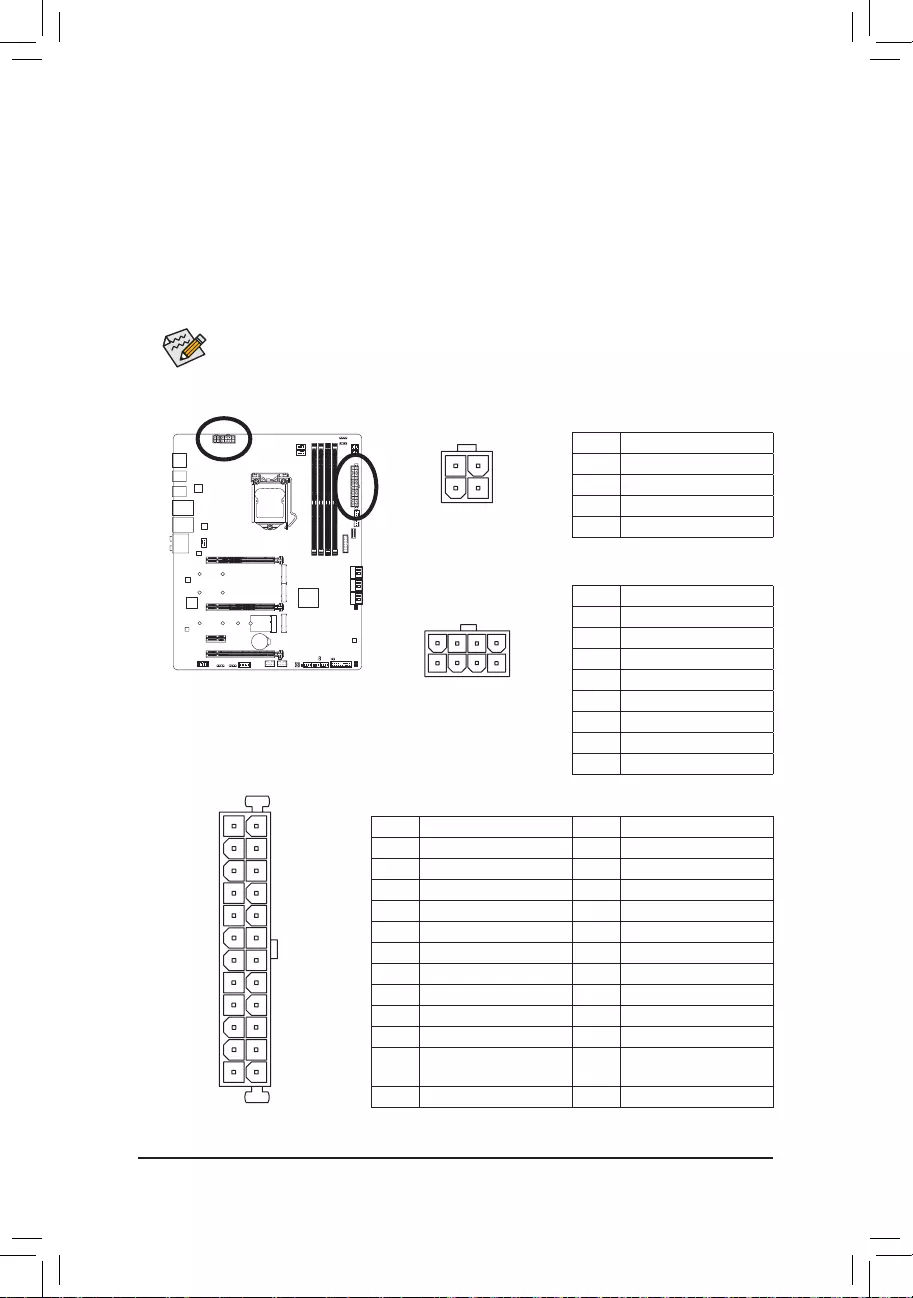
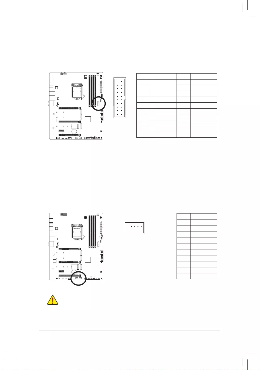
1/2) ATX_12V_2X2/ATX_12V_2X4/ATX (2×2, 2×4, 12V Power Connectors and 2×12 Main Power
Connector)
With the use of the power connector, the power supply can supply enough stable power to all the components
onthemotherboard.Beforeconnectingthepowerconnector,rstmakesurethepowersupplyisturned
off and all devices are properly installed. The power connector possesses a foolproof design. Connect the
power supply cable to the power connector in the correct orientation.
The 12V power connector mainly supplies power to the CPU. If the 12V power connector is not connected,
the computer will not start.
To meet expansion requirements, it is recommended that a power supply that can withstand high
power consumption be used (500W or greater). If a power supply is used that does not provide the
required power, the result can lead to an unstable or unbootable system.
ATX_12V_2X4
ATX_12V_2X4:
Pin No. Denition
1 GND (Only for 2×4-pin 12V)
2 GND (Only for 2×4-pin 12V)
3 GND
4 GND
5+12V (Only for 2×4-pin 12V)
6+12V (Only for 2×4-pin 12V)
7 +12V
8 +12V
ATX:
Pin No. Denition Pin No. Denition
1 3.3V 13 3.3V
2 3.3V 14 -12V
3 GND 15 GND
4 +5V 16 PS_ON(softOn/Off)
5 GND 17 GND
6 +5V 18 GND
7 GND 19 GND
8 Power Good 20 NC
9 5VSB (stand by +5V) 21 +5V
10 +12V 22 +5V
11 +12V (Only for 2×12-pin
ATX)
23 +5V (Only for 2×12-pin ATX)
12 3.3V (Only for 2×12-pin ATX) 24 GND (Only for 2×12-pin ATX)
41
85
131
2412
ATX
ATX_12V_2X2:
Pin No. Denition
1 GND
2 GND
3 +12V
4 +12V
ATX_12V_2X2
1
3
2
4
— 26 —
•Be sure to connect fan cables to the fan headers to prevent your CPU and system from
overheating. Overheating may result in damage to the CPU or the system may hang.
•Thesefanheadersarenotcongurationjumperblocks.Donotplaceajumpercapontheheaders.
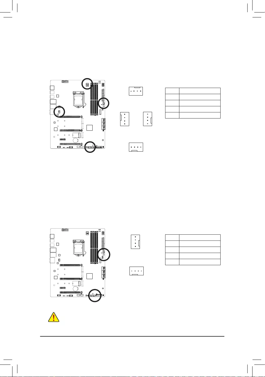
3/4) CPU_FAN/SYS_FAN1/2/3/4 (Fan Headers)
All fan headers on this motherboard are 4-pin. Most fan headers possess a foolproof insertion design.
When connecting a fan cable, be sure to connect it in the correct orientation (the black connector wire is
the ground wire). The speed control function requires the use of a fan with fan speed control design. For
optimum heat dissipation, it is recommended that a system fan be installed inside the chassis.
CPU_FAN
1
1
SYS_FAN3/SYS_FAN4
1
SYS_FAN2
1
SYS_FAN1
Pin No. Denition
1 GND
2 Voltage Speed Control
3 Sense
4 PWM Speed Control
5) SYS_FAN5/6_PUMP (System Fan/Water Cooling Pump Headers)
Thefan/pumpheadersare4-pin.Mostfanheaderspossessafoolproofinsertiondesign.Whenconnecting
a fan cable, be sure to connect it in the correct orientation (the black connector wire is the ground wire). The
speed control function requires the use of a fan with fan speed control design. For optimum heat dissipation,
it is recommended that a system fan be installed inside the chassis. The header also provides speed control
for a water cooling pump, refer to Chapter 2, «BIOS Setup,» «Smart Fan 6,» for more information.
Pin No. Denition
1 GND
2 Voltage Speed Control
3 Sense
4 PWM Speed Control
1
SYS_FAN6_PUMP
SYS_FAN5_PUMP
1
— 27 —
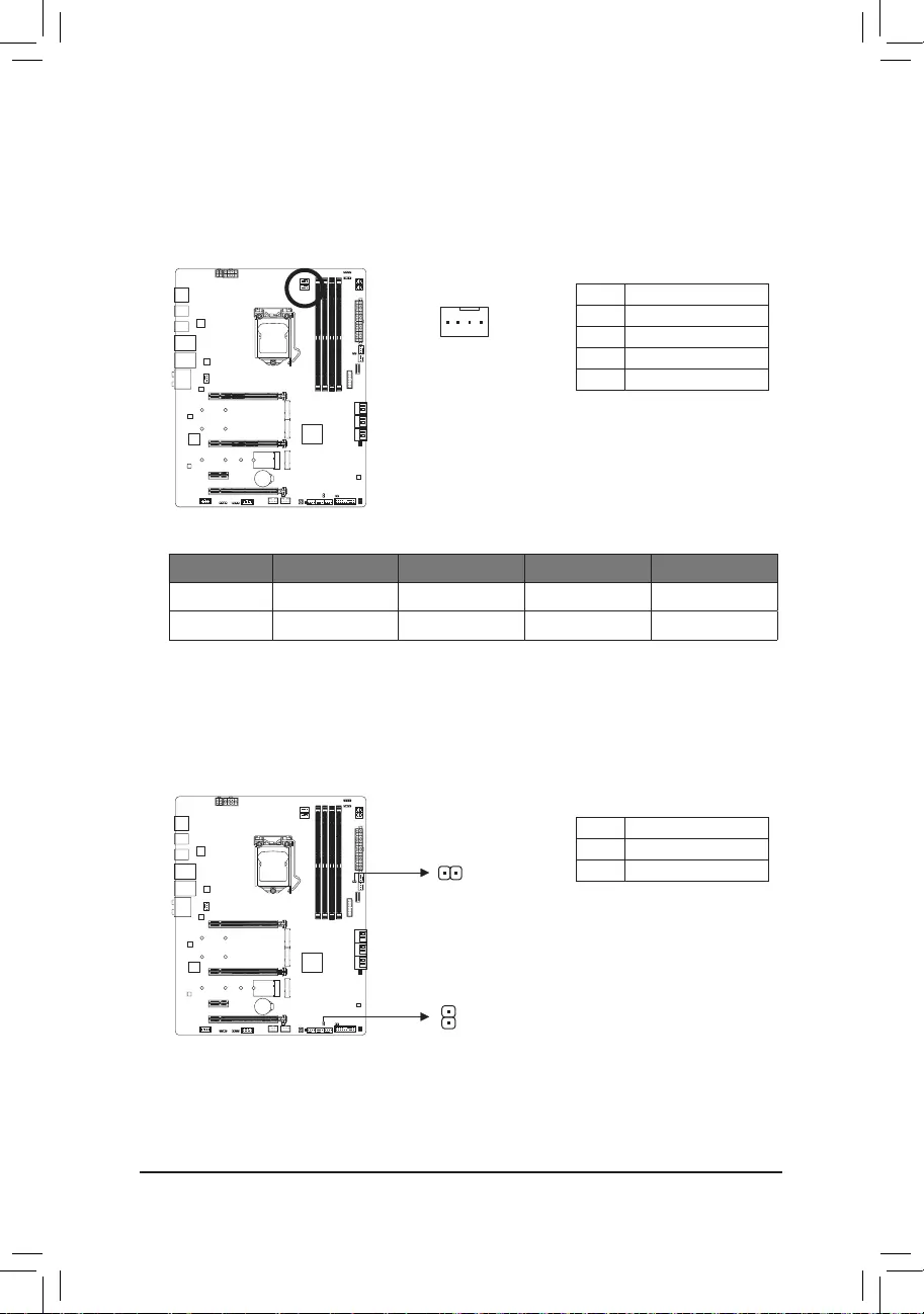
7) EC_TEMP1/EC_TEMP2 (Temperature Sensor Headers)
Connect the thermistor cables to the headers for temperature detection.
Pin No. Denition
1SENSORIN
2 GND
1
EC_TEMP2
EC_TEMP1
6) CPU_OPT (Water Cooling CPU Fan Header)
The fan header is 4-pin and possesses a foolproof insertion design. Most fan headers possess a foolproof
insertion design. When connecting a fan cable, be sure to connect it in the correct orientation (the black
connector wire is the ground wire). The speed control function requires the use of a fan with fan speed
control design.
1
Pin No. Denition
1 GND
2 Voltage Speed Control
3 Sense
4 PWM Speed Control
1
Connector CPU_FAN SYS_FAN1~4 SYS_FAN5/6_PUMP CPU_OPT
Maximum Current 2A 2A 2A 2A
Maximum Power 24W 24W 24W 24W
— 28 —
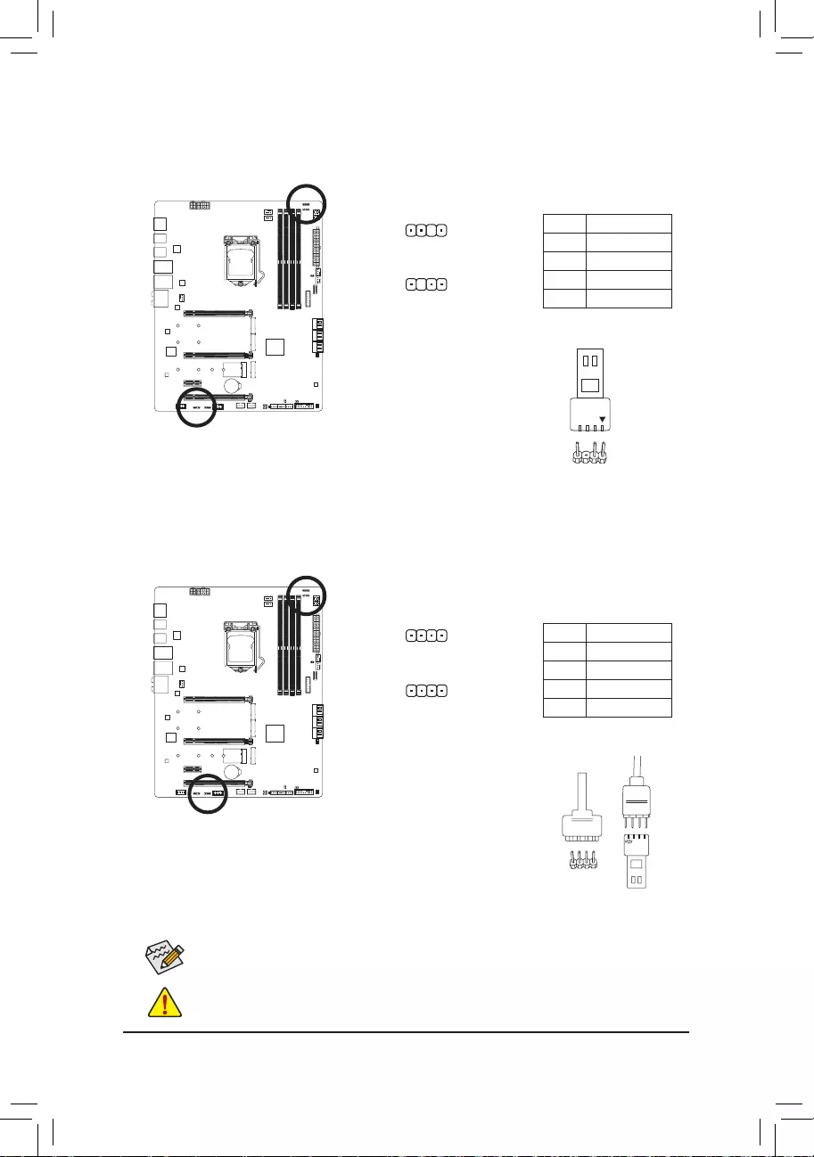
D_LED1/D_LED2 (Addressable LED Strip Headers)
The headers can be used to connect a standard 5050 addressable LED strip, with maximum power rating
of 5A (5V) and maximum number of 1000 LEDs.
Before installing the devices, be sure to turn off the devices and your computer. Unplug the power
cord from the power outlet to prevent damage to the devices.
Forhowtoturnon/offthelightsoftheLEDstrip,refertotheinstructionsoninChapter5,«Unique
Features,»»APPCenterRGBFusion.»
1
F_USB30 F_U
B_
F_ F_
_
B
BS_
B
SB_
B
_S
S_
_
B
_U
_
B
S
123
123
123
123
1
1
1
1
BSS
S
_S
SSU
1 2 3 4 5
S3 BSSS
U
__ 3
F_USB3F
S _
S _
S _
SF
B_
B_
F
_0
S
S
_0F
_F
_
_
__B
U
S _S
_ SF_
B
USB0_B
B_
B_
F_USB3
F_USB303
_
_3U
S_
D_LED1
Pin No. Denition
1 V (5V)
2 Data
3 No Pin
4 GND
Connect your addressable LED strip
to the header. The power pin (marked
with a triangle on the plug) of the LED strip must be connected to Pin 1 of
the addressable LED strip header. Incorrect connection may lead to the
damage of the LED strip.
1
F_USB30 F_U
B_
F_ F_
_
B
BS_
B
SB_
B
_S
S_
_
B
_U
_
B
S
123
123
123
123
1
1
1
1
BSS
S
_S
SSU
1 2 3 4 5
S3 BSSS
U
__ 3
F_USB3F
S _
S _
S _
SF
B_
B_
F
_0
S
S
_0F
_F
_
_
__B
U
S _S
_ SF_
B
USB0_B
B_
B_
F_USB3
F_USB303
_
_3U
S_
D_LED2
9) LED_C1/LED_C2 (RGB LED Strip Headers)
Theheaderscanbeusedtoconnectastandard5050RGBLEDstrip(12V/G/R/B),withmaximumpower
rating of 2A (12V) and maximum length of 2m.
ConnectoneendoftheRGBLEDstrip
extension cable to the header and the
otherendtoyourRGBLEDstrip.Theblackwire(markedwithatriangle
on the plug) of the extension cable must be connected to Pin 1 (12V) of
this header. The 12V pin (marked with an arrow) on the other end of the
extension cable must be lined up with the 12V of the LED strip. Be careful
with the connection orientation of the LED strip; incorrect connection may
lead to the damage of the LED strip.
12VRGB
12V
1
RGBLED
Strip
BG12VR
Pin No. Denition
1 12V
2 G
3R
4 B
1
LED_C2
1
LED_C1
Addressable LED
Strip
1
— 29 —
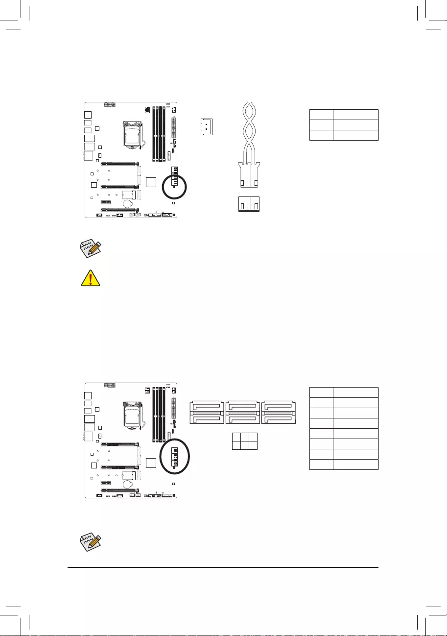
11) SATA3 0/1/2/3/4/5 (SATA 6Gb/s Connectors)
TheSATAconnectorsconformtoSATA6Gb/sstandardandarecompatiblewithSATA3Gb/sandSATA
1.5Gb/sstandard.EachSATAconnectorsupportsasingleSATAdevice.TheIntel®ChipsetsupportsRAID0,
RAID1,RAID5,andRAID10.RefertoChapter3,«ConguringaRAIDSet,»forinstructionsonconguring
aRAIDarray.
Pin No. Denition
1 GND
2 TXP
3 TXN
4 GND
5RXN
6RXP
7 GND
SATA3 5 3 1
4 2 0
To enable hot-plugging for the SATA ports, refer to Chapter 2, «BIOS Setup,» «SettingsIO Ports
SATAAndRSTConguration,»formoreinformation.
1
1
7
7
10) NOISE_SENSOR (Noise Detection Header)
This header can be used to connect a noise detection cable to detect the noise inside the case.
Pin No. Denition
1 Noise Detection
2 GND
1
Noise Detection
Cable
1
Before connecting the cable to the header, make sure to remove the jumper cap; re-place the
jumper cap if the header is not in use.
For more information on the noise detection function, refer to the instructions in Chapter 5, «Unique
Features,» «APP CenterSystem Information Viewer»
— 30 —
12) M2A_CPU (Note)/M2M_SB/M2P_SB (M.2 Socket 3 Connectors)
TheM.2connectorssupportM.2SATASSDsorM.2PCIeSSDsandsupportRAIDconguration.Please
notethatanM.2PCIeSSDcannotbeusedtocreateaRAIDseteitherwithanM.2SATASSDoraSATA
harddrive.RefertoChapter3,»ConguringaRAIDSet,»forinstructionsonconguringaRAIDarray.
Follow the steps below to correctly install an M.2 SSD in the M.2 connector.
Step 1:
Locate the M.2 connector where you will install the M.2 SSD, use a screwdriver to unfasten the screw on
theheatsinkandthenremovetheheatsink.RemovetheprotectivelmfromthethermalpadontheM.2
connector.
Step 2:
Locate the proper mounting hole based on the length of your M.2 SSD drive. If needed, move the standoff
to the desired mounting hole. Insert the M.2 SSD into the M.2 connector at an angle.
Step 3:
PresstheM.2SSDdownand thenusetheincludedscrew tosecureitintheconnector.Replacethe
heatsinkandsecureittotheoriginalhole.Removetheprotectivelmfromthebottomoftheheatsink
before replacing the heatsink.
(Note) Supported by 11th Generation processors only. Be sure to use Intel® SSDs if you want to set up a
RAIDcongurationontheM2A_CPUconnector.
F_USB30 F_U
B_
F_ F_
_
B
BS_
B
SB_
B
_S
S_
_
B
_U
_
B
S
123
123
123
123
1
1
1
1
BSS
S
_S
SSU
1 2 3 4 5
S3 BSSS
U
__ 3
F_USB3F
S _
S _
S _
SF
B_
B_
F
_0
S
S
_0F
_F
_
_
__B
U
S _S
_ SF_
B
USB0_B
B_
B_
F_USB3
F_USB303
_
_3U
S_
80110 60 42
F_USB30 F_U
B_
F_ F_
_
B
BS_
B
SB_
B
_S
S_
_
B
_U
_
B
S
123
123
123
123
1
1
1
1
BSS
S
_S
SSU
1 2 3 4 5
S3 BSSS
U
__ 3
F_USB3F
S _
S _
S _
SF
B_
B_
F
_0
S
S
_0F
_F
_
_
__B
U
S _S
_ SF_
B
USB0_B
B_
B_
F_USB3
F_USB303
_
_3U
S_
80110 60 42
M2A_CPU (Note)
M2M_SB
F_USB30 F_U
B_
F_ F_
_
B
BS_
B
SB_
B
_S
S_
_
B
_U
_
B
S
123
123
123
123
1
1
1
1
BSS
S
_S
SSU
1 2 3 4 5
S3 BSSS
U
__ 3
F_USB3F
S _
S _
S _
SF
B_
B_
F
_0
S
S
_0F
_F
_
_
__B
U
S _S
_ SF_
B
USB0_B
B_
B_
F_USB3
F_USB303
_
_3U
S_
80110 60 42
M2P_SB
— 31 —
•M2P_SB:
SATA3 0 SATA3 1 SATA3 2 SATA3 3 SATA3 4 SATA3 5 PCIEX4
M.2 PCIe SSD
aaaaaaa(Note 2)
No M.2 SSD Installed aaaaaaa
a: Available, r: Not available
* TheM2P_SBconnectorsupportsonlyPCIeSSDs.
Connector
Type of
M.2 SSD
Installation Notices for the PCIEX4, M.2 and SATA Connectors:
The availability of the SATA connectors may be affected by the type of device installed in the M.2 sockets.
The M2M_SB connector shares bandwidth with the SATA3 1 connector. The M2P_SB connector shares
bandwidthwiththePCIEX4slot.Refertothefollowingtablesfordetails.
•M2A_CPU (Note 1):
SATA3 0 SATA3 1 SATA3 2 SATA3 3 SATA3 4 SATA3 5
M.2PCIeSSD*
aaaaaa
No M.2 SSD Installed aaaaaa
a: Available, r: Not available
* TheM2A_CPUconnectorsupportsonlyPCIeSSDs.
Connector
Type of
M.2 SSD
•M2M_SB:
SATA3 0 SATA3 1 SATA3 2 SATA3 3 SATA3 4 SATA3 5
M.2 SATA SSD araaaa
M.2 PCIe SSD
aaaaaa
No M.2 SSD Installed aaaaaa
a: Available, r: Not available
Connector
Type of
M.2 SSD
(Note 1) Supported by 11th Generation processors only.
(Note 2) The PCIEX4 slot shares bandwidth with the M2P_SB connector. The PCIEX4 slot operates at up to
x2 mode when a PCIe SSD is installed in the M2P_SB connector.
— 32 —
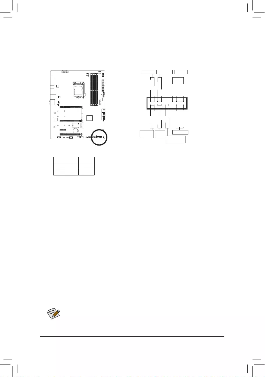
13) F_PANEL (Front Panel Header)
Connectthepowerswitch,resetswitch,speaker,chassisintrusionswitch/sensorandsystemstatusindicator
on the chassis to this header according to the pin assignments below. Note the positive and negative pins
before connecting the cables.
NC
NC
Power LED
1
2
19
20
CI-
CI+
PWR_LED-
PWR_LED+
PLED-
PW-
SPEAK+
SPEAK-
PLED+
PW+
Power LED
HD-
RES+
HD+
RES-
Hard Drive
Activity LED
Reset
Switch Chassis Intrusion
Header
Power Switch Speaker
PWR_LED-
The front panel design may differ by chassis. A front panel module mainly consists of power switch,
reset switch, power LED, hard drive activity LED, speaker and etc. When connecting your chassis
front panel module to this header, make sure the wire assignments and the pin assignments are
matched correctly.
•PW (Power Switch):
Connectstothepowerswitchonthechassisfrontpanel.Youmaycongurethewaytoturnoffyour
system using the power switch (refer to Chapter 2, «BIOS Setup,» «SettingsPlatform Power,» for more
information).
•SPEAK (Speaker):
Connects to the speaker on the chassis front panel. The system reports system startup status by issuing
a beep code. One single short beep will be heard if no problem is detected at system startup.
•HD (Hard Drive Activity LED):
Connects to the hard drive activity LED on the chassis front panel. The LED is on when the hard drive
is reading or writing data.
•RES (ResetSwitch):
Connects to the reset switch on the chassis front panel. Press the reset switch to restart the computer
ifthecomputerfreezesandfailstoperformanormalrestart.
•CI (Chassis Intrusion Header):
Connectstothechassisintrusionswitch/sensoronthechassisthatcandetectifthechassiscoverhas
beenremoved.Thisfunctionrequiresachassiswithachassisintrusionswitch/sensor.
•NC: No connection.
•PLED/PWR_LED (Power LED):
Connects to the power status indicator on the chassis front panel. The LED
isonwhenthesystemisoperating.TheLEDisoffwhenthesystemisinS3/
S4 sleep state or powered off (S5).
System Status LED
S0 On
S3/S4/S5 Off
— 33 —
14) F_AUDIO (Front Panel Audio Header)
ThefrontpanelaudioheadersupportsHighDenitionaudio(HD).Youmayconnectyourchassisfront
panel audio module to this header. Make sure the wire assignments of the module connector match the
pin assignments of the motherboard header. Incorrect connection between the module connector and the
motherboard header will make the device unable to work or even damage it.
Pin No. Denition
1 MIC2_L
2 GND
3MIC2_R
4 NC
5LINE2_R
6 Sense
7 GND
8 No Pin
9 LINE2_L
10 Sense
F_USB30 F_U
B_
F_ F_
_
B
BS_
B
SB_
B
_S
S_
_
B
_U
_
B
S
123
123
123
123
1
1
1
1
BSS
S
_S
SSU
1 2 3 4 5
S3 BSSS
U
__ 3
F_USB3F
S _
S _
S _
SF
B_
B_
F
_0
S
S
_0F
_F
_
_
__B
U
S _S
_ SF_
B
USB0_B
B_
B_
F_USB3
F_USB303
_
_3U
S_
9 1
10 2
Some chassis provide a front panel audio module that has separated connectors on each wire
instead of a single plug. For information about connecting the front panel audio module that has
different wire assignments, please contact the chassis manufacturer.
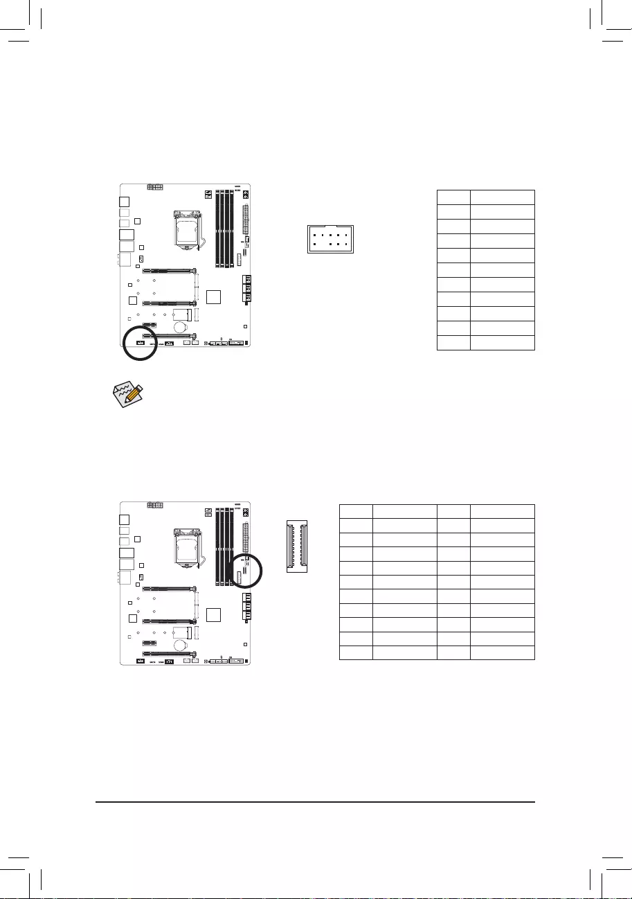
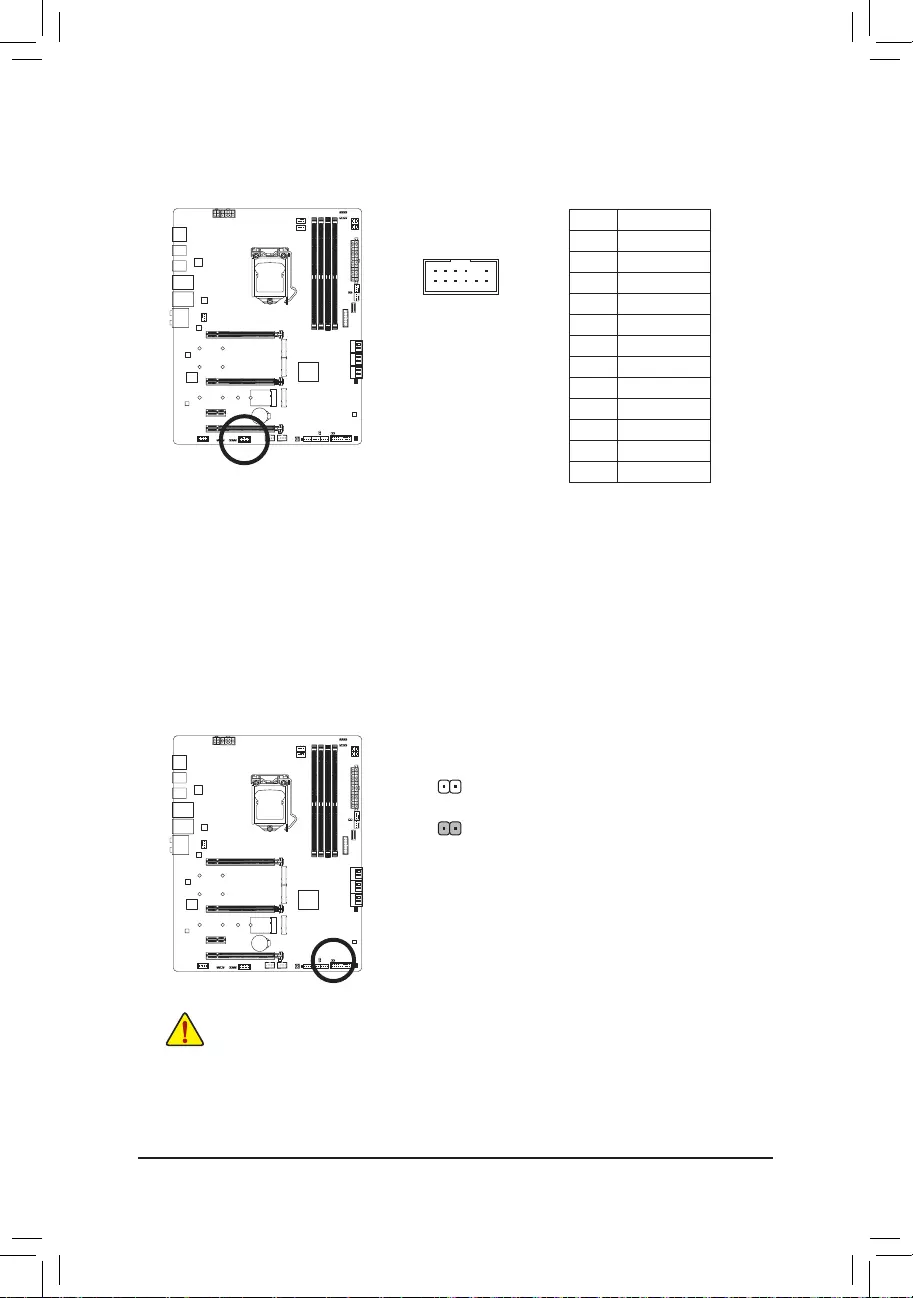
15) F_U320G (USB Type-C® Header with USB 3.2 Gen 2×2 Support)
TheheaderconformstoUSB3.2Gen2×2specicationandcanprovideoneUSBport.
Pin No. Denition Pin No. Denition
1 VBUS 11 VBUS
2 TX1+ 12 TX2+
3 TX1- 13 TX2-
4 GND 14 GND
5RX1+ 15 RX2+
6RX1- 16 RX2-
7 VBUS 17 GND
8 CC1 18 D-
9 SBU1 19 D+
10 SBU2 20 CC2
F_USB30 F_U
B_
F_ F_
_
B
BS_
B
SB_
B
_S
S_
_
B
_U
_
B
S
123
123
123
123
1
1
1
1
BSS
S
_S
SSU
1 2 3 4 5
S3 BSSS
U
__ 3
F_USB3F
S _
S _
S _
SF
B_
B_
F
_0
S
S
_0F
_F
_
_
__B
U
S _S
_ SF_
B
USB0_B
B_
B_
F_USB3
F_USB303
_
_3U
S_
20
10 11
1
— 34 —
16) F_U32 (USB 3.2 Gen 1 Header)
TheheaderconformstoUSB3.2Gen1andUSB2.0specicationandcanprovidetwoUSBports.For
purchasing the optional 3.5″ front panel that provides two USB 3.2 Gen 1 ports, please contact the local
dealer.
Pin No. Denition Pin No. Denition
1 VBUS 11 D2+
2SSRX1- 12 D2-
3SSRX1+ 13 GND
4 GND 14 SSTX2+
5 SSTX1- 15 SSTX2-
6SSTX1+ 16 GND
7 GND 17 SSRX2+
8 D1- 18 SSRX2-
9 D1+ 19 VBUS
10 NC 20 No Pin
F_USB30 F_U
B_
F_ F_
_
B
BS_
B
SB_
B
_S
S_
_
B
_U
_
B
S
123
123
123
123
1
1
1
1
BSS
S
_S
SSU
1 2 3 4 5
S3 BSSS
U
__ 3
F_USB3F
S _
S _
S _
SF
B_
B_
F
_0
S
S
_0F
_F
_
_
__B
U
S _S
_ SF_
B
USB0_B
B_
B_
F_USB3
F_USB303
_
_3U
S_
20 1
1011
17) F_USB1/F_USB2 (USB 2.0/1.1 Headers)
TheheadersconformtoUSB2.0/1.1specication.EachUSBheadercanprovidetwoUSBportsviaan
optional USB bracket. For purchasing the optional USB bracket, please contact the local dealer.
Pin No. Denition
1 Power (5V)
2 Power (5V)
3 USB DX-
4 USB DY—
5 USB DX+
6 USB DY+
7 GND
8 GND
9 No Pin
10 NC
10
9
2
1
•DonotplugtheIEEE1394bracket(2×5-pin)cableintotheUSB2.0/1.1header.
•Prior to installing the USB bracket, be sure to turn off your computer and unplug the power cord
from the power outlet to prevent damage to the USB bracket.
— 35 —
Pin No. Denition
1Data Output
2Power (3.3V)
3No Pin
4NC
5Data Input
6CLK
7Chip Select
8GND
9IRQ
10 NC
11 NC
12 RST
18) SPI_TPM (Trusted Platform Module Header)
You may connect an SPI TPM (Trusted Platform Module) to this header.
12
11
2
1
F_USB30 F_U
B_
F_ F_
_
B
BS_
B
SB_
B
_S
S_
_
B
_U
_
B
S
123
123
123
123
1
1
1
1
BSS
S
_S
SSU
1 2 3 4 5
S3 BSSS
U
__ 3
F_USB3F
S _
S _
S _
SF
B_
B_
F
_0
S
S
_0F
_F
_
_
__B
U
S _S
_ SF_
B
USB0_B
B_
B_
F_USB3
F_USB303
_
_3U
S_
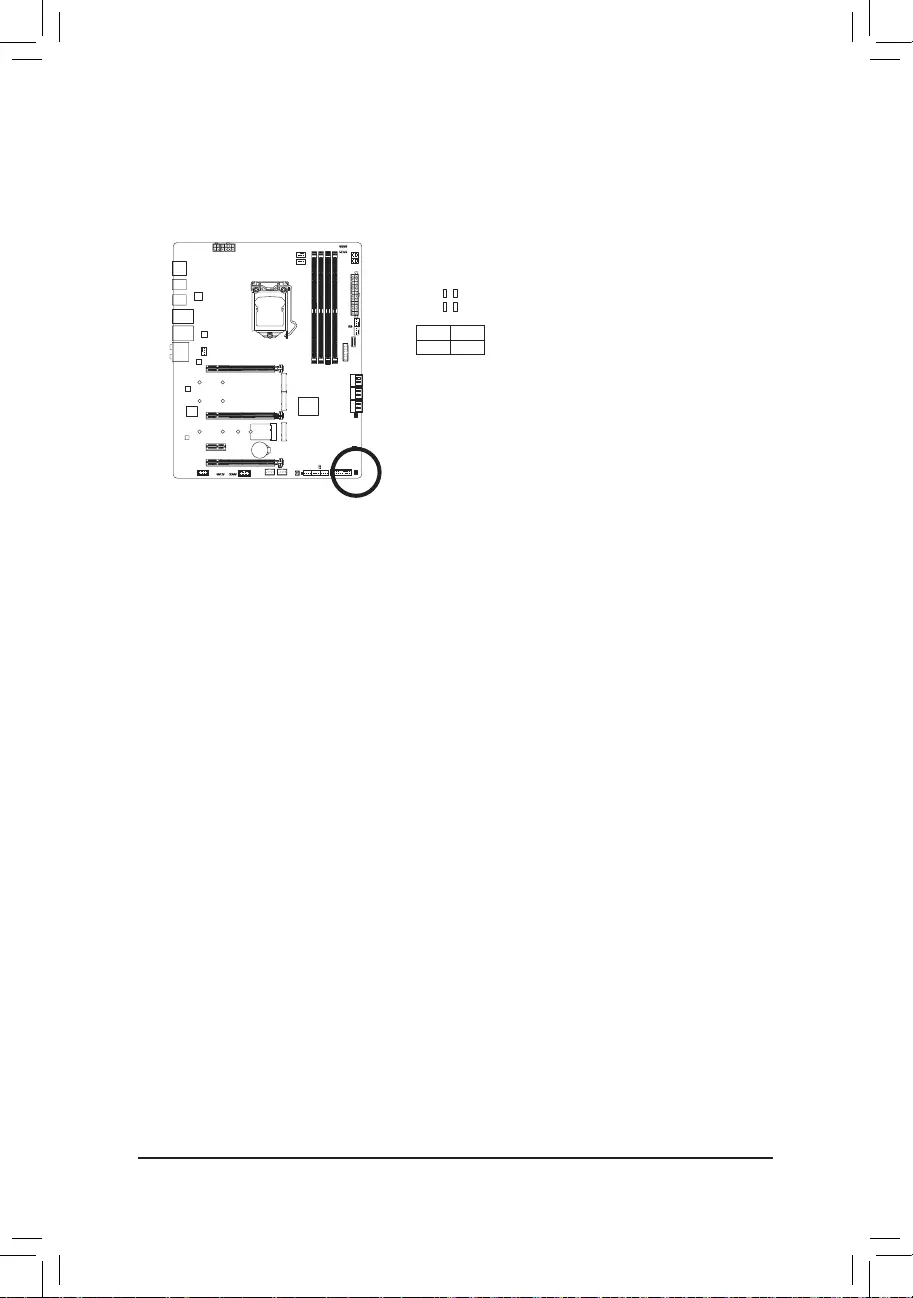
19) CLR_CMOS (Clear CMOS Jumper)
UsethisjumpertocleartheBIOScongurationandresettheCMOSvaluestofactorydefaults.Toclear
the CMOS values, use a metal object like a screwdriver to touch the two pins for a few seconds.
•Always turn off your computer and unplug the power cord from the power outlet before clearing
the CMOS values.
•Aftersystemrestart,gotoBIOSSetuptoloadfactorydefaults(selectLoadOptimizedDefaults)or
manuallyconguretheBIOSsettings(refertoChapter2,«BIOSSetup,»forBIOScongurations).
Open: Normal
Short: Clear CMOS Values
— 36 —
21) QFLASH_PLUS (Q-Flash Plus Button)
Q-Flash Plus allows you to update the BIOS when your system is off (S5 shutdown state). Save the latest
BIOSonaUSBthumbdriveandplugitintothededicatedport,andthenyoucannowashtheBIOS
automaticallybysimplypressingtheQ-FlashPlusbutton.TheQFLEDwillashwhentheBIOSmatching
andashingactivitiesstartandwillstopashingwhenthemainBIOSashingiscomplete.
To enable Q-Flash Plus function, refer to Chapter 5, «Unique Features,» for more information.
QFLASH_PLUS
QFLED
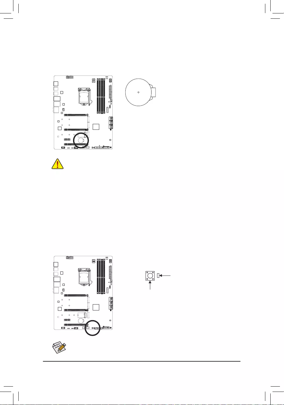
20) BAT (Battery)
Thebatteryprovidespowertokeepthevalues(suchasBIOScongurations,date,andtimeinformation)
intheCMOSwhenthecomputeristurnedoff.Replacethebatterywhenthebatteryvoltagedropstoalow
level, or the CMOS values may not be accurate or may be lost.
You may clear the CMOS values by removing the battery:
1. Turn off your computer and unplug the power cord.
2. Gently remove the battery from the battery holder and wait for one minute.
(Or use a metal object like a screwdriver to touch the positive and negative
terminals of the battery holder, making them short for 5 seconds.)
3. Replacethebattery.
4. Plug in the power cord and restart your computer.
•Always turn off your computer and unplug the power cord before replacing the battery.
•Replacethebatterywithanequivalentone.Damagetoyourdevicesmayoccurifthebatteryis
replaced with an incorrect model.
•Contact the place of purchase or local dealer if you are not able to replace the battery by yourself
or uncertain about the battery model.
•When installing the battery, note the orientation of the positive side (+) and the negative side (-)
of the battery (the positive side should face up).
•Used batteries must be handled in accordance with local environmental regulations.
— 37 —
22) CPU/DRAM/VGA/BOOT (Status LEDs)
The status LEDs show whether the CPU, memory, graphics card, and operating system are working
properlyaftersystempower-on.IftheCPU/DRAM/VGALEDison,thatmeansthecorrespondingdevice
is not working normally; if the BOOT LED is on, that means you haven’t entered the operating system yet.
CPU: CPU status LED
DRAM: Memory status LED
VGA: Graphics card status LED
BOOT: Operating system status LED
F_USB30 F_U
B_
F_ F_
_
B
BS_
B
SB_
B
_S
S_
_
B
_U
_
B
S
123
123
123
123
1
1
1
1
BSS
S
_S
SSU
1 2 3 4 5
S3 BSSS
U
__ 3
F_USB3F
S _
S _
S _
SF
B_
B_
F
_0
S
S
_0F
_F
_
_
__B
U
S _S
_ SF_
B
USB0_B
B_
B_
F_USB3
F_USB303
_
_3U
S_
CPU DRAM
VGA BOOT

— 38 —

— 39 —
BIOS (Basic Input and Output System) records hardware parameters of the system in the CMOS on the
motherboard. Its major functions include conducting the Power-On Self-Test (POST) during system startup,
saving system parameters and loading operating system, etc. BIOS includes a BIOS Setup program that allows
theusertomodifybasicsystemcongurationsettingsortoactivatecertainsystemfeatures.
When the power is turned off, the battery on the motherboard supplies the necessary power to the CMOS to
keepthecongurationvaluesintheCMOS.
To access the BIOS Setup program, press the <Delete> key during the POST when the power is turned on.
To upgrade the BIOS, use either the GIGABYTE Q-Flash or @BIOS utility.
•Q-Flash allows the user to quickly and easily upgrade or back up BIOS without entering the operating system.
•@BIOS is a Windows-based utility that searches and downloads the latest version of BIOS from the Internet
and updates the BIOS.
For instructions on using the Q-Flash and @BIOS utilities, refer to Chapter 5, «BIOS Update Utilities.»
Chapter 2 BIOS Setup
•BecauseBIOSashingispotentially risky,ifyoudonot encounter problemsusingthecurrent
versionofBIOS,itisrecommendedthatyounot ashtheBIOS.ToashtheBIOS,doitwith
caution.InadequateBIOSashingmayresultinsystemmalfunction.
•It is recommended that you not alter the default settings (unless you need to) to prevent system
instability or other unexpected results. Inadequately altering the settings may result in system’s
failure to boot. If this occurs, try to clear the CMOS values and reset the board to default values.
(Refertothe»LoadOptimizedDefaults»sectioninthischapterorintroductionsofthebattery/clear
CMOS jumper in Chapter 1 for how to clear the CMOS values.)

— 40 —
2-1 Startup Screen
The following startup Logo screen will appear when the computer boots.
Function Keys:
<DEL>: BIOS SETUPQ-FLASH
Press the <Delete> key to enter BIOS Setup or to access the Q-Flash utility in BIOS Setup.
<F12>: BOOT MENU
BootMenuallowsyoutosettherstbootdevicewithoutenteringBIOSSetup.InBootMenu,usetheup
arrow key <h> or the down arrow key <i>toselecttherstbootdevice,thenpress<Enter>toaccept.
The system will boot from the device immediately.
Note: The setting in Boot Menu is effective for one time only. After system restart, the device boot order
will still be based on BIOS Setup settings.
<END>: Q-FLASH
Pressthe<End>keytoaccesstheQ-FlashutilitydirectlywithouthavingtoenterBIOSSetuprst.
Function Keys
— 41 —
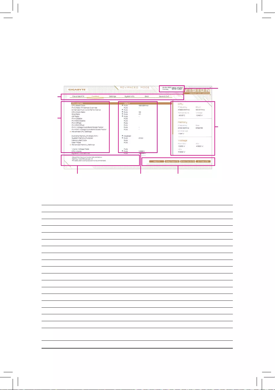
2-2 The Main Menu
Advanced Mode
The Advanced Mode provides detailed BIOS settings. You can press the arrow keys on your keyboard to move
among the items and press <Enter> to accept or enter a sub-menu. Or you can use your mouse to select the
item you want.
Hardware
Information
CongurationItems Current Settings
Setup Menus
Conguration
Items
System Time
Quick Access Bar allows you to quickly move to
the General Help, Easy Mode, Smart Fan 6, or
Q-Flash screen.
Advanced Mode Function Keys
<f><g> Move the selection bar to select a setup menu
<h><i>Movetheselectionbartoselectancongurationitemonamenu
<Enter>/DoubleClick Execute command or enter a menu
<+>/<PageUp> Increase the numeric value or make changes
<—>/<PageDown> Decrease the numeric value or make changes
<F1> Show descriptions of the function keys
<F2> Switch to Easy Mode
<F3> SavethecurrentBIOSsettingstoaprole
<F4> LoadtheBIOSsettingsfromaprolecreatedbefore
<F5> RestorethepreviousBIOSsettingsforthecurrentsubmenus
<F6> Display the Smart Fan 6 screen
<F7> LoadtheOptimizedBIOSdefaultsettingsforthecurrentsubmenus
<F8> Access the Q-Flash utility
<F10> Save all the changes and exit the BIOS Setup program
<F11> Switch to the Favorites submenu
<F12> Capture the current screen as an image and save it to your USB drive
<Insert> Add or remove a favorite option
<Ctrl>+<S> Display information on the installed memory
<Esc> Main Menu: Exit the BIOS Setup program
Submenus: Exit current submenu
— 42 —
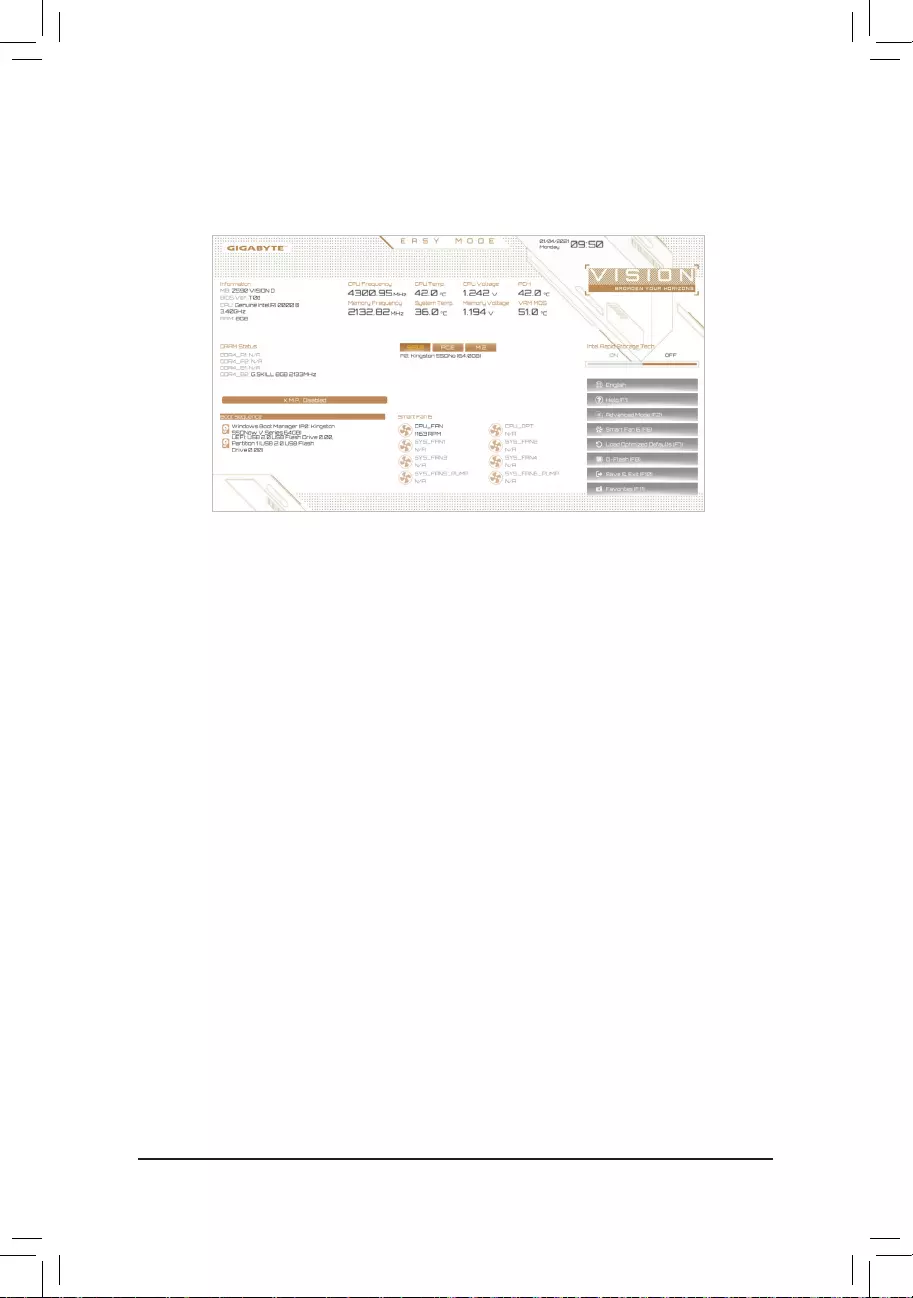
B. Easy Mode
Easy Mode allows users to quickly view their current system information or to make adjustments for optimum
performance.InEasyMode,youcanuseyourmousetomovethroughcongurationitemsorpress<F2>to
switch to the Advanced Mode screen.
— 43 —
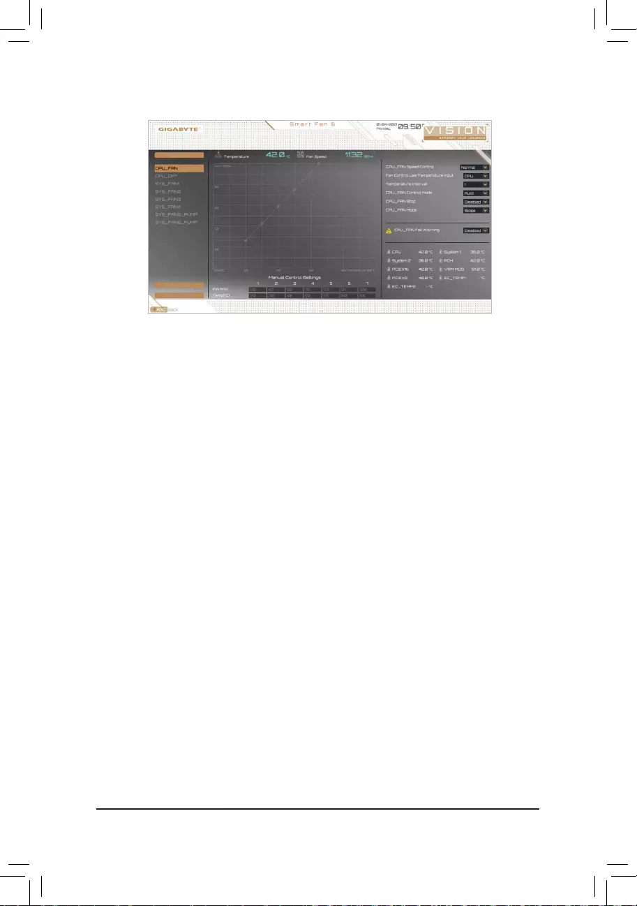
Usethe<F6>functionkeytoquicklyswitchtothisscreen.Thisscreenallowsyoutocongurefanspeedrelated
settingsforeachfanheaderormonitoryoursystem/CPUtemperature.
&TUNE ALL
Allows you to apply the current settings to all fan headers.
&Temperature
Displays the current temperature of the selected target area.
&Fan Speed
Displayscurrentfan/pumpspeeds.
&Flow Rate
Displaystheowrateofyourwatercoolingsystem.Press<Enter>onFan Speed to switch to this function.
&Fan Speed Control
Allows you to determine whether to enable the fan speed control function and adjust the fan speed.
Normal Allows the fan to run at different speeds according to the temperature. You can adjust
the fan speed with System Information Viewer based on your system requirements.
(Default)
Silent Allows the fan to run at slow speeds.
Manual Allows you to drag the curve nodes to adjust fan speed. Or you can use the EZ Tuning
feature. After adjusting the node position, press Apply to automatically calculate the
slope of the curve.
Full Speed Allows the fan to run at full speeds.
&Fan Control Use Temperature Input
Allows you to select the reference temperature for fan speed control.
&Temperature Interval
Allows you to select the temperature interval for fan speed change.
&FAN/PUMP Control Mode
Auto Lets the BIOS automatically detect the type of fan installed and sets the optimal control
mode. (Default)
Voltage Voltagemodeisrecommendedfora3-pinfan/pump.
PWM PWMmodeisrecommendedfora4-pinfan/pump.
2-3 Smart Fan 6

— 44 —
&FAN/PUMP Stop
Enablesordisablesthefan/pumpstopfunction.Youcansetthetemperaturelimitusingthetemperature
curve. The fan or pump stops operation when the temperature is lower than the limit. (Default: Disabled)
&FAN/PUMP Mode
Allows you to set the operating mode for the fan.
Slope Adjusts the fan speed linearly based on the temperature. (Default)
Stair Adjusts the fan speed stepwise based on the temperature.
&FAN/PUMP Fail Warning
Allowsthesystemtoemitwarningsoundifthefan/pumpisnotconnectedorfails.Checkthefan/pump
conditionorfan/pumpconnectionwhenthisoccurs.(Default:Disabled)
&SaveFanProle
Thisfunctionallowsyoutosavethecurrentsettingstoaprole.YoucansavetheproleintheBIOSor
select Select File in HDD/FDD/USBtosavetheproletoyourstoragedevice.
&LoadFanProle
ThisfunctionallowsyoutoloadapreviouslysavedBIOSprolewithoutthehasslesofreconguringthe
BIOS settings. Or you can select Select File in HDD/FDD/USBtoloadaprolefromyourstoragedevice.
— 45 —
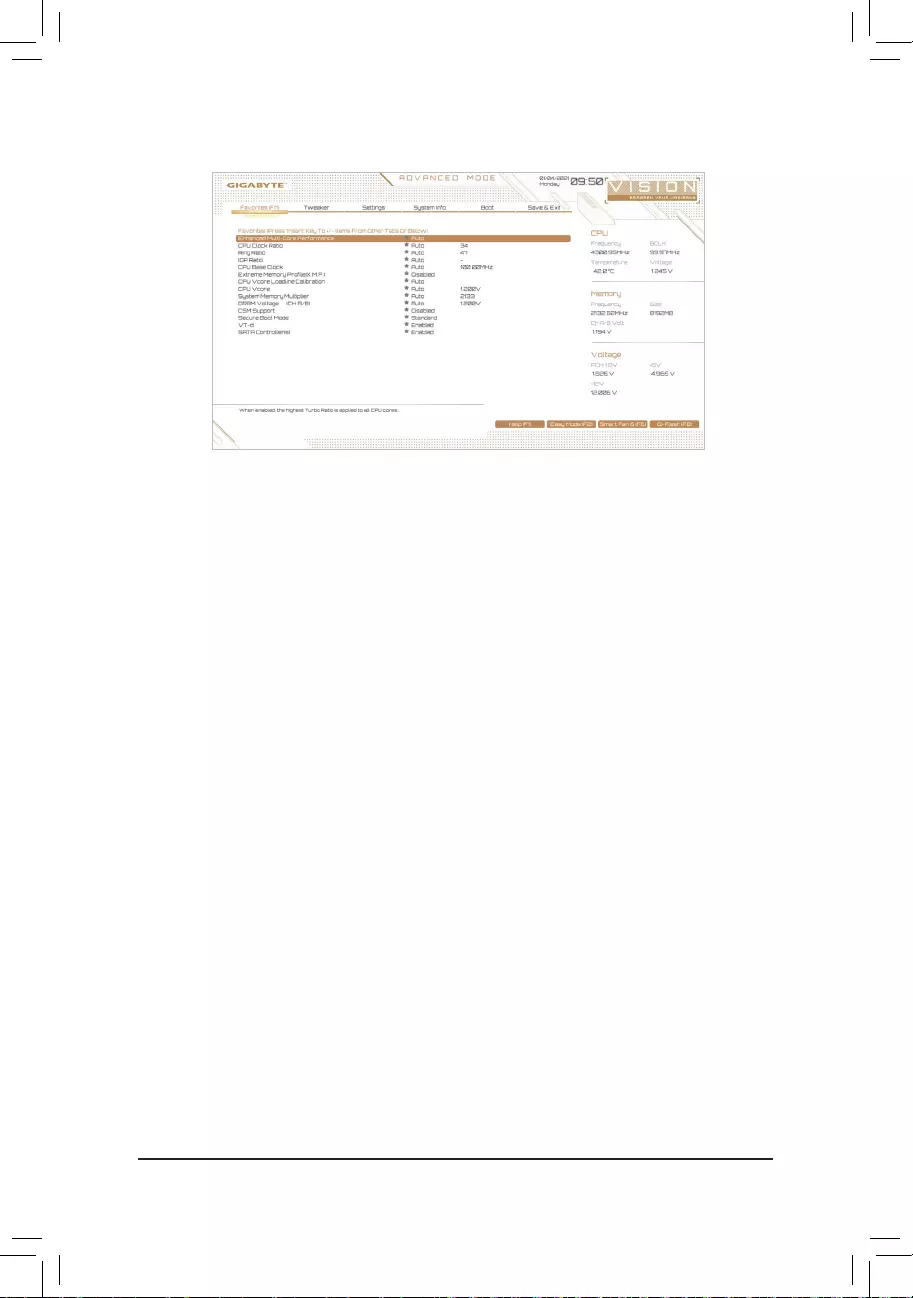
2-4 Favorites (F11)
Set your frequently used options as your favorites and use the <F11> key to quickly switch to the page where
all of your favorite options are located. To add or remove a favorite option, go to its original page and press
<Insert> on the option. The option is marked with a star sign if set as a «favorite.»
— 46 —
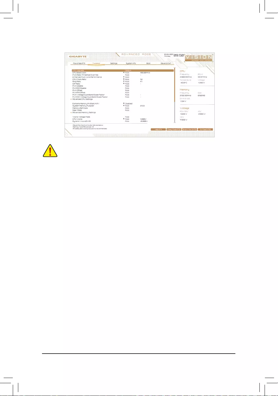
2-5 Tweaker
&CPU Upgrade
AllowsyoutosettheCPUfrequency.ThenalresultmayvarydependingontheCPUused.Optionsare:
Default,GamingProle,AdvancedProle.(Default:Default)
&CPU Base Clock
AllowsyoutomanuallysettheCPUbaseclockin0.01MHzincrements.(Default:Auto)
Important: It is highly recommended that the CPU frequency be set in accordance with the CPU
specications.
&PVD Ratio Threshold Override (Note)
Allows you to determine whether to improve performance under extreme BCLK OC by reducing a “PLL
Banding” condition caused in part by a very high DCO frequency. (Default: Auto)
&Enhanced Multi-Core Performance
Determines whether to allow the CPU to run at Turbo 1C speed. (Default: Auto)
&CPU Clock Ratio
Allows you to alter the clock ratio for the installed CPU. The adjustable range is dependent on the CPU
being installed.
&Ring Ratio
Allows you to set the CPU Uncore ratio. The adjustable range is dependent on the CPU being used. (Default:
Auto)
&IGP Ratio (Note)
AllowsyoutosettheGraphicsRatio.(Default:Auto)
Whetherthesystemwillworkstablywiththeoverclock/overvoltagesettingsyoumadeisdependent
onyouroverallsystemcongurations.Incorrectlydoingoverclock/overvoltagemayresultindamage
to CPU, chipset, or memory and reduce the useful life of these components. This page is for advanced
users only and we recommend you not to alter the default settings to prevent system instability or
other unexpected results. (Inadequately altering the settings may result in system’s failure to boot. If
this occurs, clear the CMOS values and reset the board to default values.)
(Note) This item is present only when you install a CPU that supports this feature. For more information about
Intel® CPUs’ unique features, please visit Intel’s website.
— 47 —
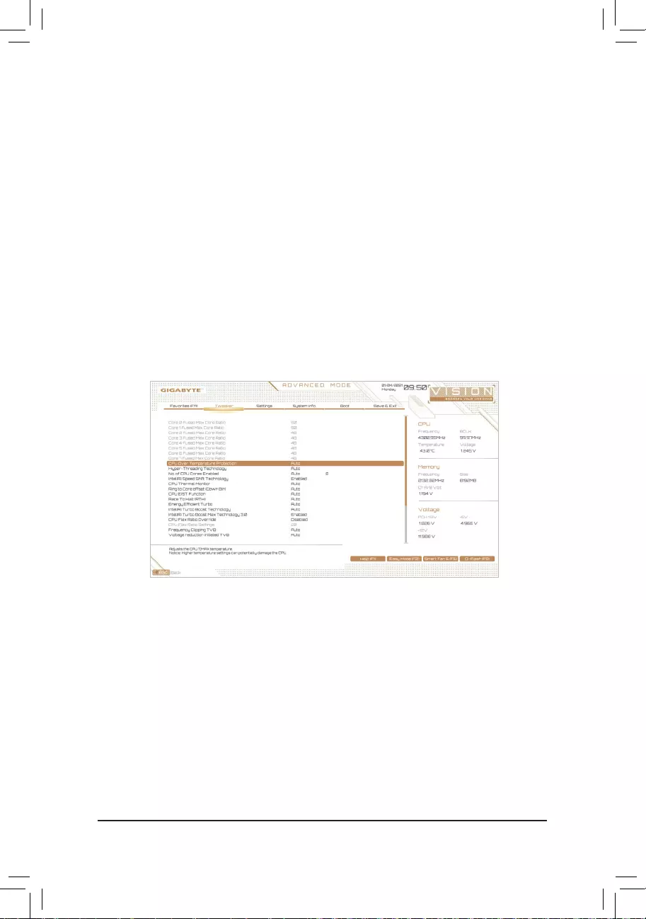
&Core Fused Max Core Ratio (Note)
Displays the highest frequency of each core.
&CPU Over Temperature Protection (Note)
Allowsyoutone-tunetheTJMaxoffsetvalue.(Default:Auto)
&FCLK Frequency for Early Power On (Note)
AllowsyoutosettheFCLKfrequency.Optionsare:Normal(800Mhz),1GHz,400MHz.(Default:1GHz)
&Hyper-Threading Technology
Allows you to determine whether to enable multi-threading technology when using an Intel® CPU that
supports this function. This feature only works for operating systems that support multi-processor mode.
AutoletstheBIOSautomaticallycongurethissetting.(Default:Auto)
Advanced CPU Settings
(Note) This item is present only when you install a CPU that supports this feature. For more information about
Intel® CPUs’ unique features, please visit Intel’s website.
&AVX Disable (Note)
Allows you to disable the AVX instruction sets on a CPU that supports AVX. (Default: Auto)
&AVX512 Disable (Note)
Allows you to disable the AVX-512 instruction sets on a CPU that supports AVX-512. (Default: Auto)
&AVX Offset (Note)
WhentheprocessorrunsAVXworkloads,theCPUClockRatiowillbereducedbythedesiredAVXoffsetvalue.
Forexample,ifthevalueissetto3,theCPUClockRatiowillbereducedby3whenexecutingAVXinstructions.
(Default: Auto)
&AVX512 Offset (Note)
WhentheprocessorrunsAVX-512workloads,theCPUClockRatiowillbereducedbythedesiredAVX-512
offset value. For example, if the value is set to 3 (the value must be larger than or equal to the AVX Offset
value),theCPUClockRatiowillbereducedby3whenexecutingAVX-512instructions.(Default:Auto)
&AVX Voltage Guardband Scale Factor (Note)
Allows you to lower the standard AVX voltage. (Default: Auto)
&AVX512 Voltage Guardband Scale Factor (Note)
Allows you to lower the standard AVX-512 voltage. (Default: Auto)

— 48 —
&No. of CPU Cores Enabled
Allows you to select the number of CPU cores to enable in an Intel® multi-core CPU (the number of CPU
cores may vary by CPU). AutoletstheBIOSautomaticallycongurethissetting.(Default:Auto)
&Intel(R) Speed Shift Technology (Intel® Speed Shift Technology) (Note)
Enables or disables Intel® Speed Shift Technology. Enabling this feature allows the processor to ramp up
its operating frequency more quickly and then improves the system responsiveness. (Default: Enabled)
&CPU Thermal Monitor (Note)
Enables or disables Intel® Thermal Monitor function, a CPU overheating protection function. When enabled,
the CPU core frequency and voltage will be reduced when the CPU is overheated. Auto lets the BIOS
automaticallycongurethissetting.(Default:Auto)
&Ring to Core offset (Down Bin)
AllowsyoutodeterminewhethertodisabletheCPURingratioauto-downfunction.Auto lets the BIOS
automaticallycongurethissetting.(Default:Auto)
&CPU EIST Function (Note)
Enables or disables Enhanced Intel® Speed Step Technology (EIST). Depending on CPU loading, Intel®
EIST technology can dynamically and effectively lower the CPU voltage and core frequency to decrease
average power consumption and heat production. AutoletstheBIOSautomaticallycongurethissetting.
(Default: Auto)
&Race To Halt (RTH) (Note)/EnergyEfcientTurbo (Note)
Enables or disables the CPU power saving related settings. (Default: Auto)
&Intel(R) Turbo Boost Technology (Note)
Allows you to determine whether to enable the Intel® CPU Turbo Boost technology. Auto lets the BIOS
automaticallycongurethissetting.(Default:Auto)
&Intel(R) Turbo Boost Max Technology 3.0 (Note)
Enables or disables Intel® Turbo Boost Max Technology 3.0. Intel® Turbo Boost Max Technology 3.0 allows
the system to identify the processor’s best performance core and lets you manually direct the most critical
workloadstoit.Youcanevenadjustthefrequencyofeachcoreindividuallyforperformanceoptimization.
(Default: Enabled)
&CPU Flex Ratio Override
EnablesordisablestheCPUFlexRatio.ThemaximumCPUclockratiowillbebasedontheCPU Flex
Ratio Settings value if CPU Clock Ratio is set to Auto. (Default: Disabled)
&CPU Flex Ratio Settings
AllowsyoutosettheCPUFlexRatio.TheadjustablerangemayvarybyCPU.
&Frequency Clipping TVB (Note)
Allows you to enable or disable automatic CPU frequency reduction initiated by Thermal Velocity Boost.
AutoletstheBIOSautomaticallycongurethissetting.(Default:Auto)
&Voltage reduction initiated TVB (Note)
Allows you to enable or disable automatic CPU voltage reduction initiated by Thermal Velocity Boost. Auto
letstheBIOSautomaticallycongurethissetting.(Default:Auto)
(Note) This item is present only when you install a CPU that supports this feature. For more information about
Intel® CPUs’ unique features, please visit Intel’s website.

— 49 —
dActive Turbo Ratios
&Turbo Ratio (Core Active)
Allows you to set the CPU Turbo ratios for different number of active cores. Auto sets the CPU Turbo ratios
accordingtotheCPUspecications.ThisitemiscongurableonlywhenActive Turbo Ratios is set to
Manual. (Default: Auto)
dPer Core HT Disable Setting
&HT Disable (Note)
AllowsyoutodeterminewhethertodisabletheHTfeatureforeachCPUcore.Thisitemiscongurable
only when Per Core HT Disable Setting is set to Manual. (Default: Disabled)
dC-States Control
&CPU Enhanced Halt (C1E)
Enables or disables Intel
®
CPU Enhanced Halt (C1E) function, a CPU power-saving function in system halt state.
When enabled, the CPU core frequency and voltage will be reduced during system halt state to decrease
power consumption. AutoletstheBIOSautomaticallycongurethissetting.Thisitemiscongurableonly
when C-States Control is set to Enabled. (Default: Auto)
&C3 State Support (Note)
Allows you to determine whether to let the CPU enter C3 mode in system halt state. When enabled, the
CPU core frequency and voltage will be reduced during system halt state to decrease power consumption.
The C3 state is a more enhanced power-saving state than C1. AutoletstheBIOSautomaticallycongure
thissetting.ThisitemiscongurableonlywhenC-States Control is set to Enabled. (Default: Auto)
&C6/C7 State Support
AllowsyoutodeterminewhethertolettheCPUenterC6/C7modeinsystemhaltstate.Whenenabled,the
CPU core frequency and voltage will be reduced during system halt state to decrease power consumption.
TheC6/C7stateisamoreenhancedpower-savingstatethanC3.AutoletstheBIOSautomaticallycongure
thissetting.ThisitemiscongurableonlywhenC-States Control is set to Enabled. (Default: Auto)
&C8 State Support (Note)
Allows you to determine whether to let the CPU enter C8 mode in system halt state. When enabled, the CPU
core frequency and voltage will be reduced during system halt state to decrease power consumption. The
C8stateisamoreenhancedpower-savingstatethanC6/C7.AutoletstheBIOSautomaticallycongure
thissetting.ThisitemiscongurableonlywhenC-States Control is set to Enabled. (Default: Auto)
&C10 State Support (Note)
Allows you to determine whether to let the CPU enter C10 mode in system halt state. When enabled, the
CPU core frequency and voltage will be reduced during system halt state to decrease power consumption.
The C10 state is a more enhanced power-saving state than C8. AutoletstheBIOSautomaticallycongure
thissetting.ThisitemiscongurableonlywhenC-States Control is set to Enabled. (Default: Auto)
&Package C State limit (Note)
Allows you to specify the C-state limit for the processor. AutoletstheBIOSautomaticallycongurethis
setting.ThisitemiscongurableonlywhenC-States Control is set to Enabled. (Default: Auto)
(Note) This item is present only when you install a CPU that supports this feature. For more information about
Intel® CPUs’ unique features, please visit Intel’s website.

— 50 —
dTurbo Power Limits
Allows you to set a power limit for CPU Turbo mode. When the CPU power consumption exceeds the
speciedpowerlimit,theCPUwillautomaticallyreducethecorefrequencyinordertoreducethepower.
AutosetsthepowerlimitaccordingtotheCPUspecications.(Default:Auto)
&Power Limit TDP (Watts) / Power Limit Time
AllowsyoutosetthepowerlimitformemoryTurbomodeandhowlongittakestooperateatthespecied
power limit. AutosetsthepowerlimitaccordingtotheCPUspecications.Thisitemiscongurableonly
when Turbo Power Limits is set to Enabled. (Default: Auto)
&Core Current Limit (Amps)
AllowsyoutosetacurrentlimitforCPUTurbomode.WhentheCPUcurrentexceedsthespeciedcurrent
limit, the CPU will automatically reduce the core frequency in order to reduce the current. Auto sets the
powerlimitaccordingtotheCPUspecications.ThisitemiscongurableonlywhenTurbo Power Limits
is set to Enabled. (Default: Auto)
dTurbo Per Core Limit Control (Note)
Allows you to control each CPU core limit separately. (Default: Auto)
&ExtremeMemoryProle(X.M.P.) (Note)
Allows the BIOS to read the SPD data on XMP memory module(s) to enhance memory performance when
enabled.
Disabled Disables this function. (Default)
Prole1 UsesProle1settings.
Prole2(Note) UsesProle2settings.
&System Memory Multiplier
Allows you to set the system memory multiplier. Auto sets memory multiplier according to memory SPD
data. (Default: Auto)
&Memory Ref Clock
Allows you to manually adjust the memory reference clock. (Default: Auto)
&Memory Odd Ratio (100/133 or 200/266) (Note)
Enabled allows Qclk to run in odd frequency. (Default: Auto)
&Gear Mode (Note)
Allows you to improve the maximum OC frequency potential. (Default: Auto)
(Note) This item is present only when you install a CPU and a memory module that support this feature.
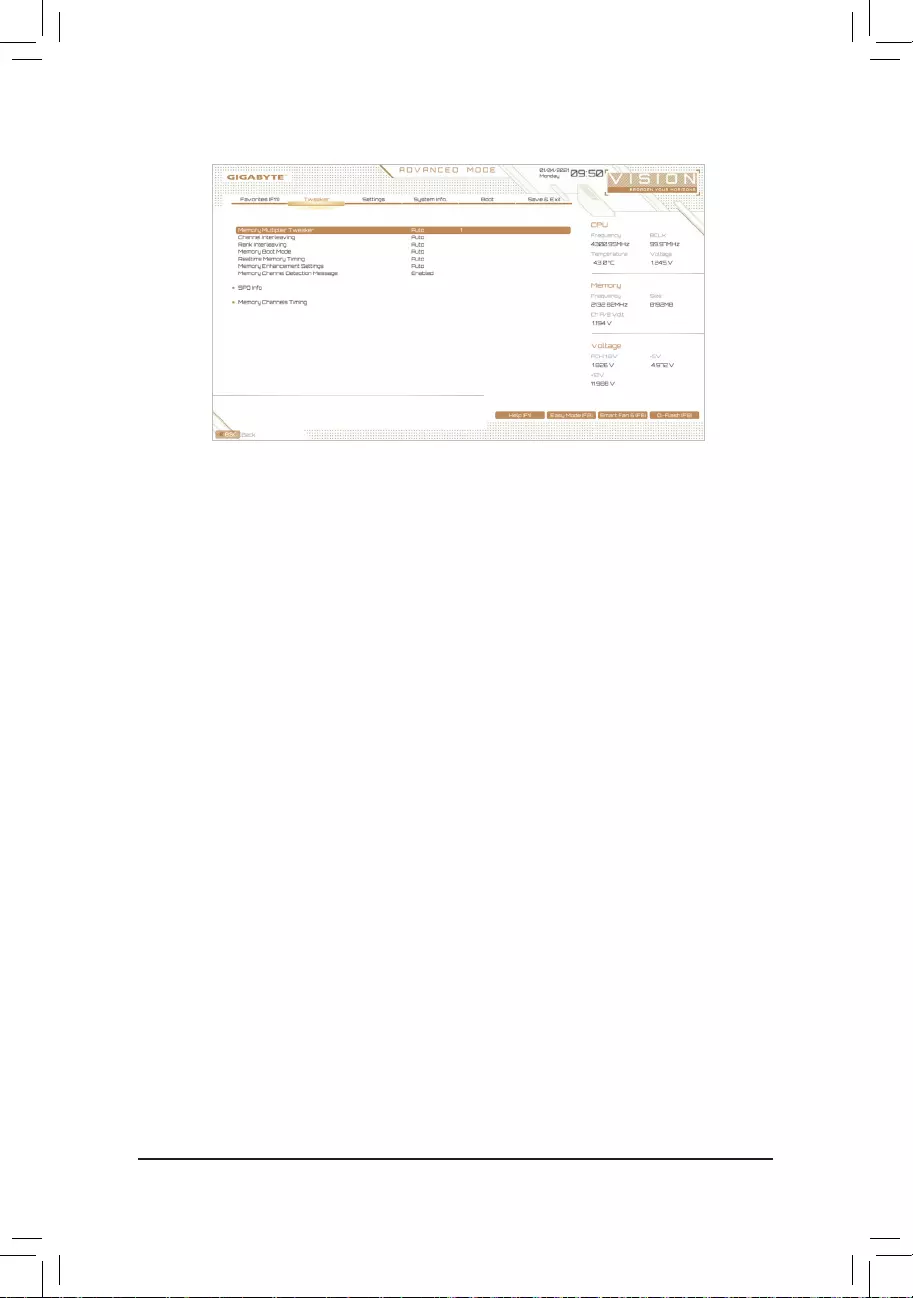
— 51 —
Advanced Memory Settings
&Memory Multiplier Tweaker
Provides different levels of memory auto-tuning. (Default: Auto)
&Channel Interleaving
Enables or disables memory channel interleaving. Enabled allows the system to simultaneously access
different channels of the memory to increase memory performance and stability. Auto lets the BIOS
automaticallycongurethissetting.(Default:Auto)
&Rank Interleaving
Enables or disables memory rank interleaving. Enabled allows the system to simultaneously access different
ranks of the memory to increase memory performance and stability. Auto lets the BIOS automatically
congurethissetting.(Default:Auto)
&Memory Boot Mode
Provides memory detection and training methods.
Auto LetstheBIOSautomaticallycongurethissetting.(Default)
Normal The BIOS automatically performs memory training. Please note that if the system
becomes unstable or unbootable, try to clear the CMOS values and reset the board
todefaultvalues.(Refertotheintroductionsofthebattery/clearCMOSjumperin
Chapter 1 for how to clear the CMOS values.)
EnableFastBoot Skipmemorydetectionandtraininginsomespeciccriteriaforfastermemory
boot.
Disable Fast Boot Detect and train memory at every single boot.
&Realtime Memory Timing
Allowsyoutone-tunememorytimingsaftertheBIOSstage.(Default:Auto)
&Memory Enhancement Settings
Providesseveralmemoryperformanceenhancementsettings:Auto,RelaxOC,EnhancedStability,Normal,
EnhancedPerformance,HighFrequency,HighDensity,andDDR-4500+.(Default:Auto)
&Memory Channel Detection Message
Allows you to determine whether to show an alert message when the memory is not installed in the optimal
memory channel. (Default: Enabled)
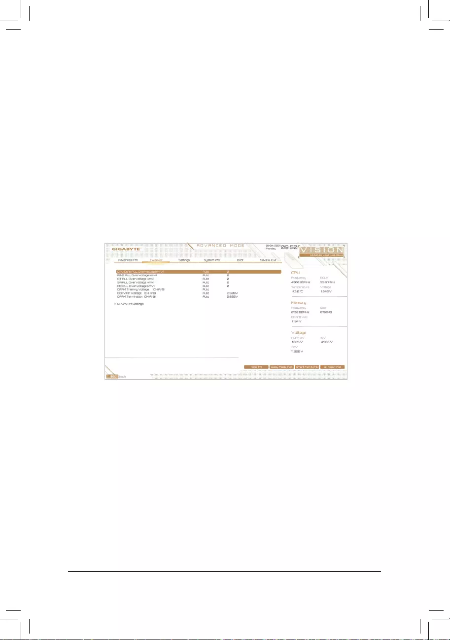
— 52 —
Advanced Voltage Settings
ThissubmenuallowsyoutocongureLoad-LineCalibrationlevel,over-voltageprotectionlevel,andover-
current protection level.
SPD Info
Displays information on the installed memory.
Memory Channels Timings
d Channels Standard Timing Control, Channels Advanced Timing Control, Channels
Misc Timing Control
These sections provide memory timing settings. Note: Your system may become unstable or fail to boot
after you make changes on the memory timings. If this occurs, please reset the board to default values by
loadingoptimizeddefaultsorclearingtheCMOSvalues.
& Vcore Volatge Mode/CPU Vcore/Dynamic Vcore(DVID)/BCLK Adaptive Voltage/CPU
Graphics Voltage (VAXG)/DRAM Voltage (CH A/B)/CPU VCCIO/CPU VCCIO2/CPU System
Agent Voltage/VCC Substained/VCCPLL OC/VCCVTT/ VCC STG/ VCC18 PCH/VCC1V8P
These items allow you to adjust the CPU Vcore and memory voltages.
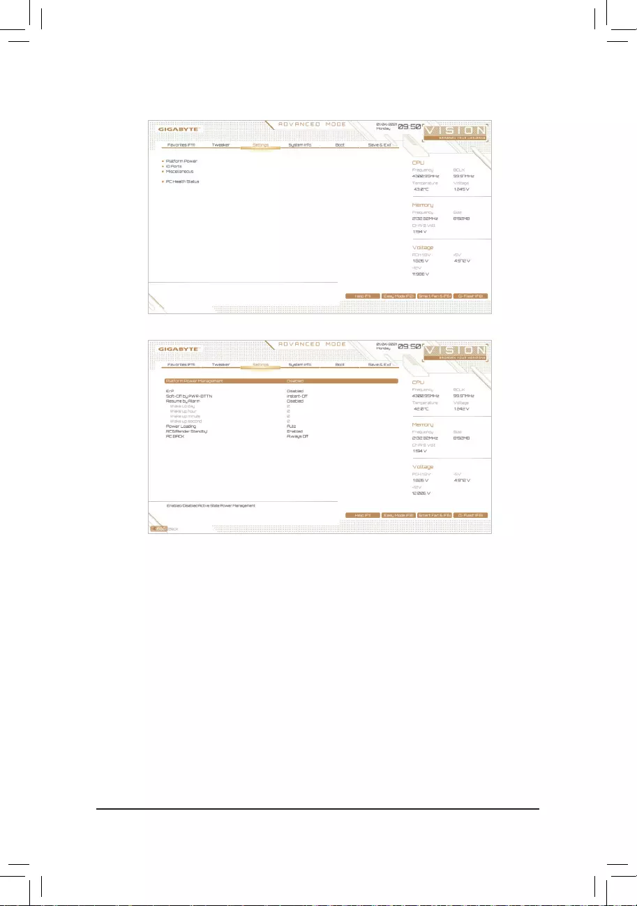
— 53 —
2-6 Settings
&Platform Power Management
Enables or disables the Active State Power Management function (ASPM). (Default: Disabled)
&PEG ASPM
Allowsyouto conguretheASPM modefor thedevice connectedto theCPUPEG bus.Thisitem is
congurableonlywhenPlatform Power Management is set to Enabled. (Default: Disabled)
&PCH ASPM
AllowsyoutoconguretheASPMmodeforthedeviceconnectedtoChipset’sPCIExpressbus.Thisitem
iscongurableonlywhenPlatform Power Management is set to Enabled. (Default: Disabled)
&DMI ASPM
AllowsyoutoconguretheASPMmodeforbothCPUsideandChipsetsideoftheDMIlink.Thisitemis
congurableonlywhenPlatform Power Management is set to Enabled. (Default: Disabled)
&ErP
Determines whether to let the system consume least power in S5 (shutdown) state. (Default: Disabled)
Note: When this item is set to Enabled,theResumebyAlarmfunctionbecomesunavailable.
Platform Power

— 54 —
&Soft-Off by PWR-BTTN
ConguresthewaytoturnoffthecomputerinMS-DOSmodeusingthepowerbutton.
Instant-Off Press the power button and then the system will be turned off instantly. (Default)
Delay 4 Sec. Press and hold the power button for 4 seconds to turn off the system. If the power
button is pressed for less than 4 seconds, the system will enter suspend mode.
&Resume by Alarm
Determines whether to power on the system at a desired time. (Default: Disabled)
If enabled, set the date and time as following:
Wakeupday:Turnonthesystemataspecictimeoneachdayoronaspecicdayinamonth.
Wakeuphour/minute/second:Setthetimeatwhichthesystemwillbepoweredonautomatically.
Note: When using this function, avoid inadequate shutdown from the operating system or removal of the
AC power, or the settings may not be effective.
&Power Loading
Enables or disables dummy load. When the power supply is at low load, a self-protection will activate causing
it to shutdown or fail. If this occurs, please set to Enabled. AutoletstheBIOSautomaticallycongurethis
setting. (Default: Auto)
&RC6(Render Standby)
Allows you to determine whether to let the onboard graphics enter standby mode to decrease power
consumption. (Default: Enabled)
&AC BACK
Determines the state of the system after the return of power from an AC power loss.
Memory The system returns to its last known awake state upon the return of the AC power.
Always On The system is turned on upon the return of the AC power.
Always Off The system stays off upon the return of the AC power. (Default)
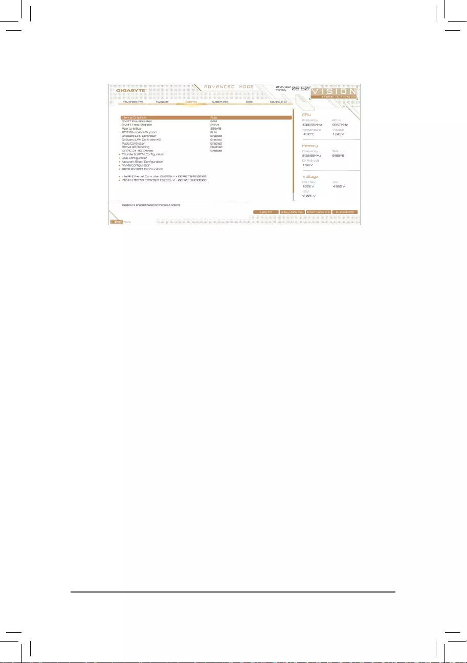
— 55 —
&Initial Display Output
SpeciestherstinitiationofthemonitordisplayfromtheinstalledPCIExpressgraphicscardortheonboard
graphics.
IGFX(Note) Setstheonboardgraphicsastherstdisplay.
PCIe1Slot SetsthegraphicscardonthePCIEX16slotastherstdisplay.(Default)
PCIe2Slot SetsthegraphicscardonthePCIEX8slotastherstdisplay.
PCIe3Slot SetsthegraphicscardonthePCIEX4slotastherstdisplay.
ThisitemiscongurableonlywhenCSM SupportissettoEnabled.
&Internal Graphics
Enablesordisablestheonboardgraphicsfunction.(Default:Auto)
&DVMT Pre-Allocated
Allowsyoutosettheonboardgraphicsmemorysize.(Default:64M)
&DVMT Total Gfx Mem
AllowsyoutoallocatetheDVMTmemorysizeoftheonboardgraphics.Optionsare:128M,256M,MAX.
(Default:256M)
&Aperture Size
Allowsyoutosetthemaximumamountofsystemmemorythatcanbeallocatedtothegraphicscard.
Optionsare:128MB,256MB,512MB,1024MB,and2048MB.(Default:256MB)
&PCIE Bifurcation Support
AllowsyoutodeterminehowthebandwidthofthePCIEX16slotisdivided.Options:Auto,PCIEx8/x8,
PCIEx8/x4/x4.(Default:Auto)
&OnBoard LAN Controller/OnBoard LAN Controller#2
EnablesordisablestheonboardLANfunction.(Default:Enabled)
Ifyouwishtoinstalla3rdpartyadd-innetworkcardinsteadofusingtheonboardLAN,setthisitemto
Disabled.
&Audio Controller
Enablesordisablestheonboardaudiofunction.(Default:Enabled)
Ifyouwishtoinstalla3rdpartyadd-inaudiocardinsteadofusingtheonboardaudio,setthisitemto
Disabled.
IO Ports
(Note) ThisitemispresentonlywhenyouinstallaCPUthatsupportsthisfeature.

— 56 —
&Above 4G Decoding
Enables or disables 64-bit capable devices to be decoded in above 4 GB address space (only if your system
supports 64-bit PCI decoding). Set to Enabled if more than one advanced graphics card are installed and
their drivers are not able to be launched when entering the operating system (because of the limited 4 GB
memory address space). (Default: Disabled)
&IOAPIC 24-119 Entries
Enables or disables this function. (Default: Enabled)
Thunderbolt(TM)Conguration
This sub-menu provides Intel® Thunderbolt™relatedinformationandcongurationoptions.
USBConguration
&Legacy USB Support
AllowsUSBkeyboard/mousetobeusedinMS-DOS.(Default:Enabled)
&XHCI Hand-off
Determines whether to enable XHCI Hand-off feature for an operating system without XHCI Hand-off
support. (Default: Enabled)
&USB Mass Storage Driver Support
Enables or disables support for USB storage devices. (Default: Enabled)
&Mass Storage Devices
Displays a list of connected USB mass storage devices. This item appears only when a USB storage device
is installed.
NetworkStackConguration
&Network Stack
Disables or enables booting from the network to install a GPT format OS, such as installing the OS from
the Windows Deployment Services server. (Default: Disabled)
&IPv4 PXE Support
EnablesordisablesIPv4PXESupport.ThisitemiscongurableonlywhenNetwork Stack is enabled.
&IPv4 HTTP Support
EnablesordisablesHTTPbootsupportforIPv4.ThisitemiscongurableonlywhenNetwork Stack is
enabled.
&IPv6 PXE Support
EnablesordisablesIPv6PXESupport.ThisitemiscongurableonlywhenNetwork Stack is enabled.
&IPv6 HTTP Support
EnablesordisablesHTTPbootsupportforIPv6.ThisitemiscongurableonlywhenNetwork Stack is
enabled.
&PXE boot wait time
Allowsyoutocongurehowlongtowaitbeforeyoucanpress<Esc>toabortthePXEboot.Thisitemis
congurableonlywhenNetwork Stack is enabled. (Default: 0)
&Media detect count
Allowsyoutosetthenumberoftimestocheckthepresenceofmedia.Thisitemiscongurableonlywhen
Network Stack is enabled. (Default: 1)

— 57 —
NVMeConguration
Displays information on your M.2 NVME PCIe SSD if installed.
SATAAndRSTConguration
&SATA Controller(s)
Enables or disables the integrated SATA controllers. (Default: Enabled)
&SATA Mode Selection
EnablesordisablesRAIDfortheSATAcontrollersintegratedintheChipsetorcongurestheSATAcontrollers
to AHCI mode.
IntelRSTPremiumWithIntelOptaneSystemAcceleration EnablesRAIDfortheSATAcontroller.
AHCI CongurestheSATAcontrollerstoAHCImode.AdvancedHostControllerInterface
(AHCI)isaninterfacespecicationthatallowsthestoragedrivertoenableadvanced
Serial ATA features such as Native Command Queuing and hot plug. (Default)
&Aggressive LPM Support
Enables or disables the power saving feature, ALPM (Aggressive Link Power Management), for the Chipset
SATA controllers. (Default: Disabled)
&Port 0/1/2/3/4/5
Enables or disables each SATA port. (Default: Enabled)
&SATA Port 0/1/2/3/4/5 DevSlp
Allows you to determine whether to let the connected SATA device go into sleep mode. (Default: Disabled)
&Hot plug
Enables or disable the hot plug capability for each SATA port. (Default: Disabled)
&ConguredaseSATA
Enables or disables support for external SATA devices.
Intel(R) Ethernet Controller
Thissub-menuprovidesinformationonLANcongurationandrelatedcongurationoptions.
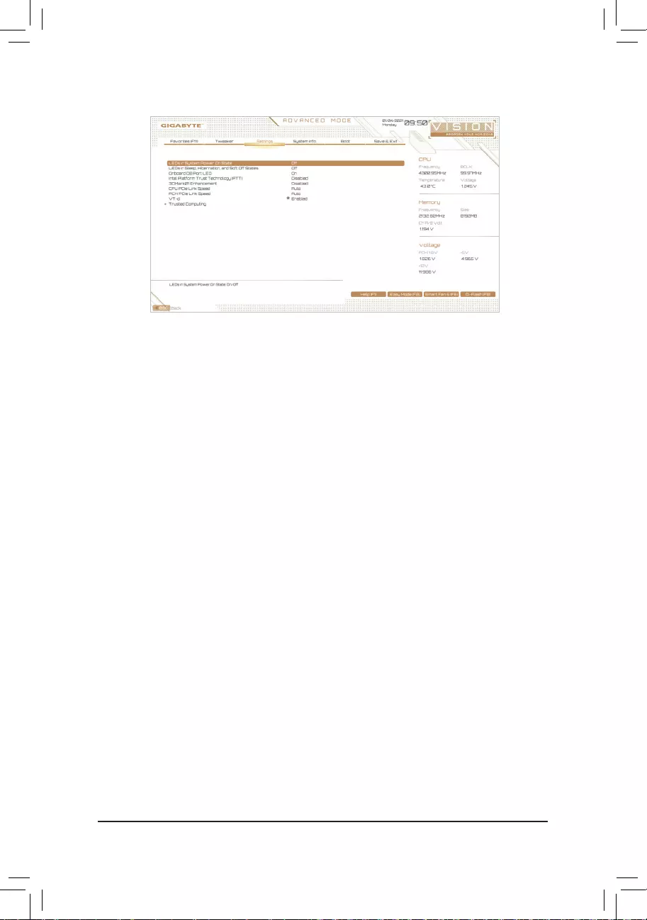
— 58 —
&LEDs in System Power On State
Allows you to enable or disable motherboard LED lighting when the system is on.
Off Disables the selected lighting mode when the system is on.
On Enables the selected lighting mode when the system is on. (Default)
&LEDs in Sleep, Hibernation, and Soft Off States
AllowsyoutosetthelightingmodeofthemotherboardLEDsinsystemS3/S4/S5state.
ThisitemiscongurablewhenLEDs in System Power On State is set to On.
Off DisablestheselectedlightingmodewhenthesystementersS3/S4/S5state.(Default)
On EnablestheselectedlightingmodewhenthesystementersS3/S4/S5state.
&Onboard DB Port LED
Allows you to enable or disable the LED lighting of the motherboard debug LEDs when the system is on.
(Default: On)
&Intel Platform Trust Technology (PTT)
Enables or disables Intel® PTT Technology. (Default: Disabled)
&3DMark01 Enhancement
Allows you to determine whether to enhance some legacy benchmark performance. (Default: Disabled)
&CPU PCIe Link Speed
Allows you to set the operation mode of the CPU-controlled PCI Express slots to Gen 1, Gen 2, Gen 3, or
Gen 4 (Note).Actualoperationmodeissubjecttothehardwarespecicationofeachslot.Auto lets the BIOS
automaticallycongurethissetting.(Default:Auto)
&PCH PCIe Link Speed
Allows you to set the operation mode of the Chipset-controlled PCI Express slots to Gen 1, Gen 2, or
Gen3.Actualoperationmodeissubjecttothehardwarespecicationofeachslot.Auto lets the BIOS
automaticallycongurethissetting.(Default:Auto)
&VT-d
Enables or disables Intel®VirtualizationTechnologyforDirectedI/O.(Default:Enabled)
Trusted Computing
Enables or disables Trusted Platform Module (TPM).
Miscellaneous
(Note) This item is present only when you install a CPU that supports this feature.

— 59 —
&Reset Case Open Status
Disabled Keeps or clears the record of previous chassis intrusion status. (Default)
Enabled Clears the record of previous chassis intrusion status and the Case Openeldwill
show «No» at next boot.
&Case Open
Displays the detection status of the chassis intrusion detection device attached to the motherboard CI
header.Ifthesystemchassiscoverisremoved,thiseldwillshow»Yes»,otherwiseitwillshow«No».To
clear the chassis intrusion status record, set Reset Case Open Status to Enabled, save the settings to
the CMOS, and then restart your system.
&CPU Vcore/CPU VCCSA/CPU VCCIO/DDRVtt A/B/DRAM Channel A/B Voltage/DDRVpp
A/B/+3.3V/+5V/PCH 1.8V/+12V/CPU VAXG
Displays the current system voltages.
PC Health Status
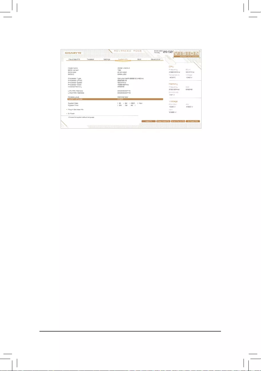
— 60 —
2-7 System Info.
This section provides information on your motherboard model and BIOS version. You can also select the default
language used by the BIOS and manually set the system time.
&Access Level
Displays the current access level depending on the type of password protection used. (If no password is
set, the default will display as Administrator.) The Administrator level allows you to make changes to all
BIOS settings; the User level only allows you to make changes to certain BIOS settings but not all.
&System Language
Selects the default language used by the BIOS.
&System Date
Sets the system date. The date format is week (read-only), month, date, and year. Use <Enter> to switch
betweentheMonth,Date,andYeareldsandusethe<PageUp>or<PageDown>keytosetthedesired
value.
&System Time
Sets the system time. The time format is hour, minute, and second. For example, 1 p.m. is 13:00:00. Use
<Enter>toswitchbetweentheHour,Minute,andSecondeldsandusethe<PageUp>or<PageDown>
key to set the desired value.
Plug in Devices Info
Displays information on your PCI Express and M.2 devices if installed.
Q-Flash
AllowsyoutoaccesstheQ-FlashutilitytoupdatetheBIOSorbackupthecurrentBIOSconguration.
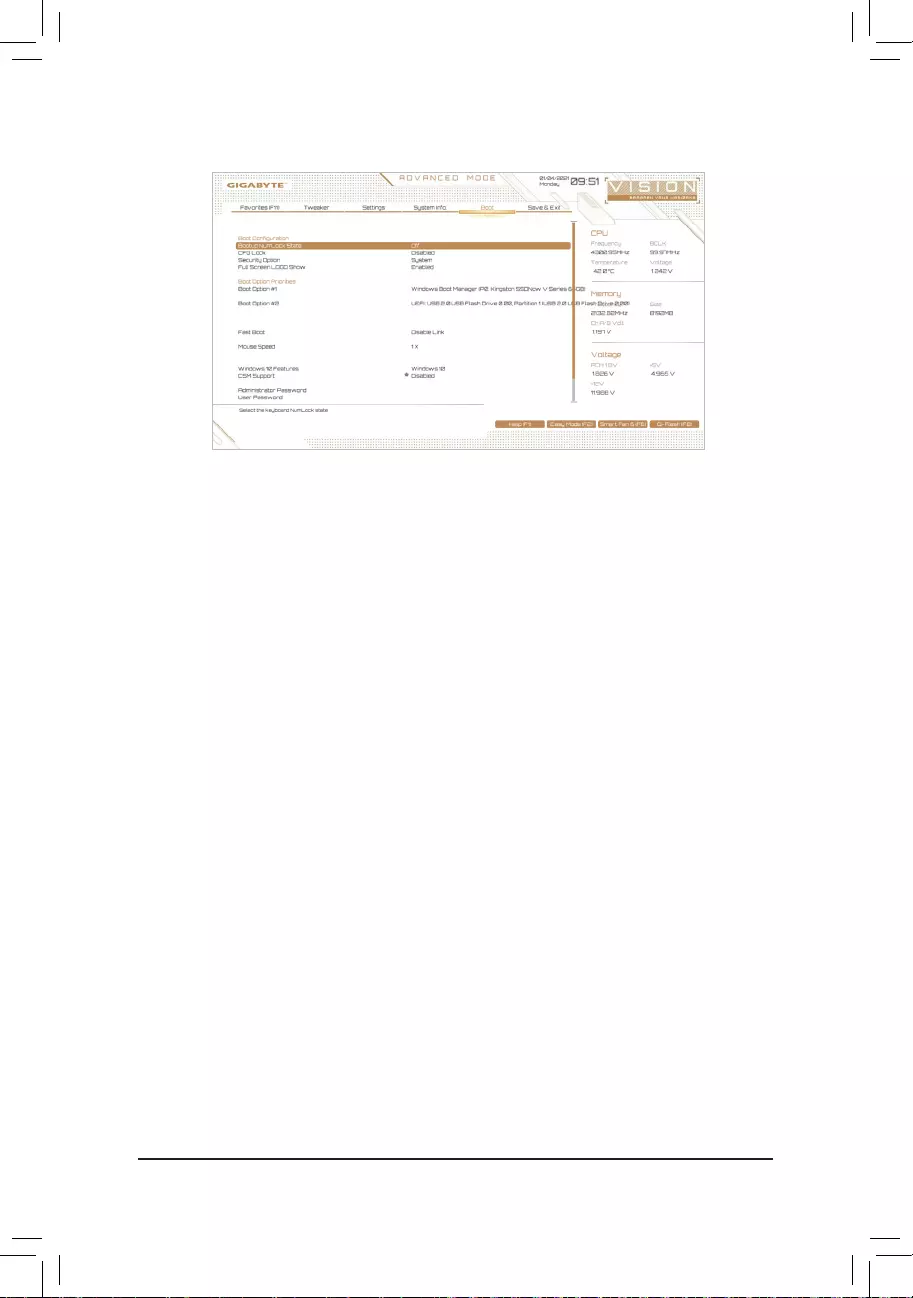
— 61 —
2-8 Boot
&Bootup NumLock State
Enables or disables Numlock feature on the numeric keypad of the keyboard after the POST. (Default: On)
&CFG Lock
EnablesordisablestheMSR0xE2function.(Default:Disabled)
&Security Option
Specieswhetherapasswordisrequiredeverytimethesystemboots,oronlywhenyouenterBIOSSetup.
Afterconguringthisitem,setthepassword(s)undertheAdministrator Password/User Password item.
Setup A password is only required for entering the BIOS Setup program.
System A password is required for booting the system and for entering the BIOS Setup program.
(Default)
&Full Screen LOGO Show
Allows you to determine whether to display the GIGABYTE Logo at system startup. Disabled skips the
GIGABYTE Logo when the system starts up. (Default: Enabled)
&Boot Option Priorities
Speciestheoverallbootorderfromtheavailabledevices.RemovablestoragedevicesthatsupportGPT
formatwillbeprexedwith«UEFI:»stringonthebootdevicelist.Tobootfromanoperatingsystemthat
supportsGPTpartitioning,selectthedeviceprexedwith»UEFI:»string.
Or if you want to install an operating system that supports GPT partitioning such as Windows 10 64-bit,
selecttheopticaldrivethatcontainstheWindows1064-bitinstallationdiscandisprexedwith«UEFI:»
string.
&Fast Boot
Enables or disables Fast Boot to shorten the OS boot process. Ultra Fast provides the fastest bootup
speed. (Default: Disable Link)
&SATA Support
Last Boot SATA Devices Only Except for the previous boot drive, all SATA devices are disabled
before the OS boot process completes. (Default)
All SATA Devices All SATA devices are functional in the operating system and during the POST.
ThisitemiscongurableonlywhenFast Boot is set to Enabled or Ultra Fast.

— 62 —
&VGA Support
Allows you to select which type of operating system to boot.
Auto EnableslegacyoptionROMonly.
EFIDriver EnablesEFIoptionROM.(Default)
ThisitemiscongurableonlywhenFast Boot is set to Enabled or Ultra Fast.
&USB Support
Disable Link All USB devices are disabled before the OS boot process completes.
Full Initial All USB devices are functional in the operating system and during the POST.
(Default)
Partial Initial Part of the USB devices are disabled before the OS boot process completes.
ThisitemiscongurableonlywhenFast Boot is set to Enabled or Ultra Fast. This function is disabled
when Fast Boot is set to Ultra Fast.
&NetWork Stack Driver Support
Disable Link Disables booting from the network. (Default)
Enabled Enables booting from the network.
ThisitemiscongurableonlywhenFast Boot is set to Enabled or Ultra Fast.
&Next Boot After AC Power Loss
Normal Boot Enables normal bootup upon the return of the AC power. (Default)
Fast Boot Keeps the Fast Boot settings upon the return of the AC power.
ThisitemiscongurableonlywhenFast Boot is set to Enabled or Ultra Fast.
&Mouse Speed
Allows you to set the mouse cursor movement speed. (Default: 1 X)
&Windows 10 Features
Allows you to select the operating system to be installed. (Default: Windows 10)
&CSM Support
Enables or disables UEFI CSM (Compatibility Support Module) to support a legacy PC boot process.
Disabled Disables UEFI CSM and supports UEFI BIOS boot process only. (Default)
Enabled Enables UEFI CSM.
&LAN PXE Boot Option ROM
AllowsyoutoselectwhethertoenablethelegacyoptionROMfortheLANcontroller.(Default:Disabled)
ThisitemiscongurableonlywhenCSM Support is set to Enabled.
&Storage Boot Option Control
AllowsyoutoselectwhethertoenabletheUEFIorlegacyoptionROMforthestoragedevicecontroller.
Donotlaunch DisablesoptionROM.
UEFI EnablesUEFIoptionROMonly.
Legacy EnableslegacyoptionROMonly.(Default)
ThisitemiscongurableonlywhenCSM Support is set to Enabled.

— 63 —
&Other PCI devices
AllowsyoutoselectwhethertoenabletheUEFIorLegacyoptionROMforthePCIdevicecontrollerother
than the LAN, storage device, and graphics controllers.
Donotlaunch DisablesoptionROM.
UEFI EnablesUEFIoptionROMonly.(Default)
Legacy EnableslegacyoptionROMonly.
ThisitemiscongurableonlywhenCSM Support is set to Enabled.
&Administrator Password
Allowsyoutocongureanadministratorpassword.Press<Enter>onthisitem,typethepassword,and
thenpress<Enter>.Youwillberequestedtoconrmthepassword.Typethepasswordagainandpress
<Enter>. You must enter the administrator password (or user password) at system startup and when entering
BIOS Setup. Differing from the user password, the administrator password allows you to make changes to
all BIOS settings.
&User Password
Allowsyoutocongureauserpassword.Press<Enter>onthisitem,typethepassword,andthenpress
<Enter>.Youwillberequestedtoconrmthepassword.Typethepasswordagainandpress<Enter>.
You must enter the administrator password (or user password) at system startup and when entering BIOS
Setup. However, the user password only allows you to make changes to certain BIOS settings but not all.
To cancel the password, press <Enter> on the password item and when requested for the password, enter
thecorrectonerst.Whenpromptedforanewpassword,press<Enter>withoutenteringanypassword.
Press<Enter>againwhenpromptedtoconrm.
NOTE:BeforesettingtheUserPassword,besuretosettheAdministratorPasswordrst.
Secure Boot
AllowsyoutoenableordisableSecureBootandcongurerelatedsettings.Thisitemiscongurableonly
when CSM Support is set to Disabled.
&Preferred Operating Mode
Allows you to select whether to enter Easy mode or Advanced mode after entering BIOS Setup. Auto
enters the BIOS mode where it was last time. (Default: Auto)
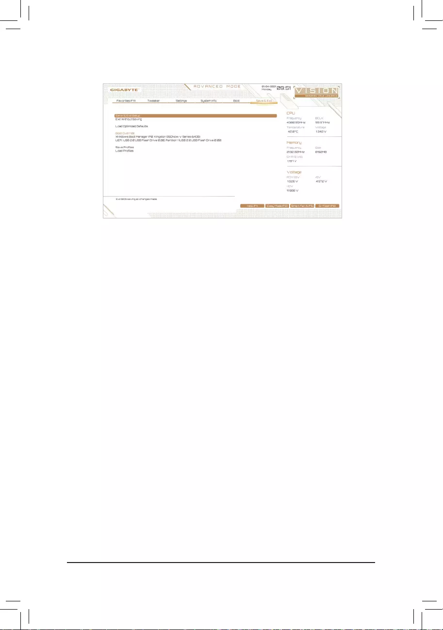
— 64 —
2-9 Save & Exit
&Save & Exit Setup
Press <Enter> on this item and select Yes. This saves the changes to the CMOS and exits the BIOS Setup
program. Select No or press <Esc> to return to the BIOS Setup Main Menu.
&Exit Without Saving
Press <Enter> on this item and select Yes. This exits the BIOS Setup without saving the changes made
in BIOS Setup to the CMOS. Select No or press <Esc> to return to the BIOS Setup Main Menu.
&Load Optimized Defaults
Press <Enter> on this item and select Yes to load the optimal BIOS default settings. The BIOS defaults
settingshelpthesystemtooperateinoptimumstate.AlwaysloadtheOptimizeddefaultsafterupdating
the BIOS or after clearing the CMOS values.
&Boot Override
Allows you to select a device to boot immediately. Press <Enter> on the device you select and select Yes
toconrm.Yoursystemwillrestartautomaticallyandbootfromthatdevice.
&SaveProles
ThisfunctionallowsyoutosavethecurrentBIOSsettingstoaprole.Youcancreateupto8prolesand
saveasSetupProle1~SetupProle8.Press<Enter>tocomplete.OryoucanselectSelect File in
HDD/FDD/USBtosavetheproletoyourstoragedevice.
&LoadProles
If your system becomes unstable and you have loaded the BIOS default settings, you can use this function
toloadtheBIOSsettingsfromaprolecreatedbefore,without thehasslesofreconguringtheBIOS
settings.Firstselecttheproleyouwishtoloadandthenpress<Enter>tocomplete.YoucanselectSelect
File in HDD/FDD/USBtoinputtheprolepreviouslycreatedfromyourstoragedeviceorloadtheprole
automatically created by the BIOS, such as reverting the BIOS settings to the last settings that worked
properly (last known good record).

— 65 —
Chapter3 ConguringaRAIDSet
To create a RAID set, follow the steps below:
A. Install SATA hard drive(s) or SSDs in your computer.
B. CongureSATAcontrollermodeinBIOSSetup.
C. CongureaRAIDarrayinRAIDBIOS.(Note 1)
D. InstalltheRAIDdriverandoperatingsystem.
Before you begin, please prepare the following items:
•At least two SATA hard drives or SSDs (Note 2) (to ensure optimal performance, it is recommended that you
use two hard drives with identical model and capacity). (Note 3)
•A Windows setup disc.
•Motherboard driver disc.
•A USB thumb drive.
RAID Levels
3-1 ConguringSATAControllers
A. Installing hard drives
Installtheharddrives/SSDsintheIntel® Chipset controlled connectors on the motherboard. Then connect
the power connectors from your power supply to the hard drives.
RAID 0 RAID 1 RAID 5 RAID 10
Minimum
Number of Hard
Drives
≥2 2≥3 4
Array Capacity
Number of hard
drives*Sizeofthe
smallest drive
Sizeofthesmallest
drive
(Number of hard
drives-1)*Sizeof
the smallest drive
(Number of hard
drives/2)*Sizeofthe
smallest drive
Fault Tolerance No Yes Yes Yes
(Note1) SkipthisstepifyoudonotwanttocreateRAIDarrayontheSATAcontroller.
(Note2) AnM.2PCIeSSDcannotbeusedtosetupaRAIDseteitherwithanM.2SATASSDoraSATAhard
drive.
(Note3)Referto»InternalConnectors»fortheinstallationnoticesfortheM.2andSATAconnectors.
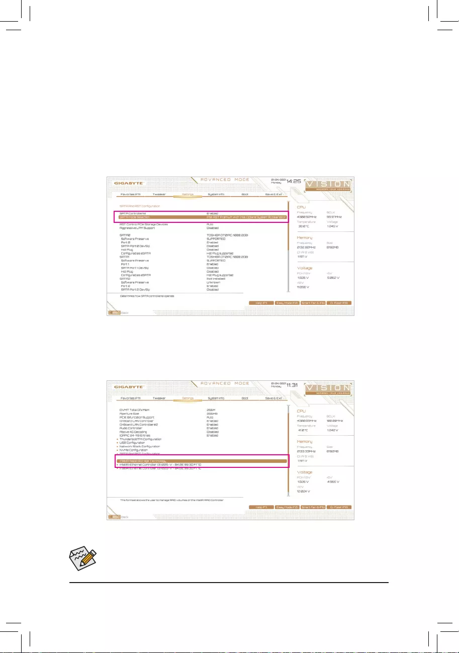
— 66 —
The BIOS Setup menus described in this section may differ from the exact settings for your motherboard.
The actual BIOS Setup menu options you will see shall depend on the motherboard you have and
the BIOS version.
B.ConguringSATAcontrollermodeinBIOSSetup
MakesuretoconguretheSATAcontrollermodecorrectlyinsystemBIOSSetup.
Step:
Turn on your computer and press <Delete> to enter BIOS Setup during the POST (Power-On Self-Test). Go
to SettingsIOPortsSATAAndRSTConguration, make sure SATA Controller(s) is enabled. To create
RAID,setSATA Mode Selection to Intel RST Premium With Intel Optane System Acceleration. Then save
the settings and restart your computer (Figure 1). Note: When using a PCIe SSD, make sure to set the RST
Control PCIe Storage Devices item under SettingsIOPortsSATAAnd RST Conguration to Manual.
Then depending the M.2 connector you use, set the corresponding PCIe Storage Dev on Port XX item to RST
Controlled. Finally, save the settings and exit BIOS Setup.
Figure 1
C.UEFIRAIDConguration
Step 1:
After the system reboot, enter BIOS Setup again. Then enter the SettingsIO PortsIntel(R) Rapid Storage
Technology sub-menu (Figure 2).
Figure 2
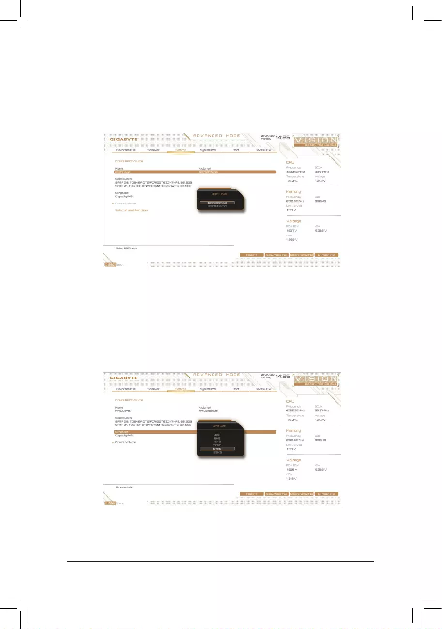
— 67 —
Step 2:
On the Intel(R) Rapid Storage Technology menu, press <Enter> on Create RAID Volume to enter the Create
RAID Volume screen. Enter a volume name with 1~16 letters (letters cannot be special characters) under the
Nameitemandpress<Enter>.Then,selectaRAIDlevel(Figure3).RAIDlevelssupportedincludeRAID0,
RAID1,RAID10,andRAID5(theselectionsavailabledependonthenumberoftheharddrivesbeinginstalled).
Next, use the down arrow key to move to Select Disks.
Figure 3
Step 3:
Under Select Disksitem,selecttheharddrivestobeincludedintheRAIDarray.Pressthe<Space>keyon
theharddrivestobeselected(selectedharddrivesaremarkedwith«X»).Thensetthestripeblocksize(Figure
4).Thestripeblocksizecanbesetfrom4KBto128KB.Onceyouhaveselectedthestripeblocksize,set
the volume capacity.
Figure 4
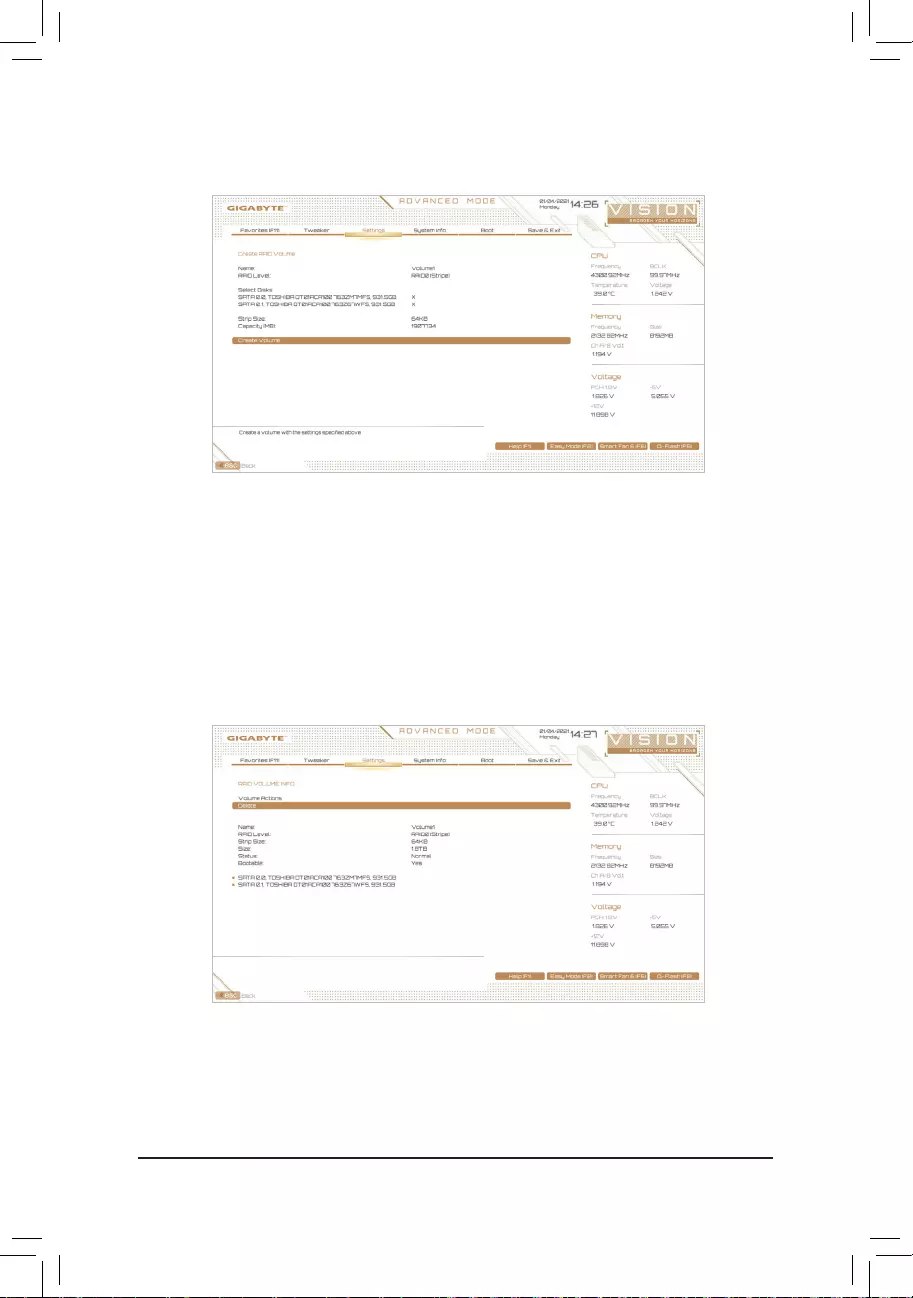
— 68 —
Step 4:
After setting the capacity, move to Create Volume and press <Enter> to begin. (Figure 5)
Figure 5
After completing, you’ll be brought back to the Intel(R) Rapid Storage Technology screen. Under RAID Volumes
youcanseethenewRAIDvolume.Toseemoredetailedinformation,press<Enter>onthevolumetocheckfor
informationonRAIDlevel,stripeblocksize,arrayname,andarraycapacity,etc.(Figure6)
Figure 6

— 69 —
Delete RAID Volume
TodeleteaRAIDarray,press<Enter>onthevolumetobedeletedontheIntel(R) Rapid Storage Technology
screen. After entering the RAID VOLUME INFO screen, press <Enter> on Delete to enter the Delete screen.
Press <Enter> on Yes (Figure 7).
Figure 7
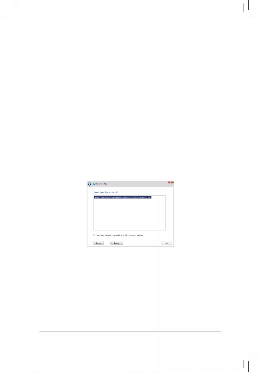
— 70 —
3-2 Installing the RAID Driver and Operating System
With the correct BIOS settings, you are ready to install the operating system.
AssomeoperatingsystemsalreadyincludeRAIDdriver,youdonotneedtoinstallseparateRAIDdriverduring
the Windows installation process. After the operating system is installed, we recommend that you install all
required drivers from the motherboard driver disc using «Xpress Install» to ensure system performance and
compatibility.IftheoperatingsystemtobeinstalledrequiresthatyouprovideadditionalRAIDdriverduringthe
OS installation process, please refer to the steps below:
Step 1:
Copy the IRST folder under Boot in the driver disc to your USB thumb drive.
Step 2:
Boot from the Windows setup disc and perform standard OS installation steps. When the screen requesting you
to load the driver appears, select Browse.
Step 3:
Insert the USB thumb drive and then browse to the location of the driver. The location of the driver is as follows:
IRSTf6py-x64
Step 4:
When a screen as shown in Figure 1 appears, select Intel(R) Chipset SATA/PCIe RST Premium Controller
and click Next to load the driver and continue the OS installation.
Figure 1
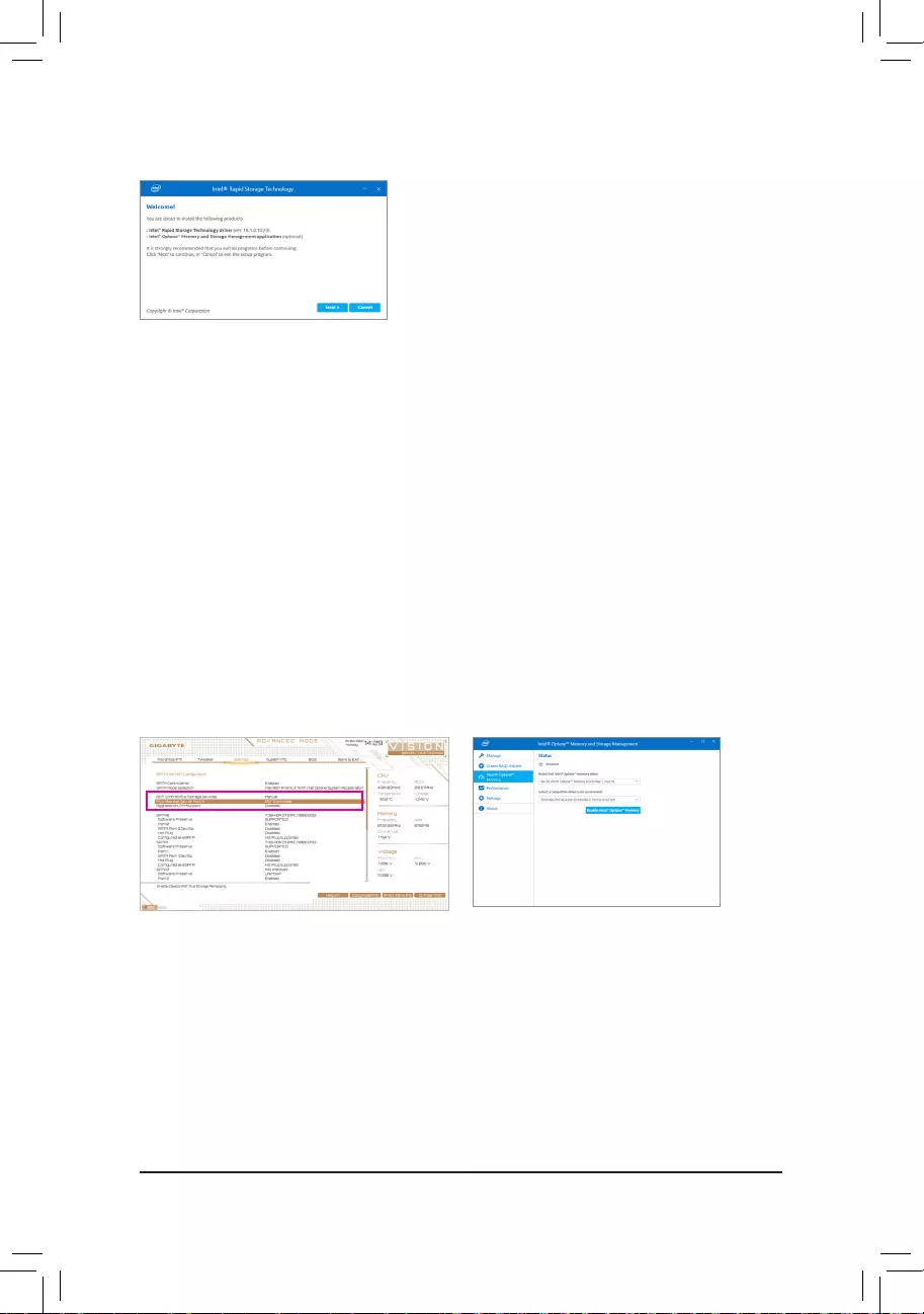
— 71 —
3-3 Installing Intel® Optane™ Memory and Storage Management
Step 1:
After entering the operating system, insert the motherboard driver
disc into your optical drive. On the Xpress Install screen, select
Intel® Optane™ Memory and Storage Management to install and
follow the on-screen instructions to complete the installation. When
completed, restart the system.
Step 2:
After you install the included motherboard drivers, make sure your
Internet connection works properly. The system will automatically
install the software from Intel®.Restartthesystemafterthedriver
is installed.
A. Enabling an Intel® Optane™ Memory
A-1. System Requirements
1. Intel® Optane™ memory
2. The Optane™ memory must have at least 16 GB capacity, and it must have equal or smaller capacity than
theharddrive/SSDtobeaccelerated.
3. The Optane™memorycannotbeusedtoaccelerateanexistingRAIDarray;theacceleratedharddrive/SSD
cannotbeincludedinaRAIDarray.
4. Theharddrive/SSDtobeacceleratedmustbeaSATAharddriveorM.2SATASSD.
5. Theharddrive/SSDtobeacceleratedcanbeasystemdriveordatadrive.ThesystemdrivemustbeGPTformatted
and have Windows 10 64-bit (or later version) installed on it. The data drive must also be GPT formatted.
6. The motherboard driver disc.
7. TheSATAcontrollermustsetinIntelRSTPremiumWithIntelOptaneSystemAccelerationmode.
Step 1:
Go to SettingsIOPortsSATAAndRSTConguration
and make sure RST Control PCIe Storage Devices
is set to Manual. Then depending on which M.2
connector you install the Optane™ memory in, set the
corresponding PCIe Storage Dev on Port XX item to
RST Controlled.
Step 2:
After re—entering the operating system, launch the
Intel® Optane™ Memory and Storage Management
application from the Start menu. If you install more
than one Optane™ memory, please select which one
you are going to use. Then select which drive to be
accelerated. Click Enable Intel® Optane™ Memory.
All data on the Optane™ memory will be erased. Make
sure you back up the data before continuing. Follow the
on-screen instructions to proceed. When completed,
restart the system.
A-2. Installation Guidelines
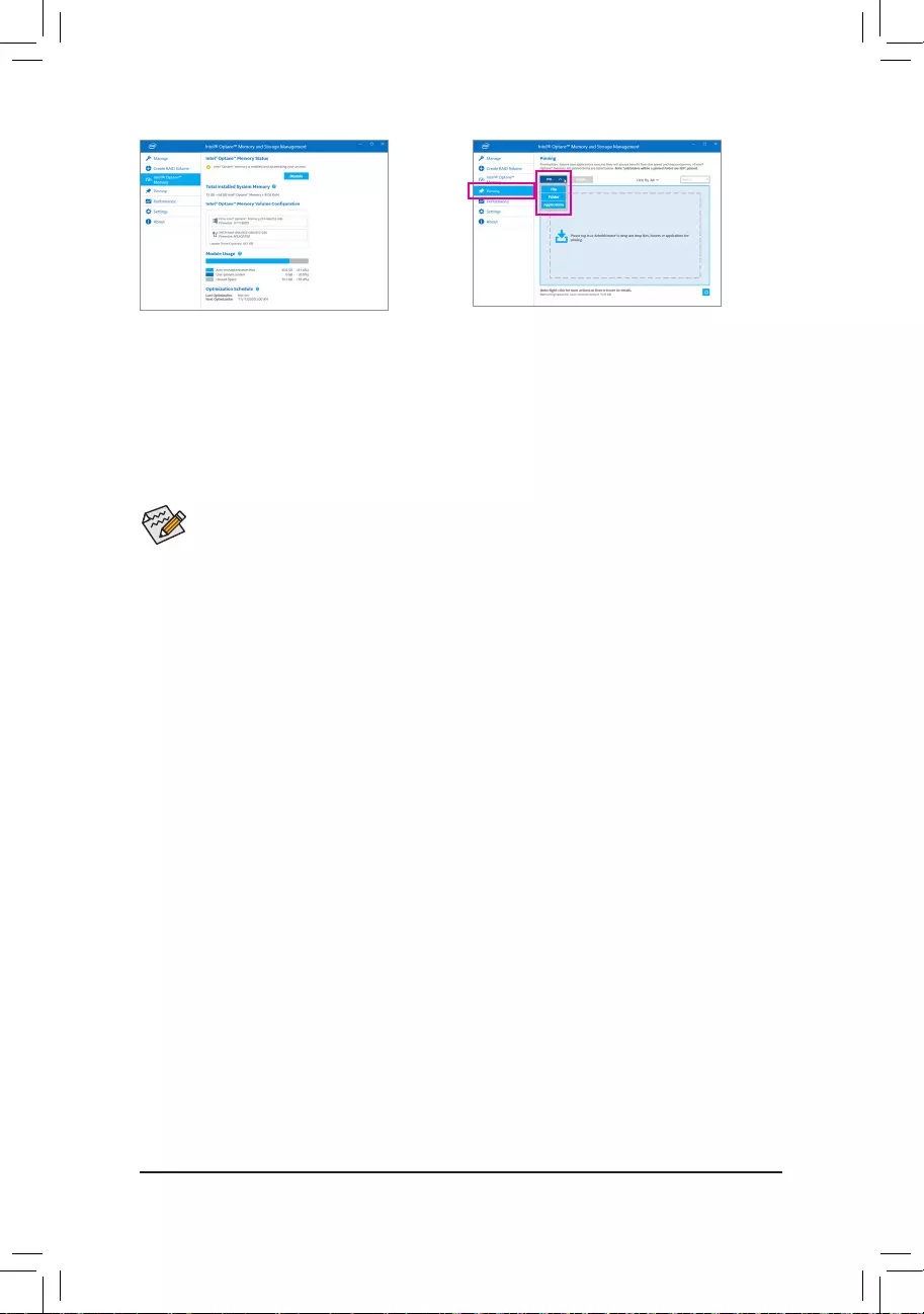
— 72 —
Step 3:
Launch the Intel® Optane™ Memory and Storage
Management application from the Start menu and
make sure the Intel® Optane™ Memory has been
enabled.
Step 4:
If you want to accelerate the system drive, you
can select specic folders, les, or applications to
accelerate using the Intel® Optane™ Memory Pinning
function. (The Optane™ memory used must have at
least 32 GB capacity.)
•An Optane™ memory cannot be used to accelerate an M.2 PCIe SSD.
•If more than one Optane™ memory is installed, you can select only one of them to accelerate your
SATA-based boot drive. The other(s) can only be used as data drive(s).
•Do not abruptly remove the Optane™ memory. Doing so will cause the operating system to stop
functioning correctly.
•Ifyouwanttochange/removetheOptane™ memory, you must disable it using the Intel® Optane™
Memory and Storage Managementapplicationrst.
•After enabling the Optane™ memory, the related BIOS settings will remain even after a BIOS update.
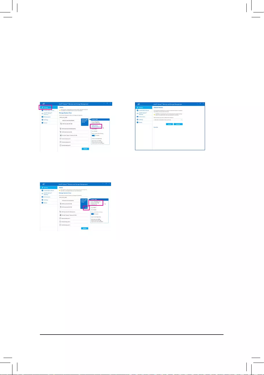
— 73 —
B. Rebuilding an Array
Rebuildingistheprocessofrestoringdatatoaharddrivefromotherdrivesinthearray.Rebuildingappliesonly
tofault-tolerantarrayssuchasRAID1,RAID5orRAID10arrays.Theproceduresbelowassumeanewdrive
isaddedtoreplaceafaileddrivetorebuildaRAID1array.(Note:Thenewdrivemusthaveequalorgreater
capacity than the old one.)
Turnoffyourcomputerandreplacethefailedharddrivewithanewone.Restartyourcomputer.
While in the operating system, launch the Intel® Optane™ Memory and Storage Management utility from the
Start menu.
Step 1:
Go to the Manage menu and click Rebuild to another
disk in Manage Volume.
The Status item on the right of the screen displays the
rebuildprogress.AftertheRAID1volumerebuilding,
the Status will display as Normal.
Step 2:
Selecta new drive to rebuildthe RAID and click
Rebuild.

— 74 —
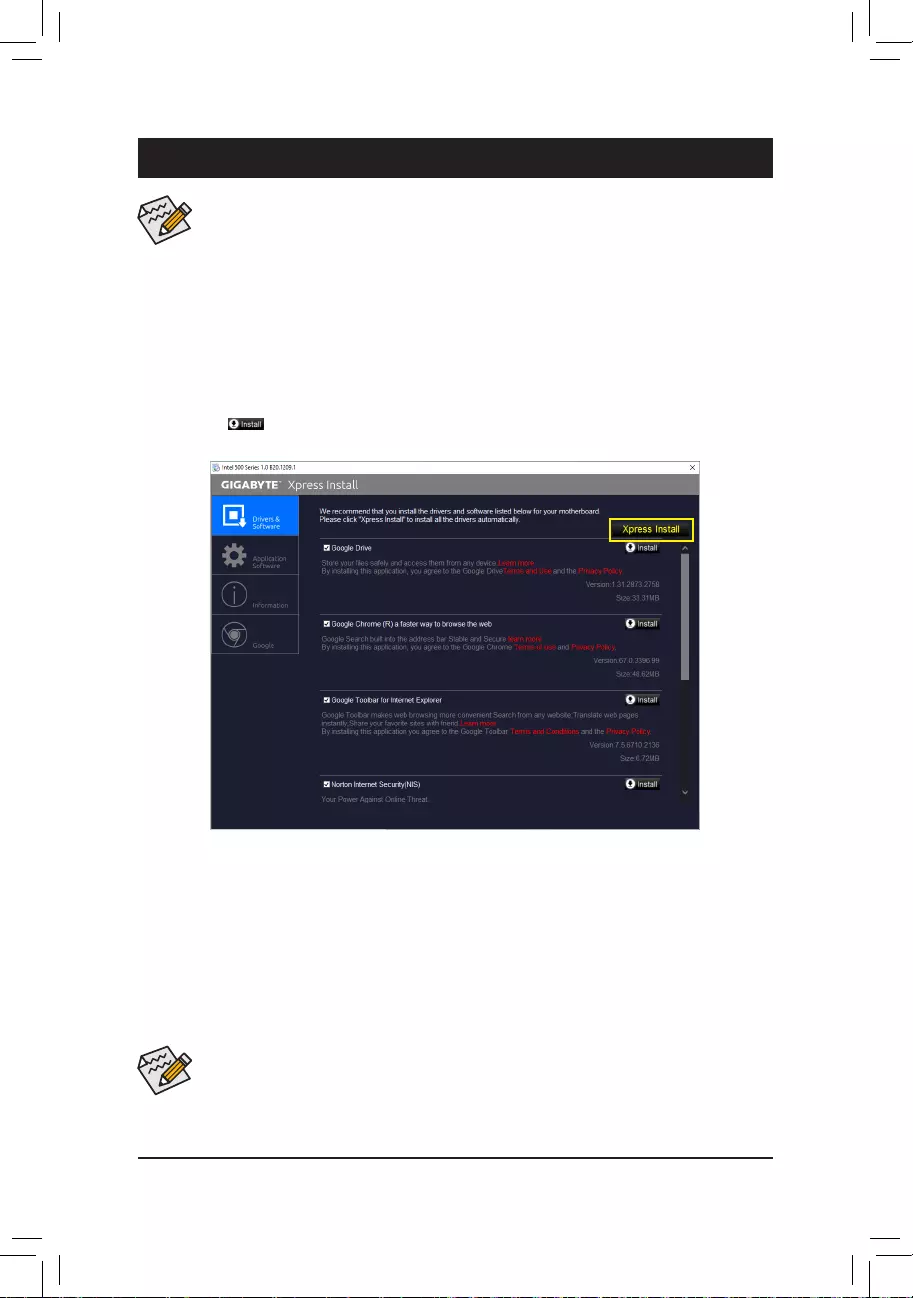
— 75 —
4-1 Drivers & Software
Chapter 4 Drivers Installation
•Beforeinstallingthedrivers,rstinstalltheoperatingsystem.
•After installing the operating system, insert the motherboard driver disk into your optical drive.
Click on the message «Tap to choose what happens with this disc» on the top-right corner of
the screenandselect «RunRun.exe.» (Or go to My Computer, double-click the optical drive
andexecutetheRun.exeprogram.)
•Please ignore the popup dialog box(es) (e.g. the Found New Hardware Wizard) displayed
when «Xpress Install» is installing the drivers. Failure to do so may affect the driver installation.
•Some device drivers will restart your system automatically during the driver installation. After the
system restart, «Xpress Install» will continue to install other drivers.
«Xpress Install» will automatically scan your system and then list all of the drivers that are recommended to
install. You can click the Xpress Install button and «Xpress Install» will install all of the selected drivers. Or
click the arrow icon to individually install the drivers you need.
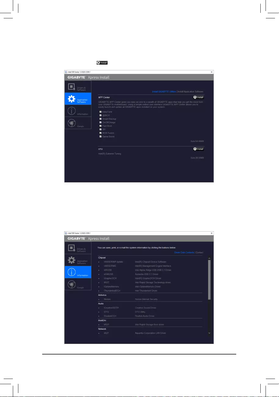
— 76 —
4-3 Information
This page provides detailed information on the drivers on the driver disk. The Contact page provides
contactinformationoftheGIGABYTETaiwanheadquarter.YoucanclicktheURLonthispagetolinktothe
GIGABYTEwebsitetocheckmoreinformationontheGIGABYTEheadquarterorworldwidebranchofces.
4-2 Application Software
This page displays the apps that GIGABYTE develops and some free software. You can select the apps
you want and click the Install icon to begin the installation.

— 77 —
Chapter 5 Unique Features
BecauseBIOSashingispotentiallyrisky,pleasedoitwithcaution.InadequateBIOSashingmay
result in system malfunction.
5-1-1 Updating the BIOS with the Q-Flash Utility
A. Before You Begin
1. FromGIGABYTE’swebsite,downloadthelatestcompressedBIOSupdatelethatmatchesyourmotherboard
model.
2. ExtracttheleandsavethenewBIOSle(e.g.Z590VISIOND.F1)toyourUSBashdrive,orharddrive.
Note:TheUSBashdriveorharddrivemustuseFAT32/16/12lesystem.
3. Restartthesystem.DuringthePOST,pressthe<End>keytoenterQ-Flash.Note:YoucanaccessQ-Flash
by either pressing the <End> key during the POST or click the Q-Flash icon (or press the <F8> key) in BIOS
Setup.However,iftheBIOSupdateleissavedtoaharddriveinRAID/AHCImodeoraharddriveattached
to an independent SATA controller, use the <End> key during the POST to access Q-Flash.
5-1 BIOS Update Utilities
GIGABYTE motherboards provide two unique BIOS update tools, Q-Flash™ and @BIOS™. GIGABYTE Q-Flash
and @BIOS are easy-to-use and allow you to update the BIOS without the need to enter MS-DOS mode.
Additionally, this motherboard supports Q-Flash Plus, providing multiple protection for the safety and stability
of your computer.
What is Q-Flash Plus?
Q-Flash Plus allows you to update the BIOS when your system is off (S5 shutdown state). Save the latest BIOS
onaUSBthumbdriveandplugitintothededicatedport,andthenyoucannowashtheBIOSautomatically
by simply pressing the Q-Flash Plus button.
What is Q-Flash™?
With Q-Flash you can update the system BIOS without having to enter operating systems like MS-DOS or
Windowrst.EmbeddedintheBIOS,theQ-Flashtoolfreesyoufromthehasslesofgoingthroughcomplicated
BIOSashingprocess.
What is @BIOS™?
@BIOS allows you to update the system BIOS while in the Windows environment. @BIOS will download the
latestBIOSlefromthenearest@BIOSserversiteandupdatetheBIOS.
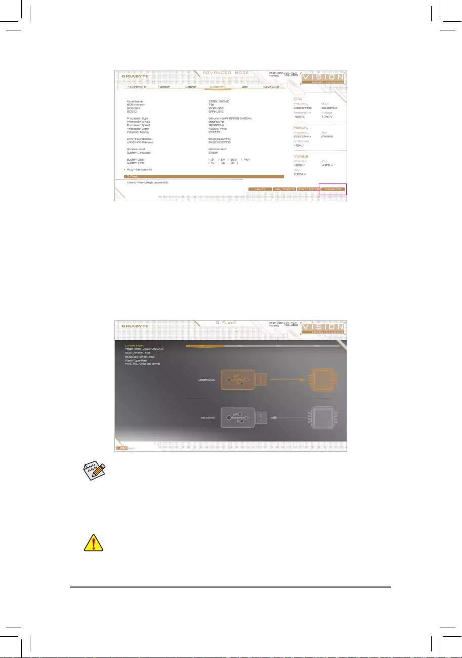
— 78 —
B. Updating the BIOS
In the main menu of Q-Flash, use the keyboard or mouse to select an item to execute. When updating the BIOS,
choosethelocationwheretheBIOSleissaved.Thefollowingprocedureassumesthatyouhavesavedthe
BIOSletoaUSBashdrive.
Step 1:
1. InserttheUSBashdrivecontainingtheBIOSleintothecomputer.InthemainscreenofQ-Flash,select
Update BIOS.
•The Save BIOSoptionallowsyoutosavethecurrentBIOSle.
•Q-FlashonlysupportsUSBashdriveorharddrivesusingFAT32/16/12lesystem.
•IftheBIOSupdateleissavedtoaharddriveinRAID/AHCImodeoraharddriveattached
to an independent SATA controller, use the <End> key during the POST to access Q-Flash.
2. SelecttheBIOSupdatele.
MakesuretheBIOSupdatelematchesyourmotherboardmodel.
Click Q-Flash (F8) or select the Q-Flash item on the System Info menu to access Q-Flash.
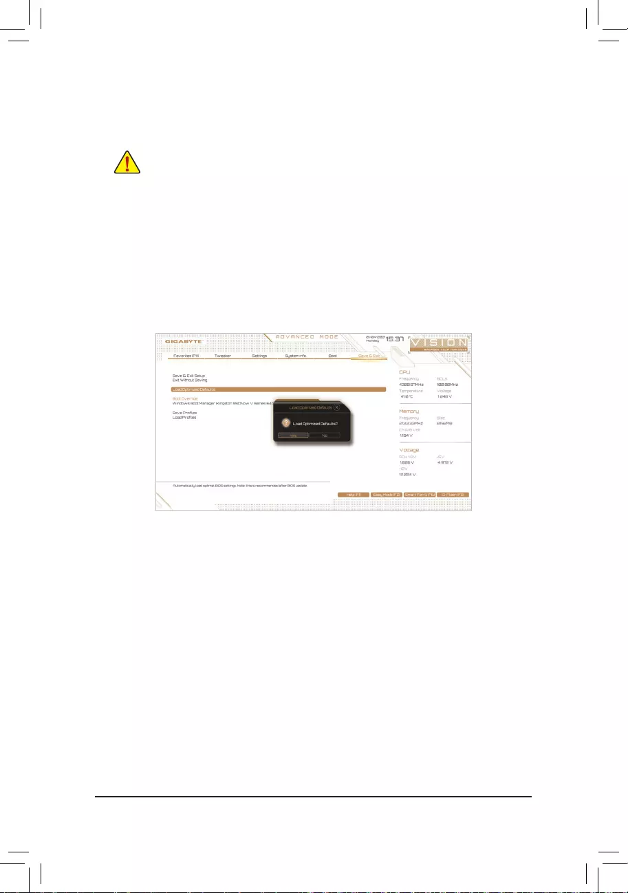
— 79 —
Step 2:
ThescreenwillshowthattheBIOSleisbeingreadfromyourUSBashdrive.PleaseselectFast or Intact to
begin the BIOS update. The screen will then display the update process.
Step 3:
The system will restart after the update process is complete.
•Do not turn off or restart the system when the system is reading/updating the BIOS.
•DonotremovetheUSBashdriveorharddrivewhenthesystemisupdatingtheBIOS.
Step 4:
During the POST, press <Delete> to enter BIOS Setup. Select Load Optimized Defaults on the Save & Exit
screen and press <Enter> to load BIOS defaults. System will re-detect all peripheral devices after a BIOS update,
so we recommend that you reload BIOS defaults.
Step 5:
Select Save & Exit Setup and press <Enter>. And then select Yes to save settings to CMOS and exit BIOS
Setup. The procedure is complete after the system restarts.
Select Yes to load BIOS defaults
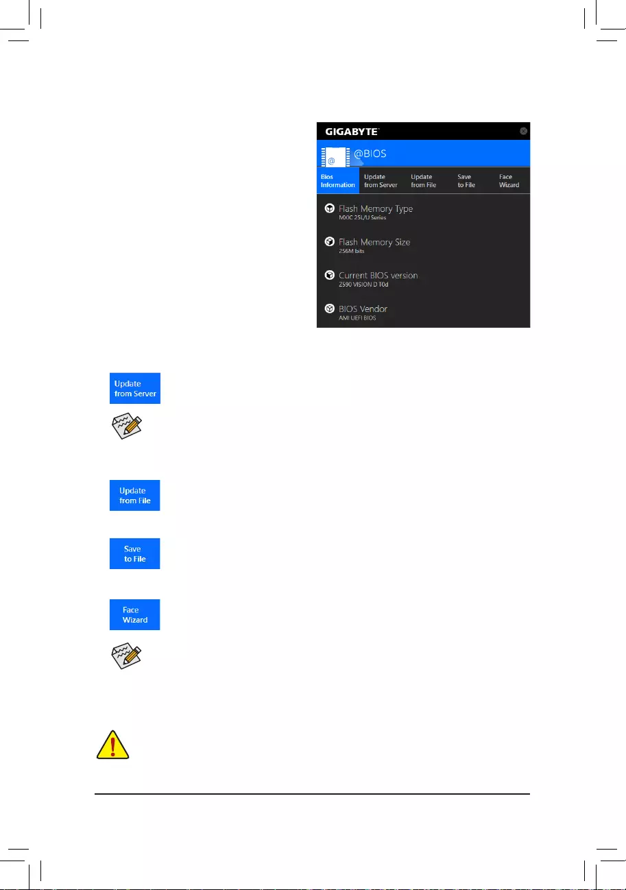
— 80 —
5-1-2 Updating the BIOS with the @BIOS Utility
A. Before You Begin
1. In Windows, close all applications andTSR
(Terminateand Stay Resident) programs.This
helps prevent unexpected failures when performing
a BIOS update.
2. If the BIOS is being updated via the Internet, ensure
the Internet connection is stable and do NOT
interrupt the Internet connection (for example, avoid
a power loss or switching off the Internet). Failure to
do so may result in a corrupted BIOS or a system
that is unable to start.
3. GIGABYTE product warranty does not cover any
BIOS damage or system failure resulting from an
inadequateBIOSashing.
B. Using @BIOS
•MakesurethattheBIOSletobeashedmatchesyourmotherboardmodel.UpdatingtheBIOS
withanincorrectBIOSlecouldcauseyoursystemnottoboot.
•Do not turn off the system or remove the power during the BIOS update process, or the BIOS may
corrupt and the system may not boot.
IftheBIOS updatele foryourmotherboard isnot presentonthe @BIOSserver site,please
manuallydownloadtheBIOSupdatelefromGIGABYTE’swebsiteandfollowtheinstructionsin
«Update the BIOS without Using the Internet Update Function» below.
Supported image formats include jpg, bmp, and gif.
C. After Updating the BIOS
RestartyoursystemafterupdatingtheBIOS.
1. Update the BIOS Using the Internet Update Function:
Click Update from Server, select the @BIOS server site closest to your location and
thendownloadtheBIOSlethatmatchesyourmotherboardmodel.Followtheon-screen
instructions to complete.
2. Update the BIOS without Using the Internet Update Function:
Click Update from File,thenselectthelocationwhereyousavetheBIOSupdateleobtained
from the Internet or through other source. Follow the on-screen instructions to complete.
3. Save the Current BIOS File:
Click Save to FiletosavethecurrentBIOSle.
4. Change the Boot-up Logo:
Click Upload new imageinFace-Wizardandyouwillbeabletochangetheboot-uplogo
withyourownpicture,creatingapersonalizedboot-upscreen.ClickBackup current image
to save the current boot-up logo.

— 81 —
5-1-3 Using Q-Flash Plus
A. Before You Begin
1. FromGIGABYTE’swebsite,downloadthelatestcompressedBIOSupdatelethatmatchesyourmotherboard
model.
2. UncompressthedownloadedBIOSle,saveittoyourUSBashdrive,andrenameittoGIGABYTE.bin.
Note:TheUSBashdrivemustusetheFAT32/16lesystemanditmustbeaUSB2.0ashdrive.
3. Connect the power cables to the 12V power connector (connect either one if there are two) and main power
connector.
4. PleaseturnonthepowersupplybeforeconnectingtheUSBashdrivetotheQ-FlashPlusportonthe
back panel.
B. Using Q-Flash Plus
PresstheQ-FlashPlusbuttonandthesystemwillautomaticallysearchandmatchtheBIOSleintheUSB
ashdriveontheQ-FlashPlusport.TheQFLEDandtheQ-FlashPlusbuttonontherearpanelwillashduring
theBIOSmatchingandashingprocess.Waitfor6-8minutesandtheLEDswillstopashingwhentheBIOS
ashingiscomplete.
•IfyouchoosetoupdatetheBIOSmanually,rstmakesurethatyoursystemisoff(S5shutdown
state).
•If your motherboard has a BIOS switch and a SB switch, reset them to their default settings.
(Default setting for the BIOS switch: Boot from the main BIOS; default setting for the SB switch:
Dual BIOS)
•On motherboards with DualBIOS™, the DualBIOS™ feature will continue to update the backup
BIOSafterthemainBIOShasbeenashedandthesystemrestarts.Aftercompletion,thesystem
will reboot again and boot from the main BIOS.
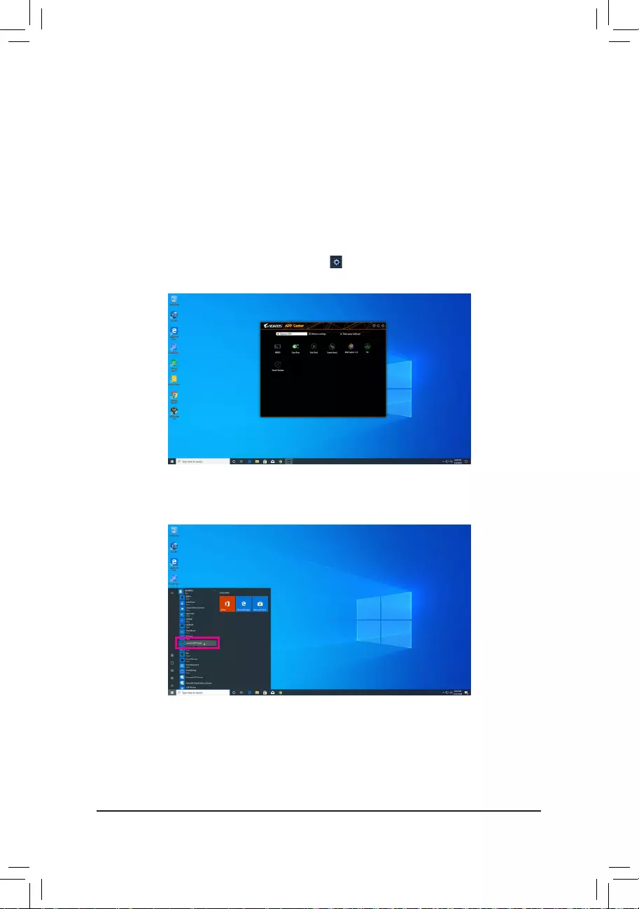
— 82 —
5-2 APP Center
GIGABYTE App Center gives you easy access to a wealth of GIGABYTE apps that help you get the most from
your GIGABYTE motherboard (Note). Using a simple, unied user interface, GIGABYTE App Center allows you
to easily launch all GIGABYTE apps installed on your system, check related updates online, and download the
apps, drivers, and BIOS.
Running the APP Center
Insert the motherboard driver disc. On the Autorun screen, go to Application SoftwareInstall GIGABYTE
Utilities to install GIGABYTE App Center and the selected apps. Restart your computer after the installation
is complete. In Desktop mode, click the App Center icon in the notication area to launch the App Center
utility (Figure 1). On the main menu, you can select an app to run or click LiveUpdate to update an app online.
If the App Center is closed, you can restart it by clicking Launch App Center on the Start menu (Figure 2).
Figure 2
Figure 1
(Note) Available applications in APP Center may differ by motherboard model. Supported functions of each
application may also vary depending on motherboard specications.
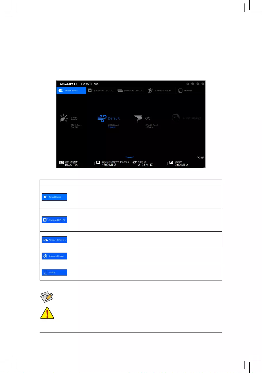
— 83 —
5-2-1 EasyTune
GIGABYTE’sEasyTuneisasimpleandeasy-to-useinterfacethatallowsuserstone-tunetheirsystemsettings
ordooverclock/overvoltageinWindowsenvironment.
The EasyTune Interface
Tabs Information
Tab Description
The Smart Boost tab provides you with different levels of CPU frequency to choose to
achieve desired system performance. After making changes, be sure to restart your system
for these changes to take effect.
The Advanced CPU OC tab allows you to set CPU base clock, frequency, and voltages,
andintegratedgraphicsfrequency.Youcansavethecurrentsettingstoaprole.Youcan
createupto2proles.
The Advanced DDR OC tab allows you to set the memory clock.
The Advanced Power tab allows you to adjust voltages.
The HotKeytaballowsyoutosethotkeysforyourproles.
Incorrectlydoing overclock/overvoltage may result in damage to thehardware components such
as CPU, chipset, and memory and reduce the useful life of these components. Before you do the
overclock/overvoltage,makesurethatyoufullyknoweachfunctionofEasyTune,orsysteminstability
or other unexpected results may occur.
Available functions in EasyTune may vary by motherboard model and CPU. Grayed-out area(s)
indicatesthattheitemisnotcongurableorthefunctionisnotsupported.
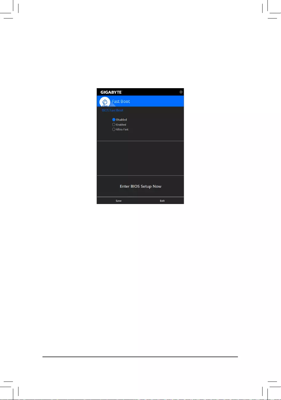
— 84 —
(Note) For more details about this function, refer to Chapter 2, «BIOS Setup.»
5-2-2 Fast Boot
Through the simple GIGABYTE Fast Boot interface, you can enable or change the Fast Boot or Next Boot
After AC Power Loss setting right in the operating system.
The Fast Boot Interface
Using Fast Boot
•BIOS Fast Boot:
This option is the same as the Fast Boot option (Note) in BIOS Setup. It allows you to enable or disable the
fast boot function to shorten OS boot time.
•Next Boot After AC Power Loss:
This option is the same as the Next Boot After AC Power Loss option (Note) in BIOS Setup. It allows you to
selectthesystembootupmodeuponthereturnofanACpowerloss.(Thismodeiscongurableonlywhen
BIOS Fast Boot is set to Enabled or Ultra Fast.)
Afteryoucongurethesettings,clickSave to save and click Exit. The settings will take effect on next boot. If
you click the Enter BIOS Setup Now button, the system will restart and enter BIOS Setup immediately.
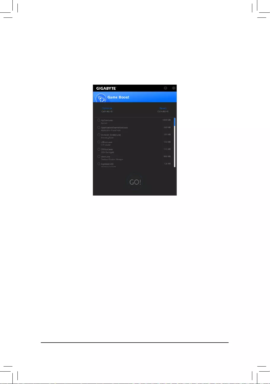
— 85 —
5-2-3 Game Boost
Thisappallowsyoutoexiblymanageyourapplicationstooptimizeyourgamingperformancebyfreeingup
system resources and memory usage.
The Game Boost Interface
Using Game Boost
Select the application you want to suspend and then click Gotooptimizeyoursystemforgaming.Torevert
the computer back to the state it was before, click Revert. In addition, two hotkeys are provided as follows:
•Optimize(Ctrl+Alt+B):Automaticallyoptimizesyourgamingplatformandgamingperformance.
•Revert(Ctrl+Alt+R):Restoresyourcomputerbacktothestatebeforethegamingbegins.
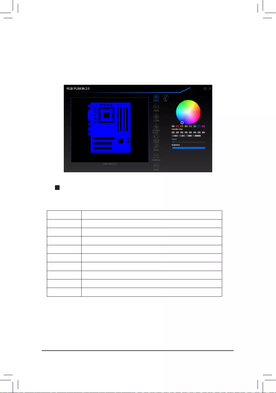
— 86 —
5-2-4 RGB Fusion
This application allows you to enable or specify the lighting mode of the select device (Note 1) while in the
Windows environment.
The RGB Fusion Interface
Using RGB Fusion
•The icon on the top right corner:AllowsyourcomputertoconnecttotheGIGABYTERGBFusionapp
installed on your handheld devices. (Note 2)
•ClicktheiconofthedesireddeviceandselecttheLEDcolor/lightingbehaviourontherightsectionofthescreen.
Static All LEDs emit a single color.
Pulse All LEDs simultaneously fade in and fade out.
Flash AllLEDssimultaneouslyashonandoff.
Double Flash AllLEDsashinaninterlacedpattern.
Color Cycle All LEDs simultaneously cycle through a full spectrum of colors.
Music AllLEDsaresynchronizedwithyourmusic.
Random SingleLEDregionsashrandomly.
Wave A full color spectrum cascades throughout the LED.
Game AllLEDsaresynchronizedwithyourgame.
Off Turn off all LEDs.
(Note1) RGBFusionwillautomaticallysearchforthedevicesthathaveLEDlightingfeatureanddisplaythem
on the list.
(Note 2) Please download the GIGABYTE RGB Fusion app from App Store or Google Play.
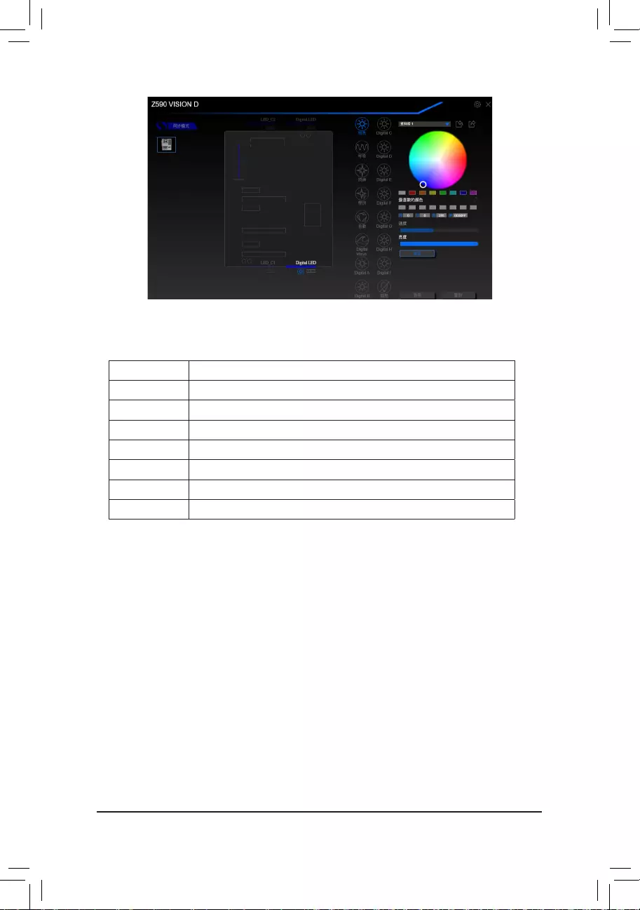
— 87 —
•Options for controlling the LEDs on the motherboard and digital LED strip. Click the motherboard icon for
further settings. (Note)
SelectyourdesiredareaandselecttheLEDcolor/lightingbehaviourontherightsectionofthescreen.
Static The selected region LEDs emit a single color.
Pulse The selected region LEDs simultaneously fade in and fade out.
Flash TheselectedregionLEDssimultaneouslyashonandoff.
Double Flash AllLEDsashinaninterlacedpattern.
Color Cycle All LEDs simultaneously cycle through a full spectrum of colors.
Digital Wave A full color spectrum cascades throughout the armor LED.
Digital A~I Mode Provides multiple digital lighting mode throughout the armor LED and LED strip.
Off Disable the selected region LEDs.
(Note) Regions/Modes/Colors available may vary by motherboard.
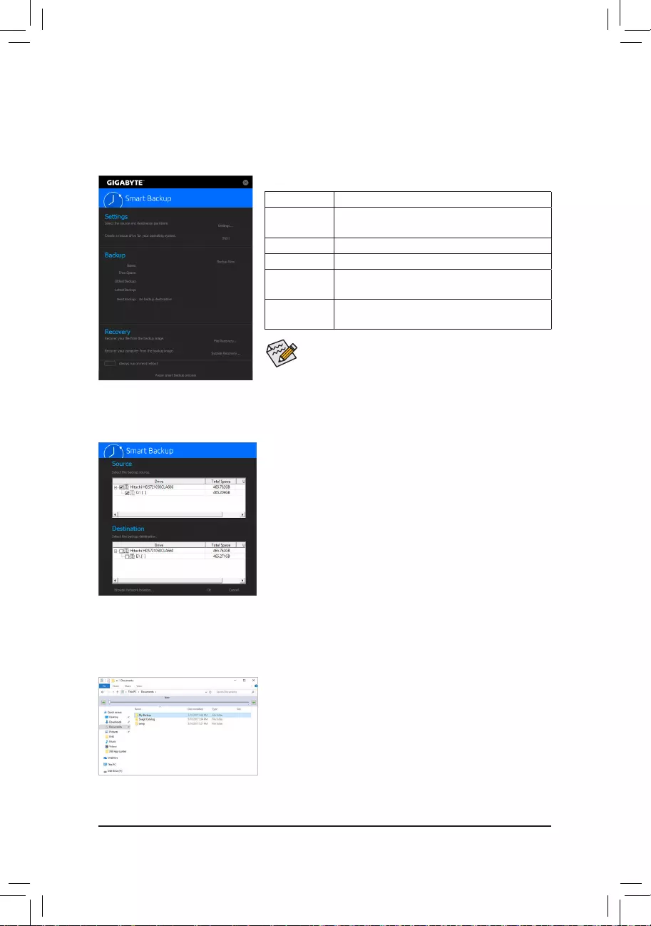
— 88 —
5-2-5 Smart Backup
SmartBackupallowsyoutobackupapartitionasanimageleeveryhour.Youcanusetheseimagestorestore
yoursystemorleswhenneeded.
•SmartBackuponlysupportsNTFSlesystem.
•You need to select the destination partition in Settingsthersttime
you use Smart Backup.
•The Backup Now button will be available only after 10 minutes you
have logged in Windows.
•Select the Always run on next reboot checkbox to automatically
enable Smart Backup after system reboot.
Creating a backup:
Click the Settings button on the main menu. In the Settings dialog
box, select the source partition and destination partition and click OK.
The initial backup will start after 10 minutes and regular backup will be
performed hourly. Note: By default, all partitions on the system drive
are selected as the backup source. The backup destination cannot be
on the same partition as the backup source.
Saving the backup to a network location:
If you want to save the backup to a network location, select Browse
network location. Make sure your computer and the computer where
you want to save the backup are in the same domain. Choose the
network location where you want to store the backup and enter the user
name and password. Follow the on-screen instructions to complete.
Recoveringale:
Click the File Recovery button on the main menu. Use the time slider on
the top of the popped out window to select a previous backup time. The
right pane will display the backed-up partitions in the backup destination
(in the My Backupfolder).Browsetotheleyouwantandcopyit.
The Smart Backup main menu:
Button Description
Settings Allows you to select the source and destination
partition
Start Allows you to create a rescue drive
Backup Now Allows you to perform the backup immediately
File
Recovery…
Allowsyoutorecoveryourlesfromthebackup
image
System
Recovery…
Allows you to recover your system from the
backup image
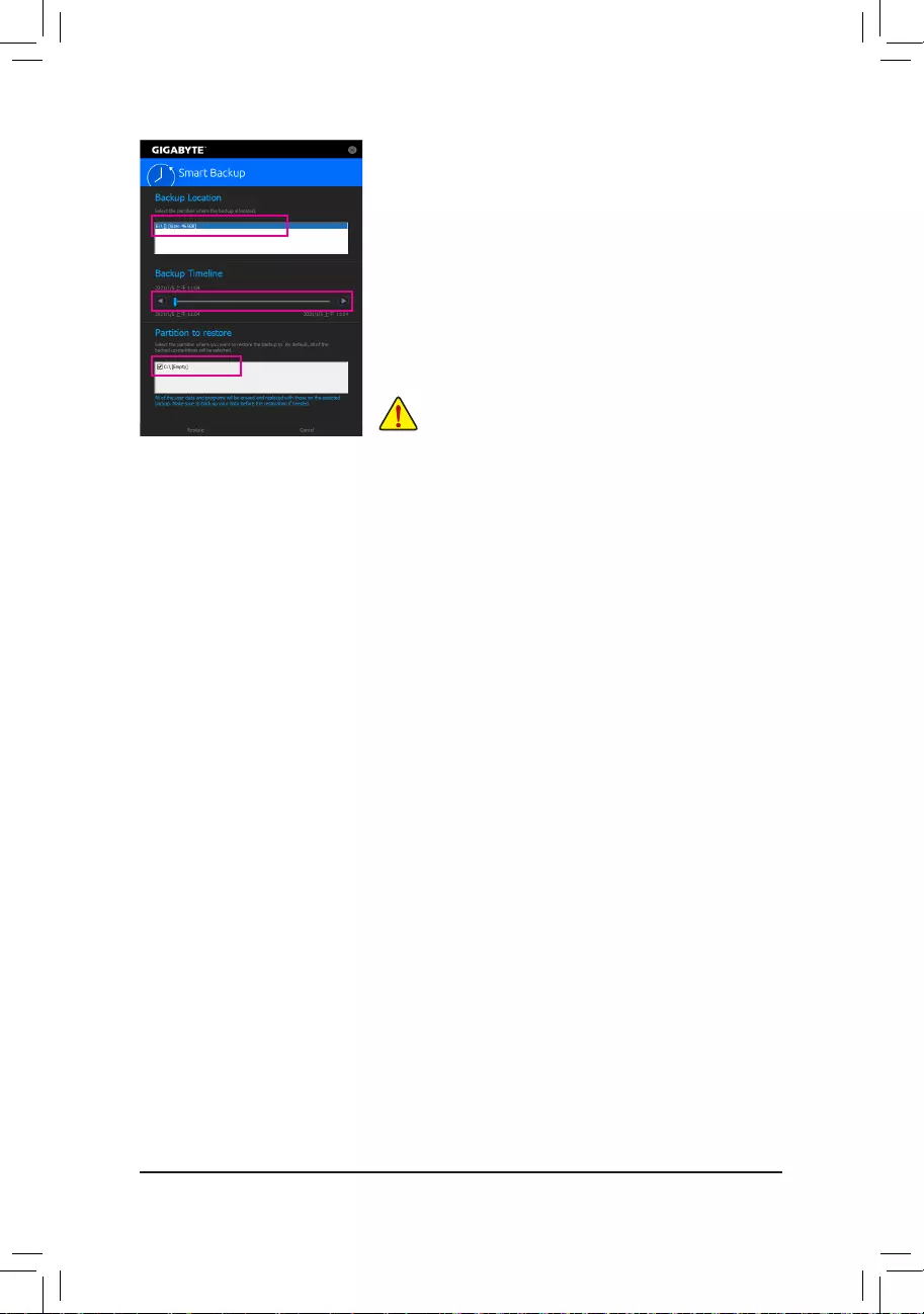
— 89 —
Recovering your system with Smart Backup:
Steps:
1. Click the System Recovery button on the main menu.
2. Select the location where your backup is saved.
3. Use the time slider to select a time point.
4. Select a partition backup created on the selected time point and
click Restore.
5. Conrmwhethertorestartyoursystemtoproceedwiththerestore
immediately or later. Once you respond «Yes» the system will restart to
the Windows recovery environment. Follow the onscreen instructions
to restore your system.
Allofyourlesandprogramswillbedeletedandreplacedwith
those on the selected backup. If needed, be sure to make a
copy of your data before the restore.
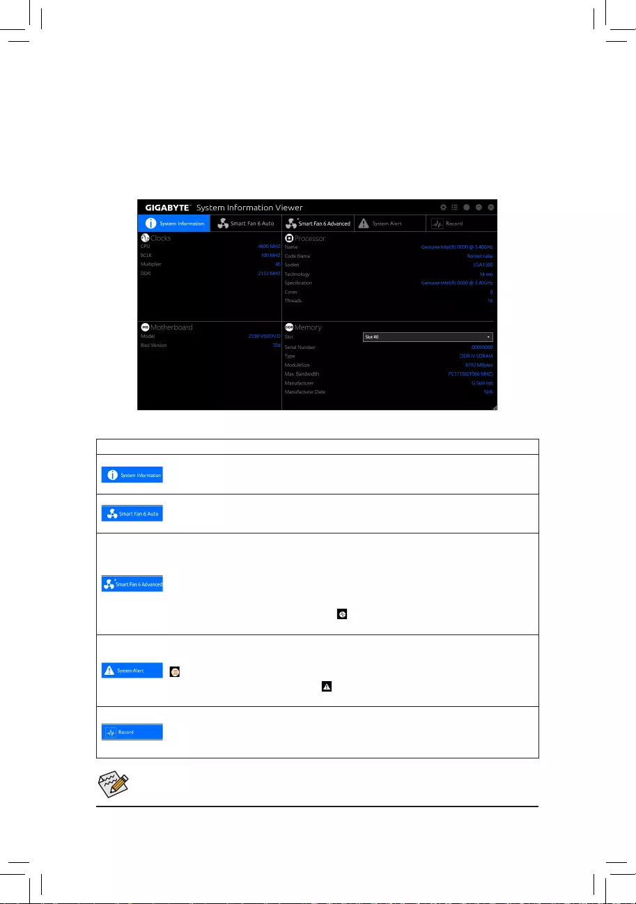
— 90 —
5-2-6 System Information Viewer
GIGABYTE System Information Viewer allows you to monitor and adjust the fan speed in the operating system.
You can also display the hardware monitor information on the desktop to view the system status at any time.
The System Information Viewer Interface
Tabs Information
Tab Description
The System Information tab provides information on the installed CPU, motherboard, and
the BIOS version.
The Smart Fan 6 Auto tab allows you to specify a Smart Fan mode.
The Smart Fan 6 Advanced tab allows you to adjust the smart fan speed. The fans will
run at different speeds according to system temperatures. Using the Smart Fan option you
can adjust the fan’s workload according system temperatures or you can x the fan speeds
using the RPM Fixed Mode option. Click the Calibrate button and the fan speed will be
shown in relation to overall fan workload after calibration. The Reset button can revert the
fan settings back to the last saved values. Noise Detection provides detection of the noise
level (measured in decibels) inside the chassis.
The System Alert tab allows you to monitor hardware temperature, voltage and fan speed,
and set temperature/fan speed alarm.
allows you to select what information to be displayed in quick mode (by default, all of the
hardware information are displayed); allows you to enable alert notication, click Apply
after selection.
The Record tab allows you to record changes in system voltages, temperatures, and fan
speeds. Please note, the recording will stop if you exit the Record tab during the recording
process.
•The speed control function requires the use of a fan with fan speed control design.
•To use the noise detection function, you must have a motherboard with a noise detection header.
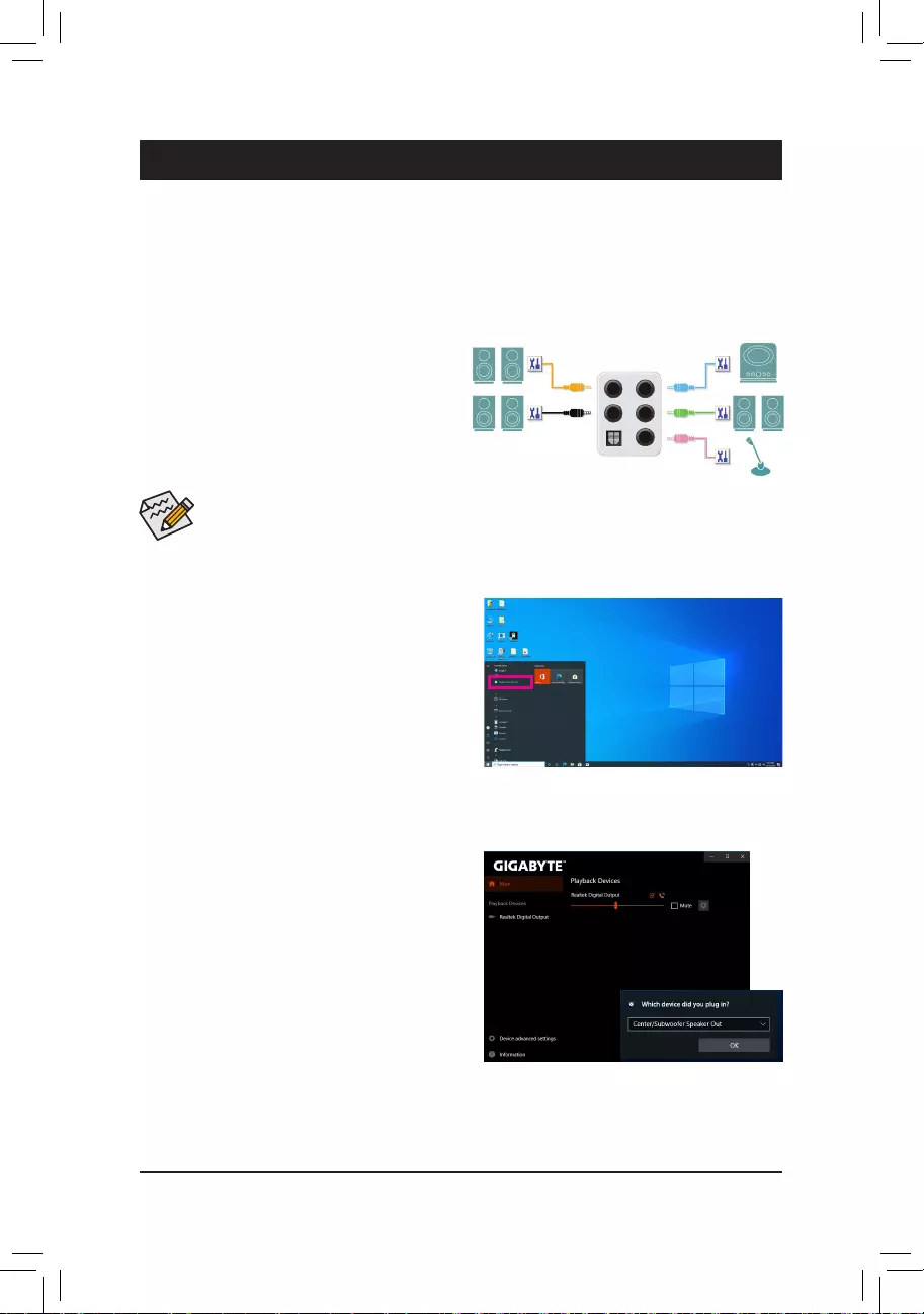
— 91 —
Chapter 6 Appendix
6-1 ConguringAudioInputandOutput
6-1-1 Conguring2/4/5.1/7.1-ChannelAudio
The motherboard provides five audio jacks on the
backpanelwhich support 2/4/5.1/7.1-channel audio.
The picture to the right shows the default audio jack
assignments.
After you install the included motherboard drivers, make sure your Internet connection works properly. The system
willautomaticallyinstalltheaudiodriverfromMicrosoftStore.Restartthesystemaftertheaudiodriverisinstalled.
A. Configuring Speakers
Step 1:
Go to the Start menu click the Realtek Audio Console.
For speaker connection, refer to the instructions
in Chapter 1, «Hardware Installation,» «Back Panel
Connectors.»
Toconfigure4/5.1/7.1-channel audio,youhave toretask the Linein jacktobe Sidespeakerout
through the audio driver.
Step 2:
Connect an audio device to an audio jack. The Which
device did you plut in ? dialog box appears. Select
the device according to the type of device you connect.
Then click OK.
Center/Subwoofer
Speaker Out Line In
RearSpeakerOut Front Speaker Out
Mic In
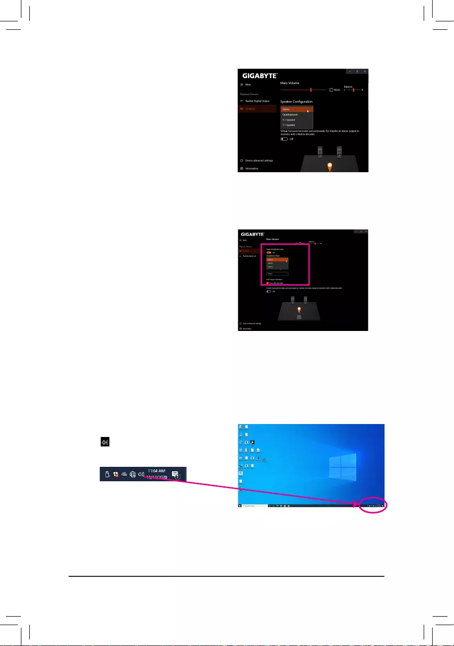
— 92 —
Step 3:
On the Speakers screen, click the Speaker Configuration
tab. In the Speaker Configuration list, select Stereo,
Quadraphonic, 5.1 Speaker, or 7.1 Speaker according
to the type of speaker configuration you wish to set up.
Then the speaker setup is completed.
B. Configuring Sound Effect
You may configure an audio environment on the Speakers tab.
C. Enabling Smart Headphone Amp
The Smart Headphone Amp feature automatically
detects impedance of your head-worn audio device,
whether earbuds or high-end headphones to provide
optimal audio dynamics. To enable this feature, connect
your head-worn audio device to the Line out jack on the
front panel and then go to the Speaker page. Enable
the Smart Headphone Amp feature. The Headphone
Power list below allows you to manually set the level of
headphone volume, preventing the volume from being
too high or too low.
Step 1:
Locate the icon in the notification area and right-click
on the icon. Select Open Sound settings.
* Configuring the Headphone
When you connect your headphone to the Line out jack on the back panel or front panel, make sure the default
playback device is configured correctly.
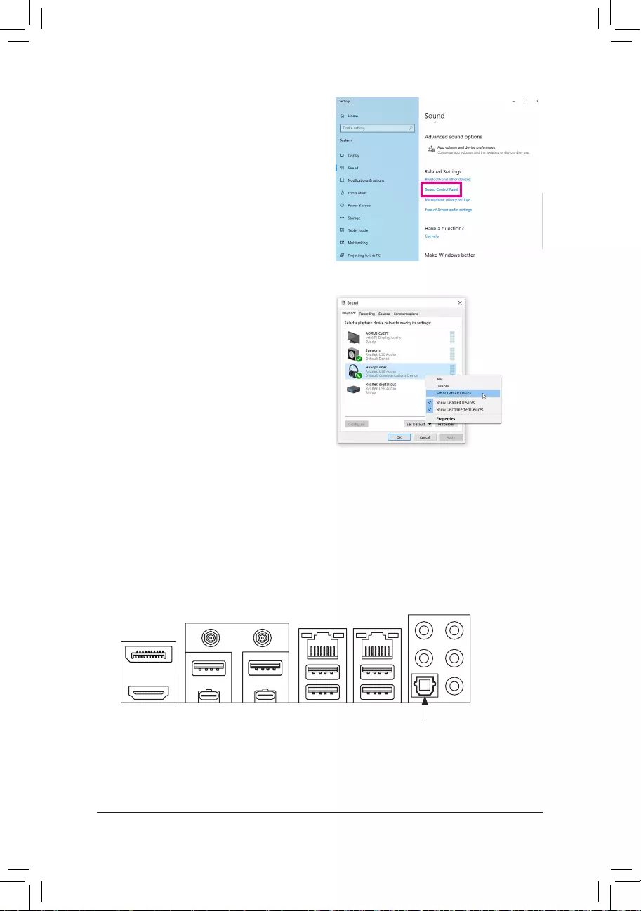
— 93 —
TheS/PDIFOutjackcantransmitaudiosignalstoanexternaldecoderfordecodingtogetthebestaudioquality.
1. Connecting a S/PDIF Out Cable:
ConnectaS/PDIFopticalcabletoanexternaldecoderfortransmittingtheS/PDIFdigitalaudiosignals.
6-1-2 ConguringS/PDIFOut
Step 2:
Select Sound Control Panel.
Step 3:
On the Playback tab, make sure your headphone is set
as the default playback device. For the device connected
to the Line out jack on the back panel, right-click on
Speakers and select Set as Default Device; for the
device connected to the Line out jack on the front panel,
right-click on Headphones.
ConnectstoaS/PDIFopticalcable
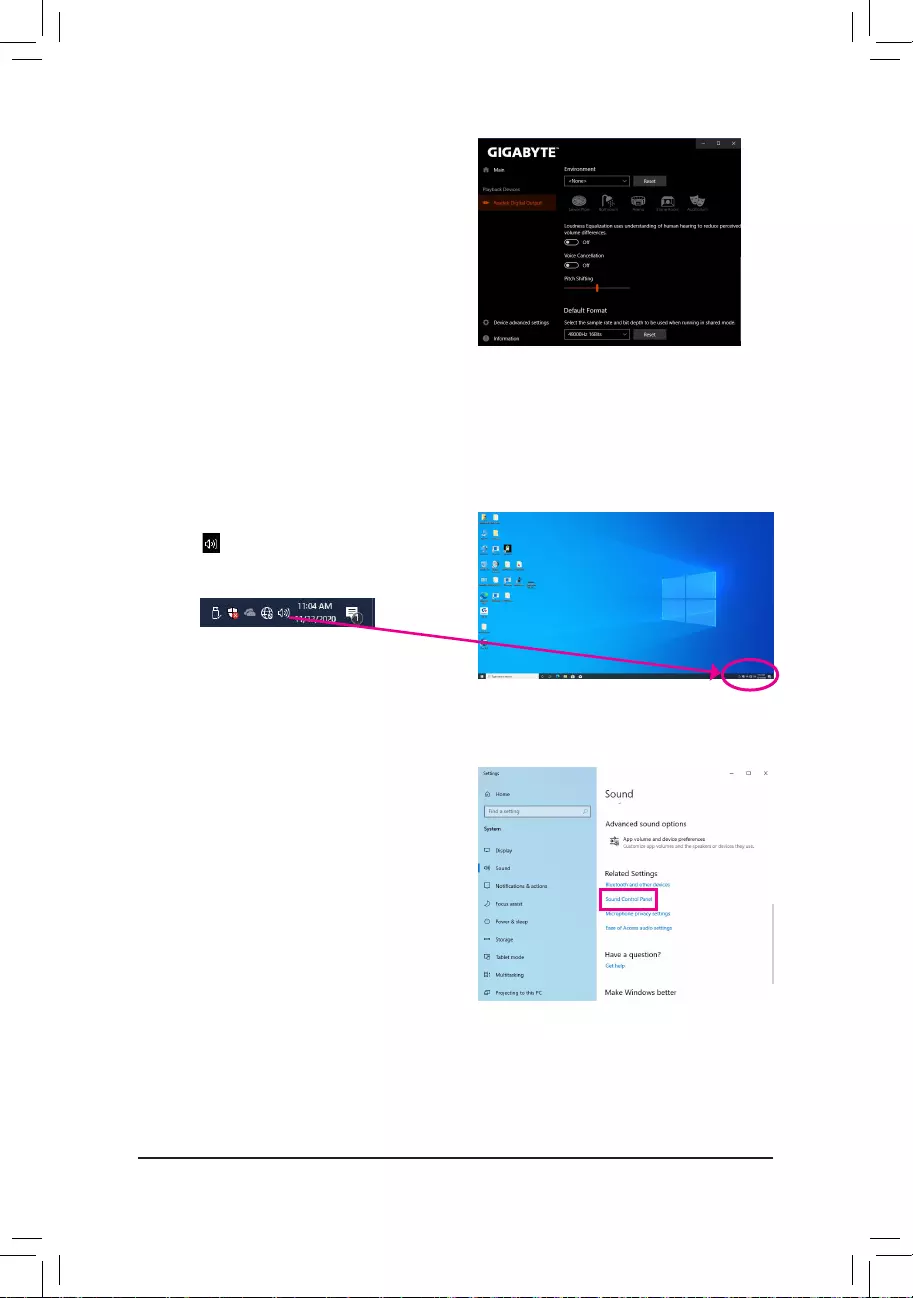
— 94 —
2. Configuring S/PDIF Out:
On the Realtek Digital Output screen, Select the sample
rate and bit depth in the Default Format section.
6-1-3 Stereo Mix
The following steps explain how to enable Stereo Mix (which may be needed when you want to record sound
from your computer).
Step 2:
Select Sound Control Panel.
Step 1:
Locate the icon in the notification area and right-click
on the icon. Select Open Sound settings.
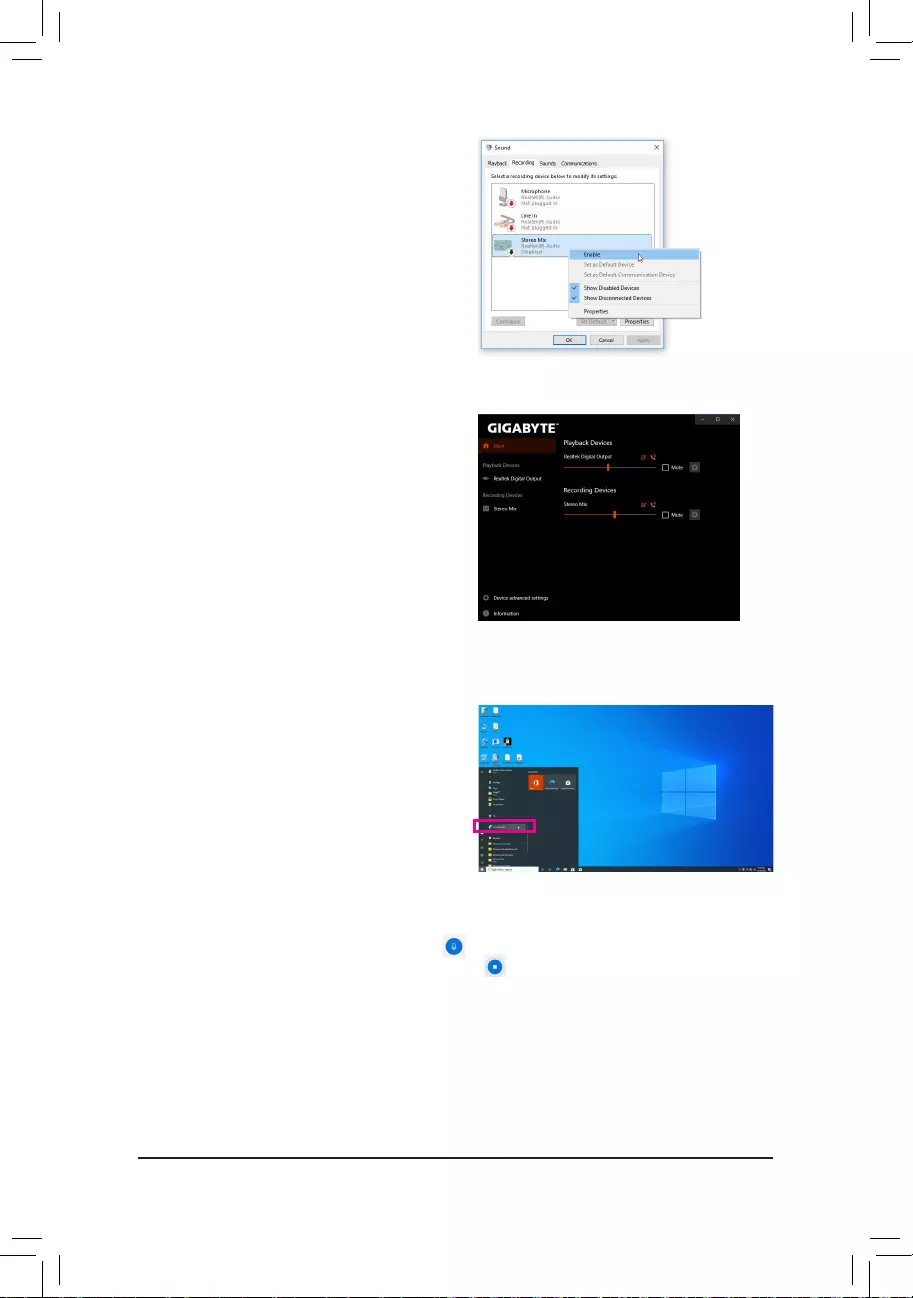
— 95 —
Step 4:
Now you can access the HD Audio Manager to configure
Stereo Mix and use Voice Recorder to record the sound.
Step 3:
On the Recording tab, right-click on Stereo Mix item and
select Enable. Then set it as the default device. (if you do
not see Stereo Mix, right-click on an empty space and
select Show Disabled Devices.)
6-1-4 Using the Voice Recorder
After setting up the audio input device, to open the
Voice Recorder, go to the Start menu and search for
Voice Recorder.
A. Recording Audio
1. To begin the recording, click the Record icon .
2. To stop the recording, click the Stop recording icon .
B. Playing the Recorded Sound
TherecordingswillsavedinDocuments>SoundRecordings.VoiceRecorderrecordsaudioinMPEG-4(.m4a)
format. You can play the recording with a digital media player program that supports the audio file format.
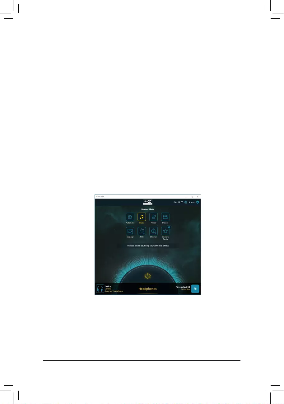
— 96 —
6-1-5 DTS:X® Ultra
Hear what you have been missing! DTS:X®Ultratechnologyisdesignedtoenhanceyourgaming,movies,AR,
andVRexperiencesonheadphonesandspeakers.Itdeliversanadvancedaudiosolutionthatrenderssounds
above, around, and close to you, stepping up your game play to new levels. Now with support for Microsoft
Spatial sound. Key features include:
•Believable 3D audio
DTS latest spatial audio rendering that delivers believable 3D audio over headphones and speakers.
•PC sound gets real
DTS:X decoding technology places sound where it would occur naturally in the real world.
•Hear sound as it was intended
Speaker and headphone tuning that preserves the audio experience as it was designed.
A. Using DTS:X Ultra
Step 1:
After you install the included motherboard drivers, make sure your Internet connection works properly. The
systemwillautomaticallyinstallDTS:XUltrafromtheMicrosoftStore.Restartthesystemafteritisinstalled.
Step 2:
Connect your audio device and select DTS:X Ultra on the Start menu. The Content Mode main menu allows
you to select content modes including Music, Video, and Movies, or you can select specifically tuned sound
modes,includingStrategy,RPG,andShooter,tosuitdifferentgamegenres.TheCustom Audio allows you to
createcustomizedaudioprofilesbasedonpersonalpreferenceforlateruse.
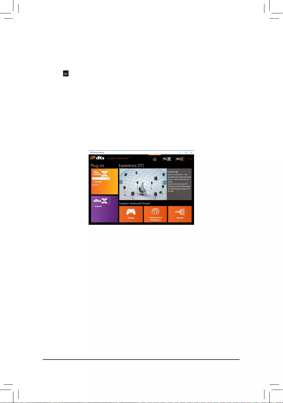
— 97 —
B. Using DTS Sound Unbound
Installing DTS Sound Unbound
Step 1:
Connect your headphones to the front panel line out jack and make sure your Internet connection works properly,
Locate the icon in the notification area and right-click on the icon. Click on Spatial Sound and then select
DTS Sound Unbound.
Step 2:
The system will connect to the Microsoft Store. When the DTS Sound Unbound application appears, click Install
and follow the on-screen instructions to proceed with the installation.
Step 3:
After the DTS Sound Unbound application is installed, click Launch. Accept the End User License Agreement
and restart the system.
Step 4:
Select DTS Sound Unbound on the Start menu. DTS Sound Unbound allows you to use the DTS Headphone:X
and DTS:X features.

— 98 —
6-2 Troubleshooting
6-2-1 Frequently Asked Questions
To read more FAQs for your motherboard, please go to the SupportFAQ page on GIGABYTE’s website.
Q: Whyisthelightofmykeyboard/opticalmousestillonafterthecomputershutsdown?
A: Some motherboards provide a small amount of standby power after the computer shuts down and that’s why the light is still
on.
Q: HowdoIcleartheCMOSvalues?
A: For motherboards that have a Clear CMOS button, press this button to clear the CMOS values (before doing this, please
turn off the computer and unplug the power cord). For motherboards that have a Clear CMOS jumper, refer to the instruc-
tionsinChapter1toshortthejumpertocleartheCMOSvalues.Ifyourboarddoesn’thavethisjumper/button,refertothe
instructions on the motherboard battery in Chapter 1. You can temporarily remove the battery from the battery holder to stop
supplying power to the CMOS, which will clear the CMOS values after about one minute.
Q: WhydoIstillgetaweaksoundeventhoughIhaveturnedmyspeakertothemaximumvolume?
A: Makesureyourspeakerisequippedwithaninternalamplier.Ifnot,tryaspeakerwithpower/amplier.
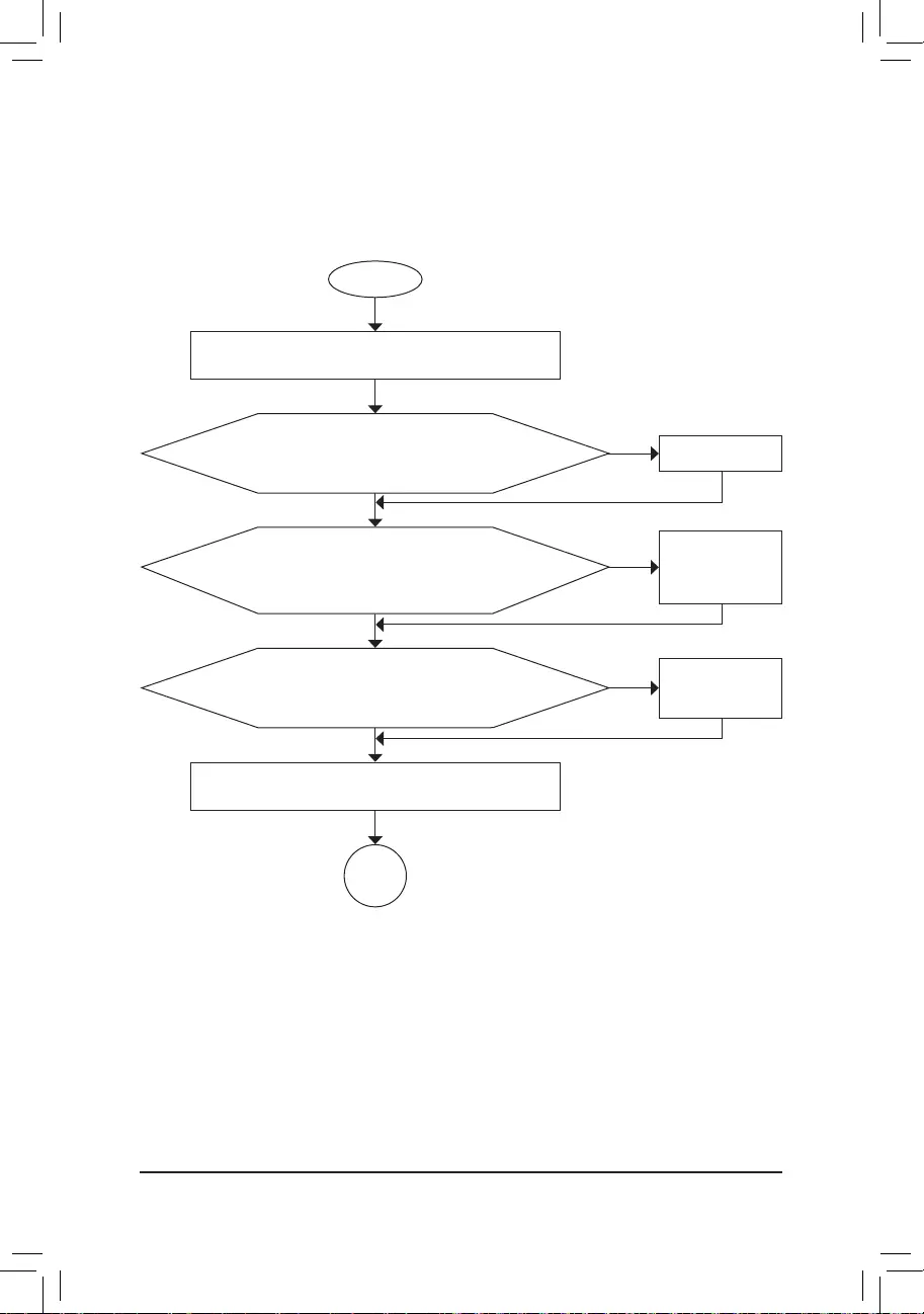
— 99 —
6-2-2 Troubleshooting Procedure
If you encounter any troubles during system startup, follow the troubleshooting procedure below to solve the
problem.
START
A
Turnoffthe power.Removeallperipherals,connecting cables, and
power cord etc.
Isolate the short circuit.
Secure the CPU cooler
on the CPU. Connect the
CPU cooler power cable
to the motherboard.
Correctly insert the
memory into the memory
socket.
(Continued…)
Yes
Theproblemisveriedandsolved.
Theproblemisveriedandsolved.
Theproblemisveriedandsolved.
No
No
No
Yes
Yes
Insert the graphics card. Connect the ATX main power cable and the
12V power cable. Turn on the power to start the computer.
Make sure the motherboard does not short-circuit with the chassis or
other metal objects.
Check if the CPU cooler is attached to the CPU securely. Is the
power connector of the CPU cooler connected to the CPU_FAN
headerproperly?
Check if the memory is installed properly on the memory slot.
Make sure the graphics card is securely seated in the
expansion slot and power connectors are firmly attached.
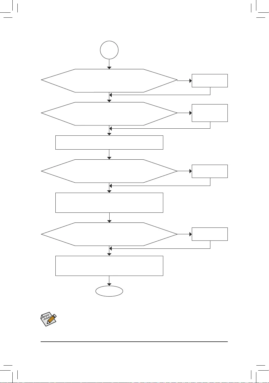
— 100 —
If the procedure above is unable to solve your problem, contact the place of purchase or local dealer
for help. Or go to the SupportTechnical Support page to submit your question. Our customer service
staff will reply you as soon as possible.
The power supply, CPU or
CPU socket might fail.
The keyboard or keyboard
connector might fail.
END
A
Turn off the computer. Plug in the keyboard and mouse and restart
the computer.
The graphics card,
expansion slot, or monitor
might fail.
The hard drive, connector,
or cable might fail.
No
Theproblemisveriedandsolved.
Theproblemisveriedandsolved.
Theproblemisveriedandsolved.
No
No
Yes
Yes
Yes
Reinstallthe operating system. Reinstall other devices oneby one
(install one device at one time and then boot the system to see if the
device works successfully).
Press<Delete>toenterBIOSSetup.Select«LoadOptimizedDefaults.»
Select «Save & Exit Setup» to save changes and exit BIOS Setup.
Check if there is display on your monitor.
Whenthecomputeristurnedon,istheCPUcoolerrunning?
Check if the keyboard is working properly.
No
Theproblemisveriedandsolved.
Yes
Turn off the computer and connect the hard drive(s). Check if the system
can boot successfully.

— 101 —
6-3 Debug LED Codes
Code Description
10 PEI Core is started.
11 Pre-memoryCPUinitializationisstarted.
12~14 Reserved.
15 Pre-memoryNorth-Bridgeinitializationisstarted.
16~18 Reserved.
19 Pre-memorySouth-Bridgeinitializationisstarted.
1A~2A Reserved.
2B~2F Memoryinitialization.
31 Memory installed.
32~36 CPUPEIinitialization.
37~3A IOHPEIinitialization.
3B~3E PCHPEIinitialization.
3F~4F Reserved.
60 DXE Core is started.
61 NVRAMinitialization.
62 Installation of the PCH runtime services.
63~67 CPUDXEinitializationisstarted.
68 PCIhostbridgeinitializationisstarted.
69 IOHDXEinitialization.
6A IOHSMMinitialization.
6B~6F Reserved.
70 PCHDXEinitialization.
71 PCHSMMinitialization.
72 PCHdevicesinitialization.
73~77 PCHDXEinitialization(PCHmodulespecific).
78 ACPICoreinitialization.
79 CSMinitializationisstarted.
7A~7F ReservedforAMIuse.
80~8F ReservedforOEMuse(OEMDXEinitializationcodes).
90 Phase transfer to BDS (Boot Device Selection) from DXE.
91 Issue event to connect drivers.
Regular Boot

— 102 —
Code Description
92 PCIBusinitializationisstarted.
93 PCIBushotpluginitialization.
94 PCI Bus enumeration for detecting how many resources are requested.
95 Check PCI device requested resources.
96 Assign PCI device resources.
97 Console Output devices connect (ex. Monitor is lighted).
98 Consoleinputdevicesconnect(ex.PS2/USBkeyboard/mouseareactivated).
99 SuperIOinitialization.
9A USBinitializationisstarted.
9B IssueresetduringUSBinitializationprocess.
9C Detect and install all currently connected USB devices.
9D Activated all currently connected USB devices.
9E~9F Reserved.
A0 IDEinitializationisstarted.
A1 IssueresetduringIDEinitializationprocess.
A2 Detect and install all currently connected IDE devices.
A3 Activated all currently connected IDE devices.
A4 SCSIinitializationisstarted.
A5 IssueresetduringSCSIinitializationprocess.
A6 Detect and install all currently connected SCSI devices.
A7 Activated all currently connected SCSI devices.
A8 Verify password if needed.
A9 BIOS Setup is started.
AA Reserved.
AB Wait user command in BIOS Setup.
AC Reserved.
AD IssueReadyToBooteventforOSBoot.
AE Boot to Legacy OS.
AF Exit Boot Services.
B0 RuntimeAPinstallationbegins.
B1 RuntimeAPinstallationends.
B2 LegacyOptionROMinitialization.
B3 System reset if needed.
— 103 —
Code Description
B4 USB device hot plug-in.
B5 PCI device hot plug.
B6 Clean-upofNVRAM.
B7 ReconfigureNVRAMsettings.
B8~BF Reserved.
C0~CF Reserved.
Code Description
E0 S3Resumeisstarted(calledfromDXEIPL).
E1 Fill boot script data for S3 resume.
E2 InitializesVGAforS3resume.
E3 OS S3 wake vector call.
S3 Resume
Code Description
F0 Recoverymodewillbetriggeredduetoinvalidfirmwarevolumedetection.
F1 Recoverymodewillbetriggeredbyuserdecision.
F2 Recoveryisstarted.
F3 Recoveryfirmwareimageisfound.
F4 Recoveryfirmwareimageisloaded.
F5~F7 ReservedforfutureAMIprogresscodes.
Recovery
Code Description
50~55 Memoryinitializationerroroccurs.
56 Invalid CPU type or speed.
57 CPU mismatch.
58 CPU self test failed or possible CPU cache error.
59 CPU micro-code is not found or micro-code update is failed.
5A Internal CPU error.
5B ResetPPIisfailed.
5C~5F Reserved.
D0 CPUinitializationerror.
D1 IOHinitializationerror.
Error

— 104 —
Code Description
D2 PCHinitializationerror.
D3 Some of the Architectural Protocols are not available.
D4 PCIresourceallocationerror.OutofResources.
D5 NoSpaceforLegacyOptionROMinitialization.
D6 No Console Output Devices are found.
D7 No Console Input Devices are found.
D8 It is an invalid password.
D9~DA Can’t load Boot Option.
DB Flash update is failed.
DC Resetprotocolisfailed.
DE~DF Reserved.
E8 S3 resume is failed.
E9 S3ResumePPIisnotfound.
EA S3ResumeBootScriptisinvalid.
EB S3 OS Wake call is failed.
EC~EF Reserved.
F8 RecoveryPPIisinvalid.
F9 Recoverycapsuleisnotfound.
FA Invalid recovery capsule.
FB~FF Reserved.

— 105 —
Supplier’s Declaration of Conformity
47 CFR § 2.1077 Compliance Information
Product Name: Motherboard
Trade Name: GIGABYTE
Model Number: Z590 VISION D
Responsible Party – U.S. Contact Information: G.B.T. Inc.
Address: 17358 Railroad street, City Of Industry, CA91748
Tel.: 1-626-854-9338
Internet contact information: https://www.gigabyte.com
FCC Compliance Statement:
This device complies with Part 15 of the FCC Rules, Subpart B, Unintentional Radiators.
Operation is subject to the following two conditions: (1) This device may not cause harmful interference, and (2) this
device must accept any interference received, including interference that may cause undesired operation.
Antenna use:
Inorderto comply with FCC RF exposure limits, low gain integrated
antennas should be located at a minimum distance of 7.9 inches (20 cm)
or more from the body of all persons.
Explosive Device Proximity Warning
Warning: Do not operate a portable transmitter (such as a wireless network
device) near unshielded blasting caps or in an explosive environment
unlessthedevicehasbeenmodiedtobequaliedforsuchuse.
Antenna Warning
The wireless adapter is not designed for use with high-gain antennas.
Use On Aircraft Caution
Caution:RegulationsoftheFCCandFAAprohibitairborneoperationof
radio-frequency wireless devices because their signals could interfere with
critical aircraft instruments.
Other Wireless Devices
SafetyNoticesforOtherDevicesintheWirelessNetwork:Refertothe
documentation supplied with wireless Ethernet adapters or other devices
in the wireless network.
Canada, Canada-Industry Notice:
Thisdevicecomplies with Industry Canada license-exempt RSS
standard(s). Operation is subject to the following two conditions:
(1) this device may not cause interference, and
(2) this device must accept any interference, including interference that
may cause undesired operation of the device.
Cetappareilest conforme aux normes Canada d’Industrie de RSS
permis-exempt. L’utilisation est assujetti aux deux conditions suivantes:
(1) le dispositif ne doit pas produire de brouillage préjudiciable, et
(2) ce dispositif doit accepter tout brouillage reçu, y compris un brouillage
susceptible de provoquer un fonctionnement indésirable.
Caution: When using IEEE 802.11a wireless LAN, this product is restricted
toindooruse due to its operation in the 5.15-to 5.25-GHz frequency
range. Industry Canada requires this product to be used indoors for the
frequencyrangeof5.15GHz to 5.25 GHz to reduce the potential for
harmful interference to co-channel mobile satellite systems. High power
radarisallocatedastheprimaryuserofthe5.25-to5.35-GHzand5.65to
5.85-GHzbands.Theseradarstationscancauseinterferencewithand/or
damage to this device. The maximum allowed antenna gain for use with
thisdeviceis6dBiinordertocomplywiththeE.I.R.Plimitforthe5.25-to
5.35and5.725to5.85GHzfrequencyrangeinpoint-to-pointoperation.To
complywithRFexposurerequirementsallantennasshouldbelocatedata
minimum distance of 20cm, or the minimum separation distance allowed
by the module approval, from the body of all persons.
Attention:l’utilisationd’unréseausanslIEEE802.11aestrestreinteà
uneutilisationenintérieuràcausedufonctionnementdanslabandede
fréquence5.15-5.25GHz.IndustryCanadarequiertqueceproduitsoit
utiliséàl’intérieurdesbâtimentspourlabandedefréquence5.15-5.25
GHzanderéduirelespossibilitésd’interférencesnuisiblesauxcanaux
co-existants des systèmes de transmission satellites. Les radars de
puissances ont fait l’objet d’une allocation primaire de fréquences dans
lesbandes5.25-5.35GHzet5.65-5.85GHz.Cesstationsradarpeuvent
créerdes interférences avecceproduit et/ou luiêtrenuisible. Le gain
d’antenne maximum permissible pour une utilisation avec ce produit est de
6dBiand’êtreconformeauxlimitesdepuissanceisotropiquerayonnée
équivalente(P.I.R.E.)applicable.
danslesbandes5.25-5.35GHzet5.725-5.85GHzenfonctionnement
point-à-point.Pourseconformerauxconditionsd’expositiondeRFtoutes
lesantennes devraient être localiséesà une distance minimumde 20
cm, ou la distance de séparation minimum permise par l’approbation du
module, du corps de toutes les personnes.
Regulatory Notices
United States of America, Federal Communications Commission Statement
TheFCCwithitsactioninETDocket96-8hasadoptedasafetystandardforhumanexposuretoradiofrequency(RF)electromagneticenergyemitted
byFCCcertiedequipment.TheIntelPRO/Wireless5000LANproductsmeettheHumanExposurelimitsfoundinOETBulletin65,2001,andANSI/
IEEE C95.1, 1992. Proper operation of this radio according to the instructions found in this manual will result in exposure substantially below the FCC’s
recommended limits.
The following safety precautions should be observed:
•Do not touch or move antenna while the unit is transmitting or receiving.
•Do not hold any component containing the radio such that the antenna is very close or touching any exposed parts of the body, especially the face
or eyes, while transmitting.
•Do not operate the radio or attempt to transmit data unless the antenna is connected; if not, the radio may be damaged.
•Useinspecicenvironments:
- Theuseofwirelessdevicesinhazardouslocationsislimitedbytheconstraintsposedbythesafetydirectorsofsuchenvironments.
— The use of wireless devices on airplanes is governed by the Federal Aviation Administration (FAA).
— The use of wireless devices in hospitals is restricted to the limits set forth by each hospital.

— 106 —
European Union (EU) CE Declaration of Conformity
This device complies with the following directives: Electromagnetic
CompatibilityDirective2014/30/EU, Low-voltageDirective2014/35/EU,
RadioEquipmentDirective2014/53/EU,ErPDirective2009/125/EC,RoHS
directive(recast)2011/65/EU&the2015/863Statement.
This product has been tested and found to comply with all essential
requirements of the Directives.
European Union (EU) RoHS (recast) Directive 2011/65/EU & the
European Commission Delegated Directive (EU) 2015/863 Statement
GIGABYTEproductshavenotintendedtoaddandsafefromhazardous
substances (Cd, Pb, Hg, Cr+6, PBDE, PBB, DEHP, BBP, DBP and DIBP).
ThepartsandcomponentshavebeencarefullyselectedtomeetRoHS
requirement. Moreover, we at GIGABYTE are continuing our efforts to
develop products that do not use internationally banned toxic chemicals.
European Union (EU) Community Waste Electrical & Electronic
Equipment (WEEE) Directive Statement
GIGABYTEwillfulllthenationallawsasinterpretedfromthe2012/19/
EU WEEE (Waste Electrical and Electronic Equipment) (recast) directive.
The WEEE Directive species the treatment, collection, recycling and
disposal of electric and electronic devices and their components. Under
the Directive, used equipment must be marked, collected separately, and
disposed of properly.
WEEE Symbol Statement
The symbol shown below is on the product or on its
packaging, which indicates that this product must not be
disposed of with other waste. Instead, the device should be
taken to the waste collection centers for activation of the
treatment, collection, recycling and disposal procedure.
For more information about where you can drop off your waste equipment
forrecycling,pleasecontactyourlocalgovernmentofce,yourhousehold
waste disposal service or where you purchased the product for details of
environmentally safe recycling.
End of Life Directives-Recycling
The symbol shown below is on the product or on its packaging,
which indicates that this product must not be disposed of with
other waste. Instead, the device should be taken to the waste
collection centers for activation of the treatment, collection,
recycling and disposal procedure.
Déclaration de Conformité aux Directives de l’Union européenne (UE)
Cet appareil portant la marque CE est conforme aux directives de l’UE
suivantes:directiveCompatibilitéElectromagnétique2014/30/UE,directive
BasseTension 2014/35/UE,directiveéquipements radioélectriques
2014/53/UE,ladirectiveRoHSII2011/65/UE&ladéclaration2015/863.
Laconformitéà ces directives est évaluée sur la base des normes
européennes harmonisées applicables.
European Union (EU) CE-Konformitätserklärung
DiesesProduktemitCE-KennzeichnungerfüllenfolgendenEU-Richtlinien:
EMV-Richtlinie 2014/30/EU, Niederspannungsrichtlinie2014/35/EU,
FunkanlagenRichtlinie2014/53/EU,RoHS-Richtlinie2011/65/EUerfüllt
unddie2015/863Erklärung.
DieKonformitätmit diesen Richtlinien wird unter Verwendungder
entsprechendenStandardszurEuropäischenNormierungbeurteilt.
CE declaração de conformidade
Este produto com a marcação CE estão em conformidade com das
seguintesDiretivasUE: Diretiva Baixa Tensão2014/35/EU; Diretiva
CEM2014/30/EU;DiretivaRSP2011/65/UEeadeclaração2015/863.
A conformidade com estas diretivas é vericada utilizando as normas
europeiasharmonizadas.
CE Declaración de conformidad
Este producto que llevan la marca CE cumplen con las siguientes
DirectivasdelaUniónEuropea:DirectivaEMC2014/30/EU,Directivade
bajovoltaje2014/35/EU,Directivadeequipamentosderádio2014/53/EU,
DirectivaRoHS2011/65/EUylaDeclaración2015/863.
El cumplimiento de estas directivas se evalúa mediante las normas
europeasarmonizadas.
CE Dichiarazione di conformità
I prodotti con il marchio CE sono conformi con una o più delle seguenti
DirettiveUE,comeapplicabile:DirettivaEMC2014/30/UE,Direttivasulla
bassatensione2014/35/UE,Direttivadiapparecchiatureradio2014/53/
UE,DirettivaRoHS2011/65/EUeDichiarazione2015/863.
La conformità con tali direttive viene valutata utilizzando gli Standard
europeiarmonizzatiapplicabili.
DeklaracjazgodnościUEUniiEuropejskiej
Urządzeniejestzgodnez następującymi dyrektywami: Dyrektywa
kompatybilnościelektromagnetycznej2014/30/UE,Dyrektywa
niskonapięciowej2014/35/UE,Dyrektywaurządzeńradiowych2014/53/
UE,DyrektywaRoHS2011/65/UEidyrektywa2015/863.
Niniejszeurządzeniezostałopoddanetestomistwierdzonojegozgodność
zwymaganiamidyrektywy.
ESProhlášeníoshodě
Toto zařízení splňuje požadavky Směrnice o Elektromagnetické
kompatibilitě 2014/30/EU, Směrnice o Nízkém napětí 2014/35/EU,
Směrniceorádiovýchzařízeních2014/53/EU,SměrniceRoHS2011/65/
EUa2015/863.
Tentoproduktbyltestovánabyloshledáno,žesplňujevšechnyzákladní
požadavkysměrnic.
EKmegfelelőséginyilatkozata
A termék megfelelnek az alábbi irányelvek és szabványok
követelményeinek, azok a kiállításidőpontjában érvényes, aktuális
változatában:EMCirányelv2014/30/EU, Kisfeszültségű villamos
berendezésekrevonatkozó irányelv 2014/35/EU, rádióberendezések
irányelv2014/53/EU,RoHSirányelv2011/65/EUés2015/863.
ΔήλωσησυμμόρφωσηςΕΕ
Είναισεσυμμόρφωσημετιςδιατάξεις των παρακάτω Οδηγιών
τηςΕυρωπαϊκήςΚοινότητας: Οδηγία 2014/30/ΕΕ σχετικά με την
ηλεκτρομαγνητικήσυμβατότητα, Οοδηγία χαμηλή τάση 2014/35/EU,
Οδηγία2014/53/ΕΕ σε ραδιοεξοπλισμό, Οδηγία RoHS 2011/65/ΕΕ
και2015/863.
Ησυμμόρφωσημεαυτέςτιςοδηγίεςαξιολογείταιχρησιμοποιώνταςτα
ισχύονταεναρμονισμέναευρωπαϊκάπρότυπα.
Under Industry Canada regulations, this radio transmitter may only operate
using an antenna of a type and maximum (or lesser) gain approved for
the transmitter by Industry Canada. To reduce potential radio interference
to other users, the antenna type and its gain should be chosen so that
the equivalent isotropically radiated power (e.i.r.p.) is not more than that
necessary for successful communication.
Conformémentàlaréglementationd’IndustrieCanada,leprésentémetteur
radio peut fonctionner avec une antenne d’un type et d’un gain maximal
(ou inférieur) approuvé pour l’émetteur par Industrie Canada. Dans le
butderéduirelesrisquesdebrouillageradioélectriqueàl’intentiondes
autres utilisateurs, il faut choisir le type d’antenne et son gain de sorte
que la puissance isotrope rayonnée équivalente (p.i.r.e.) ne dépasse pas
l’intensiténécessaireàl’établissementd’unecommunicationsatisfaisante.
— 107 —
European Community Radio Equipment Directive Compliance Statement:
ThisequipmentcomplieswithalltherequirementsandotherrelevantprovisionsofRadioEquipmentDirective2014/53/EU.
ThisequipmentissuitableforhomeandofceuseinalltheEuropeanCommunityMemberStatesandEFTAMemberStates.
Thelowband5.15-5.35GHzisforindooruseonly.
AT BE BG CH CY CZ DE
DK EE EL ES FI FR HR
HU IE IS IT LI LT LU
LV MT NL PL PT RO SE
SI SK TR UK
Wireless module manufacturer: Intel® Corporation SAS
Wireless module model name: AX200NGW
Taiwan NCC Wireless Statements / 無線設備警告聲明:
低功率電波輻射性電機管理辦法
第十二條: 經型式認證合格之低功率射頻電機,非經許可,公司、商號或使用者均不得擅自變更頻率、加大功率或變更原
設計之特性及功能。
第十四條: 低功率射頻電機之使用不得影響飛航安全及干擾合法通信;經發現有干擾現象時,應立即停用,並改善至無干
擾時方得繼續使用。前項合法通信,指依電信法規定作業之無線電通信。低功率射頻電機須忍受合法通信或工
業、科學及醫療用電波輻射性電機設備之干擾。
在5.25-5.35 秭赫頻帶內操作之無線資訊傳輸設備,限於室內使用。
Korea KCC NCC Wireless Statement:
5,25GHz-5,35GHz대역을 사용하는 무선 장치는 실내에서만 사용하도록 제한됩니다。
Japan Wireless Statement:
5.15GHz帯~5.35GHz帯: 屋内のみの使用。
Wireless module country approvals:
Wireless module manufacturer: Intel® Corporation
Wireless module model name: AX200NGW

— 108 —

— 109 —

— 110 —

— 111 —
Contact Us
•GIGA-BYTE TECHNOLOGY CO., LTD.
Address:No.6,BaoqiangRd.,XindianDist.,
New Taipei City 231, Taiwan
TEL: +886-2-8912-4000
FAX: +886-2-8912-4005
Tech.andNon-Tech.Support(Sales/Marketing):
https://esupport.gigabyte.com
WEBaddress(English):https://www.gigabyte.com
WEBaddress(Chinese):https://www.gigabyte.com/tw
•G.B.T. INC. — U.S.A.
TEL: +1-626-854-9338
FAX: +1-626-854-9326
Tech. Support: https://esupport.gigabyte.com
WarrantyInfo:http://rma.gigabyte.us
Webaddress:https://www.gigabyte.com/us
•G.B.T. INC (USA) — Mexico
Tel: +1-626-854-9338 x 215 (Soporte de habla hispano)
FAX: +1-626-854-9326
Correo: soporte@gigabyte-usa.com
Tech.Support:http://rma.gigabyte.us
Webaddress:https://www.gigabyte.com/latam
•Giga-Byte SINGAPORE PTE. LTD. — Singapore
WEBaddress:https://www.gigabyte.com/sg
•Thailand
WEBaddress:https://www.gigabyte.com/th
•Vietnam
WEBaddress:https://www.gigabyte.com/vn
•NINGBO G.B.T. TECH. TRADING CO., LTD. — China
WEBaddress:https://www.gigabyte.cn/
Shanghai
TEL: +86-21-63400912
FAX: +86-21-63400682
Beijing
TEL: +86-10-62102838
FAX: +86-10-62102848
Wuhan
TEL: +86-27-87685981
FAX: +86-27-87579461
GuangZhou
TEL: +86-20-87540700
FAX: +86-20-87544306
Chengdu
TEL: +86-28-85483135
FAX: +86-28-85256822
Xian
TEL: +86-29-85531943
FAX: +86-29-85510930
Shenyang
TEL: +86-24-83992342
FAX: +86-24-83992102
•GIGABYTE TECHNOLOGY (INDIA) LIMITED — India
WEBaddress:https://www.gigabyte.com/in
•Saudi Arabia
WEBaddress:https://www.gigabyte.com/sa
•Gigabyte Technology Pty. Ltd. — Australia
WEBaddress:https://www.gigabyte.com/au
— 112 —
•G.B.T. TECHNOLOGY TRADING GMBH — Germany
WEBaddress:https://www.gigabyte.com/de
•G.B.T. TECH. CO., LTD. — U.K.
WEBaddress:https://www.gigabyte.com/uk
•Giga-Byte Technology B.V. — The Netherlands
WEBaddress:https://www.gigabyte.com/nl
•GIGABYTE TECHNOLOGY FRANCE — France
WEBaddress:https://www.gigabyte.com/fr
•Sweden
WEBaddress:https://www.gigabyte.com/se
•Italy
WEBaddress:http://it.gigabyte.com/
•Spain
WEBaddress:http://es.gigabyte.com/
•Greece
WEBaddress:http://www.gigabyte.com.gr/
•Czech Republic
WEBaddress:http://www.gigabyte.cz/
•Hungary
WEBaddress:http://hu.gigabyte.com/
•Turkey
WEBaddress:http://www.gigabyte.com.tr/
•Russia
WEBaddress:http://www.gigabyte.ru/
•Poland
WEBaddress:http://www.gigabyte.pl/
•Ukraine
WEBaddress:http://www.gigabyte.ua/
•Romania
WEBaddress:https://www.gigabyte.com/ro
•Serbia
WEBaddress:http://www.gigabyte.rs/
•Kazakhstan
WEBaddress:http://www.gigabyte.kz/
•GIGABYTE eSupport
Tosubmitatechnicalornon-technical(Sales/Marketing)question,pleaselinkto:
https://esupport.gigabyte.com
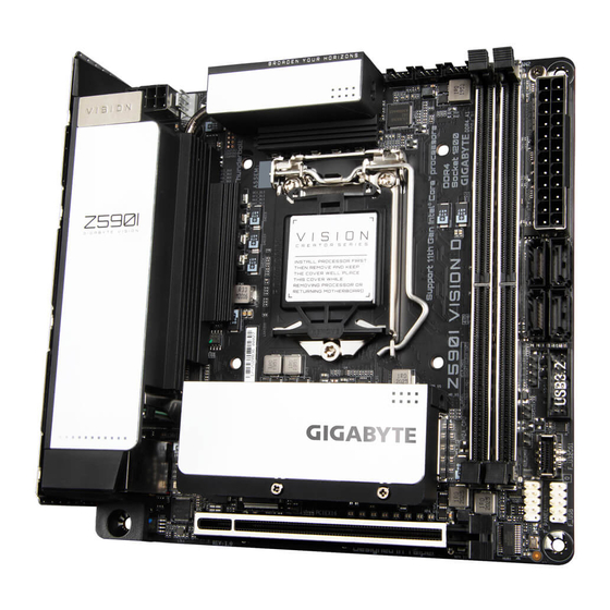
- Manuals
- Brands
- Gigabyte Manuals
- Motherboard
- Z590I VISION D
- User manual
-
Contents
-
Table of Contents
-
Bookmarks
Quick Links
Z590I VISION D
User’s Manual
Rev. 1001
12ME-Z59VSI-1001R
For more product details, please visit GIGABYTE’s website.
To reduce the impacts on global warming, the packaging materials of this product
are recyclable and reusable. GIGABYTE works with you to protect the environment.
Related Manuals for Gigabyte Z590I VISION D
Summary of Contents for Gigabyte Z590I VISION D
-
Page 1
Z590I VISION D User’s Manual Rev. 1001 12ME-Z59VSI-1001R For more product details, please visit GIGABYTE’s website. To reduce the impacts on global warming, the packaging materials of this product are recyclable and reusable. GIGABYTE works with you to protect the environment. -
Page 2
Information in this manual is protected by copyright laws and is the property of GIGABYTE. Changes to the specifications and features in this manual may be made by GIGABYTE without prior notice. No part of this manual may be reproduced, copied, translated, transmitted, or published in any form or by any means without GIGABYTE’s prior written permission. -
Page 3: Table Of Contents
Table of Contents Z590I VISION D Motherboard Layout …………….4 Z590I VISION D Motherboard Block Diagram …………..5 Chapter 1 Hardware Installation ………………6 Installation Precautions ………………6 Product Specifications ………………7 Installing the CPU ………………10 Installing the Memory ………………10 Installing an Expansion Card …………….. 11 Back Panel Connectors ………………
-
Page 4: Z590I Vision D Motherboard Layout
Z590I VISION D Motherboard Layout SYS_FAN2 ATX_12V_2X4 SYS_FAN3 CPU_FAN SYS_FAN1 LGA1200 TYPEC_1 Intel ® Thunderbolt ™ Controller TYPEC_2 QFLED E_AUDIO U32_G2_G1 M2_WIFI Intel Z590 ® (Note) (Note) D_LED U32_LAN ® Super I/O M_BIOS PCIEX16 Intel ® GbE LAN Temperature sensor…
-
Page 5: Z590I Vision D Motherboard Block Diagram
Z590I VISION D Motherboard Block Diagram PCI Express 4.0 /3.0 Bus (Note) CPU CLK+/- (100~500 MHz) DDR4 3200 /3000 /2933 (Note) (Note) (Note) 2666/2400/2133 MHz M.2 Socket 3 LGA1200 CPU (M2A_CPU) DisplayPort In Switch Intel 2 USB Type-C ® ®…
-
Page 6: Chapter 1 Hardware Installation
Chapter 1 Hardware Installation Installation Precautions The motherboard contains numerous delicate electronic circuits and components which can become damaged as a result of electrostatic discharge (ESD). Prior to installation, carefully read the user’s manual and follow these procedures: • Prior to installation, make sure the chassis is suitable for the motherboard. •…
-
Page 7: 1-2 Product Specifications
Support for non-ECC Un-buffered DIMM 1Rx8/2Rx8/1Rx16 memory modules Š Support for Extreme Memory Profile (XMP) memory modules Š (Go to GIGABYTE’s website for the latest supported memory speeds and memory modules.) Onboard Integrated Graphics Processor+Intel Thunderbolt 4 Controller: ®…
-
Page 8
1 x PCI Express x16 slot, running at x16 Š Expansion Slots (The PCI Express x16 slot conforms to PCI Express 4.0 standard.) (Note) Storage Interface Š CPU: 1 x M.2 connector (Socket 3, M key, type 2260/2280 PCIe 4.0 x4/x2 SSD support) (M2A_CPU) (Note) Chipset:… -
Page 9
System Form Factor Mini-ITX Form Factor; 17.0cm x 17.0cm Š * GIGABYTE reserves the right to make any changes to the product specifications and product-related information without prior notice. Please visit the SupportUtility List Please visit GIGABYTE’s website for support lists of CPU, memory page on GIGABYTE’s website to modules, SSDs, and M.2 devices. -
Page 10: Installing The Cpu
• Make sure that the motherboard supports the memory. It is recommended that memory of the same capacity, brand, speed, and chips be used. (Go to GIGABYTE’s website for the latest supported memory speeds and memory modules.) • Always turn off the computer and unplug the power cord from the power outlet before installing the memory to prevent hardware damage.
-
Page 11: Installing An Expansion Card
Due to CPU limitations, read the following guidelines before installing the memory in Dual Channel mode. Dual Channel mode cannot be enabled if only one memory module is installed. When enabling Dual Channel mode with two memory modules, it is recommended that memory of the same capacity, brand, speed, and chips be used.
-
Page 12
(actual effects may vary by the device being used). Mic In The Mic in jack. (Note) To enable the Q-Flash Plus function please visit the «Unique Features» webpage of GIGABYTE’s website. Please visit GIGABYTE’s website for details on configuring the audio software. — 12 -… -
Page 13: Internal Connectors
Internal Connectors ATX_12V_2X4 F_PANEL SPEAKER CPU_FAN F_U32G1 SYS_FAN1/2/3 F_U32CG1 D_LED F_USB LED_C SATA3 0/2/3/4 CLR_CMOS M2A_CPU/M2P_SB (Note) (Note) The M2P_SB connector is on the back of the motherboard. Read the following guidelines before connecting external devices: • First make sure your devices are compliant with the connectors you wish to connect. •…
-
Page 14
1/2) ATX_12V_2X4/ATX (2×4 12V Power Connector and 2×12 Main Power Connector) With the use of the power connector, the power supply can supply enough stable power to all the components on the motherboard. Before connecting the power connector, first make sure the power supply is turned off and all devices are properly installed. -
Page 15
LED strip. For how to turn on/off the lights of the LED strip please visit the «Unique Features» webpage of GIGABYTE’s website. Before installing the devices, be sure to turn off the devices and your computer. Unplug the power cord from the power outlet to prevent damage to the devices. -
Page 16
DEBUG PORT 7) SATA3 0/2/3/4 (SATA 6Gb/s Connectors) The SATA connectors conform to SATA 6Gb/s standard and are compatible with SATA 3Gb/s and SATA 1.5Gb/s standard. Each SATA connector supports a single SATA device. The Intel Chipset supports RAID 0, ®… -
Page 17
9) F_PANEL (Front Panel Header) Connect the power switch, reset switch, and system status indicator on the chassis to this header according to the pin assignments below. Note the positive and negative pins before connecting the cables. Hard Drive PLED+ Activity LED Power LED PLED-… -
Page 18
F_USB30 F_ U 11) F_U32G1 (USB 3.2 Gen 1 Header) The header conforms to USB 3.2 Gen 1 and USB 2.0 specification and can provide two USB ports. For purchasing the optional 3.5″ front panel that provides two USB 3.2 Gen 1 ports, please contact the local dealer. -
Page 19
B S S B S_ 14) CI (Chassis Intrusion Header) This motherboard provides a chassis detection feature that detects if the chassis cover has been removed. This function requires a chassis with chassis intrusion detection design. Pin No. Definition S B_ 1 2 3 Signal 15) CLR_CMOS (Clear CMOS Jumper) -
Page 20: Chapter 2 Bios Setup
To access the BIOS Setup program, press the <Delete> key during the POST when the power is turned on. To upgrade the BIOS, use either the GIGABYTE Q-Flash or @BIOS utility. Q-Flash allows the user to quickly and easily upgrade or back up BIOS without entering the operating system.
-
Page 21: The Main Menu
The Main Menu System Time Setup Menus Configuration Hardware Items Information Configuration Items Current Settings Quick Access Bar allows you to quickly move to the General Help, Easy Mode, Smart Fan 6, or Q-Flash screen. Advanced Mode Function Keys <f><g> Move the selection bar to select a setup menu <h><i>…
-
Page 22: Smart Fan 6
Smart Fan 6 Use the <F6> function key to quickly switch to this screen. This screen allows you to configure fan speed related settings for each fan header or monitor your system/CPU temperature. & TUNE ALL Allows you to apply the current settings to all fan headers. &…
-
Page 23
& FAN Mode Allows you to set the operating mode for the fan. Adjusts the fan speed linearly based on the temperature. (Default) Slope Adjusts the fan speed stepwise based on the temperature. Stair & FAN Fail Warning Allows the system to emit warning sound if the fan is not connected or fails. Check the fan condition or fan connection when this occurs. -
Page 24: Favorites (F11)
Favorites (F11) Set your frequently used options as your favorites and use the <F11> key to quickly switch to the page where all of your favorite options are located. To add or remove a favorite option, go to its original page and press <Insert>…
-
Page 25: Tweaker
Tweaker Whether the system will work stably with the overclock/overvoltage settings you made is dependent on your overall system configurations. Incorrectly doing overclock/overvoltage may result in damage to CPU, chipset, or memory and reduce the useful life of these components. This page is for advanced users only and we recommend you not to alter the default settings to prevent system instability or other unexpected results.
-
Page 26
& AVX Offset (Note) When the processor runs AVX workloads, the CPU Clock Ratio will be reduced by the desired AVX offset value. For example, if the value is set to 3, the CPU Clock Ratio will be reduced by 3 when executing AVX instructions. -
Page 27
& Race To Halt (RTH) /Energy Efficient Turbo (Note) (Note) Enables or disables the CPU power saving related settings. (Default: Auto) & Intel(R) Turbo Boost Technology (Note) Allows you to determine whether to enable the Intel CPU Turbo Boost technology. Auto lets the BIOS ®… -
Page 28
& C6/C7 State Support Allows you to determine whether to let the CPU enter C6/C7 mode in system halt state. When enabled, the CPU core frequency and voltage will be reduced during system halt state to decrease power consumption. The C6/C7 state is a more enhanced power-saving state than C3. Auto lets the BIOS automatically configure this setting. -
Page 29
& Memory Ref Clock Allows you to manually adjust the memory reference clock. (Default: Auto) & Memory Odd Ratio (100/133 or 200/266) (Note) Enabled allows Qclk to run in odd frequency. (Default: Auto) & Gear Mode (Note) Allows you to improve the maximum OC frequency potential. (Default: Auto) ƒ… -
Page 30
& Vcore Volatge Mode/CPU Vcore/Dynamic Vcore(DVID)/BCLK Adaptive Voltage/CPU Graphics Voltage (VAXG)/DRAM Voltage (CH A/B)/CPU VCCIO/CPU System Agent Voltage/ VCC Substained/VCCPLL/VCCPLL OC/VCCVTT/ VCC STG/ VCC18 PCH/VCC1V8P These items allow you to adjust the CPU Vcore and memory voltages. ƒ Advanced Voltage Settings This submenu allows you to configure Load-Line Calibration level, over-voltage protection level, and over- current protection level. -
Page 31: Settings
Settings ƒ Platform Power & Platform Power Management Enables or disables the Active State Power Management function (ASPM). (Default: Disabled) & PEG ASPM Allows you to configure the ASPM mode for the device connected to the CPU PEG bus. This item is configurable only when Platform Power Management is set to Enabled.
-
Page 32
& RC6(Render Standby) Allows you to determine whether to let the onboard graphics enter standby mode to decrease power consumption. (Default: Enabled) & AC BACK Determines the state of the system after the return of power from an AC power loss. The system returns to its last known awake state upon the return of the AC power. -
Page 33
ƒ USB Configuration & Legacy USB Support Allows USB keyboard/mouse to be used in MS-DOS. (Default: Enabled) & XHCI Hand-off Determines whether to enable XHCI Hand-off feature for an operating system without XHCI Hand-off support. (Default: Enabled) & USB Mass Storage Driver Support Enables or disables support for USB storage devices. -
Page 34
& Aggressive LPM Support Enables or disables the power saving feature, ALPM (Aggressive Link Power Management), for the Chipset SATA controllers. (Default: Disabled) & Port 0/2/3/4 Enables or disables each SATA port. (Default: Enabled) & SATA Port 0/2/3/4 DevSlp Allows you to determine whether to let the connected SATA device go into sleep mode. (Default: Disabled) &… -
Page 35
ƒ PC Health Status & Reset Case Open Status Keeps or clears the record of previous chassis intrusion status. (Default) Disabled Clears the record of previous chassis intrusion status and the Case Open field will Enabled show «No» at next boot. &… -
Page 36: System Info
System Info. This section provides information on your motherboard model and BIOS version. You can also select the default language used by the BIOS and manually set the system time. & Access Level Displays the current access level depending on the type of password protection used. (If no password is set, the default will display as Administrator.) The Administrator level allows you to make changes to all BIOS settings;…
-
Page 37: Boot
System (Default) & Full Screen LOGO Show Allows you to determine whether to display the GIGABYTE Logo at system startup. Disabled skips the GIGABYTE Logo when the system starts up. (Default: Enabled) & Boot Option Priorities Specifies the overall boot order from the available devices. Removable storage devices that support GPT format will be prefixed with «UEFI:»…
-
Page 38
& VGA Support Allows you to select which type of operating system to boot. Enables legacy option ROM only. Auto EFI Driver Enables EFI option ROM. (Default) This item is configurable only when Fast Boot is set to Enabled or Ultra Fast. &… -
Page 39
& Administrator Password Allows you to configure an administrator password. Press <Enter> on this item, type the password, and then press <Enter>. You will be requested to confirm the password. Type the password again and press <Enter>. You must enter the administrator password (or user password) at system startup and when entering BIOS Setup. -
Page 40: Save & Exit
Save & Exit & Save & Exit Setup Press <Enter> on this item and select Yes. This saves the changes to the CMOS and exits the BIOS Setup program. Select No or press <Esc> to return to the BIOS Setup Main Menu. &…
-
Page 41: Chapter 3 Appendix
Chapter 3 Appendix 3-1 Configuring a RAID Set RAID Levels RAID 0 RAID 1 RAID 5 RAID 10 Minimum Number ≥2 ≥3 of Hard Drives Number of hard Size of the smallest (Number of hard (Number of hard Array Capacity drives * Size of the drive drives -1) * Size of drives/2) * Size of the…
-
Page 42: Installing Intel ® Optane ™ Memory And Storage Management
Windows 10 64-bit (or later version) installed on it. The data drive must also be GPT formatted. 6. The motherboard driver disc. 7. The SATA controller must set in Intel RST Premium With Intel Optane System Acceleration mode. Please visit GIGABYTE’s website for details on configuring a RAID array. — 42 -…
-
Page 43
A-2. Installation Guidelines 1. Go to SettingsIO PortsSATA And RST Configuration and make sure RST Control PCIe Storage Devices is set to Manual. Then depending on which M.2 connector you install the Optane memory in, set ™ the corresponding PCIe Storage Dev on Port XX item to RST Controlled. 2. -
Page 44: Drivers Installation
You can click the Xpress Install button and «Xpress Install» will install all of the selected drivers. Or click the arrow icon to individually install the drivers you need. Please visit GIGABYTE’s website for Please visit GIGABYTE’s website for more software information.
-
Page 45: Regulatory Notices
Supplier’s Declaration of Conformity 47 CFR § 2.1077 Compliance Information Product Name: Motherboard Trade Name: GIGABYTE Model Number: Z590I VISION D Responsible Party – U.S. Contact Information: G.B.T. Inc. Address: 17358 Railroad street, City Of Industry, CA91748 Tel.: 1-626-854-9338 Internet contact information: https://www.gigabyte.com FCC Compliance Statement: This device complies with Part 15 of the FCC Rules, Subpart B, Unintentional Radiators.
-
Page 46
European Commission Delegated Directive (EU) 2015/863 Statement I prodotti con il marchio CE sono conformi con una o più delle seguenti GIGABYTE products have not intended to add and safe from hazardous Direttive UE, come applicabile: Direttiva EMC 2014/30/UE, Direttiva sulla substances (Cd, Pb, Hg, Cr+6, PBDE, PBB, DEHP, BBP, DBP and DIBP). -
Page 47
European Community Radio Equipment Directive Compliance Statement: This equipment complies with all the requirements and other relevant provisions of Radio Equipment Directive 2014/53/EU. This equipment is suitable for home and office use in all the European Community Member States and EFTA Member States. The low band 5.15 -5.35 GHz is for indoor use only. -
Page 48: Contact Us
Contact Us GIGA-BYTE TECHNOLOGY CO., LTD. Address: No.6, Baoqiang Rd., Xindian Dist., New Taipei City 231, Taiwan TEL: +886-2-8912-4000, FAX: +886-2-8912-4005 Tech. and Non-Tech. Support (Sales/Marketing) : https://esupport.gigabyte.com WEB address (English): https://www.gigabyte.com WEB address (Chinese): https://www.gigabyte.com/tw GIGABYTE eSupport • To submit a technical or non-technical (Sales/Marketing) question, please link to: https://esupport.gigabyte.com…
Посмотреть инструкция для Gigabyte Z590 Vision D бесплатно. Руководство относится к категории материнские платы, 3 человек(а) дали ему среднюю оценку 7.9. Руководство доступно на следующих языках: английский. У вас есть вопрос о Gigabyte Z590 Vision D или вам нужна помощь? Задайте свой вопрос здесь
Не можете найти ответ на свой вопрос в руководстве? Вы можете найти ответ на свой вопрос ниже, в разделе часто задаваемых вопросов о Gigabyte Z590 Vision D.
Какая ширина Gigabyte Z590 Vision D?
Gigabyte Z590 Vision D имеет ширину 305 mm.
Какая толщина Gigabyte Z590 Vision D?
Gigabyte Z590 Vision D имеет толщину 244 mm.
Какой тип USB-подключения Gigabyte Z590 Vision D имеет?
Gigabyte Z590 Vision D имеет USB Type-A, USB Type-C подключение.
Инструкция Gigabyte Z590 Vision D доступно в русский?
К сожалению, у нас нет руководства для Gigabyte Z590 Vision D, доступного в русский. Это руководство доступно в английский.
Не нашли свой вопрос? Задайте свой вопрос здесь